EP4043644A1 - Bedienerkabine mit schutzgitter - Google Patents
Bedienerkabine mit schutzgitter Download PDFInfo
- Publication number
- EP4043644A1 EP4043644A1 EP22155564.2A EP22155564A EP4043644A1 EP 4043644 A1 EP4043644 A1 EP 4043644A1 EP 22155564 A EP22155564 A EP 22155564A EP 4043644 A1 EP4043644 A1 EP 4043644A1
- Authority
- EP
- European Patent Office
- Prior art keywords
- operator
- cab
- grille
- roof
- protective position
- Prior art date
- Legal status (The legal status is an assumption and is not a legal conclusion. Google has not performed a legal analysis and makes no representation as to the accuracy of the status listed.)
- Withdrawn
Links
Images


Classifications
-
- E—FIXED CONSTRUCTIONS
- E02—HYDRAULIC ENGINEERING; FOUNDATIONS; SOIL SHIFTING
- E02F—DREDGING; SOIL-SHIFTING
- E02F9/00—Component parts of dredgers or soil-shifting machines, not restricted to one of the kinds covered by groups E02F3/00 - E02F7/00
- E02F9/16—Cabins, platforms, or the like, for drivers
- E02F9/163—Structures to protect drivers, e.g. cabins, doors for cabins; Falling object protection structure [FOPS]; Roll over protection structure [ROPS]
-
- B—PERFORMING OPERATIONS; TRANSPORTING
- B62—LAND VEHICLES FOR TRAVELLING OTHERWISE THAN ON RAILS
- B62D—MOTOR VEHICLES; TRAILERS
- B62D33/00—Superstructures for load-carrying vehicles
- B62D33/06—Drivers' cabs
-
- B—PERFORMING OPERATIONS; TRANSPORTING
- B60—VEHICLES IN GENERAL
- B60R—VEHICLES, VEHICLE FITTINGS, OR VEHICLE PARTS, NOT OTHERWISE PROVIDED FOR
- B60R19/00—Wheel guards; Radiator guards, e.g. grilles; Obstruction removers; Fittings damping bouncing force in collisions
- B60R19/02—Bumpers, i.e. impact receiving or absorbing members for protecting vehicles or fending off blows from other vehicles or objects
- B60R19/24—Arrangements for mounting bumpers on vehicles
- B60R19/38—Arrangements for mounting bumpers on vehicles adjustably or movably mounted, e.g. horizontally displaceable for securing a space between parked vehicles
-
- B—PERFORMING OPERATIONS; TRANSPORTING
- B60—VEHICLES IN GENERAL
- B60R—VEHICLES, VEHICLE FITTINGS, OR VEHICLE PARTS, NOT OTHERWISE PROVIDED FOR
- B60R21/00—Arrangements or fittings on vehicles for protecting or preventing injuries to occupants or pedestrians in case of accidents or other traffic risks
- B60R21/02—Occupant safety arrangements or fittings, e.g. crash pads
- B60R21/11—Overhead guards, e.g. against loads falling down
-
- B—PERFORMING OPERATIONS; TRANSPORTING
- B62—LAND VEHICLES FOR TRAVELLING OTHERWISE THAN ON RAILS
- B62D—MOTOR VEHICLES; TRAILERS
- B62D33/00—Superstructures for load-carrying vehicles
- B62D33/06—Drivers' cabs
- B62D33/0617—Drivers' cabs for tractors or off-the-road vehicles
Definitions
- the present invention relates to an operator's cab with a protective grille, in particular for operator's cabs of work machines such as earth-moving machines or the like.
- the protective grilles on the front side and in the roof area are disadvantageous in some situations, since, for example, the front grille arranged in front of the windshield obstructs the operator's view when operating the working machine. It is therefore common for the front grille to be dismantled, particularly for activities that take place in a non-hazardous environment and require very good visibility.
- the roof grille is also designed to be removable, since this unnecessarily increases the structural height when the working machine is being transported and unnecessarily complicates loading of the working machine.
- the problem with disassembling or assembling a protective grille is that considerable resources are always required.
- the change in the protective grid configuration typically also requires a crane or a hoist, with which one can lift the at least one protective grid from the operator's cabin or bring it up to it.
- this is a time-consuming and dangerous activity, since it has to be carried out on the outside of the operator's cabin at a height of several meters.
- When installing or removing protective gratings minor collisions often occur with the operator's cab or components attached to it, so that the desired change of a protective grating configuration entails a large number of disadvantages.
- the dismantled grids are to be kept in a place separate from the working machine, so that the grids must first be fetched if a reconfiguration is desired.
- the aim of the present invention is to overcome the disadvantages listed above and to provide an operator's cabin which is improved in this respect and is provided with at least one protective grille.
- an operator's cab for a working machine in particular an earth-moving machine, provided which has a housing structure surrounding a workplace for an operator, a windscreen on a front side of the operator's cab, a front grille, which is placed in its protective position in front of the windscreen, and an optionally available roof grille, which is placed in its protective position above a roof section of the operator's cab, the front grille and/or the roof grille being supported by a rotary and/or or translatory movement can be brought out of their respective protective position and still remain connected to the operator's cab.
- an operator's cab which is provided with a roof grille and a front grille, both of which can be moved out of their respective protective positions.
- a roof grille and a front grille both of which can be moved out of their respective protective positions.
- the grating or gratings remain connected to the operator's cabin, this being achieved by linking a grating to a rotation axis, e.g. via a hinge-like one-dimensional or multi-dimensional connection, via a rail connection or a similar connection known to the person skilled in the art, e.g. ball joint connection or similar ⁇ ., Is carried out, which allows a relative movement of the two connection partners to each other.
- the front grille and the protective grille have a substantially identical structural side contour or even a similar structural design, which enables the two grilles to be stacked one on top of the other, ie can be stacked with one another.
- This entails various advantages when moving the protective grille or grilles out of an associated protective position.
- the several protective grilles on the operator's cab have identical or almost identical dimensions in terms of their width, so that protective grilles stacked on top of one another use the available space effectively.
- stackable means that the two grids have a highly similar side contour, which enables the two grids to be placed one on top of the other in a space-saving manner. It it can also be provided that the grids are identical, in which case the articulation section on a rotation axis can be different.
- the front grille and the roof grille can be pivoted out of their respective protective position via a common axis of rotation, so that the grille pivoted out of its protective position can contact the grille remaining in its protective position on its side facing away from the operator's cabin creates.
- the transfer of one grid to the side of the other grid facing away from the operator's cab takes place via a rail or carriage system, in which the movement is a curvilinear movement adapted to the contour of the operator's cab.
- the front grille can be brought into a position by rotation about an axis of rotation running in the width direction of the operator's cab and a translatory movement, in which the front grille can be brought into contact with the roof grille, which is in its protective position, on its side facing away from the operator's cab can be applied, with the front grille located in its protective position preferably being designed to first experience a translational movement and then, by means of a rotational movement, resting against the side of the roof grille facing away from the operator's cabin, or is designed to first experience a rotational movement and move in the Connection applied by a translational movement to the side facing away from the operator's cab of the roof grid.
- the front grille moved out of its protective position which is arranged on the side of the roof grille arranged on the roof section that faces away from the operator's cabin, together with the roof grille, by means of a common rotary and/or common translational movement away from the roof section towards a rear, left or right side of the cabin is movable.
- the roof grille in its protective position together with the front grille arranged above it, can be moved to the left or right side of the operator's cab via an axis of rotation running parallel to the longitudinal direction of the operator's cab, with the grilles placed one on top of the other preferably being rotated by about 250° to 280° °, preferably 260 ° to 270 ° are rotated from the protective position of the roof grille about the axis of rotation parallel to the longitudinal direction of the operator's cabin.
- the operator's cab is designed so that the grilles (front grille and roof grille) arranged one above the other on the roof section can be pivoted together via a swivel joint connection with the cab to one of its side surfaces, so that the two grilles can be brought to one side from above the roof structure of the operator's cab and thus the overall height of the operator's cabin can be reduced.
- the roof grille in its protective position, together with the front grille arranged above it can be brought into a position in which the two grilles are arranged behind the operator's cab, with the two gratings arranged above the roof section preferably first undergoing a translational movement and then contacting the rear side of the operator's cab opposite the front side by means of a rotational movement, or the two gratings arranged above the roof section initially moving Experience rotational movement and then create a translatory movement on the front opposite rear of the operator's cabin.
- the two protective grilles arranged one above the other on the roof of the operator's cab can be pivoted to the rear of the cab by means of a hinge-like connection provided in the rear area of the roof, so that the grille surfaces are aligned approximately perpendicular to the horizontal or parallel to the rear of the operator's cab. This pick-up position also allows the overall height of the operator's cab to be reduced.
- the roof grille located in its protective position together with the front grille arranged above it, can be conveyed to an area arranged behind the operator's cabin by a common parallelogram steering system.
- the two grids arranged one above the other can also be placed on a storage area provided behind the operator's cabin, while maintaining their alignment approximately parallel to the horizontal.
- parallelogram linkages can be provided corresponding to the grid or grids, which enable the desired movement of the two grids relative to the operator's cabin.
- the roof grille can be brought into a position by rotation about an axis of rotation running in the width direction of the operator's cab and a translational movement, in which the roof grille can be brought to the front grille located in its protective position on its towards the operator's cab facing away from the side, whereby preferably the roof grille located in its protective position first undergoes a translational movement and then, through a rotational movement, comes into contact with the side of the front grille that is remote from the operator's cab, or the roof grille located in its protective position first undergoes a rotational movement and then moves through a translational movement applied to the side facing away from the operator's cab of the front grille.
- the roof grille which is moved out of its protective position and is arranged on the side of the front grille arranged on the front side facing away from the operator's cabin, can be moved together with the front grille by means of a common rotary and/or common translatory movement the front side is movable under the operator's cab.
- the front grille in its protective position together with the roof grille arranged in front of it, can be brought into a position by joint rotation about an axis of rotation running in the width direction of the operator's cab and a translational movement, in which the two grilles are under the operator's cab, in particular directly under the operator's cab , Are arranged, wherein preferably the two grilles arranged in front of the front side first undergo a rotational movement and can then be inserted under the operator's cabin by a translatory movement.
- the front grille with the roof grille arranged in front of it can be folded away forwards and downwards, so that a push-in movement in the direction of the operator's cabin can be undertaken in order to insert the two grilles into a receiving space provided below the operator's cabin.
- the front grille which is in its protective position, together with the roof grille arranged in front of it, can be converted into an approximately horizontal alignment by rotating them together about an axis of rotation running in the width direction of the operator's cab and can then be pushed into a recess arranged below the operator's cab .
- the axis of rotation running in the width direction of the operator's cab is arranged close to or below a floor area of the operator's cab.
- the front grille which is in its protective position, can be folded away from the front side of the operator's cab downwards via a first axis of rotation, so that it can be pushed into a receiving space arranged under the operator's cab via a subsequent one-dimensional translational movement
- the roof grid in its protective position can be folded away from the roof section of the operator's cab to the rear via a second axis of rotation, so that it can be introduced into a receiving space arranged behind the operator's cab via a subsequent one-dimensional translational movement, preferably with the rotation of a respective grid about its axis of rotation occupies a range of 70° to 110°, preferably 80° to 100°.
- the two protective grilles can also be placed in different recording areas from their respective protective position.
- the receiving area for the front grille can be provided below the operator's cab and the receiving area for the roof grille can be provided behind the operator's cab.
- the front grille and/or the roof grille is moved by a drive, which is preferably a hydraulic and/or an electric motor drive and is used to move the roof and/or front grille. It can also be provided that the drive can be actuated from the operator's cabin.
- the invention also relates to a working machine, in particular an earth-moving machine, having an operator's cab according to one of the preceding claims.
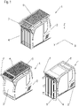
- FIG. 1 1 shows a perspective view of an operator cabin 1 with a housing structure 2 surrounding a workplace for an operator.
- This housing structure 2 typically has an access door on its left and/or right side, through which the operator can enter or leave the operator cabin.
- the housing structure 2 On its front side, the housing structure 2 typically has a receptacle 3 for a front pane, through which the operator can look while carrying out his operating activity.
- a front grille 4 When performing dangerous work, in which rocks or parts of buildings to be demolished may fall onto the operator's cab, it is necessary to increase the safety of the operator to protect the front of the operator's cab with a front grille 4 .
- the same also applies to the roof section 6 of the operator's cabin 2, which can also have a recess for a skylight.
- the roof grille itself 5 is also pivotably arranged on the same axis of rotation 7 that allows the front grille 4 to be pivoted onto the upper side of the roof grille 5 . If the operator's cab or the working machine connected to the operator's cab is to be transported, it is of great importance to reduce the overall height of the working machine or the operator's cab. Thus, when loading the working machine or the operator's cab, it is ensured that the transport height is minimized and fewer height restrictions have to be observed when transporting the working machine or the operator's cab.
- the transport mode of the operator's cabin is shown in the lower right figure 1 shown.
- the invention also encompasses the automatic movement of the grids into their respective positions.
- a drive device can be provided which moves the front grille 4 or the roof grille 5 out of its respective protective position.
- FIG. 2 shows a further embodiment of the present invention, in which, after pivoting the front grille 4 onto the upper side of the roof grille 5, the grilles 4, 5 stacked on top of one another are folded down to the right-hand side of the operator's cabin 2.
- the axis of rotation of the front grille 4 can be produced via a connecting section with the roof grille 5 , the roof grille 5 itself having an axis of rotation running in the longitudinal direction Y of the operator's cab, which is fastened to the operator's cab 2 .
- This is used to pivot the two grids 4 , 5 stacked on top of one another by about 270° from the roof section 6 of the operator's cabin 2 to a right-hand side section of the operator's cabin 2 . It is also possible in this way to reduce the overall height of the operator's cab for a transport mode and at the same time to improve front visibility by folding away the front grille 4 onto the side of the roof grille 5 facing away from the operator's cab 2 .
- 3 12 shows a further embodiment of the present invention, in which the front grille 4 is again pivoted onto the upper side of the roof grille 5 via an axis of rotation running in the width direction of the operator's cab 2 .
- a parallelogram deflection now takes place in which the horizontal alignment of the two gratings 4, 5 stacked one on top of the other is not changed.
- FIG. 4 12 shows a further embodiment of the present invention, in which the front grille 4 is again pivoted onto the upper side of the roof grille 5 via a rotation axis running in the width direction. This is followed by a parallelogram deflection of the two grids arranged one above the other, so that they are no longer arranged above a roof section of the operator's cabin. From this state, there is a pivoting towards a rear side of the operator's cab 2, so that the two grilles are now arranged approximately parallel to the previously assumed protective position of the front grille on the rear of the operator's cab 2. This represented a particularly space-saving storage option for the two grids.
- the Figures 5 and 6 each show only one lattice, with the presence of front lattice 4 and roof lattice 5, the kinematics of the movement for both lattices 4, 5 being identical.
- FIG 5 grid shown as a front grille 4 it is in the left representation of the figure 5 in its protective position.
- the front grille 4 By rotating upwards by approximately 90°, the front grille 4 is now in an approximately horizontal alignment, so that it can be moved into the area above the roof section 6 of the operator's cabin 2 by means of a translational movement or by pushing.
- Is the grille the front grille shows figure 5 So the change from the protective position of the front grille 4 in the front visibility mode.
- the figure 5 shown lattice the roof lattice 5 the change from the transport mode is shown in the protective position of the roof lattice 5.
- FIG. 12 again shows a lattice, which is shifted from the roof section 6 via a sliding movement forwards towards the operator's cabin and by folding it down in relation to an axis of rotation running in the width direction of the operator's cabin 2, which is arranged in the upper area or above the operator's cabin 2, in front of the front the operator's cabin 2 is foldable.
- this is the transition from the front visibility mode for protection.
- the grid shown is the roof grid, this is the transition from the protective position to a transport mode.
- FIG. 7 shows a further embodiment of the present invention, with which, in a first step, the roof grille 5 no longer remains in its protective position, but the roof grille 5 is pivoted in front of the front grille 4 via a pivot axis running in the width direction of the operator's cab.
- the two grids 4, 5, which are now aligned parallel to one another can be pivoted via a further axis of rotation, which also runs in the width direction of the operator's cab 2 and is arranged in the lower area of the operator's cab or under the operator's cab, so that the two are parallel arranged lattice fold down forward and are preferably aligned horizontally.
- the two grids can be pushed into a receiving space arranged below the operator's cabin.
- the kinematics of the two lattice movements can be effected by a first hinge connection of the roof lattice and front lattice 4 so that the roof lattice 5 can be pivoted to the front side of the front lattice 4 .
- the front grille itself then has a swivel connection with the operator's cabin in the lower area, so that the two grilles 4, 5 aligned parallel to one another can be swiveled down and forward together.
- the two grids can then be slid into the receiving space located below the operator's cabin via rails or another sliding system.
- FIG. 8 12 shows another embodiment of the present invention, in which the front grille 4 is again pivoted onto the upper side of the roof grille 5 via an axis of rotation running in the width direction of the operator's cab 2 .
- Another Rotation of the two parallel gratings 4, 5 by about 270° then leads to the two gratings being applied to the rear of the operator's cab 2.
- the axes of rotation can be implemented, for example, by a hinge connection between the roof grating 5 and the front grating 4 and a hinge connection between the roof grating 5 and the operator's cab be.
- fastening means can preferably be provided in order to prevent the front grille 4 from pivoting away from the roof grille 5 in an uncontrolled manner when it is turned over to the rear of the operator's cabin 2.
- FIG. 9 shows a further embodiment of the present invention, in which the front grille cannot be placed on the upper side of the roof grille 5 by a pivoting movement of 270°, but is only folded away upwards and forwards by 90° in a first step.
- the axis of rotation is located in a front upper section of the operator's cab 2 or is located above the operator's cab 2 in the front area. If, in a first step, the front grille 4 is now aligned horizontally, the front grille 4 can be stacked on the roof grille 5 via a one-dimensional translational movement.
- the subsequent pivoting of the two grids 4, 5 stacked on top of one another towards a rear side of the operator's cabin 2 then takes place again via a pivot connection of the roof grid 5 to the operator's cabin 2.
- 10 14 shows a further embodiment of the present invention, in which the front grille 4 is again pivoted onto the upper side of the roof grille 5 via a rotation of 270° along an axis of rotation running in the width direction of the operator's cab 2 .
- FIG. 11 shows a further embodiment of the present invention, in which the two grids 4, 5 are not kept in a common receiving space or in parallel alignment with one another.
- On the left of the 11 one sees the front grille 4 and the roof grille 5 in their protective position.
- Each grid is pivoted away from its protective position via an axis of rotation running parallel to the width direction of the drive cabin.
- the axis of rotation of the front grille 4 runs in the lower area or below the operator's cab, the axis of rotation of the roof grille 5 running in the rear upper area or above the operator's cab.
- Each of the grilles is swiveled out of its protective position by 90° and then moved under or behind the operator's cabin in a subsequent step. Accordingly, the separate pivoting away of the respective lattice from its protective position is possible here, without there being any restrictions for the other lattice.
- FIG. 12 shows a further embodiment for transferring the front grille 4 to the top of the roof grille 5.
- the front grille is pivoted by about 45° in the upper area of the operator's cabin transversely to the operator's cabin of the current axis of rotation, then pushed away upwards so that the front grille 4 is away from the Roof lattice 5 is arranged and rotated 45 ° down so that it rests on top of the roof lattice 5.
- 45° is only of an exemplary nature and that other angle values can also be used for a corresponding use of the idea. In the present case, only the folding movement, the subsequent one-dimensional displacement and the subsequent folding down of the front grille are decisive.
- the 13 shows a further embodiment of the present invention, in which each of the two grids 4, 5 is connected to the operator's cabin via a rail system.
- the rail system runs from the roof section 6 and extends to the front section of the operator's cabin 2.
- a curvilinear movement is carried out along a carriage or the rails in two directions. It can be provided that both the front grille 4 and the roof grille 5 via a have a separate pair of rails or a separate rail for moving the associated grid.
Landscapes
- Engineering & Computer Science (AREA)
- Mechanical Engineering (AREA)
- Chemical & Material Sciences (AREA)
- Combustion & Propulsion (AREA)
- Transportation (AREA)
- Mining & Mineral Resources (AREA)
- Civil Engineering (AREA)
- General Engineering & Computer Science (AREA)
- Structural Engineering (AREA)
- Body Structure For Vehicles (AREA)
Applications Claiming Priority (1)
| Application Number | Priority Date | Filing Date | Title |
|---|---|---|---|
| DE102021103321.7A DE102021103321A1 (de) | 2021-02-12 | 2021-02-12 | Bedienerkabine mit Schutzgitter |
Publications (1)
| Publication Number | Publication Date |
|---|---|
| EP4043644A1 true EP4043644A1 (de) | 2022-08-17 |
Family
ID=80445598
Family Applications (1)
| Application Number | Title | Priority Date | Filing Date |
|---|---|---|---|
| EP22155564.2A Withdrawn EP4043644A1 (de) | 2021-02-12 | 2022-02-08 | Bedienerkabine mit schutzgitter |
Country Status (4)
| Country | Link |
|---|---|
| US (1) | US20220259819A1 (zh) |
| EP (1) | EP4043644A1 (zh) |
| CN (1) | CN114919669A (zh) |
| DE (1) | DE102021103321A1 (zh) |
Cited By (1)
| Publication number | Priority date | Publication date | Assignee | Title |
|---|---|---|---|---|
| CN117465564A (zh) * | 2023-12-28 | 2024-01-30 | 高邮市迅达工程机械集团有限公司 | 一种工程车辆驾驶室以及工程车辆 |
Families Citing this family (1)
| Publication number | Priority date | Publication date | Assignee | Title |
|---|---|---|---|---|
| DE102023107102A1 (de) | 2023-03-21 | 2024-09-26 | Echle Hartstahl Gmbh | Schutzdach für eine Arbeitsfahrzeugkabine |
Citations (7)
| Publication number | Priority date | Publication date | Assignee | Title |
|---|---|---|---|---|
| JPH09228422A (ja) * | 1996-02-22 | 1997-09-02 | Hitachi Constr Mach Co Ltd | 建設機械運転室のガード |
| US20040245755A1 (en) * | 2002-08-20 | 2004-12-09 | Eiji Akahane | Shutter type guard apparatus for construction machine |
| JP2006177117A (ja) * | 2004-12-24 | 2006-07-06 | Kobelco Contstruction Machinery Ltd | 建設機械のキャビンガード装置 |
| CN202248036U (zh) * | 2011-08-22 | 2012-05-30 | 岳立辉 | 可隐藏的驾驶室前玻璃防护网 |
| KR20120071647A (ko) * | 2010-12-23 | 2012-07-03 | 두산인프라코어 주식회사 | 건설중장비의 캐빈 윈도우 가드 장치 |
| DE102014105868A1 (de) * | 2014-04-25 | 2015-10-29 | Jürgen Wolf | Schutzvorrichtung für eine Fahrerkabine eines Nutzfahrzeugs |
| CN104499528B (zh) * | 2014-12-18 | 2017-04-12 | 贵州詹阳动力重工有限公司 | 一种液压挖掘机驾驶室滑移式防护网 |
Family Cites Families (7)
| Publication number | Priority date | Publication date | Assignee | Title |
|---|---|---|---|---|
| JPH08109658A (ja) | 1994-10-13 | 1996-04-30 | Yutani Heavy Ind Ltd | 建設機械のキャブガード |
| KR100689292B1 (ko) * | 2005-06-01 | 2007-03-02 | 볼보 컨스트럭션 이키프먼트 홀딩 스웨덴 에이비 | 중장비 운전실에 장착되는 운전자 보호구조물 |
| DE102012102140A1 (de) * | 2012-03-12 | 2013-09-12 | Echle Hartstahl Gmbh | Kabinenschutz |
| US20150123428A1 (en) * | 2012-06-18 | 2015-05-07 | Volvo Construction Equipment Ab | Cab protection apparatus for construction machinery |
| JP6079193B2 (ja) | 2012-12-12 | 2017-02-15 | コベルコ建機株式会社 | 建設機械のキャブヘッドガード装置 |
| KR200476695Y1 (ko) | 2014-07-17 | 2015-03-24 | 고상순 | 중장비의 안전망 장치 |
| CN204641913U (zh) | 2015-02-03 | 2015-09-16 | 天津三宇车体制造有限公司 | 一种工程施工车辆的驾驶室 |
-
2021
- 2021-02-12 DE DE102021103321.7A patent/DE102021103321A1/de active Pending
-
2022
- 2022-02-08 EP EP22155564.2A patent/EP4043644A1/de not_active Withdrawn
- 2022-02-10 CN CN202210124492.XA patent/CN114919669A/zh active Pending
- 2022-02-11 US US17/669,848 patent/US20220259819A1/en not_active Abandoned
Patent Citations (7)
| Publication number | Priority date | Publication date | Assignee | Title |
|---|---|---|---|---|
| JPH09228422A (ja) * | 1996-02-22 | 1997-09-02 | Hitachi Constr Mach Co Ltd | 建設機械運転室のガード |
| US20040245755A1 (en) * | 2002-08-20 | 2004-12-09 | Eiji Akahane | Shutter type guard apparatus for construction machine |
| JP2006177117A (ja) * | 2004-12-24 | 2006-07-06 | Kobelco Contstruction Machinery Ltd | 建設機械のキャビンガード装置 |
| KR20120071647A (ko) * | 2010-12-23 | 2012-07-03 | 두산인프라코어 주식회사 | 건설중장비의 캐빈 윈도우 가드 장치 |
| CN202248036U (zh) * | 2011-08-22 | 2012-05-30 | 岳立辉 | 可隐藏的驾驶室前玻璃防护网 |
| DE102014105868A1 (de) * | 2014-04-25 | 2015-10-29 | Jürgen Wolf | Schutzvorrichtung für eine Fahrerkabine eines Nutzfahrzeugs |
| CN104499528B (zh) * | 2014-12-18 | 2017-04-12 | 贵州詹阳动力重工有限公司 | 一种液压挖掘机驾驶室滑移式防护网 |
Cited By (2)
| Publication number | Priority date | Publication date | Assignee | Title |
|---|---|---|---|---|
| CN117465564A (zh) * | 2023-12-28 | 2024-01-30 | 高邮市迅达工程机械集团有限公司 | 一种工程车辆驾驶室以及工程车辆 |
| CN117465564B (zh) * | 2023-12-28 | 2024-03-22 | 高邮市迅达工程机械集团有限公司 | 一种工程车辆驾驶室以及工程车辆 |
Also Published As
| Publication number | Publication date |
|---|---|
| US20220259819A1 (en) | 2022-08-18 |
| CN114919669A (zh) | 2022-08-19 |
| DE102021103321A1 (de) | 2022-08-18 |
Similar Documents
| Publication | Publication Date | Title |
|---|---|---|
| EP2166154B2 (de) | Baumaschine mit einem schutzdachaufbau für den führerstand | |
| EP0909855B1 (de) | Laderfahrzeug | |
| EP4043644A1 (de) | Bedienerkabine mit schutzgitter | |
| EP3489416B1 (de) | Bodenbearbeitungsmaschine mit gemeinsam mit einem schutzdach anheb- und absenkbarer scheibenanordnung und verfahren zur veränderung der höhenabmessung dieser bodenbearbeitungsmaschine | |
| EP0916004A1 (de) | Strassenbaumaschinen zum bearbeiten von fahrbahnen | |
| DE2501798C3 (de) | Schwenkbare Lastwagen-Bordwand | |
| DE3020438A1 (de) | Spreizrahmenanordnung fuer torlader u.dgl. | |
| DE102012021379B4 (de) | Bodenfräsmaschine mit schwenkbarer Fahreinrichtung | |
| DE102004059943A1 (de) | Vortriebs- oder Gewinnungsmaschine mit Ankerbohr- und -setzeinrichtungen | |
| DE69203917T2 (de) | Werkzeugwechselvorrichtung einer Erdbaumaschine. | |
| EP2399860B1 (de) | Klappbares Fahrerschutzdach | |
| EP2944490B1 (de) | Transportfahrzeug für stückgut | |
| DE2015792C2 (de) | Als Ackerschlepper einzusetzendes landwirtschaftliches Fahrzeug | |
| DE69226516T2 (de) | Umklappbare frachtrampe | |
| EP3027476A1 (de) | Landfahrzeug | |
| EP3416912B1 (de) | Höhenzugang-auslegereinheit für eine mobile höhenzugangsmaschine, eine höhenzugangsmaschine und eine verwendung der höhenzugang-auslegereinheit | |
| DE102020130653A1 (de) | Mobile Arbeitsmaschine mit einem höhenverstellbaren Fahrerschutzdach | |
| DE2739325A1 (de) | Verladefahrzeug | |
| DE19932612A1 (de) | Verschwenkbarer Geräteanbau eines Kraftfahrzeugs | |
| DE102017113099B4 (de) | Kupplungsbolzenentnahmevorrichtung und mit dieser versehene arbeitsmaschine | |
| DE102014117583A1 (de) | Mäheinrichtung und Verfahren zum Betreiben einer Mäheinrichtung | |
| DE102012023357A1 (de) | Vorrichtung und Verfahren zur Positionierung und Arretierung von Ergänzungsteilen für den Kranbetrieb | |
| DE102014014704B4 (de) | Bodenfräsmaschine und Verfahren zum Verschwenken einer Fahreinrichtung einer Bodenfräsmaschine | |
| DE10225528A1 (de) | Entgratpresse | |
| DE112012005568T5 (de) | Angetriebenes Bedienerzugangssystem |
Legal Events
| Date | Code | Title | Description |
|---|---|---|---|
| PUAI | Public reference made under article 153(3) epc to a published international application that has entered the european phase |
Free format text: ORIGINAL CODE: 0009012 |
|
| STAA | Information on the status of an ep patent application or granted ep patent |
Free format text: STATUS: THE APPLICATION HAS BEEN PUBLISHED |
|
| AK | Designated contracting states |
Kind code of ref document: A1 Designated state(s): AL AT BE BG CH CY CZ DE DK EE ES FI FR GB GR HR HU IE IS IT LI LT LU LV MC MK MT NL NO PL PT RO RS SE SI SK SM TR |
|
| P01 | Opt-out of the competence of the unified patent court (upc) registered |
Effective date: 20230512 |
|
| STAA | Information on the status of an ep patent application or granted ep patent |
Free format text: STATUS: THE APPLICATION IS DEEMED TO BE WITHDRAWN |
|
| 18D | Application deemed to be withdrawn |
Effective date: 20230218 |