EP4037061B1 - Chargeur pour batterie portable - Google Patents
Chargeur pour batterie portable Download PDFInfo
- Publication number
- EP4037061B1 EP4037061B1 EP20869193.1A EP20869193A EP4037061B1 EP 4037061 B1 EP4037061 B1 EP 4037061B1 EP 20869193 A EP20869193 A EP 20869193A EP 4037061 B1 EP4037061 B1 EP 4037061B1
- Authority
- EP
- European Patent Office
- Prior art keywords
- charger
- battery
- inclined surface
- disposed
- control device
- Prior art date
- Legal status (The legal status is an assumption and is not a legal conclusion. Google has not performed a legal analysis and makes no representation as to the accuracy of the status listed.)
- Active
Links
- 230000000630 rising effect Effects 0.000 claims description 7
- 230000000694 effects Effects 0.000 description 20
- 238000010586 diagram Methods 0.000 description 13
- 238000009434 installation Methods 0.000 description 3
- 239000000758 substrate Substances 0.000 description 3
- 238000009825 accumulation Methods 0.000 description 2
- 230000001154 acute effect Effects 0.000 description 2
- 239000000470 constituent Substances 0.000 description 2
- XLYOFNOQVPJJNP-UHFFFAOYSA-N water Substances O XLYOFNOQVPJJNP-UHFFFAOYSA-N 0.000 description 2
- HBBGRARXTFLTSG-UHFFFAOYSA-N Lithium ion Chemical compound [Li+] HBBGRARXTFLTSG-UHFFFAOYSA-N 0.000 description 1
- XAGFODPZIPBFFR-UHFFFAOYSA-N aluminium Chemical compound [Al] XAGFODPZIPBFFR-UHFFFAOYSA-N 0.000 description 1
- 229910052782 aluminium Inorganic materials 0.000 description 1
- 229910001416 lithium ion Inorganic materials 0.000 description 1
- 230000004048 modification Effects 0.000 description 1
- 238000012986 modification Methods 0.000 description 1
- 239000011347 resin Substances 0.000 description 1
- 229920005989 resin Polymers 0.000 description 1
Images


Classifications
-
- H—ELECTRICITY
- H01—ELECTRIC ELEMENTS
- H01M—PROCESSES OR MEANS, e.g. BATTERIES, FOR THE DIRECT CONVERSION OF CHEMICAL ENERGY INTO ELECTRICAL ENERGY
- H01M10/00—Secondary cells; Manufacture thereof
- H01M10/42—Methods or arrangements for servicing or maintenance of secondary cells or secondary half-cells
- H01M10/44—Methods for charging or discharging
-
- H—ELECTRICITY
- H02—GENERATION; CONVERSION OR DISTRIBUTION OF ELECTRIC POWER
- H02J—CIRCUIT ARRANGEMENTS OR SYSTEMS FOR SUPPLYING OR DISTRIBUTING ELECTRIC POWER; SYSTEMS FOR STORING ELECTRIC ENERGY
- H02J7/00—Circuit arrangements for charging or depolarising batteries or for supplying loads from batteries
- H02J7/0042—Circuit arrangements for charging or depolarising batteries or for supplying loads from batteries characterised by the mechanical construction
-
- B—PERFORMING OPERATIONS; TRANSPORTING
- B60—VEHICLES IN GENERAL
- B60L—PROPULSION OF ELECTRICALLY-PROPELLED VEHICLES; SUPPLYING ELECTRIC POWER FOR AUXILIARY EQUIPMENT OF ELECTRICALLY-PROPELLED VEHICLES; ELECTRODYNAMIC BRAKE SYSTEMS FOR VEHICLES IN GENERAL; MAGNETIC SUSPENSION OR LEVITATION FOR VEHICLES; MONITORING OPERATING VARIABLES OF ELECTRICALLY-PROPELLED VEHICLES; ELECTRIC SAFETY DEVICES FOR ELECTRICALLY-PROPELLED VEHICLES
- B60L53/00—Methods of charging batteries, specially adapted for electric vehicles; Charging stations or on-board charging equipment therefor; Exchange of energy storage elements in electric vehicles
- B60L53/80—Exchanging energy storage elements, e.g. removable batteries
-
- B—PERFORMING OPERATIONS; TRANSPORTING
- B60—VEHICLES IN GENERAL
- B60L—PROPULSION OF ELECTRICALLY-PROPELLED VEHICLES; SUPPLYING ELECTRIC POWER FOR AUXILIARY EQUIPMENT OF ELECTRICALLY-PROPELLED VEHICLES; ELECTRODYNAMIC BRAKE SYSTEMS FOR VEHICLES IN GENERAL; MAGNETIC SUSPENSION OR LEVITATION FOR VEHICLES; MONITORING OPERATING VARIABLES OF ELECTRICALLY-PROPELLED VEHICLES; ELECTRIC SAFETY DEVICES FOR ELECTRICALLY-PROPELLED VEHICLES
- B60L58/00—Methods or circuit arrangements for monitoring or controlling batteries or fuel cells, specially adapted for electric vehicles
- B60L58/10—Methods or circuit arrangements for monitoring or controlling batteries or fuel cells, specially adapted for electric vehicles for monitoring or controlling batteries
- B60L58/24—Methods or circuit arrangements for monitoring or controlling batteries or fuel cells, specially adapted for electric vehicles for monitoring or controlling batteries for controlling the temperature of batteries
- B60L58/26—Methods or circuit arrangements for monitoring or controlling batteries or fuel cells, specially adapted for electric vehicles for monitoring or controlling batteries for controlling the temperature of batteries by cooling
-
- H—ELECTRICITY
- H01—ELECTRIC ELEMENTS
- H01M—PROCESSES OR MEANS, e.g. BATTERIES, FOR THE DIRECT CONVERSION OF CHEMICAL ENERGY INTO ELECTRICAL ENERGY
- H01M10/00—Secondary cells; Manufacture thereof
- H01M10/60—Heating or cooling; Temperature control
-
- H—ELECTRICITY
- H01—ELECTRIC ELEMENTS
- H01M—PROCESSES OR MEANS, e.g. BATTERIES, FOR THE DIRECT CONVERSION OF CHEMICAL ENERGY INTO ELECTRICAL ENERGY
- H01M50/00—Constructional details or processes of manufacture of the non-active parts of electrochemical cells other than fuel cells, e.g. hybrid cells
- H01M50/20—Mountings; Secondary casings or frames; Racks, modules or packs; Suspension devices; Shock absorbers; Transport or carrying devices; Holders
- H01M50/249—Mountings; Secondary casings or frames; Racks, modules or packs; Suspension devices; Shock absorbers; Transport or carrying devices; Holders specially adapted for aircraft or vehicles, e.g. cars or trains
-
- H—ELECTRICITY
- H02—GENERATION; CONVERSION OR DISTRIBUTION OF ELECTRIC POWER
- H02J—CIRCUIT ARRANGEMENTS OR SYSTEMS FOR SUPPLYING OR DISTRIBUTING ELECTRIC POWER; SYSTEMS FOR STORING ELECTRIC ENERGY
- H02J7/00—Circuit arrangements for charging or depolarising batteries or for supplying loads from batteries
- H02J7/0029—Circuit arrangements for charging or depolarising batteries or for supplying loads from batteries with safety or protection devices or circuits
- H02J7/00309—Overheat or overtemperature protection
-
- H—ELECTRICITY
- H02—GENERATION; CONVERSION OR DISTRIBUTION OF ELECTRIC POWER
- H02J—CIRCUIT ARRANGEMENTS OR SYSTEMS FOR SUPPLYING OR DISTRIBUTING ELECTRIC POWER; SYSTEMS FOR STORING ELECTRIC ENERGY
- H02J7/00—Circuit arrangements for charging or depolarising batteries or for supplying loads from batteries
- H02J7/0042—Circuit arrangements for charging or depolarising batteries or for supplying loads from batteries characterised by the mechanical construction
- H02J7/0045—Circuit arrangements for charging or depolarising batteries or for supplying loads from batteries characterised by the mechanical construction concerning the insertion or the connection of the batteries
Definitions
- the present invention relates to a charger for a portable battery.
- JP 2013 - 099 200 A discloses a charger in which a battery having a shape elongated in a vertical direction is detachably mounted. The battery is disposed in a manner of standing upright such that it is elongated in the vertical direction in a state in which the battery is mounted in the charger (in a placed state).
- JP H05 - 315 013 A discloses a charger as described in the preamble of claim 1, wherein the further teaching comprises a part of the casing being a triangular holder with an inclined upper surface.
- JP 2002 - 199 597 A discloses a charger similar to that disclosed by JP H05 - 315 013 A , but without any controller element.
- JP 2018 - 092 746 A discloses a receptacle for a portable battery.
- JP H10 - 304 581 A discloses a charger for a portable battery with a drainage hole.
- an object of the present invention is to reduce a height in a vertical direction in a battery-placed state in a charger for a portable battery.
- an aspect of the present invention has the following constitutions.
- the tray has the first inclined surface which is inclined with respect to a horizontal surface and is formed in the length direction of the battery in a state of being placed in the charger, and the second inclined surface which rises from the end portion of the first inclined surface in the height direction of the battery in a state of being placed in the charger and receives the bottom surface of the battery. Therefore, the following effect is exhibited.
- the first inclined surface and the second inclined surface of the tray are obliquely disposed with respect to the vertical direction. For this reason, compared to when the battery is disposed in a manner of standing upright such that it is elongated in the vertical direction in a state in which the battery is mounted in the charger, the height in the vertical direction in a battery-placed state can be reduced.
- control device is disposed below the first inclined surface. Therefore, the following effect is exhibited. Compared to when the control device is disposed above the first inclined surface, the height of the charger in the vertical direction can be reduced. Furthermore, compared to when the control device is disposed on a lateral side of the first inclined surface, an installation area of the charger can be reduced.
- the frame is disposed between the control device and the first inclined surface in the vertical direction, transfer of an impact to the control device occurring when the battery (heavy article) is placed in the tray can be curbed.
- the battery has the grip portion at the end portion in the length direction, and the grip portion is disposed on the upper end side of the first inclined surface.
- the frame is disposed on a side closer to the grip portion than the central portion on the first inclined surface in the length direction. Therefore, the following effect is exhibited.
- the grip portion is disposed on the upper end side of the first inclined surface, compared to when the grip portion is disposed on a lower end side of the first inclined surface, the battery is easily placed in the tray. Furthermore, since the frame is disposed on a side closer to the grip portion than the central portion on the first inclined surface in the length direction, a load on the control device occurring when the battery is placed in the tray can be suitably curbed on a side where the battery is easily placed in the tray.
- the bottom portion of the charger has the recess portion which is recessed downward at a part positioned below the control device. Therefore, the following effect is exhibited. Heat of the control device can escape via a gap between the control device and the recess portion.
- the heat conduction member having a higher heat conductivity than the bottom portion of the charger is disposed in the recess portion. Therefore, the following effect is exhibited.
- Heat of the control device can more effectively escape via the heat conduction member.
- the rib projecting upward is formed on the first inclined surface. Therefore, the following effect is exhibited.
- An impact occurring when the battery is placed on the first inclined surface can be relaxed by the rib.
- the central portion on the first inclined surface in the width direction has a curved surface shape projecting downward. Therefore, the following effect is exhibited.
- Accumulation of heat on a lower surface of the battery (a surface on a side of the first inclined surface) can be curbed.
- the drain hole is formed at the lowest end on the first inclined surface.
- the bottom portion of the charger has the enclosure portion having an opening larger than the drain hole at a part positioned below the drain hole.
- the discharge hole is formed in the enclosure portion. Therefore, the following effect is exhibited.
- Water which has infiltrated into the tray can be suitably discharged via the drain hole and the discharge hole.
- the charger further includes the holding member which holds the charger terminal in a connection direction with respect to the battery. Therefore, the following effect is exhibited.
- the charger terminal can be smoothly connected to the battery by the holding member.
- the frame extends throughout the entirety of the battery in the width direction. Therefore, the following effect is exhibited.
- a charger for a portable battery a charger for a portable battery (mobile battery) used in an electrically-driven motorcycle (saddle-type electric vehicle)
- a charger for a portable battery used in an electrically-driven motorcycle (saddle-type electric vehicle)
- a battery 100 has a rectangular parallelepiped shape.
- the battery 100 is a lithium-ion battery.
- the battery 100 has a pair of first side 101 and second side 102 above and below extending in a width direction V3, and a pair of third side 103 and fourth side 104 on the left and the right extending in a height direction V2 (refer to Fig. 12 ).
- the battery 100 has side surfaces 121 and 122 extending in a length direction V1 (refer to Fig. 12 ).
- the first side 101 has a curved line shape projecting toward a side opposite to the second side 102 (upper side in Fig. 2 ).
- the side surface 121 on a side of the first side 101 (one surface of the battery 100 in the height direction V2) of side surfaces of the battery 100 has a curved surface shape projecting toward a side opposite to the side surface 122 on a side of the second side 102.
- the battery 100 has a grip portion 110 (handle) gripped by a user.
- the grip portion 110 is provided at an end portion of the battery 100 in the length direction V1 (refer to Fig. 12 ).
- the grip portion 110 is provided on a first surface 111 facing one side of the battery 100 in the length direction V1.
- a terminal 106 of the battery 100 (which will hereinafter be simply referred to as "a battery terminal 106") is provided on a second surface 112 (bottom surface) on a side opposite to the first surface 111 in the length direction V1 of the battery 100 (refer to Fig. 12 ).
- the battery terminal 106 is disposed in the vicinity of the side surface 121 (which will hereinafter be referred to as "a first side surface 121”) on a side of the first side 101 of the second surface 112 (refer to Fig. 12 ).
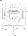
- a charger 1 includes a tray 2 in which the battery 100 is placed, an upper cover 3 which covers a portion of the tray 2 from above, a control device 4 which performs charging control of the battery 100 (refer to Fig. 12 ), a main body frame 5 which constitutes a skeleton of a main body of the charger 1 (refer to Fig. 11 ), a terminal 6 of the charger 1 (which will hereinafter be simply referred to as "a charger terminal 6", refer to Fig. 4 ), a holding member 7 which holds the charger terminal 6 (refer to Fig. 4 ), and an operation mechanism 8 which moves the charger terminal 6 (refer to Fig. 11 ).
- the bottom surface of the charger 1 is formed to be parallel to (horizontally with respect to) the floor surface.
- a depth direction when the charger 1 is installed on the floor surface (a direction orthogonal to the paper illustrated in Fig. 4 ) will be referred to as "a forward-rearward direction", a normal direction (vertical direction) of the floor surface will be referred to as “a vertical direction”, and a direction orthogonal to each of the forward-rearward direction and the vertical direction will be referred to as "a lateral direction (width direction)".
- a forward-rearward direction a normal direction (vertical direction) of the floor surface
- a lateral direction width direction
- an arrow FR indicates the forward side
- an arrow UP indicates the upward side
- an arrow LH indicates the left side, respectively.
- the tray 2 opens upward and forward such that the battery 100 (refer to Fig. 1 ) can be placed therein and taken out.
- the tray 2 includes a bottom surface portion 10 which is formed in the length direction V1 of the battery 100 in a state of being placed in the charger 1, a receiving surface portion 11 which receives a bottom portion of the battery 100, and a pair of left and right side surface portions 12 which face the side surfaces of the battery 100 in the width direction V3.
- the receiving surface portion 11 and the pair of left and right side surface portions 12 rise from the bottom surface portion 10 in the height direction V2 of the battery 100 in a state of being placed in the charger 1 (refer to Fig. 12 ).
- the reference sign 12h indicates a long hole for restricting movement of a lever 60 (turning of a first link 61 around a first pivot shaft 65).
- the bottom surface portion 10 has a first inclined surface 10a which is inclined with respect to the bottom surface of the charger 1.
- the first inclined surface 10a is a placement surface on which the battery 100 is placed.
- the first inclined surface 10a is inclined with respect to a horizontal surface.
- the first inclined surface 10a is formed in the length direction V1 of the battery 100 in a state of being placed in the charger 1.
- the first inclined surface 10a is a surface facing the side surface 122 (which will hereinafter be referred to as "a second side surface 122") on a side of the second side 102 of the battery 100.
- the first inclined surface 10a is inclined such that the angle formed between the first inclined surface 10a and the bottom surface of the charger 1 becomes an acute angle smaller than 45°.
- a central portion on the first inclined surface 10a in the width direction V3 has a curved surface shape projecting downward.
- the first inclined surface 10a is curved such that a center position in the width direction V3 becomes the lowermost position, and outer end positions in the width direction V3 become the uppermost positions.
- the first inclined surface 10a in its entirety has an arc shape projecting downward.
- Ribs 10b projecting upward are formed on the first inclined surface 10a.
- the ribs 10b extend in the forward-rearward direction.
- a plurality of ribs 10b are disposed at intervals in the width direction V3. Sizes of the intervals between two ribs 10b adjacent to each other in the width direction V3 are the same as each other.
- Upper ends of the plurality of ribs 10b in the vertical direction are positioned at the same positions. In a state in which the battery 100 is placed in the tray 2 (which will hereinafter be referred to as "a placed state"), the upper end of each of the ribs 10b comes into contact with the second side surface 122 of the battery 100.
- a drain hole 10h is formed at a lowest end 14b on the first inclined surface 10a.
- the drain hole 10h is disposed at the center of a rear end portion on the first inclined surface 10a in the width direction V3 (refer to Fig. 5 ).
- the drain hole 10h opens at a rear end portion on the first inclined surface 10a in the vertical direction.
- a bottom portion of the charger 1 has an enclosure portion 13 at a part positioned below the drain hole 10h.
- the enclosure portion 13 has a bottomed tubular shape with an opening larger than the drain hole 10h.
- the enclosure portion 13 has an opening larger than a tubular portion having the drain hole 10h.
- the enclosure portion 13 has a ring shape extending in the width direction V3 (refer to Fig. 6 ).
- discharge holes 13h are formed in a bottom portion of the enclosure portion 13.
- a pair of left and right discharge holes 13h are disposed with an interval therebetween in the width direction V3.
- the pair of left and right discharge holes 13h are disposed at both ends of the enclosure portion 13 in the width direction V3.
- the receiving surface portion 11 has a second inclined surface 11a which is inclined with respect to the bottom surface of the charger 1.
- the second inclined surface 11a rises from the end portion (rear lower end portion) on the first inclined surface 10a in the height direction V2 of the battery 100 in a placed state.
- the second inclined surface 11a is a part receiving the second surface 112 of the battery 100.
- the second inclined surface 11a is inclined such that it is orthogonal to the first inclined surface 10a.
- the second inclined surface 11a is inclined such that the angle formed between the second inclined surface 11a and the bottom surface of the charger 1 becomes an acute angle larger than 45°.
- upper end positions of the side surface portions 12 are positioned below an upper end position of the battery 100 in a placed state.
- upper end edges of the side surface portions 12 are inclined such that they are positioned downward toward the front side from the upper end positions.
- front end edges of the side surface portions 12 are inclined such that they are positioned forward toward a lower side from front ends at the upper end edges.
- the grip portion 110 of the battery 100 in a placed state is disposed on an upper end side on the first inclined surface 10a.
- the upper ends at the front end edges of the side surface portions 12 are positioned behind a front end position of the grip portion 110 of the battery 100 in a placed state.
- a portion of the grip portion 110 of the battery 100 in a placed state is exposed from the side surface portions 12.
- the front end portion of the battery 100 in a placed state does not protrude outward beyond the tray 2.
- the reference sign KL indicates a perpendicular line (imaginary vertical line) passing through the front end portion of the tray 2.
- the front end portion of the battery 100 in a placed state is positioned on a side inward from the perpendicular line KL (charger 1 side).
- the tray 2 has a recess portion 14 (which will hereinafter be referred to as "a placement surface recess portion 14") which is recessed downward beyond the first inclined surface 10a (placement surface) at the end portion on a side of the grip portion 110 of the battery 100 in a placed state.
- the placement surface recess portion 14 has a size to an extent that a portion of a hand (finger) of a user enters.
- the placement surface recess portion 14 is disposed at the center of the tray 2 in the width direction V3 (refer to Fig. 4 ).
- the placement surface recess portion 14 has a trapezoidal external shape having an upper base on the rear side and a lower base longer than the upper base in the width direction V3 on the front side (refer to Fig. 5 ).
- a bottom surface 14a of the placement surface recess portion 14 is inclined such that it is positioned downward toward the front side.
- the lowest end 14b of the placement surface recess portion 14 is positioned above the upper end of the control device 4 (refer to Fig. 12 ).
- the reference sign 14c indicates a rising portion which rises upward toward the first inclined surface 10a from a rear end on the bottom surface 14a of the placement surface recess portion 14.
- a wall portion 15 projecting upward beyond the first inclined surface 10a is provided at a boundary portion between the placement surface recess portion 14 and the first inclined surface 10a.
- the wall portion 15 is a part protruding upward beyond the first inclined surface 10a from an upper end of the rising portion 14c.
- the upper end edge of the wall portion 15 linearly extends in the width direction V3 (refer to Fig. 4 ).
- the wall portion 15 is connected to a front end of the rib 10b of the plurality of ribs 10b positioned in the vicinity of the center in the width direction V3 (refer to Fig. 5 ).
- the position of the upper end of the wall portion 15 in the vertical direction is the same position as the positions of the upper ends of the ribs 10b in the vertical direction.
- the upper end of the wall portion 15 comes into contact with the second side surface 122 of the battery 100 in a placed state together with each of the ribs 10b.
- the upper cover 3 is provided at an upper rear portion of the charger 1.
- the upper cover 3 covers a portion of the bottom surface portion 10 and the pair of left and right side surface portions 12 of the tray 2 from above (refer to Fig. 12 ).
- the upper cover 3 covers the charger terminal 6 and the holding member 7 from above.
- an upper edge of the upper cover 3 is inclined such that it is positioned downward toward the rear side.
- an opening edge portion 3a of the upper cover 3 has a curved surface shape along the first side surface 121 of the battery 100 (refer to Fig. 2 ).
- the control device 4 is disposed below the first inclined surface 10a of the tray 2.
- the control device 4 has a rectangular shape extending in the width direction V3.
- the control device 4 includes a plurality of control substrates for performing charging control of the battery 100.
- the control substrates may be disposed such that control circuits for performing charging control of the battery 100 are directed toward the inward side.
- fins or heat sinks may be provided on outer surfaces of the control substrates.
- the bottom portion of the charger 1 has a recess portion 16 which is recessed downward (which will hereinafter be referred to as "a bottom surface recess portion 16") at a part positioned below the control device 4.
- a bottom surface recess portion 16 When viewed in the vertical direction, the bottom surface recess portion 16 is disposed at a position overlapping the control device 4.
- the bottom surface recess portion 16 When viewed in the vertical direction, the bottom surface recess portion 16 has a rectangular external shape larger than the external shape of the control device 4.
- a heat conduction member 20 is disposed in the bottom surface recess portion 16 having a higher heat conductivity than the bottom portion of the charger 1.
- the bottom portion of the charger 1 is made of a resin.
- the heat conduction member 20 is an aluminum sheet.
- the main body frame 5 includes a front frame 30 which is positioned at a front portion of the charger 1, and a rear frame 40 which is positioned at a rear portion of the charger 1.
- the front frame 30 When viewed in the vertical direction, the front frame 30 includes a frame body 31 having a rectangular frame shape (refer to Fig. 6 ), a pair of left and right columnar bodies 32 extending in the vertical direction, and a cross pipe 33 (frame) extending in the width direction V3.
- a frame body 31 having a rectangular frame shape (refer to Fig. 6 )
- a pair of left and right columnar bodies 32 extending in the vertical direction
- a cross pipe 33 (frame) extending in the width direction V3.
- the frame body 31 has a rectangular frame shape larger than the external shape of the control device 4.
- the control device 4 is accommodated on the inward side of the frame body 31.
- the reference sign 34 indicates a pair of left and right front flange portions which protrude forward from an upper front edge of the frame body 31
- the reference sign 35 indicates a pair of left and right rear flange portions which protrude rearward from an upper rear edge of the frame body 31
- the reference sign 18 indicates boss portions of the bottom portion of the charger 1 which are disposed at positions respectively overlapping the flanges 34 and 35 in a top view.
- each of the flange portions 34 and 35 is coupled to each of boss portions 18 using a fastening member such as a bolt.
- the columnar bodies 32 are disposed on the outward sides of the frame body 31 in the width direction V3. Lower portions of the columnar bodies 32 are coupled to side portions of the frame body 31 in the width direction V3.
- the cross pipe 33 is disposed on the upper side of the control device 4.
- the cross pipe 33 extends throughout the entirety of the battery 100 in a placed state in the width direction V3 (refer to Fig. 12 ).
- the length of the cross pipe 33 is longer than that of the control device 4 (refer to Fig. 6 ).
- Left and right end portions of the cross pipe 33 are coupled to upper and lower central portions of the columnar bodies 32 (refer to Fig. 11 ).
- the cross pipe 33 is disposed between the control device 4 and the first inclined surface 10a in the vertical direction.
- the cross pipe 33 is disposed on a side closer to the grip portion 110 of the battery 100 in a placed state than the central portion on the first inclined surface 10a in the length direction V1.
- the cross pipe 33 is disposed behind and in the vicinity of the rising portion 14c of the placement surface recess portion 14.
- the cross pipe 33 is disposed at a position overlapping a central portion of the control device 4 in the forward-rearward direction.
- the reference sign 37 indicates a pair of left and right brackets which protrude forward from a front portion of the cross pipe 33
- the reference sign 19 (refer to Fig. 5 ) indicates boss portions of lower portion on the first inclined surface 10a which are disposed at positions respectively overlapping the brackets 37 in a top view.
- each of the brackets 37 is coupled to each of the boss portions 19 using a fastening member 38 such as a bolt.
- the rear frame 40 is disposed behind the front frame 30.
- the rear frame 40 is disposed below the upper cover 3.
- the rear frame 40 includes a pair of left and right side wall portions 41 which extend in the vertical direction, and a width-direction-extending portion 42 which extends in the width direction V3 (refer to Fig. 6 ).
- the pair of left and right side wall portions 41 and the width-direction-extending portion 42 are integrally formed using the same members.
- the pair of left and right side wall portions 41 and the width-direction-extending portion 42 may be integrally formed using different members.
- the side wall portions 41 are disposed on the outward sides of the rear portion of the tray 2 (rear portion of the battery 100 in a placed state) in the width direction V3 (refer to Fig. 12 ). In a side view of Fig. 11 , the side wall portions 41 have external shapes of which lengths in the forward-rearward direction become longer toward the lower side.
- the side wall portions 41 have a pair of upper and lower circular opening portions 41h. Lower end portions of the side wall portions 41 are coupled to the bottom portion of the charger 1 using a fastening member such as a bolt.
- the width-direction-extending portion 42 is disposed on the upper side of the rear portion of the tray 2 (rear portion of the battery 100 in a placed state) (refer to Fig. 12 ).
- the width-direction-extending portion 42 is disposed between the charger terminal 6 and the upper cover 3 in the vertical direction (refer to Fig. 12 ).
- Left and right end portions of the width-direction-extending portion 42 are coupled to upper ends of the side wall portions 41.
- the width-direction-extending portion 42 has a curved shape along the opening edge portion 3a of the upper cover 3.
- the width-direction-extending portion 42 is inclined downward to the rear along the upper cover 3.
- the holding member 7 holds the charger terminal 6 in a connection direction with respect to the battery 100 (arrow J1 direction in the diagram).
- the holding member 7 has a U-shape opening forward.
- the holding member 7 includes a pair of left and right side arm portions 50 which extend in the forward-rearward direction, and a support arm portion 51 which supports the charger terminal 6.
- the pair of left and right side arm portions 50 and support arm portion 51 are integrally formed using the same members.
- the pair of left and right side arm portions 50 and support arm portion 51 may be integrally formed using different members.
- the side arm portions 50 are disposed on the inward sides of the side wall portions 41 of the rear frame 40 in the width direction V3. In a side view of Fig. 11 , the side arm portions 50 extend such that they are positioned downward toward the rear side along the inclination of the battery 100 in a placed state.
- the side arm portions 50 have long holes 50h (guide holes).
- the long holes 50h extend in a direction in which the side arm portions 50 extend.
- the side arm portions 50 are supported by a shaft (not illustrated) in the width direction V3 of the charger 1 via the long holes 50h.
- the support arm portion 51 is disposed on the rear side of the charger terminal 6.
- the support arm portion 51 extends in the width direction V3.
- Left and right end portions of the support arm portion 51 are coupled to rear ends of the side arm portions 50.
- the reference sign 52 indicates a pair of left and right support pins which protrude forward from the support arm portion 51
- the reference sign 53 indicates biasing members (elastic members) such as springs which are respectively provided in the support pins.
- the charger terminal 6 At a connection position (refer to the solid line in Fig. 12 ) where the charger terminal 6 is connected to the battery 100, the charger terminal 6 is biased by the biasing member 53 in the arrow J1 direction in the diagram toward the battery terminal 106. That is, the biasing member 53 biases the charger terminal 6 in the connection direction with respect to the battery 100 at the connection position.
- the operation mechanism 8 includes the lever 60 (operation portion) which allows movement between the connection position where the charger terminal 6 is connected to the battery terminal 106 (which will hereinafter be simply referred to as "a connection position", refer to the solid line in Fig. 12 ) and a retreat position for retreat from the battery terminal 106 (which will hereinafter be referred to as "a retreat position”, refer to the two-dot dashed line in Fig. 12 ).
- connection position means a position where the charger terminal 6 is fitted into the terminal 106 of the battery 100 in a placed state.
- the retreat position means a position where the charger terminal 6 has separated from the terminal 106 of the battery 100 in a placed state.
- the operation mechanism 8 moves the charger terminal 6 between the connection position and the retreat position using a link mechanism. As illustrated in Fig. 11 , the operation mechanism 8 includes the lever 60 (operation portion); and the first link 61, a second link 62, and a third link 63 constituting the link mechanism.
- the lever 60 is disposed on the outward side of the charger 1 from the placement surface recess portion 14.
- the lever 60 has a U-shape opening upward at the center of the tray 2 in the width direction V3 (refer to Fig. 4 ).
- the lever 60 includes a first extending portion 60a which extends in the width direction V3, and a second extending portion 60b which is inclined and extends such that it is positioned upward toward the outward side in the width direction V3 from left and right end portions of the first extending portion 60a.
- the lever 60 can turn around a shaft in the width direction V3 of the charger 1 (around the first pivot shaft 65).
- the lever 60 is constituted such that it turns downward around the shaft due to a load from above.
- the lever 60 is constituted such that it turns upward around the shaft due to a load from below.
- the lever 60 at the connection position (refer to the two-dot dashed line in Fig. 11 ) is in a state in which the lever 60 has turned further upward around the shaft than the lever 60 at the retreat position (refer to the dotted line in Fig. 11 ).
- a portion of the lever 60 (a portion of the first extending portion 60a) is positioned below the lowest end 14b of the placement surface recess portion 14 at the retreat position (refer to Fig. 10 ).
- the first link 61 extends in a manner of straddling between the end portion of the lever 60 (second extending portion 60b) in the width direction V3 and the first pivot shaft 65 (a shaft serving as a fulcrum).
- One end portion of the first link 61 is coupled (fixed) to the end portion of the lever 60 in the width direction V3.
- the other end portion of the first link 61 (an end portion on a side opposite to the lever 60) can turn around the first pivot shaft 65.
- the other end portion of the first link 61 has a long hole 61h which restricts turning around the first pivot shaft 65 and has an arc shape in a side view.
- the second link 62 extends in a manner of straddling between the first pivot shaft 65 and a second pivot shaft 66 (a shaft serving as an action point). One end portion of the second link 62 is coupled (fixed) to the other end portion of the first link 61. One end portion of the second link 62 can turn around the first pivot shaft 65.
- the third link 63 extends in a crank shape in the forward-rearward direction in a manner of straddling between the second pivot shaft 66 and the holding member 7.
- One end portion of the third link 63 is connected to the other end portion of the second link 62 via the second pivot shaft 66.
- the other end portion of the third link 63 is coupled (fixed) to the front end portions of the side arm portions 50 of the holding member 7 using a fastening member such as a bolt.
- the third link 63 moves in a direction along the inclination of the placement surface of the tray 2 (inclination of the battery 100 in a placed state) (arrow V1 direction in the diagram, a direction in which the long holes of the side arm portions 50 extend) when the lever 60 is moved between the connection position and the retreat position.
- arrow V1 direction in the diagram a direction in which the long holes of the side arm portions 50 extend
- at least one of the other end portion of the second link 62 and one end portion of the third link 63 has a part for converting turning around the second pivot shaft 66 into movement in the arrow V1 direction in the diagram (for example, an escape portion such as a long hole).
- Fig. 13 illustrates an example of a case in which the battery 100 is inserted between the lever 60 at the connection position and the upper cover 3.
- a portion on the second side surface 122 of the battery 100 comes into contact with the upper end of the lever 60 at the connection position.
- a lower corner portion of the battery 100 comes into contact with the ribs 10b on the first inclined surface 10a of the tray 2.
- a portion on the first side surface 121 of the battery 100 comes into contact with the opening edge portion 3a of the upper cover 3.
- the position of the end portion of the upper cover 3 is set such that the charger terminal 6 does not interfere with the second surface 112 of the battery 100 when the battery 100 is inserted between the lever 60 at the connection position and the upper cover 3.
- the reference sign G1 indicates a gap between the second surface 112 of the battery 100 and the charger terminal 6.
- the charger 1 for the portable battery 100 of the foregoing embodiment is used in an electric vehicle.
- the charger 1 for the portable battery 100 includes the tray 2 in which the battery 100 is placed, the control device 4 which performs charging control of the battery 100, and the cross pipe 33 which is positioned above the control device 4.
- the tray 2 has the first inclined surface 10a which is inclined with respect to a horizontal surface and is formed in the length direction V1 of the battery 100 in a placed state, and the second inclined surface 11a which rises from the end portion on the first inclined surface 10a in the height direction V2 of the battery 100 in a placed state and receives the second surface 112 of the battery 100.
- the control device 4 is disposed below the first inclined surface 10a.
- the cross pipe 33 is disposed between the control device 4 and the first inclined surface 10a in the vertical direction.
- the first inclined surface 10a of the tray 2 and the second inclined surface 11a are obliquely disposed with respect to the vertical direction. For this reason, compared to when the battery 100 is disposed in a manner of standing upright such that it is elongated in the vertical direction in a state in which the battery 100 is mounted in the charger 1, the height in the vertical direction in a battery-placed state can be reduced.
- control device 4 is disposed below the first inclined surface 10a. Therefore, the following effect is exhibited. Compared to when the control device 4 is disposed above the first inclined surface 10a, the height of the charger 1 in the vertical direction can be reduced. Furthermore, compared to when the control device 4 is disposed on a lateral side of the first inclined surface 10a, an installation area of the charger 1 can be reduced.
- the cross pipe 33 is disposed between the control device 4 and the first inclined surface 10a in the vertical direction, transfer of an impact to the control device 4 occurring when the battery 100 (heavy article) is placed in the tray 2 can be curbed.
- the battery 100 has the grip portion 110 at the end portion in the length direction V1, and the grip portion 110 is disposed on the upper end side on the first inclined surface 10a.
- the cross pipe 33 is disposed on a side closer to the grip portion 110 than the central portion on the first inclined surface 10a in the length direction V1. Therefore, the following effect is exhibited.
- the grip portion 110 is disposed on the upper end side on the first inclined surface 10a, compared to when the grip portion 110 is disposed on a lower end side of the first inclined surface 10a, the battery 100 is easily placed in the tray 2. Furthermore, since the cross pipe 33 is disposed on a side closer to the grip portion 110 than the central portion on the first inclined surface 10a in the length direction V1, a load on the control device 4 occurring when the battery 100 is placed in the tray 2 can be suitably curbed on a side where the battery 100 is easily placed in the tray 2.
- the bottom portion of the charger 1 has the bottom surface recess portion 16 which is recessed downward at a part positioned below the control device 4. Therefore, the following effect is exhibited.
- Heat of the control device 4 can escape via a gap between the control device 4 and the bottom surface recess portion 16.
- the heat conduction member 20 having a higher heat conductivity than the bottom portion of the charger 1 is disposed in the bottom surface recess portion 16. Therefore, the following effect is exhibited.
- Heat of the control device 4 can more effectively escape via the heat conduction member 20.
- the ribs 10b projecting upward are formed on the first inclined surface 10a. Therefore, the following effect is exhibited.
- the central portion on the first inclined surface 10a in the width direction V3 has a curved surface shape projecting downward. Therefore, the following effect is exhibited.
- Accumulation of heat on a lower surface of the battery 100 (a surface on a side of the first inclined surface 10a) can be curbed.
- the drain hole 10h is formed at the lowest end 14b on the first inclined surface 10a.
- the bottom portion of the charger 1 has the enclosure portion 13 having an opening larger than the drain hole 10h at a part positioned below the drain hole 10h.
- the discharge holes 13h are formed in the enclosure portion 13. Therefore, the following effect is exhibited.
- Water which has infiltrated into the tray 2 can be suitably discharged via the drain hole 10h and the discharge holes 13h.
- the charger 1 further includes the holding member 7 which holds the charger terminal 6 in the connection direction J1 with respect to the battery 100. Therefore, the following effect is exhibited.
- the charger terminal 6 can be smoothly connected to the battery 100 by the holding member 7.
- the cross pipe 33 extends throughout the entirety of the battery 100 in the width direction V3. Therefore, the following effect is exhibited.
- the first inclined surface 10a may be parallel to the bottom surface of the charger 1.
- the bottom surface of the charger 1 (for example, the bottom surface of a locker or the like for placement of a charger) may be inclined with respect to a horizontal surface, and the bottom surface of the charger 1 and the first inclined surface 10a may be parallel to each other.
- the first inclined surface 10a need only be inclined with respect to a horizontal surface. That is, the battery 100 need only be disposed such that it is inclined upward.
- the grip portion 110 of the battery 100 is disposed on the upper end side on the first inclined surface 10a, but it is not limited thereto.
- the grip portion 110 may be disposed on the lower end side of the first inclined surface 10a.
- the cross pipe 33 is disposed on a side closer to the grip portion 110 than the central portion on the first inclined surface 10a in the length direction V1
- the cross pipe 33 may be disposed on a side closer to the second surface 112 (on a side opposite to the grip portion 110) than the central portion on the first inclined surface 10a in the length direction V1.
- the bottom portion of the charger 1 has the bottom surface recess portion 16 which is recessed downward at a part positioned below the control device 4
- the bottom portion of the charger 1 may have a flat support portion which supports the control device 4 from below. That is, the bottom portion of the charger 1 may not have the bottom surface recess portion 16 at a part positioned below the control device 4.
- the heat conduction member 20 having a higher heat conductivity than the bottom portion of the charger 1 is disposed in the bottom surface recess portion 16 has been described, but it is not limited thereto.
- the heat conduction member 20 may not be disposed in the bottom surface recess portion 16.
- the first inclined surface 10a may have a flat upper surface which comes into contact with the second side surface 122 of the battery 100 from below. That is, the ribs 10b projecting upward may not be formed on the first inclined surface 10a.
- the central portion on the first inclined surface 10a in the width direction V3 has a curved surface shape projecting downward has been described, but it is not limited thereto.
- the central portion on the first inclined surface 10a in the width direction V3 may not have a curved surface shape projecting downward.
- the bottom portion of the charger 1 has the enclosure portion 13 having an opening larger than the drain hole 10h at a part positioned below the drain hole 10h, and the discharge holes 13h are formed in the enclosure portion 13 has been described, but it is not limited thereto.
- the drain hole 10h may not be formed at the lowest end 14b on the first inclined surface 10a.
- the bottom portion of the charger 1 may not have the enclosure portion 13 having an opening larger than the drain hole 10h at a part positioned below the drain hole 10h.
- the discharge holes 13h may not be formed in the enclosure portion 13.
- the cross pipe 33 may extend along a portion of the battery 100 in the width direction V3.
- the cross pipe 33 may extend in a direction intersecting the width direction V3 of the battery 100.
- a frame positioned between the control device 4 and the first inclined surface 10a in the vertical direction may be a constitution such as a plate member other than the cross pipe 33.
- the charger terminal 6 may not be biased by the biasing member 53 toward the battery terminal 106. That is, the charger 1 may not have the biasing member 53.
- the operation mechanism 8 moves the charger terminal 6 between the connection position and the retreat position using the link mechanism, but it is not limited thereto.
- the operation mechanism 8 may move the charger terminal 6 between the connection position and the retreat position using a constitution such as a cam mechanism other than the link mechanism.
- the foregoing saddle-type vehicle includes all types of vehicles in which a rider rides the vehicle in a manner of straddling a vehicle body and includes not only motorcycles (including motorized bicycles and scooter-type vehicles) but also vehicles having three wheels (including vehicles having two front wheels and one rear wheel in addition to vehicles having one front wheel and two rear wheels).
- the present invention can be applied to not only motorcycles but also vehicles having four wheels such as automobiles.
- the charger is not limited to a charger for a mobile battery of a motorcycle and may be applied to a charger for an electrical instrument other than an electric vehicle.
Landscapes
- Engineering & Computer Science (AREA)
- Power Engineering (AREA)
- Transportation (AREA)
- Mechanical Engineering (AREA)
- Chemical Kinetics & Catalysis (AREA)
- Chemical & Material Sciences (AREA)
- Electrochemistry (AREA)
- General Chemical & Material Sciences (AREA)
- Manufacturing & Machinery (AREA)
- Sustainable Energy (AREA)
- Sustainable Development (AREA)
- Aviation & Aerospace Engineering (AREA)
- Life Sciences & Earth Sciences (AREA)
- Charge And Discharge Circuits For Batteries Or The Like (AREA)
- Secondary Cells (AREA)
Claims (9)
- Chargeur (1), pour une batterie portable (100) utilisée dans un véhicule électrique, le chargeur (1), comprenant :un plateau (2) dans lequel la batterie (100) peut être placée ; etun dispositif de contrôle (4) qui réalise un contrôle de charge de la batterie (100) ;dans lequel le plateau (2) aune première surface inclinée (10a) qui est inclinée par rapport à une surface horizontale et est formée dans une direction de la longueur (V1) de la batterie (100) dans un état dans lequel elle est placée dans le chargeur (1), etune deuxième surface inclinée (11a) qui monte à partir d'une partie d'extrémité inférieure arrière sur la première surface inclinée (10a) dans une direction de la hauteur (V2) de la batterie (100) dans un état dans lequel elle est placée dans le chargeur (1), et reçoit une surface inférieure de la batterie (100),dans lequel le dispositif de contrôle (4) est disposé en dessous de la première surface inclinée (10a),dans lequel un couvercle supérieur (3) recouvrant une borne de chargeur (6) par le haut est fourni dans une partie arrière supérieure du chargeur (1),caractérisé en ce que le chargeur (1) comprend en outreun cadre (33) qui est positionné au-dessus du dispositif de contrôle (4),dans lequel le cadre (33) est disposé entre le dispositif de contrôle (4) et la première surface inclinée (10a) dans une direction verticale,dans lequel le cadre (33) est disposé sur un côté devant une partie centrale sur la première surface inclinée (10a) dans la direction de la longueur (V1),dans lequel le couvercle supérieur (3) a une partie de bord d'ouverture (3a) le long d'une surface (121) de la batterie (100) dans un état dans lequel elle est placée dans le chargeur (1),dans lequel le cadre (33) est disposé sur un côté devant la partie de bord d'ouverture (3a),dans lequel le plateau (2) a une partie d'évidement de surface de placement (14) qui est évidée vers le bas au-delà de la première surface inclinée (10a) au niveau d'une partie d'extrémité sur un côté d'une partie de préhension (110) de la batterie (100) dans un état dans lequel elle est placée dans le chargeur (1),dans lequel la partie d'évidement de surface de placement (14) a une taille telle qu'une partie de la main d'un utilisateur y pénètre,dans lequel le cadre (33) est disposé derrière et dans le voisinage d'une partie montante (14c) de la partie d'évidement de surface de placement (14), etdans lequel la partie montante (14c) monte vers le haut vers la première surface inclinée (10a) à partir d'une extrémité arrière sur une surface inférieure (14a) de la partie d'évidement de surface de placement (14).
- Chargeur (1) pour une batterie portable (100) selon la revendication 1,dans lequel la batterie (100) a la partie de préhension (110) au niveau d'une partie d'extrémité dans la direction de la longueur (V1),dans lequel la partie de préhension (110) est disposée sur un côté d'extrémité supérieure sur la première surface inclinée (10a), etdans lequel le cadre (33) est disposé sur un côté plus proche de la partie de préhension (110) que la partie centrale sur la première surface inclinée (10a) dans la direction de la longueur (V1).
- Chargeur (1) pour une batterie portable (100) selon la revendication 1 ou 2,
dans lequel une partie inférieure du chargeur (1) a une partie d'évidement (16) qui est évidée vers le bas au niveau d'une partie positionnée en dessous du dispositif de contrôle (4). - Chargeur (1) pour une batterie portable (100) selon la revendication 3,
dans lequel un élément de conduction thermique (20) ayant une conductivité thermique plus élevée que la partie inférieure du chargeur (1) est disposé dans la partie d'évidement (16). - Chargeur (1) pour une batterie portable (100) selon l'une quelconque des revendications 1 à 4,
dans lequel une nervure (10b) faisant saillie vers le haut est formée sur la première surface inclinée (10a). - Chargeur (1) pour une batterie portable (100) selon l'une quelconque des revendications 1 à 5,
dans lequel une partie centrale sur la première surface inclinée (10a) dans une direction de la largeur a une forme de surface incurvée faisant saillie vers le bas. - Chargeur (1) pour une batterie portable (100) selon l'une quelconque des revendications 1 à 6,dans lequel un orifice de vidange (10h) est formé au niveau d'une extrémité la plus inférieure sur la première surface inclinée (10a),dans lequel la partie inférieure du chargeur (1) a une partie d'enceinte (13) ayant une ouverture plus large que l'orifice de vidange (10h) au niveau d'une partie positionnée en dessous de l'orifice de vidange (10h), etdans lequel un orifice d'évacuation (13h) est formé dans la partie d'enceinte (13).
- Chargeur (1) pour une batterie portable (100) selon l'une quelconque des revendications 1 à 7, comprenant en outre :
un élément de maintien (7) qui maintient la borne de chargeur (6) dans une direction de connexion par rapport à la batterie (100). - Chargeur (1) pour une batterie portable (100) selon l'une quelconque des revendications 1 à 8,
dans lequel le cadre (33) s'étend sur l'ensemble la batterie (100) dans une direction de la largeur (V3).
Applications Claiming Priority (2)
| Application Number | Priority Date | Filing Date | Title |
|---|---|---|---|
| JP2019177751 | 2019-09-27 | ||
| PCT/JP2020/027520 WO2021059685A1 (fr) | 2019-09-27 | 2020-07-15 | Chargeur pour batterie portable |
Publications (3)
| Publication Number | Publication Date |
|---|---|
| EP4037061A1 EP4037061A1 (fr) | 2022-08-03 |
| EP4037061A4 EP4037061A4 (fr) | 2022-12-21 |
| EP4037061B1 true EP4037061B1 (fr) | 2024-04-03 |
Family
ID=75165929
Family Applications (1)
| Application Number | Title | Priority Date | Filing Date |
|---|---|---|---|
| EP20869193.1A Active EP4037061B1 (fr) | 2019-09-27 | 2020-07-15 | Chargeur pour batterie portable |
Country Status (5)
| Country | Link |
|---|---|
| EP (1) | EP4037061B1 (fr) |
| JP (1) | JP7285941B2 (fr) |
| CN (1) | CN114424423A (fr) |
| TW (1) | TWI754995B (fr) |
| WO (1) | WO2021059685A1 (fr) |
Family Cites Families (18)
| Publication number | Priority date | Publication date | Assignee | Title |
|---|---|---|---|---|
| JPH0318643U (fr) * | 1989-07-06 | 1991-02-25 | ||
| JPH05315013A (ja) * | 1992-05-11 | 1993-11-26 | Mitsubishi Electric Corp | バッテリ充電装置 |
| JP3239796B2 (ja) * | 1997-04-28 | 2001-12-17 | 松下電器産業株式会社 | 充電器 |
| JP4479977B2 (ja) * | 1999-05-25 | 2010-06-09 | 本田技研工業株式会社 | バッテリ交換装置 |
| JP3696082B2 (ja) * | 2000-12-22 | 2005-09-14 | 三洋電機株式会社 | 充電器 |
| JP3983177B2 (ja) * | 2003-01-30 | 2007-09-26 | 三洋電機株式会社 | 充電装置 |
| US7255191B2 (en) * | 2003-10-31 | 2007-08-14 | Vectrix Corporation | Composite construction vehicle frame |
| JP5092648B2 (ja) * | 2007-09-25 | 2012-12-05 | 日立工機株式会社 | 充電装置 |
| JP2013099200A (ja) | 2011-11-04 | 2013-05-20 | Suzuki Motor Corp | 携帯型電源装置 |
| JP2015069823A (ja) * | 2013-09-27 | 2015-04-13 | 本田技研工業株式会社 | 電動車両のバッテリ取付構造 |
| WO2017022342A1 (fr) * | 2015-07-31 | 2017-02-09 | 本田技研工業株式会社 | Véhicule électrique |
| JP6473507B2 (ja) * | 2015-07-31 | 2019-02-20 | 本田技研工業株式会社 | 電動車両 |
| JP6671023B2 (ja) * | 2015-09-10 | 2020-03-25 | パナソニックIpマネジメント株式会社 | 電子機器、電子機器の筐体、及び電子機器の筐体の補強部材 |
| JP2018092746A (ja) * | 2016-11-30 | 2018-06-14 | 本田技研工業株式会社 | バッテリ取付構造 |
| WO2019064606A1 (fr) * | 2017-09-29 | 2019-04-04 | 本田技研工業株式会社 | Dispositif de stockage de batterie pour véhicule |
| JP7109212B2 (ja) * | 2018-03-07 | 2022-07-29 | マクセル株式会社 | 小型電気機器の充電器 |
| JP7110674B2 (ja) | 2018-03-30 | 2022-08-02 | スズキ株式会社 | 車両フロントフード用ヒンジアーム取付構造 |
| JP7102906B2 (ja) * | 2018-04-26 | 2022-07-20 | ブラザー工業株式会社 | 充電器 |
-
2020
- 2020-07-15 JP JP2021548366A patent/JP7285941B2/ja active Active
- 2020-07-15 WO PCT/JP2020/027520 patent/WO2021059685A1/fr active Application Filing
- 2020-07-15 CN CN202080065925.8A patent/CN114424423A/zh active Pending
- 2020-07-15 EP EP20869193.1A patent/EP4037061B1/fr active Active
- 2020-07-21 TW TW109124515A patent/TWI754995B/zh active
Also Published As
| Publication number | Publication date |
|---|---|
| WO2021059685A1 (fr) | 2021-04-01 |
| TW202114318A (zh) | 2021-04-01 |
| TWI754995B (zh) | 2022-02-11 |
| EP4037061A1 (fr) | 2022-08-03 |
| EP4037061A4 (fr) | 2022-12-21 |
| JPWO2021059685A1 (fr) | 2021-04-01 |
| JP7285941B2 (ja) | 2023-06-02 |
| CN114424423A (zh) | 2022-04-29 |
Similar Documents
| Publication | Publication Date | Title |
|---|---|---|
| TWI489677B (zh) | 電池模組 | |
| KR101934396B1 (ko) | 배터리 조립체 | |
| US8413947B2 (en) | Positioning device for battery box | |
| JP2013164969A (ja) | バッテリモジュールおよび鞍乗型電動車両 | |
| EP4037061B1 (fr) | Chargeur pour batterie portable | |
| KR20170073170A (ko) | 이차전지 팩 | |
| EP3767701A1 (fr) | Chargeur pour batterie portable | |
| EP4037135B1 (fr) | Chargeur pour batterie portable | |
| FI125606B (en) | Bicycle rack | |
| EP4037060A1 (fr) | Chargeur pour batterie portable | |
| JP2013177106A (ja) | バッテリモジュールおよび鞍乗型電動車両 | |
| JP7146051B2 (ja) | 可搬型バッテリの充電器 | |
| CN217048927U (zh) | 车架和具有其的电动代步车 | |
| CN213124664U (zh) | 定位结构、电池包和汽车 | |
| CN212751059U (zh) | 电池及电动单车 | |
| CN210325888U (zh) | 一种新能源汽车电池管理模块壳体结构 | |
| JP7212564B2 (ja) | 車載用バッテリ | |
| CN215682813U (zh) | 用于换电站的插箱以及换电站 | |
| CN217575475U (zh) | 电动滑板车 | |
| CN217575456U (zh) | 固定电池结构的电池隔板架及电动车 | |
| JP6341449B2 (ja) | バッテリの防水構造 | |
| CN210129539U (zh) | 电池模块 | |
| KR20230052051A (ko) | 배터리 팩 및 배터리 팩의 제조 방법 | |
| CN108963377A (zh) | 一种新能源电动汽车的电池散热装置 | |
| JP2005324624A (ja) | バンパ構造 |
Legal Events
| Date | Code | Title | Description |
|---|---|---|---|
| STAA | Information on the status of an ep patent application or granted ep patent |
Free format text: STATUS: THE INTERNATIONAL PUBLICATION HAS BEEN MADE |
|
| PUAI | Public reference made under article 153(3) epc to a published international application that has entered the european phase |
Free format text: ORIGINAL CODE: 0009012 |
|
| STAA | Information on the status of an ep patent application or granted ep patent |
Free format text: STATUS: REQUEST FOR EXAMINATION WAS MADE |
|
| 17P | Request for examination filed |
Effective date: 20220315 |
|
| AK | Designated contracting states |
Kind code of ref document: A1 Designated state(s): AL AT BE BG CH CY CZ DE DK EE ES FI FR GB GR HR HU IE IS IT LI LT LU LV MC MK MT NL NO PL PT RO RS SE SI SK SM TR |
|
| A4 | Supplementary search report drawn up and despatched |
Effective date: 20221118 |
|
| RIC1 | Information provided on ipc code assigned before grant |
Ipc: H02J 7/00 20060101ALI20221114BHEP Ipc: H01M 10/46 20060101AFI20221114BHEP |
|
| DAV | Request for validation of the european patent (deleted) | ||
| DAX | Request for extension of the european patent (deleted) | ||
| GRAP | Despatch of communication of intention to grant a patent |
Free format text: ORIGINAL CODE: EPIDOSNIGR1 |
|
| STAA | Information on the status of an ep patent application or granted ep patent |
Free format text: STATUS: GRANT OF PATENT IS INTENDED |
|
| INTG | Intention to grant announced |
Effective date: 20231025 |
|
| GRAS | Grant fee paid |
Free format text: ORIGINAL CODE: EPIDOSNIGR3 |
|
| GRAA | (expected) grant |
Free format text: ORIGINAL CODE: 0009210 |
|
| STAA | Information on the status of an ep patent application or granted ep patent |
Free format text: STATUS: THE PATENT HAS BEEN GRANTED |
|
| AK | Designated contracting states |
Kind code of ref document: B1 Designated state(s): AL AT BE BG CH CY CZ DE DK EE ES FI FR GB GR HR HU IE IS IT LI LT LU LV MC MK MT NL NO PL PT RO RS SE SI SK SM TR |
|
| REG | Reference to a national code |
Ref country code: CH Ref legal event code: EP |
|
| REG | Reference to a national code |
Ref country code: IE Ref legal event code: FG4D |
|
| REG | Reference to a national code |
Ref country code: DE Ref legal event code: R096 Ref document number: 602020028528 Country of ref document: DE |