EP4034423B1 - Antriebskomponente für ein verstellinstrument - Google Patents
Antriebskomponente für ein verstellinstrument Download PDFInfo
- Publication number
- EP4034423B1 EP4034423B1 EP20780374.3A EP20780374A EP4034423B1 EP 4034423 B1 EP4034423 B1 EP 4034423B1 EP 20780374 A EP20780374 A EP 20780374A EP 4034423 B1 EP4034423 B1 EP 4034423B1
- Authority
- EP
- European Patent Office
- Prior art keywords
- rotation
- drive component
- drive
- rotation part
- parts
- Prior art date
- Legal status (The legal status is an assumption and is not a legal conclusion. Google has not performed a legal analysis and makes no representation as to the accuracy of the status listed.)
- Active
Links
Images


Classifications
-
- B—PERFORMING OPERATIONS; TRANSPORTING
- B60—VEHICLES IN GENERAL
- B60R—VEHICLES, VEHICLE FITTINGS, OR VEHICLE PARTS, NOT OTHERWISE PROVIDED FOR
- B60R1/00—Optical viewing arrangements; Real-time viewing arrangements for drivers or passengers using optical image capturing systems, e.g. cameras or video systems specially adapted for use in or on vehicles
- B60R1/02—Rear-view mirror arrangements
- B60R1/06—Rear-view mirror arrangements mounted on vehicle exterior
- B60R1/062—Rear-view mirror arrangements mounted on vehicle exterior with remote control for adjusting position
- B60R1/07—Rear-view mirror arrangements mounted on vehicle exterior with remote control for adjusting position by electrically powered actuators
- B60R1/072—Rear-view mirror arrangements mounted on vehicle exterior with remote control for adjusting position by electrically powered actuators for adjusting the mirror relative to its housing
-
- B—PERFORMING OPERATIONS; TRANSPORTING
- B60—VEHICLES IN GENERAL
- B60R—VEHICLES, VEHICLE FITTINGS, OR VEHICLE PARTS, NOT OTHERWISE PROVIDED FOR
- B60R1/00—Optical viewing arrangements; Real-time viewing arrangements for drivers or passengers using optical image capturing systems, e.g. cameras or video systems specially adapted for use in or on vehicles
- B60R1/02—Rear-view mirror arrangements
- B60R1/06—Rear-view mirror arrangements mounted on vehicle exterior
- B60R1/062—Rear-view mirror arrangements mounted on vehicle exterior with remote control for adjusting position
- B60R1/07—Rear-view mirror arrangements mounted on vehicle exterior with remote control for adjusting position by electrically powered actuators
- B60R1/074—Rear-view mirror arrangements mounted on vehicle exterior with remote control for adjusting position by electrically powered actuators for retracting the mirror arrangements to a non-use position alongside the vehicle
-
- B—PERFORMING OPERATIONS; TRANSPORTING
- B60—VEHICLES IN GENERAL
- B60R—VEHICLES, VEHICLE FITTINGS, OR VEHICLE PARTS, NOT OTHERWISE PROVIDED FOR
- B60R1/00—Optical viewing arrangements; Real-time viewing arrangements for drivers or passengers using optical image capturing systems, e.g. cameras or video systems specially adapted for use in or on vehicles
- B60R1/02—Rear-view mirror arrangements
- B60R1/06—Rear-view mirror arrangements mounted on vehicle exterior
- B60R1/076—Rear-view mirror arrangements mounted on vehicle exterior yieldable to excessive external force and provided with an indexed use position
-
- B—PERFORMING OPERATIONS; TRANSPORTING
- B60—VEHICLES IN GENERAL
- B60R—VEHICLES, VEHICLE FITTINGS, OR VEHICLE PARTS, NOT OTHERWISE PROVIDED FOR
- B60R1/00—Optical viewing arrangements; Real-time viewing arrangements for drivers or passengers using optical image capturing systems, e.g. cameras or video systems specially adapted for use in or on vehicles
- B60R1/20—Real-time viewing arrangements for drivers or passengers using optical image capturing systems, e.g. cameras or video systems specially adapted for use in or on vehicles
- B60R1/22—Real-time viewing arrangements for drivers or passengers using optical image capturing systems, e.g. cameras or video systems specially adapted for use in or on vehicles for viewing an area outside the vehicle, e.g. the exterior of the vehicle
- B60R1/28—Real-time viewing arrangements for drivers or passengers using optical image capturing systems, e.g. cameras or video systems specially adapted for use in or on vehicles for viewing an area outside the vehicle, e.g. the exterior of the vehicle with an adjustable field of view
Definitions
- the invention relates to a drive component, for example for an adjusting instrument for adjusting an exterior vision unit of a motor vehicle.
- An adjusting instrument for an exterior vision element of a motor vehicle usually comprises a carrier which carries an exterior vision unit, such as an exterior mirror, camera, LIDAR and/or display.
- the carrier can then be part of the housing of the exterior vision unit, or form a separate part thereof.
- the carrier is usually adjustable via a drive, in particular an electrical drive, with respect to an adjusting instrument base to be mounted on the motor vehicle, and is then adjustable or not with respect to the housing of the exterior vision unit.
- the adjusting instrument is often intended to adjust the vision unit about multiple adjustment axes, in particular both about an axis of standing orientation with respect to the fixed world and about an axis of lying orientation with respect to the fixed world.
- the angle at which a driver can look via the exterior vision element can be set.
- Adjustment about the standing axis can then usually be done in two directions, i.e., both from left to right and from right to left.
- Adjustment about the lying axis can then usually be done likewise in two directions, i.e., both from bottom to top and from top to bottom.
- mirror glass actuator is used.
- the adjusting instrument then usually comprises two housing parts which are pivotably connected with each other, namely a fixation part for coupling with a carrying frame, and an adjusting part for coupling with the exterior vision unit.
- an output part is connected with the fixation part via two separate drives each with its own electric motor, so that the adjusting movement of the output part carrying the exterior vision unit can be carried out in a driven manner per adjustment axis.
- the adjusting instrument may be intended to adjust the vision unit between a park position, in which the carrier extends substantially along the vehicle, and a folded-out drive position, in which the carrier extends substantially transverse to the vehicle.
- Such an actuator is usually referred to by the term power fold actuator.
- the base of the adjusting instrument then often comprises a foot for mounting on an outer part of the body of the motor vehicle, and a base shaft extending from the foot along an axis of standing orientation with respect to the fixed world, for receiving the carrier, in particular a carrying frame for a mirror glass actuator, in a manner pivotable about the base shaft.
- the carrier is connected to the base via a separate drive with its own electric motor, so that the pivoting movement by which the carrier folds in and folds out can be carried out in a driven manner.
- the adjusting instrument may be provided with one actuator having two drives each provided with its own electric motor, with which both the pivoting movement by which the carrier is folded in and out is carried out, and the adjusting movement by which the carrier is adjusted about the standing and/or lying axis is carried out.
- the exterior vision unit can then be regarded as a two-axis power fold actuator, or as a mirror glass actuator with power fold function.
- the pivoting axis can then coincide with the standing adjustment axis.
- Such an adjusting instrument is described in EP 3218226 .
- adjusting instruments often comprise for each axis to be adjusted an electric motor and a driving shaft coupled thereto, which driving shaft cooperates via a transmission along a fixed driving path with one adjusting shaft.
- the direction of rotation of the adjusting shaft can then be changed only by reversal of the direction of rotation of the electric motor.
- NL1007139 in that regard, describes a drive for an adjusting instrument, in particular for pivoting a carrying element of an exterior mirror for a motor vehicle, whereby the carrying element of an exterior mirror of a vehicle can be pivoted about a standing and a lying adjustment axis respectively, with the aid of a single electric motor.
- the drive comprises a single electric motor and a driving shaft coupled therewith, which driving shaft cooperates via a transmission with a first and a second adjusting shaft respectively.
- the first adjusting shaft is driven only upon rotation of a driving shaft in a first direction of rotation
- the second adjusting shaft is driven only upon rotation of the driving shaft in an opposite, second direction of rotation.
- the two adjusting shafts are each coupled with the carrying element via a rotation-translation converter.
- the rotation-translation converters each comprise a rotary disc with an eccentrically positioned pin which are received in two mutually transversely oriented, straight slots of the carrying element. During drive, the pin moves cyclically up and down in the slot, so that the carrying element of the exterior mirror can be pivoted about the standing and lying adjustment axis respectively. While this device definitely provides advantages, it also has disadvantages. For instance, when a desired angular position has been passed, it is necessary, because of the cyclic character of the adjustment, first to continue adjustment to an extreme position before the desired angular position can be sought out again. In addition, the adjusting speed is not constant, and runs up from low to high between the extreme position and the neutral position. Because the setting positions are typically located near the neutral position, it may happen that a desired setting position is missed due to the high speed, and that thereupon it takes a long wait before the desired position can be approached again, while the speed is then, once again, high.
- a drive for an adjusting instrument in particular for pivoting a carrying element of an exterior mirror for a motor vehicle, whereby the carrying element of an exterior mirror of a vehicle with the aid of a single direct-current electric motor can be pivoted in two adjustment directions about a standing and a lying adjustment axis, respectively.
- the drive comprises a single electric motor with a driving shaft which is coupled via a centrifugal clutch with two driving paths each leading to a different adjusting shaft.
- the motor in each of the directions of rotation in each case initially adjusts via the first driving path the first adjusting shaft, and when the motor during the energization exceeds a particular speed (rpm), then adjusts via the second driving path the second adjusting shaft.
- rpm speed
- this device definitely provides advantages, it also has disadvantages. For instance, the motor must first rev up before the direction of rotation can be changed for reaching the second driving path, which can lead to unwanted adjustment via the first driving path. Also, the noise produced by the drive upon adjustment in different directions of rotation differs strongly due to the difference in rotational speed of the motor. This last may be experienced as annoying by the driver of the vehicle. Finally, the available power for adjusting each of the shafts is different in that the speeds (rpm) differ.
- Document US 2018/345862 discloses an adjustment instrument for an exterior vision unit for a vehicle.
- the adjustment instrument can be used to move an exterior vision unit of a vehicle from a drive position D to a park position P. Moving from the park position to the drive position, the force transmission cams cooperate via upstanding flange edges with the oblique flanks of the housing cam track.
- the force transmission cams are being supported on the housing cam track, causing the cam rings to interlock better.
- a break coupling is provided via the locking ring. If an external force is applied, the breaking coupling disengage: the force transmission cams of the driving ring run up, against spring action provided by spring on the oblique flanks of the recess in the upper surface of the locking ring.
- the invention contemplates a drive component for an adjusting instrument with which, while preserving the advantages mentioned, the disadvantages mentioned can be counteracted.
- the invention contemplates inter alia a drive component with which, with a drive and one motor, in one direction of rotation an adjusting shaft can be adjusted in opposite directions of rotation, in particular with constant adjusting speed and with equal motor speed.
- the invention contemplates a drive component with which, with a drive with one motor, adjustment about two adjustment axes can be effected, with which the adjustment axis and/or the adjustment direction about the respective adjustment axes can be chosen by the user, while the adjusting speed can be constant, and while the adjusting shafts can be adjusted with equal motor speed, and in particular without a necessity for an electric control or electric circuit.
- the invention provides a drive component, comprising a first rotation part and a second rotation part which are arranged to rotate together around a common central axis, and to rotate around that central axis with respect to each other, further comprising a rotation limiter operative between the two rotation parts, which limits rotation between the rotation parts,
- the drive component can upon successive energizations assume a different configuration.
- a drive can be mechanically controlled by successive energization of the drive.
- the rotation limiter may be arranged to limit the rotation between the rotation parts per revolution or part thereof.
- a series of angular positions can be successively traversed, as, for example, in a cycle.
- the difference between the first and further angular position is 360/n, where n is a natural number between 1-12, e.g. 360°, 180°, 120°, 90°, 72°, 60°, 45°, 40°, 36° or 30°.
- first rotation part for, in the first and/or further angular position, carrying the second rotation part along via the rotation limiter upon rotation so that the rotation parts rotate together around the central axis, it can be achieved with the aid of the drive component that a load, via the drive component, is yet driven in a conventional manner.
- the drive component can be implemented in a relatively simple manner.
- the rotation limiter comprises cooperating blocking elements on the first and the second rotation part respectively, it can be achieved in a relatively simple manner that the rotation parts upon rotation carry each other along to rotate together around the central axis.
- the drive component can be made of compact design, in particular in radial extent.
- an indexing mechanism can be relatively simply integrated in the drive component, and the drive component can relatively simply change configuration upon successive energizations.
- a drive can relatively simply switch mechanically between configurations by successive energization cycles of the drive.
- the passer comprises a slide extending transverse to the central axis, it can be achieved that the blocking elements can be selectively moved into and/or out of engagement with each other.
- the passer By providing the passer with a rotation energization which energizes the passer upon rotation of one of the rotation parts, it can be achieved that with the aid of a conventional drive the passer, and hence the indexation of the rotation parts with respect to each other, can, by rotation, mechanically assume a different configuration. In particular preferably upon rotation of the first rotation part so that the second rotation part can be indexed with respect to the first rotation part.
- the drive component can comprise one or more eccentric weights which are adjustable between a radially more inwardly located inner position and a radially more outwardly located outer position, and the one or more eccentric weights can energize the passer via corresponding stop surfaces upon rotation, in particular by centrifugal energization.
- the passer When the passer is under spring action, in particular against the rotation, more particularly against centrifugal energization, it can be achieved in a relatively simple manner that the passer upon decrease of rotation of the drive component can assume an initial configuration.
- the rotation parts By arranging at least one of the rotation parts to give an operating pulse during the limited rotation between successive angular positions of the rotation parts, the rotation parts can be indexed with respect to each other at successive angular positions in a relatively simple manner.
- a drive By forming the second rotation part as an output shaft or coupling it with an output shaft, and arranging at least one of the rotation parts for, during the limited rotation between successive angular positions of the rotation parts, giving an operating pulse by axial translation, a drive can, with the aid of the drive component, be mechanically controlled by successive energization of the drive.
- the invention also relates to a drive, comprising an electric motor, in particular a DC electric motor, and a drive component as described above, wherein an output shaft of the electric motor is coupled with the first rotation part, and wherein the first and/or second rotation part of the drive component cooperates with a further component of a drive.
- a drive comprising an electric motor, in particular a DC electric motor, and a drive component as described above, wherein an output shaft of the electric motor is coupled with the first rotation part, and wherein the first and/or second rotation part of the drive component cooperates with a further component of a drive.
- the further component of the drive then preferably is or comprises a transmission, and wherein the output shaft cooperates with the transmission, and wherein the output shaft in first angular position has a first axial position in which it drives a first transmission path of the transmission, and in the further angular position has a second axial position in which it drives a second transmission path of the transmission.
- the invention also relates to a method for driving an adjusting instrument, in particular comprising a drive as described hereinabove, wherein by energization of an electric motor a first rotation part and a second rotation part of a drive component are indexed with respect to each other in mutual angular position by a rotation between the first and second rotation part limited at successive angular positions.
- a drive as described hereinabove
- the technical features of the drive as described in the paragraphs hereinabove can also each in themselves be advantageously applied in a drive with a different configuration, i.e., the individual technical features may, if desired, be isolated from their context and be used alone, and if desired be combined with one or several of the above-mentioned features.
- the invention will be further elucidated on the basis of exemplary embodiments which are represented in drawings. In the drawings:
- Fig. 1 shows a first embodiment of a drive component 1 according to the invention.
- the drive component 1 comprises a first rotation part 2 and a second rotation part 3.
- the two rotation parts 2, 3 are arranged to rotate together around a common central axis 4, and to rotate around that central axis 4 with respect to each other.
- the drive component 1 further comprises a rotation limiter 5 operative between the two rotation parts 2, 3.
- the rotation limiter 5 is so designed that when the first rotation part 2 is driven to rotation, the first rotation part 2 after traversing a free angular stroke carries the second rotation part 3 in a mutual angular position defined by the rotation limiter 5, along in rotation.
- the rotation limiter 5 in this first embodiment is arranged to limit rotation between the rotation parts 2, 3 to a first mutual angular position ⁇ 1 between the rotation parts 2, 3.
- the rotation limiter 5 comprises an indexer 36 energized by rotation of the first rotation part 2.
- the indexer 36 ensures that in successive driving cycles on the drive component 1, the carry-along angle is indexed and the rotation parts 2, 3 in successive driving cycles differ in mutual angular position at carry-along.
- the first rotation part 2 is driven from rest to rotation and after carrying along the second rotation part 3 it comes to rest again upon termination of the driving cycle.
- the indexer 36 is provided with a passer 6.
- the passer 6 is arranged to have the rotation part 3 pass the rotation limiter 5 so that the rotation parts 2, 3 are indexed with respect to each other, and can rotate further with respect to each other to a further mutual angular position ⁇ 2 between the rotation parts 2, 3.
- the rotation limiter 5 thus limits for instance a series of angular positions ⁇ n which by action of the indexer 36, in this example in particular by the passer 6 thereof, are successively traversed, for instance in a cycle.
- the first rotation part 2 is arranged so as, in the first ⁇ 1 and/or further angular position ⁇ 2, to carry the second rotation part 3 via the rotation limiter 5 along upon rotation, so that the rotation parts 2, 3 rotate together around the central axis 4.
- the passer 6 is arranged so as, each time when again rotation of the first rotation part 2 with respect to the second rotation part 3 takes place and is limited, to let the rotation part 3 pass the rotation limiter 5, so that the rotation parts 2, 3 at carry-along are indexed with respect to each other in angular position. This is represented in the top view of Figs. 2A and 2B , which will be addressed in more detail further on in the description.
- the rotation limiter 5 comprises cooperating blocking elements 7 on the first 2 and the second rotation part 3, respectively.
- the cooperating blocking elements 7 shown comprise a cooperating cam pair 8.
- the cam pair 8 comprises a radially inwardly extending cam 8a on the passer 6 which is carried on the first rotation part 2 and a radially outwardly extending cam 8b on the surface of the second rotation part 3.
- the cooperating cam pair 8 may be implemented as a cam pair 8 facing each other axially, which is arranged on the respective parts 2, 3.
- the cams 8a, 8b of the cooperating cam pair 8 are represented as being in engagement with each other. Rotation between the rotation parts 2, 3 is thereby limited to a first angular position ⁇ 1.
- Fig. 2B shows a state in which the passer 6 of the indexer 36 allows the rotation part 3 to pass the rotation limiter 5. It is shown that the cams 8a, 8b of the cooperating cam pair 8 are disengaged from each other and can therefore pass each other.
- the cooperating blocking elements 7 in this example further comprise a cooperating cam and groove pair 9.
- the cooperating cam and groove pair 9 comprises a radially inwardly extending cam 9a on the passer 6 on the first rotation part 2, and a receiving groove 9b in the surface of the second rotation part 3.
- the cooperating cam and groove pair 9 can make a passing stroke 6 of about 10°. Therefore, the receiving groove 9b limits the rotation between the rotation parts 2, 3 to a further angular position ⁇ 2, not shown.
- the cooperating cam and groove pair 9 are disposed opposite to the cooperating cam pair 8. Additionally or alternatively, the cooperating cam and groove pair 9 may be disposed at an angle between 90°-180° with respect to the cooperating cam pair 8.
- FIGs. 2A and 2B show that the passer 6 of the indexer 36 is arranged, for the purpose of mutual passage of the rotation parts 2, 3, to adjust the cooperating blocking elements 7 of the rotation limiter 5 at least radially with respect to each other. Additionally or alternatively, the passer 6 may be arranged, for the purpose of mutual passage of the rotation parts 2, 3, to adjust the cooperating blocking elements 7 of the rotation limiter 5 axially with respect to each other.
- Fig. 3 shows the drive component 1 of the first embodiment in an exploded view.
- the passer 6 comprises a slide 11 extending transverse to the central axis 4.
- the passer 6 is provided with radially inwardly extending cams 8a, 9a which are disposed opposite to each other on the slide 11.
- the cams 8a, 9a are part of the cooperating blocking elements 7.
- Between the radially inwardly extending cams 8a, 9a extends an elongate slot 11a.
- the slot 11a is arranged to cooperate with the first rotation part 2, such that the passer 6 is adjustable between a first position I in which the cooperating cam pair 8a, 8b are in engagement with each other ( Fig.
- the rotation limiter 5 comprises an indexer 36 energized by rotation of the first rotation part 2.
- This energization is implemented as a centrifugal energization, which energizes the passer 6 upon rotation of the first rotation part 2.
- the centrifugal energization 12 comprises two pivotably disposed eccentric weights 12a on the first rotation part 2.
- the pivotably disposed eccentric weights 12a are each pivotable about an own pivoting axis 13, which axes 13 are located eccentrically with respect to the central axis 4.
- the pivoting axes 13 extend substantially along the central axis 4, but of course the pivoting axes 13 may also extend at an angle to the central axis 4.
- the pivotably disposed eccentric weights 12a are adjustable between a radially more inwardly located, inner position R1 and radially more outwardly located, outer position R2.
- the pivotably disposed eccentric weights 12a are each provided, adjacent the pivoting axes 13, with a push surface not shown which is arranged to cooperate with a receiving surface provided on the passer 6, so that the passer is adjustable transverse to the central axis between the first position I and second position II.
- the eccentric weights 12a are located within the external contour of the first rotation part. In this manner, the construction can be of relatively compact design.
- the passer 6 is under spring action of a pushback spring 16, in particular against the rotation energization 12. As a result, upon decrease and/or termination of the rotation, the passer 6 adjusts from the second position II (back) to the first position I and the cooperating cam pair 8 are in each other's path again.
- the passer 6 itself an eccentric design and/or to provide it with pivotably disposed eccentric weights 12a, so that the passer 6 is adjustable transverse to central axis 4 between the first I and second position II.
- the passer 6 and/or pivoting axes 13 may then be so designed that when rotation of at least the first rotation part 2 has stopped, the passer 6 (re)adjusts under the action of gravity from the second II to the first position I.
- Fig. 2A the passer 6 is in the first position I.
- the pivotably disposed eccentric weights 12a adjust from the radially inner position R1 to the radially outer position R2, as a result of which, via the cooperation of the push surfaces 14 with the receiving surfaces 15, the passer 6 adjusts from the first position I to the second position II.
- the passer is in the second position II, in which the radially inwardly extending cam 9a is aligned with the receiving groove 9b and has been pressed into it, and the cooperating cam pair 8 can pass each other.
- the carry-along angle is indexed and the rotation parts 2, 3 in successive driving cycles differ in mutual angular position at carry-along.
- These differences in mutual angular position can be used to vary the configuration of a drive 25 which the drive component 1 is part of, and thereby control the drive 25.
- the second rotation part 3 is for instance arranged to give an operating pulse during the limited rotation between successive mutual angular positions ⁇ of the rotation parts 2, 3.
- the drive component 1 is provided with a rotation-translation converter 10.
- the rotation-translator converter 10 comprises a finger 10a on the second rotation part 3, the finger 10a being arranged to cooperate slidingly in axial longitudinal guiding with a receiving surface 10b, in particular a helical groove, on the first rotation part 2.
- a central shaft of an adjustable gear transmission 29 coupled with the drive component 1 can be adjusted.
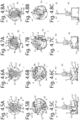
- Figs. 4.1A-4.11C show a second embodiment of the drive component 1.
- the rotation energization 12 in particular the centrifugal energization, is visualized in successive steps and further explained below.
- the second embodiment comprises the same elements as the first embodiment described above.
- the rotation limiter 5 comprises further cooperating blocking elements 7 on the first 2 and second rotation part 3, respectively, wherein the second rotation part 3 is provided with a second radially outwardly extending cam 18 which is disposed opposite to and along the central axis 4 remote from the radially outwardly extending cam 8b, and a second receiving groove 19 which is disposed opposite to and along the central axis 4 remote from the receiving groove 9b, and wherein the first rotation part 2 is provided with a further receiving groove 20 near the inwardly extending cam 9a.
- the radially inwardly extending cam 9a is arranged to cooperate in the second position II of the passer 6 with receiving groove 9b.
- the radially inwardly extending cam 9a is further arranged to cooperate in the second position II of the passer 6 with the second receiving groove 19 while the radially outwardly extending cam 8b cooperates with the further receiving groove 20.
- Figs. 4.1A-4.11C show stepwise rotation of the drive component 1, whereby the first rotation part 2 is driven.
- the second rotation part 3 rotates to illustrate the working of the second embodiment.
- first position B of Figs. 4.1A-4.1C the slide 11, in particular the passer 6, is in the first position I.
- the eccentric weights 12a are in the radially inner position R1.
- the second rotation part 3 is in a first axial position A1.
- Figs. 4.8A-4.8C the angular position ⁇ has increased until the inwardly extending cam 8a cooperates with the outwardly extending cam 18, such that the rotation limiter 5 limits rotation between the rotation parts 2, 3 to the angular position ⁇ 2.
- Fig. 4.8C it is represented that the second rotation part 3 has been displaced via the rotation-translation converter 10 with respect to the first rotation part 2 axially along the central axis 4 to the first axial position A1.
- the rotation parts 2, 3 cooperate via the rotation-translation converter 10.
- the limited rotation between successive angular positions ⁇ brings about a radial and/or axial shift of the rotation parts 2, 3 with respect to each other.
- the drive component 1 of both above-described embodiments is provided with the finger 10a, not visible, cooperating with the endless helical groove 10b, so that the rotation parts 2, 3 can move axially up and down with respect to each other along the central axis 4.
- the second rotation part 3 forms an output shaft 24. Additionally or alternatively, the second rotation part 3 may be coupled with an output shaft 24, as is for instance shown in Fig. 5 and will be further elucidated below.
- the second rotation part 3 is arranged for, during the limited rotation between successive angular positions ⁇ of the rotation parts 2, 3, giving an operating pulse by means of axial translation.
- Fig. 5 shows a further elaborated example of a drive 25 according to the invention.
- the drive 25 comprises an electric motor 26, in particular a DC electric motor.
- the drive 25 comprises a drive component 1.
- the drive component comprises a first rotation part 2 and a second rotation part 3.
- the rotation parts in this example are arranged to rotate together around a common central axis, and to rotate around that axis with respect to each other.
- the second rotation part 3 is axially adjustable with respect to the first rotation part 1 between a first position and a second position.
- the drive component 1 is implemented in this example as the above-described second embodiment of the implementation example.
- the second rotation part 3 may also be axially adjustable with respect to the first rotation part 2 between a first position and a second axial position in a different manner than by relative rotation with the above-described rotation-energized indexer, for example by means of axial displacement with the aid of electromagnetic operation.
- An output shaft 27 of the electric motor 26 is fixedly coupled with the first rotation part 2.
- the second rotation part 3 is axially adjustable with respect to the first rotation part 2.
- the second rotation part 3 of the drive component 1 further cooperates via a rotation-translation converter 40 in an axially telescoping manner with an output shaft 24 of the drive component 1.
- the second rotation part 3 and the output shaft 24 together form an axially telescoping driving shaft.
- the cylindrical output shaft 24 of the drive component 1, in this example, is received with a sliding fit in a hollow cylindrical shaft portion of the second rotation part 3, and one of the two members is provided with one or more pins which are received in one or more corresponding helical grooves in the other member.
- a screw thread operative between the two members may be opted for.
- the output shaft 24 of the drive component in turn cooperates with a further component 28 of the drive 25, in particular via a gear 32 carried on the output shaft 24.
- the gear 32 is axially adjustable between a slid-in drive shaft position corresponding to a first direction of rotation M+ of the motor 26 (shown in Fig. 5 , and resulting from driving to the right), and a slid-out drive shaft position corresponding to the opposite direction of rotation M- of the motor 26 (not represented in Fig. 5 , and resulting from driving to the left).
- the further component 28 of the drive 25 is a transmission 29 in this exemplary embodiment.
- the output shaft 24 cooperates with the transmission 29.
- the output shaft 24, upon successive energization of the motor 26 in the same direction, so to the right here, is then switchable, through axial adjustment of the second rotation part 3 with respect to the first rotation part 2, between the first driving path 30 and the second driving path 31 of the first output branch 42 of the transmission 29.
- the output shaft 24 has, in the first angular position ⁇ 1 of the second rotation part 3 with respect to the first rotation part 2, a first axial position A1 in which the output shaft 24 drives the first driving path 30 of the transmission 29. In the further angular position ⁇ 2, the output shaft 24 has the second axial position A2 in which it drives the second driving path 31 of the transmission 29 (not shown). In these two axial positions A1 and A2, the axially telescoping rotation-translation converter 40 is always in the slid-in drive shaft position.
- the output shaft 24 comprises a gear 32 which in the first driving path 30 cooperates with an input gear 33 which is included in the first output branch 42 of the transmission 29 to rotate a first output element 41 of the transmission 29, here a first worm gear, in a first direction of rotation P1+.
- the gear 32 cooperates with input gear 34 which is included in the transmission 29 to rotate the first output element 41 of the transmission 29 via intermediate gear pair 35 in an opposite direction of rotation P1-.
- the third driving path 44 and the fourth driving path 48 are located in the second output branch 45 of the transmission 29.
- the output shaft 24 has, in the first angular position ⁇ 1 of the second rotation part 3 with respect to the first rotation part 2, a first axial position B1 in which the output shaft 24 drives the third driving path 44 of the transmission 29 (not represented). In the further angular position ⁇ 2 the output shaft 24 has the second axial position B2 in which it drives the fourth driving path 48 of the transmission 29 (not represented).
- the drive shaft with the axially telescoping rotation-translation converter 40 is always in the slid-out drive shaft position.
- the gear 32 of the output shaft 24 cooperates in the third driving path 44 with the input gear 46 to rotate a second output element 49 of the transmission 29, here a second worm gear, positively in a second direction of rotation P2+.
- the gear 32 cooperates with an input gear 47 which is included in the second output branch 45 of the transmission 29 to rotate the second output element 49 of the transmission 29 via intermediate gear pair 50 negatively in the second direction of rotation P2-. It is noted that upon adjustment between the two axial shaft positions B1 and B2, the gear 32 moves along input gear 34 of the second driving path 31 of first output branch 42, though without remaining in engagement therewith to drive the gear 34.
- each of the output elements 41, 49 implemented as worm gear for example a final stage of an actuator can be driven, for example a final stage 51, represented for the second output branch 45, for pivoting an exterior vision unit for a motor vehicle, such as a camera or exterior mirror, about an adjustment axis.
- an exterior vision unit can be pivoted about two adjustment axes, for example x and y, and, by successive energization of the motor in the same direction M+ and M+ or M- and M-, be pivoted alternately in positive or negative direction about that adjustment axis x or y.
- a telescoping rotation-translation converter can also in itself be seen as an additional function, and can be configured in many embodiments which are however not a part of the present invention.
- the invention may for instance be used in an adjustable head rest, a trunk lid, a fuel tank/charging socket flap unit, a sunroof, headlight adjustment, and/or a side door of a vehicle.
- the invention is for instance eminently suitable to be used in inter alia window furnishings, a (security) camera or a drilling machine.
- an adjusting module for operating a flap can comprise a drive component which is provided with features such as described above, whereby an output adjusting element of the adjusting module is coupled with the first rotation part of the drive component for adjustment of the flap between at least an open position and a covering position, and wherein the first and/or the second rotation part of the drive component cooperates via a transmission with a lock of the flap for adjusting the lock between at least a locked position and an unlocked position.
- both the opening and closing of the flap and the lock of the flap can be relatively simply operated.
- a drive comprising an electric motor, in particular a DC electric motor
- a tailboard or loading flap of a vehicle can be pivoted with the adjusting module about a pivoting axis and/or be translated along a guide, in particular a guide rail provision.
- the same drive can lock and/or unlock the lock of the loading flap.
- a flap part of a fuel tank/charging-socket flap unit of a vehicle can be adjusted with the adjusting module between the open and/or covering, shut position, and lock a lock, in particular one implemented as a pin, of the fuel tank/charging-socket flap unit, or a charging cable, in particular a plug of the charging cable, when the charging cable during recharging is connected to the vehicle.
- a lock in particular one implemented as a pin
- a charging cable in particular a plug of the charging cable
- a drive may be provided with a drive component with features as described above, whereby upon a first energization an output shaft of the drive is coupled with the first rotation part of the drive component so that the first rotation part via a transmission traverses a first adjustment stage whereby adjustment can be done with a relatively high speed and relatively low couple, and whereby upon a second successive energization the output shaft of the drive is coupled with the first and/or the second rotation part of the drive component so that the first and/or the second rotation part traverses a second adjustment stage via a further transmission whereby adjustment can be done with a low speed and relatively high couple.
- closing and thereupon locking a trunk lid, a fuel tank/charging-socket flap unit, sunroof and/or side door of a motor vehicle can be facilitated.
- Such an adjusting module provided with a drive component with features as described above, optionally provided with a drive, may for instance also be used for adjusting and/or locking e.g. side doors, hood and/or sunroof of a vehicle.
- couple-producing power sources that can generate a couple only in one direction by the nature of their functioning, such as, for example, watermills, wind turbines, particular types of AC motors and piezo motors.
- An application could be to provide such power sources with a drive component with features such as described above so that upon successive energization, for example, a direction of rotation of an output shaft is changed via a transmission.
- a drive component may be applied in a cost-saving manner in e.g. sustainable energy sources such as solar cell fields, or in agriculture for irrigation, in particular by virtue of a simplified construction for which fewer drives are needed for adjustment between two, three, four or more positions and/or a plurality of components.
- Such an adjusting module provided with a drive component with features as described hereinabove, optionally provided with a drive, may also be used, for instance, for adjusting and/or locking side doors, hood and/or sunroof of a vehicle.
- an adjusting module for a window furnishing having at least one slat in particular blinds, such as luxaflex ® or Venetian blinds
- a drive component which is provided with features as described hereinabove, whereby an output shaft of the adjusting module is coupled with the first rotation part for rotating adjustment of the at least one slat about its longitudinal axis, and whereby the first and/or the second rotation part of the drive component cooperates with an output element of the adjusting module for translating adjustment of the at least one slat substantially transverse to its longitudinal axis along a guide of the adjusting module.
- the at least one slat By coupling an output shaft of the adjusting module with the first rotation part of the drive component for adjustment of the at least one slat about its longitudinal axis, the at least one slat can be adjusted between at least a blinding condition and a release condition, such that e.g. the amount of transmitted light can be controlled.
- the first and/or the second rotation part of the drive component cooperate(s) with an output element of the adjusting module for adjustment of the at least one slat substantially transverse to its longitudinal axis along a guide of the adjusting module, it can be achieved that the at least one slat is adjusted e.g.
- the guide may for instance be implemented as a guide rail or as cords.
- the adjusting module may for instance be operated manually and/or with an electric drive.
- Such an adjusting module provided with a drive component with features as described hereinabove may for instance also be used in (security) cameras for pivoting the security camera via a transmission of the adjusting module, about at least a lying axis and/or a standing axis, or in a (head) rest for adjusting the (head) rest in angular position and/or height.
- the adjusting module provided with the drive component may also be used to adjust more positions than two, e.g. three, four or more, such as infinitely many positions.
Landscapes
- Engineering & Computer Science (AREA)
- Multimedia (AREA)
- Mechanical Engineering (AREA)
- Transmission Devices (AREA)
- Rear-View Mirror Devices That Are Mounted On The Exterior Of The Vehicle (AREA)
- Machine Tool Positioning Apparatuses (AREA)
Claims (17)
- Antriebskomponente (1) umfassend ein erstes Rotationsteil (2) und ein zweites Rotationsteil (3), die angeordnet sind, um zusammen um eine gemeinsame Mittelachse (4) zu rotieren und um diese Mittelachse (4) in Bezug zueinander zu rotieren, ferner umfassend einen Rotationsbegrenzer (5), der zwischen den beiden Rotationsteilen (2, 3) wirkt, der die Rotation zwischen den Rotationsteilen (2, 3) begrenzt, wobei der Rotationsbegrenzer (5) so angeordnet ist, dass, wenn das erste Rotationsteil (2) zur Rotation angetrieben wird, das erste Rotationsteil (2) nach Durchlaufen eines freien Winkelhubs das zweite Rotationsteil (3) in einer durch den Rotationsbegrenzer (5) bestimmten gegenseitigen Winkelposition, d. h. der Mitnahmewinkel, entlang der Rotation mitnimmt, wobei der Rotationsbegrenzer (5) einen Indexer (36) umfasst, der durch die Rotation des ersten und/oder zweiten Rotationsteils (2, 3) erregt wird, so dass in aufeinanderfolgenden Antriebszyklen an der Antriebskomponente (1), wobei in jedem Antriebszyklus das erste Rotationsteil (2) aus der Ruhe in die Rotation versetzt wird und das zweite Rotationsteil (3) nach der Mitnahme wieder zur Ruhe gekommen ist, der Mitnahmewinkel indexiert wird und sich die Rotationsteile (2, 3) in aufeinanderfolgenden Antriebszyklen in der gegenseitigen Winkelposition bei der Mitnahme unterscheiden.
- Antriebskomponente (1) nach Anspruch 1, wobei der Indexer (36) einen Umlenker (6) umfasst, der angeordnet ist, um mindestens eines der Rotationsteile (2, 3) den Rotationsbegrenzer (5) passieren zu lassen.
- Antriebskomponente (1) nach Anspruch 1 oder 2, wobei der Rotationsbegrenzer (5) zusammenwirkende Sperrelemente (7) am ersten bzw. zweiten Rotationsteil (3) umfasst.
- Antriebskomponente (1) nach Anspruch 3, wobei die Sperrelemente (7) ein zusammenwirkendes Nockenpaar (8) umfassen.
- Antriebskomponente (1) nach Anspruch 3 oder 4, wobei die Sperrelemente (7) ein zusammenwirkendes Nocken- und Nutenpaar (9) umfassen.
- Antriebskomponente (1) nach einem der Ansprüche 2 bis 5, wobei der Umlenker (6) angeordnet ist, um zusammenwirkende Sperrelemente (7) des Rotationsbegrenzers (5) radial und/oder axial zueinander zu verstellen, damit die Rotationsteile (2, 3) passieren können.
- Antriebskomponente (1) nach einem der vorstehenden Ansprüche, wobei der Umlenker (6) einen Rotations-Translations-Wandler (10) umfasst.
- Antriebskomponente (1) nach einem der vorstehenden Ansprüche, wobei der Umlenker (6) einen quer zur Mittelachse (4) verlaufenden Schieber (11) aufweist.
- Antriebskomponente (1) nach einem der vorstehenden Ansprüche, wobei der Umlenker (6) eine Rotationserregung (12) umfasst, die den Umlenker (6) bei Rotation eines der Rotationsteile (2, 3), vorzugsweise bei Rotation des ersten Rotationsteils (2), erregt.
- Antriebskomponente (1) nach Anspruch 9, wobei die Rotationserregung (12) eine Zentrifugalerregung (12) umfasst.
- Antriebskomponente (1) nach einem der vorstehenden Ansprüche, wobei der Umlenker (6) gefedert ist.
- Antriebskomponente (1) nach einem der vorstehenden Ansprüche, wobei mindestens eines der Rotationsteile (2, 3) angeordnet ist, um während der begrenzten Rotation zwischen aufeinanderfolgenden Winkelpositionen der Rotationsteile (2, 3) einen Betriebsimpuls abzugeben.
- Antriebskomponente (1) nach einem der vorstehenden Ansprüche, wobei die Rotationsteile (2, 3) über einen Rotations-Translations-Wandler (10) zusammenwirken und wobei die begrenzte Rotation zwischen aufeinanderfolgenden Winkelpositionen eine axiale Verschiebung der Rotationsteile (2, 3) zueinander bewirkt.
- Antriebskomponente (1) nach einem der vorstehenden Ansprüche, wobei das zweite Rotationsteil (3) eine Abtriebswelle bildet oder mit einer Abtriebswelle gekoppelt ist und wobei mindestens eines der Rotationsteile (2, 3) angeordnet ist, um während der begrenzten Rotation zwischen aufeinanderfolgenden Winkelpositionen der Rotationsteile (2, 3) einen Betriebsimpuls durch axiale Translation abzugeben.
- Antrieb (25), umfassend einen Elektromotor (26), insbesondere einen Gleichstrom-Elektromotor (26), und eine Antriebskomponente (1) nach einem der vorstehenden Ansprüche, wobei eine Abtriebswelle (27) des Elektromotors (26) mit dem ersten Rotationsteil (2) gekoppelt ist, und wobei das erste und/oder zweite Rotationsteil (2, 3) der Antriebskomponente (1) mit einer weiteren Komponente (28) eines Antriebs (25) zusammenwirkt.
- Antrieb (25) nach Anspruch 15, soweit von Anspruch 14 abhängig, wobei die weitere Komponente (28) des Antriebs (25) ein Getriebe (29) ist, und wobei die Abtriebswelle (27) mit dem Getriebe (29) zusammenwirkt, und wobei die Abtriebswelle (27) in der ersten Winkelposition (al) eine erste axiale Position (A1) hat, in der sie einen ersten Übertragungsweg (30) des Getriebes (29) antreibt, und in der weiteren Winkelposition (a2) eine zweite axiale Position (A2) hat, in der sie einen zweiten Übertragungsweg (31) des Getriebes (29) antreibt.
- Verfahren zum Antreiben eines Verstellinstruments, umfassend einen Antrieb (25) nach einem der Ansprüche 15 oder 16, wobei durch Erregung eines Elektromotors (26) ein erstes Rotationsteil (2) und ein zweites Rotationsteil (3) einer Antriebskomponente (1) durch eine in aufeinanderfolgenden Winkelpositionen begrenzte Rotation zwischen dem ersten und dem zweiten Rotationsteil (2, 3) in einer gegenseitigen Winkelposition zueinander indexiert werden.
Priority Applications (1)
| Application Number | Priority Date | Filing Date | Title |
|---|---|---|---|
| EP24195464.3A EP4442511A3 (de) | 2019-09-23 | 2020-09-23 | Antriebskomponente für ein verstellinstrument |
Applications Claiming Priority (2)
| Application Number | Priority Date | Filing Date | Title |
|---|---|---|---|
| NL2023881A NL2023881B1 (nl) | 2019-09-23 | 2019-09-23 | Aandrijvingscomponent voor een verstelinstrument |
| PCT/NL2020/050586 WO2021060979A1 (en) | 2019-09-23 | 2020-09-23 | Driving component for an adjusting instrument |
Related Child Applications (2)
| Application Number | Title | Priority Date | Filing Date |
|---|---|---|---|
| EP24195464.3A Division EP4442511A3 (de) | 2019-09-23 | 2020-09-23 | Antriebskomponente für ein verstellinstrument |
| EP24195464.3A Division-Into EP4442511A3 (de) | 2019-09-23 | 2020-09-23 | Antriebskomponente für ein verstellinstrument |
Publications (2)
| Publication Number | Publication Date |
|---|---|
| EP4034423A1 EP4034423A1 (de) | 2022-08-03 |
| EP4034423B1 true EP4034423B1 (de) | 2024-10-09 |
Family
ID=69375932
Family Applications (2)
| Application Number | Title | Priority Date | Filing Date |
|---|---|---|---|
| EP24195464.3A Pending EP4442511A3 (de) | 2019-09-23 | 2020-09-23 | Antriebskomponente für ein verstellinstrument |
| EP20780374.3A Active EP4034423B1 (de) | 2019-09-23 | 2020-09-23 | Antriebskomponente für ein verstellinstrument |
Family Applications Before (1)
| Application Number | Title | Priority Date | Filing Date |
|---|---|---|---|
| EP24195464.3A Pending EP4442511A3 (de) | 2019-09-23 | 2020-09-23 | Antriebskomponente für ein verstellinstrument |
Country Status (7)
| Country | Link |
|---|---|
| US (1) | US12447898B2 (de) |
| EP (2) | EP4442511A3 (de) |
| JP (1) | JP7700103B2 (de) |
| KR (1) | KR102754751B1 (de) |
| CN (1) | CN114667238A (de) |
| NL (1) | NL2023881B1 (de) |
| WO (1) | WO2021060979A1 (de) |
Family Cites Families (20)
| Publication number | Priority date | Publication date | Assignee | Title |
|---|---|---|---|---|
| NL1003144C2 (nl) * | 1996-05-15 | 1997-11-18 | Iku Holding Montfoort Bv | Elektrisch bedienbare scharnieractuator, en buitenspiegel met elektrisch bedienbaar scharniermechanisme. |
| DE19833514B4 (de) * | 1997-07-30 | 2005-04-28 | Buhler Motor Gmbh | Antrieb zum Abklappen eines Kraftfahrzeugrückblickspiegels |
| NL1007139C2 (nl) | 1997-09-26 | 1999-03-29 | Iku Holding Montfoort Bv | Actuator. |
| DE10009670B4 (de) * | 2000-02-29 | 2005-08-04 | Bühler Motor GmbH | Außenrückblickspiegel für ein Kraftfahrzeug |
| NL1018687C2 (nl) * | 2001-08-02 | 2003-02-04 | Iku Holding Montfoort Bv | Scharnierconstructie en scharnieractuator, in het bijzonder voor een buitenspiegel van een motorvoertuig. |
| CN1659063A (zh) | 2002-04-09 | 2005-08-24 | 麦格纳唐纳尼车镜北美有限责任公司 | 利用单马达促动的车镜促动器 |
| WO2005075249A1 (en) * | 2004-02-06 | 2005-08-18 | Eaton Automotive B.V. | Hinge actuator and method for adjusting two parts of a hinge actuator relative to each other |
| NL1025437C2 (nl) * | 2004-02-06 | 2005-08-09 | Iku Holding Montfoort Bv | Scharnieractuator. |
| NL1026002C2 (nl) * | 2004-04-22 | 2005-10-25 | Iku Holding Montfoort Bv | Scharnieractuator, in het bijzonder voor een buitenspiegeleenheid. |
| NL2006301C2 (nl) * | 2010-10-06 | 2012-04-11 | Mci Mirror Controls Int Nl Bv | Verstelmechanisme. |
| JP2013075618A (ja) | 2011-09-30 | 2013-04-25 | Ichikoh Ind Ltd | 車両用アウトサイドミラー装置 |
| NL2013771B1 (nl) | 2014-11-11 | 2016-10-06 | MCI (Mirror Controls International) Netherlands B V | Inrichting voor het verstellen van een schaalvormig behuizingsdeel, een draagframe voor gebruik in een dergelijke inrichting, en een voertuig voorzien van een dergelijke inrichting. |
| CN105034957B9 (zh) * | 2015-08-22 | 2023-11-17 | 宁波精成车业有限公司 | 用于汽车外后视镜的电动折叠装置 |
| CN204821345U (zh) | 2015-08-22 | 2015-12-02 | 宁波精成车业有限公司 | 用于汽车外后视镜的电动折叠装置 |
| NL2015676B1 (nl) * | 2015-10-28 | 2017-05-29 | MCI (Mirror Controls International) Netherlands B V | Verstelinstrument voor een buitenzichteenheid voor een voertuig. |
| NL2015897B1 (nl) * | 2015-12-02 | 2017-06-28 | MCI (Mirror Controls International) Netherlands B V | Bevestigingsconstructie, in het bijzonder voor een buitenzichteenheid van een motorvoertuig. |
| NL2019778B1 (nl) * | 2017-10-20 | 2019-04-29 | Mci Mirror Controls Int Netherlands B V | Bevestigingsconstructie, in het bijzonder voor een buitenzichteenheid van een motorvoertuig |
| NL2020641B1 (nl) * | 2018-03-21 | 2019-10-02 | Mci Mirror Controls Int Netherlands B V | Aandrijving voor een verstelinstrument, in het bijzonder voor het verstellen van een buitenzichteenheid van een motorvoertuig |
| DE102019122105B3 (de) * | 2019-08-16 | 2020-11-05 | Motherson Innovations Company Limited | Kombinierter Aktuator zum Klappen und Anheben von Spiegeln, Rückblickeinrichtung und Fahrzeug |
| US10940801B1 (en) * | 2019-09-09 | 2021-03-09 | Motherson Innovations Company Limited | Actuating device for a component |
-
2019
- 2019-09-23 NL NL2023881A patent/NL2023881B1/nl active
-
2020
- 2020-09-23 EP EP24195464.3A patent/EP4442511A3/de active Pending
- 2020-09-23 EP EP20780374.3A patent/EP4034423B1/de active Active
- 2020-09-23 US US17/762,633 patent/US12447898B2/en active Active
- 2020-09-23 WO PCT/NL2020/050586 patent/WO2021060979A1/en not_active Ceased
- 2020-09-23 KR KR1020227012000A patent/KR102754751B1/ko active Active
- 2020-09-23 JP JP2022517989A patent/JP7700103B2/ja active Active
- 2020-09-23 CN CN202080076430.5A patent/CN114667238A/zh active Pending
Also Published As
| Publication number | Publication date |
|---|---|
| CN114667238A (zh) | 2022-06-24 |
| US12447898B2 (en) | 2025-10-21 |
| JP7700103B2 (ja) | 2025-06-30 |
| EP4442511A3 (de) | 2024-12-18 |
| NL2023881B1 (nl) | 2021-05-25 |
| EP4034423A1 (de) | 2022-08-03 |
| KR102754751B1 (ko) | 2025-01-14 |
| US20220348140A1 (en) | 2022-11-03 |
| WO2021060979A1 (en) | 2021-04-01 |
| EP4442511A2 (de) | 2024-10-09 |
| JP2022548388A (ja) | 2022-11-18 |
| KR20220098722A (ko) | 2022-07-12 |
Similar Documents
| Publication | Publication Date | Title |
|---|---|---|
| US12024093B2 (en) | Combined actuator for mirror folding and lifting, rear view device and vehicle | |
| CN111315953B (zh) | 用于机动车技术方面的应用的调节驱动装置 | |
| EP3768556B1 (de) | Antrieb für ein verstellinstrument, insbesondere zur verstellung einer aussensichteinheit eines kraftfahrzeugs | |
| CN101524958A (zh) | 用于车辆的至少两个活动零件的驱动单元,特别是其车顶组件 | |
| CN115003930A (zh) | 用于机动车技术设备的调节驱动装置 | |
| US10759515B2 (en) | Electromechanical hinge-line rotary actuator | |
| EP4034423B1 (de) | Antriebskomponente für ein verstellinstrument | |
| CN107542336A (zh) | 杆式锁 | |
| CN114313250A (zh) | 折叠装置、螺旋桨、旋翼模组及飞行设备 | |
| WO2021069981A1 (en) | Rotary mechanical screw transmission | |
| CA2702967C (en) | Drive for transit door | |
| EP4155490B1 (de) | Innengriff für ein kraftfahrzeug und dessen verwendung | |
| EP1213419B1 (de) | Stellantrieb | |
| JP7832957B2 (ja) | 自動車用途の為の電動駆動装置 | |
| CN108995595A (zh) | 用于折叠式后视镜组件的致动器机构 | |
| US11958598B2 (en) | Wing for an aircraft | |
| CN110259292A (zh) | 汽车滑门锁用自吸驱动机构 | |
| US7540207B2 (en) | Device for actuating the doors of vehicles | |
| JP7764493B2 (ja) | 自動車用途の為の電動駆動装置 | |
| KR20100043776A (ko) | 차량의 선 쉐이드 구동장치 | |
| KR20090080852A (ko) | 차량용 전동식 썬 쉐이드 | |
| CN218577626U (zh) | 一种手套箱 | |
| CN120024177B (zh) | 一种用于出风口的单电机驱动机构及出风口组件 | |
| CN120828737A (zh) | 同步打开机构、对开扶手箱、副仪表总成和车辆 | |
| KR20010027164A (ko) | 모터를 이용한 다기능 작동구조 |
Legal Events
| Date | Code | Title | Description |
|---|---|---|---|
| STAA | Information on the status of an ep patent application or granted ep patent |
Free format text: STATUS: UNKNOWN |
|
| STAA | Information on the status of an ep patent application or granted ep patent |
Free format text: STATUS: THE INTERNATIONAL PUBLICATION HAS BEEN MADE |
|
| PUAI | Public reference made under article 153(3) epc to a published international application that has entered the european phase |
Free format text: ORIGINAL CODE: 0009012 |
|
| STAA | Information on the status of an ep patent application or granted ep patent |
Free format text: STATUS: REQUEST FOR EXAMINATION WAS MADE |
|
| 17P | Request for examination filed |
Effective date: 20220413 |
|
| AK | Designated contracting states |
Kind code of ref document: A1 Designated state(s): AL AT BE BG CH CY CZ DE DK EE ES FI FR GB GR HR HU IE IS IT LI LT LU LV MC MK MT NL NO PL PT RO RS SE SI SK SM TR |
|
| DAV | Request for validation of the european patent (deleted) | ||
| DAX | Request for extension of the european patent (deleted) | ||
| P01 | Opt-out of the competence of the unified patent court (upc) registered |
Effective date: 20230516 |
|
| GRAP | Despatch of communication of intention to grant a patent |
Free format text: ORIGINAL CODE: EPIDOSNIGR1 |
|
| STAA | Information on the status of an ep patent application or granted ep patent |
Free format text: STATUS: GRANT OF PATENT IS INTENDED |
|
| INTG | Intention to grant announced |
Effective date: 20240426 |
|
| GRAS | Grant fee paid |
Free format text: ORIGINAL CODE: EPIDOSNIGR3 |
|
| GRAA | (expected) grant |
Free format text: ORIGINAL CODE: 0009210 |
|
| STAA | Information on the status of an ep patent application or granted ep patent |
Free format text: STATUS: THE PATENT HAS BEEN GRANTED |
|
| AK | Designated contracting states |
Kind code of ref document: B1 Designated state(s): AL AT BE BG CH CY CZ DE DK EE ES FI FR GB GR HR HU IE IS IT LI LT LU LV MC MK MT NL NO PL PT RO RS SE SI SK SM TR |
|
| REG | Reference to a national code |
Ref country code: CH Ref legal event code: EP |
|
| REG | Reference to a national code |
Ref country code: DE Ref legal event code: R096 Ref document number: 602020039178 Country of ref document: DE |
|
| REG | Reference to a national code |
Ref country code: IE Ref legal event code: FG4D |
|
| REG | Reference to a national code |
Ref country code: LT Ref legal event code: MG9D |
|
| REG | Reference to a national code |
Ref country code: NL Ref legal event code: MP Effective date: 20241009 |
|
| REG | Reference to a national code |
Ref country code: AT Ref legal event code: MK05 Ref document number: 1730266 Country of ref document: AT Kind code of ref document: T Effective date: 20241009 |
|
| PG25 | Lapsed in a contracting state [announced via postgrant information from national office to epo] |
Ref country code: NL Free format text: LAPSE BECAUSE OF FAILURE TO SUBMIT A TRANSLATION OF THE DESCRIPTION OR TO PAY THE FEE WITHIN THE PRESCRIBED TIME-LIMIT Effective date: 20241009 |
|
| PG25 | Lapsed in a contracting state [announced via postgrant information from national office to epo] |
Ref country code: NL Free format text: LAPSE BECAUSE OF FAILURE TO SUBMIT A TRANSLATION OF THE DESCRIPTION OR TO PAY THE FEE WITHIN THE PRESCRIBED TIME-LIMIT Effective date: 20241009 |
|
| PG25 | Lapsed in a contracting state [announced via postgrant information from national office to epo] |
Ref country code: PT Free format text: LAPSE BECAUSE OF FAILURE TO SUBMIT A TRANSLATION OF THE DESCRIPTION OR TO PAY THE FEE WITHIN THE PRESCRIBED TIME-LIMIT Effective date: 20250210 Ref country code: HR Free format text: LAPSE BECAUSE OF FAILURE TO SUBMIT A TRANSLATION OF THE DESCRIPTION OR TO PAY THE FEE WITHIN THE PRESCRIBED TIME-LIMIT Effective date: 20241009 Ref country code: IS Free format text: LAPSE BECAUSE OF FAILURE TO SUBMIT A TRANSLATION OF THE DESCRIPTION OR TO PAY THE FEE WITHIN THE PRESCRIBED TIME-LIMIT Effective date: 20250209 |
|
| PG25 | Lapsed in a contracting state [announced via postgrant information from national office to epo] |
Ref country code: FI Free format text: LAPSE BECAUSE OF FAILURE TO SUBMIT A TRANSLATION OF THE DESCRIPTION OR TO PAY THE FEE WITHIN THE PRESCRIBED TIME-LIMIT Effective date: 20241009 |
|
| PG25 | Lapsed in a contracting state [announced via postgrant information from national office to epo] |
Ref country code: BG Free format text: LAPSE BECAUSE OF FAILURE TO SUBMIT A TRANSLATION OF THE DESCRIPTION OR TO PAY THE FEE WITHIN THE PRESCRIBED TIME-LIMIT Effective date: 20241009 |
|
| PG25 | Lapsed in a contracting state [announced via postgrant information from national office to epo] |
Ref country code: ES Free format text: LAPSE BECAUSE OF FAILURE TO SUBMIT A TRANSLATION OF THE DESCRIPTION OR TO PAY THE FEE WITHIN THE PRESCRIBED TIME-LIMIT Effective date: 20241009 |
|
| PG25 | Lapsed in a contracting state [announced via postgrant information from national office to epo] |
Ref country code: NO Free format text: LAPSE BECAUSE OF FAILURE TO SUBMIT A TRANSLATION OF THE DESCRIPTION OR TO PAY THE FEE WITHIN THE PRESCRIBED TIME-LIMIT Effective date: 20250109 |
|
| PG25 | Lapsed in a contracting state [announced via postgrant information from national office to epo] |
Ref country code: LV Free format text: LAPSE BECAUSE OF FAILURE TO SUBMIT A TRANSLATION OF THE DESCRIPTION OR TO PAY THE FEE WITHIN THE PRESCRIBED TIME-LIMIT Effective date: 20241009 Ref country code: GR Free format text: LAPSE BECAUSE OF FAILURE TO SUBMIT A TRANSLATION OF THE DESCRIPTION OR TO PAY THE FEE WITHIN THE PRESCRIBED TIME-LIMIT Effective date: 20250110 Ref country code: AT Free format text: LAPSE BECAUSE OF FAILURE TO SUBMIT A TRANSLATION OF THE DESCRIPTION OR TO PAY THE FEE WITHIN THE PRESCRIBED TIME-LIMIT Effective date: 20241009 |
|
| PG25 | Lapsed in a contracting state [announced via postgrant information from national office to epo] |
Ref country code: PL Free format text: LAPSE BECAUSE OF FAILURE TO SUBMIT A TRANSLATION OF THE DESCRIPTION OR TO PAY THE FEE WITHIN THE PRESCRIBED TIME-LIMIT Effective date: 20241009 |
|
| PG25 | Lapsed in a contracting state [announced via postgrant information from national office to epo] |
Ref country code: RS Free format text: LAPSE BECAUSE OF FAILURE TO SUBMIT A TRANSLATION OF THE DESCRIPTION OR TO PAY THE FEE WITHIN THE PRESCRIBED TIME-LIMIT Effective date: 20250109 |
|
| PG25 | Lapsed in a contracting state [announced via postgrant information from national office to epo] |
Ref country code: SM Free format text: LAPSE BECAUSE OF FAILURE TO SUBMIT A TRANSLATION OF THE DESCRIPTION OR TO PAY THE FEE WITHIN THE PRESCRIBED TIME-LIMIT Effective date: 20241009 |
|
| PG25 | Lapsed in a contracting state [announced via postgrant information from national office to epo] |
Ref country code: DK Free format text: LAPSE BECAUSE OF FAILURE TO SUBMIT A TRANSLATION OF THE DESCRIPTION OR TO PAY THE FEE WITHIN THE PRESCRIBED TIME-LIMIT Effective date: 20241009 |
|
| REG | Reference to a national code |
Ref country code: DE Ref legal event code: R097 Ref document number: 602020039178 Country of ref document: DE |
|
| PG25 | Lapsed in a contracting state [announced via postgrant information from national office to epo] |
Ref country code: EE Free format text: LAPSE BECAUSE OF FAILURE TO SUBMIT A TRANSLATION OF THE DESCRIPTION OR TO PAY THE FEE WITHIN THE PRESCRIBED TIME-LIMIT Effective date: 20241009 |
|
| PG25 | Lapsed in a contracting state [announced via postgrant information from national office to epo] |
Ref country code: RO Free format text: LAPSE BECAUSE OF FAILURE TO SUBMIT A TRANSLATION OF THE DESCRIPTION OR TO PAY THE FEE WITHIN THE PRESCRIBED TIME-LIMIT Effective date: 20241009 |
|
| PG25 | Lapsed in a contracting state [announced via postgrant information from national office to epo] |
Ref country code: SK Free format text: LAPSE BECAUSE OF FAILURE TO SUBMIT A TRANSLATION OF THE DESCRIPTION OR TO PAY THE FEE WITHIN THE PRESCRIBED TIME-LIMIT Effective date: 20241009 |
|
| PG25 | Lapsed in a contracting state [announced via postgrant information from national office to epo] |
Ref country code: CZ Free format text: LAPSE BECAUSE OF FAILURE TO SUBMIT A TRANSLATION OF THE DESCRIPTION OR TO PAY THE FEE WITHIN THE PRESCRIBED TIME-LIMIT Effective date: 20241009 |
|
| PG25 | Lapsed in a contracting state [announced via postgrant information from national office to epo] |
Ref country code: IT Free format text: LAPSE BECAUSE OF FAILURE TO SUBMIT A TRANSLATION OF THE DESCRIPTION OR TO PAY THE FEE WITHIN THE PRESCRIBED TIME-LIMIT Effective date: 20241009 |
|
| PLBE | No opposition filed within time limit |
Free format text: ORIGINAL CODE: 0009261 |
|
| STAA | Information on the status of an ep patent application or granted ep patent |
Free format text: STATUS: NO OPPOSITION FILED WITHIN TIME LIMIT |
|
| PG25 | Lapsed in a contracting state [announced via postgrant information from national office to epo] |
Ref country code: SE Free format text: LAPSE BECAUSE OF FAILURE TO SUBMIT A TRANSLATION OF THE DESCRIPTION OR TO PAY THE FEE WITHIN THE PRESCRIBED TIME-LIMIT Effective date: 20241009 |
|
| 26N | No opposition filed |
Effective date: 20250710 |
|
| PGFP | Annual fee paid to national office [announced via postgrant information from national office to epo] |
Ref country code: DE Payment date: 20250919 Year of fee payment: 6 |
|
| PGFP | Annual fee paid to national office [announced via postgrant information from national office to epo] |
Ref country code: GB Payment date: 20250919 Year of fee payment: 6 |
|
| PGFP | Annual fee paid to national office [announced via postgrant information from national office to epo] |
Ref country code: FR Payment date: 20250922 Year of fee payment: 6 |