EP4155490B1 - Innengriff für ein kraftfahrzeug und dessen verwendung - Google Patents
Innengriff für ein kraftfahrzeug und dessen verwendung Download PDFInfo
- Publication number
- EP4155490B1 EP4155490B1 EP22187331.8A EP22187331A EP4155490B1 EP 4155490 B1 EP4155490 B1 EP 4155490B1 EP 22187331 A EP22187331 A EP 22187331A EP 4155490 B1 EP4155490 B1 EP 4155490B1
- Authority
- EP
- European Patent Office
- Prior art keywords
- handle
- driving component
- switch
- automobile
- base
- Prior art date
- Legal status (The legal status is an assumption and is not a legal conclusion. Google has not performed a legal analysis and makes no representation as to the accuracy of the status listed.)
- Active
Links
Images

Classifications
-
- E—FIXED CONSTRUCTIONS
- E05—LOCKS; KEYS; WINDOW OR DOOR FITTINGS; SAFES
- E05B—LOCKS; ACCESSORIES THEREFOR; HANDCUFFS
- E05B85/00—Details of vehicle locks not provided for in groups E05B77/00 - E05B83/00
- E05B85/10—Handles
- E05B85/12—Inner door handles
-
- E—FIXED CONSTRUCTIONS
- E05—LOCKS; KEYS; WINDOW OR DOOR FITTINGS; SAFES
- E05B—LOCKS; ACCESSORIES THEREFOR; HANDCUFFS
- E05B81/00—Power-actuated vehicle locks
- E05B81/54—Electrical circuits
- E05B81/64—Monitoring or sensing, e.g. by using switches or sensors
- E05B81/76—Detection of handle operation; Detection of a user approaching a handle; Electrical switching actions performed by door handles
Definitions
- the disclosure belongs to the technical field of automobile, and particularly relates to an inner handle for an automobile and application thereof.
- the opening and closing of the electric car door may be performed through an electric switch, or the opening and closing of the electric car door may be performed through a mechanical inner handle arranged on the door body.
- the electric switch and the mechanical inner handle are in a split setting, so there are certain requirements for a layout and setting of the electric switch and the mechanical inner handle
- Document CN 210563903U discloses an inner door handle for an automobile in accordance with the preamble of claim 1.
- the documents WO 2013189695 A1 , DE 202016106647 U1 , WO 2021075301 A1 disclose different designs of door opening mechanism.
- the invention provides an inner handle for an automobile according to the claims to solve the problem that a car door is difficult to open when an electric opening of the vehicle door is abnormal.
- the invention provides an inner handle for an automobile.
- the inner handle for automobile includes a base, a handle, a reset assembly and a driving assembly.
- the handle is rotatably connected with the base.
- the reset assembly is located between the handle and the base.
- the driving assembly is connected with the handle and includes an electronic module and a mechanical module.
- the electronic module includes a switch and a first driving component, and the first driving component is allowed to trigger the switch during a rotation of the handle.
- the mechanical module includes a second driving component and a pulling wire, and the second driving component is allowed to pull the pulling wire during the rotation of the handle.
- the first driving component comprises a protrusion and a notch
- the switch comprises a contacting point, when the handle is in a non-rotating state, the contacting point is located in the notch, and there is a gap between the first driving component and the contacting point, when the handle rotates at a certain angle, the protrusion is in contact with the contacting point of the switch to trigger the switch.
- the inner handle for the automobile further includes a pin shaft, and the handle is rotatably connected on the pin shaft.
- the reset assembly includes a torsion spring, and the torsion spring is located between the handle and the base.
- the first driving component is connected with the handle.
- the second driving component is connected with the handle.
- the invention further provides a car door applied with the inner handle for automobile.
- the car door includes a door body, a locking structure and an inner handle.
- the locking structure is arranged on the door body.
- the inner handle includes a base, a handle, a reset assembly and a driving assembly.
- the handle is rotatably connected with the base.
- the reset assembly is located between the handle and the base.
- the driving assembly is connected with the handle and includes an electronic module and a mechanical module.
- the electronic module includes a switch and a first driving component, and the first driving component is allowed to trigger the switch during a rotation of the handle.
- the mechanical module includes a second driving component and a pulling wire, and the second driving component is allowed to pull the pulling wire during the rotation of the handle.
- the car door further includes a motor. An output end of the motor is connected with the locking structure.
- one end of the pulling wire is connected with the second driving component, and the other end of the pulling wire is connected with the locking structure.
- the invention provides the inner handle for the automobile.
- the switch of an electric car door on the handle, the switch may be first touched to realize an electric opening of the car door during an opening process of the handle.
- the handle continues to be pulled and reach an unlocking state to realize a mechanical unlocking of a door locking mechanism.
- additional electric switches may be avoided, so as to improve an actual use effect of the inner handle, which effectively reduces a risk that the car door may not be opened when the electric door is opened abnormally.
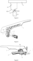
- the invention provides an inner handle for an automobile, which may be arranged on a door body to drive the door body to be opened and closed.
- a locking structure 10 is usually arranged between the door body and the vehicle body, and a connection between the vehicle body and the door body is realized through the locking structure 10. Therefore, an unlocking and locking of the locking structure 10 may be adjusted by driving the inner handle for automobiles, thereby driving an opening and closing of the door body.
- a specific structure of the locking structure 10 may not be limited, for example, the locking structure 10 may include a locking cylinder and a locking groove. A locking of the locking structure 10 is realized by clamping the locking cylinder with the locking groove, and an unlocking of the locking structure 10 is realized by separating the locking cylinder from the locking groove. And an unlocking method of the locking structure 10 is not limited, for example, the locking structure 10 may be unlocked by a mechanical module, or the locking structure 10 may be unlocked by an electronic module. An unlocking of the mechanical module means that during an unlocking process of the locking structure 10, the locking structure 10 is driven by a mechanical mechanism of the mechanical module to realize the unlocking of the locking structure 10.
- an unlocking of the electronic module means that during the unlocking process of the locking structure 10, the locking structure 10 is driven by a circuit control of the electronic module to realize the unlocking of the locking structure 10. Therefore, during an unlocking process of the electronic module, there is no input from the mechanical module.
- the inner handle for automobile may be connected with the mechanical module and the electronic module at the same time. Therefore, by driving the inner handle for automobile, the unlocking and locking of the locking structure 10 can be adjusted, thereby driving the opening and closing of the door body.
- the inner handle for automobile includes a handle 1, a base 2 and a reset assembly 3.
- the base 2 is connected with the door body, and the handle 1 is rotatably connected with the base 2.
- a pin shaft 301 may be connected with the base 2, and a through hole may be arranged on the handle 1. Therefore, the handle 1 rotates relative to the pin shaft 301 by rotatably connecting the through hole on the handle 1 with the pin shaft 301. Therefore, the handle 1 may rotate relative to the pin shaft 301 to realize a rotational connection between the handle 1 and the base 2.
- the reset assembly 3 is located between the handle 1 and the base 2, so when the handle 1 rotates relative to the base 2 by a certain angle, the reset assembly 3 is configured to reset the handle 1.
- the handle 1 may be quickly reset through the reset assembly 3.
- a specific structure of the reset assembly 3 may not be limited.
- the reset assembly 3 may include a torsion spring 302.
- the torsion spring 302 is connected between the base 2 and the handle 1, so that the handle 1 may be reset in time after rotating.
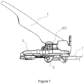
- the handle 1 is connected with the electronic module, and the electronic module includes a switch 4, a motor and a first driving component 6.
- the switch 4 is connected with a control circuit of the motor, so the motor may be driven to rotate by triggering the switch 4.
- the switch 4 may be a micro switch. Therefore, through the micro switch, a triggering precision of the switch 4 may be improved, so as to improve an actual use effect of the electronic module.
- an output end of the motor is connected with the locking cylinder, so during a rotation of the motor, the locking cylinder may be driven to be separated from the locking groove.
- a specific connection between the output end of the motor and the locking cylinder may not be limited.
- a rack may be connected to the locking cylinder, a gear is connected to the output end of the motor, and the gear and the rack are in a meshing connection. Therefore, through the rotation of the motor, the gear drives the rack to move, thereby driving the locking cylinder to move.
- the first driving component 6 is connected with the handle 1, and the first driving component 6 and the handle 1 are fixedly connected with each other, so the first driving component 6 may rotate synchronously with the handle 1. Therefore, when the first driving component 6 rotates, the switch 4 is triggered to drive the motor to rotate, thereby driving the lock cylinder to move.
- the first driving component 6 is provided with a notch 602 and a protrusion 601.
- a contacting point 5 of the switch 4 is located in the notch 602, and there is a certain gap between the first driving component 6 and the contacting point 5. Therefore, by setting the gap between the first driving component 6 and the contacting point 5, it is possible to avoid touching the micro switch by mistake, so as to improve the actual use effect of the electronic module.
- the protrusion 601 is in contact with the contacting point 5 of the switch 4 to trigger the switch 4.
- a rotation angle of the handle 1 may not be limited.
- the rotation angle of the handle 1 may be from 10 degrees to 20 degrees.
- the handle 1 is connected with the mechanical module, and the mechanical module may include a pulling wire 7 and a second driving component 8.
- the pulling wire 7 is connected with the locking cylinder, and the locking cylinder may be driven to be separated from the locking groove by pulling the pulling wire 7.
- the other end of the pulling wire 7 is connected with the second driving component 8, so the pulling wire 7 may be pulled by driving the second driving component 8.
- the second driving component 8 is connected on the handle 1 and is fixedly connected with the handle 1. During the rotation of the handle 1, the second driving component 8 may rotate synchronously with the handle 1.
- the second driving component 8 pulls the pulling wire 7, and drives the locking cylinder to be separated from the locking groove through the pulling wire7.
- the rotation angle of the handle 1 may not be limited.
- the rotation angle of the handle 1 may be at least 25 degrees.
- the first driving component 6 and the second driving component 8 may also be set as an integral structure, so as to improve a utilization rate of a space of the inner handle for automobile.
- a driving component is connected with the handle 1.
- the driving component is provided with the protrusion 601 and the notch 602, and the pulling wire 7 is also connected with the driving component. Therefore, when the door body is not opened, the contacting point 5 of the micro switch is located in the notch 602.
- the protrusion 601 triggers the contacting point 5 of the micro switch.
- the contacting point 5 of the micro switch is triggered by the protrusion 601 to turn on the motor and unlock the locking structure 10.
- the second driving component 8 pulls the pulling wire 7 and drives the locking cylinder to be separated from the locking groove through the pulling wire 7.
- the pulling wire 7 is pulled by the driving component 8 to realize an unlocking of the locking structure 10.
- the disclosure provides the inner handle for automobile, which is provided with the micro switch of the electric door on the handle.
- the micro switch In an opening process of the handle of the inner handle, first the micro switch is touched to realize an opening of the electric door. Then the handle continues to be pulled after touching the micro switch, in order to reach an unlocking state to achieve a mechanical unlocking. Therefore, by arranging an electric switch of a vehicle door in the inner handle, an additional electric switch is avoided, and the actual use effect of the inner handle is improved.
Landscapes
- Lock And Its Accessories (AREA)
Claims (8)
- Innenhandgriff für ein Kraftfahrzeug, umfassend:eine Basis (2),einen Griff (1), der drehbar mit der Basis verbunden ist,eine Rückstellvorrichtung (3), die sich zwischen dem Griff (1) und der Basis (2) befindet, undeine Antriebsvorrichtung, die mit dem Griff (1) verbunden ist und ein elektronisches Modul und ein mechanisches Modul umfasst,wobei das elektronische Modul einen Schalter (4), einen Motor und eine erste Antriebskomponente (6) umfasst, wobei der Schalter (4) mit einer Steuerschaltung des Motors verbunden ist, wobei die erste Antriebskomponente so konfiguriert ist, dass sie den Schalter (4) während einer Drehung des Griffs auslöst, undwobei das mechanische Modul eine zweite Antriebskomponente (8) und einen Zugdraht (7) umfasst, wobei die zweite Antriebskomponente (8) so konfiguriert ist, dass sie den Zugdraht (7) während der Drehung des Griffs (1) zieht,dadurch gekennzeichnet, dassdie erste Antriebskomponente (6) einen Vorsprung (601) und eine Kerbe (602) umfasst, wobei der Schalter (4) einen Kontaktpunkt (5) aufweist, wobei, wenn sich der Griff (1) in einem nicht drehenden Zustand befindet, der Kontaktpunkt (5) in der Kerbe (602) liegt und ein Spalt zwischen der ersten Antriebskomponente (6) und dem Kontaktpunkt (5) vorhanden ist,wobei, wenn sich der Griff (1) in einem bestimmten Winkel dreht, der Vorsprung (601) mit dem Kontaktpunkt (5) des Schalters (4) in Kontakt kommt, um den Schalter (4) auszulösen.
- Innenhandgriff für ein Kraftfahrzeug nach Anspruch 1, der ferner einen Stiftschaft (301) umfasst, wobei der Stiftschaft (301) mit der Basis (2) verbunden ist und der Griff (1) drehbar auf dem Stiftschaft (301) befestigt ist.
- Innenhandgriff für ein Kraftfahrzeug nach einem der vorhergehenden Ansprüche, wobei die Rückstellvorrichtung (301) eine Torsionsfeder (302) umfasst und die Torsionsfeder (302) zwischen dem Griff (1) und der Basis (2) angeordnet ist.
- Innenhandgriff für ein Kraftfahrzeug nach einem der vorhergehenden Ansprüche, wobei die erste Antriebskomponente (6) mit dem Griff (1) verbunden ist.
- Innenhandgriff für ein Kraftfahrzeug nach einem der vorhergehenden Ansprüche, wobei die zweite Antriebskomponente (8) mit dem Griff (1) verbunden ist.
- Eine Autotür, umfassend:einen Türkörper,eine Verriegelungsstruktur (10), die am Türkörper angeordnet ist, undeinen Innenhandgriff nach einem der Ansprüche 1 bis 5,wobei die Basis (2) mit dem Türkörper verbunden ist.
- Die Autotür nach Anspruch 6, die außerdem einen Motor umfasst, wobei ein Antriebsende des Motors mit der Verriegelungsstruktur (10) verbunden ist.
- Die Autotür nach Anspruch 6 oder Anspruch 7, wobei ein Ende des Zugdrahtes (7) mit der zweiten Antriebskomponente (8) verbunden ist und das andere Ende des Zugdrahtes (7) mit der Verriegelungsstruktur (10) verbunden ist.
Applications Claiming Priority (1)
| Application Number | Priority Date | Filing Date | Title |
|---|---|---|---|
| CN202122320670.XU CN218581385U (zh) | 2021-09-24 | 2021-09-24 | 一种汽车用内扣手及应用其的车门 |
Publications (3)
| Publication Number | Publication Date |
|---|---|
| EP4155490A1 EP4155490A1 (de) | 2023-03-29 |
| EP4155490B1 true EP4155490B1 (de) | 2024-08-07 |
| EP4155490C0 EP4155490C0 (de) | 2024-08-07 |
Family
ID=82748216
Family Applications (1)
| Application Number | Title | Priority Date | Filing Date |
|---|---|---|---|
| EP22187331.8A Active EP4155490B1 (de) | 2021-09-24 | 2022-07-27 | Innengriff für ein kraftfahrzeug und dessen verwendung |
Country Status (3)
| Country | Link |
|---|---|
| EP (1) | EP4155490B1 (de) |
| JP (1) | JP7389187B2 (de) |
| CN (1) | CN218581385U (de) |
Families Citing this family (2)
| Publication number | Priority date | Publication date | Assignee | Title |
|---|---|---|---|---|
| CN117846433A (zh) * | 2023-12-25 | 2024-04-09 | 雷达新能源汽车(浙江)有限公司 | 车门组件及包括其的车辆 |
| CN117868611A (zh) * | 2024-01-26 | 2024-04-12 | 上汽大众汽车有限公司 | 一种车辆的智能内开把手总成 |
Family Cites Families (7)
| Publication number | Priority date | Publication date | Assignee | Title |
|---|---|---|---|---|
| JP5293674B2 (ja) | 2010-04-22 | 2013-09-18 | アイシン精機株式会社 | 車両用ドアロック装置 |
| DE102012210278A1 (de) * | 2012-06-19 | 2013-12-19 | Bayerische Motoren Werke Aktiengesellschaft | Türinnenöffner für das Türschloss eines Kraftfahrzeuges |
| JP5781025B2 (ja) | 2012-07-09 | 2015-09-16 | 株式会社ホンダロック | 車両用ドアのラッチ解除装置 |
| DE202016106647U1 (de) * | 2016-11-29 | 2017-01-04 | Karl Heß GmbH & Co. KG Kunststoffverarbeitung | Betätigungsvorrichtung |
| CN210563903U (zh) * | 2019-05-24 | 2020-05-19 | 宁波华德汽车零部件有限公司 | 一种汽车内把手的电子机械双解锁结构 |
| US12276142B2 (en) * | 2019-10-16 | 2025-04-15 | U-Shin Ltd. | Door opening/closing detection apparatus and door opening/closing apparatus |
| CN115210439B (zh) | 2020-03-13 | 2024-05-31 | 阿尔卑斯阿尔派株式会社 | 车辆用的开门器 |
-
2021
- 2021-09-24 CN CN202122320670.XU patent/CN218581385U/zh active Active
-
2022
- 2022-07-27 EP EP22187331.8A patent/EP4155490B1/de active Active
- 2022-08-10 JP JP2022127935A patent/JP7389187B2/ja active Active
Also Published As
| Publication number | Publication date |
|---|---|
| EP4155490A1 (de) | 2023-03-29 |
| JP7389187B2 (ja) | 2023-11-29 |
| JP2023047291A (ja) | 2023-04-05 |
| CN218581385U (zh) | 2023-03-07 |
| EP4155490C0 (de) | 2024-08-07 |
Similar Documents
| Publication | Publication Date | Title |
|---|---|---|
| EP4155490B1 (de) | Innengriff für ein kraftfahrzeug und dessen verwendung | |
| KR100445035B1 (ko) | 도어록 구동장치 | |
| DE10207945B4 (de) | Fahrzeugtürschloss | |
| JP6051433B2 (ja) | 自動車用ドアロック | |
| EP2006577A9 (de) | Verbindungsmechanismus | |
| JP2015537132A (ja) | 自動車ドア用ロック | |
| JP2019090255A (ja) | ドアラッチ装置 | |
| CN109281557B (zh) | 一种吸合解锁控制装置 | |
| KR20240121015A (ko) | 차량의 래치용 신칭 장치 | |
| CN110857606B (zh) | 针对车辆的发动机罩的锁 | |
| CN212454000U (zh) | 一种机动车门锁 | |
| CN110259291B (zh) | 一种新型带角度的抓紧机构 | |
| JP4936381B2 (ja) | 自動車用ドアハンドル装置 | |
| CN215803834U (zh) | 一种锁具机电分离机构 | |
| CN112360244B (zh) | 一种自动电机锁斜舌拨动机构 | |
| KR102764299B1 (ko) | 차량의 러기지룸 개폐용 래치어셈블리 | |
| CN109113464B (zh) | 全自动汽车尾门锁 | |
| JP5352654B2 (ja) | 車両用ドアロック装置 | |
| CN117794774A (zh) | 机动车的充电装置 | |
| CN208396472U (zh) | 实现机械与智能独立开闭锁的齿轮结构 | |
| CN117306965B (zh) | 一种具有自吸和中断的汽车门锁执行器机构 | |
| CN223048609U (zh) | 一种车辆侧滑门中转机构 | |
| CN218176961U (zh) | 一种具有单次防盗结构的车门锁芯总成 | |
| CN221373235U (zh) | 一种智能柜门锁 | |
| CN218668948U (zh) | 一种车门铰链及汽车 |
Legal Events
| Date | Code | Title | Description |
|---|---|---|---|
| PUAI | Public reference made under article 153(3) epc to a published international application that has entered the european phase |
Free format text: ORIGINAL CODE: 0009012 |
|
| STAA | Information on the status of an ep patent application or granted ep patent |
Free format text: STATUS: REQUEST FOR EXAMINATION WAS MADE |
|
| 17P | Request for examination filed |
Effective date: 20220823 |
|
| AK | Designated contracting states |
Kind code of ref document: A1 Designated state(s): AL AT BE BG CH CY CZ DE DK EE ES FI FR GB GR HR HU IE IS IT LI LT LU LV MC MK MT NL NO PL PT RO RS SE SI SK SM TR |
|
| RBV | Designated contracting states (corrected) |
Designated state(s): AL AT BE BG CH CY CZ DE DK EE ES FI FR GB GR HR HU IE IS IT LI LT LU LV MC MK MT NL NO PL PT RO RS SE SI SK SM TR |
|
| RIN1 | Information on inventor provided before grant (corrected) |
Inventor name: SHI, MIAO Inventor name: DING, SANLIN Inventor name: REN, ZHIPEI Inventor name: GAO, JIANG Inventor name: BI, YUANFEI |
|
| GRAP | Despatch of communication of intention to grant a patent |
Free format text: ORIGINAL CODE: EPIDOSNIGR1 |
|
| STAA | Information on the status of an ep patent application or granted ep patent |
Free format text: STATUS: GRANT OF PATENT IS INTENDED |
|
| INTG | Intention to grant announced |
Effective date: 20240415 |
|
| GRAS | Grant fee paid |
Free format text: ORIGINAL CODE: EPIDOSNIGR3 |
|
| GRAA | (expected) grant |
Free format text: ORIGINAL CODE: 0009210 |
|
| STAA | Information on the status of an ep patent application or granted ep patent |
Free format text: STATUS: THE PATENT HAS BEEN GRANTED |
|
| AK | Designated contracting states |
Kind code of ref document: B1 Designated state(s): AL AT BE BG CH CY CZ DE DK EE ES FI FR GB GR HR HU IE IS IT LI LT LU LV MC MK MT NL NO PL PT RO RS SE SI SK SM TR |
|
| REG | Reference to a national code |
Ref country code: GB Ref legal event code: FG4D |
|
| REG | Reference to a national code |
Ref country code: CH Ref legal event code: EP |
|
| REG | Reference to a national code |
Ref country code: IE Ref legal event code: FG4D |
|
| REG | Reference to a national code |
Ref country code: DE Ref legal event code: R096 Ref document number: 602022005119 Country of ref document: DE |
|
| U01 | Request for unitary effect filed |
Effective date: 20240813 |
|
| U07 | Unitary effect registered |
Designated state(s): AT BE BG DE DK EE FI FR IT LT LU LV MT NL PT RO SE SI Effective date: 20240902 |
|
| PG25 | Lapsed in a contracting state [announced via postgrant information from national office to epo] |
Ref country code: NO Free format text: LAPSE BECAUSE OF FAILURE TO SUBMIT A TRANSLATION OF THE DESCRIPTION OR TO PAY THE FEE WITHIN THE PRESCRIBED TIME-LIMIT Effective date: 20241107 |
|
| PG25 | Lapsed in a contracting state [announced via postgrant information from national office to epo] |
Ref country code: GR Free format text: LAPSE BECAUSE OF FAILURE TO SUBMIT A TRANSLATION OF THE DESCRIPTION OR TO PAY THE FEE WITHIN THE PRESCRIBED TIME-LIMIT Effective date: 20241108 Ref country code: PL Free format text: LAPSE BECAUSE OF FAILURE TO SUBMIT A TRANSLATION OF THE DESCRIPTION OR TO PAY THE FEE WITHIN THE PRESCRIBED TIME-LIMIT Effective date: 20240807 |
|
| PG25 | Lapsed in a contracting state [announced via postgrant information from national office to epo] |
Ref country code: IS Free format text: LAPSE BECAUSE OF FAILURE TO SUBMIT A TRANSLATION OF THE DESCRIPTION OR TO PAY THE FEE WITHIN THE PRESCRIBED TIME-LIMIT Effective date: 20241207 |
|
| PG25 | Lapsed in a contracting state [announced via postgrant information from national office to epo] |
Ref country code: HR Free format text: LAPSE BECAUSE OF FAILURE TO SUBMIT A TRANSLATION OF THE DESCRIPTION OR TO PAY THE FEE WITHIN THE PRESCRIBED TIME-LIMIT Effective date: 20240807 |
|
| PG25 | Lapsed in a contracting state [announced via postgrant information from national office to epo] |
Ref country code: RS Free format text: LAPSE BECAUSE OF FAILURE TO SUBMIT A TRANSLATION OF THE DESCRIPTION OR TO PAY THE FEE WITHIN THE PRESCRIBED TIME-LIMIT Effective date: 20241107 Ref country code: ES Free format text: LAPSE BECAUSE OF FAILURE TO SUBMIT A TRANSLATION OF THE DESCRIPTION OR TO PAY THE FEE WITHIN THE PRESCRIBED TIME-LIMIT Effective date: 20240807 |
|
| PG25 | Lapsed in a contracting state [announced via postgrant information from national office to epo] |
Ref country code: RS Free format text: LAPSE BECAUSE OF FAILURE TO SUBMIT A TRANSLATION OF THE DESCRIPTION OR TO PAY THE FEE WITHIN THE PRESCRIBED TIME-LIMIT Effective date: 20241107 Ref country code: PL Free format text: LAPSE BECAUSE OF FAILURE TO SUBMIT A TRANSLATION OF THE DESCRIPTION OR TO PAY THE FEE WITHIN THE PRESCRIBED TIME-LIMIT Effective date: 20240807 Ref country code: NO Free format text: LAPSE BECAUSE OF FAILURE TO SUBMIT A TRANSLATION OF THE DESCRIPTION OR TO PAY THE FEE WITHIN THE PRESCRIBED TIME-LIMIT Effective date: 20241107 Ref country code: IS Free format text: LAPSE BECAUSE OF FAILURE TO SUBMIT A TRANSLATION OF THE DESCRIPTION OR TO PAY THE FEE WITHIN THE PRESCRIBED TIME-LIMIT Effective date: 20241207 Ref country code: HR Free format text: LAPSE BECAUSE OF FAILURE TO SUBMIT A TRANSLATION OF THE DESCRIPTION OR TO PAY THE FEE WITHIN THE PRESCRIBED TIME-LIMIT Effective date: 20240807 Ref country code: GR Free format text: LAPSE BECAUSE OF FAILURE TO SUBMIT A TRANSLATION OF THE DESCRIPTION OR TO PAY THE FEE WITHIN THE PRESCRIBED TIME-LIMIT Effective date: 20241108 Ref country code: ES Free format text: LAPSE BECAUSE OF FAILURE TO SUBMIT A TRANSLATION OF THE DESCRIPTION OR TO PAY THE FEE WITHIN THE PRESCRIBED TIME-LIMIT Effective date: 20240807 |
|
| PG25 | Lapsed in a contracting state [announced via postgrant information from national office to epo] |
Ref country code: SM Free format text: LAPSE BECAUSE OF FAILURE TO SUBMIT A TRANSLATION OF THE DESCRIPTION OR TO PAY THE FEE WITHIN THE PRESCRIBED TIME-LIMIT Effective date: 20240807 |
|
| PG25 | Lapsed in a contracting state [announced via postgrant information from national office to epo] |
Ref country code: CZ Free format text: LAPSE BECAUSE OF FAILURE TO SUBMIT A TRANSLATION OF THE DESCRIPTION OR TO PAY THE FEE WITHIN THE PRESCRIBED TIME-LIMIT Effective date: 20240807 |
|
| PG25 | Lapsed in a contracting state [announced via postgrant information from national office to epo] |
Ref country code: SK Free format text: LAPSE BECAUSE OF FAILURE TO SUBMIT A TRANSLATION OF THE DESCRIPTION OR TO PAY THE FEE WITHIN THE PRESCRIBED TIME-LIMIT Effective date: 20240807 |
|
| PLBE | No opposition filed within time limit |
Free format text: ORIGINAL CODE: 0009261 |
|
| STAA | Information on the status of an ep patent application or granted ep patent |
Free format text: STATUS: NO OPPOSITION FILED WITHIN TIME LIMIT |
|
| U20 | Renewal fee for the european patent with unitary effect paid |
Year of fee payment: 4 Effective date: 20250527 |
|
| 26N | No opposition filed |
Effective date: 20250508 |