EP4029756A1 - Fusspodest mit höhenverstellbarer trittplatte zum führen eines fahrzeugs - Google Patents
Fusspodest mit höhenverstellbarer trittplatte zum führen eines fahrzeugs Download PDFInfo
- Publication number
- EP4029756A1 EP4029756A1 EP22000006.1A EP22000006A EP4029756A1 EP 4029756 A1 EP4029756 A1 EP 4029756A1 EP 22000006 A EP22000006 A EP 22000006A EP 4029756 A1 EP4029756 A1 EP 4029756A1
- Authority
- EP
- European Patent Office
- Prior art keywords
- bearing
- gas pressure
- foot pedestal
- pressure spring
- threaded spindle
- Prior art date
- Legal status (The legal status is an assumption and is not a legal conclusion. Google has not performed a legal analysis and makes no representation as to the accuracy of the status listed.)
- Granted
Links
Images



Classifications
-
- B—PERFORMING OPERATIONS; TRANSPORTING
- B61—RAILWAYS
- B61C—LOCOMOTIVES; MOTOR RAILCARS
- B61C17/00—Arrangement or disposition of parts; Details or accessories not otherwise provided for; Use of control gear and control systems
- B61C17/04—Arrangement or disposition of driving cabins, footplates or engine rooms; Ventilation thereof
Definitions
- the invention relates to a foot pedestal with a height-adjustable step plate for driving a vehicle, the foot pedestal having at least one step plate, an electric drive and a floor plate.
- a driver's seat which is height-adjustable in order to accommodate the different sizes of the locomotive drivers is usually used on a rail vehicle.
- a footrest is used, which is also height-adjustable, so that the vehicle driver can put his feet down and, if necessary, press pedals by foot, which can be attached to the footplate.
- a height-adjustable pedestal in which a sliding carriage is supported vertically against a base and can be adjusted in the vertical direction using a gas pressure spring via a foot pedal.
- the EP 3 065 990 B1 describes a foot pedestal with a pivoted foot settling element, which is supported on its underside on a gas pressure spring and has a mechanically operable locking device with a spring-loaded locking element.
- the footrest has a first housing part, which serves as a base housing, and a second housing part, which serves as a receiving housing for a drive device having an electric drive and a threaded shaft, and a third housing part, which serves as a cover housing.
- an adjustable footrest for train drivers or tram drivers with a pedestal, frame or frame and a pivotably guided lifting or lowering unit that is coupled to a drive, with two pivotally guided joints, which consist of lower and upper arms interacting like a parallelogram ( PL 225 552 B1 ).
- a similar principle is also from the PL 225 516 B1 and the PL 225 463 B1 known.
- the PL 218 034 B1 describes a height-adjustable foot pedestal for the driver's cab of rail vehicles.
- the EP 2 637 894 B1 , the DE 20 2016 004 888 U1 and the CN 1 07 901 928 A describe a height-adjustable platform that includes: a height-adjustable pedestal platform, a spring unit which provides a spring force according to a corresponding spring characteristic and a lever mechanism which is interposed between the spring unit and the pedestal platform in such a way that the spring force is transmitted through the lever mechanism to the pedestal platform in such a way that a lifting force is provided is, which counteracts the weight of the pedestal platform in order to facilitate the height adjustment of the pedestal platform.
- a modular foot pedestal having at least one base frame which has a height adjustment mechanism, an intermediate frame mounted on a base frame, a gas pressure spring and a footboard.
- the gas pressure springs used in various constructions are almost horizontally retracted in the lowest position of the foot pedestal. Due to the construction used, the foot pedestals can only be extended from this position in a very complicated manner and often get jammed. For smaller people, this poses a significant problem in terms of handling the foot pedestals.
- the object of the invention is to develop a foot pedestal with a height-adjustable footplate for driving a rail vehicle that can be operated largely autonomously, whose footplate can be smoothly moved, locked and loaded throughout the entire lifting and lowering movement and can be removed without jamming, even from the lowest Position can be extended again without any problems.
- the three-point bearing is designed in such a way that the distance between the upper and lower bearing of the two support levers and between the lower bearing of the two support levers and the lower attachment point (pivot point) of the gas pressure spring or the threaded spindle has a ratio of ⁇ 8 to 1 . This ratio remains the same in all positions of the treadle.
- the upper bearing executes an arc of a circle in its upward and downward movement.
- a triangle is formed via the three-point bearing.
- the inventive design of the three-point bearing means that the treadle from its lower position, with an almost horizontal position of the gas pressure spring or the threaded spindle with electric drive in the retracted state is easily and completely problem-free to extend.
- the gearbox and the spindle wheel of the electric drive are integrated in one housing.
- An extension tube accommodating the threaded spindle is fastened to the housing with a joint eye, the joint eye having a bore.
- the construction used for the vertical guidance of the footboard is attached to a rear wall.
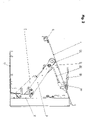
- the Figures 1 to 3 show the foot pedestal with its tread plate 1, the angle elements 32; 33 and the base plate 2. Between the footplate 1 and the base plate 2 are two support levers 3; 4 arranged, each having an upper and a lower bearing 8; 9 have.
- the lower bearing 9 has a connecting bolt 5 which has brackets 35; 36; 37; 38 on the spacers 20; 21 is attached.
- the gas pressure spring 7 or the threaded spindle 60 have the lower attachment point on the bearing 13, which via the brackets 39; 40 is attached to the base plate 2.
- the two support levers 3; 4 have at their respective upper ends the connecting bolt 10, to which at least one roller 14 is attached, which is guided on the underside of the footplate 1 in a supportive manner.
- the stepping plate 1 is guided in its upper region on both sides in a structure 24; 25 that is offset by 90° and runs on one side in a U-shaped guide 22; 23;
- the three-point bearing according to the invention is designed in such a way that the distance between the upper and lower bearings 8; 9 of the two support levers 3; 4 and between the lower bearing 9 of the two support levers 3; 4 and the lower attachment point/bearing 13 of the gas pressure spring or the Threaded spindle 7 has a ratio of ⁇ 8 to 1.
- This very special design is the only way to ensure that the gas pressure spring 7 or the threaded spindle 60 can be moved back up from the lower position (FIG. 3) via the electric drive 41 without any particular effort.
- the upper bearing 8 of the support levers 8; 9 executes a circular path.
- the construction 24; 25, which is offset by 90°, then slides in the respective U-shaped guide 22; 23, guided in a stable manner, upwards.
- the three-point bearing according to the invention acts in the form of a triangle, which ensures that the three bearings are always at the same distance from one another when the foot pedestal moves up and down.
- This construction ensures a great deal of stability against lateral twisting and a very easy up and down movement of the foot pedestal, even for women.
- the structure 24 used for the vertical guidance of the treadle 1; 25 is attached to the rear wall 31.
- the footplate 1 has at least one stop 6 at its lower end.
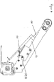
- the electric drive 41 with the threaded spindle 60 has an electric motor 42 which is connected to the threaded spindle 60 via a gear 43 and a spindle wheel 46 .
- the gear 43 and the spindle wheel 46 are integrated in a housing 50 .
- a joint eye 55 accommodating the threaded spindle 60 and having the bore 56 is fastened to the housing 50 .
Landscapes
- Engineering & Computer Science (AREA)
- Automation & Control Theory (AREA)
- Transportation (AREA)
- Mechanical Engineering (AREA)
- Passenger Equipment (AREA)
- Fluid-Damping Devices (AREA)
- Vehicle Step Arrangements And Article Storage (AREA)
Abstract
die Höhenverstellung der Trittplatte (1) des Fußpodestes als gelenkige Dreipunkt-Lagerung ausgeführt ist,
- wobei zwischen der Tritt- und der Bodenplatte (1;2) zwei parallel angeordnete Traghebel (3; 4) befindlich sind, die jeweils ein oberes sowie ein unteres Lager (8;9) aufweisen und das obere Lager (8) auf einen zwischen den Traghebeln (3; 4) befestigten Verbindungsbolzen (5) angeordnet ist, an dem eine Aufnahme (11) für den oberen Befestigungspunkt (12) einer Gasdruckfeder (7) oder einer Gewindespindel (60) eines elektrischen Antriebs (41) angeordnet ist und die Gasdruckfeder oder Gewindespindel (60) als unteren Befestigungspunkt ein weiteres Lager (13) aufweist, welches auf der Bodenplatte (2) über Halterungen (39;40) aufsitzt,
- wobei beide Traghebel (3;4) an ihren jeweiligen oberen Enden einen sie verbindenden weiteren Verbindungsbolzen (10) aufweisen, an dem mindestens eine Rolle (14) befestigt ist, die an der Unterseite der Trittplatte (1) stützend geführt ist,
- wobei im unteren Bereich beider Traghebel (3;4) jeweils ein Element als Festpunkt (15; 16) - bei der Verwendung einer Gasdruckfeder (7) - für jeweils eine Torsionsfeder (17; 18) angeordnet ist, wobei diese auf einem im unteren Lager angeordneten Bolzen (19) geführt ist, der beidseitig über Halterungen (34; 35; 36; 36; 37) auf mindestens zwei auf der Bodenplatte (2) aufsitzenden Distanzstücken (20; 21) befestigt ist, wobei die Distanzstücken (20; 21) als zweiter Festpunkt für die Torsionsfedern (17; 18) und - bei Verwendung eines elektrischen Antriebs (41) mit einer Gewindespindel (60) - jeweils ein Endlagenschalter (57; 58) mit jeweils einem Hebel (59) angeordnet sind,
- wobei die Trittplatte (1) in ihrem oberen Bereich beidseitig in einer jeweils um 90° versetzten und auf einer Seite in einer U-förmigen Führung (22;23) laufenden jeweiligen Konstruktion (24;25) vertikal beweglich geführt ist.
Description
- Die Erfindung betrifft ein Fußpodest mit höhenverstellbarer Trittplatte zum Führen eines Fahrzeuges, wobei das Fußpodest zumindest eine Trittplatte, einen elektrischen Antrieb und eine Bodenplatte aufweist.
- Üblicherweise wird bei einem Schienenfahrzeug ein Fahrersitz verwendet, der höhenverstellbar ist, um eine Anpassung an die unterschiedlichen Größen der Lokomotivführer herbeizuführen. Hierzu wird eine Fußstütze verwendet, die ebenfalls höhenverstellbar ist, damit der Fahrzeugführer seine Füße abstellen und ggfs. Pedale per Fuß betätigen kann, die auf der Trittplatte angebracht werden können.
- Aus der
EP 1 375 288 B1 ist ein höhenverstellbares Podest bekannt, bei dem ein Gleitschlitten vertikal gegen eine Basis abgestützt ist und mithilfe einer Gasdruckfeder über einen Fußhebel in vertikaler Richtung verstellbar ist. - Die
EP 3 065 990 B1 beschreibt ein Fußpodest mit einem schwenkbar gelagerten Fußabsetzelement, das sich an seiner Unterseite auf einer Gasdruckfeder abstützt und eine mechanisch betätigbare Arretiereinrichtung mit einem federbelasteten Verriegelungselement aufweist. - Weitere Schriften zum Stand der Technik sind das deutsche Gebrauchsmuster
DE 29 813 118 U1 sowie die US-PatentanmeldungUS 2012/0 112 035 A1 . - Aus der
DE 10 2012 216 561 B3 ist höhenverstellbare Fußstütze für ein Schienenfahrzeug bekannt. Die Fußstütze besitzt ein erstes Gehäuseteil, welches als Basisgehäuse dient sowie ein zweites Gehäuseteil, welches als Aufnahmegehäuse für eine Antriebseinrichtung, aufweisend einen elektrischen Antrieb und eine Gewindewelle, dient und ein drittes Gehäuseteil, welches als Abdeckgehäuse dient. - Ebenfalls bekannt ist eine verstellbare Fußraste für Lokführer oder Straßenbahnfahrer mit einem Podest, Gestell oder Rahmen und einer schwenkbar geführten Hebe- bzw. Senkeinheit, die an einen Antrieb gekoppelt ist, wobei zwei schwenkbar geführte Gelenke, die aus unteren und oberen Armen bestehen parallellogramm artig zusammenwirken (
PL 225 552 B1 PL 225 516 B1 PL 225 463 B1 - Auch die
PL 218 034 B1 - Die
EP 2 637 894 B1 , dieDE 20 2016 004 888 U1 und dieCN 1 07 901 928 A beschreiben ein höhenverstellbares Podest, welches umfasst:
eine höhenverstellbare Podestplattform, eine Federeinheit, welche eine Federkraft gemäß einer entsprechenden Federkennlinie bereitstellt und einen Hebelmechanismus, welcher zwischen der Federeinheit und der Podestplattform derart zwischengeschaltet ist, dass die Federkraft durch den Hebelmechanismus auf die Podestplattform auf eine solche Weise übertragen wird, dass eine Hubkraft bereitgestellt wird, welche der Gewichtskraft der Podestplattform entgegenwirkt, um die Höhenverstellung der Podestplattform zu erleichtern. - Des Weiteren ist aus der
DE 10 2018 207 035 A1 und derCN 1 09 278779 A ein modulares Fußpodest bekannt, wobei das Fußpodest zumindest einen Grundrahmen, welcher einen Höhenverstellmechanismus, einen auf einem Grundrahmen angebrachten Zwischenrahmen, eine Gasdruckfeder und ein Trittbrett aufweist. - Die in verschiedenen Konstruktionen verwendeten Gasdruckfedern sind in der untersten Position des Fußpodestes nahezu horizontal zusammengefahren. Die Fußpodeste lassen sich aufgrund der verwendeten Konstruktionen aus dieser Position nur sehr kompliziert wieder ausfahren und verklemmen sich oftmals. Dies stellt für kleinere Personen ein erhebliches Problem in der Handhabbarkeit der Fußpodeste dar.
- Die bekannten vergleichbaren Vorrichtungen weisen folgende Nachteile auf:
- sie sind oftmals nicht autonom betreibbar, sondern erfordern fahrzeugseitige Leitungen zur Versorgung / Steuerung,
- sie sind nicht ausreichend belastbar,
- sie sind teuer in der Herstellung,
- sie erfordern eine große Teilevielfalt,
- sie sind aufwendig zu warten,
- sie erfordern einen vertikalen Rahmen, wodurch sich die für den Fahrer verfügbare Fläche der Trittplatte dadurch verringert
- sie sind nur mit viel Krafteinwirkungen absenkbar, also für Frauen oftmals ungeeignet und
- sie sind - insbesondere als Scherenkonstruktionen - anfällig gegen unterhalb der Trittplatte anfallenden Verschmutzungen sowie gegen niedrige Temperaturen < 9°C.
- Der Erfindung liegt die Aufgabe zugrunde, ein Fußpodest mit höhenverstellbarer Trittplatte zum Führen eines Schienenfahrzeuges zu entwickeln, das weitgehend autonom betreibbar, dessen Trittplatte in der gesamten Hub- und Senkbewegung leichtgängig stufenlos beweglich, arretier- und belastbar ist und sich ohne Verklemmungserscheinungen auch aus der untersten Position problemlos wieder ausfahren lässt.
- Dies wird erfindungsgemäß dadurch erreicht, dass die Höhenverstellung der Trittplatte (1) des Fußpodestes als gelenkige Dreipunkt-Lagerung ausgeführt ist,
- wobei zwischen der Tritt- und der Bodenplatte (1;2) zwei parallel angeordnete Traghebel (3; 4) befindlich sind, die jeweils ein oberes sowie ein unteres Lager (8;9) aufweisen und das obere Lager (8) auf einen zwischen den Traghebeln (3; 4) befestigten Verbindungsbolzen (5) angeordnet ist, an dem eine Aufnahme (11) für den oberen Befestigungspunkt (12) einer Gasdruckfeder (7) oder einer Gewindespindel (60) eines elektrischen Antriebs (41) angeordnet ist und die Gasdruckfeder oder Gewindespindel (60) als unteren Befestigungspunkt ein weiteres Lager (13) aufweist, welches auf der Bodenplatte (2) über Halterungen (39;40) aufsitzt,
- wobei beide Traghebel (3;4) an ihren jeweiligen oberen Enden einen sie verbindenden weiteren Verbindungsbolzen (10) aufweisen, an dem mindestens eine Rolle (14) befestigt ist, die an der Unterseite der Trittplatte (1) stützend geführt ist,
- wobei im unteren Bereich beider Traghebel (3;4) jeweils ein Element als Festpunkt (15; 16) - bei der Verwendung einer Gasdruckfeder (7) - für jeweils eine Torsionsfeder (17; 18) angeordnet ist, wobei diese auf einem im unteren Lager angeordneten Bolzen (19) geführt ist, der beidseitig über Halterungen (34; 35; 36; 36; 37) auf mindestens zwei auf der Bodenplatte (2) aufsitzenden Distanzstücken (20; 21) befestigt ist, wobei die Distanzstücken (20; 21) als zweiter Festpunkt für die Torsionsfedern (17; 18) dient und - bei Verwendung eines elektrischen Antriebs (41) mit einer Gewindespindel (60) - jeweils ein Endlagenschalter (57; 58) mit jeweils einem Hebel (59) angeordnet sind,
- wobei die Trittplatte (1) in ihrem oberen Bereich beidseitig in einer jeweils um 90° versetzten und auf einer Seite in einer U-förmigen Führung (22;23) laufenden jeweiligen Konstruktion (24;25) vertikal beweglich geführt ist.
- Dabei ist die Dreipunkt-Lagerung so ausgebildet, dass der Abstand zwischen dem oberen und dem unteren Lager der beiden Traghebel sowie zwischen dem unteren Lager der beiden Traghebel und dem unteren Befestigungspunkt (Drehpunkt) der Gasdruckfeder oder der Gewindespindel ein Verhältnis von < 8 zu 1 aufweist. Dieses Verhältnis bleibt in allen Stellungen der Trittplatte gleich. Dabei führt das obere Lager in seiner Bewegung nach oben und nach unten jeweils einen Kreisbogen aus.
- Über die Dreipunkt-Lagerung wird ein Dreieck gebildet.
- Die erfindungsgemäße Ausbildung der Dreipunkt-Lagerung führt dazu, dass die Trittplatte aus ihrer unteren Position, bei einer nahezu horizontalen Position der Gasdruckfeder oder der Gewindespindel mit elektrischem Antrieb im eingefahrenen Zustand leicht und völlig problemlos auszufahren ist.
- Das Getriebe und das Spindelrad des elektrischen Antriebs sind in einem Gehäuse integriert.
- Am Gehäuse ist ein die Gewindespindel aufnehmendes Verlängerungsrohr mit einem Gelenkauge befestigt, wobei das Gelenkauge eine Bohrung aufweist.
- Die zur vertikalen Führung der Trittplatte verwendete Konstruktion ist an einer Rückwand befestigt.
- Die erfindungsgemäße Lösung weist folgende Vorteile auf:
- das Fußpodest ist weitgehend autonom betreibbar, mit 100 kg belastbar und die Trittplatte ist stufenlos höhenverstell- und arretierbar,
- das gesamte Fußpodest ist einfach aufgebaut und hat ein geringes Gewicht,
- die Konstruktion ist wartungsfrei,
- der Einfahr- und Ausfahrmechanismus ist aufgrund der Dreigelenk-Lagerung leichtgängig,
- die Konstruktion ist preiswert und weist wenige Bauteile auf,
- die Konstruktion ist wenig empfindlich gegen Verschmutzungen,
- die Hub-Konstruktion ist sehr sicher und stabil vertikal geführt
- sie ist unempfindlich gegen niedrige Temperaturen.
- Nachfolgend soll die Erfindung anhand eines Ausführungsbeispiels näher erläutert werden.
- Dabei zeigt:
-
Figur 1 - die Vorrichtung unter Verwendung einer Gasdruckfeder in 3D-Darstellung im ausgefahrenen Zustand -
Figur 2 - die Vorrichtung unter Verwendung einer Gasdruckfeder in der Seitenansicht im ausgefahrenen Zustand -
Figur 3 - die Vorrichtung unter Verwendung einer Gasdruckfeder in 3D-Ansicht im eingefahrenen Zustand -
Figur 4 - die Vorrichtung unter Verwendung eines elektrischen Antriebs mit Gewindespindel in der Seitenansicht im ausgefahrenen Zustand -
Figur 5 - den elektrischen Antrieb mit seinen Bauteilen in der Seitenansicht - Die
Figuren 1 bis 3 zeigen das Fußpodest mit seiner Trittplatte 1, den Winkelelementen 32; 33 und der Bodenplatte 2. Zwischen der Trittplatte 1 und der Bodenplatte 2 sind zwei Traghebel 3; 4 angeordnet, die jeweils ein oberes und ein unteres Lager 8; 9 aufweisen. - Das untere Lager 9 weist einen Verbindungsbolzen 5 auf, der über Halterungen 35; 36; 37; 38 auf den Distanzstücken 20; 21 befestigt ist.
- Am Verbindungsbolzen 5, der auch als oberes Lager 8 fungiert, ist die Aufnahme 11 befestigt, in die der oberer Befestigungspunkt 12 der Gasdruckfeder 7 oder der Gewindespindel 60 eingebunden ist (
Figur 2 ). Die Gasdruckfeder 7 oder die Gewindespindel 60 weisen als unteren Befestigungspunkt das Lager 13 auf, welches über die Halterungen 39; 40 an der Bodenplatte 2 befestigt ist. - Die beiden Traghebel 3;4 weisen an ihren jeweiligen oberen Enden den Verbindungsbolzen 10 auf, an dem mindestens eine Rolle 14 befestigt sind, die an der Unterseite der Trittplatte 1 stützend geführt ist.
- Die Trittplatte 1 ist in ihrem oberen Bereich beidseitig in einer jeweils um 90° versetzten und auf einer Seite in einer U-förmigen Führung 22;23 laufenden Konstruktion 24;25 vertikal beweglich geführt.
- Die erfindungsgemäße Dreipunktlagerung ist dabei so ausgebildet, dass der Abstand zwischen dem oberen und dem unteren Lager 8;9 der beiden Traghebel 3;4 sowie zwischen dem unteren Lager 9 der beiden Traghebel 3;4 und dem unteren Befestigungspunkt / Lager 13 der Gasdruckfeder oder der Gewindespindel 7 ein Verhältnis von <8 zu 1 aufweist. Nur durch diese sehr spezielle Ausführung ist es gewährleistet, dass sich die Gasdruckfeder 7 oder die Gewindespindel 60 über den elektrischen Antrieb 41 aus der unteren Position (Figur 3) ohne besondere Aufwendungen wieder nach oben führen lässt. Das obere Lager 8 der Traghebel 8;9 führt dabei eine kreisförmige Bahn aus. Die um 90° versetzt ausgebildete Konstruktion 24;25 gleitet dann in der jeweiligen U-förmigen Führung 22;23 stabil geführt nach oben.
- Die erfindungsgemäße Dreipunkt-Lagerung wirkt dabei in Form eines Dreieckes, welches absichert, dass sich bei Auf- und Abwärtsbewegungen des Fußpodestes die drei Lager immer im gleichen Abstandsverhältnis zueinander befinden.
- Diese Konstruktion wiederum sichert sehr viel Stabilität gegen seitliche Verwindungen und ein sehr leichtes Auf- und Abwärtsbewegen des Fußpodestes auch für Frauen ab.
- Die zur vertikalen Führung der Trittplatte 1 verwendete Konstruktion 24; 25 ist an der Rückwand 31 befestigt.
- Die Trittplatte 1 weist an ihrem unteren Ende mindestens einen Anschlag 6 auf.
- Bei Verwendung eines elektrischen Antriebs 41 (
Figur 4 und5 ) mit Gewindespindel 60 anstelle der Gashubfeder 7 bleibt die Gesamtkonstruktion nahezu unverändert bestehen, wobei die Torsionsfedern 17; 18 entfallen können. Auch der Auslöser 28 mit Feder 26, Aufnahme 29 und Bowdenzug 30 können dann entfallen. - Der elektrische Antrieb 41 mit Gewindespindel 60 weist dabei einen Elektromotor 42 auf, der über ein Getriebe 43 und ein Spindelrad 46 mit der Gewindespindel 60 verbunden ist.
- Das Getriebe 43 und das Spindelrad 46 sind in einem Gehäuse 50 integriert.
- Am Gehäuse 50 ist ein die Gewindespindel 60 aufnehmendes Gelenkauge 55 befestigt, welches die Bohrung 56 aufweist.
-
- 1 -
- Trittplatte
- 2 -
- Bodenplatte
- 3 -
- Traghebel
- 4 -
- Traghebelj
- 5 -
- Verbindungsbolzen
- 6 -
- Anschlag
- 7 -
- Gewindespindel
- 8 -
- oberes Lager
- 9 -
- unteres Lager
- 10 -
- Verbindungsbolzen
- 11 -
- Aufnahme
- 12 -
- oberer Befestigungspunkt
- 13 -
- unterer Befestigungspunkt / Lager
- 14 -
- Rolle
- 15 -
- Festpunkt
- 16 -
- Festpunkt
- 17 -
- Torsionsfeder
- 18 -
- Torsionsfeder
- 19 -
- Bolzen
- 20 -
- Distanzstück
- 21 -
- Distanzstück
- 22 -
- U-förmige Führung
- 23 -
- U-förmige Führung
- 24 -
- Konstruktion
- 25 -
- Konstruktion
- 26 -
- Feder
- 27 -
- frei
- 28 -
- Auslöser
- 29 -
- Aufnahme
- 30 -
- Bowdenzug
- 31 -
- Rückwand
- 32 -
- frei
- 33 -
- frei
- 35 -
- Halterung
- 36 -
- Halterung
- 37 -
- Halterung
- 38 -
- Halterung
- 39 -
- Halterung
- 40 -
- Halterung
- 41 -
- elektrischer Antrieb
- 42 -
- Elektromotor
- 43 -
- Getriebe
- 44 -
- frei
- 45 -
- frei
- 46 -
- Spindelrad
- 47 -
- frei
- 48 -
- frei
- 49 -
- frei
- 50 -
- Gehäuse
- 51 -
- frei
- 52 -
- frei
- 53 -
- frei
- 54 -
- Verlängerungsrohr
- 55 -
- Gelenkauge
- 56 -
- Bohrung
- 57 -
- Endlagenschalter
- 58 -
- Endlagenschalter
- 59 -
- Hebel
Claims (8)
- Fußpodest mit höhenverstellbarer Trittplatte zum Führen eines Fahrzeuges, wobei das Fußpodest zumindest eine Trittplatte, eine Gasdruckfeder und eine Bodenplatte aufweist,
gekennzeichnet dadurch, dass
die Höhenverstellung der Trittplatte (1) des Fußpodestes als gelenkige Dreipunkt-Lagerung ausgeführt ist,- wobei zwischen der Tritt- und der Bodenplatte (1;2) zwei parallel angeordnete Traghebel (3; 4) befindlich sind, die jeweils ein oberes sowie ein unteres Lager (8;9) aufweisen und das obere Lager (8) auf einen zwischen den Traghebeln (3; 4) befestigten Verbindungsbolzen (5) angeordnet ist, an dem eine Aufnahme (11) für den oberen Befestigungspunkt (12) einer Gasdruckfeder (7) oder einer Gewindespindel (60) eines elektrischen Antriebs (41) angeordnet ist und die Gasdruckfeder oder Gewindespindel (60) als unteren Befestigungspunkt ein weiteres Lager (13) aufweist, welches auf der Bodenplatte (2) über Halterungen (39;40) aufsitzt,- wobei beide Traghebel (3;4) an ihren jeweiligen oberen Enden einen sie verbindenden weiteren Verbindungsbolzen (10) aufweisen, an dem mindestens eine Rolle (14) befestigt ist, die an der Unterseite der Trittplatte (1) stützend geführt ist,- wobei im unteren Bereich beider Traghebel (3;4) jeweils ein Element als Festpunkt (15; 16) - bei der Verwendung einer Gasdruckfeder (7) - für jeweils eine Torsionsfeder (17; 18) angeordnet ist, wobei diese auf einem im unteren Lager angeordneten Bolzen (19) geführt ist, der beidseitig über Halterungen (34; 35; 36; 36; 37) auf mindestens zwei auf der Bodenplatte (2) aufsitzenden Distanzstücken (20; 21) befestigt ist, wobei die Distanzstücken (20; 21) als zweiter Festpunkt für die Torsionsfedern (17; 18) und - bei Verwendung eines elektrischen Antriebs (41) mit einer Gewindespindel (60) - jeweils ein Endlagenschalter (57; 58) mit jeweils einem Hebel (59) angeordnet sind,- wobei die Trittplatte (1) in ihrem oberen Bereich beidseitig in einer jeweils um 90° versetzten und auf einer Seite in einer U-förmigen Führung (22;23) laufenden jeweiligen Konstruktion (24;25) vertikal beweglich geführt ist. - Fußpodest nach Anspruch 1, gekennzeichnet dadurch, dass die Dreipunkt-Lagerung so ausgebildet ist, dass der Abstand zwischen dem oberen und dem unteren Lager (8;9) der beiden Traghebel (3;4) sowie zwischen dem unteren Lager (9) der beiden Traghebel (3;4) und dem unteren Befestigungspunkt / Lager (13) der Gasdruckfeder (7) oder der Gewindespindel (60) ein Verhältnis von < 8 zu 1 aufweist.
- Fußpodest nach Anspruch 1 bis 2, gekennzeichnet dadurch, dass die Dreipunkt-Lagerung als ein Dreieck ausgebildet ist.
- Fußpodest nach Anspruch 1 bis 3, gekennzeichnet dadurch, dass bei Verwendung einer Gasdruckfeder (7) zur stufenlosen Arretierung der Trittplatte (1) in verschiedenen Positionen die Trittplatte (1) einen gelenkig zu betätigenden Auslöser (28) mit Feder (26) aufweist, der an seiner Unterseite eine Aufnahme (29) für einen Bowdenzug (30) besitzt, wobei der Bowdenzug (30) an seinem anderen Ende am Auslösekopf der Gasdruckfeder (7) befestigt ist.
- Fußpodest nach Anspruch 1 bis 3, gekennzeichnet dadurch, dass bei Verwendung eines elektrischen Antriebs (41) dieser einen Elektromotor (42) aufweist, der über ein Getriebe (43) und ein Spindelrad (46) mit der Gewindespindel (60) verbunden ist.
- Fußpodest nach Anspruch 1 bis 3 und 5, gekennzeichnet dadurch, dass der Elektromotor (42), das Getriebe (43) und das Spindelrad (46) in einem Gehäuse (50) integriert sind.
- Fußpodest nach Anspruch 1 bis 3 sowie 5 und 6, gekennzeichnet dadurch, dass am Gehäuse (50) ein die Gewindespindel (60) aufnehmendes Verlängerungsrohr (54) mit einem Gelenkauge (55) befestigt ist, wobei das Gelenkauge (55) eine Bohrung (56) aufweist.
- Fußpodest nach Anspruch 1 bis 7, gekennzeichnet dadurch, dass die zur vertikalen Führung der Trittplatte (1) verwendete jeweilige Konstruktion (22; 23) an einer Rückwand (31) befestigt ist.
Applications Claiming Priority (1)
| Application Number | Priority Date | Filing Date | Title |
|---|---|---|---|
| DE102021000173 | 2021-01-15 |
Publications (2)
| Publication Number | Publication Date |
|---|---|
| EP4029756A1 true EP4029756A1 (de) | 2022-07-20 |
| EP4029756B1 EP4029756B1 (de) | 2023-09-20 |
Family
ID=82218296
Family Applications (1)
| Application Number | Title | Priority Date | Filing Date |
|---|---|---|---|
| EP22000006.1A Active EP4029756B1 (de) | 2021-01-15 | 2022-01-05 | Fusspodest mit höhenverstellbarer trittplatte zum führen eines fahrzeugs |
Country Status (2)
| Country | Link |
|---|---|
| EP (1) | EP4029756B1 (de) |
| DE (1) | DE102021005953A1 (de) |
Cited By (2)
| Publication number | Priority date | Publication date | Assignee | Title |
|---|---|---|---|---|
| CN116513249A (zh) * | 2023-06-01 | 2023-08-01 | 湖南联诚轨道装备有限公司 | 一种轨道机车用电动升降脚踏 |
| CN117184144A (zh) * | 2023-09-08 | 2023-12-08 | 湖南联诚轨道装备有限公司 | 一种轨道机车用电动升降脚踏 |
Citations (14)
| Publication number | Priority date | Publication date | Assignee | Title |
|---|---|---|---|---|
| DE29813118U1 (de) | 1998-07-23 | 1998-10-01 | VTD Verkehrstechnik Datteln Stahl- und Maschinenbau GmbH, 45711 Datteln | Fußpodest für Schienenfahrzeuge |
| EP1375288B1 (de) | 2002-06-10 | 2007-03-07 | Tever Technik Vertriebs- und Beteiligungs-GmbH & Co. Beratungs KG | Höhenverstellbares Podest |
| US20120112035A1 (en) | 2010-11-09 | 2012-05-10 | Tever Technik Vertriebs-und Beteiligungs-GmbH & Co. Beratungs KG | Height-Adjustable Pedestal |
| DE102012216561B3 (de) | 2012-09-17 | 2013-12-24 | GSI Manufaktur GmbH | Fußstütze für ein Schienenfahrzeug |
| PL218034B1 (pl) | 2010-11-03 | 2014-09-30 | Zutmar Spółka Z Ograniczoną Odpowiedzialnością | Podnóżek motorniczego albo maszynisty |
| EP2637894B1 (de) | 2010-11-09 | 2015-02-18 | Tever Technik Vertriebs- und Beteiligungs-GmbH & Co. Beratungs KG | Höhenverstellbarer sockel |
| WO2015106807A1 (de) * | 2014-01-15 | 2015-07-23 | Siemens Aktiengesellschaft | Fusspodest und arbeitstisch mit einem fusspodest |
| DE202016004888U1 (de) | 2016-08-10 | 2016-10-19 | Tever Technik GmbH & Co. KG | Fußpodest mit höhenverstellbarer Trittplatte zum Führen eines Fahrzeuges, vorzugsweise eines Schienenfahrzeuges |
| PL225516B1 (pl) | 2013-12-20 | 2017-04-28 | Ec Eng Spółka Z Ograniczoną Odpowiedzialnością | Regulowany podnóżek maszynisty lub motorniczego |
| PL225552B1 (pl) | 2013-12-20 | 2017-04-28 | Ec Eng Spółka Z Ograniczoną Odpowiedzialnością | Regulowany podnóżek maszynisty lub motorniczego |
| PL225463B1 (pl) | 2013-12-20 | 2017-04-28 | Ec Eng Spółka Z Ograniczoną Odpowiedzialnością | Regulowany podnóżek maszynisty lub motorniczego |
| CN107901928A (zh) | 2017-11-08 | 2018-04-13 | 中车长春轨道客车股份有限公司 | 一种城市轨道车辆可调节式司机脚踏 |
| CN109278779A (zh) | 2018-11-30 | 2019-01-29 | 中车青岛四方车辆研究所有限公司 | 脚踏升降调节装置 |
| DE102018207035A1 (de) | 2018-05-07 | 2019-11-07 | Siemens Aktiengesellschaft | Modulares Fußpodest für einen Führerstand eines Schienenfahrzeugs |
-
2021
- 2021-12-02 DE DE102021005953.0A patent/DE102021005953A1/de not_active Withdrawn
-
2022
- 2022-01-05 EP EP22000006.1A patent/EP4029756B1/de active Active
Patent Citations (16)
| Publication number | Priority date | Publication date | Assignee | Title |
|---|---|---|---|---|
| DE29813118U1 (de) | 1998-07-23 | 1998-10-01 | VTD Verkehrstechnik Datteln Stahl- und Maschinenbau GmbH, 45711 Datteln | Fußpodest für Schienenfahrzeuge |
| EP1375288B1 (de) | 2002-06-10 | 2007-03-07 | Tever Technik Vertriebs- und Beteiligungs-GmbH & Co. Beratungs KG | Höhenverstellbares Podest |
| PL218034B1 (pl) | 2010-11-03 | 2014-09-30 | Zutmar Spółka Z Ograniczoną Odpowiedzialnością | Podnóżek motorniczego albo maszynisty |
| US20120112035A1 (en) | 2010-11-09 | 2012-05-10 | Tever Technik Vertriebs-und Beteiligungs-GmbH & Co. Beratungs KG | Height-Adjustable Pedestal |
| EP2637894B1 (de) | 2010-11-09 | 2015-02-18 | Tever Technik Vertriebs- und Beteiligungs-GmbH & Co. Beratungs KG | Höhenverstellbarer sockel |
| DE102012216561B3 (de) | 2012-09-17 | 2013-12-24 | GSI Manufaktur GmbH | Fußstütze für ein Schienenfahrzeug |
| PL225516B1 (pl) | 2013-12-20 | 2017-04-28 | Ec Eng Spółka Z Ograniczoną Odpowiedzialnością | Regulowany podnóżek maszynisty lub motorniczego |
| PL225552B1 (pl) | 2013-12-20 | 2017-04-28 | Ec Eng Spółka Z Ograniczoną Odpowiedzialnością | Regulowany podnóżek maszynisty lub motorniczego |
| PL225463B1 (pl) | 2013-12-20 | 2017-04-28 | Ec Eng Spółka Z Ograniczoną Odpowiedzialnością | Regulowany podnóżek maszynisty lub motorniczego |
| WO2015106807A1 (de) * | 2014-01-15 | 2015-07-23 | Siemens Aktiengesellschaft | Fusspodest und arbeitstisch mit einem fusspodest |
| EP3065990B1 (de) | 2014-01-15 | 2019-12-25 | Siemens Mobility GmbH | Fusspodest und arbeitstisch mit einem fusspodest |
| DE202016004888U1 (de) | 2016-08-10 | 2016-10-19 | Tever Technik GmbH & Co. KG | Fußpodest mit höhenverstellbarer Trittplatte zum Führen eines Fahrzeuges, vorzugsweise eines Schienenfahrzeuges |
| CN107901928A (zh) | 2017-11-08 | 2018-04-13 | 中车长春轨道客车股份有限公司 | 一种城市轨道车辆可调节式司机脚踏 |
| CN107901928B (zh) * | 2017-11-08 | 2020-03-06 | 中车长春轨道客车股份有限公司 | 一种城市轨道车辆可调节式司机脚踏 |
| DE102018207035A1 (de) | 2018-05-07 | 2019-11-07 | Siemens Aktiengesellschaft | Modulares Fußpodest für einen Führerstand eines Schienenfahrzeugs |
| CN109278779A (zh) | 2018-11-30 | 2019-01-29 | 中车青岛四方车辆研究所有限公司 | 脚踏升降调节装置 |
Cited By (2)
| Publication number | Priority date | Publication date | Assignee | Title |
|---|---|---|---|---|
| CN116513249A (zh) * | 2023-06-01 | 2023-08-01 | 湖南联诚轨道装备有限公司 | 一种轨道机车用电动升降脚踏 |
| CN117184144A (zh) * | 2023-09-08 | 2023-12-08 | 湖南联诚轨道装备有限公司 | 一种轨道机车用电动升降脚踏 |
Also Published As
| Publication number | Publication date |
|---|---|
| EP4029756B1 (de) | 2023-09-20 |
| DE102021005953A1 (de) | 2022-07-21 |
Similar Documents
| Publication | Publication Date | Title |
|---|---|---|
| EP2452664B1 (de) | Operationstisch | |
| DD205649A5 (de) | Hubvorrichtung fuer fahrzeuge, insbesondere fuer benachteiligte | |
| DE102007062406A1 (de) | Gehhilfe mit Antriebsmodul | |
| EP3768564B1 (de) | Modulares fusspodest für einen führerstand eines schienenfahrzeugs | |
| EP1293378A2 (de) | Sitzeinrichtung in einem minengeschützten Kampffahrzeug | |
| EP4029756B1 (de) | Fusspodest mit höhenverstellbarer trittplatte zum führen eines fahrzeugs | |
| DE202016004888U1 (de) | Fußpodest mit höhenverstellbarer Trittplatte zum Führen eines Fahrzeuges, vorzugsweise eines Schienenfahrzeuges | |
| DE19935008B4 (de) | Gabelniederhubwagen | |
| DE20318319U1 (de) | Rollstuhl | |
| DE19815444C1 (de) | Tisch, insbesondere für Bildschirmarbeitsplätze | |
| DE2533398C3 (de) | Vorrichtung zum Anheben von Kraftfahrzeugen | |
| EP1071003A2 (de) | Pedal für ein Kraftfahrzeug | |
| EP2044916B2 (de) | Trittplattenvorrichtung | |
| DE202015101359U1 (de) | Maximal absenkbares Pflegebett | |
| DE9416172U1 (de) | Montagevorrichtung für Fahrzeuge | |
| DE10306626A1 (de) | Fahrzeugsitz mit einer Sitzhöhen- und einer Sitzkissenneigungsverstellung | |
| DE2050694A1 (de) | Flugpassagier Uberfuhrungsfahrzeug | |
| DE102014100451B4 (de) | Vorrichtung zum Verfahren eines Transporters einer Patientenlagereinheit und Anordnung mit einer derartigen Vorrichtung | |
| DE69911480T2 (de) | Grundkörper für eine Arbeitshebebühne | |
| DE102009019163A1 (de) | Gabelstapler mit Fahrerschutzdach | |
| DE2914350C2 (de) | Aufzugseinrichtung | |
| DE20307043U1 (de) | Stufenlos höhenverstellbarer universell anpaßbarer Stuhl | |
| EP0016452A1 (de) | Transportvorrichtung | |
| DE3874118T2 (de) | Bewegliches schnelles rettungssystem fuer kabelbahnen. | |
| DE29619988U1 (de) | Patientenlifter mit mechanischer Notabsenkung |
Legal Events
| Date | Code | Title | Description |
|---|---|---|---|
| PUAI | Public reference made under article 153(3) epc to a published international application that has entered the european phase |
Free format text: ORIGINAL CODE: 0009012 |
|
| STAA | Information on the status of an ep patent application or granted ep patent |
Free format text: STATUS: THE APPLICATION HAS BEEN PUBLISHED |
|
| AK | Designated contracting states |
Kind code of ref document: A1 Designated state(s): AL AT BE BG CH CY CZ DE DK EE ES FI FR GB GR HR HU IE IS IT LI LT LU LV MC MK MT NL NO PL PT RO RS SE SI SK SM TR |
|
| STAA | Information on the status of an ep patent application or granted ep patent |
Free format text: STATUS: REQUEST FOR EXAMINATION WAS MADE |
|
| 17P | Request for examination filed |
Effective date: 20221223 |
|
| GRAP | Despatch of communication of intention to grant a patent |
Free format text: ORIGINAL CODE: EPIDOSNIGR1 |
|
| STAA | Information on the status of an ep patent application or granted ep patent |
Free format text: STATUS: GRANT OF PATENT IS INTENDED |
|
| INTG | Intention to grant announced |
Effective date: 20230524 |
|
| GRAS | Grant fee paid |
Free format text: ORIGINAL CODE: EPIDOSNIGR3 |
|
| GRAA | (expected) grant |
Free format text: ORIGINAL CODE: 0009210 |
|
| STAA | Information on the status of an ep patent application or granted ep patent |
Free format text: STATUS: THE PATENT HAS BEEN GRANTED |
|
| AK | Designated contracting states |
Kind code of ref document: B1 Designated state(s): AL AT BE BG CH CY CZ DE DK EE ES FI FR GB GR HR HU IE IS IT LI LT LU LV MC MK MT NL NO PL PT RO RS SE SI SK SM TR |
|
| REG | Reference to a national code |
Ref country code: GB Ref legal event code: FG4D Free format text: NOT ENGLISH |
|
| REG | Reference to a national code |
Ref country code: CH Ref legal event code: EP |
|
| REG | Reference to a national code |
Ref country code: IE Ref legal event code: FG4D Free format text: LANGUAGE OF EP DOCUMENT: GERMAN |
|
| REG | Reference to a national code |
Ref country code: DE Ref legal event code: R096 Ref document number: 502022000139 Country of ref document: DE |
|
| REG | Reference to a national code |
Ref country code: LT Ref legal event code: MG9D |
|
| PG25 | Lapsed in a contracting state [announced via postgrant information from national office to epo] |
Ref country code: GR Free format text: LAPSE BECAUSE OF FAILURE TO SUBMIT A TRANSLATION OF THE DESCRIPTION OR TO PAY THE FEE WITHIN THE PRESCRIBED TIME-LIMIT Effective date: 20231221 |
|
| REG | Reference to a national code |
Ref country code: NL Ref legal event code: MP Effective date: 20230920 |
|
| PG25 | Lapsed in a contracting state [announced via postgrant information from national office to epo] |
Ref country code: SE Free format text: LAPSE BECAUSE OF FAILURE TO SUBMIT A TRANSLATION OF THE DESCRIPTION OR TO PAY THE FEE WITHIN THE PRESCRIBED TIME-LIMIT Effective date: 20230920 Ref country code: RS Free format text: LAPSE BECAUSE OF FAILURE TO SUBMIT A TRANSLATION OF THE DESCRIPTION OR TO PAY THE FEE WITHIN THE PRESCRIBED TIME-LIMIT Effective date: 20230920 Ref country code: NO Free format text: LAPSE BECAUSE OF FAILURE TO SUBMIT A TRANSLATION OF THE DESCRIPTION OR TO PAY THE FEE WITHIN THE PRESCRIBED TIME-LIMIT Effective date: 20231220 Ref country code: LV Free format text: LAPSE BECAUSE OF FAILURE TO SUBMIT A TRANSLATION OF THE DESCRIPTION OR TO PAY THE FEE WITHIN THE PRESCRIBED TIME-LIMIT Effective date: 20230920 Ref country code: LT Free format text: LAPSE BECAUSE OF FAILURE TO SUBMIT A TRANSLATION OF THE DESCRIPTION OR TO PAY THE FEE WITHIN THE PRESCRIBED TIME-LIMIT Effective date: 20230920 Ref country code: HR Free format text: LAPSE BECAUSE OF FAILURE TO SUBMIT A TRANSLATION OF THE DESCRIPTION OR TO PAY THE FEE WITHIN THE PRESCRIBED TIME-LIMIT Effective date: 20230920 Ref country code: GR Free format text: LAPSE BECAUSE OF FAILURE TO SUBMIT A TRANSLATION OF THE DESCRIPTION OR TO PAY THE FEE WITHIN THE PRESCRIBED TIME-LIMIT Effective date: 20231221 Ref country code: FI Free format text: LAPSE BECAUSE OF FAILURE TO SUBMIT A TRANSLATION OF THE DESCRIPTION OR TO PAY THE FEE WITHIN THE PRESCRIBED TIME-LIMIT Effective date: 20230920 |
|
| PG25 | Lapsed in a contracting state [announced via postgrant information from national office to epo] |
Ref country code: NL Free format text: LAPSE BECAUSE OF FAILURE TO SUBMIT A TRANSLATION OF THE DESCRIPTION OR TO PAY THE FEE WITHIN THE PRESCRIBED TIME-LIMIT Effective date: 20230920 |
|
| PG25 | Lapsed in a contracting state [announced via postgrant information from national office to epo] |
Ref country code: IS Free format text: LAPSE BECAUSE OF FAILURE TO SUBMIT A TRANSLATION OF THE DESCRIPTION OR TO PAY THE FEE WITHIN THE PRESCRIBED TIME-LIMIT Effective date: 20240120 |
|
| PG25 | Lapsed in a contracting state [announced via postgrant information from national office to epo] |
Ref country code: ES Free format text: LAPSE BECAUSE OF FAILURE TO SUBMIT A TRANSLATION OF THE DESCRIPTION OR TO PAY THE FEE WITHIN THE PRESCRIBED TIME-LIMIT Effective date: 20230920 |
|
| PG25 | Lapsed in a contracting state [announced via postgrant information from national office to epo] |
Ref country code: SM Free format text: LAPSE BECAUSE OF FAILURE TO SUBMIT A TRANSLATION OF THE DESCRIPTION OR TO PAY THE FEE WITHIN THE PRESCRIBED TIME-LIMIT Effective date: 20230920 Ref country code: RO Free format text: LAPSE BECAUSE OF FAILURE TO SUBMIT A TRANSLATION OF THE DESCRIPTION OR TO PAY THE FEE WITHIN THE PRESCRIBED TIME-LIMIT Effective date: 20230920 Ref country code: IS Free format text: LAPSE BECAUSE OF FAILURE TO SUBMIT A TRANSLATION OF THE DESCRIPTION OR TO PAY THE FEE WITHIN THE PRESCRIBED TIME-LIMIT Effective date: 20240120 Ref country code: ES Free format text: LAPSE BECAUSE OF FAILURE TO SUBMIT A TRANSLATION OF THE DESCRIPTION OR TO PAY THE FEE WITHIN THE PRESCRIBED TIME-LIMIT Effective date: 20230920 Ref country code: EE Free format text: LAPSE BECAUSE OF FAILURE TO SUBMIT A TRANSLATION OF THE DESCRIPTION OR TO PAY THE FEE WITHIN THE PRESCRIBED TIME-LIMIT Effective date: 20230920 Ref country code: CZ Free format text: LAPSE BECAUSE OF FAILURE TO SUBMIT A TRANSLATION OF THE DESCRIPTION OR TO PAY THE FEE WITHIN THE PRESCRIBED TIME-LIMIT Effective date: 20230920 Ref country code: SK Free format text: LAPSE BECAUSE OF FAILURE TO SUBMIT A TRANSLATION OF THE DESCRIPTION OR TO PAY THE FEE WITHIN THE PRESCRIBED TIME-LIMIT Effective date: 20230920 Ref country code: PT Free format text: LAPSE BECAUSE OF FAILURE TO SUBMIT A TRANSLATION OF THE DESCRIPTION OR TO PAY THE FEE WITHIN THE PRESCRIBED TIME-LIMIT Effective date: 20240122 |
|
| PG25 | Lapsed in a contracting state [announced via postgrant information from national office to epo] |
Ref country code: PL Free format text: LAPSE BECAUSE OF FAILURE TO SUBMIT A TRANSLATION OF THE DESCRIPTION OR TO PAY THE FEE WITHIN THE PRESCRIBED TIME-LIMIT Effective date: 20230920 Ref country code: IT Free format text: LAPSE BECAUSE OF FAILURE TO SUBMIT A TRANSLATION OF THE DESCRIPTION OR TO PAY THE FEE WITHIN THE PRESCRIBED TIME-LIMIT Effective date: 20230920 |
|
| REG | Reference to a national code |
Ref country code: DE Ref legal event code: R097 Ref document number: 502022000139 Country of ref document: DE |
|
| PG25 | Lapsed in a contracting state [announced via postgrant information from national office to epo] |
Ref country code: DK Free format text: LAPSE BECAUSE OF FAILURE TO SUBMIT A TRANSLATION OF THE DESCRIPTION OR TO PAY THE FEE WITHIN THE PRESCRIBED TIME-LIMIT Effective date: 20230920 |
|
| PLBE | No opposition filed within time limit |
Free format text: ORIGINAL CODE: 0009261 |
|
| STAA | Information on the status of an ep patent application or granted ep patent |
Free format text: STATUS: NO OPPOSITION FILED WITHIN TIME LIMIT |
|
| PG25 | Lapsed in a contracting state [announced via postgrant information from national office to epo] |
Ref country code: DK Free format text: LAPSE BECAUSE OF FAILURE TO SUBMIT A TRANSLATION OF THE DESCRIPTION OR TO PAY THE FEE WITHIN THE PRESCRIBED TIME-LIMIT Effective date: 20230920 |
|
| REG | Reference to a national code |
Ref country code: DE Ref legal event code: R119 Ref document number: 502022000139 Country of ref document: DE |
|
| PG25 | Lapsed in a contracting state [announced via postgrant information from national office to epo] |
Ref country code: MC Free format text: LAPSE BECAUSE OF FAILURE TO SUBMIT A TRANSLATION OF THE DESCRIPTION OR TO PAY THE FEE WITHIN THE PRESCRIBED TIME-LIMIT Effective date: 20230920 |
|
| 26N | No opposition filed |
Effective date: 20240621 |
|
| PG25 | Lapsed in a contracting state [announced via postgrant information from national office to epo] |
Ref country code: MC Free format text: LAPSE BECAUSE OF FAILURE TO SUBMIT A TRANSLATION OF THE DESCRIPTION OR TO PAY THE FEE WITHIN THE PRESCRIBED TIME-LIMIT Effective date: 20230920 |
|
| PG25 | Lapsed in a contracting state [announced via postgrant information from national office to epo] |
Ref country code: LU Free format text: LAPSE BECAUSE OF NON-PAYMENT OF DUE FEES Effective date: 20240105 |
|
| PG25 | Lapsed in a contracting state [announced via postgrant information from national office to epo] |
Ref country code: LU Free format text: LAPSE BECAUSE OF NON-PAYMENT OF DUE FEES Effective date: 20240105 |
|
| PG25 | Lapsed in a contracting state [announced via postgrant information from national office to epo] |
Ref country code: DE Free format text: LAPSE BECAUSE OF NON-PAYMENT OF DUE FEES Effective date: 20240801 |
|
| PG25 | Lapsed in a contracting state [announced via postgrant information from national office to epo] |
Ref country code: BE Free format text: LAPSE BECAUSE OF NON-PAYMENT OF DUE FEES Effective date: 20240131 |
|
| PG25 | Lapsed in a contracting state [announced via postgrant information from national office to epo] |
Ref country code: FR Free format text: LAPSE BECAUSE OF NON-PAYMENT OF DUE FEES Effective date: 20240131 |
|
| PG25 | Lapsed in a contracting state [announced via postgrant information from national office to epo] |
Ref country code: SI Free format text: LAPSE BECAUSE OF FAILURE TO SUBMIT A TRANSLATION OF THE DESCRIPTION OR TO PAY THE FEE WITHIN THE PRESCRIBED TIME-LIMIT Effective date: 20230920 |
|
| PG25 | Lapsed in a contracting state [announced via postgrant information from national office to epo] |
Ref country code: SI Free format text: LAPSE BECAUSE OF FAILURE TO SUBMIT A TRANSLATION OF THE DESCRIPTION OR TO PAY THE FEE WITHIN THE PRESCRIBED TIME-LIMIT Effective date: 20230920 Ref country code: FR Free format text: LAPSE BECAUSE OF NON-PAYMENT OF DUE FEES Effective date: 20240131 Ref country code: DE Free format text: LAPSE BECAUSE OF NON-PAYMENT OF DUE FEES Effective date: 20240801 Ref country code: BE Free format text: LAPSE BECAUSE OF NON-PAYMENT OF DUE FEES Effective date: 20240131 |
|
| REG | Reference to a national code |
Ref country code: BE Ref legal event code: MM Effective date: 20240131 |
|
| PG25 | Lapsed in a contracting state [announced via postgrant information from national office to epo] |
Ref country code: BG Free format text: LAPSE BECAUSE OF FAILURE TO SUBMIT A TRANSLATION OF THE DESCRIPTION OR TO PAY THE FEE WITHIN THE PRESCRIBED TIME-LIMIT Effective date: 20230920 |
|
| PG25 | Lapsed in a contracting state [announced via postgrant information from national office to epo] |
Ref country code: BG Free format text: LAPSE BECAUSE OF FAILURE TO SUBMIT A TRANSLATION OF THE DESCRIPTION OR TO PAY THE FEE WITHIN THE PRESCRIBED TIME-LIMIT Effective date: 20230920 |
|
| PG25 | Lapsed in a contracting state [announced via postgrant information from national office to epo] |
Ref country code: IE Free format text: LAPSE BECAUSE OF NON-PAYMENT OF DUE FEES Effective date: 20240105 |
|
| PG25 | Lapsed in a contracting state [announced via postgrant information from national office to epo] |
Ref country code: IE Free format text: LAPSE BECAUSE OF NON-PAYMENT OF DUE FEES Effective date: 20240105 |
|
| PG25 | Lapsed in a contracting state [announced via postgrant information from national office to epo] |
Ref country code: CY Free format text: LAPSE BECAUSE OF FAILURE TO SUBMIT A TRANSLATION OF THE DESCRIPTION OR TO PAY THE FEE WITHIN THE PRESCRIBED TIME-LIMIT; INVALID AB INITIO Effective date: 20220105 |
|
| REG | Reference to a national code |
Ref country code: CH Ref legal event code: PL |
|
| PG25 | Lapsed in a contracting state [announced via postgrant information from national office to epo] |
Ref country code: CH Free format text: LAPSE BECAUSE OF NON-PAYMENT OF DUE FEES Effective date: 20250131 |
|
| PG25 | Lapsed in a contracting state [announced via postgrant information from national office to epo] |
Ref country code: TR Free format text: LAPSE BECAUSE OF FAILURE TO SUBMIT A TRANSLATION OF THE DESCRIPTION OR TO PAY THE FEE WITHIN THE PRESCRIBED TIME-LIMIT Effective date: 20230920 |
|
| PGFP | Annual fee paid to national office [announced via postgrant information from national office to epo] |
Ref country code: AT Payment date: 20260301 Year of fee payment: 5 |
|
| PG25 | Lapsed in a contracting state [announced via postgrant information from national office to epo] |
Ref country code: CH Free format text: THE PATENT HAS BEEN ANNULLED BY A DECISION OF A NATIONAL AUTHORITY Effective date: 20250131 |
|
| PG25 | Lapsed in a contracting state [announced via postgrant information from national office to epo] |
Ref country code: HU Free format text: LAPSE BECAUSE OF FAILURE TO SUBMIT A TRANSLATION OF THE DESCRIPTION OR TO PAY THE FEE WITHIN THE PRESCRIBED TIME-LIMIT; INVALID AB INITIO Effective date: 20220105 |