EP4027222A1 - Display system and method - Google Patents
Display system and method Download PDFInfo
- Publication number
- EP4027222A1 EP4027222A1 EP22158760.3A EP22158760A EP4027222A1 EP 4027222 A1 EP4027222 A1 EP 4027222A1 EP 22158760 A EP22158760 A EP 22158760A EP 4027222 A1 EP4027222 A1 EP 4027222A1
- Authority
- EP
- European Patent Office
- Prior art keywords
- end user
- head movement
- augmented reality
- frame
- reality system
- Prior art date
- Legal status (The legal status is an assumption and is not a legal conclusion. Google has not performed a legal analysis and makes no representation as to the accuracy of the status listed.)
- Pending
Links
Images


Classifications
-
- G—PHYSICS
- G06—COMPUTING OR CALCULATING; COUNTING
- G06T—IMAGE DATA PROCESSING OR GENERATION, IN GENERAL
- G06T19/00—Manipulating three-dimensional [3D] models or images for computer graphics
- G06T19/006—Mixed reality
-
- G—PHYSICS
- G06—COMPUTING OR CALCULATING; COUNTING
- G06F—ELECTRIC DIGITAL DATA PROCESSING
- G06F3/00—Input arrangements for transferring data to be processed into a form capable of being handled by the computer; Output arrangements for transferring data from processing unit to output unit, e.g. interface arrangements
- G06F3/01—Input arrangements or combined input and output arrangements for interaction between user and computer
- G06F3/011—Arrangements for interaction with the human body, e.g. for user immersion in virtual reality
- G06F3/012—Head tracking input arrangements
-
- G—PHYSICS
- G02—OPTICS
- G02B—OPTICAL ELEMENTS, SYSTEMS OR APPARATUS
- G02B27/00—Optical systems or apparatus not provided for by any of the groups G02B1/00 - G02B26/00, G02B30/00
- G02B27/0093—Optical systems or apparatus not provided for by any of the groups G02B1/00 - G02B26/00, G02B30/00 with means for monitoring data relating to the user, e.g. head-tracking, eye-tracking
-
- G—PHYSICS
- G02—OPTICS
- G02B—OPTICAL ELEMENTS, SYSTEMS OR APPARATUS
- G02B27/00—Optical systems or apparatus not provided for by any of the groups G02B1/00 - G02B26/00, G02B30/00
- G02B27/01—Head-up displays
-
- G—PHYSICS
- G02—OPTICS
- G02B—OPTICAL ELEMENTS, SYSTEMS OR APPARATUS
- G02B27/00—Optical systems or apparatus not provided for by any of the groups G02B1/00 - G02B26/00, G02B30/00
- G02B27/01—Head-up displays
- G02B27/017—Head mounted
-
- G—PHYSICS
- G02—OPTICS
- G02B—OPTICAL ELEMENTS, SYSTEMS OR APPARATUS
- G02B27/00—Optical systems or apparatus not provided for by any of the groups G02B1/00 - G02B26/00, G02B30/00
- G02B27/01—Head-up displays
- G02B27/017—Head mounted
- G02B27/0172—Head mounted characterised by optical features
-
- G—PHYSICS
- G06—COMPUTING OR CALCULATING; COUNTING
- G06F—ELECTRIC DIGITAL DATA PROCESSING
- G06F3/00—Input arrangements for transferring data to be processed into a form capable of being handled by the computer; Output arrangements for transferring data from processing unit to output unit, e.g. interface arrangements
- G06F3/01—Input arrangements or combined input and output arrangements for interaction between user and computer
- G06F3/011—Arrangements for interaction with the human body, e.g. for user immersion in virtual reality
- G06F3/013—Eye tracking input arrangements
-
- G—PHYSICS
- G06—COMPUTING OR CALCULATING; COUNTING
- G06T—IMAGE DATA PROCESSING OR GENERATION, IN GENERAL
- G06T1/00—General purpose image data processing
- G06T1/60—Memory management
-
- G—PHYSICS
- G06—COMPUTING OR CALCULATING; COUNTING
- G06T—IMAGE DATA PROCESSING OR GENERATION, IN GENERAL
- G06T19/00—Manipulating three-dimensional [3D] models or images for computer graphics
-
- G—PHYSICS
- G06—COMPUTING OR CALCULATING; COUNTING
- G06T—IMAGE DATA PROCESSING OR GENERATION, IN GENERAL
- G06T7/00—Image analysis
- G06T7/70—Determining position or orientation of objects or cameras
-
- G—PHYSICS
- G09—EDUCATION; CRYPTOGRAPHY; DISPLAY; ADVERTISING; SEALS
- G09G—ARRANGEMENTS OR CIRCUITS FOR CONTROL OF INDICATING DEVICES USING STATIC MEANS TO PRESENT VARIABLE INFORMATION
- G09G3/00—Control arrangements or circuits, of interest only in connection with visual indicators other than cathode-ray tubes
- G09G3/007—Use of pixel shift techniques, e.g. by mechanical shift of the physical pixels or by optical shift of the perceived pixels
-
- G—PHYSICS
- G02—OPTICS
- G02B—OPTICAL ELEMENTS, SYSTEMS OR APPARATUS
- G02B27/00—Optical systems or apparatus not provided for by any of the groups G02B1/00 - G02B26/00, G02B30/00
- G02B27/01—Head-up displays
- G02B27/0101—Head-up displays characterised by optical features
- G02B2027/014—Head-up displays characterised by optical features comprising information/image processing systems
-
- G—PHYSICS
- G02—OPTICS
- G02B—OPTICAL ELEMENTS, SYSTEMS OR APPARATUS
- G02B27/00—Optical systems or apparatus not provided for by any of the groups G02B1/00 - G02B26/00, G02B30/00
- G02B27/01—Head-up displays
- G02B27/017—Head mounted
- G02B2027/0178—Eyeglass type
-
- G—PHYSICS
- G02—OPTICS
- G02B—OPTICAL ELEMENTS, SYSTEMS OR APPARATUS
- G02B27/00—Optical systems or apparatus not provided for by any of the groups G02B1/00 - G02B26/00, G02B30/00
- G02B27/01—Head-up displays
- G02B27/0179—Display position adjusting means not related to the information to be displayed
- G02B2027/0187—Display position adjusting means not related to the information to be displayed slaved to motion of at least a part of the body of the user, e.g. head, eye
-
- G—PHYSICS
- G06—COMPUTING OR CALCULATING; COUNTING
- G06F—ELECTRIC DIGITAL DATA PROCESSING
- G06F2203/00—Indexing scheme relating to G06F3/00 - G06F3/048
- G06F2203/01—Indexing scheme relating to G06F3/01
- G06F2203/012—Walk-in-place systems for allowing a user to walk in a virtual environment while constraining him to a given position in the physical environment
-
- G—PHYSICS
- G06—COMPUTING OR CALCULATING; COUNTING
- G06T—IMAGE DATA PROCESSING OR GENERATION, IN GENERAL
- G06T2219/00—Indexing scheme for manipulating 3D models or images for computer graphics
- G06T2219/024—Multi-user, collaborative environment
-
- G—PHYSICS
- G09—EDUCATION; CRYPTOGRAPHY; DISPLAY; ADVERTISING; SEALS
- G09G—ARRANGEMENTS OR CIRCUITS FOR CONTROL OF INDICATING DEVICES USING STATIC MEANS TO PRESENT VARIABLE INFORMATION
- G09G2320/00—Control of display operating conditions
- G09G2320/02—Improving the quality of display appearance
- G09G2320/0266—Reduction of sub-frame artefacts
Definitions
- the present invention generally relates to systems and methods configured to facilitate interactive virtual or augmented reality environments for one or more users.
- a number of display systems can benefit from information regarding the head pose of a viewer or user (i.e., the orientation and/or location of user's head).
- head-worn displays or helmet-mounted displays, or smart glasses
- head-worn displays are at least loosely coupled to a user's head, and thus move when the user's head moves. If the user's head motions are detected by the display system, the data being displayed can be updated to take the change in head pose into account.
- a user wearing a head-worn display views a virtual representation of a 3D object on the display and walks around the area where the 3D object appears, that 3D object can be re-rendered for each viewpoint, giving the user the perception that he or she is walking around an object that occupies real space.
- the head-worn display is used to present multiple objects with a virtual space (for instance, a rich virtual world)
- measurements of head pose can be used to re-render the scene to match the user's dynamically changing head location and orientation and provide an increased sense of immersion in the virtual space.
- the accuracy of head-tracking is high and that the overall system latency is very low from the first detection of head motion to the updating of the light that is delivered by the display to the user's visual system. If the latency is high, the system can create a mismatch between the user's vestibular and visual sensory systems, and generate motion sickness or simulator sickness.
- Some head-worn displays enable the concurrent viewing of real and virtual elements-an approach often described as augmented reality or mixed reality.
- a camera captures elements of a real scene
- a computing system superimposes virtual elements onto the captured real scene
- a non-transparent display presents the composite image to the eyes.
- Another configuration is often referred to as an "optical see-through” display, in which the user can see through transparent (or semi-transparent) elements in the display system to view directly the light from real objects in the environment.
- the transparent element often referred to as a "combiner" superimposes light from the display over the user's view of the real world.
- detection of head pose can enable the display system to render virtual objects such that they appear to occupy a space in the real world.
- the virtual objects are re-rendered as a function of head pose, such that the virtual objects appear to remain stable relative to the real world.
- the user's view of the real world has essentially a zero latency while his or her view of the virtual objects has a latency that depends on the head-tracking rate, processing time, rendering time, and display frame rate. If the system latency is high, the apparent location of virtual objects will appear unstable during rapid head motions.
- head-worn display systems In addition to head-worn display systems, other display systems can benefit from accurate and low latency head pose detection. These include head-tracked display systems in which the display is not worn on the user's body, but is, e.g., mounted on a wall or other surface. The head-tracked display acts like a window onto a scene, and as a user moves his head relative the "window" the scene is re-rendered to match the user's changing viewpoint. Other systems include a head-worn projection system, in which a head-worn display projects light onto the real world.
- Embodiments of the present invention are directed to devices, systems and methods for facilitating virtual reality and/or augmented reality interaction for one or more users.
- One embodiment is directed to a method of operation in a virtual image system or an augmented reality system, the method comprising, for each of at least some of a plurality of frames being presented to an end user, determining a location of appearance of a virtual object in a field of view of the end user relative to an end user frame of reference, and adjusting a presentation of at least one subsequent frame based at least in part on the determined location of appearance of the virtual object in the field of view of the end user.
- the virtual object may be newly introduced in the field of view of the end user temporally relative to previous frames presented to the end user.
- the newly introduced virtual object may be determined to likely attract an attention of the end user.
- the virtual object may be in a new position in the frame relative to a position in at least one previous frame. Or, the virtual object may be in a new position as presented to the end user relative to a previous position of the virtual object as previously presented to the end user.
- the method may further comprise selecting the virtual object based on input indicative of an attention of the end user to the virtual object.
- the input indicative of the attention of the end user to the virtual object may be based at least in part on an appearance of the virtual object in a new position as presented to the end user relative to a position of the virtual object as previously presented to the end user.
- the input indicative of the attention of the end user to the virtual object may be based at least in part on how quickly a position of the virtual object as presented to the end user changes relative to the position of the virtual object as previously presented to the end user.
- the adjusting of the presentation of the at least one subsequent frame may include presenting the at least one subsequent frame with a center of the at least one subsequent frame shifted toward the determined location of appearance of the virtual object in the field of view of the end user.
- the adjusting of the presentation of the at least one subsequent frame may include presenting the at least one subsequent frame with a center of the at least one subsequent frame shifted to the determined location of appearance of the virtual object in the field of view of the end user.
- the method may further comprise predicting an occurrence of a head movement of the end user based at least in part on the determined location of appearance of the virtual object in the field of view of the end user.
- the method may further comprise estimating at least one value indicative of an estimated speed of the predicted head movement of the end user, determining at least one value that at least partially compensates for the estimated speed of the predicted head movement of the end user, and rendering the at least one subsequent frame based at least in part on the determined value.
- the method may further comprise estimating at least one change in the speed in the predicted head movement of the end user, wherein the at least one change in the speed occurs between a start of the predicted head movement and an end of the predicted head movement, and wherein estimating the at least one value indicative of the estimated speed of the predicted head movement includes estimating the at least one value indicative of the estimated speed that at least partially accommodates for the estimated changes in the speed in the predicted head movement of the end user.
- the estimating of the at least one change in the speed in the predicted head movement of the end user may include estimating the at least one change between a first defined time after the start of the predicted head movement and a second defined time before the end of the predicted head movement.
- the method may further comprise estimating at least one value indicative of an estimated acceleration of the predicted head movement of the end user, determining at least one value that at least partially compensates for the estimated acceleration of the predicted head movement of the end user, and rendering the at least one subsequent frame based at least in part on the determined value.
- the method may further comprise receiving information indicative of an identity of the end user, and retrieving at least one user specific historical attribute for the end user based on the received information indicative of the identity of the end user, wherein the user specific historical attribute is indicative of at least one of a previous head movement speed for the end user, a previous head movement acceleration for the end user, and a previous eye movement to head movement relationship for the end user.
- the virtual object may be at least one of a virtual text object, a virtual numeric object, a virtual alphanumeric object, a virtual tag object, a virtual field object, a virtual chart object, a virtual map object, a virtual instrumentation object or a virtual visual representation of a physical object.
- Another embodiment is directed to a method of operation in an augmented reality system, the method comprising receiving information indicative of an identity of the end user, retrieving at least one user specific historical attribute for the end user based at least in part on the received information indicative of the identity of the end user, and providing frames to the end user based at least in part on the retrieved at least one user specific historical attribute for the end user.
- the received information may be image information indicative of an image of at least a portion of an eye of the end user.
- the retrieved at least one user specific historical attribute for the end user may be at least one attribute that provides an indication of at least one head movement attribute for the end user, wherein the head movement attribute is indicative of at least one previous head movement of the end user.
- the retrieved at least one user specific historical attribute for the end user may be at least one attribute that provides an indication of at least one previous head movement speed for at least one previous head movement for the end user.
- the retrieved at least one user specific historical attribute for the end user may be at least one attribute that provides an indication of variation in a head movement speed across at least part of a range of at least one previous head movement by the end user.
- the retrieved at least one user specific historical attribute for the end user may be at least one attribute that provides an indication of at least one previous head movement acceleration for at least one previous head movement by the end user.
- the retrieved at least one user specific historical attribute for the end user may be at least one attribute that provides an indication of a relationship between at least one previous head movement and at least one previous eye movement by the end user.
- the retrieved at least one user specific historical attribute for the end user may be at least one attribute that provides an indication of a ratio between at least one previous head movement and at least one previous eye movement by the end user.
- the method may further comprise predicting at least an end point of a head movement of the end user, and providing frames to the end user based at least in part on the retrieved at least one user specific historical attribute for the end user includes rendering at least one subsequent frame to at least one image buffer, the at least one subsequent frame shifted toward the predicted end point of the head movement.
- the method may, further comprise rendering a plurality of subsequent frames that shift toward the predicted end point of the head movement in at least partial accommodation of at least one head movement attribute for the end user, the head movement attribute indicative of at least one previous head movement of the end user.
- the head movement attribute indicative of at least one previous head movement of the end user may be a historical head movement speed, a historical head movement acceleration for the end user or a historical ratio between head movement and eye movement for the end user.
- the method may further comprise predicting an occurrence of a head movement of the end user based at least in part on a location of appearance of the virtual object in the field of view of the end user.
- the location of appearance of the virtual object may be determined in the same manner described above.
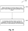
- Another embodiment is directed to detecting an indication that a spacing as presented to an end user between some pixels in a frame will differ from a spacing between other pixels in the frame, adjusting a first set of pixels based on the detected indication, and providing at least a portion of at least one subsequent frame with the adjusted first set of pixels to at least partially compensate for the difference in spacing as presented to the end user.
- the pixel characteristics e.g., size, intensity, etc.
- the method may further comprise selecting a first set of pixels of the frame based on a direction of the detected head movement, wherein the direction of the first set of pixels is the same as the direction of the detected head movement, and increasing a size of the first set of pixels of the at least one subsequent frame.
- the method may further comprise selecting a first set of pixels of the frame based on a direction of the detected head movement wherein the direction of the first set of pixels is the same as the direction of the detected head movement, and increasing an intensity of the first set of pixels of the at least one subsequent frame in response to the detected head movement.
- the method may further comprise selecting a first set of pixels of the frame based on a direction of the detected head movement wherein the direction of the first set of pixels is the opposite as the direction of the detected head movement, and decreasing a size of the first set of pixels of the at least one subsequent frame in response to the detected head movement.
- the method may further comprise selecting a first set of pixels of the frame based on a direction of the detected head movement wherein the direction of the first set of pixels is the opposite as the direction of the detected head movement, and decreasing an intensity of the first set of pixels of the at least one subsequent frame in response to the detected head movement.
- Another embodiment id directed to a method of operation in a virtual image presentation system, the method comprising rendering a first complete frame to an image buffer, wherein the first complete frame includes pixel information for sequential presentation of pixels to form an image of a virtual object, starting a presentation of the first complete frame, and dynamically interrupting the presenting of the first complete frame before completion of the presentation of the first complete frame by a presentation of an update to the first complete frame in which a portion of the pixel information has changed from the first complete frame.
- Another embodiment is directed to a method of operation in a virtual image presentation system, the method comprising rendering a first complete frame having a first field and a second field to an image buffer, wherein the first field includes at least a first spiral scan line and the second field includes at least a second spiral scan line, the second spiral scan line interlaced with at least the first spiral scan line, reading out of the frame buffer which stores the first complete frame, and dynamically interrupting the reading out of the first complete frame before completion of the reading of the first complete frame by a reading out of an update to the first complete frame in which a portion of the pixel information has changed from the first complete frame.
- the dynamic interruption of the reading out may be based on a detected head movement of an end user, wherein the detected head movement exceeds a nominal head movement value.
- Another embodiment is directed to a method of operation in a virtual image presentation system, the method comprising rendering a first complete frame having a first field and a second field to an image buffer, wherein the first field includes at least a first Lissajous scan line and the second field includes at least a second Lissajous scan line, the second Lissajous scan line interlaced with at least the first Lissajous scan line, reading out of the frame buffer which stores the first complete frame, and dynamically interrupting, based on a detected head movement of an end user exceeding a nominal head movement value, the reading out of the first complete frame before completion of the reading of the first complete frame by a reading out of an update to the first complete frame in which a portion of the pixel information has changed from the first complete frame.
- the method may further comprise phase shifting the Lissajous scan lines to interlace the Lissajous scan lines.
- Another embodiment is directed to a method of operation in a virtual image presentation system, the method comprising for each of a plurality of frames, determining a respective resolution for each of at least two portions of the respective frame in response to a detected head movement of an end user, and presenting the virtual objects based on the determined respective resolutions of the at least two portions of the respective frame.
- the portion of the respective frame may be at least one of a field of the frame, a line of the frame, a pixel of the frame.
- the method may further comprise adjusting a characteristic of a drive signal between presenting a first portion of a the frame and a second portion of the frame to create a variable resolution in the image of the virtual object.
- the characteristic of the drive signal may be at least one of an amplitude of the drive signal and a slope of the drive signal.
- the method may further comprise assessing a point of attention in at least a first image for the end user, based on at least one of a processed eye tracking data, a determined location of appearance of a virtual object in a field of view of the end user relative to an end user frame of reference, a determined location of appearance of the virtual object when newly introduced in the field of view of the end user, and a determined location of appearance of the virtual object in a new position in an image relative to a position of the virtual object in at least one previous image.
- the method may further comprise increasing the resolution in at least one subsequent image in a portion of the at least one subsequent image that is at least proximate to the assessed point of attention relative to other portions of the at least one subsequent image.
- the method may further comprise decreasing the resolution in at least one subsequent image in a portion of the at least one subsequent image that is distal to the assessed point of attention relative to other portions of the at least one subsequent image.
- Another embodiment is directed to a method of operation in a virtual image presentation system, the method comprising displaying at least one virtual object to an end user, and temporarily blanking a portion of the display of the at least one virtual object when at least one of a detected head movement exceeds a nominal head movement value and a predicted head movement is predicted to exceed a head movement value.
- the method may further comprise processing head tracking data supplied via at least one transducer to determine the at least one of the detected head movement and the predicted head movement, wherein the head tracking data indicative of at least an orientation of a head of the end user.
- Another embodiment is directed to a projector apparatus to project at least virtual images in an augmented reality system
- the projector apparatus comprising a projector element, a support that supports the projector element with the projector element moveable in at least one axis of freedom, at least one actuator coupled to selectively move the projector element, and a control subsystem communicatively coupled to control the actuator such that the projector element is moved in response to at least one of a detection of a head movement of an end user that exceeds a nominal head movement value and a prediction of a head movement of the end user that is predicted to exceed the nominal head movement value.
- the projector element may further comprise at least a first optical fiber, the first optical fiber having a back end and a front end, the back end coupled to receive images, the front end positioned to transmit images therefrom.
- the support element may comprise a piezoelectric collar that receives at least the first optical fiber proximate but spaced rear-wardly from the front end of the first optical fiber such that a portion of the first optical fiber proximate the front end thereof extends from the piezoelectric collar and is free to oscillate with a defined resonance frequency.
- the projector apparatus of claim 87 wherein the at least on control subsystem is communicatively coupled to receive head tracking data supplied via at least one transducer, the head tracking data indicative of at least an orientation of a head of the end user.
- the control subsystem for each of at least some of a plurality of images presented to the end user, determines a location of appearance of a virtual object in a field of view of the end user relative to an end user frame of reference, assesses whether the determined location requires the end user to turn a head of the end user, and predicts the occurrence of the head movement based on the assessment.
- Another embodiment is directed to a method of operation in a virtual image presentation system, the method comprising over-rendering a frame for a defined field of view such that a pixel information for a set of pixels of the frame exceeds the maximum area of display at the maximum resolution, determining a portion of the frame to present to the end user based on at least one of a detected head movement and a predicted head movement, and selectively reading out only the determined portion of the frame.
- a user display device comprising a housing frame mountable on a head of a user, a lens mountable on the housing frame, and a projection subsystem coupled to the housing frame to determine a location of appearance of a display object in a field of view of the user based at least in part on at least one of a detection of a head movement of the user and a prediction of a head movement of the user, and to project the display object to the user based on the determined location of appearance of the display object.
- the location of appearance of the display object may be moved in response to the at least one of the detection of the head movement of the user or prediction of the head movement of the user that exceeds or it predicted to exceed a nominal head movement value.
- the prediction of the head movement of the user may be based on a prediction of a user's shift in focus or on a set historical attributes of the user.
- the user display device may further comprise a first pair of cameras mountable on the housing frame to track a movement of the user's eyes and estimate a depth of focus of the user's eyes based on the tracked eye movements.
- the projection subsystem may project the display object based on the estimated depth of focus.
- the user display device may further comprise a second pair of cameras mountable on the housing frame to capture a field of view image as seen by the user's eyes, wherein the field of view image contains at least one physical object.
- the projection sub system may project the display object in a manner such that the display object and the physical object captured through the second pair of cameras are inter-mixed and appear together in the same frame.
- the location of appearance may be based at least in part on the physical object.
- the display object and the physical object may have a predetermined relationship.
- the captured field of view image may be used to gather information regarding movements of the head of the user, wherein the information regarding movements of the head of the user comprises a center of attention of the user, an orientation of the head of the user, a direction of the head of the user, a speed of movement of the head of the user, an acceleration of the head of the user and a distance of the head of the user in relation to a local environment of the user.
- the lens may comprise at least one transparent surface to selectively allow a transmission light such that the user is able to view a local environment.
- the projection subsystem may project the display object in a manner such that the user views both the display object and the local environment as viewed through the transparent surface of the lens.
- the user display device may further comprise at least one intertial transducer to capture a set of intertial measurements indicative of movement of the head of the user, wherein the set of intertial measurements comprises a speed of movement of the head of the user, an acceleration of movement of the head of the user, a direction of movement of the head of the user, a position of the head of the user and an orientation of the head of the user.
- the user display device may further comprise at least one light source to illuminate at least one of the head of the user and a local environment of the user.
- the projection sub system may adjust at least one of a perceived size, an intensity and a resolution of a set of pixels associated with the display object to compensate for the at least one of the detected head movement and the predicted head movement.
- the display object may be one of a virtual object and an augmented virtual object.
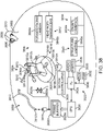
- Fig 38 shows a virtual image generation system 3800 which may operate to provide virtual images to an end user 3802, according to one illustrated embodiment.
- the virtual image generation system 3800 may be operated as an augmented reality system, providing images of virtual objects intermixed with physical objects in a field of view of the end user.
- a first approach employs one or more imagers (e.g., cameras) to capture images of the ambient environment.
- the virtual image generation system 3800 may inter-mix the virtual images into the data representing the images of the ambient environment.
- a second approach employs one or more at least partially transparent surfaces through which the ambient environment can be seen and on to which the virtual image generation system 3800 produces images of virtual objects.
- at least some of the aspects described herein are particularly suited to augmented reality systems.
- the virtual image generation system 3800 may be operated as a virtual reality system, providing images of virtual objects in a virtual environment.
- the virtual image generation system 3800 may be employed in applications other than augmented reality and virtual reality systems.
- various techniques may be applied to any projection or display system.
- the various techniques described herein may be applied to pico projectors where movement may be movement of an end user's hand rather than head movement.
- the teachings should not be limited to such systems or such uses.
- Virtual objects also referred to herein as virtual tags or tag or call outs, may take any of a large variety of forms, basically any variety of data, information, concept or logical construct capable of being represented as an image.
- Non-limiting examples of virtual objects may include: a virtual text object, a virtual numeric object, a virtual alphanumeric object, a virtual tag object, a virtual field object, a virtual chart object, a virtual map object, a virtual instrumentation object or a virtual visual representation of a physical object.
- Head tracking accuracy and latency have been problems for virtual reality and augmented reality systems. Tracking inaccuracies and latency produce inconsistency between the end user's visual system and vestibular system. Such may lead to queasiness and discomfort. Such is particularly problematic in display systems that fill a large portion of the end user's field of view. Approaches to addressing such may include increasing frame rate or effective frame rate, for instance via strobing or flashing or via other techniques. As described herein, predictive head tracking may be employed to address such, for instance by reducing latency. Predictive head tracking may rely on any of a large variety of factors or approaches, including historical data or attributes for a specific end user. Also as described herein, blanking of display or presentation may be effectively employed, for instance blanking during rapid head movements.
- placement of virtual objects in spatial relation to physical objects may be a nontrivial problem.
- head movement may significantly complicated placement of virtual objects in a view of an ambient environment. Such is true whether the view is captured as an image of the ambient environment and then projected or displayed to the end user 3802, or whether the end user 3802 perceives the view of the ambient environment directly.
- head movement will like cause a field of view of the end user 3802 to change, which will likely require an update to where various virtual objects are displayed in the field of view of the end user 3802.
- head movements may occur within a large variety of ranges and speeds.
- Head movement speed may vary not only between different head movements, but within or across the range of a single head movement. For instance, head movement speed may initially increase (e.g., linearly or not) from a starting point, and may decrease as a ending point is reached, obtaining a maximum speed somewhere between the starting and ending points of the head movement. Rapid head movements may even exceed the ability of the particular display or projection technology to render images that appear uniform and/or as smooth motion to the end user 3802.
- the virtual image generation system 3800 includes a projection subsystem 3804 operable to project images on a partially transparent display surface 3806 which is positioned in the end user's 3802 field of view between the eyes 3808of the end user 3802 and an ambient environment.
- the virtual image generation system 3800 may be worn or mounted on a head 3810 of the end user 3802, for example incorporated into a pair of glasses or a visor.
- the projection subsystem 3804 includes one or more optical fibers 3812 (e.g., single mode optical fiber) which have a back or distal end 3812a into which light is received and a front or proximate end 3812b from which light is provided to the partially transparent display surface 38063806 or projected directly into the eyes 3808 of the end user 3802.
- the projection subsystem 3804 may also include one or more light sources 3815 that produces the light (e.g., emits light of different colors in defined patterns), and communicatively couples the light to the back or distal end 3812a of the one or more optical fibers 3812.
- the light source(s) 3815 may take any of a large variety of forms, for instance a set of RGB lasers (e.g., laser diodes capable of outputting red, green and blue light) operable to respectively produce red, green and blue coherent collimated light according to a defined pixel patterns specified in respective frames of pixel information or data.
- RGB lasers e.g., laser diodes capable of outputting red, green and blue light
- Laser light provides high color saturation and are highly energy efficient.
- Fig. 38 shows a single optical fiber 3812
- some implementations may employ two or more optical fibers 3812, breaking the light up into multiple channels.
- the optical fibers 3812 may have staggered tips or beveled and polished tips to bend the light, reducing optical spacing between the channels.
- the optical fibers 3812 may be conveniently packaged as a ribbon cable. Suitable optics may produce a conjugate of the respective images produced by each of the channels.
- the one or more optical fibers 3812 may be supported by a yoke 3814 with a portion of the front or proximate end 3812b extending therefrom.
- the yoke 3814 may be operable to set the front or proximate end 3812b in oscillatory motion.
- the yoke 3814 may comprise a tube of a piezoelectric transducer 3814a (only one shown in Fig. 38 ).
- a number of electrodes 3813 are radially arranged about the piezoelectric transducer 3814a.
- Applying control signals, e.g., via frame buffer 3828, to respective electrodes 3813 associated with the piezoelectric transducer 3814a can cause the front or proximate end 3812b of the optical fiber(s) 3812 to oscillate vibrate in a first resonance mode.
- a size of vibrations or amount of travel off center is controllable via the applied drive signals to obtain any of a variety of at least bi-axial patterns. Patterns may, for instance, include a raster scan pattern, spiral or volute scan pattern, or a Lissajous or figure 8 scan pattern.
- Fig. 31 shows a frame 3100 of pixel information or data that specifies pixel information or data to present an image, for example, an image of one or more virtual objects, according to one illustrated embodiment.
- the frame 3100 is schematically illustrated with a cell 3100a,-3100n (only two called out, collectively 3102) each pixel. Sequences of cells arranged in rows or lines 3104a, 31004b-3100n (three called out, collectively 3104), illustrated as extending horizontally across the drawing sheet in Fig. 31 .
- the frame 3100 includes a plurality of lines 3104.
- Fig. 31 employs ellipses to represent missing information, such as cells or lines that have been omitted for clarity of illustration.
- Each cell 3102 of the frame 3100 may specify values (collectively 3106) for each of a plurality of colors for the respective pixel to which the cell corresponds and/or intensities.
- the frame 3100 may specify one or more values for red 3106a, one or more values for green 3106b and one or more values for blue 3106c for each pixel.
- the values 3106 may be specified as binary representations for each of the colors, for instance a respective 4 bit number for each color.
- Each cell 3102 of the frame 3100 may additionally include an amplitude or radial value #P06d that specifies an amplitude or radial dimension for each pixel, for example where the frame 3100 may be used with a spiral scan line pattern based system or with a Lissajous scan line pattern based system.
- the frame 3100 may include one or more fields, collectively 3110.
- the frame 3100 may consist of a single field.
- the frame 3100 may comprise two, or even more fields 3110a-3110b.
- the frame 3100 illustrated in Fig. 31 shows two fields 3110a-3110b.
- the pixel information for a complete first field 3110a of the frame 3100 may be specified before the pixel information for the complete second field 3110b, for example occurring before the pixel information for the second field 3110b in an array, an ordered list or other data structure (e.g., record, linked list).
- a third or even a fourth field may follow the second field 3110b, assuming a presentation system is configured to handle more than two fields 3110a-3110b.
- Fig. 32 schematically represents a raster scan pattern 3200.
- the raster scan pattern 3200 pixels 3202 (only one called out) are sequentially presented.
- the raster scan pattern 3200 typically presents pixels from left to right (indicated by arrows 3204a, 3204b, then from top to bottom (indicated by arrow 3206).
- the presentation may start at the upper right corner and traverse left across a first line 3208a until the end of the line is reached.
- the raster scan pattern 3200 typically then starts from the left in a next line down.
- the presentation may be temporarily blacked out or blanked which returning from the end of one line to the start of the next line.
- This process repeats line-by-line until the bottom line 3208n is completed, for example at the bottom right most pixel.
- a new frame is started, again returning the right of the top most line of the next frame. Again, the presentation may be blanked while returning from the bottom left to the top right to present the next frame.
- interlaced raster scan patterns lines from the first and the second fields 3210a, 3210b are interlaced.
- the pixel information for the first field 3210a may be used for the odd numbered lines only, while the pixel information for the second field 3210b may be used for the even numbered lines only.
- all of the lines of the first field 3210a of the frame 3100 are typically presented before the lines of the second field 3210b.
- the first field 3210a may be presented using the pixel information of the first field 3210a to sequentially present line 1, line 3, line 5, etc.
- the second field 3210b of the frame 3100 may be presented following the first field 3210a, by using the pixel information of the second field 3210b to sequentially present line 2, line 4, line 6, etc.
- Fig. 33 schematically represents a spiral scan pattern 3300, according to one illustrated embodiment.
- the spiral scan pattern 3300 may consist of a single spiral scan line 3302, which may include one or more complete angular cycles (e.g., 360 degrees) which may be denominated as coils or loops.
- the pixel information is used to specify the color and/or intensity of each sequential pixel, as the angle increments.
- An amplitude or radial value 3208 ( Fig. 31 ) specifies a radial dimension #R06 from a starting point 3308 of the spiral scan line 3302.
- Fig. 34 schematically represents a Lissajous scan pattern 3400, according to one illustrated embodiment.
- the Lissajous scan pattern 3400 may consist of a single Lissajous scan line 3402, which may include one or more complete angular cycles (e.g., 360 degrees) which may be denominated as coils or loops.
- the Lissajous scan pattern 3400 may include two or more Lissajous scan lines 3402, each phase shifted with respect to one another to nest the Lissajous scan lines 3402.
- the pixel information is used to specify the color and/or intensity of each sequential pixel, as the angle increments.
- An amplitude or radial value 3208 ( Fig. 31 ) specifies a radial dimension from a starting point of the Lissajous scan line 3402.
- Fig. 35 schematically represents a multi-field spiral scan pattern 3500, according to one illustrated embodiment.
- the multi-field spiral scan pattern 3500 includes two or more distinct spiral scan lines, collectively 3502, Fig. 35 illustrating four spiral scan lines 3502a-3502d.
- the pixel information for each spiral scan 3502 line may be specified by a respective field (e.g., 3210a, 3210b) of a frame 3100 ( Fig. 31 ).
- multiple spiral scan lines 3502 may be nested simply by shifting a phase between each successive ones of the spiral scan Iines3502.
- the phase difference between spiral scan lines 3502 should be a function of the total number of spiral scan lines 3502 which will be employed.
- spiral scan lines 3502a-3502d may be separate by a 90 degree phase shift.
- An exemplary embodiment may operate at a 100 Hz refresh rate with 10 distinct spiral scan lines (i.e., subspirals).
- one or more amplitude or radial values 3208 ( Fig. 31 ) specify a radial dimension 3506 from a starting point 3508 of the spiral scan lines 3502.
- relative spacing between adjacent pixels may vary throughout an image. It may be advantageous to at least partially accommodate or compensate for this non-uniformity. For example, it may be advantageous to adjust pixel size, for instance increasing perceived pixel size for pixels that are spaced farther apart than other pixels. Such may, for instance, be implemented via selective blurring (e.g., variable focus lens, variable diffuser, jitter) to increase Gaussian spot size. Additionally or alternatively, it may be advantageous to adjust intensity for pixels that are spaced farther apart than other pixels.
- the spiral scan pattern may be characterized by a radial dimension that varies as an angular dimension varies.
- a radial dimension may vary linearly, or nonlinearly, while the radial dimension varies from 0 degrees to, or through, 360 degrees.
- the spiral scan line may appear as a continuous spiral, starting at a start point and sweeping radially outward while rotating in a plane.
- Each complete angular cycle may be described as constituting a coil or loop.
- Spiral scan lines may be defined has having any desired number of coils or loops before starting over at the start point.
- a refresh period in which display or presentation is blanked may occur between an end of a temporally first spiral scan pattern and a stat of a next temporally successive spiral scan pattern.
- An outer most radial dimension of the spiral scan pattern may be set by amplitude modulating of the sine wave drive signal. Amplitude modulation of a spiral scan line pattern adjusts the radial dimension without affecting the angular dimension. Thus, amplitude modulation will not affect the frequency of cycles (e.g., number of coils or loops) or number of cycles in a given time for a given scan line.
- the position of the front or proximate end 3812b in the pattern is synchronized with the output of the light source(s) 3815 to form two- or three-dimensional images.
- the projection subsystem 3804 may include one or more optical components (e.g., lenses, filters, gratings, prisms, reflectors, dichroic reflectors, defractors) that direct the output from the front or proximate end 3812b of the one or more optical fibers 3812 directly or indirectly toward the eyes 3808of the end user 3802, for example via partially transparent display surface 3806.
- the projection subsystem 3804 may include one or more optical components that modulate a depth of Z-axis position of pixel data. Such may, for example, take the form of a flexible reflective (e.g., nitride sputter coated with aluminum) membrane and one or more electrodes operated to cause deflection of the flexible reflective membrane.
- the flexible reflective membrane is positioned to reflect and focus light emitted from the front or proximate end 3812b of the one or more optical fibers 3812.
- the flexible reflective membrane is selectively operable based on depth map for the pixel data or information to focus light in the Z-dimension or axis.
- the flexible reflective membrane may employ Gaussian spots to produce an appearance of depth, certain virtual objects in an image appearing in focus while others appearing out of focus. Additionally or alternatively, the system may employ one or more Kerr effect lens.
- the optical fibers 3812, and optionally the yoke 3814 may be supported for movement in one or more directions.
- the optical fibers 3812, and optionally the yoke 3814 may be supported via gimbals 3816 for 2, 3 or more degrees of freedom of movement.
- the gimbals 3816 may include a turntable 3816a, a first actuator 3818a (e.g., electric motor, solenoid, piezoelectric transducer) operable to pivot or rotate about a first axis 3820a.
- the gimbals 3816 may include a bracket 3816b supported by a frame 3816c on the turntable 3816a, a second actuator 3818b (e.g., electric motor, solenoid, piezoelectric transducer) operable to pivot or rotate about a second axis 3820b.
- the gimbals 3816 may include a shaft 3816d pivotally supported by the bracket 3816b, a third actuator 3818c (e.g., electric motor, solenoid, piezoelectric transducer) operable to pivot or rotate about a third axis 3820c.
- the first, second and third axes (collectively 3820) may be orthogonal axes.
- the virtual image generation system 3800 includes a control subsystem 3822.
- the control subsystem 3822 may take any of a large variety of forms, one of which is illustrated in Fig. 38 .
- the control subsystem 3822 includes a number of controllers, for instance one or more microcontrollers, microprocessors or central processing units (CPUs) 3824, digital signal processors (DSPs), graphics processing units (GPUs) 3826, other integrated circuit controllers such as application specific integrated circuits (ASICs), programmable gate arrays (PGAs) for instance field PGAs (FPGAs), and/or programmable logic controllers (PLUs).
- the microprocessor 3824 controls overall operation, while the GPU 3826 renders frames (e.g., sets of pixel data) to one or more frame buffers 3828a-3828n (collectively 3828).
- one or more additional integrated circuits may control the reading into and/or reading out of frames from the frame buffer(s) 3828 and operation of the piezoelectric transducers or electrodes 3814a, synchronizing both to produce two- or three dimensional images. Reading into and/or out of the frame buffer(s) 3828 may employ dynamic addressing, for instance where frames are over rendered.
- the control subsystem 3822 includes one or more nontransitory computer- or processor-readable media to store instructions and data.
- the nontransitory computer- or processor-readable media may for example include the frame buffer(s) 3828.
- the nontransitory computer- or processor-readable media may, for example, include one or more nonvolatile memories, for instance read only memory (RAM) 3830 or flash memory.
- the nontransitory computer- or processor-readable media may, for example, include one or more volatile memories, for instance random access memory (RAM) 3832.
- the control subsystem 3822 may include other volatile and nonvolatile memory, include spinning media storage as well as solid state storage devices.
- control subsystem 3822 may optionally include one or more dedicated motor controllers 3834 communicatively coupled to drive the actuators 3818 via motor control signals.
- the control subsystem 3822 may optionally include one or more communications ports 3836a, 3836b (collectively 3836) that provide communications with various other systems, components or devices.
- the control subsystem 3822 may include one or more wired interfaces or ports 3836a which provide wired or optical communications.
- the control subsystem 3822 may include one or more wireless interfaces or ports such as one or more radios (i.e., wireless transmitter, receiver, transceiver) 3836b which provide wireless communications.
- the wired interfaces or ports 3836a provide wired or optical communications with an environmental imaging system 3838 include one or more cameras 3838a positioned and oriented to capture images of an environment in which the end user 3802 is located. Such may be used to sense, measure or collect information about the end user 3802 and/or the environment. For instance, such may be used to detect or measure movements and/or positions of the end user 3802 or parts of the end user's 3802 body, such as the head 3810.
- the wired interfaces or ports 3836a may optionally provide wired or optical communications with a structure lighting system 3840 which includes one or more light sources 3840a positioned and oriented to illuminate the end user 3802, a portion of the end user 3802 such as the head 3810 and/or the environment in which the end user 3802 is located.
- a structure lighting system 3840 which includes one or more light sources 3840a positioned and oriented to illuminate the end user 3802, a portion of the end user 3802 such as the head 3810 and/or the environment in which the end user 3802 is located.
- the wireless interfaces or ports 3836b provide wireless (e.g., RF, microwave, IR) communications with one or more head worn transducer system 3842 that includes one or more inertial transducers 3842a to capture inertial measures indicative of movement of the head 3810 of the end user 3802. Such may be used to sense, measure or collect information about head movements of the end user 3802. For instance, such may be used to detect or measure movements, speeds, acceleration, and/or positions of the head 3810 of the end user 3802. As illustrated, the wired interfaces or ports 3836a may optionally provide wired or optical communications with an imaging system 3842 including, for example, one or more forward facing imagers or cameras 3842a.
- an imaging system 3842 including, for example, one or more forward facing imagers or cameras 3842a.
- Such may be used to capture information about the environment in which the end user 3802 is located. Such may be used to capture information indicative of distance and orientation of the end user 3802 with respect to that environment and specific objects in that environment.
- the forward facing imagers or cameras 3842a are particularly suited to capture information indicative of distance and orientation of the end user's head 3810 with respect to the environment in which the end user 3802 is located and specific objects in that environment.
- Such may, for example be employed to detect head movement, speed and/or acceleration of head movements.
- Such may, for example, be employed to detect or infer a center of attention of the end user 3802, for example based at least in part on an orientation of the end user's head 3810. Orientation may be detected in any direction (e.g., up/down, left/right with respect to reference frame of end user).
- all communications may be wired, while in other implementations all communications may be wireless.
- all communications may be wireless.
- the choice of wired and wireless communications may be different from that illustrated in Fig. 38 .
- the particular choice of wired or wireless communications should not be considered limiting.
- control subsystem 3822 may be communicatively coupled via one or more communications channels, for instances one or more buses 3846 (only one illustrated).
- the buses 3846 may take a variety of forms including instruction buses, data buses, address buses, other communications bus, and/or power buses.
- a virtual image generation system 3800 such as an augmented reality system
- subsequent frames may be rendered or read out earlier than would be possible if only sensed head movements were employed.
- accommodation or compensation may take a variety of forms.
- subsequent frames may be rendered or read out with a shifted field of view or a center that is shifted toward or to an area of attention or focus of the end user.
- subsequent frames may be rendered or read out to accommodate or compensate for variation resulting from the head movement.
- a size or perceived size of some pixels may be adjusted relative to other pixels.
- an intensity or perceived brightness of some pixels may be adjusted relative to other pixels.
- subsequent frames may be rendered or read out with a variable resolution between different portions of a resulting image.
- accommodation or compensation techniques will be apparent from the this discussion. In other aspects, many of these same techniques may be employed for purposes other than accommodation or compensation, and may be employed independently of predictive head tracking, sensed head tracking, and/or with display or projection technologies that are not "flying pixel" based.
- End user movement for example head movements may have a substantial effect on images.
- the augmented reality system attempts to render frames subsequently frames consistent with the head movement, the resulting images of virtual objects may become compressed, expanded or otherwise distorted.
- This is at least partially the result of the fact that for many display or presentation technologies (i.e., "flying pixel" technologies), complete images for any given frame are not presented or displayed simultaneously, but rather are presented or displayed pixel by pixel.
- display or presentation technologies i.e., "flying pixel” technologies
- complete images for any given frame are not presented or displayed simultaneously, but rather are presented or displayed pixel by pixel.
- Such may occur, in different forms, across many different types of image generation technologies, for instance raster scan, spiral scan or Lissajous scan approaches.
- One or more "white " or blank frames or images may alleviate some of the effects of rapid head movement.
- Fig. 36A shows an exemplary distortion in a raster scan 3600a produced during rapid lateral movement of an end user's head.
- the distortion is likely to be nonlinear since head motion may speed up after initiation and slow down prior to termination.
- the distortion is a function of the direction, speed and acceleration of head movement and the direction of raster scan pixel generation (e.g., right to left, top to bottom).
- Fig. 36B shows an exemplary distortion in a raster scan 3600 produced during vertically upward movement of an end user's head.
- the distortion is likely to be nonlinear since head motion may speed up after initiation and slow down prior to termination.
- the distortion is a function of the direction, speed and acceleration of head movement and the direction of raster scan pixel generation (e.g., right to left, top to bottom).
- Fig. 37A shows an exemplary distortion in a spiral scan line 3700a produced during rapid lateral movement of an end user's head to the left.
- the distortion is likely to be nonlinear since head motion may speed up after initiation and slow down prior to termination.
- the distortion is a function of the direction, speed and acceleration of head movement and the direction of spiral scan pixel generation (e.g., clockwise, increasing radius).
- spacing between successive loops or coils of the spiral scan line 3700a increases in the direction of the head movement (e.g., to the left in the drawing sheet), and decreases in the diametrically opposed direction (e.g., to the right in the drawing sheet).
- Fig. 37B shows an exemplary distortion in a spiral scan line 3700b produced during very rapid lateral movement of an end user's head to the left.
- the distortion is likely to be nonlinear since head motion may speed up after initiation and slow down prior to termination.
- the distortion may be highly elliptical and de-centered as illustrated in Fig. 37B .
- the distortion is a function of the direction, speed and acceleration of head movement and the direction of spiral scan pixel generation (e.g., clockwise, increasing radius).
- spacing between successive loops or coils of the spiral scan line 3700b increases in the direction of the head movement (e.g., to the left in the drawing sheet).
- the left most portion of each loop or coil may be located in the same direction as the head movement relative to a starting point of the spiral scan line 3700b, as illustrated in Fig. 37B .
- One advantage of employing spiral scan patterns is that the transformation to address into the image buffer is independent of the direction of movement (e.g., movement of head, movement of hand for handheld pico projector).
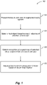
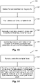
- Fig. 1 shows a method 100 of operation in an augmented reality system employing predictive head tracking, according to one illustrated embodiment.
- the augmented reality system (e.g., a controller subsystem and/or processor thereof) presents a plurality of frames as images to an end user of the augmented reality system.
- the frames will typically include pixel information specifying information for producing one or more virtual objects in a field of view.
- the virtual objects may take any of a wide variety of virtual object forms or formats, which may visual represent physical objects or may represented information, data or logical constructions.
- Non-limiting examples of virtual objects may include: a virtual text object, a virtual numeric object, a virtual alphanumeric object, a virtual tag object, a virtual field object, a virtual chart object, a virtual map object, a virtual instrumentation object or a virtual visual representation of a physical object.
- the augmented reality system selects one or more virtual objects based at least on input indicative of attention of the end user.
- the input may be an actual selection by the end user.
- the selection may be made in real time or may have been previously designated by the end user.
- an end user may select a certain set of virtual instruments as being a type of virtual object the end user typically focuses or pays attention to over other objects.
- the input may be inferred from a variety of sources.
- the input may be related to the virtual objects themselves.
- the input may be additionally or alternatively be related to physical objects in a field of view of the end user or in the field of view of a display or projector.
- the input may be additionally or alternatively be related to the end user themselves, for example a position and/or orientation of the end user and/or a portion of end user (e.g., head, eyes), or historical attributes.
- the historical attributes may be end user specific, or more generalized or generic.
- the historical attributes may be indicative of a set of defined end user characteristics. End user characteristics may, for example, include head movement speed, head movement acceleration, and/or relationship between head movement and eye movement (e.g., ratio of one to the other.
- the end user characteristics tracked by historical attributes may even include indications of a tendency of a given end user to pay attention to certain virtual objects. Such may be specified by virtual object type (e.g., text, charts), by recentness of virtual object (e.g., newly appearing objects), movement of a virtual object (e.g., large shifts from image to image, fast or rapidly movement, direction of movement), and/or characteristics of the virtual object (e.g., color, brightness, size).
- virtual object type e.g., text, charts
- recentness of virtual object e.g., newly appearing objects
- movement of a virtual object e.g., large shifts from image to image, fast or rapidly movement, direction of movement
- characteristics of the virtual object e.g., color, brightness, size
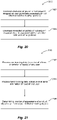
- the augmented reality system determines a location of appearance of a virtual object in a field of view of the end user relative to an end user frame of reference. For example, the augmented reality system may determine a location of a newly introduced virtual object, a virtual object of a defined type, a virtual object moving rapidly or over a large distance, or a virtual object that has historically been a point of attention for the end user.
- the augmented reality system adjusts a presentation of at least one subsequent frame based at least in part on the determined location of appearance of the virtual object in the field of view of the end user.
- Numerous ways of adjusting appearance of the virtual object in the field of view are discussed herein, including non-exhaustively accommodation or compensation, adjusting pixel size, adjusting pixel intensity, adjusting resolution, windowing, and/or blanking or strobing.
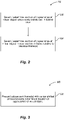
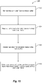
- Fig.2 shows another method 200 of operation in an augmented reality system, according to one illustrated embodiment.
- the method 200 may be employed in executing acts 104 and/or 106 of the method 100 of Fig.1 .
- the method 200 employs techniques that predict head movement based on characteristics of virtual objects that are or will be presented to the end user. For example, anticipating that a newly introduced virtual object or a virtual object who's movement (e.g., due to suddenness, speed, and/or distance) will likely attract the end user's attention, resulting in a head movement to bring the particular virtual object into or proximate a center of the end user's field of view. Additionally, or alternatively the augmented reality system may rely on other characteristics of the virtual objects in assessing which are most likely to attract attention. For example, highly attractive (e.g., flashing, shimmering), large, fast moving, or bright virtual objects may be more likely to attract attention than other virtual objects.
- highly attractive e.g., flashing, shimmering
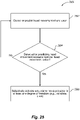
- the augmented reality system selects and/or determines the location of appearance of a virtual object when newly introduced in the field of view of the end user at #AB02.
- a virtual object is considered newly introduced when not appearing in previous (temporally) related frames presented to the end user.
- the augmented reality system relies on the fact that newly introduced virtual objects are like to attract the attention of the end user relative to virtual objects that appear in immediately preceding frames.
- the augmented reality system may rely on other characteristics of the virtual objects in assessing which are most likely to attract attention, for example to select or prioritize among multiple newly introduced virtual objects. For example, highly attractive (e.g., flashing, shimmering), large, fast moving, or bright virtual objects may be more likely to attract attention than other virtual objects.
- the augmented reality system selects and/or determines a location of an appearance of a virtual object in a new position in a frame relative to a position of the same virtual object in at least one previous frame at 204.
- a sudden shifting, a quick shifting, and/or a spatially large shifting of a position of a virtual object from one frame to one or more subsequent frames may be likely to attract the attention or focus of the end user.
- the augmented reality system may rely on other characteristics of the virtual objects in assessing which are most likely to attract attention, for example to select or prioritize among multiple newly introduced virtual objects. For example, highly attractive (e.g., flashing, shimmering), large, or bright virtual objects may be more likely to attract attention than other virtual objects.
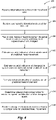
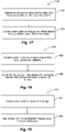
- Fig. 3 shows a method 300 of operation in an augmented reality system, according to one illustrated embodiment.
- the method 300 may be employed in executing act 108 of the method 100 of Fig.1 .
- the augmented reality system presents the at least one subsequent frame with a center of the at least one subsequent frame shifted at least towards, if not centered on, the determined location of appearance of the virtual object in the field of view of the end user.
- the center of the subsequent frame(s) or image(s) may be shifted to be co-located with the location of the selected virtual object that is predicted to attract the end user's attention.
- the center of the subsequent frame(s) may be shifted to be proximate the location of the selected virtual object that is predicted to attract the end user's attention. Such may be performed in two-dimensions or in three-dimensions.
- the two dimensional or three dimensional position of the virtual object may be used to adjust a field of view of subsequent images(s) in two- or three-dimensions, respectively.
- the shifted subsequent frame(s) or image(s) are preferably timed with the predicted head movement of the end user.
- the shifted subsequent frame(s) or image(s) should be presented to the end user as close in timing with the actual head movement as possible. As discussed herein, such may account for speed, acceleration, and variations in speed and acceleration.
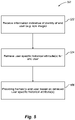
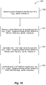
- Fig. 4 shows a method 400 of operation in an augmented reality system, according to one illustrated embodiment.
- the method 400 may be employed in performing the method 100 of Fig. 1 .
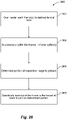
- the augmented reality system receives information indicative of an identity of the end user.
- the information may take any of a large variety of forms.
- the information may be a user name or other user identifier entered by the end user (e.g., keyed) or read from a transponder, magnetic stripe, or machine-readable symbol associated with the end user.
- the information may include biometric information indicative of one or more physical characteristics of the end user.
- the augmented reality system may receive image data that represents a portion (e.g., retina) of one or both eyes of the end user.
- the augmented reality system may project light, for example via one or more optical fibers, into one or both eyes of an end user.
- the light may be modulated, for example to increase a signal to noise ratio and/or limit heating of the eye.
- An image sensor may capture an image of the portion of the eye, for example via the one or more optical fibers that project the light, the optical fiber(s) providing a bi-directional path. Alternatively, a dedicated optical fiber may be employed. As a further alternative an image sensor may be positioned proximate the eye, eliminating the use of the optical fiber(s) as a return path to the image sensor. Certain portions of the human eye (e.g., vasculature of retina) may be considered sufficiently distinctive to serve as a unique end user identifier.
- the augmented reality system retrieves at least one user specific historical attribute for the end user based in the received information indicative of the identity of the end user.
- the user specific historical attribute(s) may be indicative of at least one of: a previous head movement speed for the end user, previous head movement acceleration for the end user, previous eye movement to head movement relationship for the end user, tendencies of end user to pay attention to virtual objects of certain types or with certain characteristics.
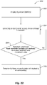
- the augmented reality system (e.g., a controller subsystem and/or processor thereof) predicts an occurrence of a head movement of the end user based at least in part on the determined location of appearance of the virtual object in the field of view of the end user.
- the augmented reality system may rely on an attractiveness of a virtual object in predicting head movements, for example on an end user by end user basis.
- the augmented reality system may employ estimated speed and/or estimated changes in speed or estimated acceleration to at least partially synchronize image presentation with the predicted head movement of the end user.
- the estimated change in the speed in the predicted head movement may be based on a range extending between a first defined time after the start of the predicted head movement and a second defined time before the end of the predicted head movement.
- the augmented reality system estimates at least one value indicative of an estimated speed of the predicted head movement of the end user.
- the augmented reality system may estimate speed based on one or more values, parameters or characteristics. For example, the augmented reality system may rely on a range of movement required to move to the end user's head to a new position to observe the selected or identified virtual object.
- the augmented reality system may rely on average speed for a sampling of humans, or may rely on historical head movement speeds for the particular end user.
- the augmented reality system may rely on historical attributes for the particular end user. Speeds may be represented in angular velocities.
- the augmented reality system estimates at least one change in the speed in the predicted head movement of the end user which occurs over a range of head movement, between a start of the predicted head movement and an end of the predicted head movement.
- the changes in speed may occur at different increments throughout some portion of the predicted range of movement.
- the augmented reality system estimates at least one value indicative of an estimated acceleration of the predicted head movement of the end user.
- the estimated acceleration may be over an entire range of the head movement or over only a portion thereof.
- the estimated acceleration may be over discrete intervals of the range of head movement. Estimates of acceleration may be determined for one or more intervals at some defined duration after the start of head movement. Estimates for acceleration may be determined for one or more intervals at some defined duration before the end of head movement. Estimating spaced from the start and/or end points may avoid large variation in acceleration measurements.
- the augmented reality system determines at least one value that at least partially accommodates or compensates for the estimated speed of the predicted head movement of the end user. For example, the augmented reality system may determine values with respect a total number of frames to present in a given time and/or values that specify where and/or how quickly one or more virtual objects should move across a scene in a series of images to be rendered and/or presented. Such may be used to render subsequent frames.
- the augmented reality system renders the at least one subsequent frame based at least in part on the at least one value that at least partially compensates for the estimated speed of the predicted head movement of the end user.
- the augmented reality system may determine values with respect a total number of frames to present in a given time and/or values that specify where and/or how quickly one or more virtual objects should move across a scene in a series of images to be rendered and/or presented. Such may be used to render subsequent frames.
- the system may be used for predictive head tracking based on a user's historical attributes.
- Fig. 5 shows a method 500 of operation in an augmented reality system employing predictive head tracking, according to one illustrated embodiment.
- the augmented reality system may employ historical attributes in performing predictive head tracking.
- the historical attributes may be end user specific, or more generalized or generic.
- the historical attributes may be indicative of a set of defined end user characteristics. End user characteristics may, for example, include head movement speed, head movement acceleration, and/or relationship between head movement and eye movement (e.g., ratio of one to the other.
- the end user characteristics tracked by historical attributes may even include indications of a tendency of a given end user to pay attention to certain virtual objects.
- the augmented reality system receives information indicative of an identity of the end user.
- the information may take any of a large variety of forms, for example information actively provided be the end user, read from nontransitory storage media, read from the user (e.g., biometric data or characteristics), or inferred from end user actions.
- the augmented reality system retrieves at least one user specific historical attribute for the end user based at least in part on the received information indicative of the identity of the end user.
- the identity information may be received, produced or determined in any of a large variety of ways.
- the augmented reality system provides frames to the end user based at least in part on the retrieved at least one user specific historical attribute for the end user.
- the augmented reality system may provide frames from a frame buffer to a projector or display device (e.g., light source paired with one or more optical fibers), or may render frames to a frame buffer.
- the augmented reality system may provide light via at least one optical fiber which is moveable at least bi-axially.
- the augmented reality system may receive image information indicative of an image of at least a portion of an eye of the end user via the at least an optical fiber which also provides the frames to the end user.
- Fig. 6 shows a method 600 of operation in an augmented reality system employing predictive head tracking, according to one illustrated embodiment.
- the method 600 may be employed in executing act 504 of the method 500 of Fig. 5 .
- the augmented reality system retrieves at least one historical attribute that provides an indication of at least one head movement attribute for the end user.
- the head movement attribute(s) is or are indicative of at least one previous head movement of the end user.
- the historical attributes may be stored in nontransitory media, for example in a database or other logical construct.
- the augmented reality system retrieves at least one historical attribute that provides an indication of head movement speed for at least one previous head movement for the end user.
- the augmented reality system retrieves at least one historical attribute that provides an indication of variation in a head movement speed across at least part of a range of at least one previous head movement by the end user.
- the augmented reality system retrieves at least one historical attribute that provides an indication of head movement acceleration for at least one previous head movement by the end user.
- the augmented reality system retrieves at least one historical attribute that provides an indication of a relationship between head movement and eye movement for at least one previous head and eye movement combination by the end user.
- the relationship may, for example, be represented as a ratio of a head movement value representative of at least one previous head movement and a value representative of at least one previous eye movement by the end user.
- the values may be representative of an amount of movement the head and eyes, respectively, for example represented as an angular change.
- the ratio may be a ratio of historical averages of head movements and historical averages of eye movements by the end user. Additionally or alternatively, other relationships between head and eye movement may be employed, for example speed or acceleration.
- Fig. 7 shows a method 700 of operation in an augmented reality system employing predictive head tracking, according to one illustrated embodiment.
- the method 700 may be employed in executing act 506 of the method 500 of Fig. 5 .
- the augmented reality system predicts at least an end point of a head movement of the end user. For example, where the appearance of a virtual object is used to predict the head movement, the relative location of the particular virtual object may be used as the end point.
- the augmented reality system renders at least one subsequent frame to at least one image buffer.
- the at least one subsequent frame is shifted at least towards, or even all the way to, the predicted end point of the head movement.
- Fig. 8 shows a method 800 of operation in an augmented reality system employing predictive head tracking, according to one illustrated embodiment.
- the method 800 may be employed in executing act 704 of the method 700 of Fig. 7 .
- the augmented reality system renders a plurality of subsequent frames that are shift at least toward the predicted end point of the head movement in at least partial accommodation of at least one head movement attribute for the end user.
- the head movement attributes may be indicative of various physical traits of head movement, particularly historical physical traits of head movement of the end user.
- the head movement attribute(s) may, for example, include one or more of: a historical head movement speed for the end user, a historical head movement acceleration for the end user, and/or a historical relationship (e.g., ratio) between head movement and eye movement for the end user. Shifting may be implemented by rendering subsequent frames with the corresponding image shifted or a center of the corresponding image shifted relative to images corresponding to a previous frame.
- Fig. 9 shows a method 900 of operation in an augmented reality system employing predictive head tracking, according to one illustrated embodiment.
- the method 900 may be employed in executing act 703 of the method 700 of Fig. 7 .
- the augmented reality system predicts an occurrence of a head movement of the end user based at least in part on an appearance of a virtual object in the field of view of the end user.
- the appearance may be an appearance of a new virtual object when newly introduced in the field of view as presented to the end user, temporally, relative to previous frames presented as images to the end user.
- the appearance may be an appearance of a virtual object in a new position in the field of view as presented to the end user, relative to a position of the virtual object as previously presented to the end user.
- the prediction may, for example take into account of factors. For example, the prediction may be based in part on a size or prominence of the virtual object, an amount or percentage of change in position, speed, suddenness acceleration or other change in the position of the virtual object.
- Fig. 10 shows a method 1000 of operation in an augmented reality system, according to one illustrated embodiment.
- the augmented reality system detects an indication that spacing as presented to an end user between some pixels in a frame will differ from the spacing between other pixels in the same frame.
- the augmented reality system may detect an indication that the spacing as presented to the end user between pixels of a first set of pixels in the frame will differ from the spacing as presented to the end user between pixels of at least a second set of pixels in the frame.
- pixels of a frame are sequentially presented (e.g., read out of the frame buffer) over a period of time (e.g., "flying pixel" patterns such as raster scan pattern, spiral scan pattern, Lissajous scan pattern), rapid head movement may cause a variation in pixel spacing between different portions of an image or frame.
- the augmented reality system In response to a detection that the spacing between some pixels in the frame will differ as presented to the end user from the spacing of other pixels in the frame, the augmented reality system provides at least a portion of at least one subsequent frame with at least a first set of pixels adjusted to at least partially compensate at least one pixel characteristic, perceptible by an end user, of the pixels of the first set at 1004. Such may at least partially compensate for a difference in spacing between pixels in different portions of an image as presented to the end user.
- Fig. 11 shows a method 1100 of operation in an augmented reality system, according to one illustrated embodiment.
- the method 1100 may be employed in executing the method 1000 of Fig. 10 .
- the augmented reality system receives signals indicative of an output of at least one head worn inertial sensor worn by the end user.
- the inertial sensors may take a variety of forms, for example gyroscopic sensors or acceleration sensors. Inertial sensors may be single axis or multi-axis devices. The inertial sensors may take the form of MEMS devices.
- the augmented reality system receives signals indicative of an output of at least one head worn imager worn by the end user.
- the imager may, for example, take the form of a digital camera or other image capture device. Such may be a forward facing camera, to capture a field of view that at least approximates a field of view of the end user.
- the augmented reality system detects a head movement exceeding a nominal head movement value.
- the augmented reality system may detect a head movement exceeding a nominal speed and/or a nominal acceleration.
- the augmented reality system may employ signals from the inertial sensors to detect movement, and in particular acceleration.
- the augmented reality system may employ signals from the head mounted camera to detect changes in position of physical objects in the ambient environment, particularly fixed physical objects such as wall, floors, ceilings.
- the augmented reality system may employ any number of image processing techniques.
- the detected change in position allows the augmented reality system to determine a change in position of the head, speed of movement and acceleration.
- the augmented reality system may employ other information in addition or in place of the inertial sensor and head worn imager information.
- the augmented reality system may employ signals from a system that monitors the ambient environment and is not worn by the user, but rather tracks the user.
- a system may employ one or more imager, for instance digital cameras, to monitor the ambient environment.
- the imager(s) detect movement of the end user and parts of the end user such as the head.
- various image processing techniques may be employed.
- Such a system may be advantageously paired with a structured light system.
- the method #CB00 may be executed independently of detected or even predicted head movement.
- the augmented reality system selects a first set of pixels of the frame, for example based on a direction of the detected head movement.
- the augmented reality system may additionally select the first set of pixels of the frame based on other criteria, for example a speed of the detected head movement.
- the augmented reality system adjusts at least one of a size and/or an intensity of at least some of the pixels of the first set of pixels of at least one subsequent frame.
- the adjustment may be designed to at least accommodate or at least partially compensate for undesired variation in the frame or image that result from the head movement.
- the augmented reality system renders the at least one subsequent frame.
- the rendered subsequent frame includes adjusted pixel information to at least partially accommodate or at least partially accommodate or compensate for undesired variation in the frame or image that result from the head movement.
- the augmented reality system reads out the at least one subsequent frame from at least one frame buffer that stores one or more subsequent frames.
- the augmented reality system may selectively read out the at least one subsequent frame from at least one frame buffer.
- Such may take advantage of over rendering where frames are over rendered relative to the size of the image area or field of view.
- the system particularly when head mounted, will in most instances be dedicated to a fixed display surface having a known area and known resolution. This is in contrast to computers and other devices which are intended to supply signals to displays of a wide variety of sizes and resolutions.
- the augmented reality system selectively reads into or out of the frame buffer(s) rather than reading in or reading out the entire frame from the frame buffer.
- Over rendering may prevent running the GPU as excessively as might otherwise be required if a new frame where rendered to create subsequent images to show those portions that are outside of a previous image. For instance, without over rendering, the augmented reality system would need to render a new frame each time the end user's head was moved. With over rendering, a dedicated set of electronics may be employed for selecting or reading out the desired portions of the over rendered frames, essentially moving a window within a previously rendered frame.
- Fig. 12 shows a method 1200 of operation in an augmented reality system, according to one illustrated embodiment.
- the method 1200 may be employed in executing acts 1108 and 1110 of the method 1100 of Fig. 11 .
- the augmented reality system selects at least a first set of pixels of the frame such that the first set of pixels are in a given direction (e.g., same direction, opposite direction) with respect to a direction of a detected head movement.
- a given direction e.g., same direction, opposite direction
- the augmented reality system adjusts a size of pixels of the selected set(s) as presented to the user of the pixels of the first set of pixels of the at least one subsequent frame.
- the augmented reality system may select a first set of pixels of the frame such that the first set of pixels are positioned in a same direction as a direction of the detected head movement, relative to other pixels.
- the first set of pixels may be oriented relatively toward a left in an image relative to a second set of pixels oriented generally to a right in the image.
- the first set of pixels may be oriented relatively toward a top in an image relative to a second set of pixels oriented generally to a bottom in the image.
- the augmented reality system may provide one or more subsequent frames or images where the pixels of the first set have an increased size, relative to some other pixels in the subsequent frame(s). Such can at least partially accommodate or at least partially compensate for a spreading between pixels that may result from rapid head movement which the augmented reality system cannot keep up with.
- the augmented reality system may select a first set of pixels of the frame such that the first set of pixels are positioned in an opposite direction from a direction of the detected head movement, relative to other pixels.
- the augmented reality system may provide one or more subsequent frames or images where the pixels of the first set have a decreased size, relative to some other pixels in the subsequent frame(s). Such can at least partially accommodate or at least partially compensate for a spreading between pixels that may result from rapid head movement which the augmented reality system cannot keep up with.
- Adjusting (e.g., increasing, decreasing) a size of the pixels of selected set(s) may include adjusting a variable focus element. Adjusting (e.g., increasing, decreasing) a size of the pixels of selected set(s) may include adjusting a variable size source. Adjusting (e.g., increasing, decreasing) a size of the pixels of selected set(s) may include adjusting a jitter.
- the augmented reality system may select a first set of pixels of the frame such that the first set of pixels are positioned in a same direction as a direction of the detected head movement relative to other pixels.
- the augmented reality system may provide one or more subsequent frames or images where the pixels of the first set have an increased intensity, relative to some other pixels in the subsequent frame(s). Such can at least partially accommodate or at least partially compensate for a spreading between pixels that may result from rapid head movement which the augmented reality system cannot keep up with.
- the augmented reality system may select a first set of pixels of the frame such that the first set of pixels are positioned in an opposite direction as a direction of the detected head movement.
- the augmented reality system may provide one or more subsequent frames or images where the pixels of the first set have a decreased intensity, relative to some other pixels in the subsequent frame(s). Such can at least partially accommodate or at least partially compensate for a spreading between pixels that may result from rapid head movement which the augmented reality system cannot keep up with.
- the augmented reality system may adjust only the size of the selected pixels, only the intensity of the selected pixels, or both the size and intensity of selected pixels. Further, the augmented reality system may adjust intensity of some pixels, the size of other pixels, the intensity and size of yet even other pixels, and/or not adjust either the intensity or size of yet further pixels.
- Fig. 13 shows a method 00 of operation in an augmented reality system, according to one illustrated embodiment.
- the augmented reality system (e.g., a controller subsystem and/or processor thereof) renders a first complete frame to an image buffer.
- the first complete frame comprises pixel information for sequential presentation of pixels to form an image of a number of virtual objects.
- the first complete frame may take a variety of forms suitable for various display technologies.
- a complete frame may include pixel information suitable for forming a complete raster scan frame, which may be an interlaced raster scan frame with two fields.
- Each field of the interlaced raster scan may include a plurality of lines, a first field comprising the odd lines and a second field comprising the even lines.
- the odd and even lines may be interlaced at least as displayed to the end user.
- a particularly advantageous technology employs spiral scan lines.
- the spiral scan approach may employ a single field per frame, for instance consisting of a single spiral trace.
- the spiral scan approach may employ two or more fields per frame, for instance consisting of two or more spiral traces, presented sequentially.
- the spiral traces may advantageously be interlaced or nested simply by introducing a phase shift between each field of the frame.
- Another technology employs a Lissajous scan approach.
- the Lissajous scan approach may employ a single field per frame, for instance consisting of a single Lissajous trace.
- the Lissajous scan approach may employ two or more fields per frame, for instance consisting of two or more Lissajous traces, presented sequentially.
- the Lissajous traces may advantageously be interlaced or nested simply by introducing a phase shift between each field of the frame.
- the augmented reality system starts a presentation of the first complete frame.
- Such may include reading out of the frame buffer(s), for example to drive a light source(s) and end of one or more optical fibers.
- the reading out may include dynamically determining which portions of the frame buffer to read out.
- the augmented reality system detects a head movement of an end user exceeding a nominal head movement value. Such may employ any of the various approaches previously discussed.
- the augmented reality system dynamically interrupts the presentation of the first complete frame before completion of the presentation of the entire first complete frame.
- the augmented reality system starts presentation of an update to the first complete frame. At least a portion of the pixel information in the update to the complete frame has changed from the first complete frame. For example, in an interlaced raster scan based system, the augmented reality system may present all or part of a first field, replacing the second field with an update second field.
- the augmented reality system may present all or part of a first field (e.g., a first spiral scan line or trace), replacing the second field with an update second field (e.g., an updated second spiral scan line or trace, different from the original second spiral scan or trace).
- a first field e.g., a first spiral scan line or trace
- an update second field e.g., an updated second spiral scan line or trace, different from the original second spiral scan or trace.
- the augmented reality system may present all or part of a first field (e.g., a first Lissajous scan line or trace, i.e., a complete figure 8 cycle), replacing the second field with an update second field (e.g., an updated second Lissajous scan line or trace, different from the original second spiral scan or trace).
- presentation may be interpreted during a presentation of a field, for example during presentation of the first or second, or even a tertiary field. Presentation may be interpreted during presentation of any given line (e.g., row of a raster scan, complete cycle of a spiral or a Lissajous scan).
- Fig. 14 shows a method 1400 of operation in an augmented reality system, according to one illustrated embodiment.
- the method 1400 may be employed in executing the method 1300 of Fig. 13 .
- the augmented reality system (e.g., a controller subsystem and/or processor thereof) renders an updated first complete frame.
- the updated first complete frame includes pixel information that is different in at least one respect from the pixel information of the first complete frame.
- Rendering an updated first complete frame may include rendering the update complete frame with a first field and at least a second field.
- the second field may be interlaced with the first field, typically be presenting sequentially following presentation of the first field.
- the first field may consist of even numbered lines in a raster scan while the second field consists of odd number lines.
- a first field may consist of a first spiral scan line or a first Lissajous scan line, while the second field consists of a second spiral scan line or a second Lissajous scan line.
- rendering an updated first complete frame may include rendering the updated complete frame with a first field and at least a second field, the second field interlaced with at least the first field.
- the augmented reality system presents a portion of the updated first complete frame in lieu of a counterpart portion of the first complete frame.
- a portion of the updated frame is substitute for all or a portion of the first complete frame following the interruption of the original not updated first complete frame.
- the augmented reality system may present a second field of the updated first complete frame in lieu of a second field of the original (i.e., not updated) first complete frame.
- the augmented reality system may present a second portion of a first field along with a second field of the updated first complete frame in lieu of a corresponding portion of a first field and the entire second field of the first original (i.e., not updated) first complete frame.
- the augmented reality system may present a portion (e.g., line, part of line, set of pixels, pixel) of a field of the updated first complete frame in lieu of a counterpart portion of a counterpart field of the first complete frame.
- the augmented reality system may present a portion of a field of the updated first complete frame of a raster scan frame in lieu of a counterpart portion of a counterpart field of the original (i.e., not updated) first complete frame of the raster scan frame.
- the augmented reality system may present a line of the updated first complete frame in lieu of a counterpart line of the original (i.e., not updated) first complete frame.
- the augmented reality system may present a spiral line of the updated first complete frame in lieu of a counter spiral line of the original (i.e., not updated) first complete frame.
- the augmented reality system may present a portion of a line of the updated first complete frame in lieu of a counterpart portion of a counterpart line of the original (i.e., not updated) first complete frame.
- the augmented reality system may present at least one pixel of the updated first complete frame in lieu of a counterpart at least one pixel of the original (i.e., not updated) first complete frame.
- the augmented reality system may present one full cycle of a Lissajous pattern scan of the updated first complete frame in lieu of a counter part one full cycle of a Lissajous pattern scan of the original (i.e., not updated) first complete frame.
- Fig. 15 shows a method 1500 of operation in an augmented reality system, according to one illustrated embodiment.
- the method 1500 may be employed in executing the method 1300 of Fig. 13 .
- the augmented reality system (e.g., a controller subsystem and/or processor thereof) renders a first complete frame to a frame buffer.
- the first complete frame may, for example, include a first field and at least a second field.
- the first field may, for example, include pixel information for at least a first spiral scan line and the second field may include pixel information for at least a second spiral scan line.
- the scan line(s) of the second field may be interlaced with the scan line(s) of the first field.
- the first field may, for example, include pixel information for at least a first Lissajous scan line and the second field may include pixel information for at least a second Lissajous scan line.
- the scan line(s) of the second field may be interlaced with the scan line(s) of the first field. Interlacing of scan lines for both spiral and Lissajous scan patterns may be efficiently achieved with phase shifts.
- the number of fields or scan lines can be greater than two, for example three, four, eight, sixteen or more.
- the augmented reality system starts to read out of the frame buffer, which stores the first complete frame.
- the augmented reality system may drive the light sources and a yoke or other device or structure to generate an image based on the pixel data specified in the frame from the image buffer.
- the augmented reality system renders an updated first complete frame to the frame buffer.
- the updated first complete frame includes pixel information that specifies a frame, a portion of which has changed from the information specified by the original (i.e., not updated) first complete frame
- the augmented reality system starts to read out the updated first complete frame before completion of the reading out of the first complete frame from the frame buffer, thereby interrupting presentation of the original (i.e., not updated) first complete frame.
- Some implementations may take advantage of having two or more frame buffers, allowing rendering to one frame buffer while a frame is being read out of the other frame buffer. Such should not be considered limiting in the various implementations of augmented reality systems may employ one, two, three or even more frame buffers.
- Fig. 16 shows a method 1600 of operation in an augmented reality system, according to one illustrated embodiment.
- the method 1600 may be employed in executing the method 1300 of Fig. 13 .
- the augmented reality system (e.g., a controller subsystem and/or processor thereof) generates pixel information for a first scan line (e.g., spiral, Lissajous).
- a first scan line e.g., spiral, Lissajous
- the augmented reality system generates pixel information for a second scan line (e.g., spiral, Lissajous) phase shifted relative to the first scan line (e.g., spiral, Lissajous).
- Phase shifting advantageously interfaces or nests the second scan line with the first scan line for spiral and Lissajous scan lines.
- the augmented reality system generates pixel information for a third scan line (e.g., spiral, Lissajous) phase shifted relative to the second scan line (e.g., spiral, Lissajous).
- Phase shifting advantageously interfaces or nests the third scan line with the first and the second scan lines for spiral and Lissajous scan lines.
- the augmented reality system generates pixel information for a fourth scan line (e.g., spiral, Lissajous) phase shifted relative to the third scan line (e.g., spiral, Lissajous).
- Phase shifting advantageously interfaces or nests the fourth scan line with the first, the second, and the third scan lines for spiral and Lissajous scan lines.
- Fig. 17 shows a method 1700 of operation in an augmented reality system, according to one illustrated embodiment.
- the augmented reality system determines a respective resolution for each of at least two portions of the respective frame. Portions may be fields, lines, other subdivision, or even individual pixels.
- the augmented reality system causes a presentation of images of virtual objects based on the plurality of frames, at least some of the images having a variable resolution within the image as presented to an end user. For example, spacing between adjacent pixels may differ from one portion to another.
- Fig. 18 shows a method 1800 of operation in an augmented reality system, according to one illustrated embodiment.
- the method 1800 may be employed in executing the method 1700 of Fig. 17 .
- the augmented reality system (e.g., a controller subsystem and/or processor thereof) render frames as respective pixel data for a spiral scan pattern.
- the augmented reality system adjusts the amplitude of a drive signal between the time of presenting a first portion of a first one of the frames and presenting a second portion of the first one of the frames.
- This change in amplitude results in the variable resolution in the image that corresponds to the first one of the frames.
- the augmented reality system may for example vary a slope or ramp of the drive signal. Such is particularly useful where used with a spiral scan pattern. For instance, a first field of a frame may have one slope or ramp which the second field has a different slope or ramp, thereby changing the effective resolution with a single frame.
- the higher resolution or pixel density may be employed at or proximate locations of end user interest or attraction, while lower resolution or pixel density may be used away from such locations.
- the high resolution may appear around the center of an image, while surround portions appear at lower resolutions.
- Such essentially implements what can be denominated a foviated display, with steerable pixels.
- Fig. 19 shows a method 1900 of operation in an augmented reality system, according to one illustrated embodiment.
- the method 1800 may be employed in conjunction or as part of executing the method 1700 of Fig. 17 .
- the augmented reality system assesses a point of attention in a least a first image for the end user.
- the augmented reality system may use any of the previously described techniques for assessing such. For example, determining whether and where a new virtual object will appear, or where a virtual object will move to within a field of view of the end user.
- the augmented reality system may assess a relative attractiveness of the virtual objects (e.g., speed, color, size, brightness, shimmer).
- eye tracking information indicative of a location in a field of view which the eyes of the end user are tracking or focused on.
- Eye tracking information may, for example, be supplied via one or more head worn transducers, for instance head worn cameras. Such eye tracking information may, for example, be discerned by projecting light at the end user's eyes, and detecting the return or reflection of at least some of that projected light. For instance, a projection subsystem that creates or projects the images may project a pixel, dot or other element of light from the at least one optical fiber to create a glint off the end user's cornea. Eye tracking may employ, one, two, three or even more spots or dots of light. The more spots or dots of light, the more information may be discerned.
- the light sources may be pulsed or modulated, for example in synchronization with a frame rate of a camera or image sensor.
- spots or dots may appear as lines as eyes move.
- a direction of the lines as the lines trace across a sensor may indicate a direction of the eye movement.
- Orientation of the lines e.g., vertical, horizontal, diagonal indicates orientation of the eye movement.
- a length of a line is indicative of speed of eye movement.
- the light may be modulated (e.g., temporally, intensity) to increase the signal to noise ratio. Additionally or alternatively, the light may be of a specific wavelength (e.g., near-IR), allowing such to be distinguished from background light or even the light that forms the image that the end user is watching. The light may be modulated to reduce a total amount of energy (e.g., heat) that the augmented reality system is providing to the eye(s).
- the glint may be returned via the same, or another, optical fiber to a sensor.
- the sensor may, for example take the form of a two-dimensional image sensor, for instance a CCD sensor or a CMOS sensor.
- the augmented reality system may detect and track relative movements of the eyes, providing an indication of a point or location of the end user's attention or focus.
- the augmented reality system may logically associate a virtual object or virtual event (e.g., appearance or movement of a virtual object) with the identified point or location of the end user's attention or focus.
- a virtual object or virtual event e.g., appearance or movement of a virtual object
- the augmented reality system may designate a virtual object that appears at or at least proximate the point or location of the end user's attention or focus as an attractive virtual object to the end user.
- the augmented reality system adjusts (e.g., increases, decreases) resolution in at least one portion of at least one subsequent image.
- the augmented reality system may employ any of the various techniques described herein, as well as other techniques to adjust resolution of a portion of a subsequent page relative to other portions of the same subsequent page.
- Fig. 20 shows a method 2000 of operation in an augmented reality system, according to one illustrated embodiment.
- the method 2000 may be employed in executing act 1904 of the method 1900 of Fig. 19 .
- the augmented reality system increases a resolution in a portion of the at least one subsequent image that is at least proximate the assessed point of attention relative to other portions of the at least one subsequent image.
- resolution may be adjusted for spiral scan patterns by controlling a magnitude or amplitude (e.g., current, voltage) of the drive signal.
- the resolution may be adjusted by adjusting a slope of the drive signal. Resolution may thus be increased by increasing the amplitude of the drive signal, while the phase is left unchanged.
- the augmented reality system decreases a resolution in a portion of the at least one subsequent image that is distal to the assessed point of attention relative to other portions of the at least one subsequent image.
- Resolution may be decreased by decreasing the amplitude of the drive signal, while the phase is left unchanged.
- the resolution is only increased, increasing in some portions while neither increasing nor decreasing in other portions. In other implementations the resolution is only decreased, decreasing in some portions while neither increasing nor decreasing in other portions. In yet still other implementations resolution is both increased in some portions while decreased in other portions.
- Fig. 21 shows a method 2100 of operation in an augmented reality system, according to one illustrated embodiment.
- the method 2100 may be employed in conjunction with the method 1700 of Fig. 17 .
- the augmented reality system processes eye tracking data.
- the eye tracking data is indicative of at least an orientation of at least one eye of the end user.
- the eye tracking data is supplied via at least one transducer.
- the eye tracking data may be supplied via a head worn transducer.
- eye tracking data is collected via an optical fiber, with a transducer positioned at or proximate a distal end thereof.
- the optical fiber may collect light reflected from a portion of the end user's eye(s), which may be a glint.
- the optical fiber may be the same optical fiber as used to create the image for display or projection to the end user.
- the augmented reality system processes head tracking data.
- the head tracking data is indicative of at least an orientation of a head of the end user.
- the head tracking data may be supplied via at least one transducer.
- one or more head worn or mounted transducers such as inertial sensors (e.g., gyroscopic sensors, accelerometers).
- Head movement tracking may be implemented using one or more head worn or head mounted light sources and at least one sensor. Head tracking may employ, one, two, three or even more spots or dots of light. The more spots or dots of light, the more information may be discerned.
- the light sources e.g., laser diodes
- the laser source(s) may be modulated at a frequency that is lower than the frame rate of the camera or image sensor. In which case, spots or dots may appear as lines as the head move.
- a direction of the lines as the lines trace across a sensor may indicate a direction of the head movement.
- Orientation of the lines e.g., vertical, horizontal, diagonal
- a length of a line is indicative of speed of head movement.
- Reflected light may also provide information regarding objects in the ambient environment, such as distance and/or geometry (e.g., planar, curved) and/or orientation (e.g., angled or perpendicular).
- one laser bean may produce information regarding direction and velocity (e.g., length of dash or line).
- a second laser beam may add information regarding depth or distance (e.g., Z-axis).
- a third laser beam may add information about the geometry and/or orientation of a surface in the ambient environment. Lasers or other light sources may be pulsed during head movement or during part of the head movement.
- the head tracking data may be supplied via transducers that are not head worn.
- a camera or imager system may image the end user, including the head of the end user, tracking movement thereof.
- Such may, for example, track movement relative to some external reference frame, for instance a reference frame defined by the tracking system or a room in which the tracking system is located.
- the augmented reality system determines a location of appearance of a virtual object in a field of view of the end user relative to an end user frame of reference.
- the appearance may be an appearance of a new virtual object, when newly introduced in a field of view of the end user.
- the appearance may be an appearance of a virtual object in a new position in an image relative to a position of the virtual object in at least one previous image.
- the augmented reality system may employ any of the numerous techniques described elsewhere herein to determine the location of appearance of the virtual object.
- the system may also use blanking to improve end user perception.
- Fig. 22 shows a method 2200 of operation in an augmented reality system, according to one illustrated embodiment.
- the method 2200 effectively employs blanking to improve end user perception experience.
- the augmented reality system (e.g., a controller subsystem and/or processor thereof) displays at least one virtual object to an end user.
- the augmented reality system may render frames to a frame buffer, read out the frames to drive one or more light sources and/or yoke or other system to produce an at least bi-axial movement or trace of the light.
- the augmented reality system detects and/or predicts an occurrence of a head movement of the end user.
- the augmented reality system may employ any of the numerous techniques described elsewhere herein to detect and/or predict an occurrence of a head movement. Without limitation, those techniques include directly sensing head movement, for example via inertial transducers or sensor, or via images from a head worn imager or an environmental imager that images an area in which the end user is present and visible. Those techniques also include indirectly predicting head movement, for instance by determining where a new virtual object will appear, where an existing virtual object will move, or where particularly attractive virtual objects are positioned in the image.
- the augmented reality system assesses whether the detected and/or the predicted head movement exceeds or is predicted to exceed a nominal head movement value.
- the augmented reality system may employ any of the numerous techniques described elsewhere herein to assesses whether the detected and/or the predicted head movement exceeds or is predicted to exceed a nominal head movement value. Such may include simple comparison of detected or predicted speed to a nominal speed. Such may include simple comparison of detected or predicted acceleration to a nominal acceleration. Such may include simple comparison of detected or predicted range to a nominal range. Such may include more complicated comparisons, including averages or integrations of speed, acceleration or range over multiple times during a movement. Such may even employ historical attributes or other information.
- the augmented reality system temporarily blanks at least a portion of the display of the at least one virtual object to the end user. For example, the augmented reality system may stop reading from the frame buffer. Additionally or alternatively, the augmented reality system may turn off an illumination or light source. Such may include temporarily turning off a back light of an LCD display.
- Fig. 23 shows a method 2300 of operation in an augmented reality system, according to one illustrated embodiment.
- the method 2300 may be employed in performing the method 2200 of Fig. 22 .
- the augmented reality system processes head tracking data.
- the head tracking data is indicative of at least an orientation of a head of the end user.
- the head tracking data may be supplied via at least one transducer, which may or may not be head worn by the end user.
- the augmented reality system may employ any of the numerous techniques described elsewhere herein to process the head tracking data.
- the augmented reality system determines a location of appearance of a virtual object in a field of view of the end user relative to an end user frame of reference.
- the determining a location of appearance of a virtual object when newly introduced in a field of view of the end user.
- the augmented reality system may employ any of the numerous techniques described elsewhere herein to determine a location of appearance of a virtual object.
- the augmented reality system assesses whether determined appearance of virtual object is sufficiently attractive. For example, the augmented reality system may assess a relative visual attractiveness of the virtual objects (e.g., speed, color, size, brightness, shimmer, transparency, special optical effects). Also for example, the augmented reality system may assess the relative interest attractiveness (e.g., newness, recentness, previous attention, previous identification by the end user, previous interaction with by the end user).
- a relative visual attractiveness of the virtual objects e.g., speed, color, size, brightness, shimmer, transparency, special optical effects.
- the augmented reality system may assess the relative interest attractiveness (e.g., newness, recentness, previous attention, previous identification by the end user, previous interaction with by the end user).
- the augmented reality system assesses whether the determined location requires the end user to turn the end user's head relative to a current position of the end user's head.
- the augmented reality system may employ a current position and/or orientation of the end user's head and a relative position and/or orientation of the virtual object.
- the augmented reality system may determine a distance, for example angular distance between a current focus of the end user and the position and/or orientation of the virtual object.
- the augmented reality system may determine whether the determined distance is within a range of eye movement, or whether the end user must also turn their head. If the end user must turn their head, the system may assess how far the end user must turn their head.
- the augmented reality system may employ information that specifies a relationship between eye movement and head movement for the end user. Such may indicate to what extent the end user will shift their gaze via eye movements alone, before turning their heads.
- the relationship between eye movement and head movement may be specified for various different directions, for instance a) up to down, b) down to up, c) left to right, d) right to left, e) diagonally from lower left to upper right, f) diagonally from lower right to upper left, g) diagonally from upper left to lower right, or h) diagonally from upper right to lower left.
- the augmented reality system predicting the occurrence of the head movement based on the assessment.
- the augmented reality system may use one or more factors form the assessment in predicting whether head movement will occur, a direction and/or orientation of the head movement, and/or speed or acceleration of the head movement.
- the augmented reality system may employ historical data either end user specific or more generic to a group of end users.
- the augmented reality system may implement one or more machine learning algorithms to increase the accuracy of head movement prediction.
- Fig. 24 shows a method 2400 of operation in an augmented reality system, according to one illustrated embodiment.
- the method 2400 may be employed in performing act 2208 of the method 2200 of Fig. 22 .
- the augmented reality system e.g., a controller subsystem and/or processor thereof
- strobes or flashes a display or a backlight of a display e.g., a controller subsystem and/or processor thereof
- the strobing or flashing occur over all or a portion of the detected head movement or predicted head movement.
- Such may advantageously effectively reduce the perception of inconsistencies in a frame or presentation of virtual objects.
- Such may also effectively increase perceived frame rate.
- Fig. 25 shows a method 2500 of operation in an augmented reality system, according to one illustrated embodiment.
- the augmented reality system detects and/or predicts an occurrence of a head movement of an end user.
- the augmented reality system may process head tracking data indicative of at least an orientation of a head of the end user.
- the augmented reality system may determining a location of appearance of a virtual object in a field of view of the end user relative to an end user frame of reference, assess whether the determined location requires the end user to turn a head of the end user, and predict an occurrence of the head movement based on the assessment.
- the augmented reality system may employ any of the numerous techniques described elsewhere herein to detect and/or predict an occurrence of a head movement.
- the augmented reality system determines whether the detected or the predicted head movement exceeds a nominal head movement value.
- the augmented reality system may employ any of the numerous techniques described elsewhere herein to determine whether the detected or the predicted head movement exceeds a nominal head movement value.
- the augmented reality system selectively activates an actuator to move the projector in at least one degree of freedom.
- Moving the projector may include translating the first optical fiber along at least one axis.
- Moving the projector may include pivoting the first optical fiber about at least one axis.
- Fig. 26 shows a method 2600 of operation in an augmented reality system, according to one illustrated embodiment.
- the augmented reality system may over render frames, producing frames that are much larger than need for a maximum area and maximum resolution of a given display technology.
- the area available for display or projection may be set by the various parameters of the equipment.
- the equipment will set an upper end or maximum resolution.
- An over rendered frame includes pixel information for a set of pixels that exceeds the maximum area of display at the maximum resolution. Such may advantageously allow the augmented reality system to read out only portions of frames (e.g., a portion of each field of the frame, if not interrupted). Such may allow the augmented reality system to shift an image presented to the user.
- the augmented reality system (e.g., a controller subsystem and/or processor thereof) over renders each of a plurality of frames for a defined field of view.
- the augmented reality system e.g., a controller subsystem and/or processor thereof
- the area of the frame may be increase by a percentage of the maximum area, for example increasing the pixel information in either a horizontal, vertical or diagonal direction defined by the frame.
- the augmented reality system successively buffers the over rendered frames in at least one frame buffer.
- the augmented reality system may employ a frame buffer that is larger than the frame size required for the maximum display size at maximum resolution.
- Some implementations employ multiple frame buffers. Such may facilitate interruption of presentation for frames, as described elsewhere herein.
- the augmented reality system determines a portion of a respective image to present.
- the augmented reality system may determine the portion based on any of a variety of factors.
- the factors may be indicative of a location in an image or scene at which the end user is paying attention to, focusing on or has otherwise attracted the attention of the end user. Again various techniques may be employed, including but not limited to eye tracking.
- the factors may be indicative of a location in an image or scene at which the end user is predicted to pay attention to, focus on or will otherwise attract the attention of the end user.
- Virtual objects that are attractive of attention based on the inherent nature of the vertical object may, for example, include a virtual object that visually represents an object or item of concern or suspense to either generalized end users or a specific end user (e.g., imminent threats).
- the augmented reality system selectively reads out of the portion of the over rendered frame from the frame buffer.
- the portion is based at least in part on the determined portion of the respective image to present.
- the portion that is read out may have a center that is shifted to be proximate, or even match or co-align, with the identified location.
- the identified location may, for example, be a location in a previous image or frame that has attracted an end user's attention.
- the identified location may, for example, be a location in a subsequent frame which the augmented reality system has predicted will attract the end user's attention.
- Fig. 27 shows a method 2700 of operation in an augmented reality system, according to one illustrated embodiment.
- the method 2700 may be employed in performing the method 2600 of Fig. 26 .
- the method 2700 may be used to predict a location in a subsequent frame or image which will attract the end user's attention.
- the augmented reality system determines a location of appearance of a virtual object in a field of view of the end user relative to an end user frame of reference.
- the augmented reality system selectively reads out of the frame buffer based at least in part on the determining a location of appearance of a virtual object in a field of view.
- the portion that is read out may have a center that is shifted to be proximate, or even match or co-align, with the identified location.
- the boundaries of the portion that is read out may be shifted to encompass the determined location an immediately surrounding areas, in two- or even three-dimensions.
- the augmented reality system may select a portion (e.g., 80%) of the entire over rendered frame to be read out of the frame buffer for presentation to the end user.
- the augmented reality system may select that portion such that the boundaries are shifted relative to a current location of the end user's attention, for instance in images currently being presented to the end user.
- the augmented reality system may select the boundaries based on a combination of the current location and the predicted location, while setting the boundary such that both locations will be presented to the end user in the subsequently presented image(s).
- Fig. 28 shows a method 2800 of operation in an augmented reality system, according to one illustrated embodiment.
- the method 2800 may be employed in performing the method 2600 of Fig. 26 .
- the method 2800 may be employed to determine a location in an image that has attracted or is predicted to attract the attention of the end user.
- the augmented reality system determines the location of appearance of a new virtual object, when the new virtual is newly introduced in the field of view of the end user.
- the augmented reality system may employ any of the various techniques described herein to identify the introduction of a virtual object, which is new relative to immediately previous frames or images presented to the end user. Thus, even if a virtual object has previously been presented to the end user at some other portion of a presentation, the virtual object may be identified as newly introduced if a sufficient number of intervening images have been presented to make the reintroduction of the virtual object attract the attention of the end user.
- the augmented reality system determines the location of appearance of the virtual object in a new position in the frame relative to a position in at least one previous frame.
- the augmented reality system may employ any of the various techniques described herein to identify the moving of a virtual object to a new or different position in a number of images, which is move relative to immediately previous frames or images presented to the end user.
- the virtual object may be identified as moved or moving if a sufficient number of intervening images have been presented to make the reappearance of the virtual object at the previous location attract the attention of the end user.
- the augmented reality system determines a location of a virtual object having at least a defined minimum speed in a field of view of the end user.
- the augmented reality system may employ any of the various techniques described herein to determine speed of movement of a virtual object from image to image and to compare that speed to a defined or nominal speed.
- the determined speed may be relative to a fixed reference frame in the image or relative to other virtual objects and/or physical objects that appear in the image.
- the augmented reality system determines a portion of a respective image to present based at least in part on a location of the virtual object in an image.
- the augmented reality system may employ any of the various techniques described herein to determine the portion of a respective image to present. The determination may be based on any of a variety of factors.
- the factors may, for example, include factors or data that is indicative of a location in an image or scene at which the end user is paying attention to, focusing on or has otherwise attracted the attention of the end user.
- the factors may, for example, include factors or data that is indicative of a location in an image or scene at which the end user is predicted to pay attention to, focus on or will otherwise attract the attention of the end user.
- the augmented reality system may employ any of the various techniques described elsewhere herein for identifying locations that have attracted the end user's attention, whether via actual detection or via prediction.
- the augmented reality system reads out a portion of the frame buffer for at least one subsequent frame.
- the portion that is read out shifts a center of the image at least toward the determined portion of the respective image that will be presented.
- the augmented reality system may employ any of the various techniques described herein to read out of the frame buffer a portion of a frame that shifts the center or boundaries of the image based on the location of an end user's actual or predicted center of attention.
- Fig. 29 shows a method 2900 of operation in an augmented reality system, according to one illustrated embodiment.
- the method 2900 may be employed in performing the method 2600 of Fig. 26 .
- the method 2900 may be employed to determine a which portion of a frame to read out based on a predicted head movement of the end user.
- the augmented reality system (e.g., a controller subsystem and/or processor thereof) predicts an occurrence of a head movement of the end user.
- the augmented reality system may employ any of the various techniques described herein to predict head movement. Such techniques include, but are not limited to, detecting the appearance in images of a new virtual object, a moving virtual object, a virtual objecting moving rapidly, a previously selected virtual object and/or a visually attractive virtual object.
- the augmented reality system determines a portion of a respective frame or image to present based at least in part on the predicted head movement.
- the augmented reality system may employ any of the various techniques described herein to determine the portion of the frame to be used. For example, the augmented reality system may select the portion such that the boundaries encompass the location of a predicted end point of the predicted head movement. Where the head movement prediction is predicated on the appearance of a virtual object (e.g., newly introduced, moving, attractive appearance, previously selected by end user), the end point may be coincident with the location of that virtual object in a subsequent frame or image.
- Fig. 30 shows a method 3000 of operation in an augmented reality system, according to one illustrated embodiment.
- the augmented reality system may over render frames, producing frames that are much larger than need for a maximum area and maximum resolution of a given display technology.
- the area available for display or projection may be set by the various parameters of the equipment.
- the equipment will set an upper end or maximum resolution.
- An over rendered frame includes pixel information for a set of pixels that exceeds the maximum area of display at the maximum resolution. Such may advantageously allow the augmented reality system to read out only portions of frames (e.g., a portion of each field of the frame, if not interrupted). Such may allow the augmented reality system to shift an image presented to the user.
- the augmented reality system (e.g., a controller subsystem and/or processor thereof) over renders each of a plurality of frames for a defined field of view.
- the area of the frame may be increase by a percentage of the maximum area, for example increasing the pixel information in either a horizontal, vertical or diagonal direction defined by the frame.
- the augmented reality system determines a portion of a respective image to present.
- the augmented reality system may determine the portion based on any of a variety of factors.
- the factors may be indicative of a location in an image or scene at which the end user is paying attention to, focusing on or has otherwise attracted the attention of the end user. Again various techniques may be employed, including but not limited to eye tracking.
- the factors may be indicative of a location in an image or scene at which the end user is predicted to pay attention to, focus on or will otherwise attract the attention of the end user.
- Virtual objects that are attractive of attention based on the inherent nature of the vertical object may, for example, include a virtual object that visually represents an object or item of concern or suspense to either generalized end users or a specific end user (e.g., imminent threats).
- the augmented reality system dynamically addresses one or more determined portions of the over rendered frame into the buffer(s).
- the determined portion(s) may, for example, have a center that is shifted to be proximate, or even match or co-align, with an identified location of an end user's attraction, interest or focus.
- the identified location may, for example, be a location in a previous image or frame that has attracted an end user's attention.
- the identified location may, for example, be a location in a subsequent frame which the augmented reality system has predicted will attract the end user's attention.
- Some implementations employ multiple frame buffers. Such may facilitate interruption of presentation for frames, as described elsewhere herein.
- the augmented reality system reads out of the determined portion(s) of the over rendered frame from the frame buffer.
- the invention includes methods that may be performed using the subject devices.
- the methods may comprise the act of providing such a suitable device. Such provision may be performed by the end user.
- the "providing" act merely requires the end user obtain, access, approach, position, set-up, activate, power-up or otherwise act to provide the requisite device in the subject method.
- Methods recited herein may be carried out in any order of the recited events which is logically possible, as well as in the recited order of events.
- any optional feature of the inventive variations described may be set forth and claimed independently, or in combination with any one or more of the features described herein.
- Reference to a singular item includes the possibility that there are plural of the same items present. More specifically, as used herein and in claims associated hereto, the singular forms “a,” “an,” “said,” and “the” include plural referents unless the specifically stated otherwise.
- use of the articles allow for "at least one" of the subject item in the description above as well as claims associated with this disclosure.
- claims may be drafted to exclude any optional element. As such, this statement is intended to serve as antecedent basis for use of such exclusive terminology as “solely,” “only” and the like in connection with the recitation of claim elements, or use of a “negative” limitation.
Landscapes
- Engineering & Computer Science (AREA)
- Physics & Mathematics (AREA)
- Theoretical Computer Science (AREA)
- General Physics & Mathematics (AREA)
- General Engineering & Computer Science (AREA)
- Human Computer Interaction (AREA)
- Optics & Photonics (AREA)
- Computer Hardware Design (AREA)
- Software Systems (AREA)
- Computer Graphics (AREA)
- Computer Vision & Pattern Recognition (AREA)
- Controls And Circuits For Display Device (AREA)
- User Interface Of Digital Computer (AREA)
- Processing Or Creating Images (AREA)
- Testing, Inspecting, Measuring Of Stereoscopic Televisions And Televisions (AREA)
- Image Generation (AREA)
- Studio Devices (AREA)
- Transforming Electric Information Into Light Information (AREA)
- Control Of Indicators Other Than Cathode Ray Tubes (AREA)
- Selective Calling Equipment (AREA)
- Closed-Circuit Television Systems (AREA)
Applications Claiming Priority (3)
| Application Number | Priority Date | Filing Date | Title |
|---|---|---|---|
| US201361801219P | 2013-03-15 | 2013-03-15 | |
| EP14764114.6A EP2973532A4 (en) | 2013-03-15 | 2014-03-14 | Display system and method |
| PCT/US2014/028977 WO2014144526A2 (en) | 2013-03-15 | 2014-03-14 | Display system and method |
Related Parent Applications (1)
| Application Number | Title | Priority Date | Filing Date |
|---|---|---|---|
| EP14764114.6A Division EP2973532A4 (en) | 2013-03-15 | 2014-03-14 | Display system and method |
Publications (1)
| Publication Number | Publication Date |
|---|---|
| EP4027222A1 true EP4027222A1 (en) | 2022-07-13 |
Family
ID=51525486
Family Applications (2)
| Application Number | Title | Priority Date | Filing Date |
|---|---|---|---|
| EP22158760.3A Pending EP4027222A1 (en) | 2013-03-15 | 2014-03-14 | Display system and method |
| EP14764114.6A Ceased EP2973532A4 (en) | 2013-03-15 | 2014-03-14 | Display system and method |
Family Applications After (1)
| Application Number | Title | Priority Date | Filing Date |
|---|---|---|---|
| EP14764114.6A Ceased EP2973532A4 (en) | 2013-03-15 | 2014-03-14 | Display system and method |
Country Status (10)
| Country | Link |
|---|---|
| US (12) | US9417452B2 (https=) |
| EP (2) | EP4027222A1 (https=) |
| JP (10) | JP6326482B2 (https=) |
| KR (8) | KR102318391B1 (https=) |
| CN (9) | CN108427504B (https=) |
| AU (8) | AU2014229004B2 (https=) |
| CA (2) | CA2905506C (https=) |
| IL (8) | IL241657B (https=) |
| NZ (8) | NZ735751A (https=) |
| WO (1) | WO2014144526A2 (https=) |
Families Citing this family (595)
| Publication number | Priority date | Publication date | Assignee | Title |
|---|---|---|---|---|
| GB0522968D0 (en) | 2005-11-11 | 2005-12-21 | Popovich Milan M | Holographic illumination device |
| GB0718706D0 (en) | 2007-09-25 | 2007-11-07 | Creative Physics Ltd | Method and apparatus for reducing laser speckle |
| US9335604B2 (en) | 2013-12-11 | 2016-05-10 | Milan Momcilo Popovich | Holographic waveguide display |
| US11726332B2 (en) | 2009-04-27 | 2023-08-15 | Digilens Inc. | Diffractive projection apparatus |
| WO2011042711A2 (en) | 2009-10-09 | 2011-04-14 | Milan Momcilo Popovich | Compact edge illuminated diffractive display |
| US11204540B2 (en) | 2009-10-09 | 2021-12-21 | Digilens Inc. | Diffractive waveguide providing a retinal image |
| WO2012136970A1 (en) | 2011-04-07 | 2012-10-11 | Milan Momcilo Popovich | Laser despeckler based on angular diversity |
| WO2016020630A2 (en) | 2014-08-08 | 2016-02-11 | Milan Momcilo Popovich | Waveguide laser illuminator incorporating a despeckler |
| US10670876B2 (en) | 2011-08-24 | 2020-06-02 | Digilens Inc. | Waveguide laser illuminator incorporating a despeckler |
| EP2748670B1 (en) | 2011-08-24 | 2015-11-18 | Rockwell Collins, Inc. | Wearable data display |
| WO2013102759A2 (en) | 2012-01-06 | 2013-07-11 | Milan Momcilo Popovich | Contact image sensor using switchable bragg gratings |
| CN103562802B (zh) | 2012-04-25 | 2016-08-17 | 罗克韦尔柯林斯公司 | 全息广角显示器 |
| US9456744B2 (en) | 2012-05-11 | 2016-10-04 | Digilens, Inc. | Apparatus for eye tracking |
| US20160292924A1 (en) * | 2012-10-31 | 2016-10-06 | Sulon Technologies Inc. | System and method for augmented reality and virtual reality applications |
| US9933684B2 (en) * | 2012-11-16 | 2018-04-03 | Rockwell Collins, Inc. | Transparent waveguide display providing upper and lower fields of view having a specific light output aperture configuration |
| IL308285B2 (en) | 2013-03-11 | 2024-11-01 | Magic Leap Inc | System and method for augmentation and virtual reality |
| US9417452B2 (en) | 2013-03-15 | 2016-08-16 | Magic Leap, Inc. | Display system and method |
| WO2014188149A1 (en) | 2013-05-20 | 2014-11-27 | Milan Momcilo Popovich | Holographic waveguide eye tracker |
| US10262462B2 (en) | 2014-04-18 | 2019-04-16 | Magic Leap, Inc. | Systems and methods for augmented and virtual reality |
| US9874749B2 (en) | 2013-11-27 | 2018-01-23 | Magic Leap, Inc. | Virtual and augmented reality systems and methods |
| CN103353667B (zh) | 2013-06-28 | 2015-10-21 | 北京智谷睿拓技术服务有限公司 | 成像调整设备及方法 |
| CN103353677B (zh) | 2013-06-28 | 2015-03-11 | 北京智谷睿拓技术服务有限公司 | 成像装置及方法 |
| CN103353663B (zh) | 2013-06-28 | 2016-08-10 | 北京智谷睿拓技术服务有限公司 | 成像调整装置及方法 |
| WO2015015138A1 (en) | 2013-07-31 | 2015-02-05 | Milan Momcilo Popovich | Method and apparatus for contact image sensing |
| CN103431840B (zh) | 2013-07-31 | 2016-01-20 | 北京智谷睿拓技术服务有限公司 | 眼睛光学参数检测系统及方法 |
| CN103424891B (zh) | 2013-07-31 | 2014-12-17 | 北京智谷睿拓技术服务有限公司 | 成像装置及方法 |
| CN103431980A (zh) | 2013-08-22 | 2013-12-11 | 北京智谷睿拓技术服务有限公司 | 视力保护成像系统及方法 |
| CN103439801B (zh) | 2013-08-22 | 2016-10-26 | 北京智谷睿拓技术服务有限公司 | 视力保护成像装置及方法 |
| CN103605208B (zh) | 2013-08-30 | 2016-09-28 | 北京智谷睿拓技术服务有限公司 | 内容投射系统及方法 |
| CN103500331B (zh) | 2013-08-30 | 2017-11-10 | 北京智谷睿拓技术服务有限公司 | 提醒方法及装置 |
| US10686972B2 (en) | 2013-09-03 | 2020-06-16 | Tobii Ab | Gaze assisted field of view control |
| US10310597B2 (en) * | 2013-09-03 | 2019-06-04 | Tobii Ab | Portable eye tracking device |
| CN105682539B (zh) | 2013-09-03 | 2018-03-16 | 托比股份公司 | 便携式眼睛追踪设备 |
| CN103558909B (zh) * | 2013-10-10 | 2017-03-29 | 北京智谷睿拓技术服务有限公司 | 交互投射显示方法及交互投射显示系统 |
| US9491365B2 (en) * | 2013-11-18 | 2016-11-08 | Intel Corporation | Viewfinder wearable, at least in part, by human operator |
| KR102177133B1 (ko) | 2014-01-31 | 2020-11-10 | 매직 립, 인코포레이티드 | 멀티-포컬 디스플레이 시스템 및 방법 |
| US10203762B2 (en) | 2014-03-11 | 2019-02-12 | Magic Leap, Inc. | Methods and systems for creating virtual and augmented reality |
| US10430985B2 (en) | 2014-03-14 | 2019-10-01 | Magic Leap, Inc. | Augmented reality systems and methods utilizing reflections |
| US11138793B2 (en) | 2014-03-14 | 2021-10-05 | Magic Leap, Inc. | Multi-depth plane display system with reduced switching between depth planes |
| US9547412B1 (en) * | 2014-03-31 | 2017-01-17 | Amazon Technologies, Inc. | User interface configuration to avoid undesired movement effects |
| US10852838B2 (en) | 2014-06-14 | 2020-12-01 | Magic Leap, Inc. | Methods and systems for creating virtual and augmented reality |
| US20150379772A1 (en) * | 2014-06-30 | 2015-12-31 | Samsung Display Co., Ltd. | Tracking accelerator for virtual and augmented reality displays |
| US10540907B2 (en) | 2014-07-31 | 2020-01-21 | Intelligent Technologies International, Inc. | Biometric identification headpiece system for test taking |
| WO2016020632A1 (en) | 2014-08-08 | 2016-02-11 | Milan Momcilo Popovich | Method for holographic mastering and replication |
| US10410535B2 (en) | 2014-08-22 | 2019-09-10 | Intelligent Technologies International, Inc. | Secure testing device |
| CN106662746B (zh) | 2014-08-22 | 2020-10-23 | 国际智能技术公司 | 安全考试设备、系统和方法 |
| US10241330B2 (en) | 2014-09-19 | 2019-03-26 | Digilens, Inc. | Method and apparatus for generating input images for holographic waveguide displays |
| KR101728408B1 (ko) * | 2014-09-22 | 2017-04-19 | (주)에프엑스기어 | 방향 예측을 이용한 저 레이턴시 시뮬레이션 장치 및 방법과, 이를 위한 컴퓨터 프로그램 |
| WO2016046514A1 (en) | 2014-09-26 | 2016-03-31 | LOKOVIC, Kimberly, Sun | Holographic waveguide opticaltracker |
| CA3168318A1 (en) | 2014-09-29 | 2016-04-07 | Magic Leap, Inc. | Architectures and methods for outputting different wavelength light out of waveguides |
| WO2016073202A1 (en) | 2014-11-04 | 2016-05-12 | Intelligent Technologies International, Inc. | Smartcard |
| US9804669B2 (en) * | 2014-11-07 | 2017-10-31 | Eye Labs, Inc. | High resolution perception of content in a wide field of view of a head-mounted display |
| JP6501501B2 (ja) * | 2014-11-12 | 2019-04-17 | キヤノン株式会社 | 情報処理装置、情報処理方法、情報処理システム及びプログラム |
| US10176639B2 (en) | 2014-11-27 | 2019-01-08 | Magic Leap, Inc. | Virtual/augmented reality system having dynamic region resolution |
| JP6555279B2 (ja) * | 2014-12-15 | 2019-08-07 | 株式会社島津製作所 | ヘッドマウントディスプレイ用の動画像処理装置、ヘッドマウントディスプレイ用の動画像処理方法およびヘッドマウントディスプレイシステム |
| US9576399B2 (en) | 2014-12-23 | 2017-02-21 | Meta Company | Apparatuses, methods and systems coupling visual accommodation and visual convergence to the same plane at any depth of an object of interest |
| US10255713B2 (en) | 2014-12-29 | 2019-04-09 | Google Llc | System and method for dynamically adjusting rendering parameters based on user movements |
| US10154239B2 (en) | 2014-12-30 | 2018-12-11 | Onpoint Medical, Inc. | Image-guided surgery with surface reconstruction and augmented reality visualization |
| US9824498B2 (en) * | 2014-12-30 | 2017-11-21 | Sony Interactive Entertainment Inc. | Scanning display system in head-mounted display for virtual reality |
| EP3245551B1 (en) | 2015-01-12 | 2019-09-18 | DigiLens Inc. | Waveguide light field displays |
| WO2016113534A1 (en) | 2015-01-12 | 2016-07-21 | Milan Momcilo Popovich | Environmentally isolated waveguide display |
| WO2016116733A1 (en) | 2015-01-20 | 2016-07-28 | Milan Momcilo Popovich | Holographic waveguide lidar |
| US9632226B2 (en) | 2015-02-12 | 2017-04-25 | Digilens Inc. | Waveguide grating device |
| AU2016225963B2 (en) | 2015-03-05 | 2021-05-13 | Magic Leap, Inc. | Systems and methods for augmented reality |
| US10180734B2 (en) | 2015-03-05 | 2019-01-15 | Magic Leap, Inc. | Systems and methods for augmented reality |
| US10838207B2 (en) * | 2015-03-05 | 2020-11-17 | Magic Leap, Inc. | Systems and methods for augmented reality |
| US20160267714A1 (en) * | 2015-03-12 | 2016-09-15 | LAFORGE Optical, Inc. | Apparatus and Method for Mutli-Layered Graphical User Interface for Use in Mediated Reality |
| US10459145B2 (en) | 2015-03-16 | 2019-10-29 | Digilens Inc. | Waveguide device incorporating a light pipe |
| NZ773818A (en) | 2015-03-16 | 2022-07-29 | Magic Leap Inc | Methods and systems for diagnosing and treating health ailments |
| US10591756B2 (en) | 2015-03-31 | 2020-03-17 | Digilens Inc. | Method and apparatus for contact image sensing |
| US10152906B2 (en) | 2015-04-26 | 2018-12-11 | Mems Start, Llc | Near-eye display system and method |
| CN107924085B (zh) | 2015-06-15 | 2022-09-02 | 奇跃公司 | 虚拟和增强现实系统以及方法 |
| AU2016288213B2 (en) * | 2015-06-30 | 2021-06-24 | Magic Leap, Inc. | Technique for more efficiently displaying text in virtual image generation system |
| US10492981B1 (en) | 2015-07-17 | 2019-12-03 | Bao Tran | Systems and methods for computer assisted operation |
| US10335572B1 (en) | 2015-07-17 | 2019-07-02 | Naveen Kumar | Systems and methods for computer assisted operation |
| US10176642B2 (en) | 2015-07-17 | 2019-01-08 | Bao Tran | Systems and methods for computer assisted operation |
| US10685488B1 (en) | 2015-07-17 | 2020-06-16 | Naveen Kumar | Systems and methods for computer assisted operation |
| US10149958B1 (en) | 2015-07-17 | 2018-12-11 | Bao Tran | Systems and methods for computer assisted operation |
| NZ739054A (en) * | 2015-07-17 | 2020-05-29 | Magic Leap Inc | Virtual/augmented reality system having dynamic region resolution |
| WO2017015302A1 (en) | 2015-07-20 | 2017-01-26 | Magic Leap, Inc. | Collimating fiber scanner design with inward pointing angles in virtual/augmented reality system |
| CN114998557A (zh) | 2015-08-18 | 2022-09-02 | 奇跃公司 | 虚拟和增强现实系统和方法 |
| EP3337383B1 (en) | 2015-08-21 | 2024-10-16 | Magic Leap, Inc. | Eyelid shape estimation |
| KR102591552B1 (ko) | 2015-08-21 | 2023-10-18 | 매직 립, 인코포레이티드 | 눈 포즈 측정을 사용한 눈꺼풀 형상 추정 |
| CN108351700B (zh) | 2015-09-16 | 2022-08-12 | 奇跃公司 | 音频文件的头部姿势混合 |
| HK1256792A1 (zh) | 2015-09-23 | 2019-10-04 | Magic Leap, Inc. | 采用离轴成像器的眼睛成像 |
| CN113759555B (zh) | 2015-10-05 | 2024-09-20 | 迪吉伦斯公司 | 波导显示器 |
| AU2016333970B2 (en) | 2015-10-05 | 2021-08-05 | Magic Leap, Inc. | Microlens collimator for scanning optical fiber in virtual/augmented reality system |
| KR102748808B1 (ko) | 2015-10-06 | 2024-12-30 | 매직 립, 인코포레이티드 | 역각 회절 격자를 가진 가상/증강 현실 시스템 |
| WO2017066346A1 (en) * | 2015-10-12 | 2017-04-20 | Cinova Media | Method and apparatus for optimizing video streaming for virtual reality |
| EP3761232B1 (en) | 2015-10-16 | 2025-12-03 | Magic Leap, Inc. | Eye pose identification using eye features |
| US10088685B1 (en) | 2015-10-19 | 2018-10-02 | Meta Company | Apparatuses, methods and systems for multiple focal distance display |
| KR102701209B1 (ko) | 2015-10-20 | 2024-08-29 | 매직 립, 인코포레이티드 | 3차원 공간에서 가상 객체들 선택 |
| US10466780B1 (en) * | 2015-10-26 | 2019-11-05 | Pillantas | Systems and methods for eye tracking calibration, eye vergence gestures for interface control, and visual aids therefor |
| US10962780B2 (en) * | 2015-10-26 | 2021-03-30 | Microsoft Technology Licensing, Llc | Remote rendering for virtual images |
| CN106652004A (zh) * | 2015-10-30 | 2017-05-10 | 北京锤子数码科技有限公司 | 基于头戴式可视设备对虚拟现实进行渲染的方法及装置 |
| JP6983773B2 (ja) | 2015-11-04 | 2021-12-17 | マジック リープ, インコーポレイテッドMagic Leap, Inc. | 眼追跡に基づく動的ディスプレイ較正 |
| US11231544B2 (en) | 2015-11-06 | 2022-01-25 | Magic Leap, Inc. | Metasurfaces for redirecting light and methods for fabricating |
| US10043075B2 (en) * | 2015-11-19 | 2018-08-07 | Microsoft Technology Licensing, Llc | Eye feature identification |
| JP6511386B2 (ja) | 2015-11-20 | 2019-05-15 | 株式会社ソニー・インタラクティブエンタテインメント | 情報処理装置および画像生成方法 |
| WO2017096241A1 (en) * | 2015-12-02 | 2017-06-08 | Augmenteum, Inc. | System for and method of projecting augmentation imagery in a head-mounted display |
| US10909711B2 (en) | 2015-12-04 | 2021-02-02 | Magic Leap, Inc. | Relocalization systems and methods |
| EP3338166A1 (en) * | 2015-12-22 | 2018-06-27 | Google LLC | System and method for performing electronic display stabilization via retained lightfield rendering |
| US20170188021A1 (en) * | 2015-12-24 | 2017-06-29 | Meta Company | Optical engine for creating wide-field of view fovea-based display |
| US10678958B2 (en) | 2015-12-28 | 2020-06-09 | Intelligent Technologies International, Inc. | Intrusion-protected memory component |
| WO2017120271A1 (en) | 2016-01-04 | 2017-07-13 | Meta Company | Apparatuses, methods and systems for application of forces within a 3d virtual environment |
| US10466480B2 (en) | 2016-01-07 | 2019-11-05 | Magic Leap, Inc. | Virtual and augmented reality systems and methods having unequal numbers of component color images distributed across depth planes |
| JP6845982B2 (ja) * | 2016-01-13 | 2021-03-24 | フォーブ インコーポレーテッド | 表情認識システム、表情認識方法及び表情認識プログラム |
| JP6952713B2 (ja) | 2016-01-19 | 2021-10-20 | マジック リープ, インコーポレイテッドMagic Leap,Inc. | 反射を利用する拡張現実システムおよび方法 |
| US11209898B2 (en) | 2016-01-19 | 2021-12-28 | Magic Leap, Inc. | Eye image collection |
| AU2017209171B2 (en) | 2016-01-20 | 2021-10-21 | Magic Leap, Inc. | Polarizing maintaining optical fiber in virtual/augmented reality system |
| WO2017132050A1 (en) | 2016-01-29 | 2017-08-03 | Magic Leap, Inc. | Display for three-dimensional image |
| US10983340B2 (en) | 2016-02-04 | 2021-04-20 | Digilens Inc. | Holographic waveguide optical tracker |
| US10317991B2 (en) * | 2016-02-09 | 2019-06-11 | Google Llc | Pixel adjusting at display controller for electronic display stabilization |
| IL302656B2 (en) | 2016-02-11 | 2024-10-01 | Magic Leap Inc | Multi-depth plane display system with reduced switching between depth planes |
| WO2017142977A1 (en) | 2016-02-15 | 2017-08-24 | Meta Company | Apparatuses, methods and systems for tethering 3-d virtual elements to digital content |
| JP6991981B2 (ja) | 2016-02-24 | 2022-01-13 | マジック リープ, インコーポレイテッド | 光エミッタのための薄型相互接続子 |
| CA3014496A1 (en) | 2016-02-24 | 2017-08-31 | Magic Leap, Inc. | Polarizing beam splitter with low light leakage |
| IL261148B2 (en) | 2016-02-26 | 2023-12-01 | Magic Leap Inc | Light output system with reflector and lens for highly spatially uniform light output |
| IL295839A (en) | 2016-02-26 | 2022-10-01 | Magic Leap Inc | Display system having a plurality of light pipes for a plurality of light emitters |
| US9939635B2 (en) | 2016-02-29 | 2018-04-10 | Brillio LLC | Method for providing notification in virtual reality device |
| US10571693B2 (en) | 2016-03-01 | 2020-02-25 | Magic Leap, Inc. | Reflective switching device for inputting different wavelengths of light into waveguides |
| CN114690881A (zh) | 2016-03-04 | 2022-07-01 | 奇跃公司 | 减少用电的显示系统以及用于减少显示系统的用电的方法 |
| US10127369B2 (en) | 2016-03-07 | 2018-11-13 | Magic Leap, Inc. | Blue light adjustment for biometric security |
| CN111329551B (zh) | 2016-03-12 | 2025-09-23 | P·K·朗 | 用于脊柱和关节手术的增强现实引导 |
| EP3432780A4 (en) | 2016-03-21 | 2019-10-23 | Washington University | VISUALIZATION THROUGH VIRTUAL REALITY OR EXTENDED REALITY OF MEDICAL 3D IMAGES |
| NZ746117A (en) | 2016-03-22 | 2020-02-28 | Magic Leap Inc | Head mounted display system configured to exchange biometric information |
| CN108780224B (zh) | 2016-03-24 | 2021-08-03 | 迪吉伦斯公司 | 用于提供偏振选择性全息波导装置的方法和设备 |
| KR20180122726A (ko) | 2016-03-25 | 2018-11-13 | 매직 립, 인코포레이티드 | 가상 및 증강 현실 시스템들 및 방법들 |
| US10359806B2 (en) * | 2016-03-28 | 2019-07-23 | Sony Interactive Entertainment Inc. | Pressure sensing to identify fitness and comfort of virtual reality headset |
| JP2017182247A (ja) * | 2016-03-29 | 2017-10-05 | ソニー株式会社 | 情報処理装置、情報処理方法、およびプログラム |
| WO2017172982A1 (en) | 2016-03-31 | 2017-10-05 | Magic Leap, Inc. | Interactions with 3d virtual objects using poses and multiple-dof controllers |
| KR20220040511A (ko) | 2016-04-08 | 2022-03-30 | 매직 립, 인코포레이티드 | 가변 포커스 렌즈 엘리먼트들을 가진 증강 현실 시스템들 및 방법들 |
| JP6734933B2 (ja) | 2016-04-11 | 2020-08-05 | ディジレンズ インコーポレイテッド | 構造化光投影のためのホログラフィック導波管装置 |
| US10341650B2 (en) | 2016-04-15 | 2019-07-02 | Ati Technologies Ulc | Efficient streaming of virtual reality content |
| IL262279B2 (en) | 2016-04-21 | 2023-04-01 | Magic Leap Inc | A visual aura around the field of vision |
| US10437326B2 (en) | 2016-04-21 | 2019-10-08 | Facebook Technologies, Llc | Backlight modulation for liquid crystal display with eyetracking for virtual reality |
| NZ747815A (en) | 2016-04-26 | 2023-05-26 | Magic Leap Inc | Electromagnetic tracking with augmented reality systems |
| US10046229B2 (en) | 2016-05-02 | 2018-08-14 | Bao Tran | Smart device |
| CN113484944A (zh) | 2016-05-06 | 2021-10-08 | 奇跃公司 | 具有用于重定向光的非对称光栅的超表面及其制造方法 |
| IL289757B2 (en) | 2016-05-09 | 2024-12-01 | Magic Leap Inc | Augmented reality systems and methods for user health analysis |
| KR102450431B1 (ko) | 2016-05-12 | 2022-10-04 | 매직 립, 인코포레이티드 | 이미징 도파관을 통해 분배된 광 조작 |
| US10198874B2 (en) * | 2016-05-13 | 2019-02-05 | Google Llc | Methods and apparatus to align components in virtual reality environments |
| US10365712B2 (en) | 2016-05-17 | 2019-07-30 | Google Llc | Object tracking in a head mounted reference frame in an augmented and/or virtual reality environment |
| WO2017201329A1 (en) | 2016-05-20 | 2017-11-23 | Magic Leap, Inc. | Contextual awareness of user interface menus |
| IL297603A (en) | 2016-06-03 | 2022-12-01 | Magic Leap Inc | Augmented reality identity verification |
| EP3469251B1 (en) | 2016-06-10 | 2021-07-07 | Magic Leap, Inc. | Integrating point source for texture projecting bulb |
| KR102491130B1 (ko) | 2016-06-20 | 2023-01-19 | 매직 립, 인코포레이티드 | 시각적 프로세싱 및 지각 상태들을 포함하는 신경학적 상태들의 평가 및 수정을 위한 증강 현실 디스플레이 시스템 |
| US10366536B2 (en) | 2016-06-28 | 2019-07-30 | Microsoft Technology Licensing, Llc | Infinite far-field depth perception for near-field objects in virtual environments |
| EP3479160B1 (en) | 2016-06-30 | 2024-07-24 | Magic Leap, Inc. | Estimating pose in 3d space |
| US10296792B2 (en) | 2016-07-14 | 2019-05-21 | Magic Leap, Inc. | Iris boundary estimation using cornea curvature |
| KR102648770B1 (ko) | 2016-07-14 | 2024-03-15 | 매직 립, 인코포레이티드 | 홍채 식별을 위한 딥 뉴럴 네트워크 |
| US20190235624A1 (en) * | 2016-07-19 | 2019-08-01 | Supereye, Inc. | Systems and methods for predictive visual rendering |
| EP4418082A3 (en) | 2016-07-21 | 2024-11-13 | Magic Leap, Inc. | Technique for controlling virtual image generation system using emotional states of user |
| KR102723374B1 (ko) | 2016-07-25 | 2024-10-29 | 매직 립, 인코포레이티드 | 광 필드 프로세서 시스템 |
| EP3488283B1 (en) | 2016-07-25 | 2024-02-14 | Magic Leap, Inc. | Head-mounted display system |
| KR102649197B1 (ko) * | 2016-07-29 | 2024-03-20 | 삼성전자주식회사 | 그래픽 객체를 표시하기 위한 전자 장치 및 컴퓨터 판독 가능한 기록 매체 |
| US10491402B2 (en) | 2016-07-29 | 2019-11-26 | Magic Leap, Inc. | Secure exchange of cryptographically signed records |
| US10373592B2 (en) | 2016-08-01 | 2019-08-06 | Facebook Technologies, Llc | Adaptive parameters in image regions based on eye tracking information |
| US10649211B2 (en) | 2016-08-02 | 2020-05-12 | Magic Leap, Inc. | Fixed-distance virtual and augmented reality systems and methods |
| US10345925B2 (en) * | 2016-08-03 | 2019-07-09 | Google Llc | Methods and systems for determining positional data for three-dimensional interactions inside virtual reality environments |
| EP4398566A3 (en) | 2016-08-11 | 2024-10-09 | Magic Leap, Inc. | Automatic placement of a virtual object in a three-dimensional space |
| IL292025B2 (en) | 2016-08-12 | 2023-12-01 | Magic Leap Inc | Word flow annotation |
| WO2018039277A1 (en) | 2016-08-22 | 2018-03-01 | Magic Leap, Inc. | Diffractive eyepiece |
| CN114253400A (zh) | 2016-08-22 | 2022-03-29 | 奇跃公司 | 具有深度学习传感器的增强现实显示装置 |
| AU2017314940B2 (en) | 2016-08-26 | 2021-09-23 | Magic Leap, Inc. | Continuous time warp and binocular time warp for virtual and augmented reality display systems and methods |
| CN106331689B (zh) * | 2016-08-26 | 2018-09-18 | 杭州智屏电子商务有限公司 | Vr视频播放时定位对象方法及vr视频播放时定位对象装置 |
| KR102257181B1 (ko) | 2016-09-13 | 2021-05-27 | 매직 립, 인코포레이티드 | 감각 안경류 |
| JP6799603B2 (ja) * | 2016-09-14 | 2020-12-16 | 株式会社スクウェア・エニックス | 映像表示システム及び映像表示方法、映像表示プログラム |
| CA3037044A1 (en) | 2016-09-21 | 2018-03-29 | Magic Leap, Inc. | Systems and methods for optical systems with exit pupil expander |
| US20180082482A1 (en) * | 2016-09-22 | 2018-03-22 | Apple Inc. | Display system having world and user sensors |
| KR102786412B1 (ko) | 2016-09-22 | 2025-03-25 | 매직 립, 인코포레이티드 | 증강 현실 분광기 |
| US10380950B2 (en) * | 2016-09-23 | 2019-08-13 | Novatek Microelectronics Corp. | Method for reducing motion blur and head mounted display apparatus |
| KR102626257B1 (ko) | 2016-09-26 | 2024-01-16 | 매직 립, 인코포레이티드 | 가상 현실 또는 증강 현실 디스플레이 시스템에서 자기 및 광학 센서들의 교정 |
| EP3519878B1 (en) | 2016-09-28 | 2023-04-19 | Magic Leap, Inc. | Face model capture by a wearable device |
| RU2016138608A (ru) | 2016-09-29 | 2018-03-30 | Мэджик Лип, Инк. | Нейронная сеть для сегментации изображения глаза и оценки качества изображения |
| JP6813670B2 (ja) * | 2016-09-30 | 2021-01-13 | 株式会社ソニー・インタラクティブエンタテインメント | 異なるレンダリング及び音像定位を使用する無線ヘッドマウントディスプレイ |
| IL293688B2 (en) | 2016-10-04 | 2024-02-01 | Magic Leap Inc | Efficient data layouts for convolutional neural networks |
| KR102269065B1 (ko) | 2016-10-05 | 2021-06-24 | 매직 립, 인코포레이티드 | 혼합 현실 교정을 위한 안구주위 테스트 |
| IT201600103076A1 (it) * | 2016-10-13 | 2018-04-13 | Osram Gmbh | Procedimento di rilevazione del c.d. view frustum, sistema e prodotto informatico corrispondenti |
| GB2554914B (en) * | 2016-10-14 | 2022-07-20 | Vr Chitect Ltd | Virtual reality system and method |
| EP3529653B1 (en) | 2016-10-21 | 2024-01-24 | Magic Leap, Inc. | System and method for presenting image content on multiple depth planes by providing multiple intra-pupil parallax views |
| KR102561860B1 (ko) | 2016-10-25 | 2023-08-02 | 삼성전자주식회사 | 전자장치 및 그 제어방법 |
| KR102507383B1 (ko) * | 2016-11-08 | 2023-03-08 | 한국전자통신연구원 | 직사각형 윈도우를 이용한 스테레오 정합 방법 및 스테레오 정합 시스템 |
| KR102217797B1 (ko) | 2016-11-11 | 2021-02-18 | 매직 립, 인코포레이티드 | 전체 얼굴 이미지의 안구주위 및 오디오 합성 |
| KR102610030B1 (ko) | 2016-11-15 | 2023-12-04 | 매직 립, 인코포레이티드 | 큐보이드 검출을 위한 딥 러닝 시스템 |
| JP7037561B2 (ja) | 2016-11-16 | 2022-03-16 | マジック リープ, インコーポレイテッド | ウェアラブルコンポーネントのための熱管理システム |
| IL312713A (en) | 2016-11-18 | 2024-07-01 | Magic Leap Inc | Waveguide light multiplexer using crossed gratings |
| CN110192146B (zh) | 2016-11-18 | 2022-09-23 | 奇跃公司 | 空间可变液晶衍射光栅 |
| JP7019695B2 (ja) | 2016-11-18 | 2022-02-15 | マジック リープ, インコーポレイテッド | 広入射角範囲の光を再指向するための多層液晶回折格子 |
| US11067860B2 (en) | 2016-11-18 | 2021-07-20 | Magic Leap, Inc. | Liquid crystal diffractive devices with nano-scale pattern and methods of manufacturing the same |
| WO2018100906A1 (ja) * | 2016-11-30 | 2018-06-07 | グリー株式会社 | アプリケーション制御プログラム、アプリケーション制御方法及びアプリケーション制御システム |
| US11513350B2 (en) | 2016-12-02 | 2022-11-29 | Digilens Inc. | Waveguide device with uniform output illumination |
| EP4220572B1 (en) | 2016-12-05 | 2025-05-14 | Magic Leap, Inc. | Virtual user input controls in a mixed reality environment |
| US10531220B2 (en) | 2016-12-05 | 2020-01-07 | Magic Leap, Inc. | Distributed audio capturing techniques for virtual reality (VR), augmented reality (AR), and mixed reality (MR) systems |
| WO2018106963A1 (en) | 2016-12-08 | 2018-06-14 | Magic Leap, Inc. | Diffractive devices based on cholesteric liquid crystal |
| GB2557593A (en) * | 2016-12-09 | 2018-06-27 | Sony Interactive Entertainment Inc | Virtual reality |
| IL299220A (en) | 2016-12-13 | 2023-02-01 | Magic Leap Inc | Glasses systems for augmented and virtual reality and methods for supplying polarized light and determining glucose levels |
| CN106888203B (zh) | 2016-12-13 | 2020-03-24 | 阿里巴巴集团控股有限公司 | 基于增强现实的虚拟对象分配方法及装置 |
| KR102497707B1 (ko) | 2016-12-13 | 2023-02-08 | 매직 립, 인코포레이티드 | 검출된 특징들을 사용한 3d 객체 렌더링 |
| IL301448B2 (en) | 2016-12-14 | 2024-08-01 | Magic Leap Inc | Structures of liquid crystals through fine-imprint copying of surface alignment templates |
| KR20180071012A (ko) * | 2016-12-19 | 2018-06-27 | 삼성전자주식회사 | 전자 장치 및 전자 장치 제어 방법 |
| CN114675420A (zh) | 2016-12-22 | 2022-06-28 | 奇跃公司 | 用于操纵来自环境光源的光的系统和方法 |
| US10371896B2 (en) | 2016-12-22 | 2019-08-06 | Magic Leap, Inc. | Color separation in planar waveguides using dichroic filters |
| GB2558284B (en) * | 2016-12-23 | 2021-12-08 | Sony Interactive Entertainment Inc | Virtual reality |
| US10746999B2 (en) | 2016-12-28 | 2020-08-18 | Magic Leap, Inc. | Dual depth exit pupil expander |
| EP3563215A4 (en) | 2016-12-29 | 2020-08-05 | Magic Leap, Inc. | AUTOMATIC CONTROL OF A WEARABLE DISPLAY DEVICE BASED ON EXTERNAL CONDITIONS |
| US10610775B1 (en) | 2017-01-04 | 2020-04-07 | Facebook Technologies, Llc | Actuation for a focus adjusting head mounted display |
| EP4122897A1 (en) | 2017-01-05 | 2023-01-25 | Magic Leap, Inc. | Patterning of high refractive index glasses by plasma etching |
| WO2018129398A1 (en) | 2017-01-05 | 2018-07-12 | Digilens, Inc. | Wearable heads up displays |
| JP7224288B2 (ja) | 2017-01-11 | 2023-02-17 | マジック リープ, インコーポレイテッド | 医療アシスタント |
| WO2018132804A1 (en) | 2017-01-16 | 2018-07-19 | Lang Philipp K | Optical guidance for surgical, medical, and dental procedures |
| CN108320331B (zh) * | 2017-01-17 | 2021-10-22 | 上海掌门科技有限公司 | 一种生成用户场景的增强现实视频信息的方法与设备 |
| US10824888B1 (en) * | 2017-01-19 | 2020-11-03 | State Farm Mutual Automobile Insurance Company | Imaging analysis technology to assess movements of vehicle occupants |
| JP6596452B2 (ja) * | 2017-01-23 | 2019-10-23 | ティフォン インコーポレーテッド | 表示装置、表示方法及びその表示プログラム、並びに、遊興施設 |
| US20180213202A1 (en) * | 2017-01-23 | 2018-07-26 | Jaunt Inc. | Generating a Video Stream from a 360-Degree Video |
| US10812936B2 (en) | 2017-01-23 | 2020-10-20 | Magic Leap, Inc. | Localization determination for mixed reality systems |
| CA3051239C (en) | 2017-01-23 | 2023-12-19 | Magic Leap, Inc. | Eyepiece for virtual, augmented, or mixed reality systems |
| US10841724B1 (en) | 2017-01-24 | 2020-11-17 | Ha Tran | Enhanced hearing system |
| US10242654B2 (en) | 2017-01-25 | 2019-03-26 | Microsoft Technology Licensing, Llc | No miss cache structure for real-time image transformations |
| US9978118B1 (en) | 2017-01-25 | 2018-05-22 | Microsoft Technology Licensing, Llc | No miss cache structure for real-time image transformations with data compression |
| CN110476090B (zh) | 2017-01-27 | 2023-04-25 | 奇跃公司 | 用于超表面的抗反射涂层 |
| KR20240074923A (ko) | 2017-01-27 | 2024-05-28 | 매직 립, 인코포레이티드 | 상이하게 배향된 나노빔들을 갖는 메타표면들에 의해 형성된 회절 격자 |
| US11187909B2 (en) | 2017-01-31 | 2021-11-30 | Microsoft Technology Licensing, Llc | Text rendering by microshifting the display in a head mounted display |
| US10298840B2 (en) | 2017-01-31 | 2019-05-21 | Microsoft Technology Licensing, Llc | Foveated camera for video augmented reality and head mounted display |
| US10354140B2 (en) | 2017-01-31 | 2019-07-16 | Microsoft Technology Licensing, Llc | Video noise reduction for video augmented reality system |
| US10504397B2 (en) | 2017-01-31 | 2019-12-10 | Microsoft Technology Licensing, Llc | Curved narrowband illuminant display for head mounted display |
| US11287292B2 (en) | 2017-02-13 | 2022-03-29 | Lockheed Martin Corporation | Sensor system |
| US11347054B2 (en) | 2017-02-16 | 2022-05-31 | Magic Leap, Inc. | Systems and methods for augmented reality |
| US11481527B2 (en) | 2017-02-22 | 2022-10-25 | Middle Chart, LLC | Apparatus for displaying information about an item of equipment in a direction of interest |
| US11468209B2 (en) | 2017-02-22 | 2022-10-11 | Middle Chart, LLC | Method and apparatus for display of digital content associated with a location in a wireless communications area |
| US12475273B2 (en) | 2017-02-22 | 2025-11-18 | Middle Chart, LLC | Agent supportable device for communicating in a direction of interest |
| US11507714B2 (en) | 2020-01-28 | 2022-11-22 | Middle Chart, LLC | Methods and apparatus for secure persistent location based digital content |
| US11625510B2 (en) | 2017-02-22 | 2023-04-11 | Middle Chart, LLC | Method and apparatus for presentation of digital content |
| US10949579B2 (en) * | 2017-02-22 | 2021-03-16 | Middle Chart, LLC | Method and apparatus for enhanced position and orientation determination |
| US11436389B2 (en) | 2017-02-22 | 2022-09-06 | Middle Chart, LLC | Artificial intelligence based exchange of geospatial related digital content |
| US10740503B1 (en) | 2019-01-17 | 2020-08-11 | Middle Chart, LLC | Spatial self-verifying array of nodes |
| US11900021B2 (en) | 2017-02-22 | 2024-02-13 | Middle Chart, LLC | Provision of digital content via a wearable eye covering |
| US11475177B2 (en) | 2017-02-22 | 2022-10-18 | Middle Chart, LLC | Method and apparatus for improved position and orientation based information display |
| US12086507B2 (en) | 2017-02-22 | 2024-09-10 | Middle Chart, LLC | Method and apparatus for construction and operation of connected infrastructure |
| US10984146B2 (en) | 2017-02-22 | 2021-04-20 | Middle Chart, LLC | Tracking safety conditions of an area |
| US12314638B2 (en) | 2017-02-22 | 2025-05-27 | Middle Chart, LLC | Methods and apparatus for secure persistent location based digital content associated with a three-dimensional reference |
| KR102403719B1 (ko) * | 2017-02-22 | 2022-06-02 | 삼성전자주식회사 | 전자 장치 및 그 제어 방법 |
| US10824774B2 (en) | 2019-01-17 | 2020-11-03 | Middle Chart, LLC | Methods and apparatus for healthcare facility optimization |
| US11194938B2 (en) | 2020-01-28 | 2021-12-07 | Middle Chart, LLC | Methods and apparatus for persistent location based digital content |
| US10740502B2 (en) | 2017-02-22 | 2020-08-11 | Middle Chart, LLC | Method and apparatus for position based query with augmented reality headgear |
| US11900023B2 (en) | 2017-02-22 | 2024-02-13 | Middle Chart, LLC | Agent supportable device for pointing towards an item of interest |
| US12400048B2 (en) | 2020-01-28 | 2025-08-26 | Middle Chart, LLC | Methods and apparatus for two dimensional location based digital content |
| US10902160B2 (en) | 2017-02-22 | 2021-01-26 | Middle Chart, LLC | Cold storage environmental control and product tracking |
| IL268630B2 (en) | 2017-02-23 | 2023-09-01 | Magic Leap Inc | Display system with variable power reflector |
| IL301886A (en) | 2017-03-14 | 2023-06-01 | Magic Leap Inc | Waveguides with light absorbing layers and processes for their creation |
| KR102359978B1 (ko) | 2017-03-17 | 2022-02-07 | 매직 립, 인코포레이티드 | 다중-소스 가상 콘텐츠 합성을 갖는 혼합 현실 시스템 및 이를 사용하여 가상 콘텐츠를 생성하는 방법 |
| AU2018236457B2 (en) | 2017-03-17 | 2021-04-29 | Magic Leap, Inc. | Mixed reality system with virtual content warping and method of generating virtual content using same |
| WO2018170490A1 (en) | 2017-03-17 | 2018-09-20 | Magic Leap, Inc. | Technique for recording augmented reality data |
| AU2018236433B2 (en) | 2017-03-17 | 2022-03-03 | Magic Leap, Inc. | Room layout estimation methods and techniques |
| WO2018170482A1 (en) | 2017-03-17 | 2018-09-20 | Magic Leap, Inc. | Mixed reality system with color virtual content warping and method of generating virtual content using same |
| IL269317B2 (en) | 2017-03-21 | 2023-11-01 | Magic Leap Inc | An eye imaging device that uses optical refractive elements |
| CN110651216B (zh) | 2017-03-21 | 2022-02-25 | 奇跃公司 | 低轮廓分束器 |
| CN110462487B (zh) | 2017-03-21 | 2022-07-01 | 奇跃公司 | 用于组合视场的具有不同衍射光栅的堆叠波导 |
| AU2018237067B2 (en) | 2017-03-21 | 2022-11-10 | Magic Leap, Inc. | Depth sensing techniques for virtual, augmented, and mixed reality systems |
| KR102701690B1 (ko) | 2017-03-21 | 2024-08-30 | 매직 립, 인코포레이티드 | 분할된 동공들을 위한 공간 광 변조기 조명을 갖는 디스플레이 시스템 |
| KR102767824B1 (ko) | 2017-03-21 | 2025-02-13 | 매직 립, 인코포레이티드 | 공간 광 변조기들을 조명하기 위한 방법들, 디바이스들, 및 시스템들 |
| IL300511A (en) | 2017-03-22 | 2023-04-01 | Magic Leap Inc | Depth-based rendering for display systems |
| US10417739B2 (en) * | 2017-03-23 | 2019-09-17 | Google Llc | Phase aligned foveated rendering |
| US10410349B2 (en) | 2017-03-27 | 2019-09-10 | Microsoft Technology Licensing, Llc | Selective application of reprojection processing on layer sub-regions for optimizing late stage reprojection power |
| US10514753B2 (en) | 2017-03-27 | 2019-12-24 | Microsoft Technology Licensing, Llc | Selectively applying reprojection processing to multi-layer scenes for optimizing late stage reprojection power |
| US10379606B2 (en) * | 2017-03-30 | 2019-08-13 | Microsoft Technology Licensing, Llc | Hologram anchor prioritization |
| US10424107B2 (en) | 2017-04-01 | 2019-09-24 | Intel Corporation | Hierarchical depth buffer back annotaton |
| US10255891B2 (en) | 2017-04-12 | 2019-04-09 | Microsoft Technology Licensing, Llc | No miss cache structure for real-time image transformations with multiple LSR processing engines |
| US10896657B2 (en) | 2017-04-17 | 2021-01-19 | Intel Corporation | Graphics with adaptive temporal adjustments |
| US20180300951A1 (en) * | 2017-04-17 | 2018-10-18 | Intel Corporation | Adaptive tessellation for foveated rendering |
| KR102377377B1 (ko) | 2017-04-18 | 2022-03-21 | 매직 립, 인코포레이티드 | 반사 유동성 재료들에 의해 형성된 반사 층들을 갖는 도파관들 |
| US10768693B2 (en) | 2017-04-19 | 2020-09-08 | Magic Leap, Inc. | Multimodal task execution and text editing for a wearable system |
| US11010953B2 (en) | 2017-04-21 | 2021-05-18 | Intel Corporation | Dedicated fixed point blending for energy efficiency |
| US10939038B2 (en) * | 2017-04-24 | 2021-03-02 | Intel Corporation | Object pre-encoding for 360-degree view for optimal quality and latency |
| JP7231556B2 (ja) | 2017-04-27 | 2023-03-01 | マジック リープ, インコーポレイテッド | 発光ユーザ入力デバイス |
| WO2018203333A1 (en) * | 2017-04-30 | 2018-11-08 | Oron Roi | Virtual reality imaging system |
| CA3060209C (en) * | 2017-05-01 | 2024-10-15 | Magic Leap, Inc. | MATCHING CONTENT WITH A 3D SPATIAL ENVIRONMENT |
| JP6509938B2 (ja) * | 2017-05-02 | 2019-05-08 | 株式会社コロプラ | 情報処理方法、コンピュータ、及びプログラム |
| US12212751B1 (en) | 2017-05-09 | 2025-01-28 | Cinova Media | Video quality improvements system and method for virtual reality |
| CN110678802B (zh) | 2017-05-16 | 2021-12-03 | 奇跃公司 | 用于混合现实的系统和方法 |
| EP4465262A3 (en) | 2017-05-19 | 2025-01-08 | Magic Leap, Inc. | Keyboards for virtual, augmented, and mixed reality display systems |
| KR102834906B1 (ko) | 2017-05-22 | 2025-07-16 | 매직 립, 인코포레이티드 | 컴패니언 디바이스와의 페어링 |
| KR102664361B1 (ko) | 2017-05-30 | 2024-05-10 | 매직 립, 인코포레이티드 | 전자 디바이스를 위한 팬 조립체를 갖는 전력 공급기 조립체 |
| KR102670987B1 (ko) | 2017-05-31 | 2024-05-30 | 매직 립, 인코포레이티드 | 눈 추적 교정 기술들 |
| US10921613B2 (en) * | 2017-06-01 | 2021-02-16 | NewSight Reality, Inc. | Near eye display and related computer-implemented software and firmware |
| IL300301B2 (en) | 2017-06-12 | 2024-08-01 | Magic Leap Inc | Augmented reality display with multi-component adaptive lenses to change plane depths |
| CN107422848B (zh) * | 2017-06-16 | 2020-04-21 | 福建天晴数码有限公司 | 一种测试虚拟角色加速度值的方法及系统 |
| EP3422147A1 (en) | 2017-06-28 | 2019-01-02 | Koninklijke Philips N.V. | Display apparatus for computer-mediated reality |
| US10216333B2 (en) * | 2017-06-30 | 2019-02-26 | Microsoft Technology Licensing, Llc | Phase error compensation in single correlator systems |
| US10859834B2 (en) | 2017-07-03 | 2020-12-08 | Holovisions | Space-efficient optical structures for wide field-of-view augmented reality (AR) eyewear |
| US10338400B2 (en) | 2017-07-03 | 2019-07-02 | Holovisions LLC | Augmented reality eyewear with VAPE or wear technology |
| KR102449200B1 (ko) * | 2017-07-04 | 2022-09-30 | 삼성디스플레이 주식회사 | 클럭 배선을 포함하는 표시 장치 |
| IL253432A0 (en) | 2017-07-11 | 2017-09-28 | Elbit Systems Ltd | System and method for correcting a rolling display effect |
| WO2019012522A1 (en) | 2017-07-11 | 2019-01-17 | Elbit Systems Ltd. | SYSTEM AND METHOD FOR CORRECTING A RUNNING DISPLAY EFFECT |
| US10908680B1 (en) | 2017-07-12 | 2021-02-02 | Magic Leap, Inc. | Pose estimation using electromagnetic tracking |
| KR102368661B1 (ko) | 2017-07-26 | 2022-02-28 | 매직 립, 인코포레이티드 | 사용자 인터페이스 디바이스들의 표현들을 이용한 뉴럴 네트워크 트레이닝 |
| EP3658778A4 (en) | 2017-07-28 | 2021-04-14 | Magic Leap, Inc. | FAN ARRANGEMENT FOR DISPLAYING AN IMAGE |
| CN107820593B (zh) * | 2017-07-28 | 2020-04-17 | 深圳市瑞立视多媒体科技有限公司 | 一种虚拟现实交互方法、装置及系统 |
| US10395418B2 (en) | 2017-08-18 | 2019-08-27 | Microsoft Technology Licensing, Llc | Techniques for predictive prioritization of image portions in processing graphics |
| US10445922B2 (en) | 2017-08-31 | 2019-10-15 | Intel Corporation | Last-level projection method and apparatus for virtual and augmented reality |
| US10521661B2 (en) | 2017-09-01 | 2019-12-31 | Magic Leap, Inc. | Detailed eye shape model for robust biometric applications |
| KR102379670B1 (ko) | 2017-09-01 | 2022-03-25 | 매직 립, 인코포레이티드 | 이전의 관점으로부터의 렌더링된 콘텐츠 및 비-렌더링된 콘텐츠를 사용하는 새로운 프레임의 생성 |
| US10762691B2 (en) * | 2017-09-08 | 2020-09-01 | Microsoft Technology Licensing, Llc | Techniques for compensating variable display device latency in image display |
| US11801114B2 (en) | 2017-09-11 | 2023-10-31 | Philipp K. Lang | Augmented reality display for vascular and other interventions, compensation for cardiac and respiratory motion |
| AU2018337653A1 (en) | 2017-09-20 | 2020-01-16 | Magic Leap, Inc. | Personalized neural network for eye tracking |
| US11841481B2 (en) | 2017-09-21 | 2023-12-12 | Magic Leap, Inc. | Augmented reality display with waveguide configured to capture images of eye and/or environment |
| GB2566745A (en) * | 2017-09-26 | 2019-03-27 | Sony Interactive Entertainment Inc | Motion signal generation |
| KR102650507B1 (ko) | 2017-09-27 | 2024-03-21 | 매직 립, 인코포레이티드 | 별개의 위상 및 진폭 변조기들을 갖는 근안 3d 디스플레이 |
| US10178619B1 (en) | 2017-09-29 | 2019-01-08 | Intel Corporation | Advanced graphics power state management |
| US10957069B2 (en) * | 2017-09-29 | 2021-03-23 | Tobii Ab | Head pose estimation from local eye region |
| US10818087B2 (en) | 2017-10-02 | 2020-10-27 | At&T Intellectual Property I, L.P. | Selective streaming of immersive video based on field-of-view prediction |
| US10930709B2 (en) | 2017-10-03 | 2021-02-23 | Lockheed Martin Corporation | Stacked transparent pixel structures for image sensors |
| WO2019069812A1 (ja) * | 2017-10-05 | 2019-04-11 | 株式会社ソニー・インタラクティブエンタテインメント | ヘッドマウントディスプレイの視線検出システム、ヘッドマウントディスプレイ及びヘッドマウントディスプレイの視線検出方法 |
| AU2018348229A1 (en) | 2017-10-11 | 2020-04-23 | Magic Leap, Inc. | Augmented reality display comprising eyepiece having a transparent emissive display |
| EP3698214A4 (en) | 2017-10-16 | 2021-10-27 | Digilens Inc. | SYSTEMS AND METHODS FOR MULTIPLICATION OF THE IMAGE RESOLUTION OF A PIXELIZED DISPLAY |
| IL273991B2 (en) | 2017-10-26 | 2023-11-01 | Magic Leap Inc | Gradual normalization systems and methods for adaptive loss balancing in deep multitasking networks |
| AU2018355446A1 (en) | 2017-10-26 | 2020-05-14 | Magic Leap, Inc. | Broadband adaptive lens assembly for augmented reality display |
| JP7273034B2 (ja) | 2017-10-26 | 2023-05-12 | マジック リープ, インコーポレイテッド | 液晶可変焦点要素を有する拡張現実ディスプレイおよびそれを形成するためのロールツーロール方法および装置 |
| US10839576B2 (en) | 2017-10-27 | 2020-11-17 | Magic Leap, Inc. | Virtual reticle for augmented reality systems |
| CN107783653A (zh) * | 2017-11-06 | 2018-03-09 | 广州新维感信息技术有限公司 | 一种虚拟现实交互方法及系统 |
| US10510812B2 (en) | 2017-11-09 | 2019-12-17 | Lockheed Martin Corporation | Display-integrated infrared emitter and sensor structures |
| CA3080005A1 (en) | 2017-11-14 | 2019-05-23 | Magic Leap, Inc. | Meta-learning for multi-task learning for neural networks |
| US10553016B2 (en) | 2017-11-15 | 2020-02-04 | Google Llc | Phase aligned foveated rendering |
| KR102717573B1 (ko) | 2017-12-11 | 2024-10-14 | 매직 립, 인코포레이티드 | 도파관 조명기 |
| US12372793B2 (en) | 2017-12-11 | 2025-07-29 | Magic Leap, Inc. | Illumination layout for compact projection system |
| KR102601622B1 (ko) | 2017-12-14 | 2023-11-10 | 매직 립, 인코포레이티드 | 가상 아바타들의 콘텍스추얼 기반 렌더링 |
| EP4293414A3 (en) | 2017-12-15 | 2024-03-13 | Magic Leap, Inc. | Eyepieces for augmented reality display system |
| CA3084057A1 (en) | 2017-12-15 | 2019-06-20 | Magic Leap, Inc. | Enhanced pose determination for display device |
| IL299278B2 (en) | 2017-12-22 | 2024-12-01 | Magic Leap Inc | Methods and system for generating and displaying 3d videos in a virtual, augmented, or mixed reality environment |
| CA3084149A1 (en) | 2017-12-22 | 2019-06-27 | Magic Leap, Inc. | Methods and system for managing and displaying virtual content in a mixed reality system |
| US10360454B1 (en) | 2017-12-28 | 2019-07-23 | Rovi Guides, Inc. | Systems and methods for presenting supplemental content in augmented reality |
| KR102422036B1 (ko) * | 2017-12-29 | 2022-07-18 | 엘지디스플레이 주식회사 | 낮은 레이턴시 가상 현실을 구동 및 보상하는 표시장치 |
| CN120539942A (zh) | 2018-01-04 | 2025-08-26 | 奇跃公司 | 基于结合有无机材料的聚合物结构的光学元件 |
| CN111566571B (zh) | 2018-01-08 | 2022-05-13 | 迪吉伦斯公司 | 波导单元格中全息光栅高吞吐量记录的系统和方法 |
| CN114721242B (zh) | 2018-01-08 | 2025-08-15 | 迪吉伦斯公司 | 用于制造光学波导的方法 |
| WO2019135837A1 (en) | 2018-01-08 | 2019-07-11 | Digilens, Inc. | Systems and methods for manufacturing waveguide cells |
| US10914950B2 (en) | 2018-01-08 | 2021-02-09 | Digilens Inc. | Waveguide architectures and related methods of manufacturing |
| KR102902962B1 (ko) | 2018-01-17 | 2025-12-22 | 매직 립, 인코포레이티드 | 디스플레이 시스템들에서의 눈 회전 중심 결정, 깊이 평면 선택, 및 렌더 카메라 포지셔닝 |
| IL275824B2 (en) | 2018-01-17 | 2024-08-01 | Magic Leap Inc | Display systems and methods for determining registration between a display and a user's eyes |
| US11348257B2 (en) | 2018-01-29 | 2022-05-31 | Philipp K. Lang | Augmented reality guidance for orthopedic and other surgical procedures |
| US10540941B2 (en) | 2018-01-30 | 2020-01-21 | Magic Leap, Inc. | Eclipse cursor for mixed reality displays |
| US11567627B2 (en) | 2018-01-30 | 2023-01-31 | Magic Leap, Inc. | Eclipse cursor for virtual content in mixed reality displays |
| GB2570708A (en) * | 2018-02-05 | 2019-08-07 | Nokia Technologies Oy | Switching between multidirectional and limited viewport video content |
| US10275919B1 (en) | 2018-02-06 | 2019-04-30 | International Business Machines Corporation | Preventing transition shocks during transitions between realities |
| EP3750033A4 (en) | 2018-02-06 | 2021-10-13 | Magic Leap, Inc. | SYSTEMS AND PROCEDURES FOR EXTENDED REALITY |
| US10690910B2 (en) | 2018-02-07 | 2020-06-23 | Lockheed Martin Corporation | Plenoptic cellular vision correction |
| US10951883B2 (en) | 2018-02-07 | 2021-03-16 | Lockheed Martin Corporation | Distributed multi-screen array for high density display |
| US10594951B2 (en) | 2018-02-07 | 2020-03-17 | Lockheed Martin Corporation | Distributed multi-aperture camera array |
| US10838250B2 (en) | 2018-02-07 | 2020-11-17 | Lockheed Martin Corporation | Display assemblies with electronically emulated transparency |
| US10979699B2 (en) | 2018-02-07 | 2021-04-13 | Lockheed Martin Corporation | Plenoptic cellular imaging system |
| US11616941B2 (en) | 2018-02-07 | 2023-03-28 | Lockheed Martin Corporation | Direct camera-to-display system |
| US10129984B1 (en) | 2018-02-07 | 2018-11-13 | Lockheed Martin Corporation | Three-dimensional electronics distribution by geodesic faceting |
| US10652529B2 (en) | 2018-02-07 | 2020-05-12 | Lockheed Martin Corporation | In-layer Signal processing |
| US10735649B2 (en) | 2018-02-22 | 2020-08-04 | Magic Leap, Inc. | Virtual and augmented reality systems and methods using display system control information embedded in image data |
| EP3756169B1 (en) | 2018-02-22 | 2023-04-19 | Magic Leap, Inc. | Browser for mixed reality systems |
| CN111801641B (zh) | 2018-02-22 | 2025-04-04 | 奇跃公司 | 采用物理操纵的对象创建系统和方法 |
| EP3759693A4 (en) | 2018-02-27 | 2021-11-24 | Magic Leap, Inc. | MESH PAIRING FOR VIRTUAL AVATARS |
| EP3759542B1 (en) | 2018-02-28 | 2023-03-29 | Magic Leap, Inc. | Head scan alignment using ocular registration |
| JP7303818B2 (ja) | 2018-03-05 | 2023-07-05 | マジック リープ, インコーポレイテッド | 低遅延瞳孔トラッカーを伴うディスプレイシステム |
| CN110494792B (zh) | 2018-03-07 | 2021-07-09 | 奇跃公司 | 外围设备的视觉跟踪 |
| WO2019173390A1 (en) | 2018-03-07 | 2019-09-12 | Magic Leap, Inc. | Adaptive lens assemblies including polarization-selective lens stacks for augmented reality display |
| US10659815B2 (en) | 2018-03-08 | 2020-05-19 | At&T Intellectual Property I, L.P. | Method of dynamic adaptive streaming for 360-degree videos |
| WO2019178060A1 (en) | 2018-03-12 | 2019-09-19 | Magic Leap, Inc. | Tilting array based display |
| JP7356995B2 (ja) * | 2018-03-14 | 2023-10-05 | マジック リープ, インコーポレイテッド | コンテンツをクリッピングし、視認快適性を増加させるためのディスプレイシステムおよび方法 |
| WO2019177870A1 (en) | 2018-03-15 | 2019-09-19 | Magic Leap, Inc. | Animating virtual avatar facial movements |
| JP7344894B2 (ja) | 2018-03-16 | 2023-09-14 | マジック リープ, インコーポレイテッド | 眼追跡カメラからの顔の表情 |
| EP4648015A3 (en) | 2018-03-16 | 2026-01-14 | Magic Leap, Inc. | Depth based foveated rendering for display systems |
| EP4372451A3 (en) | 2018-03-16 | 2024-08-14 | Digilens Inc. | Holographic waveguides incorporating birefringence control and methods for their fabrication |
| US11182962B2 (en) * | 2018-03-20 | 2021-11-23 | Logitech Europe S.A. | Method and system for object segmentation in a mixed reality environment |
| WO2019183399A1 (en) | 2018-03-21 | 2019-09-26 | Magic Leap, Inc. | Augmented reality system and method for spectroscopic analysis |
| CN108427199A (zh) * | 2018-03-26 | 2018-08-21 | 京东方科技集团股份有限公司 | 一种增强现实设备、系统及方法 |
| CN108514421A (zh) * | 2018-03-30 | 2018-09-11 | 福建幸福家园投资管理有限公司 | 提升混合现实与日常健康监测的方法 |
| CN112041716A (zh) | 2018-04-02 | 2020-12-04 | 奇跃公司 | 混合聚合物波导和用于制造混合聚合物波导的方法 |
| WO2019195193A1 (en) | 2018-04-02 | 2019-10-10 | Magic Leap, Inc. | Waveguides having integrated spacers, waveguides having edge absorbers, and methods for making the same |
| EP3776027B1 (en) | 2018-04-02 | 2025-05-28 | Magic Leap, Inc. | Waveguides with integrated optical elements |
| WO2019204164A1 (en) | 2018-04-16 | 2019-10-24 | Magic Leap, Inc. | Systems and methods for cross-application authoring, transfer, and evaluation of rigging control systems for virtual characters |
| US11067805B2 (en) | 2018-04-19 | 2021-07-20 | Magic Leap, Inc. | Systems and methods for operating a display system based on user perceptibility |
| US10916066B2 (en) * | 2018-04-20 | 2021-02-09 | Edx Technologies, Inc. | Methods of virtual model modification |
| WO2019209431A1 (en) | 2018-04-23 | 2019-10-31 | Magic Leap, Inc. | Avatar facial expression representation in multidimensional space |
| US11257268B2 (en) | 2018-05-01 | 2022-02-22 | Magic Leap, Inc. | Avatar animation using Markov decision process policies |
| US11308673B2 (en) | 2018-05-03 | 2022-04-19 | Magic Leap, Inc. | Using three-dimensional scans of a physical subject to determine positions and/or orientations of skeletal joints in the rigging for a virtual character |
| US10922895B2 (en) | 2018-05-04 | 2021-02-16 | Microsoft Technology Licensing, Llc | Projection of content libraries in three-dimensional environment |
| CN112368719A (zh) | 2018-05-17 | 2021-02-12 | 奇跃公司 | 神经网络的梯度对抗性训练 |
| US10721510B2 (en) | 2018-05-17 | 2020-07-21 | At&T Intellectual Property I, L.P. | Directing user focus in 360 video consumption |
| WO2019226494A1 (en) | 2018-05-21 | 2019-11-28 | Magic Leap, Inc. | Generating textured polygon strip hair from strand-based hair for a virtual character |
| JP7341166B2 (ja) | 2018-05-22 | 2023-09-08 | マジック リープ, インコーポレイテッド | ウェアラブルシステムのためのトランスモード入力融合 |
| WO2019226549A1 (en) | 2018-05-22 | 2019-11-28 | Magic Leap, Inc. | Computer generated hair groom transfer tool |
| US10482653B1 (en) | 2018-05-22 | 2019-11-19 | At&T Intellectual Property I, L.P. | System for active-focus prediction in 360 video |
| CN112437950A (zh) | 2018-05-22 | 2021-03-02 | 奇跃公司 | 用于对虚拟头像制作动画的骨架系统 |
| WO2019226865A1 (en) | 2018-05-25 | 2019-11-28 | Magic Leap, Inc. | Compression of dynamic unstructured point clouds |
| US10623791B2 (en) | 2018-06-01 | 2020-04-14 | At&T Intellectual Property I, L.P. | Field of view prediction in live panoramic video streaming |
| US12087022B2 (en) | 2018-06-01 | 2024-09-10 | Magic Leap, Inc. | Compression of dynamic unstructured point clouds |
| US10827225B2 (en) | 2018-06-01 | 2020-11-03 | AT&T Intellectual Propety I, L.P. | Navigation for 360-degree video streaming |
| US10812774B2 (en) * | 2018-06-06 | 2020-10-20 | At&T Intellectual Property I, L.P. | Methods and devices for adapting the rate of video content streaming |
| US11157159B2 (en) | 2018-06-07 | 2021-10-26 | Magic Leap, Inc. | Augmented reality scrollbar |
| DE102018209377A1 (de) * | 2018-06-12 | 2019-12-12 | Volkswagen Aktiengesellschaft | Verfahren zur Darstellung von AR-/VR-Inhalten auf einem mobilen Endgerät und mobiles Endgerät, auf dem AR-/VR-Inhalte dargestellt werden |
| JP7336470B2 (ja) | 2018-06-15 | 2023-08-31 | マジック リープ, インコーポレイテッド | プレチルト角を伴う液晶光学要素を用いた広視野偏光スイッチ |
| EP3807711A4 (en) | 2018-06-15 | 2022-02-23 | Magic Leap, Inc. | WIDE FIELD OF VIEW POLARIZATION SWITCHES AND METHOD OF MANUFACTURING LIQUID CRYSTAL OPTICAL ELEMENTS WITH FORWARD TILT |
| WO2019246044A1 (en) | 2018-06-18 | 2019-12-26 | Magic Leap, Inc. | Head-mounted display systems with power saving functionality |
| US11694435B2 (en) | 2018-06-18 | 2023-07-04 | Magic Leap, Inc. | Systems and methods for temporarily disabling user control interfaces during attachment of an electronic device |
| JP7378431B2 (ja) * | 2018-06-18 | 2023-11-13 | マジック リープ, インコーポレイテッド | フレーム変調機能性を伴う拡張現実ディスプレイ |
| GB2574882B (en) | 2018-06-22 | 2020-08-12 | Sony Interactive Entertainment Inc | Method and system for displaying a virtual object |
| WO2020005757A1 (en) | 2018-06-26 | 2020-01-02 | Magic Leap, Inc. | Waypoint creation in map detection |
| US12154295B2 (en) | 2018-07-02 | 2024-11-26 | Magic Leap, Inc. | Methods and systems for interpolation of disparate inputs |
| WO2020009800A1 (en) | 2018-07-02 | 2020-01-09 | Magic Leap, Inc. | Methods and systems for interpolation of disparate inputs |
| US11106033B2 (en) | 2018-07-05 | 2021-08-31 | Magic Leap, Inc. | Waveguide-based illumination for head mounted display system |
| WO2020014700A1 (en) | 2018-07-13 | 2020-01-16 | Magic Leap, Inc. | Systems and methods for display binocular deformation compensation |
| CN109063039A (zh) * | 2018-07-17 | 2018-12-21 | 高新兴科技集团股份有限公司 | 一种基于移动端的视频地图动态标签显示方法及系统 |
| US11966055B2 (en) | 2018-07-19 | 2024-04-23 | Magic Leap, Inc. | Content interaction driven by eye metrics |
| US10916064B2 (en) | 2018-07-23 | 2021-02-09 | Magic Leap, Inc. | Method and system for resolving hemisphere ambiguity using a position vector |
| CN112513944A (zh) | 2018-07-23 | 2021-03-16 | 奇跃公司 | 用于头部姿势预测的深度预测器循环神经网络 |
| WO2020023303A1 (en) | 2018-07-23 | 2020-01-30 | Magic Leap, Inc. | Coexistence interference avoidance between two different radios operating in the same band |
| US11379948B2 (en) | 2018-07-23 | 2022-07-05 | Magic Leap, Inc. | Mixed reality system with virtual content warping and method of generating virtual content using same |
| WO2020023523A1 (en) | 2018-07-23 | 2020-01-30 | Magic Leap, Inc. | Intra-field sub code timing in field sequential displays |
| WO2020023491A1 (en) | 2018-07-24 | 2020-01-30 | Magic Leap, Inc. | Thermal management system for electronic device |
| USD930614S1 (en) | 2018-07-24 | 2021-09-14 | Magic Leap, Inc. | Totem controller having an illumination region |
| USD918176S1 (en) | 2018-07-24 | 2021-05-04 | Magic Leap, Inc. | Totem controller having an illumination region |
| US11567336B2 (en) | 2018-07-24 | 2023-01-31 | Magic Leap, Inc. | Display systems and methods for determining registration between display and eyes of user |
| US11422620B2 (en) | 2018-07-24 | 2022-08-23 | Magic Leap, Inc. | Display systems and methods for determining vertical alignment between left and right displays and a user's eyes |
| WO2020023404A1 (en) | 2018-07-24 | 2020-01-30 | Magic Leap, Inc. | Flicker mitigation when toggling eyepiece display illumination in augmented reality systems |
| USD924204S1 (en) | 2018-07-24 | 2021-07-06 | Magic Leap, Inc. | Totem controller having an illumination region |
| US11067808B2 (en) | 2018-07-24 | 2021-07-20 | Magic Leap, Inc. | Diffractive optical elements with mitigation of rebounce-induced light loss and related systems and methods |
| US11402801B2 (en) | 2018-07-25 | 2022-08-02 | Digilens Inc. | Systems and methods for fabricating a multilayer optical structure |
| EP3830673A4 (en) | 2018-07-27 | 2022-05-04 | Magic Leap, Inc. | REDUCTION OF LAY SPACE DIMENSIONALITY INTENDED FOR LAY SPACE DEFORMATION OF A VIRTUAL CHARACTER |
| WO2020027035A1 (ja) | 2018-07-30 | 2020-02-06 | 三菱ケミカル株式会社 | 熱溶融型積層造形用材料 |
| EP3830674A4 (en) | 2018-08-03 | 2022-04-20 | Magic Leap, Inc. | Depth plane selection for multi-depth plane display systems by user categorization |
| US10600236B2 (en) * | 2018-08-06 | 2020-03-24 | Valve Corporation | Prediction and throttling adjustments based on application rendering performance |
| US11019361B2 (en) | 2018-08-13 | 2021-05-25 | At&T Intellectual Property I, L.P. | Methods, systems and devices for adjusting panoramic view of a camera for capturing video content |
| JP7400721B2 (ja) * | 2018-08-29 | 2023-12-19 | ソニーグループ株式会社 | 情報処理装置、情報処理方法及びプログラム |
| US10826964B2 (en) | 2018-09-05 | 2020-11-03 | At&T Intellectual Property I, L.P. | Priority-based tile transmission system and method for panoramic video streaming |
| GB2567553B (en) * | 2018-09-06 | 2021-04-07 | Sony Interactive Entertainment Inc | Foveated rendering system and method |
| GB2576904B (en) * | 2018-09-06 | 2021-10-20 | Sony Interactive Entertainment Inc | Content modification system and method |
| GB2576910B (en) * | 2018-09-06 | 2021-10-20 | Sony Interactive Entertainment Inc | User profile generating system and method |
| GB2576905B (en) * | 2018-09-06 | 2021-10-27 | Sony Interactive Entertainment Inc | Gaze input System and method |
| US11103763B2 (en) | 2018-09-11 | 2021-08-31 | Real Shot Inc. | Basketball shooting game using smart glasses |
| US11141645B2 (en) | 2018-09-11 | 2021-10-12 | Real Shot Inc. | Athletic ball game using smart glasses |
| USD950567S1 (en) | 2018-09-18 | 2022-05-03 | Magic Leap, Inc. | Mobile computing support system having an illumination region |
| USD934872S1 (en) | 2018-09-18 | 2021-11-02 | Magic Leap, Inc. | Mobile computing support system having an illumination region |
| USD955396S1 (en) | 2018-09-18 | 2022-06-21 | Magic Leap, Inc. | Mobile computing support system having an illumination region |
| USD934873S1 (en) | 2018-09-18 | 2021-11-02 | Magic Leap, Inc. | Mobile computing support system having an illumination region |
| WO2020069026A1 (en) | 2018-09-26 | 2020-04-02 | Magic Leap, Inc. | Diffractive optical elements with optical power |
| JP7376578B2 (ja) | 2018-09-26 | 2023-11-08 | マジック リープ, インコーポレイテッド | ピンホールおよびスリットカメラを伴うアイウェア |
| US10782779B1 (en) * | 2018-09-27 | 2020-09-22 | Apple Inc. | Feedback coordination for a virtual interaction |
| WO2020086356A2 (en) | 2018-10-26 | 2020-04-30 | Magic Leap, Inc. | Ambient electromagnetic distortion correction for electromagnetic tracking |
| JP6800938B2 (ja) * | 2018-10-30 | 2020-12-16 | キヤノン株式会社 | 画像処理装置、画像処理方法及びプログラム |
| CN111131865A (zh) * | 2018-10-30 | 2020-05-08 | 中国电信股份有限公司 | 提高vr视频播放流畅度的方法、装置、系统和机顶盒 |
| US10638165B1 (en) * | 2018-11-08 | 2020-04-28 | At&T Intellectual Property I, L.P. | Adaptive field of view prediction |
| WO2020102030A1 (en) | 2018-11-12 | 2020-05-22 | Magic Leap, Inc. | Multi-depth exit pupil expander |
| JP7389116B2 (ja) | 2018-11-15 | 2023-11-29 | マジック リープ, インコーポレイテッド | 深層ニューラルネットワーク姿勢推定システム |
| US11237393B2 (en) | 2018-11-20 | 2022-02-01 | Magic Leap, Inc. | Eyepieces for augmented reality display system |
| US11837145B2 (en) * | 2018-11-28 | 2023-12-05 | Sony Semiconductor Solutions Corporation | Display apparatus and display control apparatus |
| WO2020112561A1 (en) | 2018-11-30 | 2020-06-04 | Magic Leap, Inc. | Multi-modal hand location and orientation for avatar movement |
| US10866413B2 (en) | 2018-12-03 | 2020-12-15 | Lockheed Martin Corporation | Eccentric incident luminance pupil tracking |
| CN113490873A (zh) | 2018-12-28 | 2021-10-08 | 奇跃公司 | 带有机械致动图像投影仪的可变像素密度显示系统 |
| EP4502710B1 (en) | 2018-12-28 | 2026-01-28 | Magic Leap, Inc. | Augmented and virtual reality display systems with shared display for left and right eyes |
| WO2020149956A1 (en) | 2019-01-14 | 2020-07-23 | Digilens Inc. | Holographic waveguide display with light control layer |
| EP4568251A3 (en) * | 2019-01-24 | 2025-08-13 | InterDigital VC Holdings, Inc. | System and method for adaptive spatial content streaming with multiple levels of detail and degrees of freedom |
| EP3914997A4 (en) | 2019-01-25 | 2022-10-12 | Magic Leap, Inc. | Eye-tracking using images having different exposure times |
| CN109599068B (zh) * | 2019-01-31 | 2021-03-02 | 京东方科技集团股份有限公司 | 一种vr设备及其控制方法 |
| US12405464B2 (en) | 2019-02-01 | 2025-09-02 | Magic Leap, Inc. | Display system having 1-dimensional pixel array with scanning mirror |
| WO2020160188A1 (en) | 2019-02-01 | 2020-08-06 | Magic Leap, Inc. | Inline in-coupling optical elements |
| US20200247017A1 (en) | 2019-02-05 | 2020-08-06 | Digilens Inc. | Methods for Compensating for Optical Surface Nonuniformity |
| US11857378B1 (en) | 2019-02-14 | 2024-01-02 | Onpoint Medical, Inc. | Systems for adjusting and tracking head mounted displays during surgery including with surgical helmets |
| US11553969B1 (en) | 2019-02-14 | 2023-01-17 | Onpoint Medical, Inc. | System for computation of object coordinates accounting for movement of a surgical site for spinal and other procedures |
| US20220283377A1 (en) | 2019-02-15 | 2022-09-08 | Digilens Inc. | Wide Angle Waveguide Display |
| KR102866596B1 (ko) | 2019-02-15 | 2025-09-29 | 디지렌즈 인코포레이티드. | 일체형 격자를 이용하여 홀로그래픽 도파관 디스플레이를 제공하기 위한 방법 및 장치 |
| CN113728267A (zh) | 2019-02-28 | 2021-11-30 | 奇跃公司 | 使用由光发射器阵列形成的多个瞳孔内视差视图来提供可变适应提示的显示系统和方法 |
| US12117630B2 (en) | 2019-03-12 | 2024-10-15 | Magic Leap, Inc. | Method of fabricating display device having patterned lithium-based transition metal oxide |
| WO2020186113A1 (en) | 2019-03-12 | 2020-09-17 | Digilens Inc. | Holographic waveguide backlight and related methods of manufacturing |
| EP3938824A4 (en) | 2019-03-12 | 2022-11-23 | Magic Leap, Inc. | HIGH-INDEX MATERIAL WAVEGUIDES AND METHODS OF MAKING THEM |
| JP7564818B2 (ja) | 2019-03-20 | 2024-10-09 | マジック リープ, インコーポレイテッド | 眼の照明を提供するためのシステム |
| CN113841005A (zh) | 2019-03-20 | 2021-12-24 | 奇跃公司 | 用于收集光的系统 |
| US10944711B2 (en) * | 2019-03-28 | 2021-03-09 | Microsoft Technology Licensing, Llc | Paginated method to create decision tree conversation |
| US10698201B1 (en) | 2019-04-02 | 2020-06-30 | Lockheed Martin Corporation | Plenoptic cellular axis redirection |
| CN113711174A (zh) | 2019-04-03 | 2021-11-26 | 奇跃公司 | 用混合现实系统在虚拟三维空间中管理和显示网页 |
| JP7592024B2 (ja) | 2019-04-15 | 2024-11-29 | マジック リープ, インコーポレイテッド | 電磁追跡のためのセンサ融合 |
| WO2020236596A1 (en) * | 2019-05-17 | 2020-11-26 | Nvidia Corporation | Motion prediction using one or more neural networks |
| EP3973347B1 (en) | 2019-05-20 | 2025-03-26 | Magic Leap, Inc. | Systems and techniques for estimating eye pose |
| US20200371472A1 (en) * | 2019-05-21 | 2020-11-26 | Light Field Lab, Inc. | Light Field Display System Based Commercial System |
| WO2020243012A1 (en) | 2019-05-24 | 2020-12-03 | Magic Leap, Inc. | Variable focus assemblies |
| CN114174463A (zh) | 2019-05-28 | 2022-03-11 | 奇跃公司 | 用于便携式电子设备的热管理系统 |
| USD962981S1 (en) | 2019-05-29 | 2022-09-06 | Magic Leap, Inc. | Display screen or portion thereof with animated scrollbar graphical user interface |
| CN114175103B (zh) | 2019-05-30 | 2025-11-14 | 辉达公司 | 使用表面跟踪的虚拟现实模拟 |
| KR20220016990A (ko) | 2019-06-07 | 2022-02-10 | 디지렌즈 인코포레이티드. | 투과 및 반사 격자를 통합하는 도파관 및 관련 제조 방법 |
| EP3987343A4 (en) | 2019-06-20 | 2023-07-19 | Magic Leap, Inc. | EYEWEARS FOR AUGMENTED REALITY DISPLAY SYSTEM |
| US11803628B2 (en) | 2019-06-21 | 2023-10-31 | Magic Leap, Inc. | Secure authorization via modal window |
| US11287655B2 (en) | 2019-06-21 | 2022-03-29 | Samsung Electronics Co.. Ltd. | Holographic display apparatus and method for providing expanded viewing window |
| US12535685B2 (en) | 2019-06-24 | 2026-01-27 | Magic Leap, Inc. | Waveguides having integral spacers and related systems and methods |
| EP3987329A4 (en) | 2019-06-24 | 2023-10-11 | Magic Leap, Inc. | WAVEGUIDES WITH INTEGRATED SPACERS AND RELATED SYSTEMS AND METHODS |
| US11533468B2 (en) | 2019-06-27 | 2022-12-20 | Samsung Electronics Co., Ltd. | System and method for generating a mixed reality experience |
| EP3994510A4 (en) | 2019-07-05 | 2023-08-02 | Magic Leap, Inc. | Eye tracking latency enhancements |
| US11029805B2 (en) | 2019-07-10 | 2021-06-08 | Magic Leap, Inc. | Real-time preview of connectable objects in a physically-modeled virtual space |
| US11868525B2 (en) | 2019-07-16 | 2024-01-09 | Magic Leap, Inc. | Eye center of rotation determination with one or more eye tracking cameras |
| WO2021016045A1 (en) | 2019-07-19 | 2021-01-28 | Magic Leap, Inc. | Display device having diffraction gratings with reduced polarization sensitivity |
| EP3999883A4 (en) | 2019-07-19 | 2023-08-30 | Magic Leap, Inc. | METHOD FOR MANUFACTURING DIFFRACTION GRATINGS |
| US11681143B2 (en) | 2019-07-29 | 2023-06-20 | Digilens Inc. | Methods and apparatus for multiplying the image resolution and field-of-view of a pixelated display |
| US12211151B1 (en) | 2019-07-30 | 2025-01-28 | Onpoint Medical, Inc. | Systems for optimizing augmented reality displays for surgical procedures |
| EP4003681A4 (en) | 2019-07-30 | 2023-08-30 | Magic Leap, Inc. | ANGULAR SEGMENTED HOT MIRROR FOR EYE TRACKING |
| WO2021021942A1 (en) | 2019-07-31 | 2021-02-04 | Magic Leap, Inc. | User data management for augmented reality using a distributed ledger |
| US11704874B2 (en) * | 2019-08-07 | 2023-07-18 | Magic Leap, Inc. | Spatial instructions and guides in mixed reality |
| CN110460831B (zh) | 2019-08-22 | 2021-12-03 | 京东方科技集团股份有限公司 | 显示方法、装置、设备及计算机可读存储介质 |
| WO2021041949A1 (en) | 2019-08-29 | 2021-03-04 | Digilens Inc. | Evacuating bragg gratings and methods of manufacturing |
| GB2586838B (en) * | 2019-09-05 | 2022-07-27 | Sony Interactive Entertainment Inc | Free-viewpoint method and system |
| US10943388B1 (en) * | 2019-09-06 | 2021-03-09 | Zspace, Inc. | Intelligent stylus beam and assisted probabilistic input to element mapping in 2D and 3D graphical user interfaces |
| EP4028354A4 (en) | 2019-09-11 | 2023-11-22 | Magic Leap, Inc. | DISPLAY DEVICE WITH DIFFRACTION GRIDING HAVING REDUCED POLARIZATION SENSITIVITY |
| US11238662B2 (en) * | 2019-09-25 | 2022-02-01 | Apple Inc. | Optimal luminance mapping for augmented reality devices |
| JP2022549853A (ja) | 2019-09-27 | 2022-11-29 | マジック リープ, インコーポレイテッド | 共有空間内の個々の視認 |
| US11176757B2 (en) | 2019-10-02 | 2021-11-16 | Magic Leap, Inc. | Mission driven virtual character for user interaction |
| US11276246B2 (en) | 2019-10-02 | 2022-03-15 | Magic Leap, Inc. | Color space mapping for intuitive surface normal visualization |
| US11315326B2 (en) * | 2019-10-15 | 2022-04-26 | At&T Intellectual Property I, L.P. | Extended reality anchor caching based on viewport prediction |
| USD982593S1 (en) | 2019-11-08 | 2023-04-04 | Magic Leap, Inc. | Portion of a display screen with animated ray |
| US11493989B2 (en) | 2019-11-08 | 2022-11-08 | Magic Leap, Inc. | Modes of user interaction |
| CN114641713A (zh) | 2019-11-08 | 2022-06-17 | 奇跃公司 | 具有包括多种材料的光重定向结构的超表面以及制造方法 |
| US11468627B1 (en) * | 2019-11-08 | 2022-10-11 | Apple Inc. | View dependent content updated rates |
| EP4062380A4 (en) | 2019-11-18 | 2023-11-29 | Magic Leap, Inc. | CARTOGRAPHY AND LOCALIZATION OF A PASSABLE WORLD |
| CN114730111A (zh) | 2019-11-22 | 2022-07-08 | 奇跃公司 | 用于对液晶层进行图案化的方法和系统 |
| US12094139B2 (en) | 2019-11-22 | 2024-09-17 | Magic Leap, Inc. | Systems and methods for enhanced depth determination using projection spots |
| US11681362B2 (en) | 2019-11-26 | 2023-06-20 | Magic Leap, Inc. | Enhanced eye tracking for augmented or virtual reality display systems |
| US11442593B2 (en) | 2019-12-06 | 2022-09-13 | Magic Leap, Inc. | Dynamic browser stage |
| EP4070538B1 (en) | 2019-12-06 | 2025-11-12 | Magic Leap, Inc. | Encoding stereo splash screen in static image |
| USD940748S1 (en) | 2019-12-09 | 2022-01-11 | Magic Leap, Inc. | Portion of a display screen with transitional graphical user interface for guiding graphics |
| USD940189S1 (en) | 2019-12-09 | 2022-01-04 | Magic Leap, Inc. | Portion of a display screen with transitional graphical user interface for guiding graphics |
| USD952673S1 (en) | 2019-12-09 | 2022-05-24 | Magic Leap, Inc. | Portion of a display screen with transitional graphical user interface for guiding graphics |
| USD941353S1 (en) | 2019-12-09 | 2022-01-18 | Magic Leap, Inc. | Portion of a display screen with transitional graphical user interface for guiding graphics |
| USD941307S1 (en) | 2019-12-09 | 2022-01-18 | Magic Leap, Inc. | Portion of a display screen with graphical user interface for guiding graphics |
| USD940749S1 (en) | 2019-12-09 | 2022-01-11 | Magic Leap, Inc. | Portion of a display screen with transitional graphical user interface for guiding graphics |
| US11288876B2 (en) | 2019-12-13 | 2022-03-29 | Magic Leap, Inc. | Enhanced techniques for volumetric stage mapping based on calibration object |
| US11340695B2 (en) | 2020-01-24 | 2022-05-24 | Magic Leap, Inc. | Converting a 2D positional input into a 3D point in space |
| JP7496424B2 (ja) | 2020-01-24 | 2024-06-06 | マジック リープ, インコーポレイテッド | 単一コントローラを使用したコンテンツ移動および相互作用 |
| US11226678B2 (en) | 2020-01-27 | 2022-01-18 | Magic Leap, Inc. | Gaze timer based augmentation of functionality of a user input device |
| US11380072B2 (en) | 2020-01-27 | 2022-07-05 | Magic Leap, Inc. | Neutral avatars |
| USD949200S1 (en) | 2020-01-27 | 2022-04-19 | Magic Leap, Inc. | Portion of a display screen with a set of avatars |
| USD948574S1 (en) | 2020-01-27 | 2022-04-12 | Magic Leap, Inc. | Portion of a display screen with a set of avatars |
| EP4097684B1 (en) | 2020-01-27 | 2025-12-31 | Magic Leap, Inc. | ENHANCED STATE CONTROL FOR ANCHOR-BASED EXTENSION REALITY APPLICATIONS |
| USD948562S1 (en) | 2020-01-27 | 2022-04-12 | Magic Leap, Inc. | Portion of a display screen with avatar |
| US11574424B2 (en) | 2020-01-27 | 2023-02-07 | Magic Leap, Inc. | Augmented reality map curation |
| USD936704S1 (en) | 2020-01-27 | 2021-11-23 | Magic Leap, Inc. | Portion of a display screen with avatar |
| US11640486B2 (en) | 2021-03-01 | 2023-05-02 | Middle Chart, LLC | Architectural drawing based exchange of geospatial related digital content |
| US20210240257A1 (en) * | 2020-01-31 | 2021-08-05 | Ati Technologies Ulc | Hiding latency in wireless virtual and augmented reality systems |
| JP7534420B2 (ja) | 2020-01-31 | 2024-08-14 | マジック リープ, インコーポレイテッド | 眼球運動測定査定のための拡張および仮想現実ディスプレイシステム |
| EP4104034A4 (en) | 2020-02-10 | 2024-02-21 | Magic Leap, Inc. | Body-centric content positioning relative to three-dimensional container in a mixed reality environment |
| US11709363B1 (en) | 2020-02-10 | 2023-07-25 | Avegant Corp. | Waveguide illumination of a spatial light modulator |
| CN115398894A (zh) | 2020-02-14 | 2022-11-25 | 奇跃公司 | 用于虚拟和增强现实显示系统的虚拟对象运动速度曲线 |
| JP7515604B2 (ja) | 2020-02-26 | 2024-07-12 | マジック リープ, インコーポレイテッド | 手続型電子ビームリソグラフィ |
| WO2021174062A1 (en) | 2020-02-28 | 2021-09-02 | Magic Leap, Inc. | Method of fabricating molds for forming eyepieces with integrated spacers |
| US11262588B2 (en) | 2020-03-10 | 2022-03-01 | Magic Leap, Inc. | Spectator view of virtual and physical objects |
| JP7795472B2 (ja) | 2020-03-20 | 2026-01-07 | マジック リープ, インコーポレイテッド | 網膜結像および追跡のためのシステムおよび方法 |
| US11940639B2 (en) | 2020-03-25 | 2024-03-26 | Magic Leap, Inc. | Optical device with one-way mirror |
| CN115769174A (zh) | 2020-04-03 | 2023-03-07 | 奇跃公司 | 用于最佳注视辨别的化身定制 |
| EP4127822A4 (en) | 2020-04-03 | 2024-06-26 | Magic Leap, Inc. | Wearable display systems with nanowire led micro-displays |
| US11481965B2 (en) | 2020-04-10 | 2022-10-25 | Samsung Electronics Co., Ltd. | Electronic device for communicating in augmented reality and method thereof |
| US11144117B1 (en) * | 2020-05-18 | 2021-10-12 | Qualcomm Incorporated | Deep learning based head motion prediction for extended reality |
| EP4154512B1 (en) * | 2020-05-21 | 2025-04-30 | Magic Leap, Inc. | Warping for laser beam scanning displays using eye tracking |
| EP4154050A4 (en) | 2020-05-22 | 2024-06-05 | Magic Leap, Inc. | Augmented and virtual reality display systems with correlated in-coupling and out-coupling optical regions |
| WO2021247435A1 (en) | 2020-06-05 | 2021-12-09 | Magic Leap, Inc. | Enhanced eye tracking techniques based on neural network analysis of images |
| CN111667584B (zh) * | 2020-06-09 | 2024-02-09 | 福州市极化律网络科技有限公司 | 多用户的虚拟世界探索方法及存储介质 |
| GB2596541B (en) * | 2020-06-30 | 2023-09-13 | Sony Interactive Entertainment Inc | Video processing |
| WO2022015847A1 (en) | 2020-07-15 | 2022-01-20 | Magic Leap, Inc. | Eye tracking using aspheric cornea model |
| JP2023537486A (ja) | 2020-08-07 | 2023-09-01 | マジック リープ, インコーポレイテッド | 調整可能円柱レンズおよびそれを含む頭部搭載型ディスプレイ |
| EP4214554A4 (en) | 2020-09-16 | 2024-10-09 | Magic Leap, Inc. | EYEPIECES FOR AN AUGMENTED REALITY DISPLAY SYSTEM |
| KR102861148B1 (ko) * | 2020-09-21 | 2025-09-16 | 삼성전자주식회사 | 엣지 컴퓨팅 서비스를 이용한 영상 컨텐츠 전송 방법 및 장치 |
| EP4222551A4 (en) | 2020-09-29 | 2024-10-23 | Avegant Corp. | ARCHITECTURE FOR ILLUMINATION OF A SCREENBOARD |
| DE102020214824B4 (de) * | 2020-11-25 | 2025-03-20 | Carl Zeiss Meditec Ag | Verfahren zum Betreiben eines Visualisierungssystems bei einer chirurgischen Anwendung und Visualisierungssystem für eine chirurgische Anwendung |
| US12053247B1 (en) | 2020-12-04 | 2024-08-06 | Onpoint Medical, Inc. | System for multi-directional tracking of head mounted displays for real-time augmented reality guidance of surgical procedures |
| KR102586624B1 (ko) * | 2020-12-07 | 2023-10-10 | 주식회사 테크인모션 | 개인 맞춤 및 영상 보정을 통한 디지털 멀미 감소 장치 및 그 방법 |
| US11630509B2 (en) * | 2020-12-11 | 2023-04-18 | Microsoft Technology Licensing, Llc | Determining user intent based on attention values |
| KR20230119015A (ko) | 2020-12-21 | 2023-08-14 | 디지렌즈 인코포레이티드. | 도파로 기반 디스플레이에서의 홍목현상 억제 기술 |
| CN116261685A (zh) * | 2020-12-30 | 2023-06-13 | 谷歌有限责任公司 | 扫描投影仪动态分辨率 |
| US12399326B2 (en) | 2021-01-07 | 2025-08-26 | Digilens Inc. | Grating structures for color waveguides |
| US11449137B2 (en) | 2021-02-12 | 2022-09-20 | Rockwell Collins, Inc. | Soldier and surface vehicle heads-up display imagery compensation system to align imagery with surroundings |
| WO2022181346A1 (ja) | 2021-02-25 | 2022-09-01 | 株式会社小糸製作所 | 画像投影装置 |
| KR20230153459A (ko) | 2021-03-05 | 2023-11-06 | 디지렌즈 인코포레이티드. | 진공 주기적 구조체 및 제조 방법 |
| US11786206B2 (en) | 2021-03-10 | 2023-10-17 | Onpoint Medical, Inc. | Augmented reality guidance for imaging systems |
| CN117043660A (zh) | 2021-03-15 | 2023-11-10 | 奇跃公司 | 采用可调谐柱面透镜的光学器件和头戴式显示器 |
| KR102736100B1 (ko) * | 2021-05-18 | 2024-12-02 | 스냅 인코포레이티드 | 움직이는 객체들의 레이턴시를 최소화하기 위한 늦은 워핑 |
| CN113315964B (zh) * | 2021-06-21 | 2023-04-14 | 北京京东方光电科技有限公司 | 一种3d图像的显示方法、装置及电子设备 |
| JP2023011262A (ja) * | 2021-07-12 | 2023-01-24 | トヨタ自動車株式会社 | 仮想現実シミュレータ及び仮想現実シミュレーションプログラム |
| JP7574756B2 (ja) | 2021-07-12 | 2024-10-29 | トヨタ自動車株式会社 | 仮想現実シミュレータ及び仮想現実シミュレーションプログラム |
| US12085723B2 (en) | 2021-08-03 | 2024-09-10 | Lenovo (Singapore) Pte. Ltd. | Electronic glasses with dynamically extendable and retractable temples |
| EP4387720A4 (en) * | 2021-08-18 | 2025-08-20 | Advanced Neuromodulation Systems Inc | SYSTEMS AND METHODS FOR PROVIDING DIGITAL HEALTH SERVICES |
| KR20240047482A (ko) * | 2021-09-02 | 2024-04-12 | 스냅 인코포레이티드 | 분산되고 연결된 실세계 객체들을 통한 소셜 연결 |
| CN117916694A (zh) | 2021-09-02 | 2024-04-19 | 斯纳普公司 | 用于指示用户状态的快照消息 |
| US12149490B2 (en) | 2021-09-02 | 2024-11-19 | Snap Inc. | Scan-based messaging for electronic eyewear devices |
| KR20230103379A (ko) | 2021-12-31 | 2023-07-07 | 삼성전자주식회사 | Ar 처리 방법 및 장치 |
| US12433761B1 (en) | 2022-01-20 | 2025-10-07 | Onpoint Medical, Inc. | Systems and methods for determining the shape of spinal rods and spinal interbody devices for use with augmented reality displays, navigation systems and robots in minimally invasive spine procedures |
| CN114937059B (zh) * | 2022-04-20 | 2025-10-31 | 北京字跳网络技术有限公司 | 显示对象的运动控制方法及设备 |
| KR20250005240A (ko) | 2022-05-10 | 2025-01-09 | 레이아 인코포레이티드 | 예측형 머리 추적 멀티뷰 디스플레이 및 방법 |
| US11956624B2 (en) | 2022-07-11 | 2024-04-09 | Msg Entertainment Group, Llc | Light-based spatial audio metering |
| CN117917683A (zh) * | 2022-10-20 | 2024-04-23 | 华为技术有限公司 | 一种图像渲染的方法及装置 |
| US12548208B2 (en) | 2022-11-21 | 2026-02-10 | Samsung Electronics Co., Ltd. | Wearable device for displaying visual object for controlling virtual object and method thereof |
| DE112024000400T5 (de) * | 2023-02-15 | 2025-10-09 | Ams-Osram International Gmbh | Eyetracker-modul, eyetracking-verfahren und eyetracker-system |
| US11902773B1 (en) * | 2023-02-24 | 2024-02-13 | Msg Entertainment Group, Llc | Method and system for spatial audio metering using extended reality devices |
| WO2024206132A1 (en) * | 2023-03-31 | 2024-10-03 | University Of Southern California | Transforming digital images of archival materials into dimensionally accurate virtual objects |
| US20250022215A1 (en) * | 2023-07-13 | 2025-01-16 | Qualcomm Incorporated | Optimized over-rendering and edge-aware smooth spatial gain map to suppress frame boundary artifacts |
| KR20250172145A (ko) * | 2024-05-31 | 2025-12-09 | 삼성전자주식회사 | 헤드 마운트 디스플레이 장치 및 그의 제어 방법 |
Citations (2)
| Publication number | Priority date | Publication date | Assignee | Title |
|---|---|---|---|---|
| US20060256110A1 (en) * | 2005-05-11 | 2006-11-16 | Yasuhiro Okuno | Virtual reality presentation apparatus, virtual reality presentation method, program, image processing method, image processing apparatus, information processing method, and information processing apparatus |
| WO2013033195A2 (en) * | 2011-08-30 | 2013-03-07 | Microsoft Corporation | Head mounted display with iris scan profiling |
Family Cites Families (280)
| Publication number | Priority date | Publication date | Assignee | Title |
|---|---|---|---|---|
| US3632865A (en) * | 1969-12-23 | 1972-01-04 | Bell Telephone Labor Inc | Predictive video encoding using measured subject velocity |
| DE2737499C3 (de) | 1977-08-19 | 1981-10-22 | Max-Planck-Gesellschaft zur Förderung der Wissenschaften e.V., 3400 Göttingen | Faseroptisches Schaltungselement |
| GB8701288D0 (en) * | 1987-01-21 | 1987-02-25 | Waldern J D | Perception of computer-generated imagery |
| FR2647449B1 (fr) * | 1989-05-23 | 1994-03-25 | Rhone Poulenc Sante | Procede de preparation d'ethers aromatiques |
| US5271093A (en) | 1989-10-17 | 1993-12-14 | Mitsubishi Denki Kabushiki Kaisha | Video display apparatus for filling the interior shapes of contour |
| US5138555A (en) * | 1990-06-28 | 1992-08-11 | Albrecht Robert E | Helmet mounted display adaptive predictive tracking |
| US8730129B2 (en) | 1990-12-07 | 2014-05-20 | Dennis J Solomon | Advanced immersive visual display system |
| JPH0655203B2 (ja) * | 1992-07-09 | 1994-07-27 | 株式会社エイ・ティ・アール視聴覚機構研究所 | 視線検出を用いた医療診断装置 |
| US5311897A (en) | 1992-09-18 | 1994-05-17 | Robert L. Cargill, Jr. | Rotary control valve with offset variable area orifice and bypass |
| US5467104A (en) * | 1992-10-22 | 1995-11-14 | Board Of Regents Of The University Of Washington | Virtual retinal display |
| US5422653A (en) * | 1993-01-07 | 1995-06-06 | Maguire, Jr.; Francis J. | Passive virtual reality |
| US5495576A (en) | 1993-01-11 | 1996-02-27 | Ritchey; Kurtis J. | Panoramic image based virtual reality/telepresence audio-visual system and method |
| DE69434851T2 (de) | 1993-08-12 | 2007-04-19 | Seiko Epson Corp. | Am Kopf montierte Bildanzeigevorrichtung und diese enthaltendes Datenverarbeitungsgerät |
| EP0669758B1 (en) * | 1993-09-06 | 2000-03-08 | Kabushiki Kaisha Oh-Yoh Keisoku Kenkyusho | Time-varying image processor and display device |
| JP3306183B2 (ja) | 1993-09-14 | 2002-07-24 | リーダー電子株式会社 | 信号波形表示装置及び表示方法 |
| JP2952858B2 (ja) | 1994-05-31 | 1999-09-27 | 株式会社島津製作所 | ヘッドマウントディスプレイ |
| US5742264A (en) | 1995-01-24 | 1998-04-21 | Matsushita Electric Industrial Co., Ltd. | Head-mounted display |
| GB2301216A (en) | 1995-05-25 | 1996-11-27 | Philips Electronics Uk Ltd | Display headset |
| US5933125A (en) * | 1995-11-27 | 1999-08-03 | Cae Electronics, Ltd. | Method and apparatus for reducing instability in the display of a virtual environment |
| JPH09284676A (ja) | 1996-04-15 | 1997-10-31 | Sony Corp | 身体の動きに同期した映像及び音声処理方法と映像表示装置 |
| GB2317086A (en) * | 1996-09-05 | 1998-03-11 | Secr Defence | Virtual reality system |
| US5886822A (en) | 1996-10-08 | 1999-03-23 | The Microoptical Corporation | Image combining system for eyeglasses and face masks |
| US7066956B2 (en) | 1997-02-12 | 2006-06-27 | Arthrex, Inc. | Transverse fixation technique for ACL reconstruction using bone-tendon-bone graft |
| JP2947231B2 (ja) * | 1997-07-10 | 1999-09-13 | 日本電気株式会社 | 画像表示装置 |
| US6151179A (en) | 1997-07-11 | 2000-11-21 | International Business Machines Corporation | Signal processing circuit with feedback extracted from a sampled analog error signal |
| US6441811B1 (en) | 1997-10-29 | 2002-08-27 | Sharp Kabushiki Kaisha | Display control device and reproduction display device for electronic books |
| WO1999023524A1 (en) | 1997-10-30 | 1999-05-14 | The Microoptical Corporation | Eyeglass interface system |
| JP3724157B2 (ja) * | 1997-10-30 | 2005-12-07 | コニカミノルタホールディングス株式会社 | 映像観察装置 |
| US5913591A (en) * | 1998-01-20 | 1999-06-22 | University Of Washington | Augmented imaging using a silhouette to improve contrast |
| US6088744A (en) | 1998-02-13 | 2000-07-11 | Agilent Technologies | Multiport data buffer having multi level caching wherein each data port has a FIFO buffer coupled thereto |
| JP3461117B2 (ja) * | 1998-05-26 | 2003-10-27 | 日本電信電話株式会社 | 立体表示方法及び記録媒体並びに立体表示装置 |
| JP2000350865A (ja) | 1999-06-11 | 2000-12-19 | Mr System Kenkyusho:Kk | 複合現実空間のゲーム装置、その画像処理方法およびプログラム記憶媒体 |
| US6353503B1 (en) | 1999-06-21 | 2002-03-05 | The Micropitical Corporation | Eyeglass display lens system employing off-axis optical design |
| KR100835639B1 (ko) * | 1999-10-29 | 2008-06-09 | 마이크로비젼, 인코퍼레이티드 | 핀치, 타이밍 및 왜곡 보정 기능을 갖는 스캔 디스플레이 |
| JP2001255862A (ja) | 2000-03-10 | 2001-09-21 | Seiko Epson Corp | オーバレイ画像処理装置およびオーバレイ画像表示装置 |
| US7663642B2 (en) | 2000-11-15 | 2010-02-16 | Sony Corporation | Systems and methods for rendering a polygon in an image to be displayed |
| JP3477441B2 (ja) * | 2000-12-08 | 2003-12-10 | 川崎重工業株式会社 | 画像表示装置 |
| US6654021B2 (en) * | 2001-05-18 | 2003-11-25 | Sun Microsystems, Inc. | Multi-channel, demand-driven display controller |
| DE10131720B4 (de) | 2001-06-30 | 2017-02-23 | Robert Bosch Gmbh | Head-Up Display System und Verfahren |
| US20030014212A1 (en) | 2001-07-12 | 2003-01-16 | Ralston Stuart E. | Augmented vision system using wireless communications |
| US6759979B2 (en) | 2002-01-22 | 2004-07-06 | E-Businesscontrols Corp. | GPS-enhanced system and method for automatically capturing and co-registering virtual models of a site |
| JP3762309B2 (ja) | 2002-02-18 | 2006-04-05 | キヤノン株式会社 | 位置方向測定装置および情報処理方法 |
| US7497574B2 (en) | 2002-02-20 | 2009-03-03 | Brother Kogyo Kabushiki Kaisha | Retinal image display device |
| CN1304958C (zh) * | 2002-04-15 | 2007-03-14 | Kaj株式会社 | 显示虚拟现实空间的方法和显示虚拟现实空间的装置 |
| US6917370B2 (en) | 2002-05-13 | 2005-07-12 | Charles Benton | Interacting augmented reality and virtual reality |
| JP4170068B2 (ja) | 2002-11-12 | 2008-10-22 | シャープ株式会社 | データ信号線駆動方法、データ信号線駆動回路およびそれを用いた表示装置 |
| US7386799B1 (en) | 2002-11-21 | 2008-06-10 | Forterra Systems, Inc. | Cinematic techniques in avatar-centric communication during a multi-user online simulation |
| US7385606B2 (en) | 2002-12-18 | 2008-06-10 | Microsoft Corporation | International font measurement system and method |
| US7203384B2 (en) | 2003-02-24 | 2007-04-10 | Electronic Scripting Products, Inc. | Implement for optically inferring information from a planar jotting surface |
| US7515756B2 (en) | 2003-06-23 | 2009-04-07 | Shoestring Research, Llc. | Region segmentation and characterization systems and methods for augmented reality |
| WO2005009566A2 (en) | 2003-07-17 | 2005-02-03 | Fabricio Vayra | Method and system for interaction with real-time events from a remote location, through use of a computer, game console or other module |
| ITTO20030662A1 (it) * | 2003-08-29 | 2005-02-28 | Fiat Ricerche | Disposizione di visualizzazione virtuale per un quadro |
| US11033821B2 (en) | 2003-09-02 | 2021-06-15 | Jeffrey D. Mullen | Systems and methods for location based games and employment of the same on location enabled devices |
| US7110100B2 (en) | 2003-11-04 | 2006-09-19 | Electronic Scripting Products, Inc. | Apparatus and method for determining an inclination of an elongate object contacting a plane surface |
| KR101026800B1 (ko) * | 2003-11-21 | 2011-04-04 | 삼성전자주식회사 | 액정 표시 장치, 표시 장치용 광원의 구동 장치 및 그방법 |
| US7038846B2 (en) | 2003-11-24 | 2006-05-02 | Electronic Scripting Products, Inc. | Solid catadioptric lens with a single viewpoint |
| US7268956B2 (en) | 2003-11-24 | 2007-09-11 | Electronic Scripting Products, Inc. | Solid catadioptric lens with two viewpoints |
| US7088440B2 (en) | 2003-12-22 | 2006-08-08 | Electronic Scripting Products, Inc. | Method and apparatus for determining absolute position of a tip of an elongate object on a plane surface with invariant features |
| US9229540B2 (en) | 2004-01-30 | 2016-01-05 | Electronic Scripting Products, Inc. | Deriving input from six degrees of freedom interfaces |
| US7826641B2 (en) | 2004-01-30 | 2010-11-02 | Electronic Scripting Products, Inc. | Apparatus and method for determining an absolute pose of a manipulated object in a real three-dimensional environment with invariant features |
| US7729515B2 (en) | 2006-03-08 | 2010-06-01 | Electronic Scripting Products, Inc. | Optical navigation apparatus using fixed beacons and a centroid sensing device |
| US8542219B2 (en) | 2004-01-30 | 2013-09-24 | Electronic Scripting Products, Inc. | Processing pose data derived from the pose of an elongate object |
| US7961909B2 (en) | 2006-03-08 | 2011-06-14 | Electronic Scripting Products, Inc. | Computer interface employing a manipulated object with absolute pose detection component and a display |
| US7023536B2 (en) | 2004-03-08 | 2006-04-04 | Electronic Scripting Products, Inc. | Apparatus and method for determining orientation parameters of an elongate object |
| CN100385937C (zh) * | 2004-03-26 | 2008-04-30 | 瑞昱半导体股份有限公司 | 利用位移向量补偿的影像去交错方法与装置 |
| US7161664B2 (en) | 2004-04-13 | 2007-01-09 | Electronic Scripting Products, Inc. | Apparatus and method for optical determination of intermediate distances |
| JP4373286B2 (ja) | 2004-05-06 | 2009-11-25 | オリンパス株式会社 | 頭部装着型表示装置 |
| US7403337B2 (en) | 2004-05-11 | 2008-07-22 | Universal Vision Biotechnology Co., Ltd. | Focus adjustable head mounted display system and method and device for realizing the system |
| US7442918B2 (en) | 2004-05-14 | 2008-10-28 | Microvision, Inc. | MEMS device having simplified drive |
| JP2005339267A (ja) | 2004-05-27 | 2005-12-08 | Canon Inc | 情報処理方法、情報処理装置、撮像装置 |
| US6947219B1 (en) | 2004-06-02 | 2005-09-20 | Universal Vision Biotechnology Co., Ltd. | Focus adjustable head mounted display system for displaying digital contents and device for realizing the system |
| US7113270B2 (en) | 2004-06-18 | 2006-09-26 | Electronics Scripting Products, Inc. | Determination of an orientation parameter of an elongate object with a scan beam apparatus |
| US20060007056A1 (en) | 2004-07-09 | 2006-01-12 | Shu-Fong Ou | Head mounted display system having virtual keyboard and capable of adjusting focus of display screen and device installed the same |
| US8547401B2 (en) | 2004-08-19 | 2013-10-01 | Sony Computer Entertainment Inc. | Portable augmented reality device and method |
| US8585476B2 (en) | 2004-11-16 | 2013-11-19 | Jeffrey D Mullen | Location-based games and augmented reality systems |
| KR100656342B1 (ko) | 2004-12-16 | 2006-12-11 | 한국전자통신연구원 | 다중 입체 영상 혼합 제시용 시각 인터페이스 장치 |
| CN100341334C (zh) * | 2005-01-14 | 2007-10-03 | 北京航空航天大学 | 基于有效区域的多参考帧快速运动估计方法 |
| WO2006082827A1 (ja) * | 2005-02-02 | 2006-08-10 | Brother Kogyo Kabushiki Kaisha | 光走査型ディスプレイおよびそれの駆動方法 |
| US20060214911A1 (en) | 2005-03-23 | 2006-09-28 | Eastman Kodak Company | Pointing device for large field of view displays |
| US20060226231A1 (en) * | 2005-03-29 | 2006-10-12 | University Of Washington | Methods and systems for creating sequential color images |
| JP4738870B2 (ja) | 2005-04-08 | 2011-08-03 | キヤノン株式会社 | 情報処理方法、情報処理装置および遠隔複合現実感共有装置 |
| JP4689344B2 (ja) * | 2005-05-11 | 2011-05-25 | キヤノン株式会社 | 情報処理方法、情報処理装置 |
| US8847861B2 (en) | 2005-05-20 | 2014-09-30 | Semiconductor Energy Laboratory Co., Ltd. | Active matrix display device, method for driving the same, and electronic device |
| JP2006338509A (ja) | 2005-06-03 | 2006-12-14 | Nippon Telegr & Teleph Corp <Ntt> | 状況記憶型コンテンツ管理装置及び方法 |
| US7737965B2 (en) | 2005-06-09 | 2010-06-15 | Honeywell International Inc. | Handheld synthetic vision device |
| US20060284791A1 (en) | 2005-06-21 | 2006-12-21 | National Applied Research Laboratories National Center For High-Performance Computing | Augmented reality system and method with mobile and interactive function for multiple users |
| IL173361A (en) | 2005-09-12 | 2012-03-29 | Elbit Systems Ltd | Near eye display system |
| US7480422B2 (en) | 2005-10-14 | 2009-01-20 | Disney Enterprises, Inc. | Systems and methods for information content delivery relating to an object |
| IL172797A (en) | 2005-12-25 | 2012-09-24 | Elbit Systems Ltd | Real-time image scanning and processing |
| US8446956B2 (en) * | 2006-01-05 | 2013-05-21 | Thomson Licensing | Inter-layer motion prediction method using resampling |
| US8730156B2 (en) | 2010-03-05 | 2014-05-20 | Sony Computer Entertainment America Llc | Maintaining multiple views on a shared stable virtual space |
| JP2007286082A (ja) * | 2006-04-12 | 2007-11-01 | Sony Computer Entertainment Inc | 描画処理装置 |
| US9958934B1 (en) | 2006-05-01 | 2018-05-01 | Jeffrey D. Mullen | Home and portable augmented reality and virtual reality video game consoles |
| SE0601216L (sv) | 2006-05-31 | 2007-12-01 | Abb Technology Ltd | Virtuell arbetsplats |
| US7835027B2 (en) * | 2006-06-14 | 2010-11-16 | Kabushiki Kaisha Toshiba | Reducing the resolution of a rendered image for printing |
| KR100809479B1 (ko) | 2006-07-27 | 2008-03-03 | 한국전자통신연구원 | 혼합 현실 환경을 위한 얼굴 착용형 디스플레이 장치 |
| US20080058629A1 (en) | 2006-08-21 | 2008-03-06 | University Of Washington | Optical fiber scope with both non-resonant illumination and resonant collection/imaging for multiple modes of operation |
| US8743109B2 (en) * | 2006-08-31 | 2014-06-03 | Kent State University | System and methods for multi-dimensional rendering and display of full volumetric data sets |
| US7725547B2 (en) | 2006-09-06 | 2010-05-25 | International Business Machines Corporation | Informing a user of gestures made by others out of the user's line of sight |
| US7889178B2 (en) | 2006-09-08 | 2011-02-15 | Avago Technologies Ecbu Ip (Singapore) Pte. Ltd. | Programmable resolution for optical pointing device |
| US20080071559A1 (en) | 2006-09-19 | 2008-03-20 | Juha Arrasvuori | Augmented reality assisted shopping |
| JP4936522B2 (ja) * | 2006-09-29 | 2012-05-23 | キヤノン株式会社 | 画像処理方法、画像処理装置 |
| JP5228307B2 (ja) | 2006-10-16 | 2013-07-03 | ソニー株式会社 | 表示装置、表示方法 |
| US20080186255A1 (en) | 2006-12-07 | 2008-08-07 | Cohen Philip R | Systems and methods for data annotation, recordation, and communication |
| US7903166B2 (en) * | 2007-02-21 | 2011-03-08 | Sharp Laboratories Of America, Inc. | Methods and systems for display viewer motion compensation based on user image data |
| US20080215994A1 (en) | 2007-03-01 | 2008-09-04 | Phil Harrison | Virtual world avatar control, interactivity and communication interactive messaging |
| CN100478849C (zh) * | 2007-04-10 | 2009-04-15 | 南京航空航天大学 | 基于多加速度传感器的虚拟现实头盔防眩晕系统及方法 |
| CN100468295C (zh) * | 2007-04-10 | 2009-03-11 | 南京航空航天大学 | 基于人体表面肌电信息的头盔显示器虚拟视觉时延补偿系统及方法 |
| US8832557B2 (en) * | 2007-05-04 | 2014-09-09 | Apple Inc. | Adjusting media display in a personal display system based on perspective |
| US20080303811A1 (en) | 2007-06-07 | 2008-12-11 | Leviathan Entertainment, Llc | Virtual Professional |
| US20090003662A1 (en) | 2007-06-27 | 2009-01-01 | University Of Hawaii | Virtual reality overlay |
| US8902227B2 (en) | 2007-09-10 | 2014-12-02 | Sony Computer Entertainment America Llc | Selective interactive mapping of real-world objects to create interactive virtual-world objects |
| US20090089685A1 (en) | 2007-09-28 | 2009-04-02 | Mordecai Nicole Y | System and Method of Communicating Between A Virtual World and Real World |
| US8063905B2 (en) | 2007-10-11 | 2011-11-22 | International Business Machines Corporation | Animating speech of an avatar representing a participant in a mobile communication |
| US20090225001A1 (en) * | 2007-11-06 | 2009-09-10 | University Of Central Florida Research Foundation, Inc. | Hybrid Display Systems and Methods |
| US20090221368A1 (en) | 2007-11-28 | 2009-09-03 | Ailive Inc., | Method and system for creating a shared game space for a networked game |
| KR20090067822A (ko) | 2007-12-21 | 2009-06-25 | 삼성전자주식회사 | 현실 인자를 반영하는 혼합 세계 생성 시스템 및 구현 방법 |
| TW200928860A (en) * | 2007-12-31 | 2009-07-01 | Htc Corp | Method and device for adjusting output frame |
| US20090177042A1 (en) | 2008-01-09 | 2009-07-09 | University Of Washington | Color image acquisition with scanning laser beam devices |
| US8615383B2 (en) | 2008-01-18 | 2013-12-24 | Lockheed Martin Corporation | Immersive collaborative environment using motion capture, head mounted display, and cave |
| US8217995B2 (en) | 2008-01-18 | 2012-07-10 | Lockheed Martin Corporation | Providing a collaborative immersive environment using a spherical camera and motion capture |
| US20090222424A1 (en) | 2008-02-26 | 2009-09-03 | Van Benedict | Method and apparatus for integrated life through virtual cities |
| US20100149073A1 (en) | 2008-11-02 | 2010-06-17 | David Chaum | Near to Eye Display System and Appliance |
| US8757812B2 (en) | 2008-05-19 | 2014-06-24 | University of Washington UW TechTransfer—Invention Licensing | Scanning laser projection display devices and methods for projecting one or more images onto a surface with a light-scanning optical fiber |
| US20090322671A1 (en) | 2008-06-04 | 2009-12-31 | Cybernet Systems Corporation | Touch screen augmented reality system and method |
| US8063968B2 (en) * | 2008-07-23 | 2011-11-22 | Lockheed Martin Corporation | Device for detecting an image of a nonplanar surface |
| US9600067B2 (en) | 2008-10-27 | 2017-03-21 | Sri International | System and method for generating a mixed reality environment |
| EP2486450B1 (en) | 2008-11-02 | 2021-05-19 | David Chaum | Near to eye display system and appliance |
| CN101739199A (zh) * | 2008-11-05 | 2010-06-16 | 联想(北京)有限公司 | 一种显示图像的移动终端和方法 |
| US20100287500A1 (en) | 2008-11-18 | 2010-11-11 | Honeywell International Inc. | Method and system for displaying conformal symbology on a see-through display |
| EP2194418B1 (en) | 2008-12-02 | 2014-07-02 | Saab Ab | Head-up display for night vision goggles |
| US20100137684A1 (en) | 2008-12-03 | 2010-06-03 | Hoya Corporation | Endoscope system with scanning function |
| US8132916B2 (en) | 2008-12-12 | 2012-03-13 | Carl Zeiss Meditec, Inc. | High precision contrast ratio display for visual stimulus |
| US8295546B2 (en) | 2009-01-30 | 2012-10-23 | Microsoft Corporation | Pose tracking pipeline |
| US8487933B2 (en) | 2009-03-31 | 2013-07-16 | General Electric Company | System and method for multi-segment center point trajectory mapping |
| US9195898B2 (en) | 2009-04-14 | 2015-11-24 | Qualcomm Incorporated | Systems and methods for image recognition using mobile devices |
| JP2011009846A (ja) * | 2009-06-23 | 2011-01-13 | Sony Corp | 画像処理装置、画像処理方法及びプログラム |
| US9511289B2 (en) | 2009-07-10 | 2016-12-06 | Valve Corporation | Player biofeedback for dynamically controlling a video game state |
| JP2011089874A (ja) * | 2009-10-22 | 2011-05-06 | Toyota Central R&D Labs Inc | 距離画像データ取得装置 |
| JP5553635B2 (ja) | 2009-10-23 | 2014-07-16 | キヤノン株式会社 | 補償光学装置、撮像装置および補償光学方法、撮像方法 |
| US20110107216A1 (en) | 2009-11-03 | 2011-05-05 | Qualcomm Incorporated | Gesture-based user interface |
| US8780096B2 (en) | 2009-11-19 | 2014-07-15 | Panasonic Corporation | Scanning image display apparatus |
| KR101652311B1 (ko) | 2010-01-26 | 2016-08-30 | 광주과학기술원 | 비전 영상 정보 저장 시스템과 그 방법, 및 상기 방법을 구현하는 프로그램이 기록된 기록매체 |
| GB2477787B (en) | 2010-02-15 | 2014-09-24 | Marcus Alexander Mawson Cavalier | Use of portable electonic devices with head-mounted display devices |
| JP5499762B2 (ja) | 2010-02-24 | 2014-05-21 | ソニー株式会社 | 画像処理装置、画像処理方法、プログラム及び画像処理システム |
| US20120249797A1 (en) | 2010-02-28 | 2012-10-04 | Osterhout Group, Inc. | Head-worn adaptive display |
| US8482859B2 (en) | 2010-02-28 | 2013-07-09 | Osterhout Group, Inc. | See-through near-eye display glasses wherein image light is transmitted to and reflected from an optically flat film |
| US8477425B2 (en) | 2010-02-28 | 2013-07-02 | Osterhout Group, Inc. | See-through near-eye display glasses including a partially reflective, partially transmitting optical element |
| US20120120103A1 (en) | 2010-02-28 | 2012-05-17 | Osterhout Group, Inc. | Alignment control in an augmented reality headpiece |
| AU2011220382A1 (en) * | 2010-02-28 | 2012-10-18 | Microsoft Corporation | Local advertising content on an interactive head-mounted eyepiece |
| US9128281B2 (en) | 2010-09-14 | 2015-09-08 | Microsoft Technology Licensing, Llc | Eyepiece with uniformly illuminated reflective display |
| US8467133B2 (en) | 2010-02-28 | 2013-06-18 | Osterhout Group, Inc. | See-through display with an optical assembly including a wedge-shaped illumination system |
| JP5681850B2 (ja) | 2010-03-09 | 2015-03-11 | レノボ・イノベーションズ・リミテッド(香港) | ヘッドマウントディスプレイを外部表示装置として使用する携帯端末 |
| US8217997B2 (en) * | 2010-03-16 | 2012-07-10 | Interphase Corporation | Interactive display system |
| JP2011203823A (ja) | 2010-03-24 | 2011-10-13 | Sony Corp | 画像処理装置、画像処理方法及びプログラム |
| US8893022B2 (en) | 2010-04-01 | 2014-11-18 | Microsoft Corporation | Interactive and shared viewing experience |
| CN102472892B (zh) * | 2010-04-28 | 2014-07-09 | 松下电器产业株式会社 | 扫描型图像显示装置 |
| US8762041B2 (en) | 2010-06-21 | 2014-06-24 | Blackberry Limited | Method, device and system for presenting navigational information |
| US20120200600A1 (en) | 2010-06-23 | 2012-08-09 | Kent Demaine | Head and arm detection for virtual immersion systems and methods |
| JP5652037B2 (ja) * | 2010-07-30 | 2015-01-14 | 富士通株式会社 | 模擬映像生成装置、方法、プログラム |
| WO2012020527A1 (ja) | 2010-08-09 | 2012-02-16 | パナソニック株式会社 | 光デバイス、及びこれを含む充電システム |
| US20120127136A1 (en) | 2010-08-18 | 2012-05-24 | Kent Displays Incorporated | Display device including piezoelectric and liquid crystal layers |
| US20120050140A1 (en) * | 2010-08-25 | 2012-03-01 | Border John N | Head-mounted display control |
| US8780014B2 (en) | 2010-08-25 | 2014-07-15 | Eastman Kodak Company | Switchable head-mounted display |
| US8941559B2 (en) | 2010-09-21 | 2015-01-27 | Microsoft Corporation | Opacity filter for display device |
| US8638364B2 (en) | 2010-09-23 | 2014-01-28 | Sony Computer Entertainment Inc. | User interface system and method using thermal imaging |
| US20120212405A1 (en) | 2010-10-07 | 2012-08-23 | Benjamin Zeis Newhouse | System and method for presenting virtual and augmented reality scenes to a user |
| US8907983B2 (en) | 2010-10-07 | 2014-12-09 | Aria Glassworks, Inc. | System and method for transitioning between interface modes in virtual and augmented reality applications |
| US8578299B2 (en) | 2010-10-08 | 2013-11-05 | Industrial Technology Research Institute | Method and computing device in a system for motion detection |
| US9122053B2 (en) | 2010-10-15 | 2015-09-01 | Microsoft Technology Licensing, Llc | Realistic occlusion for a head mounted augmented reality display |
| US8884984B2 (en) | 2010-10-15 | 2014-11-11 | Microsoft Corporation | Fusing virtual content into real content |
| US9348141B2 (en) * | 2010-10-27 | 2016-05-24 | Microsoft Technology Licensing, Llc | Low-latency fusing of virtual and real content |
| US8743464B1 (en) | 2010-11-03 | 2014-06-03 | Google Inc. | Waveguide with embedded mirrors |
| US20120117514A1 (en) | 2010-11-04 | 2012-05-10 | Microsoft Corporation | Three-Dimensional User Interaction |
| US20120113223A1 (en) | 2010-11-05 | 2012-05-10 | Microsoft Corporation | User Interaction in Augmented Reality |
| US9292973B2 (en) | 2010-11-08 | 2016-03-22 | Microsoft Technology Licensing, Llc | Automatic variable virtual focus for augmented reality displays |
| US9304319B2 (en) | 2010-11-18 | 2016-04-05 | Microsoft Technology Licensing, Llc | Automatic focus improvement for augmented reality displays |
| US8576276B2 (en) | 2010-11-18 | 2013-11-05 | Microsoft Corporation | Head-mounted display device which provides surround video |
| US8831278B2 (en) * | 2010-11-30 | 2014-09-09 | Eastman Kodak Company | Method of identifying motion sickness |
| CN101996410B (zh) * | 2010-12-07 | 2012-12-12 | 北京交通大学 | 动态背景下的运动目标检测方法及系统 |
| US9213405B2 (en) | 2010-12-16 | 2015-12-15 | Microsoft Technology Licensing, Llc | Comprehension and intent-based content for augmented reality displays |
| US9690099B2 (en) | 2010-12-17 | 2017-06-27 | Microsoft Technology Licensing, Llc | Optimized focal area for augmented reality displays |
| KR101545138B1 (ko) | 2010-12-23 | 2015-08-19 | 에스케이플래닛 주식회사 | 증강 현실을 이용한 광고 제공 방법과 그를 위한 시스템, 장치 및 단말기 |
| JP5690135B2 (ja) * | 2010-12-29 | 2015-03-25 | 任天堂株式会社 | 情報処理プログラム、情報処理システム、情報処理装置および情報処理方法 |
| US9113050B2 (en) | 2011-01-13 | 2015-08-18 | The Boeing Company | Augmented collaboration system |
| US20120182313A1 (en) | 2011-01-13 | 2012-07-19 | Pantech Co., Ltd. | Apparatus and method for providing augmented reality in window form |
| US20120188148A1 (en) * | 2011-01-24 | 2012-07-26 | Microvision, Inc. | Head Mounted Meta-Display System |
| JP2012155655A (ja) * | 2011-01-28 | 2012-08-16 | Sony Corp | 情報処理装置、報知方法及びプログラム |
| CN103003783B (zh) | 2011-02-01 | 2016-01-20 | 松下电器(美国)知识产权公司 | 功能扩展装置、功能扩展方法、功能扩展程序以及集成电路 |
| CN102179048A (zh) * | 2011-02-28 | 2011-09-14 | 武汉市高德电气有限公司 | 基于动作分解和行为分析实现实景游戏的方法 |
| JP2012203128A (ja) * | 2011-03-24 | 2012-10-22 | Seiko Epson Corp | 頭部装着型表示装置および頭部装着型表示装置の制御方法 |
| US9217867B2 (en) * | 2011-03-24 | 2015-12-22 | Seiko Epson Corporation | Head-mounted display device and control method for the head-mounted display device |
| US8401343B2 (en) | 2011-03-27 | 2013-03-19 | Edwin Braun | System and method for defining an augmented reality character in computer generated virtual reality using coded stickers |
| JP5784818B2 (ja) | 2011-03-29 | 2015-09-24 | クアルコム,インコーポレイテッド | 拡張現実システムにおける実世界表面への仮想画像のアンカリング |
| US9071709B2 (en) | 2011-03-31 | 2015-06-30 | Nokia Technologies Oy | Method and apparatus for providing collaboration between remote and on-site users of indirect augmented reality |
| JP6316186B2 (ja) | 2011-05-06 | 2018-04-25 | マジック リープ, インコーポレイテッドMagic Leap,Inc. | 広範囲同時遠隔ディジタル提示世界 |
| US8508830B1 (en) | 2011-05-13 | 2013-08-13 | Google Inc. | Quantum dot near-to-eye display |
| US20120327116A1 (en) | 2011-06-23 | 2012-12-27 | Microsoft Corporation | Total field of view classification for head-mounted display |
| US9727132B2 (en) | 2011-07-01 | 2017-08-08 | Microsoft Technology Licensing, Llc | Multi-visor: managing applications in augmented reality environments |
| US8934015B1 (en) | 2011-07-20 | 2015-01-13 | Google Inc. | Experience sharing |
| AU2011204946C1 (en) * | 2011-07-22 | 2012-07-26 | Microsoft Technology Licensing, Llc | Automatic text scrolling on a head-mounted display |
| AU2011205223C1 (en) | 2011-08-09 | 2013-03-28 | Microsoft Technology Licensing, Llc | Physical interaction with virtual objects for DRM |
| US10019962B2 (en) | 2011-08-17 | 2018-07-10 | Microsoft Technology Licensing, Llc | Context adaptive user interface for augmented reality display |
| US9342610B2 (en) | 2011-08-25 | 2016-05-17 | Microsoft Technology Licensing, Llc | Portals: registered objects as virtualized, personalized displays |
| US9274595B2 (en) | 2011-08-26 | 2016-03-01 | Reincloud Corporation | Coherent presentation of multiple reality and interaction models |
| US9191661B2 (en) | 2011-08-29 | 2015-11-17 | Microsoft Technology Licensing, Llc | Virtual image display device |
| US9323325B2 (en) | 2011-08-30 | 2016-04-26 | Microsoft Technology Licensing, Llc | Enhancing an object of interest in a see-through, mixed reality display device |
| US9213163B2 (en) | 2011-08-30 | 2015-12-15 | Microsoft Technology Licensing, Llc | Aligning inter-pupillary distance in a near-eye display system |
| EP2752009A1 (en) * | 2011-08-31 | 2014-07-09 | Lemoptix SA | A device and method for projecting an image |
| US8223024B1 (en) | 2011-09-21 | 2012-07-17 | Google Inc. | Locking mechanism based on unnatural movement of head-mounted display |
| US9268406B2 (en) | 2011-09-30 | 2016-02-23 | Microsoft Technology Licensing, Llc | Virtual spectator experience with a personal audio/visual apparatus |
| US9286711B2 (en) | 2011-09-30 | 2016-03-15 | Microsoft Technology Licensing, Llc | Representing a location at a previous time period using an augmented reality display |
| US20130088413A1 (en) | 2011-10-05 | 2013-04-11 | Google Inc. | Method to Autofocus on Near-Eye Display |
| US9255813B2 (en) | 2011-10-14 | 2016-02-09 | Microsoft Technology Licensing, Llc | User controlled real object disappearance in a mixed reality display |
| US9215293B2 (en) | 2011-10-28 | 2015-12-15 | Magic Leap, Inc. | System and method for augmented and virtual reality |
| US8970452B2 (en) | 2011-11-02 | 2015-03-03 | Google Inc. | Imaging method |
| US8879155B1 (en) | 2011-11-09 | 2014-11-04 | Google Inc. | Measurement method and system |
| US9311883B2 (en) | 2011-11-11 | 2016-04-12 | Microsoft Technology Licensing, Llc | Recalibration of a flexible mixed reality device |
| US9316834B2 (en) | 2011-11-24 | 2016-04-19 | Panasonic Intellectual Property Management Co., Ltd. | Head-mounted display device with foveated pixels |
| US20130141419A1 (en) | 2011-12-01 | 2013-06-06 | Brian Mount | Augmented reality with realistic occlusion |
| CN102508363A (zh) * | 2011-12-28 | 2012-06-20 | 王鹏勃 | 一种基于增强现实技术的无线显示眼镜及其实现方法 |
| US8963805B2 (en) | 2012-01-27 | 2015-02-24 | Microsoft Corporation | Executable virtual objects associated with real objects |
| US9330478B2 (en) | 2012-02-08 | 2016-05-03 | Intel Corporation | Augmented reality creation using a real scene |
| US20130215230A1 (en) | 2012-02-22 | 2013-08-22 | Matt Miesnieks | Augmented Reality System Using a Portable Device |
| JP5958689B2 (ja) | 2012-03-22 | 2016-08-02 | セイコーエプソン株式会社 | 頭部装着型表示装置 |
| US8933912B2 (en) | 2012-04-02 | 2015-01-13 | Microsoft Corporation | Touch sensitive user interface with three dimensional input sensor |
| US9183676B2 (en) | 2012-04-27 | 2015-11-10 | Microsoft Technology Licensing, Llc | Displaying a collision between real and virtual objects |
| US9122321B2 (en) | 2012-05-04 | 2015-09-01 | Microsoft Technology Licensing, Llc | Collaboration environment using see through displays |
| US10502876B2 (en) | 2012-05-22 | 2019-12-10 | Microsoft Technology Licensing, Llc | Waveguide optics focus elements |
| US9201625B2 (en) | 2012-06-22 | 2015-12-01 | Nokia Technologies Oy | Method and apparatus for augmenting an index generated by a near eye display |
| US9696547B2 (en) | 2012-06-25 | 2017-07-04 | Microsoft Technology Licensing, Llc | Mixed reality system learned input and functions |
| US9645394B2 (en) | 2012-06-25 | 2017-05-09 | Microsoft Technology Licensing, Llc | Configured virtual environments |
| US9035970B2 (en) * | 2012-06-29 | 2015-05-19 | Microsoft Technology Licensing, Llc | Constraint based information inference |
| JP6015250B2 (ja) | 2012-08-31 | 2016-10-26 | 富士通株式会社 | 画像処理装置、画像処理方法及び画像処理プログラム |
| US20140071163A1 (en) | 2012-09-11 | 2014-03-13 | Peter Tobias Kinnebrew | Augmented reality information detail |
| US8797340B2 (en) * | 2012-10-02 | 2014-08-05 | Nvidia Corporation | System, method, and computer program product for modifying a pixel value as a function of a display duration estimate |
| US10269179B2 (en) | 2012-10-05 | 2019-04-23 | Elwha Llc | Displaying second augmentations that are based on registered first augmentations |
| CN102938145B (zh) * | 2012-10-23 | 2015-07-01 | 深圳大学 | 一种拼接类全景图的一致性调整方法及系统 |
| US9448404B2 (en) | 2012-11-13 | 2016-09-20 | Qualcomm Incorporated | Modifying virtual object display properties to increase power performance of augmented reality devices |
| US9030495B2 (en) | 2012-11-21 | 2015-05-12 | Microsoft Technology Licensing, Llc | Augmented reality help |
| US9582123B2 (en) | 2012-11-26 | 2017-02-28 | Qualcomm Incorporated | Dual-mode capacitance sensing in a touch panel sensor |
| US20140178029A1 (en) | 2012-12-26 | 2014-06-26 | Ali Fazal Raheman | Novel Augmented Reality Kiosks |
| KR102019124B1 (ko) | 2013-01-04 | 2019-09-06 | 엘지전자 주식회사 | 헤드 마운트 디스플레이 및 그 제어 방법 |
| US9202313B2 (en) | 2013-01-21 | 2015-12-01 | Microsoft Technology Licensing, Llc | Virtual interaction with image projection |
| US9342929B2 (en) | 2013-01-22 | 2016-05-17 | Microsoft Technology Licensing, Llc | Mixed reality experience sharing |
| JP2014149712A (ja) | 2013-02-01 | 2014-08-21 | Sony Corp | 情報処理装置、端末装置、情報処理方法及びプログラム |
| KR102050897B1 (ko) | 2013-02-07 | 2019-12-02 | 삼성전자주식회사 | 음성 대화 기능을 구비한 휴대 단말기 및 이의 음성 대화 방법 |
| IL308285B2 (en) | 2013-03-11 | 2024-11-01 | Magic Leap Inc | System and method for augmentation and virtual reality |
| US8970709B2 (en) | 2013-03-13 | 2015-03-03 | Electronic Scripting Products, Inc. | Reduced homography for recovery of pose parameters of an optical apparatus producing image data with structural uncertainty |
| US9852512B2 (en) | 2013-03-13 | 2017-12-26 | Electronic Scripting Products, Inc. | Reduced homography based on structural redundancy of conditioned motion |
| US9164281B2 (en) | 2013-03-15 | 2015-10-20 | Honda Motor Co., Ltd. | Volumetric heads-up display with dynamic focal plane |
| US9417452B2 (en) * | 2013-03-15 | 2016-08-16 | Magic Leap, Inc. | Display system and method |
| US9049469B2 (en) | 2013-04-03 | 2015-06-02 | Roy S. Melzer | Encryption and decryption of visible codes for real time augmented reality views |
| US9685003B2 (en) | 2013-06-03 | 2017-06-20 | Microsoft Technology Licensing, Llc | Mixed reality data collaboration |
| US10137361B2 (en) | 2013-06-07 | 2018-11-27 | Sony Interactive Entertainment America Llc | Systems and methods for using reduced hops to generate an augmented virtual reality scene within a head mounted system |
| US10262462B2 (en) | 2014-04-18 | 2019-04-16 | Magic Leap, Inc. | Systems and methods for augmented and virtual reality |
| US10139623B2 (en) | 2013-06-18 | 2018-11-27 | Microsoft Technology Licensing, Llc | Virtual object orientation and visualization |
| US9911231B2 (en) | 2013-10-08 | 2018-03-06 | Samsung Electronics Co., Ltd. | Method and computing device for providing augmented reality |
| US10216996B2 (en) | 2014-09-29 | 2019-02-26 | Sony Interactive Entertainment Inc. | Schemes for retrieving and associating content items with real-world objects using augmented reality and object recognition |
| US9778814B2 (en) | 2014-12-19 | 2017-10-03 | Microsoft Technology Licensing, Llc | Assisted object placement in a three-dimensional visualization system |
| US9576399B2 (en) | 2014-12-23 | 2017-02-21 | Meta Company | Apparatuses, methods and systems coupling visual accommodation and visual convergence to the same plane at any depth of an object of interest |
| US20170090194A1 (en) | 2015-09-24 | 2017-03-30 | Halo Augmented Reality Ltd. | System And Method For Subtractive Augmented Reality And Display Contrast Enhancement |
| US10768772B2 (en) | 2015-11-19 | 2020-09-08 | Microsoft Technology Licensing, Llc | Context-aware recommendations of relevant presentation content displayed in mixed environments |
| US10345594B2 (en) | 2015-12-18 | 2019-07-09 | Ostendo Technologies, Inc. | Systems and methods for augmented near-eye wearable displays |
| US9927614B2 (en) | 2015-12-29 | 2018-03-27 | Microsoft Technology Licensing, Llc | Augmented reality display system with variable focus |
| WO2017172982A1 (en) | 2016-03-31 | 2017-10-05 | Magic Leap, Inc. | Interactions with 3d virtual objects using poses and multiple-dof controllers |
| US10191541B2 (en) | 2016-06-30 | 2019-01-29 | Sony Interactive Entertainment Inc. | Augmenting virtual reality content with real world content |
| KR102269065B1 (ko) | 2016-10-05 | 2021-06-24 | 매직 립, 인코포레이티드 | 혼합 현실 교정을 위한 안구주위 테스트 |
| US10338400B2 (en) | 2017-07-03 | 2019-07-02 | Holovisions LLC | Augmented reality eyewear with VAPE or wear technology |
| US10859834B2 (en) | 2017-07-03 | 2020-12-08 | Holovisions | Space-efficient optical structures for wide field-of-view augmented reality (AR) eyewear |
| WO2019094953A1 (en) | 2017-11-13 | 2019-05-16 | Neurable Inc. | Brain-computer interface with adaptations for high-speed, accurate, and intuitive user interactions |
| WO2019104413A1 (en) | 2017-12-03 | 2019-06-06 | Frank Jones | Enhancing the performance of near-to-eye vision systems |
| JP7087481B2 (ja) | 2018-03-13 | 2022-06-21 | セイコーエプソン株式会社 | 頭部装着型表示装置、表示制御方法、およびコンピュータープログラム |
| US10901215B1 (en) | 2018-05-16 | 2021-01-26 | Facebook Technologies, Llc | Systems and methods for providing a mobile artificial reality user with environmental awareness |
| US11567336B2 (en) | 2018-07-24 | 2023-01-31 | Magic Leap, Inc. | Display systems and methods for determining registration between display and eyes of user |
| SE1950580A1 (en) | 2019-05-15 | 2020-10-13 | Tobii Ab | Method and system for dwell-less, hands-free interaction with a selectable object |
| JP7359941B2 (ja) | 2019-08-12 | 2023-10-11 | マジック リープ, インコーポレイテッド | 仮想現実および拡張現実のためのシステムおよび方法 |
| US11726318B2 (en) | 2019-12-10 | 2023-08-15 | Magic Leap, Inc. | Increased depth of field for mixed-reality display |
| US11217024B2 (en) | 2019-12-26 | 2022-01-04 | Facebook Technologies, Llc | Artificial reality system with varifocal display of artificial reality content |
| US12332455B2 (en) | 2020-05-01 | 2025-06-17 | Gentex Corporation | Wearable near-to-eye vision systems |
-
2014
- 2014-03-14 US US14/212,961 patent/US9417452B2/en active Active
- 2014-03-14 NZ NZ73575114A patent/NZ735751A/en unknown
- 2014-03-14 CA CA2905506A patent/CA2905506C/en active Active
- 2014-03-14 EP EP22158760.3A patent/EP4027222A1/en active Pending
- 2014-03-14 KR KR1020217019505A patent/KR102318391B1/ko active Active
- 2014-03-14 JP JP2016502951A patent/JP6326482B2/ja active Active
- 2014-03-14 NZ NZ735754A patent/NZ735754A/en unknown
- 2014-03-14 CN CN201810263580.1A patent/CN108427504B/zh active Active
- 2014-03-14 CN CN201810264993.1A patent/CN108628446B/zh active Active
- 2014-03-14 KR KR1020197007534A patent/KR102271726B1/ko active Active
- 2014-03-14 CN CN201710878155.9A patent/CN107656617B/zh active Active
- 2014-03-14 NZ NZ751602A patent/NZ751602A/en unknown
- 2014-03-14 KR KR1020227036247A patent/KR102560629B1/ko active Active
- 2014-03-14 KR KR1020157029808A patent/KR102271198B1/ko active Active
- 2014-03-14 AU AU2014229004A patent/AU2014229004B2/en active Active
- 2014-03-14 CA CA3160567A patent/CA3160567A1/en active Pending
- 2014-03-14 KR KR1020237025030A patent/KR102821208B1/ko active Active
- 2014-03-14 NZ NZ73574714A patent/NZ735747A/en unknown
- 2014-03-14 KR KR1020197007538A patent/KR102271727B1/ko active Active
- 2014-03-14 NZ NZ735755A patent/NZ735755A/en unknown
- 2014-03-14 CN CN201710878246.2A patent/CN107632710B/zh active Active
- 2014-03-14 WO PCT/US2014/028977 patent/WO2014144526A2/en not_active Ceased
- 2014-03-14 EP EP14764114.6A patent/EP2973532A4/en not_active Ceased
- 2014-03-14 CN CN201710878130.9A patent/CN107632709B/zh active Active
- 2014-03-14 CN CN202111204694.7A patent/CN113918018B/zh active Active
- 2014-03-14 NZ NZ751593A patent/NZ751593A/en unknown
- 2014-03-14 KR KR1020217033994A patent/KR102458124B1/ko active Active
- 2014-03-14 CN CN201480027589.2A patent/CN105229719B/zh active Active
- 2014-03-14 CN CN201710878238.8A patent/CN107577350B/zh active Active
- 2014-03-14 KR KR1020197007532A patent/KR102271719B1/ko active Active
- 2014-03-14 CN CN201710878226.5A patent/CN107656618B/zh active Active
- 2014-03-14 NZ NZ712192A patent/NZ712192A/en unknown
- 2014-03-14 NZ NZ73575214A patent/NZ735752A/en unknown
-
2015
- 2015-05-03 US US14/702,734 patent/US9429752B2/en active Active
- 2015-05-03 US US14/702,739 patent/US10134186B2/en active Active
- 2015-05-03 US US14/702,736 patent/US10453258B2/en active Active
- 2015-05-06 US US14/704,971 patent/US11205303B2/en active Active
- 2015-05-06 US US14/704,976 patent/US10304246B2/en active Active
- 2015-05-06 US US14/704,975 patent/US10553028B2/en active Active
- 2015-05-06 US US14/704,981 patent/US10510188B2/en active Active
- 2015-05-06 US US14/704,974 patent/US20150235450A1/en not_active Abandoned
- 2015-05-06 US US14/704,979 patent/US20150235453A1/en not_active Abandoned
- 2015-09-16 IL IL24165715A patent/IL241657B/en active IP Right Grant
-
2017
- 2017-03-13 JP JP2017047915A patent/JP6353105B2/ja active Active
- 2017-09-22 AU AU2017232175A patent/AU2017232175B2/en active Active
- 2017-09-22 AU AU2017232179A patent/AU2017232179B2/en active Active
- 2017-09-22 AU AU2017232177A patent/AU2017232177B2/en active Active
- 2017-09-22 AU AU2017232176A patent/AU2017232176B2/en active Active
- 2017-09-22 AU AU2017232181A patent/AU2017232181B2/en active Active
- 2017-11-06 IL IL255454A patent/IL255454B/en active IP Right Grant
- 2017-11-06 IL IL255464A patent/IL255464B/en active IP Right Grant
- 2017-11-06 IL IL255456A patent/IL255456B/en active IP Right Grant
- 2017-11-06 IL IL255455A patent/IL255455B/en active IP Right Grant
- 2017-11-07 IL IL255484A patent/IL255484B/en active IP Right Grant
-
2018
- 2018-04-16 JP JP2018078478A patent/JP6676095B2/ja active Active
- 2018-04-16 JP JP2018078476A patent/JP6542945B2/ja active Active
- 2018-04-16 JP JP2018078477A patent/JP6602911B2/ja active Active
- 2018-04-16 JP JP2018078475A patent/JP6542944B2/ja active Active
- 2018-04-16 JP JP2018078479A patent/JP6542946B2/ja active Active
- 2018-06-07 JP JP2018109143A patent/JP6683762B2/ja active Active
-
2019
- 2019-08-12 IL IL268637A patent/IL268637B/en active IP Right Grant
- 2019-08-12 IL IL268635A patent/IL268635B/en active IP Right Grant
- 2019-10-09 JP JP2019185679A patent/JP6826174B2/ja active Active
- 2019-11-29 AU AU2019272052A patent/AU2019272052B2/en active Active
-
2021
- 2021-01-14 JP JP2021003946A patent/JP2021072135A/ja not_active Withdrawn
- 2021-02-12 AU AU2021200916A patent/AU2021200916B2/en active Active
- 2021-11-12 US US17/525,811 patent/US11854150B2/en active Active
-
2023
- 2023-11-10 US US18/506,947 patent/US12380662B2/en active Active
Patent Citations (2)
| Publication number | Priority date | Publication date | Assignee | Title |
|---|---|---|---|---|
| US20060256110A1 (en) * | 2005-05-11 | 2006-11-16 | Yasuhiro Okuno | Virtual reality presentation apparatus, virtual reality presentation method, program, image processing method, image processing apparatus, information processing method, and information processing apparatus |
| WO2013033195A2 (en) * | 2011-08-30 | 2013-03-07 | Microsoft Corporation | Head mounted display with iris scan profiling |
Also Published As
Similar Documents
| Publication | Publication Date | Title |
|---|---|---|
| US12380662B2 (en) | Frame-by-frame rendering for augmented or virtual reality systems |
Legal Events
| Date | Code | Title | Description |
|---|---|---|---|
| PUAI | Public reference made under article 153(3) epc to a published international application that has entered the european phase |
Free format text: ORIGINAL CODE: 0009012 |
|
| STAA | Information on the status of an ep patent application or granted ep patent |
Free format text: STATUS: THE APPLICATION HAS BEEN PUBLISHED |
|
| AC | Divisional application: reference to earlier application |
Ref document number: 2973532 Country of ref document: EP Kind code of ref document: P |
|
| AK | Designated contracting states |
Kind code of ref document: A1 Designated state(s): AL AT BE BG CH CY CZ DE DK EE ES FI FR GB GR HR HU IE IS IT LI LT LU LV MC MK MT NL NO PL PT RO RS SE SI SK SM TR |
|
| STAA | Information on the status of an ep patent application or granted ep patent |
Free format text: STATUS: REQUEST FOR EXAMINATION WAS MADE |
|
| 17P | Request for examination filed |
Effective date: 20230113 |
|
| RBV | Designated contracting states (corrected) |
Designated state(s): AL AT BE BG CH CY CZ DE DK EE ES FI FR GB GR HR HU IE IS IT LI LT LU LV MC MK MT NL NO PL PT RO RS SE SI SK SM TR |
|
| P01 | Opt-out of the competence of the unified patent court (upc) registered |
Effective date: 20230608 |
|
| STAA | Information on the status of an ep patent application or granted ep patent |
Free format text: STATUS: EXAMINATION IS IN PROGRESS |
|
| 17Q | First examination report despatched |
Effective date: 20240528 |
|
| GRAP | Despatch of communication of intention to grant a patent |
Free format text: ORIGINAL CODE: EPIDOSNIGR1 |
|
| STAA | Information on the status of an ep patent application or granted ep patent |
Free format text: STATUS: GRANT OF PATENT IS INTENDED |
|
| RIC1 | Information provided on ipc code assigned before grant |
Ipc: G06F 3/01 20060101AFI20260211BHEP Ipc: G09G 5/00 20060101ALI20260211BHEP Ipc: G02B 27/01 20060101ALI20260211BHEP Ipc: G06T 7/70 20170101ALI20260211BHEP |
|
| INTG | Intention to grant announced |
Effective date: 20260224 |