EP4020949B1 - Elektronische vorrichtung mit wasserdichter struktur - Google Patents
Elektronische vorrichtung mit wasserdichter struktur Download PDFInfo
- Publication number
- EP4020949B1 EP4020949B1 EP21208317.4A EP21208317A EP4020949B1 EP 4020949 B1 EP4020949 B1 EP 4020949B1 EP 21208317 A EP21208317 A EP 21208317A EP 4020949 B1 EP4020949 B1 EP 4020949B1
- Authority
- EP
- European Patent Office
- Prior art keywords
- seal member
- housing
- display
- electronic device
- region
- Prior art date
- Legal status (The legal status is an assumption and is not a legal conclusion. Google has not performed a legal analysis and makes no representation as to the accuracy of the status listed.)
- Active
Links
- 239000000853 adhesive Substances 0.000 claims description 31
- 230000001070 adhesive effect Effects 0.000 claims description 31
- 229920001296 polysiloxane Polymers 0.000 claims description 25
- JOYRKODLDBILNP-UHFFFAOYSA-N Ethyl urethane Chemical compound CCOC(N)=O JOYRKODLDBILNP-UHFFFAOYSA-N 0.000 claims description 22
- 239000011344 liquid material Substances 0.000 claims description 9
- 239000012056 semi-solid material Substances 0.000 claims description 9
- 239000011521 glass Substances 0.000 claims description 4
- 238000004078 waterproofing Methods 0.000 description 71
- XLYOFNOQVPJJNP-UHFFFAOYSA-N water Substances O XLYOFNOQVPJJNP-UHFFFAOYSA-N 0.000 description 25
- 238000007789 sealing Methods 0.000 description 17
- 230000008595 infiltration Effects 0.000 description 16
- 238000001764 infiltration Methods 0.000 description 16
- 101001045744 Sus scrofa Hepatocyte nuclear factor 1-beta Proteins 0.000 description 13
- 239000000463 material Substances 0.000 description 12
- 238000000034 method Methods 0.000 description 10
- 230000008569 process Effects 0.000 description 9
- 230000004308 accommodation Effects 0.000 description 7
- 239000012780 transparent material Substances 0.000 description 7
- 239000005871 repellent Substances 0.000 description 6
- 239000000057 synthetic resin Substances 0.000 description 6
- 229920003002 synthetic resin Polymers 0.000 description 6
- -1 acryl Chemical group 0.000 description 4
- 239000011248 coating agent Substances 0.000 description 4
- 238000000576 coating method Methods 0.000 description 4
- 238000004519 manufacturing process Methods 0.000 description 4
- 239000007769 metal material Substances 0.000 description 4
- 230000003287 optical effect Effects 0.000 description 4
- PXGOKWXKJXAPGV-UHFFFAOYSA-N Fluorine Chemical compound FF PXGOKWXKJXAPGV-UHFFFAOYSA-N 0.000 description 3
- 239000000470 constituent Substances 0.000 description 3
- 229910052731 fluorine Inorganic materials 0.000 description 3
- 239000011737 fluorine Substances 0.000 description 3
- 239000007788 liquid Substances 0.000 description 3
- 239000002184 metal Substances 0.000 description 3
- 238000012545 processing Methods 0.000 description 3
- FCKYPQBAHLOOJQ-UHFFFAOYSA-N Cyclohexane-1,2-diaminetetraacetic acid Chemical compound OC(=O)CN(CC(O)=O)C1CCCCC1N(CC(O)=O)CC(O)=O FCKYPQBAHLOOJQ-UHFFFAOYSA-N 0.000 description 2
- 230000005540 biological transmission Effects 0.000 description 2
- 238000004140 cleaning Methods 0.000 description 2
- 238000002591 computed tomography Methods 0.000 description 2
- 238000010276 construction Methods 0.000 description 2
- 239000013013 elastic material Substances 0.000 description 2
- 238000003754 machining Methods 0.000 description 2
- 238000012806 monitoring device Methods 0.000 description 2
- 239000002245 particle Substances 0.000 description 2
- 238000003825 pressing Methods 0.000 description 2
- 229920001621 AMOLED Polymers 0.000 description 1
- WQZGKKKJIJFFOK-GASJEMHNSA-N Glucose Natural products OC[C@H]1OC(O)[C@H](O)[C@@H](O)[C@@H]1O WQZGKKKJIJFFOK-GASJEMHNSA-N 0.000 description 1
- 238000002583 angiography Methods 0.000 description 1
- 238000013473 artificial intelligence Methods 0.000 description 1
- 239000008280 blood Substances 0.000 description 1
- 210000004369 blood Anatomy 0.000 description 1
- 230000036772 blood pressure Effects 0.000 description 1
- 230000036760 body temperature Effects 0.000 description 1
- 239000000805 composite resin Substances 0.000 description 1
- 230000001419 dependent effect Effects 0.000 description 1
- 238000013461 design Methods 0.000 description 1
- 238000011161 development Methods 0.000 description 1
- 230000000694 effects Effects 0.000 description 1
- 238000005516 engineering process Methods 0.000 description 1
- 239000004744 fabric Substances 0.000 description 1
- 239000008103 glucose Substances 0.000 description 1
- 238000002595 magnetic resonance imaging Methods 0.000 description 1
- 239000011159 matrix material Substances 0.000 description 1
- 238000012986 modification Methods 0.000 description 1
- 230000004048 modification Effects 0.000 description 1
- 230000035515 penetration Effects 0.000 description 1
- 239000004033 plastic Substances 0.000 description 1
- 230000009467 reduction Effects 0.000 description 1
- 238000005406 washing Methods 0.000 description 1
Images


Classifications
-
- H—ELECTRICITY
- H05—ELECTRIC TECHNIQUES NOT OTHERWISE PROVIDED FOR
- H05K—PRINTED CIRCUITS; CASINGS OR CONSTRUCTIONAL DETAILS OF ELECTRIC APPARATUS; MANUFACTURE OF ASSEMBLAGES OF ELECTRICAL COMPONENTS
- H05K5/00—Casings, cabinets or drawers for electric apparatus
- H05K5/06—Hermetically-sealed casings
- H05K5/069—Other details of the casing, e.g. wall structure, passage for a connector, a cable, a shaft
-
- H—ELECTRICITY
- H04—ELECTRIC COMMUNICATION TECHNIQUE
- H04M—TELEPHONIC COMMUNICATION
- H04M1/00—Substation equipment, e.g. for use by subscribers
- H04M1/02—Constructional features of telephone sets
- H04M1/0202—Portable telephone sets, e.g. cordless phones, mobile phones or bar type handsets
-
- H—ELECTRICITY
- H04—ELECTRIC COMMUNICATION TECHNIQUE
- H04M—TELEPHONIC COMMUNICATION
- H04M1/00—Substation equipment, e.g. for use by subscribers
- H04M1/02—Constructional features of telephone sets
- H04M1/18—Telephone sets specially adapted for use in ships, mines, or other places exposed to adverse environment
-
- G—PHYSICS
- G06—COMPUTING; CALCULATING OR COUNTING
- G06F—ELECTRIC DIGITAL DATA PROCESSING
- G06F1/00—Details not covered by groups G06F3/00 - G06F13/00 and G06F21/00
- G06F1/16—Constructional details or arrangements
- G06F1/1613—Constructional details or arrangements for portable computers
- G06F1/1633—Constructional details or arrangements of portable computers not specific to the type of enclosures covered by groups G06F1/1615 - G06F1/1626
- G06F1/1637—Details related to the display arrangement, including those related to the mounting of the display in the housing
-
- G—PHYSICS
- G06—COMPUTING; CALCULATING OR COUNTING
- G06F—ELECTRIC DIGITAL DATA PROCESSING
- G06F1/00—Details not covered by groups G06F3/00 - G06F13/00 and G06F21/00
- G06F1/16—Constructional details or arrangements
- G06F1/1613—Constructional details or arrangements for portable computers
- G06F1/1633—Constructional details or arrangements of portable computers not specific to the type of enclosures covered by groups G06F1/1615 - G06F1/1626
- G06F1/1656—Details related to functional adaptations of the enclosure, e.g. to provide protection against EMI, shock, water, or to host detachable peripherals like a mouse or removable expansions units like PCMCIA cards, or to provide access to internal components for maintenance or to removable storage supports like CDs or DVDs, or to mechanically mount accessories
-
- H—ELECTRICITY
- H04—ELECTRIC COMMUNICATION TECHNIQUE
- H04M—TELEPHONIC COMMUNICATION
- H04M1/00—Substation equipment, e.g. for use by subscribers
- H04M1/02—Constructional features of telephone sets
- H04M1/0202—Portable telephone sets, e.g. cordless phones, mobile phones or bar type handsets
- H04M1/026—Details of the structure or mounting of specific components
- H04M1/0277—Details of the structure or mounting of specific components for a printed circuit board assembly
-
- H—ELECTRICITY
- H05—ELECTRIC TECHNIQUES NOT OTHERWISE PROVIDED FOR
- H05K—PRINTED CIRCUITS; CASINGS OR CONSTRUCTIONAL DETAILS OF ELECTRIC APPARATUS; MANUFACTURE OF ASSEMBLAGES OF ELECTRICAL COMPONENTS
- H05K5/00—Casings, cabinets or drawers for electric apparatus
- H05K5/0017—Casings, cabinets or drawers for electric apparatus with operator interface units
-
- H—ELECTRICITY
- H05—ELECTRIC TECHNIQUES NOT OTHERWISE PROVIDED FOR
- H05K—PRINTED CIRCUITS; CASINGS OR CONSTRUCTIONAL DETAILS OF ELECTRIC APPARATUS; MANUFACTURE OF ASSEMBLAGES OF ELECTRICAL COMPONENTS
- H05K5/00—Casings, cabinets or drawers for electric apparatus
- H05K5/0086—Casings, cabinets or drawers for electric apparatus portable, e.g. battery operated apparatus
-
- H—ELECTRICITY
- H05—ELECTRIC TECHNIQUES NOT OTHERWISE PROVIDED FOR
- H05K—PRINTED CIRCUITS; CASINGS OR CONSTRUCTIONAL DETAILS OF ELECTRIC APPARATUS; MANUFACTURE OF ASSEMBLAGES OF ELECTRICAL COMPONENTS
- H05K5/00—Casings, cabinets or drawers for electric apparatus
- H05K5/02—Details
- H05K5/0217—Mechanical details of casings
-
- H—ELECTRICITY
- H05—ELECTRIC TECHNIQUES NOT OTHERWISE PROVIDED FOR
- H05K—PRINTED CIRCUITS; CASINGS OR CONSTRUCTIONAL DETAILS OF ELECTRIC APPARATUS; MANUFACTURE OF ASSEMBLAGES OF ELECTRICAL COMPONENTS
- H05K5/00—Casings, cabinets or drawers for electric apparatus
- H05K5/02—Details
- H05K5/03—Covers
-
- H—ELECTRICITY
- H05—ELECTRIC TECHNIQUES NOT OTHERWISE PROVIDED FOR
- H05K—PRINTED CIRCUITS; CASINGS OR CONSTRUCTIONAL DETAILS OF ELECTRIC APPARATUS; MANUFACTURE OF ASSEMBLAGES OF ELECTRICAL COMPONENTS
- H05K5/00—Casings, cabinets or drawers for electric apparatus
- H05K5/06—Hermetically-sealed casings
- H05K5/061—Hermetically-sealed casings sealed by a gasket held between a removable cover and a body, e.g. O-ring, packing
-
- H—ELECTRICITY
- H04—ELECTRIC COMMUNICATION TECHNIQUE
- H04M—TELEPHONIC COMMUNICATION
- H04M1/00—Substation equipment, e.g. for use by subscribers
- H04M1/02—Constructional features of telephone sets
- H04M1/0202—Portable telephone sets, e.g. cordless phones, mobile phones or bar type handsets
- H04M1/026—Details of the structure or mounting of specific components
- H04M1/0266—Details of the structure or mounting of specific components for a display module assembly
Definitions
- the present disclosure relates to an electronic device. More particularly, the present disclosure relates to an electronic device that includes a waterproof structure.
- the electronic devices are being gradually slimmed in size, and are being developed to increase the rigidity of electronic devices and to strengthen the design aspects of the electronic devices, as well as to differentiate functional elements thereof.
- a waterproof function is very important, particularly for an electronic device that is miniaturized and universally carried by a user.
- the electronic device may include a seal member disposed therein for a waterproof function.
- the seal member is designed in consideration of an effective arrangement relationship with other components within the electronic device.
- US2015/0109170 discloses a mobile terminal comprising: a metallic frame; a first cover and a second cover coupled to a front surface and a rear surface of the metallic frame, respectively; and a first waterproof layer and a second waterproof layer formed between the first cover and the metallic frame, and between the second cover and the metallic frame, respectively, wherein the metallic frame includes: a base portion configured to support a display unit formed on the front surface of the metallic frame; and an edge portion formed along an outer periphery of the base portion so as to radiate heat generated from the base portion, and exposed to outside of the mobile terminal between the first cover and the second cover.
- US2012/0081865 discloses a dustproof structure used in an electronic device, which includes a housing and a display panel.
- the dustproof structure includes a dustproof section and a first adhesive section.
- the dustproof section is located and received in the housing.
- the first adhesive section is fixed on the one side of the dustproof section, and the display panel is fixed on the dustproof structure by the first adhesive section and is assembled to the housing.
- the dustproof structure fills gaps between the housing and the display panel.
- an aspect of the present disclosure is to provide an electronic device.
- an electronic device includes at least one seal member disposed therein for a waterproof function.
- the seal member may be interposed between at least two housings (e.g., a bracket, a housing, and a window), and when the corresponding housings are coupled to each other, the seal member may implement the waterproof function in a manner of sealing an inner space of the electronic device.
- the seal member in a case where the housing is a display that includes a window and a display module disposed on the rear face of the window, the seal member may be arranged along the rim of the window other than the display module, and the seal member arranged along the rim of the window may be attached to the rim of another housing.
- the seal member is arranged in this manner, it is necessary to separately provide a region in which the seal member is disposed in addition to a region in which the display module is disposed, which may enlarge a black matrix (BM) region (such as a bezel region) of the display, or may hinder the reduction of the BM region.
- BM black matrix
- an electronic device including a waterproof structure may be provided.
- an electronic device including a waterproof structure may be provided which may reduce or exclude a BM region of a display of the electronic device.
- the expression “have”, “may have”, “include” or “may include” refers to existence of a corresponding feature (e.g., numerical value, function, operation, or components such as elements), and does not exclude existence of additional features.
- the expression “A or B”, “at least one of A or/and B”, or “one or more of A or/and B” may include all possible combinations of the items listed.
- the expression “A or B”, “at least one of A and B”, or “at least one of A or B” refers to all of (1) including at least one A, (2) including at least one B, or (3) including all of at least one A and at least one B.
- a first”, “a second”, “the first”, or “the second” used in various embodiments of the present disclosure may modify various components regardless of the order and/or the importance but does not limit the corresponding components.
- a first user device and a second user device indicate different user devices although both of them are user devices.
- a first element may be termed a second element, and similarly, a second element may be termed a first element without departing from the scope of the present disclosure
- first element when an element (e.g., first element) is referred to as being (operatively or communicatively) "connected,” or “coupled,” to another element (e.g., second element), it may be directly connected or coupled directly to the other element or any other element (e.g., third element) may be interposer between them.
- first element when an element (e.g., first element) is referred to as being “directly connected,” or “directly coupled” to another element (second element), there are no element (e.g., third element) interposed between them.
- the expression “configured to” may be interchangeably used with the expression “suitable for”, “having the capability to”, “designed to”, “adapted to”, “made to”, or “capable of'
- the term “configured to” may not necessarily imply “specifically designed to” in hardware
- the expression “device configured to” may mean that the device, together with other devices or components, “is able to”
- the phrase “processor adapted (or configured) to perform A, B, and C” may mean a dedicated processor (e.g.,embedded processor) only for performing the corresponding operations or a generic-purpose processor (e.g., central processing unit (CPU) or application processor (AP)) that can perform the corresponding operations by executing one or more software programs stored in a memory device.
- a dedicated processor e.g.,embedded processor
- a generic-purpose processor e.g., central processing unit (CPU) or application processor (AP)
- An electronic device may include at least one of, for example, a smart phone, a tablet personal computer (PC), a mobile phone, a video phone, an electronic book reader (e-book reader), a desktop PC, a laptop PC, a netbook computer, a workstation, a server, a personal digital assistant (PDA), a portable multimedia player (PMP), a Moving Picture Experts Group phase 1 (MPEG-1) audio layer-3 (MP3) player, a mobile medical device, a camera, and a wearable device.
- the wearable device may include at least one of an accessory type (e.g., a watch, a ring, a bracelet, an anklet, a necklace, a glasses, a contact lens, or a head-mounted device (HMD)), a fabric or clothing integrated type (e.g., an electronic clothing), a body-mounted type (e.g., a skin pad, or tattoo), and a bio-implantable type (e.g., a smart phone, a tablet personal computer (
- the electronic device may be a home appliance.
- the home appliance may include at least one of, for example, a television (TV), a digital versatile disc (DVD) player, an audio, a refrigerator, an air conditioner, a vacuum cleaner, an oven, a microwave oven, a washing machine, an air cleaner, a set-top box, a home automation control panel, a security control panel, a TV box (e.g., Samsung HomeSync TM , Apple TV TM , or Google TV TM ), a game console (e.g., Xbox TM and PlayStation TM ), an electronic dictionary, an electronic key, a camcorder, and an electronic photo frame.
- TV television
- DVD digital versatile disc
- the electronic device may include at least one of various medical devices (e.g., various portable medical measuring devices (a blood glucose monitoring device, a heart rate monitoring device, a blood pressure measuring device, a body temperature measuring device, etc.), a magnetic resonance angiography (MRA), a magnetic resonance imaging (MRI), a computed tomography (CT) machine, and an ultrasonic machine), a navigation device, a global positioning system (GPS) receiver, an event data recorder (EDR), a flight data recorder (FDR), a vehicle infotainment devices, an electronic devices for a ship (e.g., a navigation device for a ship, and a gyro-compass), avionics, security devices, an automotive head unit, a robot for home or industry, an automatic teller's machine (ATM) in banks, point of sales (POS) in a shop, or internet device of things (e.g., a light bulb, various sensors, electric or gas meter, a sprinkler device, a light bulb,
- the electronic device may include at least one of a part of furniture or a building/structure, an electronic board, an electronic signature receiving device, a projector, and various kinds of measuring instruments (e.g., a water meter, an electric meter, a gas meter, and a radio wave meter).
- the electronic device according to various embodiments of the present disclosure may be a combination of one or more of the aforementioned various devices.
- the electronic device according to some embodiments of the present disclosure may be a flexible device.Further, the electronic device according to an embodiment of the present disclosure is not limited to the aforementioned devices, and may include a new electronic device according to the development of technology.
- the term "user” may indicate a person using an electronic device or a device (e.g., an artificial intelligence electronic device) using an electronic device.
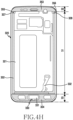
- FIG. 1 is a perspective view illustrating a front side of an electronic device according to various embodiments of the present disclosure.
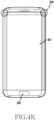
- FIG. 2 is a perspective view illustrating a rear side of the electronic device according to various embodiments of the present disclosure.
- a display 101 may be disposed on the front face of an electronic device 100.
- a receiver 102 may be disposed at one side of the display 101 so as to output the voice of a counterpart.
- a microphone device 103 may be disposed at the other side of the display 101 to transmit the voice of the user to the counterpart.
- components for conducting various functions of the electronic device 100 may be arranged around the receiver 102.
- the components may include one or more sensor modules 104.
- the sensor module 104 may include at least one of, for example, an illuminance sensor (e.g., an optical sensor), a proximity sensor (e.g., an optical sensor), an infrared sensor, and an ultrasonic sensor.
- the components may include a front camera device 105.
- the components may include an indicator 106 (e.g., a light emitting diode (LED) device) configured to allow a user to recognize status information of the electronic device.
- LED light emitting diode
- a speaker 108 may be disposed at one side of the microphone device 103.
- an interface connector port 107 may be disposed in order to perform a transmission/reception function of an external device as well as to charge the electronic device 100 by receive external power.
- an ear jack hole 109 may be disposed at one side of the interface connector port 107.
- the electronic device 100 may include a metallic member 110 as a housing.
- the metallic member 110 may be arranged along the rim of the electronic device 100, and may be disposed to expand to at least a partial region of the rear face of the electronic device 100 that extends from the rim.
- the metallic member 110 defines at least a portion of the thickness of the electronic device 100 along the rim of the electronic device 100, and may be formed in a closed loop shape. Without being limited thereto, however, the metallic member 110 may be formed to serve as at least a portion of the thickness of the electronic device 100.
- the metallic member 110 may be at least partially embedded in the inside of the electronic device 100.
- a rear window 111 may be disposed on the rear face of the electronic device 100.
- a rear camera device 112 may be disposed on the rear window 111 of the electronic device 100, and one or more electronic components 113 may be disposed at one side of the rear camera device 112.
- the electronic components 113 may include at least one of, for example, an illuminance sensor (e.g., an optical sensor), a proximity sensor (e.g., an optical sensor), an infrared sensor, an ultrasonic sensor, a heart rate sensor, and a flash device.
- the display 101 may include a window 1012 disposed to be exposed to the front face of the electronic device 100 and a display module (not illustrated) disposed inside the electronic device and behind the window 1012.
- a display module (not illustrated) disposed inside the electronic device and behind the window 1012.
- an image displayed on the display module may be provided to the user through the window 1012 that is made of a transparent material.
- the window 1012 may be made using various materials, such as transparent glass and acryl.
- the electronic device 100 may include a waterproof structure.
- the electronic device 100 may include at least one seal member (not illustrated) disposed therein for waterproofing.
- at least one seal member may be disposed between the display module and the housing in at least the display region of the display 101.
- a black mask (BM) region may be reduced in, or excluded from, the display region in the electronic device.
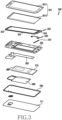
- FIG. 3 is an exploded perspective view illustrating an electronic device according to various embodiments of the present disclosure.
- the electronic device 300 of FIG. 3 may be an embodiment of an electronic device that is similar to, or different from, the electronic device 100 of FIGS. 1 and 2 .
- the electronic device 300 may include a key input device 330, at least one seal member 350, and a display 301 including a display module 301 and a window 3011, in which the key input device 330, the seal member 350, and the display 301 are arranged in this order at the upper side with reference to the housing 320.
- the electronic device 300 may include a printed circuit board (PCB) 360 (e.g., a PCB or aflexible PCB (FPCB)), a battery pack 370, a wireless power transmission/reception member 380, a rear seal member 390, and a rear window 311, which are disposed in this order at the lower side with reference to the housing 320.
- PCB printed circuit board
- FPCB flexible PCB
- the battery pack 370 may be accommodated in an accommodation space formed in the housing 320 for the battery pack 370, avoiding the printed circuit board 360.
- the battery pack 370 and the printed circuit board 360 may be disposed in parallel to each other without overlapping with each other.
- the housing is used alone in an embodiment of the present disclosure, at least one middle plate, which is coupled to the housing, may be used together with the housing.
- the display 301 may be applied to the housing 320 after the display module 3012 is attached to the rear face of the window 3011.
- the display module 3012 may include a touch sensor.
- the display module may include a touch sensor and/or a pressure sensor.
- the seal member 350 may be disposed between the housing 320 and the display 401.
- the seal member 350 may include a plurality of seal members 351, 352, 353, and 354, and the plurality of seal members 351, 352, 353, and 354 may be formed in a shape that corresponds to the rims of the window 3011 and the housing 320. Accordingly, when the housing 320 and the display 301 are coupled to each other via the seal member 350, water infiltration into the inside of the electronic device may be prevented by the seal member 350.
- the seal member 350 in a display module arrangement position of the electronic device 300, is attached between the rear face of the display module 3012 and the housing 320, and in the other regions, the seal member may be attached between the rear face of the window 3011 and the housing 320. According to an embodiment, because at least a portion of the seal member 350 is arranged on the rear face of the display module 3012, the BM region may be reduced in, or excluded from, the display arrangement region in the electronic device 300 by the arrangement of the seal member 350.
- a rear seal member 390 may be arranged along the rims of the housing 320 and the rear window 311.
- a single seal member having a closed loop shape may be used as the rear seal member 390.
- at least two seal members may be arranged in a manner of being connected to each other. Accordingly, when the housing 320 and the display 311 are coupled to each other via the rear seal member 390, water infiltration into the inside of the electronic device may be prevented by the rear seal member 390.
- the rear window 311 may be formed of at least one of glass, plastic, composite resin, and metal.
- the seal member 350 and the rear seal member 390 may include at least one of tape, adhesive, waterproof dispensing, silicone, waterproof rubber, and urethane.
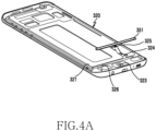
- FIGS. 4A , 4B , 4C , 4D , 4E , 4F , 4G , 4H , 4I , 4J , 4K , 4L ,and 4M are views sequentially illustrating a process of arranging the seal member 350 that is arranged in the electronic device 300 of FIG. 3 according to various embodiments of the present disclosure.
- FIGS. 4A and 4B are views illustrating a state in which a first seal member 351 is arranged in the housing 320 of an electronic device according to various embodiments of the present disclosure.
- the housing 320 may include a first seal member receiving portion 326 formed on the front face 321 thereof.
- the first seal member receiving portion 326 may be formed in a widthwise direction along the lower rim of the display module arrangement region of the housing320 (the region S1 in FIG. 4B ).
- the housing 320 may include a key input device mounting portion 323 that is provided in a region S3 (see FIG. 4B ) other than the display module arrangement region of the housing 320 so as to arrange a key input device 330 (see FIG. 4C ) (e.g., a home button) therein.
- the front face 321 of the housing 320 may include a printed circuit receiving portion 324 formed to guide a printed circuit (e.g., an FPCB) that is drawn out from the key input device.
- the printed circuit receiving portion 324 may include a through-hole 325 through which the printed circuit of the key input device is penetrated to be electrically connected to a print circuit board that is arranged to face the rear face of the housing 320.
- the printed circuit receiving portion 324 may be arranged across the first seal member receiving portion 326. This is due to fact that the first seal member 351 is arranged in the display module arrangement region S1, and the key input device is arranged in the other region (the region S3). Accordingly, a waterproof structure may be required by the printed circuit of the key input device. According to an embodiment, the key input device may be arranged in the region S2 other than the display module arrangement region S1 of the housing.
- the first seal member 351 may be fixed to the housing 320 in the manner of being received in the first seal member receiving portion 326 before the key input device is arranged.
- the first seal member 351 may include at least one of tape, adhesive, waterproof dispensing, silicone, waterproof rubber, and urethane.
- FIG. 4C is a view illustrating a state in which the key input device 330 is arranged in the housing 320 of an electronic device according to various embodiments of the present disclosure.
- the key input device 330 may be arranged on the front face 321 of the housing 320 such that, in a state where the first seal member 351 is fixed in the first seal member receiving portion 326, at least a portion of the printed circuit 332 overlaps with the first seal member 351 in a manner of crossing with the upper side of the first seal member 351.
- the key button 331 of the key input device 330 is fixed in a manner of being received in the key input device receiving portion 323, and the printed circuit 332 drawn out from the key button 331 may be arranged in a manner of being guided by the printed circuit receiving portion 324 of the housing 320 and being penetrated into the inside housing through the through-hole 325.
- an end of the printed circuit 332 may include a connector 333 that is penetrated through the through-hole 325 and is then electrically connected to a print circuit board that is arranged on the rear face of the housing 320.
- FIGS. 4D , 4E ,and 4F are views illustrating a state in which a second seal member 352 is arranged in the housing 320 of an electronic device according to various embodiments of the present disclosure.
- a second seal member 352 may be arranged in a state where the first seal member 351 and the key input device 330 are arranged in the housing 320.
- the second seal member receiving portion 352 may be formed along the rim of the display module arrangement region (the region S1 in FIG. 4E ).
- the second seal member 352 includes a left rim region extending in the left rim region of the display module arrangement region, a lower rim region extending in the lower rim region of the display module arrangement region, and a right rim region extending in the right rim region of the display module arrangement region.
- the printed circuit 332 of the key input device 330 may be arranged to be interposed between the first seal member 351 and the second seal member 352, and the portion of the printed circuit 332, which crosses the upper side of the first seal member 351 may be sealed by the first and second seal members 351 and 352, which have elasticity.
- the second seal member 352 may include at least one of tape, adhesive, waterproof dispensing, silicone, waterproof rubber, and urethane.
- an additional filling member introduction hole may be further arranged in the corresponding region.
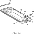
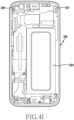
- FIGS. 4G and 4H are views illustrating a state in which a third seal member 353 and a fourth seal member 354 are arranged in the housing 320 of an electronic device according to various embodiments of the present disclosure.
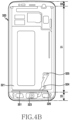
- FIG. 4I is a view illustrating the housing 320 of an electronic device that is provided with third and fourth filling member introduction holes 327 and 328 for introducing a waterproofing filling member according to various embodiments of the present disclosure.
- the third seal member 353 and the fourth seal member 354 may be arranged in a state where the first seal member 351, the key input device 330, and the second seal member 352 are arranged.
- the third seal member 353 is arranged in the upper region (the region S2 shown in FIG. 4H ) of the display module arrangement region (the region S1) of the housing 320.
- the fourth seal member 354 may be arranged in the lower region (the region S3 shown in FIG. 4H ) of the display module arrangement region (the region S1) of the housing 320.
- gaps 355 and 356 may be generated by stepped portions between the display module arrangement region (the region S1) and the region (the region S2) above the display module arrangement region, and the gaps 355 and 356 may be sealed by adding a waterproofing filling member to be described later.
- filling member introduction holes 327 and 328 are formed at the regions corresponding to the gaps 355 and 356, respectively, to introduce a waterproofing filling member through the rear face 329 of the housing 320.
- the filling member introduction holes 327 and 328 are formed in order to seal the gaps 355 and 356 generated in the boundary portion between the second seal member 352 and the third seal member 353.
- an additional filling member introduction hole may be further arranged in the corresponding region in order to seal a gap generated in a boundary region between the second seal member 352 and the fourth seal member 354.
- an additional filling member introduction hole may be further arranged in order to seal a gap between constituent products, such as a fixing member and an FPCB that are related to the key input device 330, and the second seal member 352 or the fourth seal member 354.
- the third seal member 353 and the fourth seal member 354 may include at least one of tape, adhesive, waterproof dispensing, silicone, waterproof rubber, and urethane.
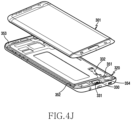
- FIGS. 4J to 4K are views illustrating a state in which a display 301 is disposed in the housing 320 in which the first to fourth seal members 351 to 354 are arranged according to various embodiments of the present disclosure.
- the display 301 may be arranged thereabove.
- the display module 3012 of the display 301 may be sealed in such a manner in which the rear face of the display module 3012 is in contact with the second seal member 352, an upper region other than the display module arrangement region may be sealed in such a manner in which the rear face of the window is in contact with the third seal member 353, and a lower region other than the display module arrangement region may be sealed in such a manner in which the rear face of the window is in contact with the fourth seal member 354.
- the region indicated by a dotted line in FIG. 4K is a boundary portion between the second seal member 352 and the third seal member 353 where a gap is generated and may be sealed by an additional waterproofing filling member.
- the gap generated in a boundary portion between the second seal member 352 and the fourth seal member 354 may also be sealed by an additional waterproofing filling member.
- FIGS. 4L and 4M are views illustrating a state in which a waterproofing filling member is applied to a filling member introduction hole according to various embodiments of the present disclosure.
- the display 301 coupled to the housing 320 may include a window 3011 and a display module 3012 attached to the rear face of the window 3011 and having a predetermined thickness. Accordingly, due to different heights, gaps 355 and 356 (e.g., stepped portions) may be formed between the regions (the regions S2 and S3) (e.g., the BM region) with which the window 3011 of the housing 320 is in contact and the display module arrangement region (the region S1) in which the display module 3012 of the housing 320 is arranged.
- the BM regions (the regions S2 and S3) may be formed to be higher than the display module arrangement region (the region S1).
- the second seal member 352 and the third seal member 353 are arranged to be spaced apart from each other in the gap 355 and 356 regions where the second seal member 352 and the third seal member 353 meet, and thus it is necessary to seal the second seal member 352 and the third seal member 353.
- a waterproofing filling member 340 is introduced through the filling member introduction holes 327 and 328 of the rear face 329 of the housing.
- the filling member introduction holes 327 and 328 may be subjected to a finishing processing by a separate cover or the like.
- the waterproofing filling member 340 may include a semisolid material or a liquid material, and may be solidified by a natural or external condition (e.g., heat, ultraviolet ray, or pressure). Accordingly, in the electronic device, it is possible to provide a space sealed by a closed curve loop having no discontinuous section in order to implement a complete waterproof function by applying a plurality of seal members 351, 352, 353, and 354 and the waterproofing filling member 340 between the display 301 and the housing 320.
- a natural or external condition e.g., heat, ultraviolet ray, or pressure
- FIG. 4N is a view illustrating a state in which a waterproofing filling member is applied to a housing before a display is applied according to various embodiments of the present disclosure.
- the display 301 may be attached to the housing 320 via the plurality of seal members 351, 352, 353, and 354 after the waterproofing filling member 341 is applied to the regions 341 and 342 corresponding to the gaps 355 and 356 of the housing 320 before the display 301 is applied to the housing 320.
- FIG. 5A is a view illustrating a state in which a seal member is disposed in a housing according to various embodiments of the present disclosure.
- a housing 500 shown in FIG. 5A may be an embodiment of a housing that is similar to, or different from, the housing 320 of FIG. 4C or a combination in which the housing 320 of FIG. 4C and a middle plate are combined with each other.
- the housing 500 may include a display module arrangement region (region A1) and BM regions (regions A2 and A3) formed in the upper and lower ends of the display module arrangement region.
- a seal member 510 may be disposed along the rim of the housing 500.
- the seal member 510 may be formed in a single body to have a closed loop shape.
- the seal member 510 may include at least one of tape, adhesive, waterproof dispensing, silicone, waterproof rubber, and urethane.
- the seal member 510 may form a sealing space for waterproof because it comes in close contact with the rim of a display that includes a window.
- the seal member 510 may include a first seal member 511 arranged on the left rim of the housing 500 and a second seal member 512 arranged on the right rim of the housing 500.
- the first and second seal members 511 and 512 may contribute to sealing the display arrangement region (the region A1) of the housing 500.
- the seal member 510 may include a third seal member 513 arranged on the upper rim of the housing 500 and a fourth seal member 514 arranged on the lower rim of the housing 500.
- the third and fourth seal members 513 and 514 may contribute to sealing the BM regions A2 and A3 of the housing 500.
- the first to fourth seal members 511, 512, 513, and 514 may be formed in a single body.
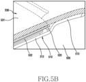
- the display 530 coupled to the housing 500 may include a window 531 (see FIG. 5B ) and a display module 532 (see FIG. 5B ) attached to the rear face of the window 3011 and having a predetermined thickness. Accordingly, due to different heights, a stepped portion 520 may be formed between the BM regions (the regions A2 and A3) with which the window 531 of the housing 500 is in contact and the display module arrangement region (the region A1) in which the display module 532 of the housing 500 is arranged. For example, the BM regions (the regions A2 and A3) may be formed to be higher than the display module arrangement region (the region A1).
- the seal member 510 may come in close contact with, and may be closely attached to, a face of the housing 500 to correspond to the stepped portion 520.
- the stepped portion 520 may be formed in the boundary region between the first to fourth seal members 511, 512, 513, and 514 of the illustrated housing 500 (the portions indicated by dotted lines at four corners of the illustrated housing).
- FIG. 5B is a view illustrating a state in which a display is arranged on an upper portion of a housing in which a seal member is arranged according to various embodiments of the present disclosure.
- FIG. 5C is a view illustrating a state in which a waterproofing filling member is applied between a seal member and a display according to various embodiments of the present disclosure.
- the display 530 may be stacked on the housing 500 where the seal member 510 is attached.
- the display 530 may include a window 531 made of a transparent material and a display module 532 arranged on the rear face of the window 531.
- the display module 532 of the display 530 in the case where the display 530 is arranged on the top face of the housing 500, the display module 532 of the display 530 may be positioned in the display module arrangement region (the region A1 in FIG. 5A ) of the housing 500, and the window 531 may be arranged in the BM regions (the regions A2 and A3 in FIG. 5A ) of the housing 500.
- the display arrangement region the region A1 in FIG.
- the display 530 may be fixed in a manner in which the rear face of the display module 532 is attached to a seal member 510 (e.g., the first and second seal members 511 and 512 in FIG. 5A ), and in the BM regions (the regions A2 and A3 in FIG. 5A ), the display may be fixed in a manner in which the corresponding rear face of the window 531 is attached to a seal member 510 (e.g., the third and fourth seal members 513 and 514 in FIG. 5A ).
- a seal member 510 e.g., the first and second seal members 511 and 512 in FIG. 5A
- the display may be fixed in a manner in which the corresponding rear face of the window 531 is attached to a seal member 510 (e.g., the third and fourth seal members 513 and 514 in FIG. 5A ).
- a stepped portion 520 may generate a gap by the thickness of the display module 532, and water may flow into the stepped portion, which may consequently cause water infiltration into the electronic device.
- a separate waterproofing filling member 540 may be applied to such a stepped portion 520.
- the waterproofing filling member 540 may include a semisolid material or a liquid material, and may be solidified by a natural or external condition (e.g., heat, ultraviolet ray, or pressure). Accordingly, in the electronic device, it is possible to provide a space sealed by a closed curve loop having no discontinuous section in order to implement a complete waterproof function by applying the seal member 510 and the waterproofing filling member 540 between the display 630 and the housing 500.
- FIG. 6A is a view illustrating a state in which a seal member is arranged in a housing according to various embodiments of the present disclosure.
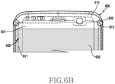
- FIGS. 6B and 6C are views illustrating a state in which a display is arranged on an upper portion of a housing in which a seal member is arranged according to various embodiments of the present disclosure.
- a housing 600 shown in FIG. 6A may be similar to the housing 320 or FIG. 4C or an assembly in which the housing 320 shown FIG. 4C and a middle plate are assembled, or an embodiment of a housing similar to, or different from, the housing 500 shown FIG. 5A .
- the housing 600 may include a display module arrangement region (region B1) and BM regions (regions B2 and B3) formed in the upper and lower ends of the display module arrangement region.
- a seal member 610 may be arranged along the rim of the housing 600.
- the seal member 610 may be arranged along the rim of the housing 600 to have a loop shape.
- the seal member 610 may include at least one of tape, adhesive, waterproof dispensing, silicone, waterproof rubber, and urethane.
- the seal member 610 may form a sealing space for waterproof because it comes in close contact with the rim of a display that includes a window.
- the seal member 610 may include a first seal member 611 arranged on the left rim of the housing 600 and a second seal member 612 arranged on the right rim of the housing 600.
- the first and second seal members 611 and 612 may contribute to sealing the display arrangement region (the region B1) of the housing 500.
- the seal member 610 may include a third seal member 613 arranged on the upper rim of the housing 600 and a fourth seal member 614 arranged on the lower rim of the housing 600.
- the third and fourth seal members 613 and 614 may contribute to sealing the BM regions B2 and B3 of the housing 600.
- the first to fourth seal members 611, 612, 613, and 614 may be individually formed.
- the display 630 coupled to the housing 600 may include a window 631 and a display module 632 attached to the rear face of the window 631 and having a predetermined thickness. Accordingly, due to different heights, a stepped portion 620 may be formed between the BM regions (the regions B2 and B3) with which the window 631 of the housing 600 is in contact and the display module arrangement region (the region B1) in which the display module 632 of the housing 600 is arranged.
- the BM regions (the regions B2 and B3) may be formed to be higher than the display module arrangement region (the region B1).
- the stepped portion 620 may be formed in the boundary region between the first to fourth seal members 611, 612, 613, and 614 of the illustrated housing 600 (the portions indicated by dotted lines at four corners of the illustrated housing).
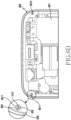
- FIG. 6D is a view illustrating a portion of a housing having a filling member introduction hole for introducing a waterproofing filling member according to various embodiments of the present disclosure.
- filling member introduction holes 6011 and 6012 may be formed from the rear face 601 of the housing 600 to the front face of the housing 600 in order to apply a waterproofing filling member 640.
- the filling member introduction holes 6011 and 6012 may be formed in a region corresponding to the above-mentioned stepped portion 620.
- the waterproofing filling member 640 may be introduced into the stepped portion 620 formed on the front face of the housing 600 through the filling member introduction holes 6011 and 6012 by using a separate tool.
- the housing 600 and the display 630 may be in the state of being coupled to each other by the seal member 610, and in the coupled state, the waterproofing filling member 640 may be coated through the filling member introduction holes 6011 and 6012.
- the filling member introduction hole 6012 may be subjected to a finishing processing by a separate cover or the like.
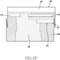
- FIGS. 6E and 6F are views illustrating a state in which a waterproofing filling member is applied between a housing and a display according to various embodiments of the present disclosure.
- the display 630 may be stacked on the housing 600 where the seal member 610 is attached.
- the display 630 may include a window 631 made of a transparent material and a display module 632 on the rear face of the window 631.
- the display module 632 of the display 630 in the case where the display 630 is arranged on the top face of the housing 600, the display module 632 of the display 630 may be positioned in the display module arrangement region (the region B1 in FIG. 6A ) of the housing 600, and the window 631 may be arranged in the BM regions (the regions B2 and B3 in FIG. 6A ) of the housing 600.
- the display arrangement region the region B1 in FIG.
- the display 630 may be fixed in a manner in which the rear face of the display module 632 is attached to a seal member 610 (e.g., the first and second seal members 611 and 612 in FIG. 6A ), and in the BM regions (the regions B2 and B3 in FIG. 6A ), the display may be fixed in a manner in which the corresponding rear face of the window 631 is attached to a seal member 610 (e.g., the third and fourth seal members 613 and 614 in FIG. 6A ).
- a seal member 610 e.g., the first and second seal members 611 and 612 in FIG. 6A
- the display may be fixed in a manner in which the corresponding rear face of the window 631 is attached to a seal member 610 (e.g., the third and fourth seal members 613 and 614 in FIG. 6A ).
- a separate waterproofing filling member 640 may be applied to such a stepped portion 620.
- the waterproofing filling member 640 may be introduced into the filling member introduction holes 6011 and 6012 through the rear face 601 of the housing 600 in the state where the display 630 and the housing 600 are coupled to each other.
- the waterproofing filling member 640 may include a semisolid material or a liquid material, and may be solidified by a natural or external condition (e.g., heat, ultraviolet ray, or pressure). Accordingly, in the electronic device, it is possible to provide a space sealed by a closed curve loop having no discontinuous section in order to implement a complete waterproof function by applying the seal member 610 and the waterproofing filling member 640 between the display 630 and the housing 600.
- a natural or external condition e.g., heat, ultraviolet ray, or pressure
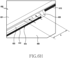
- FIGS. 6G and 6H are views illustrating a configuration of a display to which a waterproofing filling member is applied according to various embodiments of the present disclosure.
- the housing 600 may include a display 630 fixed by the first seal member 611, the second seal member 612, and the third seal member 613.
- the display 630 may include a window 631 and a display module 633 arranged on the rear face of the window 631.
- the display module 633 may be fixed in a manner in which the rear face of the display module 633 is attached to the top face of the housing 600 by the first seal member 611 and the second seal member 612.
- the upper region of the window 631 other than the display module 633 may be fixed in a manner in which the rear face of the window 631 is attached to the top surface of the housing 600 by the third seal member 613.
- the lower region of the window 631 may also be attached to the housing 600 in the same manner as the upper region.
- the seal members 611, 612, and 613 may include at least one of tape, adhesive, waterproof dispensing, silicone, waterproof rubber, and urethane.
- the seal members 611, 612, and 613 may form a sealing space for waterproof because they come in close contact with the rim of a display that includes a window.
- the display 630 coupled to the housing 600 may include a window 631 and a display module 633 attached to the rear face of the window 631. Accordingly, due to different heights, a stepped portion 620 (e.g., a gap region) may be formed between the black mask (BM) regions (the regions A2 and A3), other than the display module 633 arrangement region with which the window 631 of the housing 600 is in contact, and the display module arrangement region in which the display module 633 of the housing 600 is arranged. According to an embodiment, the stepped portion 620 may be sealed from the outside of the electronic device by introducing a waterproofing filling member into the stepped portion 620 through the filling member introduction holes 6013 and 6014 (see FIG. 6I ) formed in the housing 600, as described above.
- BM black mask
- the stepped portion 620 may be sealed from the outside of the electronic device by introducing a waterproofing filling member into the stepped portion 620 through the filling member introduction holes 6013 and 6014 (see FIG. 6I )
- the display module 633 of the display 630 may be attached to the housing 600 via the seal members 611, 612, and 613 to implement a waterproof space in the inside of the electronic device.
- a reversely stepped section h (see FIG. 6H ) is generated in at least a portion in a lateral space formed by the window 631, the housing 600, and the display module 633 depending on the type of the applied display module (e.g., an OCTA display module or a Super AMOLED display module).
- the waterproofing filling member is not completely filled to the reversely stepped portion that is generated due to a length difference between the constituent elements of the display module (e.g., a polarizing panel, an encap layer, and alow temperature polysilicone (LTPS)), and water may flow into such a space.
- the constituent elements of the display module e.g., a polarizing panel, an encap layer, and alow temperature polysilicone (LTPS)
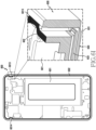
- FIG. 6I is a view illustrating a configuration of a housing to which a waterproofing filling member is applied according to various embodiments of the present disclosure.
- FIG. 6J is a view illustrating a state in which a waterproofing filling member is applied according to various embodiments of the present disclosure.
- the housing 600 may be configured such that a reversely stepped portion of the display may be included in a sealing region. According to an embodiment, the housing 600 may be configured such that a reversely stepped portion of the display and a sealing line partially intersect with each other and the reversely stepped portion does not extend out of the sealing region. According to an embodiment, the housing 600 may include a seal member attachment portion 602 to allow the rear housing to be attached along the rear face 601. According to an embodiment, the filling member introduction holes 6013 and 6014 may be formed in the seal member attachment portion 602 of the housing 600.
- the filling member introduction holes 6013 may be used as an introduction hole, through which a waterproofing filling member may be introduced so as to seal a stepped portion 620 between the display 630 attached to the front face of the housing 600 via the seal members 611, 612, and 613 and the housing 600.
- the filling member introduction holes 6013 and 6014 may be, but not exclusively, formed in the seal member attachment portion 602.
- the filling member introduction holes 6013 and 6014 may be arranged inside or outside, avoiding the seal member attachment portion 602.
- the filling member introduction holes 6013 and 6014 may be located at a position to be capable of entirely sealing the reversely stepped section h (see FIG. 6H ) of the display module 633 (e.g., a position that overlaps with the side portion of the display module in which the reversely stepped section is included).
- the filling member introduction holes 6013 and 6014 may be formed to have a size that includes both of at least a partial region of a seal member arranged on a side face of the housing 600 (e.g., the first seal member and the second seal member) and at least a partial region of a seal member arranged on the top surface of the housing 600 (e.g., the third seal member).
- the filling member introduction holes 6013 and 6014 may be formed to have a space and/or a size such that the waterproofing filling member 640 introduced through the filling member introduction holes 6013 and 6014 may be coated on all of the reversely stepped section h (see FIG. 6H ) of the display module 633, at least a partial region of a seal member arranged on a side face of the housing 600 (e.g., the first seal member and the second seal member), and at least a partial region of a seal member arranged on the top surface of the housing 600 (e.g., the third seal member).
- a rear housing fixing seal member may be attached onto the waterproofing filling member 640.
- the waterproofing filling member 640 may include a semisolid material or a liquid material, and may be solidified by a natural or external condition (e.g., heat, ultraviolet ray, or pressure).
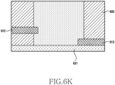
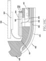
- FIG. 6K is a sectional view taken along line J1-J1' of FIG. 6J .
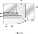
- FIG. 6L is a sectional view taken along line J2-J2' of FIG. 6J .
- the waterproofing filling member 640 may be coated in a manner in which the second seal member 612 and the third seal member 613 are sealed without being discontinued. At the same time, the coated waterproofing filling member 640 is pushed to the boundary region between the window 631 of the display module 633 and the housing 600 while also entirely sealing the reversely stepped section of the display module 633 such that the waterproofing filling member 640 may also naturally perform the sealing function between the window 631 and the housing 600. By such an additional sealing effect, an additional seal member (e.g., a waterproof film) to be described later may be excluded.
- an additional seal member e.g., a waterproof film
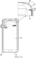
- FIG. 7A is a view illustrating the rear side of a display to which a waterproofing filling member is applied according to various embodiments of the present disclosure.
- the display 730 may include a window 731 and a display module 732 arranged on the rear face of the window 731.
- a waterproofing filling member is applied to the stepped portion between the display module arrangement region of the housing and the BM regions of the window after the display is attached to the housing via seal members.
- the present embodiment discloses a method in which, before the display 730 is applied to the housing 700 (see FIG. 7B ), the waterproofing filling member 740 is applied to a display region 721, which corresponds to a stepped portion 720 (see FIG. 7B ) of the housing 700, first, and then the display 730 is attached to the housing 700 via a seal member 710 (see FIG. 7B ).
- the waterproofing filling member 740 may include a semisolid material or a liquid material, and may be solidified by a natural or external condition (e.g., heat, ultraviolet ray, or pressure).
- a region 721 of the display 730 which corresponds to a stepped portion of the housing, may be included in the vicinity of four corners of the display 730 where the display module 732 is terminated and the window 731 is initiated, and a waterproofing filling member 740 may be applied (e.g., by coating) to the corresponding region first.
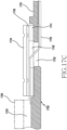
- FIG. 7B is a view illustrating an arrangement of a waterproofing filling member when a display and a housing are coupled to each other according to various embodiments of the present disclosure.
- FIG. 7C is a view illustrating a state in which a waterproofing filling member is applied between a housing and a display according to various embodiments of the present disclosure.
- a seal member 710 may be arranged on a face of the housing 700, to which the display 730 is applied, along a rim thereof.
- the seal member 710 may include at least one of tape, adhesive, waterproof dispensing, silicone, waterproof rubber, and urethane.
- the seal member 710 may include a first seal member 712 arranged on a rim region of the housing 740 in which the display module 732 of the display 730 is disposed, and a second seal member 713 arranged on a BM region of the housing 700, to which, rather than the display module, the rear face of the window 731 is directly applied.
- a stepped portion 720 may be formed in the boundary region between the display module arrangement region and the BM region of the housing 700.
- the stepped portion 720 may include a space in which a first seal member 712 and a second seal member 713 are spaced from each other without extending.
- the first seal member 712 and the second seal member 713 may be integrally arranged without being discontinued in such a manner of being in close contact with the top face of the stepped portion 720.
- the display 730 may be applied in a manner of being stacked thereon.
- the rear face of the display module 732 of the display 730 may be attached to the first seal member 712.
- the window 731 of the display 730 may be attached to the second seal member 713.
- the waterproofing filling member 740 coated on the boundary portion 721 between the display module 732 and the window 731 of the display 730 may seal a gap generated between the housing 700 and the display 730 by the stepped portion 720 at a position corresponding to the stepped portion 720 of the housing 700.
- the waterproofing filling member 740 may be applied to a face of the display and/or the window in the vicinity of the boundary portion 721 between the display module 732 and the window 731. Accordingly, in the electronic device, it is possible to provide a space sealed by a closed curve loop having no discontinuous section in order to implement a complete waterproof function by applying the seal member 710 and the waterproofing filling member 740 between the display 730 and the housing 700.
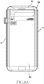
- FIGS. 8A to 8C are views illustrating a state in which a waterproofing filling member is applied to both side faces of a display coupled to a housing according to various embodiments of the present disclosure.
- the display 830 may include a window 831 and a display module 832 at least partially arranged on the rear face of the window 831.
- a display module 832 of the display 830 in a case where the display module 832 of the display 830 is attached to the outer face of the housing by a seal member, side face regions (e.g., regions C1 and C2 in FIG. 8A ) of the display 830 arranged outside the seal member may also be exposed to the outside.
- a sealed space for waterproof may be formed inside the electronic device, but the side face regions (regions C1 and C2 in FIG.
- a separate side face seal member e.g., a waterproof film
- a separate side face seal member e.g., a waterproof film
- FIG. 8B is a sectional view of a housing 800, to which a flexible display module 832 is applied, in which a display 830 may be attached to the housing 800.
- the display module 832 of the display 830 may be attached to the housing 800 via a seal member to implement a waterproof space inside the electronic device.
- a side space 822 formed by the window 831, the housing 800, and the display module 832 may be exposed to the outside, and foreign matter or water may be infiltrated into such a space, which may cause the display module 832 to be damaged.
- a side face seal member 840 e.g., a waterproof film or a water-repellent film
- a side face seal member 840 may be applied to such a space 822.
- the side face seal member 840 may include at least one of a water-repellent coating material containing fluorine, a liquid acryl-based adhesive, an adhesive having elasticity and recovering force, a waterproof dispensing, silicone, and waterproof rubber.
- FIG. 8C is a sectional view of a housing 850, to which an OCTA display module 882 is applied, in which a display 880 may be attached to the housing 850.
- the display module 882 of the display 880 may be attached to the housing 850 via a seal member to implement a waterproof space inside the electronic device.
- a side space 860 formed by the window 881, the housing 850, and the display module 882 may be exposed to the outside, and foreign matter or water may be infiltrated into such a space 860, which may cause the display module 882 to be damaged.
- a side face seal member 870 (e.g., a waterproof film or a water-repellent film) may be applied to such a space 860.
- the side face seal member 870 may include at least one of a water-repellent coating material containing fluorine, a liquid acryl-based adhesive, an adhesive having elasticity and recovering force, a waterproof dispensing, silicone, and waterproof rubber.
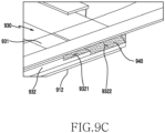
- FIGS. 9A to 9C are views illustrating a state in which a waterproofing filling member is applied to a space generated by a structure of a display module according to various embodiments of the present disclosure.
- FIGS. 9B and 9C are perspective views illustrating a main part when viewed in a direction indicated by line D-D' in FIG. 9A .
- the display 930 may include a window 931 and a display module 932 at least partially arranged on the rear face of the window 931.
- a side face region of the display 930 arranged outside the seal member 912 may also be exposed to the outside.
- a sealed space for waterproof may be formed inside the electronic device, but the side face region of the display 930, which is positioned outside the seal member 912, may be exposed to the outside.
- respective constituent elements of the display module 932 which are exposed to a side face of the display 930, may be arranged to form a stepped portion in a vertical direction (in the z-axis direction).
- a stepped structure a plurality of water infiltration spaces 9321 and 9322 may be generated on the side faces of the display 930.
- a side face seal member 940 e.g., a waterproof film or a water-repellent film
- the side face seal member 940 may include at least one of a water-repellent coating material containing fluorine, a liquid acryl-based adhesive, an adhesive having elasticity and recovering force, a waterproof dispensing, silicone, and waterproof rubber.
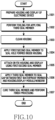
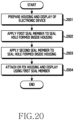
- FIG. 10 is a flowchart illustrating a process in which at least one seal member is disposed in an electronic device according to various embodiments of the present disclosure.
- a housing of an electronic device and a display applied to the housing may be prepared.
- the housing may, but not exclusively, form a single component.
- the housing may be defined as a combination in which an external housing and at least one middle plate (e.g., a bracket) are combined with each other.
- a combination in which a synthetic resin material, a metallic material, and/or a hetero-material are combined with each other may be applied to the housing.
- the display may include a window made of a transparent material and a display module arranged on the rear face of the window.
- the display module may include a touch sensor, and, in such a case, the display may be used as a touch screen.
- a tooling operation may be performed so as to apply the third seal member.
- the third seal member may be applied to a gap formed by a stepped portion formed in a boundary of the housing in which the first seal member and the second seal member are arranged.
- an introduction hole may be formed at the corresponding position of the housing.
- an operation of cleaning the housing, for which the tooling operation has been finished may be performed.
- a cleaning operation may be performed in order to remove the machining particles.
- the first and second seal members may be applied in order to seal holes formed inside the cleaned housing.
- the first seal member may be attached to a region of the housing in which the display module is arranged.
- the second seal member may be attached to a region of the housing other than the region in which the display module is arranged.
- the first seal member and the second seal member may be formed as a single body.
- first seal member and the second seal member may be individually formed to be arranged on corresponding regions, respectively.
- first seal member and the second seal member may include at least one of tape, adhesive, waterproof dispensing, silicone, waterproof rubber, and urethane.
- the housing and the display may be attached to each other by using the first seal member and the second seal member.
- the first seal member may attach the display module of the display to the housing.
- the first seal member may attach the rear face of the display module of the display and a face of the housing to each other.
- the second seal member may attach the window and the housing to each other.
- the second seal member may attach the rear face of the window, which corresponds to a BM region of the display, and a face of the housing to each other.
- the third seal member may be applied in order to seal a gap between the first waterproof member and the housing, the housing, and the display.
- the third seal member may be introduced through an introduction hole in the rear face of the housing.
- the third seal member may be introduced into a gap formed in the boundary portion between the first seal member and the second seal member.
- the third seal member is a waterproofing filling member, which may include a semisolid material or a liquid material, and may be solidified by a natural or external condition (e.g., heat, ultraviolet ray, or pressure).
- the third seal member may include a waterproof film applied to a side face of the display module and the housing, which are attached to each other by the first seal member.
- an operation of curing and finishing the third seal member may be performed.
- a complete waterproof function may be implemented in the electronic device by providing a sealed space by a closed curve loop that does not have a discontinuous section by the first, second, and third seal members.
- an electronic device formed as illustrated in FIGS. 5A , 5B , 5C , 6A , 6B , 6C , 6D , 6E ,and 6F described above may be manufactured by using the manufacturing method of FIG. 10 .
- FIG. 11 is a flowchart illustrating a process in which at least one seal member is disposed in an electronic device according to various embodiments of the present disclosure.
- a housing of an electronic device and a display applied to the housing may be prepared.
- the housing may, but not exclusively, form a single component.
- the housing may be defined as a combination in which an external housing and at least one middle plate (e.g., a bracket) are combined with each other.
- a combination in which a synthetic resin material, a metallic material, and/or a hetero-material are combined with each other may be applied to the housing.
- the display may include a window made of a transparent material and a display module arranged on the rear face of the window.
- the display module may include a touch sensor, and, in such a case, the display may be used as a touch screen.
- the first and second seal members may be applied in order to seal holes formed inside the housing.
- the first seal member may be attached to a region of the housing in which the display module is arranged.
- the second seal member may be attached to a region of the housing other than the region in which the display module is arranged.
- the first seal member and the second seal member may be formed as a single body. Without being limited thereto, however, the first seal member and the second seal member may be individually formed to be arranged on corresponding regions, respectively.
- the first seal member and the second seal member may include at least one of tape, adhesive, waterproof dispensing, silicone, waterproof rubber, and urethane.
- the third seal member may be applied in order to seal a gap between the first waterproof member and the housing, the housing, and the display.
- the third seal member may be applied to the boundary portion between the first seal member and the second seal member.
- the third seal member is a waterproofing filling member, which may include a semisolid material or a liquid material, and may be solidified by a natural or external condition (e.g., heat, ultraviolet ray, or pressure).
- the housing and the display may be attached to each other by using the first seal member and the second seal member.
- the first seal member may attach the display module of the display to the housing.
- the first seal member may attach the rear face of the display module of the display and a face of the housing to each other.
- the second seal member may attach the window and the housing to each other.
- the second seal member may attach the rear face of the window, which corresponds to a BM region of the display, and a face of the housing to each other.
- the third seal member may be applied to a gap formed by a stepped portion formed in a boundary of the housing in which the first seal member and the second seal member are arranged, thereby performing a function to seal the gap.
- an operation of curing and finishing the third seal member may be performed.
- a complete waterproof function may be implemented in the electronic device by providing a sealed space by a closed curve loop that does not have a discontinuous section by the first, second, and third seal members.
- an electronic device formed as illustrated in FIGS. 7A , 7B ,and 7C described above may be manufactured by using the manufacturing method of FIG. 10 .
- FIG. 12 is an exploded perspective view illustrating an electronic device that is provided with a seal member according to various embodiments of the present disclosure.
- At least one seal member applied for waterproof may be applied to seal at least one hole formed in the housing that corresponds to the rear face of the display module, rather than a rim of the rear face of the display module.
- the electronic device 1200 of FIG. 12 may be an embodiment of an electronic device that is similar to, or different from, the electronic device 400 illustrated in FIGS. 4A and 4B .
- the electronic device 1200 may include a housing 1210, a display 1220 arranged above the housing 1210, and one or more seal members 1241, 1242, and 1243 interposed between the display 1220 and the housing 1210.
- the display 1220 may include a window 1221 arranged on the front face of the electronic device 1200 and a display module 1222 arranged on the rear face of the window 1221.
- the seal members may include a first seal member 1241 arranged in a region of the housing 1210 which corresponds to the display module 1222, and a second seal member 1242 and a third seal member 1243 which are arranged in a region of the housing 1210 that corresponds to a BM region of the window 1221 and corresponds to a region other than the display module 1222.
- the first, second, and third seal members 1241, 1242, and 1243 may include at least one of tape, adhesive, waterproof dispensing, silicone, waterproof rubber, and urethane.
- the first seal member 1241 may be arranged between the rear face of the display module 1222 and the housing 1210.
- the second seal member 1242 and the third seal member 1243 may be arranged between the rear face of the window 1221 and the housing 1210.
- the electronic device 1200 may secure a BM region that is reduced in, or excluded from, the display region.
- the first seal member 1241 may seal one or more structural holes formed in a region of the housing 1210 which corresponds to the display module 1222, thereby preventing water infiltration into the electronic device.
- the holes may include a through-hole for reducing the protrusion amount of a rear camera or a through-hole for battery swell.
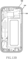
- FIG. 13A is a view illustrating the front side of a housing in which at least one seal member is disposed according to various embodiments of the present disclosure.
- a housing 1310 shown in FIG. 13A may be an embodiment of a housing that is similar to, or different from, the housing 1210 of FIG. 12 .
- a plurality of seal members 1341, 1342, and 1343 of FIG. 13A may be an embodiment of seals that are similar to, or different from, a plurality of seal members 1241, 1242, and 1243 of FIG. 12 .
- the housing 1310 may include a display module arrangement region (region E1) and BM regions (regions E2 and E3) formed in the upper and lower ends of the display module arrangement region.
- the plurality of seal members 1341, 1342, and 1343 may be arranged on the face of the housing 1310 where the display is mounted.
- the seal members 1341, 1342, and 1343 may include at least one of tape, adhesive, waterproof dispensing, silicone, waterproof rubber, and urethane.
- the seal members 1341, 1342, and 1343 may include a first seal member 1341 arranged in a region of the housing 1310 which corresponds to the display module, and a second seal member 1342 and a third seal member 1343 which are arranged in a region of the housing 1310 that corresponds to a BM region of the window and corresponds to a region other than the display module.
- the first seal member 1341 may contribute to sealing at least a portion of the display arrangement region (the region E1) of the housing 1310.
- the second seal member 1342 may be arranged in the upper region (the region E2) of the display module arrangement region of the housing 1310.
- the third seal member 1343 may be arranged in the lower region (the region E3) of the display module arrangement region of the housing 1310.
- the first seal member 1341 may seal one or more structural holes formed in a region (region E1) of the housing 1310 which corresponds to the display module, thereby preventing water infiltration into the electronic device.
- the holes may include a through-hole for reducing the protrusion amount of a rear camera or a through-hole for battery swell.
- the second seal member 1342 may seal one or more structural holes 1317 and 1318 formed in the upper region (region E2) of the housing 1310, thereby preventing water infiltration into the electronic device.
- the holes may include a sensor through-hole 1317 or an indicator through-hole 1318.
- the third seal member 1343 may seal one or more structural holes 1314 and 1315 formed in the lower region (region E3) of the housing 1310, thereby preventing water infiltration into the electronic device.
- the holes may include through-holes 1314 and 1315 for an electric connection member for touch (e.g., an FPCB)) arranged in the lower portion of the electronic device.
- the housing 1310 may include one or more other through-holes.
- the one or more other through-holes may include a through-hole 1311 for an electric connection member (e.g., an FPCB) of the display module, a through-hole 1312 or 1313 for an electric connection member (e.g., an FPCB) of the home key module of the electronic device, and a through-hole 1316 for an electric connection member (e.g., an FPCB) of a camera module.
- the through-holes 1311, 1312, 1313, and 1316 are arranged on the front face of the housing 1310.
- the through-holes may be used as penetration means for electric connection members for electronic components (e.g., a display module, a home key module, and a camera module), which shall be electrically connected to a PCB of the electronic device which is arranged on the rear face of the housing 1310.
- a waterproof structure implemented by at least one separately provided seal member may be applied to the through-holes, and the detailed construction thereof will be described below.
- FIG. 13B is a view illustrating the rear side of a housing in which at least one seal member is disposed according to various embodiments of the present disclosure.
- FIG. 13C is a sectional view of a main part of an electronic device that is provided with the seal member of FIG. 13B according to various embodiments of the present disclosure.
- the electronic device 1300 may include a display 1370 arranged on the front face thereof.
- the display 1370 may include a window 1371 and a display module 1372 arranged on the rear face of the window 1371.
- the display module 1372 may be attached to the front face of the housing 1310 by a plurality of seal members 1341, 1342, and 1343 illustrated in FIG. 13A .
- the second electronic device 1300 may include a rear window 1360.
- the rear window 1360 may be attached to the housing 1310 by the fourth seal member 1350 arranged on the rear face 1319 of the housing 1310 in a closed loop shape along the rim thereof.
- the fourth seal member 1350 may include at least one of tape, adhesive, waterproof dispensing, silicone, waterproof rubber, and urethane.
- FIGS. 14A , 14B ,and 14C are views illustrating a waterproof structure for an electric connection member of a display module according to various embodiments of the present disclosure.
- a display 1400 of FIGS. 14A to 14C may be an embodiment of a display that is similar to, or different from, the display 1220 of FIG. 12 .
- the display 1400 may include a window 1410 and a display module 1420 arranged on the rear face of the window 1410. According to an embodiment, the display 1400 may be fixed in a manner of being attached to the top face of the housing in a state in which the display module 1420 is arranged on the window 1410. According to an embodiment, an electric connection member 1422 (e.g., an FPCB) drawn out from the display module 1420 may be arranged in a manner of overlapping with the display module 1420 by being bent to the rear face of the display module 1420.
- an electric connection member 1422 e.g., an FPCB
- the rear face of the display module 1420 is fixed in a manner of being in plane contact with a face of the housing, and thus, a waterproof structure for the electric connection member 1422 and a waterproof structure for a bent line of the electric connection member 1422 may be requested.
- a first seal member 1430 may be arranged in a member accommodation region 1421 in which the electric connection member 1422 is bent to overlap with the member accommodation region 1421 in the rear face of the display module 1420.
- the first seal member 1430 may be formed in a closed loop shape that encloses the rim of the member accommodation region 1421.
- the first seal member 1430 may include at least one of tape, adhesive, waterproof dispensing, silicone, waterproof rubber, and urethane, which are disposed on the rear face of the display module 1420.
- the first seal member 1430 may be arranged to enclose the member accommodation region 1421 of the rear face of the display module 1420, and the electric connection member 1422 is bent within the member accommodation region 1421 formed by the first seal member 1430 to overlap with the rear face of the display module 1420.
- a second seal line 1440 may be arranged to overlap along the bent line of the electric connection member 1422 in the upper region of the first seal member 1430 arranged in the member accommodation region 1421.
- the electric connection member 1422 may implement a sealed waterproof structure because the first seal member arranged to enclose the electric connection member 1422 and the housing are in plane contact with each other.
- the bent line of the electric connection member 1422 is interposed between the first seal member 1430 and the second seal member 1440, and is then attached to the housing so that water infiltration through the bent line may be prevented in advance.
- FIGS. 15A and 15B are views illustrating a waterproof structure for an electric connection member of a display module according to various embodiments of the present disclosure.
- a third seal member 1450 may be applied instead of the second seal member in the same structure as that of FIGS. 14A to 14C .
- the third seal member 1450 may be formed in the same shape as the first seal member 1430 (e.g., a closed loop shape), and a member stacking portion 1451 may be arranged in the position where the second seal member 1440 is applied.
- the third seal member 1450 may be arranged in the manner of overlapping with the first seal member 1430.
- the bent line of the electric connection member 1422 is interposed between the first seal member 1430 and the member stacking portion 1451 of the third seal member 1440 and is then attached to the housing so that water infiltration through the bent line may be prevented in advance.
- FIGS. 16A , 16B , and 16C are views illustrating a waterproof structure for an electric connection member of a display module according to various embodiments of the present disclosure.
- a housing 1630 of FIG. 16A may be an embodiment of a housing that is similar to, or different from, the housing 1310 of FIG. 13A .
- a display 1600 may be attached to the housing 1630.
- the display 1600 may be attached to the front face of the housing 1630.
- a PCB 1650 (see FIG. 16C ) of the electronic device may be arranged on the rear face 1631 of the housing 1630.
- the display 1600 may be electrically connected to the PCB 1650.
- the display 1600 may include a window 1610 and a display module 1620 arranged on the rear face of the window 1610.
- the display module 1620 may include a first electric connection member 1621 (e.g., a FPCB) and a second electric connection member 1622 (e.g., an FPCB).
- the first electric connection member 1621 may be arranged to extend from one end of the display module 1620 and to be bent to the rear face of the display module 1620.
- the second electric connection member 1622 may be drawn out from the first electric connection member 1621 to be electrically connected to the PCB 1650 arranged on the rear face 1631 of the housing 1630.
- the second electric connection member 1622 may include a connector 1623 at one end thereof to be electrically connected to the PCB 1650.
- a member through-hole 1632 may be formed in the housing 1630 to extend from the rear face to the front face of the housing 1630.
- the second electric connection member 1622 extends through the member through-hole 1632, and may be electrically connected to the PCB 1650 via the connector 1623.
- a waterproof structure may be applied to the member through-hole 1632 of the housing 1630.
- a first seal member 1641 may be arranged around the member through-hole 1632 of the housing 1630.
- the first seal member 1641 may include a member through-hole 1642, and the second electric connection member 1622 penetrated through the member through-hole 1632 of the housing 1630 may also be penetrated through the member through-hole 1642 of the first seal member 1641 to be drawn out to the rear face 1631 of the housing 1630.
- the second seal member 1643 may be arranged on the upper portion of the second electric connection member 1622 penetrated through the member through-hole 1632 of the housing 1630 and the member through-hole 1642 of the second seal member 1641.
- the second seal member 1643 may be formed in the same shape as the first seal member 1641, and may be arranged in a manner of overlapping with the first seal member 1641. Without being limited thereto, however, the second seal member 1643 may be formed in various shapes including a region that overlaps with the region of the first seal member 1641. According to an embodiment, the first seal member 1641 and the second seal member 1643 may include at least one of tape, adhesive, waterproof dispensing, silicone, waterproof rubber, and urethane.
- a finish member 1644 may be arranged on the upper portion of the second seal member 1643.
- the finish member 1644 may be formed in the same shape as the second seal member 1643, and may be formed in various shapes including the region of the second seal member 1643.
- the finish member 1644 may include a metal, a synthetic resin, or a PCB.
- the finish member 1644 may be arranged in the manner of pressing the first seal member 1641 and the second seal member 1643, which overlap with each other, from the upper side thereof. This is to prevent water from being infiltrated through the second electric connection member 1622 interposed between the first seal member 1641 and the second seal member 1643.
- At least one screw through-hole 1645 may be formed on at least one side of the finish member 1644.
- a screw accommodated through the screw through-hole 1645 may be fastened to a screw fastening hole 1633 formed in the vicinity of the member through-hole 1632 of the housing 1630 so that the finish member 1645 may be fixed to the housing 1630.
- the finish member 1645 may be fixed by the housing 1630 and a snap-fit structure formed by itself without a separate fastening means.
- the second electric connection member 1622 of the display module 1620 arranged on the front face of the housing 1630 may be penetrated through the member through-hole 1632 of the housing 1630 and the member through-hole 1642 of the first seal member 1641 to be electrically connected to the PCB 1650 arranged on the rear face 1631 of the housing 1630, and the infiltration of water, which may flow into the inside of the electronic device, through the member through-hole 1632 of the housing 1630 may be prevented by a waterproof structure using the first seal member 1641, the second seal member 1643, and the finish member 1644.
- FIGS. 17A , 17B ,and 17C are views illustrating a waterproof structure for an electric connection member of a key input device according to various embodiments of the present disclosure.
- a housing 1730 of FIG. 17A may be an embodiment of a housing that is similar to, or different from, the housing 1310 of FIG. 13A and/or the housing 1630 shown in FIG. 16A .
- an electronic device may be provided with at least one key input device 1720 (e.g., a home button assembly).
- the key input device 1720 may include a key button 1721 arranged on the front face of the electronic device, an electric connection member 1722 drawn out from the key button 1721 by a predetermined length, and a connector 1723 provided at an end of the electric connection member 1722 to be electrically connected to the PCB 1750 (see FIG. 17C ) disposed inside the electronic device.
- the key button 1721 may be arranged to be exposed on the front face of the electronic device (e.g., the front direction of the housing), and may be electrically connected to the PCB 1750 arranged on the rear face 1731 of the housing 1730.
- a member through-hole 1732 may be formed in the housing 1730 to extend from the rear face to the front face of the housing 1730.
- the electric connection member 1722 extends through the member through-hole 1732, and may be electrically connected to the PCB 1750 via the connector 1723.
- a waterproof structure may be applied to the member through-hole 1732 of the housing 1730.
- a first seal member 1741 may be arranged around the member through-hole 1732 of the housing 1730.
- the first seal member 1741 may include a member through-hole 1742, and the electric connection member 1722 penetrated through the member through-hole 1732 of the housing 1730 may also be penetrated through the member through-hole 1742 of the first seal member 1741 to be drawn out to the rear face 1731 of the housing 1730.
- the second seal member 1743 may be arranged on the upper portion of the electric connection member 1722 penetrated through the member through-hole 1732 of the housing 1730 and the member through-hole 1742 of the second seal member 1741.
- the second seal member 1743 may be formed in the same shape as the first seal member 1741, and may be arranged in a manner of overlapping with the first seal member 1741. Without being limited thereto, however, the second seal member 1743 may be formed in various shapes including a region that overlaps with the region of the first seal member 1741. According to an embodiment, the first seal member 1741 and the second seal member 1743 may include at least one of tape, adhesive, waterproof dispensing, silicone, waterproof rubber, and urethane.
- a finish member 1744 may be arranged on the upper portion of the second seal member 1743.
- the finish member 1744 may be formed in the same shape as the second seal member 1743, and may be formed in various shapes including the region of the second seal member 1743.
- the finish member 1744 may include a metal, a synthetic resin, or a PCB.
- the finish member 1744 may be arranged in the manner of pressing the first seal member 1741 and the second seal member 1743, which overlap with each other, from the upper side thereof. This is to prevent water from being infiltrated through the second electric connection member 1722 interposed between the first seal member 1741 and the second seal member 1743.
- At least one screw through-hole 1745 may be formed at least one side of the finish member 1744.
- a screw accommodated through the screw through-hole 1745 may be fastened to a screw fastening hole 1733 formed in the vicinity of the member through-hole 1732 of the housing 1730 so that the finish member 1745 may be fixed to the housing 1730.
- the finish member 1745 may be fixed by the housing 1730 and a snap-fit structure formed by itself without a separate fastening means.
- the electric connection member 1722 arranged on the front face of the housing 1730 may be penetrated through the member through-hole 1732 of the housing 1730 and the member through-hole 1742 of the first seal member 1741 to be electrically connected to the PCB 1750 arranged on the rear face 1731 of the housing 1730, and the infiltration of water, which may flow into the inside of the electronic device, through the member through-hole 1732 of the housing 1730 may be prevented by a waterproof structure using the first seal member 1741, the second seal member 1743, and the finish member 1744.
- FIGS. 18A and 18B are views illustrating a waterproof structure applied to a camera module according to various embodiments of the present disclosure.
- a housing 1840 of FIG. 18B may be an embodiment of a housing that is similar to, or different from, the housing 1310 shown in FIG. 13A .
- a camera module 1800 may be arranged in a manner of being partially penetrated through the camera through-hole 1841 of the housing 1840, and the top face of the camera module 1800 may be fixed in the manner of being in contact with the rear face of the window 1831 of the electronic device.
- the camera module 1800 may include a base1810, a barrel 1820 arranged in the upper portion of the base 1810 and configured to accommodate a plurality of lenses 1821, and an electric connection member 1812 arranged on the bottom face of the base 1810 and electrically connected to a PCB (not illustrated) arranged on the rear face of the housing 1840.
- a first seal member 1811 may be arranged on an upper face of the base 1810
- a second seal member 1822 may be arranged on an upper face of the barrel 1820.
- the first seal member 1811 and the second seal member 1822 may include at least one of tape, adhesive, waterproof dispensing, silicone, waterproof rubber, and urethane.
- the base 1810 may be arranged in a manner of being engaged with the housing 1840.
- a waterproof structure may be primarily implemented in a manner in which the first seal member 1811 is in contact with the housing 1840.
- the second seal member 1822 arranged on the top face of the barrel 1820 may secondarily implement a waterproof structure by being arranged in the manner of being in close contact with the rear face of the window 1831 on which the display module 1832 of the display 1830 is not arranged.
- the first seal member 1811 and the second seal member 1822 may prevent the infiltration of water, which flows into the rear face of the housing 1840 through the camera through-hole 1841.
- the first seal member 1811 and the second seal member 1822 may expose the camera module 1800 to the front face of the housing 1840, and may electrically connect the camera module 1800 to the PCB arranged on the rear face of the housing 1840.
- FIGS. 19A and 19B are views illustrating a waterproof structure applied to a camera assembly according to various embodiments of the present disclosure.
- a housing 1970 shown in FIG. 19B may be an embodiment of a housing that is similar to, or different from, the housing 1310 shown in FIG. 13A .
- a camera assembly 1900 may be arranged in a manner of being partially penetrated through the camera through-hole 1971 of the housing 1970, and the top face of the camera assembly 1900 may be fixed in the manner of being in contact with the rear face of the window 1961 of the electronic device.
- the camera assembly 1900 may include a camera module 1910 that is movably arranged inside a camera housing 1930. According to an embodiment, the camera assembly 1900 may adjust focus by being moved within the camera housing 1930.
- the camera housing 1930 may include a lower camera housing1920 including a space configured to accommodate the camera module 1910, and an upper camera housing 1931 coupled to the lower camera housing 1920.
- the lower camera housing 1920 may include an electric connection member 1921 drawn out from the camera module 1910 and configured to be electrically connected to a PCB (not illustrated) of the electronic device.
- a flange 1933 may be formed on the bottom of the upper camera housing 1931 to extend along a rim, and a first seal member 1940 may be arranged on the flange 1933.
- a second seal member 1950 may be arranged on the top face of the camera housing 1931.
- the first seal member 1940 and the second seal member 1950 may include at least one of tape, adhesive, waterproof dispensing, silicone, waterproof rubber, and urethane.
- the flange 1933 of the upper camera housing 1931 may be arranged in a manner of being engaged with the housing 1970.
- a waterproof structure may be primarily implemented in a manner in which the first seal member 1940 is in contact with the housing 1970.
- the second seal member 1950 arranged on the top face 1932 of the upper camera housing 1931 may secondarily implement a waterproof structure by being arranged in the manner of being in close contact with the rear face of the window 1961, on which the display module 1962 of the display 1960 is not arranged.
- a gasket, structure or sealing member 1980 can be positioned between the flange 1933 of the upper camera housing 1931 and the housing 1970, as illustrated in FIG. 19B .
- the first seal member 1940 and the second seal member 1950 may prevent the infiltration of water, which flows into the rear face of the housing 1970 through the camera through-hole 1971.
- the first seal member 1940 and the second seal member 1950 may expose the camera module 1910 to the front face of the housing 1970, and may electrically connect the camera module 1910 to the PCB arranged on the rear face of the housing 1970.
- FIG. 20 is a flowchart illustrating a process in which at least one seal member is disposed in an electronic device according to various embodiments of the present disclosure.
- a housing of an electronic device and a display applied to the housing may be prepared.
- the housing may, but not exclusively, form a single component.
- the housing may be defined as a combination in which an external housing and at least one middle plate (e.g., a bracket) are combined with each other.
- a combination in which a synthetic resin material, a metallic material, and/or a hetero-material are combined with each other may be applied to the housing.
- the display may include a window made of a transparent material and a display module arranged on the rear face of the window.
- the display module may include a touch sensor, and, in such a case, the display may be used as a touch screen.
- the first seal member may be applied in order to seal a hole formed inside the housing.
- the first seal member may be attached to a region of the housing in which the display module is arranged.
- the first seal member may include one or more holes formed on the face of a substantially central portion of the housing, which is faced by the display module.
- the holes may include a through-hole for reducing the protrusion amount of a rear camera or a through-hole for battery swell.
- an operation of applying the second seal member to seal a hole formed inside the housing may be performed.
- the second seal member may be arranged in a region of the housing, which is directly in contact with the window, other than at least the region of the housing in which the display module is arranged.
- the second seal member may be arranged to seal a plurality of holes formed on a face that is directly in contact with the window of the housing.
- the second seal member may be provided in the form of an elastic material or the like in a region of an electronic module (e.g., a camera), and may be applied in the form of an elastic material to a face of a main component of a battery or the like.
- the holes may include a sensor through-hole or an indicator through-hole.
- the first seal member and the second seal member may include at least one of tape, adhesive, waterproof dispensing, silicone, waterproof rubber, and urethane.
- an operation of attaching the housing and the display to each other may be performed by the first seal member.
- an electronic device formed as illustrated in FIGS. 13A , 13B , 13C , 14A , 14B , 14C , 15A , 15B , 16A , 16B , 16C , 17A , 17B , 17C , 18A , 18B , 19A ,and 19B described above may be manufactured by using the manufacturing method of FIG. 20 .
- FIG. 21 is a flowchart illustrating a process in which at least one seal member is disposed in an electronic device according to various embodiments of the present disclosure.
- a housing of an electronic device and a display applied to the housing may be prepared.
- the housing may, but not exclusively, form a single component.
- the housing may be defined as a combination in which an external housing and at least one middle plate (e.g., a bracket) are combined with each other.
- a combination in which a synthetic resin material, a metallic material, and/or a hetero-material are combined with each other may be applied to the housing.
- the display may include a window made of a transparent material and a display module arranged on the rear face of the window.
- the display module may include a touch sensor, and, in such a case, the display may be used as a touch screen.
- the first seal member may be applied in order to seal a hole formed inside the housing.
- the first seal member may be attached to a region of the housing in which the display module is arranged.
- the first seal member may include one or more holes formed on the face of a substantially central portion of the housing, which is faced by the display module.
- the holes may include a through-hole for reducing the protrusion amount of a rear camera or a through-hole for battery swell.
- an operation of applying the second seal member to seal a hole formed inside the housing may be performed.
- the second seal member may be arranged in a region of the housing, which is directly in contact with the window, other than at least the region of the housing in which the display module is arranged.
- the second seal member may be arranged to seal a plurality of holes formed on a face that is directly in contact with the window of the housing.
- the holes may include a sensor through-hole or an indicator through-hole.
- an operation of applying the third seal member to seal a gap between the first seal member and the second seal member may be performed.
- the third seal member may be attached to include at least a region of the housing in which the display module is arranged.
- the third seal member may include one or more holes formed on the face of a substantially rim portion of the housing, which is faced by the display module.
- the holes may include a through-hole 1311 for an electric connection member (e.g., an FPCB) of the display module, a through-hole 1312 or 1313 for an electric connection member (e.g., an FPCB) of the home key module of the electronic device, and a through-hole 1316 for an electric connection member (e.g., an FPCB) of a camera module.
- the first seal member, the second seal member, and the third seal member may include at least one of tape, adhesive, waterproof dispensing, silicone, waterproof rubber, and urethane.
- an operation of attaching or fixing the housing and the display to each other may be performed by the first seal member.
- an electronic device formed as illustrated in FIGS. 13A , 13B , 13C , 14A , 14B , 14C , 15A , 15B , 16A , 16B , 16C , 17A , 17B , 17C , 18A , 18B , 19A ,and 19B described above may be manufactured by using the manufacturing method of FIG. 21 . While the present disclosure has been shown and described with reference to various embodiments thereof, it will be understood by those skilled in the art that various changes in form and details may be made therein without departing from scope of the present disclosure as defined by the appended claims.
Landscapes
- Engineering & Computer Science (AREA)
- Computer Hardware Design (AREA)
- Theoretical Computer Science (AREA)
- Microelectronics & Electronic Packaging (AREA)
- General Engineering & Computer Science (AREA)
- Human Computer Interaction (AREA)
- Physics & Mathematics (AREA)
- General Physics & Mathematics (AREA)
- Signal Processing (AREA)
- Casings For Electric Apparatus (AREA)
- Telephone Set Structure (AREA)
Claims (14)
- Elektronische Vorrichtung (300), die Folgendes umfasst:eine Anzeige (301);ein Gehäuse (320), das die Anzeige (301) aufnimmt und einen Anzeigemodul-Anordnungsbereich (S1) sowie einen über dem Anzeigemodul-Anordnungsbereich (S1) ausgerichteten oberen Bereich (S2) aufweist, wobei das Gehäuse (320) mindestens ein Füllelement-Einführungsloch (327, 328) neben dem oberen Bereich (S2) aufweist;ein erstes Dichtungselement (352), das die Anzeige (301) an dem Gehäuse (320) befestigt, wobei das erste Dichtungselement (352) zwischen der Anzeige (301) und dem Gehäuse (320) angeordnet ist und sich im Wesentlichen entlang eines linken Randbereichs des Anzeigemodul-Anordnungsbereichs (S1), eines unteren Randbereichs des Anzeigemodul-Anordnungsbereichs (S1) und eines rechten Randbereichs des Anzeigemodul-Anordnungsbereichs (S1) erstreckt;ein zweites Dichtungselement (353), das die Anzeige (301) an dem Gehäuse (320) befestigt, wobei das zweite Dichtungselement (353) zwischen der Anzeige (301) und dem Gehäuse (320) angeordnet ist und in dem oberen Bereich (S2) ausgerichtet ist; undein drittes Dichtungselement (340), das in einem Raum (355, 356) angeordnet ist, der zwischen dem ersten Dichtungselement (352) und dem zweiten Dichtungselement (353) gebildet ist, wobei das dritte Dichtungselement (340) aus einem halbfesten oder flüssigen Material gebildet ist, das über das mindestens eine Füllelement-Einführungsloch (327, 328) in den Raum eingebracht wird.
- Elektronische Vorrichtung nach Anspruch 1, wobei die Anzeige (301) eine transparente Abdeckung (3011) und ein Anzeigefeld (3012) aufweist,
wobei der Anzeigemodul-Anordnungsbereich (S1) und der obere Bereich (S2) auf unterschiedlichen Höhen relativ zu der transparenten Abdeckung (3011) positioniert sind. - Elektronische Vorrichtung nach Anspruch 2, wobei das erste Dichtungselement (352) an dem Anzeigemodul-Anordnungsbereich (S1) des Gehäuses (320) angeordnet ist und das zweite Dichtungselement (353) an dem oberen Bereich (S2) des Gehäuses (320) angeordnet ist.
- Elektronische Vorrichtung nach Anspruch 2 oder 3,wobei die transparente Abdeckung (3011) ein an dem Gehäuse angeordnetes Fenster (320) aufweist,wobei das Fenster ein transparentes Glas umfasst, undwobei das Anzeigefeld (3012) in mindestens einem Teilbereich des Fensters ausgerichtet ist.
- Elektronische Vorrichtung nach einem der oben genannten Ansprüche 2 bis 4,wobei das erste Dichtungselement (352) mit dem Anzeigefeld (3012) in Berührung ist, undwobei das zweite Dichtungselement (353) mit der transparenten Abdeckung in Berührung ist.
- Elektronische Vorrichtung nach einem der oben genannten Ansprüche 2 bis 5, wobei der Raum durch eine Stufe zwischen dem Anzeigemodul-Anordnungsbereich (S1) des Gehäuses (320) und dem oberen Bereich (S2) des Gehäuses (320) gebildet wird.
- Elektronische Vorrichtung nach einem der oben genannten Ansprüche, wobei das halbfeste oder flüssige Material durch eine natürliche oder äußere Bedingung verfestigt wird.
- Elektronische Vorrichtung nach einem der oben genannten Ansprüche, wobei das mindestens eine Füllelement-Einführungsloch (327, 328) mindestens teilweise mit dem dritten Dichtungselement (340) gefüllt ist.
- Elektronische Vorrichtung nach einem der oben genannten Ansprüche, wobei das erste Dichtungselement (352) mindestens eines von einem Band, Klebstoff, wasserfestem Spender, Silikon, wasserfestem Gummi oder Urethan umfasst.
- Elektronische Vorrichtung nach einem der oben genannten Ansprüche, wobei das zweite Dichtungselement (352) mindestens eines von einem Band, Klebstoff, wasserfestem Spender, Silikon, wasserfestem Gummi oder Urethan umfasst.
- Elektronische Vorrichtung nach einem der oben genannten Ansprüche, wobei das zweite Dichtungselement (353) zwischen der Anzeige (301) und dem Gehäuse (320) angeordnet ist.
- Elektronische Vorrichtung nach einem der oben genannten Ansprüche, wobei die Anzeige (301) ein elektrisches Verbindungselement umfasst, das elektrisch mit einer Leiterplatte (PCB) verbunden ist, die in einem Innenraum der elektronischen Vorrichtung angeordnet ist.
- Elektronische Vorrichtung nach einem der oben genannten Ansprüche, wobei der Raum in einem Grenzbereich zwischen dem ersten Dichtungselement (352) und dem zweiten Dichtungselement (353) gebildet ist.
- Elektronische Vorrichtung nach einem der oben genannten Ansprüche, wobei das mindestens eine Füllelement-Einführungsloch (327, 328) in einem Bereich ausgebildet ist, der mit dem Raum übereinstimmt, um das dritte Dichtungselement (340) einzuführen.
Applications Claiming Priority (6)
| Application Number | Priority Date | Filing Date | Title |
|---|---|---|---|
| US201562236504P | 2015-10-02 | 2015-10-02 | |
| KR20150184750 | 2015-12-23 | ||
| KR1020160090761A KR102514770B1 (ko) | 2015-10-02 | 2016-07-18 | 방수 구조를 포함하는 전자 장치 |
| EP18182244.6A EP3404904B1 (de) | 2015-10-02 | 2016-09-29 | Elektronische vorrichtung mit wasserdichter struktur |
| EP19190248.5A EP3637746B1 (de) | 2015-10-02 | 2016-09-29 | Elektronische vorrichtung mit wasserdichter struktur |
| EP16191438.7A EP3151524B1 (de) | 2015-10-02 | 2016-09-29 | Elektronische vorrichtung mit wasserdichter struktur |
Related Parent Applications (3)
| Application Number | Title | Priority Date | Filing Date |
|---|---|---|---|
| EP19190248.5A Division EP3637746B1 (de) | 2015-10-02 | 2016-09-29 | Elektronische vorrichtung mit wasserdichter struktur |
| EP16191438.7A Division EP3151524B1 (de) | 2015-10-02 | 2016-09-29 | Elektronische vorrichtung mit wasserdichter struktur |
| EP18182244.6A Division EP3404904B1 (de) | 2015-10-02 | 2016-09-29 | Elektronische vorrichtung mit wasserdichter struktur |
Publications (3)
| Publication Number | Publication Date |
|---|---|
| EP4020949A1 EP4020949A1 (de) | 2022-06-29 |
| EP4020949B1 true EP4020949B1 (de) | 2024-04-17 |
| EP4020949C0 EP4020949C0 (de) | 2024-04-17 |
Family
ID=57345661
Family Applications (4)
| Application Number | Title | Priority Date | Filing Date |
|---|---|---|---|
| EP19190248.5A Active EP3637746B1 (de) | 2015-10-02 | 2016-09-29 | Elektronische vorrichtung mit wasserdichter struktur |
| EP16191438.7A Active EP3151524B1 (de) | 2015-10-02 | 2016-09-29 | Elektronische vorrichtung mit wasserdichter struktur |
| EP21208317.4A Active EP4020949B1 (de) | 2015-10-02 | 2016-09-29 | Elektronische vorrichtung mit wasserdichter struktur |
| EP18182244.6A Active EP3404904B1 (de) | 2015-10-02 | 2016-09-29 | Elektronische vorrichtung mit wasserdichter struktur |
Family Applications Before (2)
| Application Number | Title | Priority Date | Filing Date |
|---|---|---|---|
| EP19190248.5A Active EP3637746B1 (de) | 2015-10-02 | 2016-09-29 | Elektronische vorrichtung mit wasserdichter struktur |
| EP16191438.7A Active EP3151524B1 (de) | 2015-10-02 | 2016-09-29 | Elektronische vorrichtung mit wasserdichter struktur |
Family Applications After (1)
| Application Number | Title | Priority Date | Filing Date |
|---|---|---|---|
| EP18182244.6A Active EP3404904B1 (de) | 2015-10-02 | 2016-09-29 | Elektronische vorrichtung mit wasserdichter struktur |
Country Status (8)
| Country | Link |
|---|---|
| US (5) | US9872408B2 (de) |
| EP (4) | EP3637746B1 (de) |
| KR (1) | KR20220119569A (de) |
| ES (1) | ES2904358T3 (de) |
| HU (1) | HUE058006T2 (de) |
| MY (1) | MY192598A (de) |
| PL (1) | PL3637746T3 (de) |
| WO (1) | WO2017057872A1 (de) |
Families Citing this family (39)
| Publication number | Priority date | Publication date | Assignee | Title |
|---|---|---|---|---|
| KR102401285B1 (ko) | 2016-04-01 | 2022-05-24 | 삼성전자주식회사 | 디스플레이를 포함하는 전자 장치 |
| US11589472B2 (en) * | 2016-06-23 | 2023-02-21 | Toray Industries, Inc. | Case having inner space within cover for electronic device |
| KR102483690B1 (ko) * | 2016-09-02 | 2023-01-03 | 삼성전자주식회사 | 디스플레이 장치 및 그를 포함하는 전자 장치 |
| KR102606499B1 (ko) * | 2017-02-20 | 2023-11-27 | 엘지전자 주식회사 | 전자기기 |
| KR101919803B1 (ko) * | 2017-08-10 | 2018-11-19 | 엘지전자 주식회사 | 이동 단말기 |
| KR102295668B1 (ko) | 2017-04-12 | 2021-08-30 | 삼성전자주식회사 | 도전성 경로를 가지는 지지 구조물 및 이를 포함하는 전자 장치 |
| KR102308940B1 (ko) * | 2017-04-21 | 2021-10-05 | 삼성전자주식회사 | 방수 구조를 포함하는 전자 장치 |
| US10866619B1 (en) | 2017-06-19 | 2020-12-15 | Apple Inc. | Electronic device having sealed button biometric sensing system |
| KR102420019B1 (ko) | 2017-08-07 | 2022-07-12 | 삼성전자주식회사 | 웨어러블 디바이스 및 전자 기기 |
| CN109429457A (zh) * | 2017-08-22 | 2019-03-05 | 北京小米移动软件有限公司 | 电子设备及其屏幕粘合方法 |
| CN109429446B (zh) * | 2017-08-25 | 2020-12-25 | 比亚迪股份有限公司 | 3d玻璃金属复合体及其制备方法和电子产品 |
| KR102392246B1 (ko) | 2017-11-13 | 2022-04-29 | 삼성전자주식회사 | 방수 구조를 가지는 전자 장치 |
| KR102420438B1 (ko) * | 2018-01-08 | 2022-07-14 | 삼성디스플레이 주식회사 | 표시 장치 및 휴대용 단말기 |
| JP6541814B1 (ja) * | 2018-02-06 | 2019-07-10 | 京セラ株式会社 | 電子機器及びその製造方法 |
| WO2019216467A1 (ko) * | 2018-05-11 | 2019-11-14 | 엘지전자 주식회사 | 이동 단말기 |
| KR102482666B1 (ko) * | 2018-06-15 | 2022-12-29 | 삼성전자주식회사 | 디스플레이 장치 및 그를 포함하는 전자 장치 |
| KR102555954B1 (ko) * | 2018-08-31 | 2023-07-19 | 삼성디스플레이 주식회사 | 표시 장치 |
| KR102562818B1 (ko) | 2018-09-12 | 2023-08-02 | 삼성전자주식회사 | 밀폐 구조를 포함하는 전자 장치 |
| KR102508823B1 (ko) * | 2018-10-25 | 2023-03-10 | 삼성전자주식회사 | 물리 버튼 구조물을 포함하는 전자 장치 |
| US10568218B1 (en) * | 2018-11-27 | 2020-02-18 | Wuhan China Star Optoelectronics Semiconductor Display Technology Co., Ltd. | Narrow bezel display |
| KR102551690B1 (ko) * | 2018-12-06 | 2023-07-05 | 삼성전자주식회사 | 접착 구조를 포함하는 전자 장치 |
| KR102613138B1 (ko) * | 2019-02-18 | 2023-12-13 | 삼성전자주식회사 | 센서 키 조립체의 방수 구조를 포함하는 전자 장치 |
| KR102614049B1 (ko) | 2019-02-18 | 2023-12-15 | 삼성전자주식회사 | 스피커를 포함하는 전자 장치 |
| CN109788696B (zh) * | 2019-03-05 | 2020-09-29 | 环鸿电子(昆山)有限公司 | 电子装置防水结构 |
| US11081833B2 (en) * | 2019-03-26 | 2021-08-03 | Foxconn (Kunshan) Computer Connector Co., Ltd. | Electrical connector |
| KR102639926B1 (ko) * | 2019-04-09 | 2024-02-27 | 삼성전자주식회사 | 내부 공간이 확장되는 전자장치 |
| KR102632789B1 (ko) * | 2019-04-22 | 2024-02-02 | 삼성전자주식회사 | 디스플레이를 포함하는 전자 장치 |
| KR20200126570A (ko) | 2019-04-30 | 2020-11-09 | 삼성전자주식회사 | 전자부품의 방수구조를 갖는 전자장치 |
| WO2020242059A1 (en) * | 2019-05-29 | 2020-12-03 | Samsung Electronics Co., Ltd. | Electronic device including hinge structure |
| US10575425B1 (en) * | 2019-06-11 | 2020-02-25 | Shenzhen Xiwxi Technology Co., Ltd | Waterproof housing for wearable device |
| KR20210001050A (ko) * | 2019-06-26 | 2021-01-06 | 삼성전자주식회사 | 디스플레이를 포함하는 전자 장치 |
| US11448801B2 (en) | 2019-07-30 | 2022-09-20 | Apple Inc. | Textured glass layers in electronic devices |
| WO2021066227A1 (ko) * | 2019-10-02 | 2021-04-08 | 삼성전자 주식회사 | 전자 장치 |
| US11889647B2 (en) | 2020-08-19 | 2024-01-30 | Apple Inc. | Display panel bend reinforcement |
| US11800649B2 (en) * | 2020-08-19 | 2023-10-24 | Apple Inc. | Mobile display encapsulation to improve robustness and water resistance |
| KR20220043950A (ko) * | 2020-09-28 | 2022-04-06 | 삼성디스플레이 주식회사 | 표시 장치 |
| EP4180904A4 (de) * | 2020-11-05 | 2024-01-17 | Samsung Electronics Co Ltd | Elektronische vorrichtung mit wasserdichter struktur |
| CN112739095B (zh) * | 2020-12-23 | 2022-05-20 | Oppo广东移动通信有限公司 | 电子装置 |
| CN218042029U (zh) * | 2022-06-22 | 2022-12-13 | 北京小米移动软件有限公司 | 显示设备 |
Family Cites Families (48)
| Publication number | Priority date | Publication date | Assignee | Title |
|---|---|---|---|---|
| KR101463218B1 (ko) * | 2012-12-20 | 2014-11-21 | 주식회사 팬택 | 휴대용 단말기 |
| JP2001007560A (ja) | 1999-06-21 | 2001-01-12 | West Electric Co Ltd | 防水型電子機器 |
| JP4062973B2 (ja) | 2002-05-28 | 2008-03-19 | 日本電気株式会社 | 電子機器の防水構造及び該防水構造を備えた電子機器 |
| JP4300210B2 (ja) | 2004-11-18 | 2009-07-22 | 株式会社カシオ日立モバイルコミュニケーションズ | 携帯型無線機 |
| JP4266923B2 (ja) * | 2004-12-27 | 2009-05-27 | 埼玉日本電気株式会社 | フラットパネルスピーカ実装方法、電子機器の組立方法、ガスケット部材、振動板及びフラットパネルスピーカ |
| KR100546965B1 (ko) | 2005-01-31 | 2006-01-26 | (주)블루버드 소프트 | 모바일 단말기 |
| CN2919207Y (zh) | 2006-05-16 | 2007-07-04 | 常州市宏事达电气制造有限公司 | 电子防水秤结构改进 |
| KR100877049B1 (ko) | 2006-09-28 | 2009-01-07 | 가시오 히타치 모바일 커뮤니케이션즈 컴퍼니 리미티드 | 방수구조 |
| US8060168B2 (en) * | 2007-08-20 | 2011-11-15 | Sony Ericsson Mobile Communications Ab | Dust sealing tape and display using same and method of sealing |
| JP4557181B2 (ja) | 2007-11-15 | 2010-10-06 | 株式会社デンソー | 電子制御装置 |
| JP2009188488A (ja) | 2008-02-04 | 2009-08-20 | Panasonic Corp | 携帯端末装置 |
| JP2010096316A (ja) | 2008-10-20 | 2010-04-30 | Kyocera Corp | 小型電子機器の防水構造 |
| US9167065B2 (en) | 2009-05-15 | 2015-10-20 | Nec Corporation | Waterproof structure for electronic device |
| US9100098B2 (en) | 2009-07-14 | 2015-08-04 | Bluebird Soft Co., Ltd. | Mobile terminal |
| TWI373702B (en) * | 2009-08-28 | 2012-10-01 | Htc Corp | Portable electronic device |
| JP5457226B2 (ja) | 2010-02-26 | 2014-04-02 | 富士通株式会社 | シール構造、電子装置、携帯装置及びシール方法 |
| EP2549153A1 (de) | 2010-03-15 | 2013-01-23 | Nec Corporation | Wasserfeste struktur, wasserabdichtungsverfahren und elektronische vorrichtung mit dieser struktur und diesem verfahren |
| JP2012042550A (ja) | 2010-08-16 | 2012-03-01 | Fujitsu Ltd | 電子機器及び電子機器用の外装パネル |
| CN102448265B (zh) * | 2010-09-30 | 2015-01-07 | 赛恩倍吉科技顾问(深圳)有限公司 | 防尘结构及具有该防尘结构的便携式电子装置 |
| KR20120115018A (ko) | 2011-04-08 | 2012-10-17 | 엘지전자 주식회사 | 이동 단말기 |
| EP2718781B2 (de) | 2011-06-13 | 2019-10-23 | TreeFrog Developments, Inc. | Gehäuse zur ummantelung eines tablet-computers |
| JP2013070271A (ja) | 2011-09-22 | 2013-04-18 | Fujitsu Ltd | 電子機器 |
| JP5511094B2 (ja) * | 2011-11-11 | 2014-06-04 | パナソニック株式会社 | 携帯端末 |
| WO2013114835A1 (ja) * | 2012-02-01 | 2013-08-08 | パナソニック株式会社 | 携帯端末装置 |
| JPWO2013121667A1 (ja) * | 2012-02-13 | 2015-05-11 | ソニー株式会社 | 表示装置 |
| JP2013201742A (ja) * | 2012-03-23 | 2013-10-03 | Hzo Inc | ポートレス電子装置 |
| US9223349B2 (en) * | 2012-06-20 | 2015-12-29 | Apple Inc. | Low-force dust seal |
| KR101453345B1 (ko) | 2012-07-09 | 2014-10-22 | 주식회사 팬택 | 휴대용 단말기 |
| KR102074513B1 (ko) | 2012-07-30 | 2020-02-06 | 엘지전자 주식회사 | 방수 구조 및 그를 구비한 전자 장치 |
| KR20150052151A (ko) | 2012-08-28 | 2015-05-13 | 엠비-마이크로텍 아게 | 전자 장치에 대한 밀폐 하우징 제조 방법 |
| JP5939102B2 (ja) * | 2012-09-18 | 2016-06-22 | 富士通株式会社 | 電子機器 |
| CN107092389A (zh) | 2012-10-10 | 2017-08-25 | 罗天成 | 一种新型触摸显示屏和电子产品 |
| KR102025706B1 (ko) * | 2013-01-30 | 2019-09-26 | 삼성전자주식회사 | 휴대용 단말기의 안테나 장치 |
| JP6051103B2 (ja) | 2013-05-23 | 2016-12-27 | 富士通株式会社 | 防水構造及び電子機器 |
| JP6175670B2 (ja) | 2013-06-28 | 2017-08-09 | 株式会社アサヒ | 電子機器用防水ケース |
| KR102119660B1 (ko) | 2013-10-17 | 2020-06-08 | 엘지전자 주식회사 | 이동 단말기 |
| US9122941B2 (en) | 2013-10-30 | 2015-09-01 | The Code Corporation | Protective case for a portable computing device |
| KR20150092412A (ko) * | 2014-02-04 | 2015-08-13 | 삼성디스플레이 주식회사 | 입체영상 표시장치와 그 구동방법 |
| TWM486808U (zh) * | 2014-02-18 | 2014-09-21 | Innolux Corp | 觸控顯示裝置 |
| KR102246134B1 (ko) | 2014-02-21 | 2021-04-29 | 삼성전자주식회사 | 전자 장치 및 전자 장치 보호 커버 |
| KR102163406B1 (ko) * | 2014-02-21 | 2020-10-08 | 삼성전자주식회사 | 전자 장치 및 그의 하우징 제작 방법 |
| KR102198792B1 (ko) | 2014-03-07 | 2021-01-06 | 삼성전자주식회사 | 방수 전자 장치 |
| KR101434578B1 (ko) | 2014-03-19 | 2014-08-28 | 이상진 | 모바일기기용 방수 케이스 |
| KR102184374B1 (ko) * | 2014-03-27 | 2020-11-30 | 삼성전자주식회사 | 방수 전자 장치 |
| CN104484018A (zh) | 2014-12-30 | 2015-04-01 | 天津三星通信技术研究有限公司 | 电子设备以及电子设备的外屏幕的加工方法 |
| US9568800B1 (en) * | 2015-02-03 | 2017-02-14 | Amazon Technologies, Inc. | Thin border displays |
| CN104834399B (zh) * | 2015-04-15 | 2018-06-22 | 业成光电(深圳)有限公司 | 触控显示模组 |
| CN104900159B (zh) | 2015-05-21 | 2017-10-27 | 深圳市艾比森光电股份有限公司 | Led显示屏 |
-
2016
- 2016-09-22 US US15/273,072 patent/US9872408B2/en active Active
- 2016-09-23 MY MYPI2018701301A patent/MY192598A/en unknown
- 2016-09-23 WO PCT/KR2016/010619 patent/WO2017057872A1/en active Application Filing
- 2016-09-29 EP EP19190248.5A patent/EP3637746B1/de active Active
- 2016-09-29 EP EP16191438.7A patent/EP3151524B1/de active Active
- 2016-09-29 PL PL19190248T patent/PL3637746T3/pl unknown
- 2016-09-29 EP EP21208317.4A patent/EP4020949B1/de active Active
- 2016-09-29 EP EP18182244.6A patent/EP3404904B1/de active Active
- 2016-09-29 ES ES19190248T patent/ES2904358T3/es active Active
- 2016-09-29 HU HUE19190248A patent/HUE058006T2/hu unknown
-
2017
- 2017-12-06 US US15/833,572 patent/US9992893B2/en active Active
-
2018
- 2018-04-30 US US15/966,728 patent/US10405446B2/en active Active
-
2019
- 2019-07-19 US US16/516,844 patent/US11191177B2/en active Active
-
2021
- 2021-11-19 US US17/531,012 patent/US11706887B2/en active Active
-
2022
- 2022-08-16 KR KR1020220102055A patent/KR20220119569A/ko not_active Application Discontinuation
Also Published As
| Publication number | Publication date |
|---|---|
| US20170099742A1 (en) | 2017-04-06 |
| EP4020949A1 (de) | 2022-06-29 |
| ES2904358T3 (es) | 2022-04-04 |
| EP3151524A1 (de) | 2017-04-05 |
| EP3637746A1 (de) | 2020-04-15 |
| EP3637746B1 (de) | 2021-11-17 |
| US20180098446A1 (en) | 2018-04-05 |
| EP3404904B1 (de) | 2019-08-07 |
| US20220078937A1 (en) | 2022-03-10 |
| US20190343013A1 (en) | 2019-11-07 |
| US9872408B2 (en) | 2018-01-16 |
| WO2017057872A1 (en) | 2017-04-06 |
| HUE058006T2 (hu) | 2022-06-28 |
| EP3404904A1 (de) | 2018-11-21 |
| US20180249588A1 (en) | 2018-08-30 |
| EP3151524B1 (de) | 2018-12-19 |
| MY192598A (en) | 2022-08-29 |
| US11191177B2 (en) | 2021-11-30 |
| US10405446B2 (en) | 2019-09-03 |
| PL3637746T3 (pl) | 2022-03-21 |
| KR20220119569A (ko) | 2022-08-30 |
| EP4020949C0 (de) | 2024-04-17 |
| US11706887B2 (en) | 2023-07-18 |
| US9992893B2 (en) | 2018-06-05 |
Similar Documents
| Publication | Publication Date | Title |
|---|---|---|
| US11191177B2 (en) | Electronic device including waterproof structure | |
| CN110049649B (zh) | 包括防水结构在内的电子设备 | |
| KR102308940B1 (ko) | 방수 구조를 포함하는 전자 장치 | |
| KR102497472B1 (ko) | 방수 구조를 포함하는 전자 장치 | |
| US20210352817A1 (en) | Electronic device including waterproof structure | |
| US10109946B2 (en) | Sealed circuit board connectors and electronic device including same | |
| EP2993874B1 (de) | Gebogene anzeige und elektronische vorrichtung damit | |
| EP3346678B1 (de) | Abdeckung und elektronische vorrichtung damit | |
| KR20180074012A (ko) | 글래스 하우징을 포함하는 전자 장치 | |
| US10045468B2 (en) | Electronic device with shield structure | |
| KR102611125B1 (ko) | 곡면 윈도우를 갖는 전자 장치 | |
| US10547140B2 (en) | Connecting component with waterproof device and electronic device including the same | |
| US20160255732A1 (en) | Electronic device | |
| CN107250926B (zh) | 电子设备 |
Legal Events
| Date | Code | Title | Description |
|---|---|---|---|
| PUAI | Public reference made under article 153(3) epc to a published international application that has entered the european phase |
Free format text: ORIGINAL CODE: 0009012 |
|
| STAA | Information on the status of an ep patent application or granted ep patent |
Free format text: STATUS: THE APPLICATION HAS BEEN PUBLISHED |
|
| AC | Divisional application: reference to earlier application |
Ref document number: 3151524 Country of ref document: EP Kind code of ref document: P Ref document number: 3404904 Country of ref document: EP Kind code of ref document: P Ref document number: 3637746 Country of ref document: EP Kind code of ref document: P |
|
| AK | Designated contracting states |
Kind code of ref document: A1 Designated state(s): AL AT BE BG CH CY CZ DE DK EE ES FI FR GB GR HR HU IE IS IT LI LT LU LV MC MK MT NL NO PL PT RO RS SE SI SK SM TR |
|
| STAA | Information on the status of an ep patent application or granted ep patent |
Free format text: STATUS: REQUEST FOR EXAMINATION WAS MADE |
|
| 17P | Request for examination filed |
Effective date: 20220912 |
|
| RBV | Designated contracting states (corrected) |
Designated state(s): AL AT BE BG CH CY CZ DE DK EE ES FI FR GB GR HR HU IE IS IT LI LT LU LV MC MK MT NL NO PL PT RO RS SE SI SK SM TR |
|
| GRAP | Despatch of communication of intention to grant a patent |
Free format text: ORIGINAL CODE: EPIDOSNIGR1 |
|
| STAA | Information on the status of an ep patent application or granted ep patent |
Free format text: STATUS: GRANT OF PATENT IS INTENDED |
|
| RIC1 | Information provided on ipc code assigned before grant |
Ipc: H04M 1/02 20060101ALN20230609BHEP Ipc: G06F 1/16 20060101ALI20230609BHEP Ipc: H04M 1/18 20060101AFI20230609BHEP |
|
| INTG | Intention to grant announced |
Effective date: 20230712 |
|
| RIC1 | Information provided on ipc code assigned before grant |
Ipc: H04M 1/02 20060101ALN20230630BHEP Ipc: G06F 1/16 20060101ALI20230630BHEP Ipc: H04M 1/18 20060101AFI20230630BHEP |
|
| GRAJ | Information related to disapproval of communication of intention to grant by the applicant or resumption of examination proceedings by the epo deleted |
Free format text: ORIGINAL CODE: EPIDOSDIGR1 |
|
| STAA | Information on the status of an ep patent application or granted ep patent |
Free format text: STATUS: REQUEST FOR EXAMINATION WAS MADE |
|
| GRAP | Despatch of communication of intention to grant a patent |
Free format text: ORIGINAL CODE: EPIDOSNIGR1 |
|
| STAA | Information on the status of an ep patent application or granted ep patent |
Free format text: STATUS: GRANT OF PATENT IS INTENDED |
|
| INTC | Intention to grant announced (deleted) | ||
| RIC1 | Information provided on ipc code assigned before grant |
Ipc: H04M 1/02 20060101ALN20231114BHEP Ipc: G06F 1/16 20060101ALI20231114BHEP Ipc: H04M 1/18 20060101AFI20231114BHEP |
|
| INTG | Intention to grant announced |
Effective date: 20231128 |
|
| GRAS | Grant fee paid |
Free format text: ORIGINAL CODE: EPIDOSNIGR3 |
|
| GRAA | (expected) grant |
Free format text: ORIGINAL CODE: 0009210 |
|
| STAA | Information on the status of an ep patent application or granted ep patent |
Free format text: STATUS: THE PATENT HAS BEEN GRANTED |
|
| AC | Divisional application: reference to earlier application |
Ref document number: 3151524 Country of ref document: EP Kind code of ref document: P Ref document number: 3404904 Country of ref document: EP Kind code of ref document: P Ref document number: 3637746 Country of ref document: EP Kind code of ref document: P |
|
| AK | Designated contracting states |
Kind code of ref document: B1 Designated state(s): AL AT BE BG CH CY CZ DE DK EE ES FI FR GB GR HR HU IE IS IT LI LT LU LV MC MK MT NL NO PL PT RO RS SE SI SK SM TR |
|
| REG | Reference to a national code |
Ref country code: GB Ref legal event code: FG4D |
|
| REG | Reference to a national code |
Ref country code: CH Ref legal event code: EP |
|
| REG | Reference to a national code |
Ref country code: DE Ref legal event code: R096 Ref document number: 602016087062 Country of ref document: DE |
|
| REG | Reference to a national code |
Ref country code: IE Ref legal event code: FG4D |
|
| U01 | Request for unitary effect filed |
Effective date: 20240417 |
|
| U07 | Unitary effect registered |
Designated state(s): AT BE BG DE DK EE FI FR IT LT LU LV MT NL PT SE SI Effective date: 20240422 |