EP3985282B1 - Hydrostatisches getriebe und getriebevorrichtung - Google Patents
Hydrostatisches getriebe und getriebevorrichtung Download PDFInfo
- Publication number
- EP3985282B1 EP3985282B1 EP20822517.7A EP20822517A EP3985282B1 EP 3985282 B1 EP3985282 B1 EP 3985282B1 EP 20822517 A EP20822517 A EP 20822517A EP 3985282 B1 EP3985282 B1 EP 3985282B1
- Authority
- EP
- European Patent Office
- Prior art keywords
- pump
- motor
- swash plate
- shaft
- main body
- Prior art date
- Legal status (The legal status is an assumption and is not a legal conclusion. Google has not performed a legal analysis and makes no representation as to the accuracy of the status listed.)
- Active
Links
Images







Classifications
-
- F—MECHANICAL ENGINEERING; LIGHTING; HEATING; WEAPONS; BLASTING
- F16—ENGINEERING ELEMENTS AND UNITS; GENERAL MEASURES FOR PRODUCING AND MAINTAINING EFFECTIVE FUNCTIONING OF MACHINES OR INSTALLATIONS; THERMAL INSULATION IN GENERAL
- F16H—GEARING
- F16H39/00—Rotary fluid gearing using pumps and motors of the volumetric type, i.e. passing a predetermined volume of fluid per revolution
- F16H39/04—Rotary fluid gearing using pumps and motors of the volumetric type, i.e. passing a predetermined volume of fluid per revolution with liquid motor and pump combined in one unit
- F16H39/06—Rotary fluid gearing using pumps and motors of the volumetric type, i.e. passing a predetermined volume of fluid per revolution with liquid motor and pump combined in one unit pump and motor being of the same type
- F16H39/08—Rotary fluid gearing using pumps and motors of the volumetric type, i.e. passing a predetermined volume of fluid per revolution with liquid motor and pump combined in one unit pump and motor being of the same type each with one main shaft and provided with pistons reciprocating in cylinders
- F16H39/10—Rotary fluid gearing using pumps and motors of the volumetric type, i.e. passing a predetermined volume of fluid per revolution with liquid motor and pump combined in one unit pump and motor being of the same type each with one main shaft and provided with pistons reciprocating in cylinders with cylinders arranged around, and parallel or approximately parallel to the main axis of the gearing
-
- F—MECHANICAL ENGINEERING; LIGHTING; HEATING; WEAPONS; BLASTING
- F16—ENGINEERING ELEMENTS AND UNITS; GENERAL MEASURES FOR PRODUCING AND MAINTAINING EFFECTIVE FUNCTIONING OF MACHINES OR INSTALLATIONS; THERMAL INSULATION IN GENERAL
- F16H—GEARING
- F16H39/00—Rotary fluid gearing using pumps and motors of the volumetric type, i.e. passing a predetermined volume of fluid per revolution
- F16H39/04—Rotary fluid gearing using pumps and motors of the volumetric type, i.e. passing a predetermined volume of fluid per revolution with liquid motor and pump combined in one unit
- F16H39/06—Rotary fluid gearing using pumps and motors of the volumetric type, i.e. passing a predetermined volume of fluid per revolution with liquid motor and pump combined in one unit pump and motor being of the same type
- F16H39/08—Rotary fluid gearing using pumps and motors of the volumetric type, i.e. passing a predetermined volume of fluid per revolution with liquid motor and pump combined in one unit pump and motor being of the same type each with one main shaft and provided with pistons reciprocating in cylinders
- F16H39/10—Rotary fluid gearing using pumps and motors of the volumetric type, i.e. passing a predetermined volume of fluid per revolution with liquid motor and pump combined in one unit pump and motor being of the same type each with one main shaft and provided with pistons reciprocating in cylinders with cylinders arranged around, and parallel or approximately parallel to the main axis of the gearing
- F16H39/14—Rotary fluid gearing using pumps and motors of the volumetric type, i.e. passing a predetermined volume of fluid per revolution with liquid motor and pump combined in one unit pump and motor being of the same type each with one main shaft and provided with pistons reciprocating in cylinders with cylinders arranged around, and parallel or approximately parallel to the main axis of the gearing with cylinders carried in rotary cylinder blocks or cylinder-bearing members
-
- F—MECHANICAL ENGINEERING; LIGHTING; HEATING; WEAPONS; BLASTING
- F16—ENGINEERING ELEMENTS AND UNITS; GENERAL MEASURES FOR PRODUCING AND MAINTAINING EFFECTIVE FUNCTIONING OF MACHINES OR INSTALLATIONS; THERMAL INSULATION IN GENERAL
- F16H—GEARING
- F16H47/00—Combinations of mechanical gearing with fluid clutches or fluid gearing
- F16H47/02—Combinations of mechanical gearing with fluid clutches or fluid gearing the fluid gearing being of the volumetric type
-
- F—MECHANICAL ENGINEERING; LIGHTING; HEATING; WEAPONS; BLASTING
- F16—ENGINEERING ELEMENTS AND UNITS; GENERAL MEASURES FOR PRODUCING AND MAINTAINING EFFECTIVE FUNCTIONING OF MACHINES OR INSTALLATIONS; THERMAL INSULATION IN GENERAL
- F16H—GEARING
- F16H57/00—General details of gearing
- F16H57/02—Gearboxes; Mounting gearing therein
- F16H57/031—Gearboxes; Mounting gearing therein characterised by covers or lids for gearboxes
-
- F—MECHANICAL ENGINEERING; LIGHTING; HEATING; WEAPONS; BLASTING
- F16—ENGINEERING ELEMENTS AND UNITS; GENERAL MEASURES FOR PRODUCING AND MAINTAINING EFFECTIVE FUNCTIONING OF MACHINES OR INSTALLATIONS; THERMAL INSULATION IN GENERAL
- F16H—GEARING
- F16H57/00—General details of gearing
- F16H57/04—Features relating to lubrication or cooling or heating
- F16H57/042—Guidance of lubricant
- F16H57/043—Guidance of lubricant within rotary parts, e.g. axial channels or radial openings in shafts
-
- B—PERFORMING OPERATIONS; TRANSPORTING
- B60—VEHICLES IN GENERAL
- B60Y—INDEXING SCHEME RELATING TO ASPECTS CROSS-CUTTING VEHICLE TECHNOLOGY
- B60Y2200/00—Type of vehicle
- B60Y2200/20—Off-Road Vehicles
- B60Y2200/22—Agricultural vehicles
- B60Y2200/221—Tractors
-
- B—PERFORMING OPERATIONS; TRANSPORTING
- B60—VEHICLES IN GENERAL
- B60Y—INDEXING SCHEME RELATING TO ASPECTS CROSS-CUTTING VEHICLE TECHNOLOGY
- B60Y2200/00—Type of vehicle
- B60Y2200/20—Off-Road Vehicles
- B60Y2200/22—Agricultural vehicles
- B60Y2200/222—Harvesters
-
- F—MECHANICAL ENGINEERING; LIGHTING; HEATING; WEAPONS; BLASTING
- F16—ENGINEERING ELEMENTS AND UNITS; GENERAL MEASURES FOR PRODUCING AND MAINTAINING EFFECTIVE FUNCTIONING OF MACHINES OR INSTALLATIONS; THERMAL INSULATION IN GENERAL
- F16H—GEARING
- F16H37/00—Combinations of mechanical gearings, not provided for in groups F16H1/00 - F16H35/00
- F16H37/02—Combinations of mechanical gearings, not provided for in groups F16H1/00 - F16H35/00 comprising essentially only toothed or friction gearings
- F16H37/06—Combinations of mechanical gearings, not provided for in groups F16H1/00 - F16H35/00 comprising essentially only toothed or friction gearings with a plurality of driving or driven shafts; with arrangements for dividing torque between two or more intermediate shafts
- F16H37/08—Combinations of mechanical gearings, not provided for in groups F16H1/00 - F16H35/00 comprising essentially only toothed or friction gearings with a plurality of driving or driven shafts; with arrangements for dividing torque between two or more intermediate shafts with differential gearing
- F16H37/0833—Combinations of mechanical gearings, not provided for in groups F16H1/00 - F16H35/00 comprising essentially only toothed or friction gearings with a plurality of driving or driven shafts; with arrangements for dividing torque between two or more intermediate shafts with differential gearing with arrangements for dividing torque between two or more intermediate shafts, i.e. with two or more internal power paths
- F16H37/084—Combinations of mechanical gearings, not provided for in groups F16H1/00 - F16H35/00 comprising essentially only toothed or friction gearings with a plurality of driving or driven shafts; with arrangements for dividing torque between two or more intermediate shafts with differential gearing with arrangements for dividing torque between two or more intermediate shafts, i.e. with two or more internal power paths at least one power path being a continuously variable transmission, i.e. CVT
- F16H2037/088—Power-split transmissions with summing differentials, with the input of the CVT connected or connectable to the input shaft
-
- F—MECHANICAL ENGINEERING; LIGHTING; HEATING; WEAPONS; BLASTING
- F16—ENGINEERING ELEMENTS AND UNITS; GENERAL MEASURES FOR PRODUCING AND MAINTAINING EFFECTIVE FUNCTIONING OF MACHINES OR INSTALLATIONS; THERMAL INSULATION IN GENERAL
- F16H—GEARING
- F16H47/00—Combinations of mechanical gearing with fluid clutches or fluid gearing
- F16H47/02—Combinations of mechanical gearing with fluid clutches or fluid gearing the fluid gearing being of the volumetric type
- F16H47/04—Combinations of mechanical gearing with fluid clutches or fluid gearing the fluid gearing being of the volumetric type the mechanical gearing being of the type with members having orbital motion
Definitions
- the present invention relates to an HST (Hydrostatic Transmission) including a hydraulic pump and a hydraulic motor that are fluidly connected to each other, and a transmission including the HST.
- HST Hydrostatic Transmission
- An HST capable of speed-change a rotational power in a stepless manner is preferably used as a part or a whole of a travel system transmission provided in a work vehicle such as a combine harvester and a tractor.
- patent literature 1 discloses a transmission that shifts and transmits a rotational power from an engine arranged in front to a rear wheel that serves as a drive wheel, and that has a casing provided with an opening that opens upward and an HST housed in the casing, wherein all components of the HST are supported by a cover that closes the opening.
- the transmission described in the patent literature 1 is useful in that the HST can be removed by removing the cover from the casing while the casing is mounted on a vehicle.
- Patent Literature 1 Japanese Patent Application Laid-Open No. Showa 53 (1978)-016223 ( JP S53 16223 A )
- the present invention has been made in view of the conventional technology, and it is a first object to provide an HST that can be integrally attached to and detached from a transmission case in a work vehicle without disassembling components of the work vehicle, while stabilizing a supporting state of the components including a center section, a pump-side swash plate holder, and a motor-side swash plate holder.
- the present invention provides an HST including a pump shaft, a pump main body supported by the pump shaft in a manner relatively non-rotatable around an axial line with respect to the pump shaft, a pump-side swash plate defining a capacity of the pump main body, a pump-side swash plate holder supporting a rear surface of the pump-side swash plate, a motor shaft, a motor main body supported by the motor shaft in a manner relatively non-rotatable around an axial line with respect to the motor shaft, a motor-side swash plate defining a capacity of the motor main body, a motor-side swash plate holder supporting a rear surface of the motor-side swash plate, a center section on which the pump main body and the motor main body directly or indirectly abut in a slidable manner around the respective axial lines and which is formed with oil paths fluidly connecting the pump main body and the motor main body, and a main plate and a sub-plate that hold or support the center section
- the HST according to the present invention makes it possible to be attached to and detached from a transmission case in a work vehicle without being disassembled while stabilizing the support of components including the center section, the pump-side swash plate holder and the motor-side swash plate holder.
- the HST is of an in-line type in which the pump main body and the motor main body that are respectively arranged on one side and the other side in a thickness direction of the center section while being arranged coaxially with each other.
- the pump main body is arranged on one side in the thickness direction of the center section, and the motor main body is arranged on the other side in the thickness direction of the center section with a shaft line of the motor main body being parallel to and displaced from a shaft line of the pump main body.
- an inner surface of at least one of the main plate and the sub-plate is provided with a pump-side concave portion into which the pump-side swash plate holder is engaged and a motor-side concave portion into which the motor-side swash plate holder is engaged.
- the pump-side concave portion and the motor-side concave portion are so configured as to prevent the pump-side swash plate holder and the motor-side swash plate holder from moving in a direction away from or a direction close to the center section with respect to the thickness direction of the center section.
- an inner surface of at least one of the main plate and the sub-plate is provided with a center section-directed concave portion in which the center section is engaged in a manner to be immovable in the thickness direction of the center section.
- the HST according to a second embodiment is of a parallel type in which the pump main body and the motor main body are arranged on one side in a thickness direction of the center section with their axial lines being parallel to each other.
- the HST may include a common swash plate holder integrally having the pump-side swash plate holder and the motor-side swash plate holder.
- an inner surface of at least one of the main plate and the sub-plate is provided with an engagement concave portion into which at least one of the common swash plate and the center section so that an HST preassembly in which the center section, the pump shaft, the pump main body, the pump-side swash plate, the motor shaft, the motor main body, the motor-side swash plate and the common swash plate holder are assembled is prevented from moving in the axial line direction of the pump shaft.
- At least one of the pump-side swash plate holder and the motor-side swash plate holder may support the rear surface of the corresponding swash plate in such a manner that the corresponding swash plate is swingable around a swing axial line.
- the main plate is preferably provided with a hydraulic servo mechanism that swings a movable swash plate, which is supported in a swingable manner around the corresponding swing axial line among the pump-side swash plate and the motor-side swash plate, around the corresponding swing axial line.
- the hydraulic servo mechanism may include a pushing piston that is housed in the main plate in a manner to be reciprocally movable in a pushing direction and is operatively connected to the movable swash plate via a connecting rod so that the movable swash plate swings around the swing axial line in accordance with a movement of the pushing piston along the pushing direction, first and second hydraulic oil chambers formed in the main plate in such a manner that pressure oil supplied into the first and second hydraulic oil chambers push the pushing piston to one side and the other side in the pushing direction, respectively, a switching spool that switches supply and discharge of pressure oil to and from the first and second hydraulic oil chambers in accordance with a position in a switching direction, an operating piston that is housed in the main plate in a manner to be reciprocally movable in an operating direction parallel to the switching direction and is operatively connected to the switching spool via a connection pin, first and second operation oil chambers formed in the main plate in such a manner that pressure oil supplied into the first and second operation
- the main plate is preferably provided with a manual operating mechanism capable of manually changing the position of the switching spool in the switching direction.
- the present invention provides a transmission that speed-changes rotational power operatively input from a drive source, the transmission including a transmission case, an input-side transmission shaft that is operatively connected to the drive source and is supported by the transmission case in a rotatable manner around an axial line, an input-side transmission gear supported by the input-side transmission shaft in a manner relatively non-rotatable around an axial line with respect to the input-side transmission shaft within the transmission case, an output-side transmission shaft supported by the transmission case in a rotatable manner around an axial line, an output-side transmission gear supported by the output-side transmission shaft in a manner relatively non-rotatable manner around an axial line with respect to the output-side transmission shaft within the transmission case, and the HST.
- the transmission of the present invention it is possible to attach and detach the HST to and from the transmission case without disassembling the HST and with keeping an installation state of the transmission case while stabilizing the support of components including the center section, the pump-side swash plate holder and the motor-side swash plate holder.
- the HST includes a pump shaft, a pump main body supported by the pump shaft in a manner relatively non-rotatable around an axial line with respect to the pump shaft, a pump-side swash plate defining a capacity of the pump main body, a pump-side swash plate holder that supports a rear surface of the pump-side swash plate and is formed with a through hole through which the pump shaft is passed, a pump-side transmission gear supported by a portion of the pump shaft that extends from a portion passing through the pump-side swash plate holder in a direction away from the pump main body in such a manner that the pump-side transmission gear is relatively non-rotatable around the axial line with respect to the pump shaft, a motor shaft, a motor main body supported by the motor shaft in a manner relatively non-rotatable around an axial line with respect to the motor shaft, a motor-side swash plate defining a capacity of the motor main body, a motor-side swash plate
- the transmission case has a peripheral wall and an opening formed in the peripheral wall.
- the opening is so sized as to allow, in an assembled state of the HST, insertion of components other than the main plate of the HST.
- the main plate is detachably connected to an outer surface of the peripheral wall of the transmission case so that the components of the HST other than the main plate is housed within the transmission case via the opening.
- the pump-side transmission gear and the motor-side transmission gear is so configured as to mesh with the input-side transmission gear and the output-side transmission gear, respectively, in accordance with connection of the main plate to the outer surface of the peripheral wall of the transmission case.
- the main plate is formed with a supply oil path having one end portion opened to an outer surface to form an inlet port for receiving charge oil of operation oil of the HST.
- the pump-side swash plate holder and the motor-side swash plate holder are formed with oil paths receiving a part of oil supplied into the supply oil path.
- the pump shaft is formed with an axial line hole receiving at least a part of oil introduced into the oil path of the pump-side swash plate holder, and the motor shaft is formed with an axial line hole receiving at least a part of oil introduced into the oil path of the motor-side swash plate holder.
- the axial line hole of the pump shaft and the axial line hole of the motor shaft is so configured as to supply the introduced oil to a site to be lubricated.
- Fig. 1 illustrates a schematic diagram of a power transmission of a work vehicle 1 to which a transmission 10A provided with an HST 100A according to the present embodiment is applied.
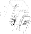
- Fig. 2 illustrates an exploded perspective view of a transmission case 20 and the HST 100A in the above transmission 10A.
- Figs. 3 to 5 illustrate an exploded perspective view, a transverse cross-sectional plan view, and a hydraulic circuit diagram of the HST 100A, respectively.
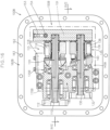
- the HST 100A includes a pump shaft 110 that operatively inputs a rotational power from a drive source 5 ( Fig. 1 ) provided in the work vehicle 1, a pump main body 115 that is relatively non-rotatably supported by the pump shaft 110, a pump-side swash plate 120 that defines a capacity of the pump main body 115, a pump-side swash plate holder 125A which supports a rear surface of the pump-side swash plate 120, a motor shaft 130, a motor main body 135 which is relatively non-rotatably supported by the motor shaft 130, a motor-side swash plate 140 which defines a capacity of the motor main body 135, a motor-side swash plate holder 145A which supports a rear surface of the motor-side swash plate 140, a center section 150A, a main plate 160A, and a sub-plate 170A.
- a pump shaft 110 that operatively inputs a rotational power from a drive source 5 ( Fig. 1 ) provided
- the HST 100A is of an in-line type in which the pump main body 115 and the motor main body 135 are arranged on one side and the other side in the thickness direction of the center section 150A, respectively, while being arranged coaxially with each other.
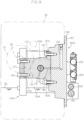
- Fig. 6 illustrates a cross-sectional view along the line VI-VI in Fig. 4 .
- the pump main body 115 has a pump-side cylinder block 116, and pump-side pistons 118 housed in the pump-side cylinder block 116 so as to be relatively non-rotatable around an axial line and to advance and retreat in an axial line direction with respect thereto.
- the pump-side cylinder block 116 is relatively non-rotatably supported by the pump shaft 110 with a base end surface directly or indirectly contacting a first end surface on one side in the thickness direction of the center section 150A.
- the pump-side swash plate 120 is engaged with tip end portions of the pump-side pistons 118 so as to define the advance or retreat amount of the pump-side pistons 118 per revolution around the axial line of the pump-side cylinder block 116, that is, the capacity of the pump main body 115.
- the pump-side swash plate 120 is a movable swash plate that can swing around the swing axial line, and according to the swing position of the pump-side swash plate 120 around the swing axial line, the advance or retreat amount of the pump-side piston 118 changes thereby to change the capacity of the pump main body 115.
- the pump-side swash plate holder 125A is arranged in a manner to support the rear surface of the pump-side swash plate 120 (a surface opposite in the axial line direction to the surface with which the pump-side piston 118 is engaged).
- the pump-side swash plate 120 is a movable swash plate that can swing around the swing axial line.
- the pump-side swash plate holder 125A has a concave support surface along the swing path of the rear surface of the pump-side swash plate 120 which path is seen when the pump-side swash plate 120 is swung around the swing axial line.
- the pump shaft 110 supports the pump main body 115 at a middle portion in a manner relatively non-rotatable around the axial line with respect to the pump shaft 110.
- the pump-side swash plate 120 is provided with a through hole that allows the pump shaft 110 to pass through.
- the motor main body 135 has a motor-side cylinder block 136 and motor-side pistons 138 housed in the motor-side cylinder block 136 so as to be relatively non-rotatable around an axial line and to advance and retreat in an axial line direction with respect thereto.
- the motor-side cylinder block 136 is supported by the motor shaft 130, which is arranged coaxially with the pump shaft 110, in a manner relatively non-rotatable around the axial line with respect to the motor shaft 130.
- the motor-side swash plate 140 is engaged with the tip end portions of the motor-side pistons 138 so as to define the advance or retreat amount of the motor-side pistons 138 per revolution around the axial line of the motor-side cylinder block 136, that is, the capacity of the motor main body 135.
- the motor-side swash plate 140 is a fixed swash plate in which a swash angle relative to the motor shaft 130 is fixed so that the capacity of the motor main body 135 is fixed.
- the motor-side swash plate holder 145A is arranged in a manner to support the rear surface of the motor-side swash plate 140 (a surface opposite in the axial line direction to the surface with which the motor-side piston 138 is engaged).
- the motor-side swash plate 140 is the fixed swash plate.
- the motor-side swash plate holder 145A has a swash support surface for fixing the motor-side swash plate 140 at a predetermined swash angle.
- the motor shaft 130 is arranged coaxially with the pump shaft 110. With the base end and the tip end portions thereof rotatably supported by the center section 150A and the motor-side swash plate holder 145A, respectively, the motor shaft 130 supports the motor main body 135 at the middle portion in a manner relatively non-rotatable manner around the axial line with respect to the motor shaft 130.
- the motor-side swash plate 140 is provided with a through hole that allows the motor shaft 130 to pass through.
- Fig. 7 illustrates a cross-sectional view along the line VII-VII in Fig. 4 .
- a pair of HST operation oil paths 151 which fluidly connects the pump main body 115 and the motor main body 135 is formed in the center section 150A.
- the main plate 160A and the sub-plate 170A are so configured as to hold or support the center section 150A, the pump-side swash plate holder 125A, and the motor-side swash plate holder 145A in a sandwiched manner by their inner surfaces facing each other.
- the main plate 160A with the inner surface thereof in contact with the side surfaces of the center section 150A, the pump-side swash plate holder 125A, and the motor-side swash plate holder 145A on one side in the width direction orthogonal to the thickness direction (that is, the axial line direction of the pump shaft 110 and the motor shaft 130), is connected to the above members by fastening members 190 (see Fig. 3 ), such as a bolt.
- the sub-plate 170A With the center section 150A, the pump-side swash plate holder 125A, and the motor-side swash plate holder 145A arranged between the inner surface of the sub-plate 170A and the inner surface of the main plate 160A, the sub-plate 170A is arranged so as to face the main plate 160A. Further, the inner surface of the sub-plate 170A is brought into contact with the side surfaces of the center section 150A, the pump-side swash plate holder 125A, and the motor-side swash plate holder 145A on the other side in the width direction, and is connected to the above members by fastening members 191 (see Fig. 3 ), such as a bolt.
- the main plate 160A when viewed along a direction in which the main plate 160A and the sub-plate 170Aface each other (i.e., a direction orthogonal to plate surfaces of the main plate 160A and the sub-plate 170A), the main plate 160Ais provided with an extended region 162 that extends farther outward in the planar direction than an installation space of the center section 150A, the pump-side swash plate holder 125A, and the motor-side swash plate holder 145A, and than the sub-plate 170A.
- the center section 150A, the pump-side swash plate holder 125A, and the motor-side swash plate holder 145A are supported at both sides by the main plate 160A and the sub-plate 170A, the support of the components can be stabilized.
- the transmission case 20 to which the HST 100A is mounted providing an opening 22 (see Fig. 2 ) that is smaller than the extended region 162 of the main plate 160A and larger than the installation space of the center section 150A, the pump-side swash plate holder 125A, and the motor-side swash plate holder 145A, and than the sub-plate 170A makes it possible to attach or detach the HST 100A to or from the transmission case 20 without disassembling the HST 100A.
- the maintenance work and component replacement work of the HST 100A can be facilitated.
- the transmission 10A is provided with the transmission case 20, an input-side transmission shaft 30 which is, in a state of being operatively connected to the drive source 5, supported by the transmission case 20 in a manner to rotate around an axial line, an input-side transmission gear 32 supported by the input-side transmission shaft 30 in a manner relatively non-rotatable around the axial line with respect to the input-side transmission shaft 30 within the transmission case 20, an output-side transmission shaft 35 supported by the transmission case 20 in a manner to rotate around an axial line, an output-side transmission gear 37 supported by the output-side transmission shaft 35 in a manner relatively non-rotatable manner around the axial line with respect to the output-side transmission shaft 35 within the transmission case 20, and the HST 100A.
- the input-side transmission gear 32 and the output-side transmission gear 37 are arranged axially spaced apart within a front half portion or a first half portion of the transmission case 20.
- the HST 100A is so configured as to be detachably attached to the transmission case 20, and so configured that when the HST 100A is mounted on the transmission case 20, the pump shaft 110 is operatively connected to the input-side transmission shaft 30 and the motor shaft 130 is operatively connected to the output-side transmission shaft 35.
- the HST 100A further has a pump-side transmission gear 112 supported by the pump shaft 110 in a manner relatively non-rotatable around the axial line with respect to the pump shaft 110 and a motor-side transmission gear 132 supported by the motor shaft 130 in a manner relatively non-rotatable around the axial line with respect to the motor shaft 130.
- the pump-side transmission gear 112 is supported at a portion of the pump shaft 110 that extends from a portion passing through the pump-side swash plate holder 125Ain a direction away from the pump main body 115
- the motor-side transmission gear 132 is supported at a portion of the motor shaft 130 that extends from a portion passing through the motor-side swash plate holder 145Ain a direction away from the motor main body 135.
- the transmission case 20 has, in the first half portion thereof, a peripheral wall 21 and the opening 22 provided in the peripheral wall 21.
- the opening 22 is so sized as to allow, in the assembled state of the HST 100A, insertion of components other than the main plate 160Ain the HST 100A.
- the opening 22 is so configured as to be larger than the installation space of the center section 150A, the pump-side swash plate holder 125A, and the motor-side swash plate holder 145A, and than the sub-plate 170A, but smaller than the extended region 162 of the main plate 160A.
- the opening 22 is provided at a side surface of the peripheral wall 21, the side surface being located on the side based on the state in which the transmission case 20 is mounted on the work vehicle 1.
- the opening 22 is also possible to provide the opening 22 at an upper surface or a lower surface of the peripheral wall 21.
- fastening holes 163 through which fastening members such as a bolt can be inserted are formed at the extended region 162 of the main plate 160A.
- the extended region 162 is brought in contact with an outer surface of the peripheral wall 21 of the transmission case 20 in a state in which the HST 100A's component other than the main plate 160A is housed within the transmission case 20 via the opening 22, and is detachably connected to the outer surface via fastening members such as a bolt to be inserted into the fastening hole 163.
- the pump-side transmission gear 112 and the motor-side transmission gear 132 are so arranged to respectively mesh with the input-side transmission gear 32 and the output-side transmission gear 37 in accordance with connection of the extended region 162 of the main plate 160A to the outer surface of the peripheral wall 21 of the transmission case 20.
- the inner surfaces of the main plate 160A and the sub-plate 170A are provided with center section-directed concave portions 165 and 175 in which the center section 150A is engaged in a manner to be immovable in the thickness direction.
- the main plate 160A and the sub-plate 170A are formed with the center section-directed concave portions 165 and 175, respectively, but it is possible that only one of the main plate 160A and the sub-plate 170A is formed with the corresponding concave portion.
- the inner surfaces of the main plate 160A and the sub-plate 170A are provided with pump-side concave portions 166 and 176 into which the pump-side swash plate holder 125A is engaged, and motor-side concave portions 167 and 177 into which the motor-side swash plate holder 145A is engaged.
- the pump-side concave portions 166, 176 and the motor-side concave portions 167, 177 are so configured as to prevent the pump-side swash plate holder 125A and the motor-side swash plate holder 145A from moving in a direction away from the center section 150A with respect to the thickness direction (axial line direction of the pump shaft 110 and the motor shaft 130).
- the pump-side concave portions 166 and 176 have step portions 166a and 176a that engage with end surfaces of the pump-side swash plate holder 125A on a far side from the center section 150A.
- the motor-side concave portions 167 and 177 have step portions 167a and 177a that engage with end surfaces of the motor-side swash plate holder 145A on a far side from the center section 150A.
- Providing such a configuration can further stabilize the support state of the HST preassembly.
- the pump-side concave portions 166, 176 and the motor-side concave portions 167, 177 can be so configured as to prevent the pump-side swash plate holder 125A and the motor-side swash plate holder 145A from moving in a direction proximate to the center section 150A with respect to the thickness direction.
- the pump-side concave portions 166 and 176 can be so configured as to have step portions that engage with the end surfaces of the pump-side swash plate holder 125A on a near side to the center section 150A
- the motor-side concave portions 167 and 177 can be so configured as to have step portions that engage with the end surfaces of the motor-side swash plate holder 145A on a near side to the center section 150A.
- the center section-directed concave portions 165, 175 have step portions 165a, 165b, 175a, 175b that engage with the lower surface and upper surface of the center section 150A.
- Figs. 8 and 9 illustrate cross-sectional views along the lines VIII-VIII and IX-IX in Fig. 4 , respectively.
- the pump-side concave portions 166 and 176 have step portions 166b, 176b, 166c, and 176c that engage with the lower surface and upper surface of the pump-side swash plate holder 125A.
- the motor-side concave portions 167 and 177 have step portions 167b, 177b, 167c, and 177c that engage with the lower surface and upper surface of the motor-side swash plate holder 145A.
- Such a configuration can further stabilize the support of the HST preassembly.
- the center section-directed concave portions 165 and 175 have step portions 165a and 175a that engage with the lower surfaces of the center section 150A and step portions 165b and 175b that engage with the upper surfaces of the center section 150A, but alternatively, can be modified in such a way as to have only the step portion that engages with any one of the lower surface and the upper surface.
- the pump-side concave portions 166 and 176 and the motor-side concave portions 167 and 177 have step portions 166b, 176b, 167b, and 177b that engage with the lower surfaces of the corresponding swash plate holder and step portions 166c, 176c, 167c, and 177c that engage with the upper surfaces of the corresponding swash plate holder, but alternatively, can be transformed in such a way as to have only the step portion that engages with any one of the lower surface and the upper surface.
- the pump-side concave portions 166 and 176 are provided in the main plate 160A and the sub-plate 170A respectively, and the motor-side concave portions 167 and 177 are provided in the main plate 160A and the sub-plate 170A respectively, it is also possible to provide the pump-side concave portion only in one of the main plate 160A and the sub-plate 170A, and/or to provide the motor-side concave portions only in one of the main plate 160A and the sub-plate 170A.
- the above HST 100A further has a hydraulic servo mechanism 200 that generates a force for swinging a movable swash plate (the pump-side swash plate 120 in the present embodiment).
- the hydraulic servo mechanism 200 is provided at the main plate 160A.
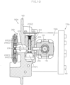
- Figs. 10 and 11 illustrate cross-sectional views along the lines X-X and XI-XI in Fig. 4 , respectively.
- the hydraulic servo mechanism 200 includes: a pushing piston 210 housed in the main plate 160A in a manner to be reciprocally movable in a direction (hereinafter, referred to as pushing direction) orthogonal to both the axial line of the hydraulic body (the pump main body 115 in the present embodiment) having the capacity varied by the movable swash plate (the pump-side swash plate 120 in the present embodiment) and the swing axial line, and is operatively connected to the movable swash plate via a connecting rod 205 so that the movable swash plate swings around the swing axial line by a movement along the pushing direction, first and second hydraulic oil chambers 215 (1) and 215 (2) formed in the main plate 160A in a manner that pressure oil supplied into the first and second hydraulic oil chambers push the pushing piston 210 to one side and the other side respectively in the pushing direction, respectively, a switching spool 220 that can selectively take: a first operation position
- the switching spool 220 is housed in an axial line hole formed in the pushing piston 210, and the direction in which the switching spool reciprocates (switch direction) and the pushing direction in which the pushing piston reciprocates are the same.
- the operating valve 250 is a solenoid valve that is operated and controlled by a control device provided in the work vehicle 1.
- a first spring 240 (1) for biasing the operating piston 230 toward the first operation position is arranged in the first operation oil chamber 235 (1)
- a second spring 240 (2) for biasing the operating piston 230 toward the second operation position is arranged in the second operation oil chamber 235 (2).
- the first and second springs 240(1), 240(2) are set to exert a biasing force in a manner to position the operating piston 230 in the hold position, when the pressure oil fails to act on both of the first and second operation oil chambers 235(1), 235(2).
- the HST 100A further has a manual operating mechanism 260 for manually moving the switching spool 220.
- connection pin 225 has a base end portion engaged with the switching spool 220 and a tip end portion engaged with the operating piston 230 so that the switching spool 220 moves along the switch direction in accordance with the movement of the operating piston 230 in the operation direction.
- the manual operating mechanism 260 is provided at the main plate 160A.
- the manual operating mechanism 260 has an operation shaft 265 supported by the main plate 160A rotatably around an axial line in a state that it is parallel to the connection pin 225 and its tip end portion extends outward, and a connection arm 270 that has a base end portion connected to the operation shaft 265 in a manner to be relatively non-rotatable around an axial line with respect thereto and has a tip end portion connected to the connection pin 225.
- Rotating the operation shaft 265 around the axial line by human operation moves the switching spool 220 in the switch direction via the connection arm 270 and the connection pin 225.
- Providing the manual operating mechanism 260 can provide a mode in which the switching spool 220 is moved by the human operation on the operation shaft 265, in addition to the mode in which the switching spool 220 is moved by the action of the hydraulic pressure via the operating valve 250.
- the position of the operating piston 230 can be controlled by the other.
- Fig. 12 is a front view of the HST 100A in a state of being mounted on the transmission case 20, as viewed from the outside of the transmission case 20.
- the part XII in Fig. 2 is illustrated in cross section.
- Fig. 13 illustrates a cross-sectional view along the line XIII-XIII in Fig. 12 .
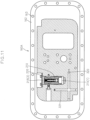
- Fig. 14 illustrates a cross-sectional view along the line XIV XIV in Fig. 4 .
- the main plate 160A has a supply oil path 310 having one end portion opened to an outer surface to form an inlet port 310P, a charge relief valve 315 that sets the hydraulic pressure of the supply oil path 310, a lubrication oil path 320 that receives a relief oil of the charge relief valve 315, and a lubrication relief valve 325 that sets the oil pressure of the lubrication oil path 320.
- the pressure oil is supplied to the inlet port 310P via a piping 305 from an auxiliary pump 9 driven by the drive source of the work vehicle 1.
- the supply oil path 310 has a downstream in the pressure oil flow direction that is branched into a charge supply oil path 311 and a servo supply oil path 312.
- the charge supply oil path 311 has a downstream side in the pressure oil flow direction opening on a contact surface with the center section 150A thereby to form a main plate side charge port 311P.
- the center section-directed concave portion 165 is formed in the main plate 160Ain which the center section 150A is engaged in a manner to be immovable in the thickness direction, and the main plate side charge port 311P is provided on the bottom surface of the center section-directed concave portion 165.
- the center section 150A is formed with, in addition to the above pair of HST operation oil paths 151, a charge oil path 153 having one end portion opened to an outer surface to form a center section side charge port 153P.
- the charge oil path 153 has a downstream side in the pressure oil flow direction branched into two directions that are respectively fluidly connected to the pair of HST operation oil paths 151 via check valves 154.
- the check valve 154 is provided with a high-pressure relief function, so that when one HST operation oil path 151 has an abnormally high pressure, the pressure oil in the one HST operation oil path 151 is relieved to the other HST operation oil path 151.
- the servo supply oil path 312 is so configured as to supply the pressure oil to the operating valve 250 and the switching spool 220.
- the transmission case 20 is capable of storing the oil in the first half portion, and an oil level OL of the transmission case 20 is set lower so as not to become a rotational resistance of the pump main body 115 and the motor main body 135 when the HST 100A is mounted on the transmission case 20.
- the lubrication oil path 320 has a pump-side lubrication oil path 321 and a motor-side lubrication oil path 322 so that forced lubrication is made for the HST 100A.
- the pump-side lubrication oil path 321 is communicated to a predetermined lubrication site such as a bearing or a piston shoe via a lubrication oil path 126 formed in the pump-side swash plate holder 125A and an axial line hole 111 formed in the pump shaft 110.
- the motor-side lubrication oil path 322 is communicated to a predetermined lubrication site such as a bearing or a piston shoe via a lubrication oil path 146 formed in the motor-side swash plate holder 145A and an axial line hole 131 formed in the motor shaft 130.
- a reference numeral 330 in Fig. 7 is a pressure oil takeout oil path having one end portion connected to the HST operation oil path 151 and the other end portion opened on the outer surface of the main plate 160A thereby to form a takeout port for measuring the pressure in the HST operation oil path 151, and a reference numeral 332 in Fig. 12 is a plug which closes the takeout port.
- the transmission 10A has a multi-step speed-change mechanism 40 that changes the rotational power of the output-side transmission shaft 35 in multiple steps, a differential mechanism 45 that differentially transmits the output of the multi-step speed-change mechanism 40 to a pair of left and right main drive axles 80, a traveling brake mechanism 50 for applying a braking force to the main drive axles 80, and a sub-drive wheel-directed power takeout mechanism 55 capable of outputting the output of the multi-step speed-change mechanism 40 to the sub-drive wheel.
- the transmission 10A further has a PTO shaft 90 capable of outputting the rotational power toward external equipment such as work equipment, a PTO transmission shaft 92 operatively connected to the input-side transmission shaft 30, a PTO brake mechanism 94 and a PTO speed-change mechanism 96 interposed in the PTO transmission path from the input-side transmission shaft 30 to the PTO shaft 90.
- the HST 100A is applicable to another transmission 10B.
- Fig. 15 illustrates a schematic diagram of power transmission of the work vehicle 1 to which the other transmission 10B provided with the above HST 100A is applied.
- the transmission 10B has a planetary gear mechanism 60, a front/rear switching mechanism 65, and a multi-step speed-change mechanism 70, in place of the multi-step speed-change mechanism 40.
- the planetary gear mechanism 60 has three planetary elements including a sun gear 61, a planetary carrier 62 and an internal gear 63, and is so configured as to synthesize the rotational power of the HST 100A input via the output-side transmission shaft 35 and the rotational power of the drive source 5 input via the input-side transmission shaft 30, and to output the synthesized rotational power.
- the rotational power of the HST 100A is input to the sun gear 61 via the output-side transmission shaft 35
- the rotational power of the drive source 5 is input to the internal gear 63 via the input-side transmission shaft 30
- the synthesized rotational power is output from the planetary carrier 62.
- Fig. 16 illustrates a vertical cross-sectional view of an HST 100B according to the present embodiment in a state of being mounted on the transmission case 20, as viewed from the inside of the transmission case 20.
- Fig. 17 illustrates a cross-sectional view along the line XVII-XVII in Fig. 16 .
- the HST 100B according to the present embodiment differs from the HST 100A according to the first embodiment in that the HST 100B is of a parallel type in which the pump main body 115 and the motor main body 135 are arranged on one side in a thickness direction of the center section 150B in a state parallel to each other.
- the HST 100B includes: a center section 150B, a pump-side swash plate holder 125B, a motor-side swash plate holder 145B, a main plate 160B and a sub-plate 170B that hold or support the center section 150B, the pump-side swash plate holder 125B, and the motor-side swash plate holder 145B in a sandwiched manner in a state where both the pump-side swash plate holder 125B and the motor-side swash plate holder 145B are arranged on one side of the center section 150B in the thickness direction, the pump shaft 110 supported rotatably around an axial line by the center section 150B and the pump-side swash plate holder 125B, the pump main body 115 supported by the pump shaft 110 in a manner relatively non-rotatable with respect to the pump shaft 110, the pump-side swash plate 120 having the rear surface supported by the pump-side swash plate holder 125B, the motor shaft 130
- the pump-side swash plate holder 125B and the motor-side swash plate holder 145B are formed by a single common swash plate holder 180.
- the HST 100B is provided with the common swash plate holder 180 integrally having a portion acting as the pump-side swash plate holder 125B and a portion acting as the motor-side swash plate holder 145B, and the main plate and the sub-plate are so configured as to hold or support the center section and the common swash plate holder in a sandwiched manner.
- the main plate 160B when viewed along the direction in which the main plate 160B and the sub-plate 170B face one another, the main plate 160B is provided with the extended region 162 that extends farther outward in the planar direction than the installation space of the center section 150B, the pump-side swash plate holder 125B, and the motor-side swash plate holder 145B (that is, the common swash plate holder 180), and than the sub-plate 170B.
- the inner surfaces of the main plate 160B and the sub-plate 170B are provided with engagement concave portions into which the common swash plate holder 180 and the center section 150B are engaged in a manner to prevent the HST preassembly from moving in the axial line direction.
- the inner surface of the main plate 160B is provided with a swash plate holder-directed concave portion 350 forming a step portion 350a that engages with an end surface of the common swash plate holder 180 that is on a far side from the center section 150B, and a center section-directed concave portion 355 forming a step 355a that engages with an end surface of the center section 150B that is on a far side from the common swash plate holder 180, as the engagement concave portions.
- the inner surface of the sub-plate 170B is provided with a swash plate holder-directed concave portion 360 forming a step portion 360a that engages with the end surface of the common swash plate holder 180 that is on the far side from the center section 150B, and a center section-directed concave portion 365 forming a step portion 365a that engages with the end surface of the center section 150B that is on the far side from the common swash plate holder 180, as the engagement concave portions.
- Providing such a configuration allows the main plate 160B and the sub-plate 170B to stabilize the supporting state of the HST preassembly.
- Fig. 18 illustrates a vertical cross-sectional view of an HST 100C according to the present embodiment in a state of being mounted on the transmission case 20, as viewed from the inside of the transmission case 20.
- the HST 100C according to the present embodiment is in common with the HST 100A according to the first embodiment in that the pump main body 115 and the motor main body 135 are respectively arranged on one side and the other side in the thickness direction of the center section 150C, but differs from the HST 100A in that the axial line positions of the pump main body 115 and the motor main body 135 are displaced from each other.
- the pump main body 115 is arranged on one side in the thickness direction of the center section 150C, while the motor main body 135 is arranged on the other side in the thickness direction of the center section 150C with the shaft line parallel to and at a different position from the shaft line of the pump main body 115.
- the HST 100C includes: a center section 150C, a pump-side swash plate holder 125C, a motor-side swash plate holder 145C, a main plate 160C and a sub-plate 170C that hold or support the center section 150C, the pump-side swash plate holder 125C, and the motor-side swash plate holder 145C in a sandwiched manner in a state where the pump-side swash plate holder 125C and the motor-side swash plate holder 145C are respectively positioned on one side and the other side in the thickness direction of the center section 150B, the pump shaft 110 supported in a rotatable manner around the axial line by the center section 150C and the pump-side swash plate holder 125C, the pump main body 115 supported by the pump shaft 110 in a manner relatively non-rotatable around the axial line with respect to the pump shaft 110, the pump-side swash plate 120 having the
- the main plate 160C when viewed along the direction in which the main plate 160C and the sub-plate 170C face one another, the main plate 160C is provided with the extended region 162 extending farther outward in the planar direction than the installation space of the center section 150C, the pump-side swash plate holder 125C, and the motor-side swash plate holder 145C, and than the sub-plate 170C.
- the inner surfaces of the main plate 160C and the sub-plate 170C are also provided with engagement concave portions into which the pump-side swash plate holder 125C, the center section 150C, and the motor-side swash plate holder 145C are engaged in a manner to prevent the HST preassembly from moving in the axial line direction.
- the engagement concave portions for the center section 150C are so formed as to have step portions that engage with the end surfaces of the center section 150C on one side and the other side in the thickness direction.
- the engagement concave portion for the pump-side swash plate holder 125C is so formed as to have a step portion that engages with an end surface of the pump-side swash plate holder 125C that is on a far side from the center section 150C.
- the engagement concave portion for the motor-side swash plate holder 145C is so formed as to have a step portion that engages with an end surface of the motor-side swash plate holder 145C that is on a far side from the center section 150C.
Landscapes
- Engineering & Computer Science (AREA)
- General Engineering & Computer Science (AREA)
- Mechanical Engineering (AREA)
- Motor Power Transmission Devices (AREA)
Claims (12)
- HST (100A-100C), umfassend eine Pumpenwelle (110), einen Pumpenhauptkörper (115), der durch die Pumpenwelle (110) in einer um eine axiale Linie in Bezug auf die Pumpenwelle (110) relativ nicht-drehbaren Weise gestützt wird, eine pumpenseitige Taumelscheibe (120), die eine Kapazität des Pumpenhauptkörpers (115) definiert, einen pumpenseitigen Taumelscheibenhalter (125A-125C), der eine rückseitige Fläche der pumpenseitigen Taumelscheibe (120) stützt, eine Motorwelle (130), einen Motorhauptkörper (135), der durch die Motorwelle (130) in einer um eine axiale Linie in Bezug auf die Motorwelle (130) relativ nicht-drehbaren Weise gestützt wird, eine motorseitige Taumelscheibe (140), die eine Kapazität des Motorhauptkörpers (135) definiert, einen motorseitigen Taumelscheibenhalter (145A-145C), der eine rückseitige Fläche der motorseitigen Taumelscheibe (140) stützt, und einen mittleren Abschnitt (150A-150C), an dem der Pumpenhauptkörper (115) und der Motorhauptkörper (135) direkt oder indirekt auf eine gleitende Weise um die jeweiligen axialen Linien anliegen und der mit Ölpfaden (151) ausgebildet ist, die den Pumpenhauptkörper (115) und den Motorhauptkörper (135) fluidisch verbinden, wobei das HST (100A-100C) dadurch gekennzeichnet ist, dassdas HST (100A-100C) eine Hauptplatte (160A-160C) und eine Nebenplatte (170A-170C) aufweist, die den mittleren Abschnitt (150A-150C), den pumpenseitigen Taumelscheibenhalter (125A-125C) und den motorseitigen Taumelscheibenhalter (145A-145C) durch einander zugewandte Innenflächen der Hauptplatte (160A-160C) und der Nebenplatte (170A-170C) zwischen sich aufnehmen und dadurch halten oder stützen,die Hauptplatte (160A-160C) mit einer erweiterten Region (162) versehen ist, die sich in einer planaren Richtung der Hauptplatte (160A-160C) weiter nach außen erstreckt als ein Installationsraum des mittleren Abschnitts (150A-150C), des pumpenseitigen Taumelscheibenhalters (125A-125C) und des motorseitigen Taumelscheibenhalters (145A-145C) und dann der Nebenplatte, entlang einer Richtung betrachtet, in der die Hauptplatte (160A-160C) und die Nebenplatte (170A-170C) einander zugewandt sind.
- HST (100A) nach Anspruch 1, wobei der Pumpenhauptkörper (115) und der Motorhauptkörper (135) auf der einen Seite bzw. der anderen Seite in einer Dickenrichtung des mittleren Abschnitts (150A) angeordnet sind, während sie koaxial zueinander angeordnet sind.
- HST (100C) nach Anspruch 1,wobei der Pumpenhauptkörper (115) auf einer Seite in der Dickenrichtung des mittleren Abschnitts (150C) angeordnet ist, undwobei der Motorhauptkörper (135) auf der anderen Seite in der Dickenrichtung des mittleren Abschnitts (150C) angeordnet ist, wobei eine Wellenlinie des Motorhauptkörpers (135) parallel zu, und versetzt von, einer Wellenlinie des Pumpenhauptkörpers (115) verläuft.
- HST (100A, 100C) nach Anspruch 2 oder 3,wobei eine Innenfläche von mindestens einer der Hauptplatte (160A, 160C) und der Nebenplatte (170A, 170C) mit einem pumpenseitigen konkaven Abschnitt (166, 176), in den der pumpenseitige Taumelscheibenhalter (125A, 125C) eingreift, und einem motorseitigen konkaven Abschnitt (167, 177), in den der motorseitige Taumelscheibenhalter (145A, 145C) eingreift, versehen ist,wobei der pumpenseitige konkave Abschnitt (166, 176) und der motorseitige konkave Abschnitt (167, 177) so eingerichtet sind, dass sie verhindern, dass der pumpenseitige Taumelscheibenhalter (125A, 125C) und der motorseitige Taumelscheibenhalter (145A, 145C) sich in einer Richtung von dem mittleren Abschnitt (150A, 150C) in Bezug auf die Dickenrichtung des mittleren Abschnitts (150A, 150C) fort oder in einer Richtung nahe zu dem mittleren Abschnitt (150A, 150C) in Bezug auf die Dickenrichtung des mittleren Abschnitts (150A, 150C) hin bewegen.
- HST (100A, 100C) nach einem der Ansprüche 2 bis 4, wobei eine Innenfläche von mindestens einer der Hauptplatte (160A, 160C) und der Nebenplatte (170A, 170C) mit einem zu dem mittleren Abschnitt hin gerichteten konkaven Abschnitt (165, 175) versehen ist, in den der mittlere Abschnitt (150A, 150C) in einer solchen Weise eingreift, dass er in der Dickenrichtung des mittleren Abschnitts (150A, 150C) unbeweglich ist.
- HST (100B) nach Anspruch 1, wobei der Pumpenhauptkörper (115) und der Motorhauptkörper (135) auf einer Seite in einer Dickenrichtung des mittleren Abschnitts (150B) angeordnet sind, wobei ihre axialen Linien parallel zueinander verlaufen.
- HST (100B) nach Anspruch 6, umfassend einen gemeinsamen Taumelscheibenhalter (180), der den pumpenseitigen Taumelscheibenhalter (125B) und den motorseitigen Taumelscheibenhalter (145B) integral aufweist.
- HST (100B) nach Anspruch 7, wobei eine Innenfläche von mindestens einer der Hauptplatte (160B) und der Nebenplatte (170B) mit einem konkaven Eingriffnahmeabschnitt (350, 355) versehen ist, in den mindestens eines der gemeinsamen Taumelscheibe (180) und des mittleren Abschnitts (150B) eingreift, um zu verhindern, dass sich eine HST-Vorbaugruppe, bei der der mittlere Abschnitt (150B), die Pumpenwelle (110), der Pumpenhauptkörper (115), die pumpenseitige Taumelscheibe (120), die Motorwelle (130), der Motorhauptkörper (135), die motorseitige Taumelscheibe (140) und der gemeinsame Taumelscheibenhalter (180) zusammengebaut sind, in der axialen Linienrichtung der Pumpenwelle (110) bewegt.
- HST (100A-100C) nach einem der Ansprüche 1 bis 8,
wobei mindestens einer des pumpenseitigen Taumelscheibenhalters (125A-125C) und des motorseitigen Taumelscheibenhalters (145A-145C) die rückseitige Fläche der entsprechenden Taumelscheibe (120, 140) in einer solchen Weise stützt, dass die entsprechende Taumelscheibe (120, 140) um eine axiale Schwenklinie schwenkbar ist, und wobei die Hauptplatte (160A-160C) mit einem hydraulischen Servomechanismus (200) versehen ist, der eine bewegliche Taumelscheibe (120), die um die entsprechende axiale Schwenklinie zwischen der pumpenseitigen Taumelscheibe (120) und der motorseitigen Taumelscheibe (140) in einer schwenkbaren Weise gestützt wird, um die entsprechende axiale Schwenklinie schwenkt. - HST (100A-100C) nach Anspruch 9,
wobei der hydraulische Servomechanismus (200) aufweist:einen Schubkolben (210), der in der Hauptplatte (160A-160C) in einer solchen Weise aufgenommen ist, dass er in einer Schubrichtung hin- und herbewegt werden kann, und über eine Verbindungsstange (205) mit der beweglichen Taumelscheibe (120) so wirkverbunden ist, dass die bewegliche Taumelscheibe (120) gemäß einer Bewegung des Schubkolbens (210) entlang der Schubrichtung um die axiale Schwenklinie schwingt, eine erste und eine zweite Hydraulikölkammer (215(1), 215(2)), die in der Hauptplatte (160A-160C) in einer solchen Weise ausgebildet sind, dass Drucköl, das in die erste und die zweite Hydraulikölkammer (215(1), 215(2)) eingeleitet wird, den Schubkolben (210) in der Schubrichtung zu der einen Seite bzw. zu der anderen Seite schiebt, einen Schaltschieber (220), der das Zuführen und Abfließen von Drucköl zu der bzw. von der ersten und der zweiten Hydraulikölkammer (215(1), 215(2)) gemäß einer Position in einer Schaltrichtung schaltet, einen Betätigungskolben (230), der in der Hauptplatte (160A-160C) in einer solchen Weise aufgenommen ist, dass er in einer Betätigungsrichtung parallel zu der Schaltrichtung hin- und herbewegt werden kann, und über einen Verbindungsstift (225) mit dem Schaltschieber (220) wirkverbunden ist, eine erste und eine zweite Betriebsölkammer (235(1), 235(2)), die in der Hauptplatte (160A-160C) in einer solchen Weise ausgebildet sind, dass Drucköl, das in die erste und die zweite Betriebsölkammer (235(1), 235(2)) eingeleitet wird, den Betätigungskolben (230) in Betätigungsrichtung zu der einen Seite und zu der anderen Seite schiebt, und ein Betätigungsventil (250), das das Zuführen und Abfließen von Drucköl zu der bzw. von der ersten und der zweiten Betriebsölkammer (235(1), 235(2)) schaltet, undwobei die Hauptplatte (160A-160C) mit einem manuellen Betätigungsmechanismus (260) versehen ist, der in der Lage ist, die Position des Schaltschiebers (220) in der Schaltrichtung manuell zu ändern. - Getriebe (10A-10C), das die Drehzahl einer Drehkraft ändert, die von einer Antriebsquelle (5) während des Betriebes angelegt wird,wobei das Getriebe (10A-10C) umfasst: ein Getriebegehäuse (20), eine antriebsseitige Getriebewelle (30), die mit der Antriebsquelle (5) wirkverbunden ist und durch das Getriebegehäuse (20) in einer um eine axiale Linie drehbaren Weise gestützt wird, ein antriebsseitiges Getriebezahnrad (32), das durch die antriebsseitige Getriebewelle (30) in einer um eine axiale Linie in Bezug auf die antriebsseitige Getriebewelle (30) innerhalb des Getriebegehäuses (20) relativ nicht-drehbaren Weise gestützt wird, eine abtriebsseitige Getriebewelle (35), die durch das Getriebegehäuse (20) in einer um eine axiale Linie drehbaren Weise gestützt wird, ein abtriebsseitiges Getriebezahnrad (37), das durch die abtriebsseitige Getriebewelle (35) in einer um eine axiale Linie in Bezug auf die abtriebsseitige Getriebewelle (35) innerhalb des Getriebegehäuses (20) relativ nicht-drehbaren Weise gestützt wird, und ein HST (10A-10C),wobei das HST (10A-10C) aufweist: eine Pumpenwelle (110), einen Pumpenhauptkörper (115), der durch die Pumpenwelle (110) in einer um eine axiale Linie in Bezug auf die Pumpenwelle (110) relativ nicht-drehbaren Weise gestützt wird, eine pumpenseitige Taumelscheibe (120), die eine Kapazität des Pumpenhauptkörpers (115) definiert, einen pumpenseitigen Taumelscheibenhalter (125A-125C), der eine rückseitige Fläche der pumpenseitigen Taumelscheibe (120) stützt und mit einem Durchgangsloch ausgebildet ist, durch das die Pumpenwelle (110) hindurchgeführt wird, ein pumpenseitiges Getriebezahnrad (112), das durch einen Abschnitt der Pumpenwelle (110) gestützt wird, der sich von einem Abschnitt, der durch den pumpenseitigen Taumelscheibenhalter (125A-125C) hindurch verläuft, in einer Richtung von dem Pumpenhauptkörper (115) fort in einer solchen Weise erstreckt, dass das pumpenseitige Getriebezahnrad (112) um die axiale Linie in Bezug auf die Pumpenwelle (110) relativ nicht-drehbar ist, eine Motorwelle (130), einen Motorhauptkörper (135), der durch die Motorwelle (130) in einer um eine axiale Linie in Bezug auf die Motorwelle (130) relativ nicht-drehbaren Weise gestützt wird, eine motorseitige Taumelscheibe (140), die eine Kapazität des Motorhauptkörpers (135) definiert, einen motorseitigen Taumelscheibenhalter (145A-145C), der eine rückseitige Fläche der motorseitigen Taumelscheibe (140) stützt und mit einem Durchgangsloch ausgebildet ist, durch das die Motorwelle (130) hindurchgeführt wird, ein motorseitiges Getriebezahnrad (132), das durch einen Abschnitt der Motorwelle (130) gestützt wird, der sich von einem Abschnitt, der durch den motorseitigen Taumelscheibenhalter (145A-145C) hindurch verläuft, in einer Richtung von dem Motorhauptkörper (135) fort in einer solchen Weise erstreckt, dass das motorseitige Getriebezahnrad (132) um die axiale Linie in Bezug auf die Motorwelle (130) relativ nicht-drehbar ist, und einen mittleren Abschnitt (150A-150C), der mit Ölpfaden (151) ausgebildet ist, die den Pumpenhauptkörper (115) und den Motorhauptkörper (135) fluidisch verbinden,wobei das Getriebe (10A-10C) dadurch gekennzeichnet ist, dassdas Getriebe (10A-10C) eine Hauptplatte (160A-160C) und eine Nebenplatte (170A-170C) aufweist, die den mittleren Abschnitt (150A-150C), den pumpenseitigen Taumelscheibenhalter (125A-125C) und den motorseitigen Taumelscheibenhalter (145A-145C) durch einander zugewandte Innenflächen der Hauptplatte (160A-160C) und der Nebenplatte (170A-170C) zwischen sich aufnehmen und dadurch halten oder stützen,das Getriebegehäuse (20) eine Umfangswand (21) und eine in der Umfangswand (21) ausgebildete Öffnung (22) aufweist,die Öffnung (22) so bemessen ist, dass sie in einem zusammengebauten Zustand des HST (100A-100C) das Einsetzen von anderen Komponenten als der Hauptplatte (160A-160C) des HST (100A-100C) gestattet,die Hauptplatte (160A-160C) abnehmbar mit einer Außenfläche der Umfangswand (21) des Getriebegehäuses (20) verbunden ist, so dass die anderen Komponenten des HST (100A-100C) außer der Hauptplatte (160A-160C) über die Öffnung (22) in das Getriebegehäuse (20) aufgenommen werden können, unddas pumpenseitige Getriebezahnrad (112) und das motorseitige Getriebezahnrad (132) sich mit dem antriebsseitigen Getriebezahnrad (32) bzw. dem abtriebsseitigen Getriebezahnrad (37) gemäß der Verbindung der Hauptplatte (160A-160C) mit der Außenfläche der Umfangswand (21) des Getriebegehäuses (20) verzahnen.
- Getriebe (10A-10C) nach Anspruch 11,wobei die Hauptplatte (160A-160C) mit einem Zufuhrölpfad (310) ausgebildet ist, der einen Endabschnitt aufweist, der zu einer Außenfläche hin geöffnet ist, um einen Einlassport (310P) zum Empfangen von Ladeöl von Betriebsöl des HST (100A-100C) zu bilden, undwobei ein Teil des Öls, das in den Zufuhrölpfad (310) eingeführt wird, über den pumpenseitigen Taumelscheibenhalter (125A-125C) in ein Axiallinienloch (111) der Pumpenwelle (110) und über den motorseitigen Taumelscheibenhalter (145A-145C) in ein Axiallinienloch (131) der Motorwelle (130) eingeleitet wird und dann über die Axiallinienlöcher (111, 131) zu den jeweiligen zu schmierenden Stellen geführt wird.
Applications Claiming Priority (2)
| Application Number | Priority Date | Filing Date | Title |
|---|---|---|---|
| JP2019108395A JP7307937B2 (ja) | 2019-06-11 | 2019-06-11 | Hst及び変速装置 |
| PCT/JP2020/022045 WO2020250790A1 (ja) | 2019-06-11 | 2020-06-04 | Hst及び変速装置 |
Publications (3)
| Publication Number | Publication Date |
|---|---|
| EP3985282A1 EP3985282A1 (de) | 2022-04-20 |
| EP3985282A4 EP3985282A4 (de) | 2023-06-28 |
| EP3985282B1 true EP3985282B1 (de) | 2024-10-16 |
Family
ID=73743969
Family Applications (1)
| Application Number | Title | Priority Date | Filing Date |
|---|---|---|---|
| EP20822517.7A Active EP3985282B1 (de) | 2019-06-11 | 2020-06-04 | Hydrostatisches getriebe und getriebevorrichtung |
Country Status (5)
| Country | Link |
|---|---|
| US (2) | US11933391B2 (de) |
| EP (1) | EP3985282B1 (de) |
| JP (1) | JP7307937B2 (de) |
| CN (1) | CN113950590B (de) |
| WO (1) | WO2020250790A1 (de) |
Families Citing this family (1)
| Publication number | Priority date | Publication date | Assignee | Title |
|---|---|---|---|---|
| US12473964B2 (en) * | 2019-06-11 | 2025-11-18 | Kanzaki Kokyukoki Mfg. Co., Ltd. | HST and transmission |
Family Cites Families (20)
| Publication number | Priority date | Publication date | Assignee | Title |
|---|---|---|---|---|
| US3810519A (en) * | 1972-03-01 | 1974-05-14 | Int Harvester Co | Vehicle transmission assembly |
| DE2633718A1 (de) * | 1976-07-27 | 1978-02-02 | Linde Ag | Hydrostatisches getriebe |
| JP2672962B2 (ja) * | 1988-02-03 | 1997-11-05 | 株式会社神崎高級工機製作所 | 車軸駆動装置 |
| JP3769030B2 (ja) * | 1993-08-10 | 2006-04-19 | 株式会社 神崎高級工機製作所 | 油圧トランスミッション |
| JPH1019106A (ja) * | 1996-07-02 | 1998-01-23 | Kubota Corp | 静油圧式無段変速装置 |
| JP3724929B2 (ja) * | 1997-09-11 | 2005-12-07 | 本田技研工業株式会社 | 斜板式油圧装置 |
| CN1085803C (zh) * | 1999-05-18 | 2002-05-29 | 徐维胜 | 双斜盘同步旋转内功率分流液压无级变速装置 |
| JP4492989B2 (ja) * | 2000-09-18 | 2010-06-30 | 株式会社 神崎高級工機製作所 | 変速操作機構 |
| JP2004027862A (ja) * | 2002-06-21 | 2004-01-29 | Honda Motor Co Ltd | 膨張機 |
| WO2004104448A1 (ja) | 2003-05-22 | 2004-12-02 | Yanmar Co., Ltd. | 静油圧式無段変速装置 |
| DE102008008236A1 (de) * | 2008-02-08 | 2009-08-13 | Markus Liebherr International Ag | Hydrostatisch leistungsverzweigtes Getriebe |
| JP5316223B2 (ja) | 2009-05-26 | 2013-10-16 | 富士電機株式会社 | 自動販売機 |
| JP5341839B2 (ja) * | 2010-08-19 | 2013-11-13 | 株式会社クボタ | トラクタの伝動装置 |
| JP5822761B2 (ja) * | 2012-03-14 | 2015-11-24 | 株式会社クボタ | コンバインの走行伝動装置 |
| JP6002901B2 (ja) * | 2012-10-04 | 2016-10-05 | 株式会社 神崎高級工機製作所 | 油圧式無段変速装置 |
| JP2016161056A (ja) * | 2015-03-03 | 2016-09-05 | 株式会社 神崎高級工機製作所 | マイクロトラクションドライブユニット及び油圧式無段変速装置 |
| CN105570421B (zh) * | 2016-01-13 | 2024-04-16 | 南通爱慕希机械股份有限公司 | 一种静液压无极变速装置 |
| CN205638889U (zh) * | 2016-04-06 | 2016-10-12 | 北京理工大学 | 一种平行轴式联体液压泵马达 |
| CN206682275U (zh) * | 2017-04-27 | 2017-11-28 | 株式会社神崎高级工机制作所 | Hmt单元 |
| CN107013407A (zh) * | 2017-06-06 | 2017-08-04 | 中国北方车辆研究所 | 一种联体液压泵马达主壳体支撑与润滑结构 |
-
2019
- 2019-06-11 JP JP2019108395A patent/JP7307937B2/ja active Active
-
2020
- 2020-06-04 EP EP20822517.7A patent/EP3985282B1/de active Active
- 2020-06-04 CN CN202080042880.2A patent/CN113950590B/zh active Active
- 2020-06-04 US US17/617,894 patent/US11933391B2/en active Active
- 2020-06-04 WO PCT/JP2020/022045 patent/WO2020250790A1/ja not_active Ceased
-
2024
- 2024-03-15 US US18/607,102 patent/US20240344601A1/en not_active Abandoned
Also Published As
| Publication number | Publication date |
|---|---|
| JP2020200890A (ja) | 2020-12-17 |
| EP3985282A1 (de) | 2022-04-20 |
| US20240344601A1 (en) | 2024-10-17 |
| US20220307578A1 (en) | 2022-09-29 |
| WO2020250790A1 (ja) | 2020-12-17 |
| CN113950590B (zh) | 2025-06-06 |
| JP7307937B2 (ja) | 2023-07-13 |
| EP3985282A4 (de) | 2023-06-28 |
| US11933391B2 (en) | 2024-03-19 |
| CN113950590A (zh) | 2022-01-18 |
Similar Documents
| Publication | Publication Date | Title |
|---|---|---|
| EP1170164B1 (de) | Achsantriebsvorrichtung | |
| US7895834B2 (en) | Hydraulic stepless transmission | |
| US6637294B2 (en) | Transmission for vehicle | |
| JPH0752666A (ja) | 油圧トランスミッション | |
| JPH0732221Y2 (ja) | 作業車両用の油圧供給装置 | |
| US20120097460A1 (en) | Hydraulically-powered working vehicle | |
| US8151927B2 (en) | Wheel motor device | |
| JP2001248728A (ja) | 車軸駆動装置 | |
| EP3985282B1 (de) | Hydrostatisches getriebe und getriebevorrichtung | |
| US7487635B2 (en) | Hydrostatic transaxle | |
| US20170307075A1 (en) | Actuator unit for controlling hydraulic pump | |
| JP4462543B2 (ja) | 油圧式無段式変速装置 | |
| US12473964B2 (en) | HST and transmission | |
| US7523610B2 (en) | Neutral valve structure | |
| JP2022156638A (ja) | 油圧・機械式無段変速装置 | |
| JP3930927B2 (ja) | ハイドロスタティックトランスミッション | |
| EP1726826A2 (de) | Hydraulische Pumpeneinheit | |
| US10890252B2 (en) | Control mechanism for stepless transmission | |
| JPH11166622A (ja) | 油圧サーボ機構のパイロット圧力制御装置 | |
| JPH0732222Y2 (ja) | 車両の走行駆動液圧回路 | |
| JPH07232568A (ja) | 作業車の油圧操作機構 | |
| JP2016038018A (ja) | 油圧式変速装置制御用アクチュエータユニット | |
| JP2001116105A (ja) | 2連ポンプユニット | |
| KR20000075949A (ko) | 차축 구동 시스템 | |
| JPH02225879A (ja) | 流体圧走行車両の走行速度切換装置 |
Legal Events
| Date | Code | Title | Description |
|---|---|---|---|
| STAA | Information on the status of an ep patent application or granted ep patent |
Free format text: STATUS: THE INTERNATIONAL PUBLICATION HAS BEEN MADE |
|
| STAA | Information on the status of an ep patent application or granted ep patent |
Free format text: STATUS: REQUEST FOR EXAMINATION WAS MADE |
|
| 17P | Request for examination filed |
Effective date: 20211214 |
|
| AK | Designated contracting states |
Kind code of ref document: A1 Designated state(s): AL AT BE BG CH CY CZ DE DK EE ES FI FR GB GR HR HU IE IS IT LI LT LU LV MC MK MT NL NO PL PT RO RS SE SI SK SM TR |
|
| PUAI | Public reference made under article 153(3) epc to a published international application that has entered the european phase |
Free format text: ORIGINAL CODE: 0009012 |
|
| DAV | Request for validation of the european patent (deleted) | ||
| DAX | Request for extension of the european patent (deleted) | ||
| A4 | Supplementary search report drawn up and despatched |
Effective date: 20230531 |
|
| RIC1 | Information provided on ipc code assigned before grant |
Ipc: F16H 57/031 20120101ALI20230524BHEP Ipc: F16H 39/14 20060101AFI20230524BHEP |
|
| GRAP | Despatch of communication of intention to grant a patent |
Free format text: ORIGINAL CODE: EPIDOSNIGR1 |
|
| STAA | Information on the status of an ep patent application or granted ep patent |
Free format text: STATUS: GRANT OF PATENT IS INTENDED |
|
| INTG | Intention to grant announced |
Effective date: 20240514 |
|
| GRAS | Grant fee paid |
Free format text: ORIGINAL CODE: EPIDOSNIGR3 |
|
| GRAA | (expected) grant |
Free format text: ORIGINAL CODE: 0009210 |
|
| STAA | Information on the status of an ep patent application or granted ep patent |
Free format text: STATUS: THE PATENT HAS BEEN GRANTED |
|
| P01 | Opt-out of the competence of the unified patent court (upc) registered |
Free format text: CASE NUMBER: APP_46152/2024 Effective date: 20240809 |
|
| AK | Designated contracting states |
Kind code of ref document: B1 Designated state(s): AL AT BE BG CH CY CZ DE DK EE ES FI FR GB GR HR HU IE IS IT LI LT LU LV MC MK MT NL NO PL PT RO RS SE SI SK SM TR |
|
| REG | Reference to a national code |
Ref country code: GB Ref legal event code: FG4D |
|
| REG | Reference to a national code |
Ref country code: CH Ref legal event code: EP Ref country code: DE Ref legal event code: R096 Ref document number: 602020039653 Country of ref document: DE |
|
| REG | Reference to a national code |
Ref country code: IE Ref legal event code: FG4D |
|
| REG | Reference to a national code |
Ref country code: LT Ref legal event code: MG9D |
|
| REG | Reference to a national code |
Ref country code: NL Ref legal event code: MP Effective date: 20241016 |
|
| REG | Reference to a national code |
Ref country code: AT Ref legal event code: MK05 Ref document number: 1733140 Country of ref document: AT Kind code of ref document: T Effective date: 20241016 |
|
| PG25 | Lapsed in a contracting state [announced via postgrant information from national office to epo] |
Ref country code: NL Free format text: LAPSE BECAUSE OF FAILURE TO SUBMIT A TRANSLATION OF THE DESCRIPTION OR TO PAY THE FEE WITHIN THE PRESCRIBED TIME-LIMIT Effective date: 20241016 |
|
| PG25 | Lapsed in a contracting state [announced via postgrant information from national office to epo] |
Ref country code: NL Free format text: LAPSE BECAUSE OF FAILURE TO SUBMIT A TRANSLATION OF THE DESCRIPTION OR TO PAY THE FEE WITHIN THE PRESCRIBED TIME-LIMIT Effective date: 20241016 |
|
| PG25 | Lapsed in a contracting state [announced via postgrant information from national office to epo] |
Ref country code: HR Free format text: LAPSE BECAUSE OF FAILURE TO SUBMIT A TRANSLATION OF THE DESCRIPTION OR TO PAY THE FEE WITHIN THE PRESCRIBED TIME-LIMIT Effective date: 20241016 Ref country code: PT Free format text: LAPSE BECAUSE OF FAILURE TO SUBMIT A TRANSLATION OF THE DESCRIPTION OR TO PAY THE FEE WITHIN THE PRESCRIBED TIME-LIMIT Effective date: 20250217 Ref country code: IS Free format text: LAPSE BECAUSE OF FAILURE TO SUBMIT A TRANSLATION OF THE DESCRIPTION OR TO PAY THE FEE WITHIN THE PRESCRIBED TIME-LIMIT Effective date: 20250216 |
|
| PG25 | Lapsed in a contracting state [announced via postgrant information from national office to epo] |
Ref country code: FI Free format text: LAPSE BECAUSE OF FAILURE TO SUBMIT A TRANSLATION OF THE DESCRIPTION OR TO PAY THE FEE WITHIN THE PRESCRIBED TIME-LIMIT Effective date: 20241016 |
|
| PG25 | Lapsed in a contracting state [announced via postgrant information from national office to epo] |
Ref country code: BG Free format text: LAPSE BECAUSE OF FAILURE TO SUBMIT A TRANSLATION OF THE DESCRIPTION OR TO PAY THE FEE WITHIN THE PRESCRIBED TIME-LIMIT Effective date: 20241016 |
|
| PG25 | Lapsed in a contracting state [announced via postgrant information from national office to epo] |
Ref country code: ES Free format text: LAPSE BECAUSE OF FAILURE TO SUBMIT A TRANSLATION OF THE DESCRIPTION OR TO PAY THE FEE WITHIN THE PRESCRIBED TIME-LIMIT Effective date: 20241016 |
|
| PG25 | Lapsed in a contracting state [announced via postgrant information from national office to epo] |
Ref country code: NO Free format text: LAPSE BECAUSE OF FAILURE TO SUBMIT A TRANSLATION OF THE DESCRIPTION OR TO PAY THE FEE WITHIN THE PRESCRIBED TIME-LIMIT Effective date: 20250116 |
|
| PG25 | Lapsed in a contracting state [announced via postgrant information from national office to epo] |
Ref country code: AT Free format text: LAPSE BECAUSE OF FAILURE TO SUBMIT A TRANSLATION OF THE DESCRIPTION OR TO PAY THE FEE WITHIN THE PRESCRIBED TIME-LIMIT Effective date: 20241016 Ref country code: LV Free format text: LAPSE BECAUSE OF FAILURE TO SUBMIT A TRANSLATION OF THE DESCRIPTION OR TO PAY THE FEE WITHIN THE PRESCRIBED TIME-LIMIT Effective date: 20241016 Ref country code: GR Free format text: LAPSE BECAUSE OF FAILURE TO SUBMIT A TRANSLATION OF THE DESCRIPTION OR TO PAY THE FEE WITHIN THE PRESCRIBED TIME-LIMIT Effective date: 20250117 |
|
| PG25 | Lapsed in a contracting state [announced via postgrant information from national office to epo] |
Ref country code: PL Free format text: LAPSE BECAUSE OF FAILURE TO SUBMIT A TRANSLATION OF THE DESCRIPTION OR TO PAY THE FEE WITHIN THE PRESCRIBED TIME-LIMIT Effective date: 20241016 |
|
| PG25 | Lapsed in a contracting state [announced via postgrant information from national office to epo] |
Ref country code: RS Free format text: LAPSE BECAUSE OF FAILURE TO SUBMIT A TRANSLATION OF THE DESCRIPTION OR TO PAY THE FEE WITHIN THE PRESCRIBED TIME-LIMIT Effective date: 20250116 |
|
| PG25 | Lapsed in a contracting state [announced via postgrant information from national office to epo] |
Ref country code: SM Free format text: LAPSE BECAUSE OF FAILURE TO SUBMIT A TRANSLATION OF THE DESCRIPTION OR TO PAY THE FEE WITHIN THE PRESCRIBED TIME-LIMIT Effective date: 20241016 |
|
| PGFP | Annual fee paid to national office [announced via postgrant information from national office to epo] |
Ref country code: DE Payment date: 20250618 Year of fee payment: 6 |
|
| PG25 | Lapsed in a contracting state [announced via postgrant information from national office to epo] |
Ref country code: DK Free format text: LAPSE BECAUSE OF FAILURE TO SUBMIT A TRANSLATION OF THE DESCRIPTION OR TO PAY THE FEE WITHIN THE PRESCRIBED TIME-LIMIT Effective date: 20241016 |
|
| REG | Reference to a national code |
Ref country code: DE Ref legal event code: R097 Ref document number: 602020039653 Country of ref document: DE |
|
| PG25 | Lapsed in a contracting state [announced via postgrant information from national office to epo] |
Ref country code: EE Free format text: LAPSE BECAUSE OF FAILURE TO SUBMIT A TRANSLATION OF THE DESCRIPTION OR TO PAY THE FEE WITHIN THE PRESCRIBED TIME-LIMIT Effective date: 20241016 |
|
| PGFP | Annual fee paid to national office [announced via postgrant information from national office to epo] |
Ref country code: FR Payment date: 20250627 Year of fee payment: 6 |
|
| PG25 | Lapsed in a contracting state [announced via postgrant information from national office to epo] |
Ref country code: RO Free format text: LAPSE BECAUSE OF FAILURE TO SUBMIT A TRANSLATION OF THE DESCRIPTION OR TO PAY THE FEE WITHIN THE PRESCRIBED TIME-LIMIT Effective date: 20241016 |
|
| PG25 | Lapsed in a contracting state [announced via postgrant information from national office to epo] |
Ref country code: SK Free format text: LAPSE BECAUSE OF FAILURE TO SUBMIT A TRANSLATION OF THE DESCRIPTION OR TO PAY THE FEE WITHIN THE PRESCRIBED TIME-LIMIT Effective date: 20241016 |
|
| PG25 | Lapsed in a contracting state [announced via postgrant information from national office to epo] |
Ref country code: CZ Free format text: LAPSE BECAUSE OF FAILURE TO SUBMIT A TRANSLATION OF THE DESCRIPTION OR TO PAY THE FEE WITHIN THE PRESCRIBED TIME-LIMIT Effective date: 20241016 |
|
| PLBE | No opposition filed within time limit |
Free format text: ORIGINAL CODE: 0009261 |
|
| STAA | Information on the status of an ep patent application or granted ep patent |
Free format text: STATUS: NO OPPOSITION FILED WITHIN TIME LIMIT |
|
| PG25 | Lapsed in a contracting state [announced via postgrant information from national office to epo] |
Ref country code: SE Free format text: LAPSE BECAUSE OF FAILURE TO SUBMIT A TRANSLATION OF THE DESCRIPTION OR TO PAY THE FEE WITHIN THE PRESCRIBED TIME-LIMIT Effective date: 20241016 |
|
| 26N | No opposition filed |
Effective date: 20250717 |
|
| PGFP | Annual fee paid to national office [announced via postgrant information from national office to epo] |
Ref country code: IT Payment date: 20250624 Year of fee payment: 6 |
|
| REG | Reference to a national code |
Ref country code: CH Ref legal event code: H13 Free format text: ST27 STATUS EVENT CODE: U-0-0-H10-H13 (AS PROVIDED BY THE NATIONAL OFFICE) Effective date: 20260127 |
|
| PG25 | Lapsed in a contracting state [announced via postgrant information from national office to epo] |
Ref country code: MC Free format text: LAPSE BECAUSE OF FAILURE TO SUBMIT A TRANSLATION OF THE DESCRIPTION OR TO PAY THE FEE WITHIN THE PRESCRIBED TIME-LIMIT Effective date: 20241016 |
|
| PG25 | Lapsed in a contracting state [announced via postgrant information from national office to epo] |
Ref country code: LU Free format text: LAPSE BECAUSE OF NON-PAYMENT OF DUE FEES Effective date: 20250604 |
|
| GBPC | Gb: european patent ceased through non-payment of renewal fee |
Effective date: 20250604 |
|
| REG | Reference to a national code |
Ref country code: BE Ref legal event code: MM Effective date: 20250630 |
|
| PG25 | Lapsed in a contracting state [announced via postgrant information from national office to epo] |
Ref country code: GB Free format text: LAPSE BECAUSE OF NON-PAYMENT OF DUE FEES Effective date: 20250604 |
|
| PG25 | Lapsed in a contracting state [announced via postgrant information from national office to epo] |
Ref country code: IE Free format text: LAPSE BECAUSE OF NON-PAYMENT OF DUE FEES Effective date: 20250604 |
|
| PG25 | Lapsed in a contracting state [announced via postgrant information from national office to epo] |
Ref country code: BE Free format text: LAPSE BECAUSE OF NON-PAYMENT OF DUE FEES Effective date: 20250630 |
|
| PG25 | Lapsed in a contracting state [announced via postgrant information from national office to epo] |
Ref country code: CH Free format text: LAPSE BECAUSE OF NON-PAYMENT OF DUE FEES Effective date: 20250630 |