EP3976385B1 - Flüssigkeitsausstossvorrichtung, flüssigkeitsausstossverfahren und aufzeichnungsmedium - Google Patents
Flüssigkeitsausstossvorrichtung, flüssigkeitsausstossverfahren und aufzeichnungsmedium Download PDFInfo
- Publication number
- EP3976385B1 EP3976385B1 EP20730488.2A EP20730488A EP3976385B1 EP 3976385 B1 EP3976385 B1 EP 3976385B1 EP 20730488 A EP20730488 A EP 20730488A EP 3976385 B1 EP3976385 B1 EP 3976385B1
- Authority
- EP
- European Patent Office
- Prior art keywords
- line feed
- head
- spot color
- feed direction
- heads
- Prior art date
- Legal status (The legal status is an assumption and is not a legal conclusion. Google has not performed a legal analysis and makes no representation as to the accuracy of the status listed.)
- Active
Links
Images






Classifications
-
- B—PERFORMING OPERATIONS; TRANSPORTING
- B41—PRINTING; LINING MACHINES; TYPEWRITERS; STAMPS
- B41J—TYPEWRITERS; SELECTIVE PRINTING MECHANISMS, i.e. MECHANISMS PRINTING OTHERWISE THAN FROM A FORME; CORRECTION OF TYPOGRAPHICAL ERRORS
- B41J2/00—Typewriters or selective printing mechanisms characterised by the printing or marking process for which they are designed
- B41J2/005—Typewriters or selective printing mechanisms characterised by the printing or marking process for which they are designed characterised by bringing liquid or particles selectively into contact with a printing material
- B41J2/01—Ink jet
- B41J2/21—Ink jet for multi-colour printing
- B41J2/2121—Ink jet for multi-colour printing characterised by dot size, e.g. combinations of printed dots of different diameter
-
- B—PERFORMING OPERATIONS; TRANSPORTING
- B41—PRINTING; LINING MACHINES; TYPEWRITERS; STAMPS
- B41J—TYPEWRITERS; SELECTIVE PRINTING MECHANISMS, i.e. MECHANISMS PRINTING OTHERWISE THAN FROM A FORME; CORRECTION OF TYPOGRAPHICAL ERRORS
- B41J2/00—Typewriters or selective printing mechanisms characterised by the printing or marking process for which they are designed
- B41J2/005—Typewriters or selective printing mechanisms characterised by the printing or marking process for which they are designed characterised by bringing liquid or particles selectively into contact with a printing material
- B41J2/01—Ink jet
- B41J2/21—Ink jet for multi-colour printing
- B41J2/2132—Print quality control characterised by dot disposition, e.g. for reducing white stripes or banding
-
- B—PERFORMING OPERATIONS; TRANSPORTING
- B41—PRINTING; LINING MACHINES; TYPEWRITERS; STAMPS
- B41J—TYPEWRITERS; SELECTIVE PRINTING MECHANISMS, i.e. MECHANISMS PRINTING OTHERWISE THAN FROM A FORME; CORRECTION OF TYPOGRAPHICAL ERRORS
- B41J19/00—Character- or line-spacing mechanisms
- B41J19/14—Character- or line-spacing mechanisms with means for effecting line or character spacing in either direction
- B41J19/142—Character- or line-spacing mechanisms with means for effecting line or character spacing in either direction with a reciprocating print head printing in both directions across the paper width
-
- B—PERFORMING OPERATIONS; TRANSPORTING
- B41—PRINTING; LINING MACHINES; TYPEWRITERS; STAMPS
- B41J—TYPEWRITERS; SELECTIVE PRINTING MECHANISMS, i.e. MECHANISMS PRINTING OTHERWISE THAN FROM A FORME; CORRECTION OF TYPOGRAPHICAL ERRORS
- B41J2/00—Typewriters or selective printing mechanisms characterised by the printing or marking process for which they are designed
- B41J2/005—Typewriters or selective printing mechanisms characterised by the printing or marking process for which they are designed characterised by bringing liquid or particles selectively into contact with a printing material
- B41J2/01—Ink jet
- B41J2/015—Ink jet characterised by the jet generation process
- B41J2/04—Ink jet characterised by the jet generation process generating single droplets or particles on demand
- B41J2/045—Ink jet characterised by the jet generation process generating single droplets or particles on demand by pressure, e.g. electromechanical transducers
- B41J2/04501—Control methods or devices therefor, e.g. driver circuits, control circuits
- B41J2/0451—Control methods or devices therefor, e.g. driver circuits, control circuits for detecting failure, e.g. clogging, malfunctioning actuator
-
- B—PERFORMING OPERATIONS; TRANSPORTING
- B41—PRINTING; LINING MACHINES; TYPEWRITERS; STAMPS
- B41J—TYPEWRITERS; SELECTIVE PRINTING MECHANISMS, i.e. MECHANISMS PRINTING OTHERWISE THAN FROM A FORME; CORRECTION OF TYPOGRAPHICAL ERRORS
- B41J2/00—Typewriters or selective printing mechanisms characterised by the printing or marking process for which they are designed
- B41J2/005—Typewriters or selective printing mechanisms characterised by the printing or marking process for which they are designed characterised by bringing liquid or particles selectively into contact with a printing material
- B41J2/01—Ink jet
- B41J2/015—Ink jet characterised by the jet generation process
- B41J2/04—Ink jet characterised by the jet generation process generating single droplets or particles on demand
- B41J2/045—Ink jet characterised by the jet generation process generating single droplets or particles on demand by pressure, e.g. electromechanical transducers
- B41J2/04501—Control methods or devices therefor, e.g. driver circuits, control circuits
- B41J2/04551—Control methods or devices therefor, e.g. driver circuits, control circuits using several operating modes
-
- B—PERFORMING OPERATIONS; TRANSPORTING
- B41—PRINTING; LINING MACHINES; TYPEWRITERS; STAMPS
- B41J—TYPEWRITERS; SELECTIVE PRINTING MECHANISMS, i.e. MECHANISMS PRINTING OTHERWISE THAN FROM A FORME; CORRECTION OF TYPOGRAPHICAL ERRORS
- B41J2/00—Typewriters or selective printing mechanisms characterised by the printing or marking process for which they are designed
- B41J2/005—Typewriters or selective printing mechanisms characterised by the printing or marking process for which they are designed characterised by bringing liquid or particles selectively into contact with a printing material
- B41J2/01—Ink jet
- B41J2/135—Nozzles
- B41J2/145—Arrangement thereof
- B41J2/155—Arrangement thereof for line printing
-
- B—PERFORMING OPERATIONS; TRANSPORTING
- B41—PRINTING; LINING MACHINES; TYPEWRITERS; STAMPS
- B41J—TYPEWRITERS; SELECTIVE PRINTING MECHANISMS, i.e. MECHANISMS PRINTING OTHERWISE THAN FROM A FORME; CORRECTION OF TYPOGRAPHICAL ERRORS
- B41J2/00—Typewriters or selective printing mechanisms characterised by the printing or marking process for which they are designed
- B41J2/005—Typewriters or selective printing mechanisms characterised by the printing or marking process for which they are designed characterised by bringing liquid or particles selectively into contact with a printing material
- B41J2/01—Ink jet
- B41J2/21—Ink jet for multi-colour printing
- B41J2/2107—Ink jet for multi-colour printing characterised by the ink properties
- B41J2/2114—Ejecting specialized liquids, e.g. transparent or processing liquids
- B41J2/2117—Ejecting white liquids
-
- B—PERFORMING OPERATIONS; TRANSPORTING
- B41—PRINTING; LINING MACHINES; TYPEWRITERS; STAMPS
- B41J—TYPEWRITERS; SELECTIVE PRINTING MECHANISMS, i.e. MECHANISMS PRINTING OTHERWISE THAN FROM A FORME; CORRECTION OF TYPOGRAPHICAL ERRORS
- B41J2/00—Typewriters or selective printing mechanisms characterised by the printing or marking process for which they are designed
- B41J2/485—Typewriters or selective printing mechanisms characterised by the printing or marking process for which they are designed characterised by the process of building-up characters or image elements applicable to two or more kinds of printing or marking processes
- B41J2/505—Typewriters or selective printing mechanisms characterised by the printing or marking process for which they are designed characterised by the process of building-up characters or image elements applicable to two or more kinds of printing or marking processes from an assembly of identical printing elements
- B41J2/51—Typewriters or selective printing mechanisms characterised by the printing or marking process for which they are designed characterised by the process of building-up characters or image elements applicable to two or more kinds of printing or marking processes from an assembly of identical printing elements serial printer type
Definitions
- Embodiments of the present invention relate to a liquid discharge apparatus, a liquid discharge method, and a recording medium.
- liquid discharge apparatus that discharges an ink (liquid) from a head and forms an image (or performs modeling) on a medium.
- ink liquid
- image or performs modeling
- a liquid discharge apparatus before printing is performed on a transparent medium, printing with a white ink is performed as a base of a color image.
- This printing method is referred to as "front printing".
- the front printing can prevent light from passing through a transparent medium due to the white ink, and therefore can achieve a vivid color expression.
- a white ink may be printed.
- This printing method is referred to as "back printing” and can improve durability against rubbing due to friction on a printing surface.
- a printing effect can be enhanced.
- UV inkjet printer uses a UV ink that is cured by being irradiated with ultraviolet light (hereinafter, referred to as UV light).
- the UV inkjet printer can instantaneously cure the ink by irradiating the ink with UV light after discharging the ink. For this reason, there is little permeation or bleeding of the ink into a recording medium, and printing can be performed not only on plain paper but also on various media such as a film-shaped packaging material, a plate-shaped plastic, an acrylic base material, metal, and glass.
- UV inkjet printer for example, as disclosed in PTL 1 ( JP-2003-285427-A ), a system including a plurality of white heads and process color heads for performing front printing and back printing has been proposed.
- the present invention has been achieved in view of the above-described problems, and an object of the present invention is to provide a liquid discharge apparatus, a liquid discharge method, and a liquid discharge program capable of achieving both high productivity (high-speed printing) and high image quality.
- a liquid discharge apparatus, a liquid discharge method for a liquid discharge apparatus and a recording medium storing a liquid discharge program of a liquid discharge apparatus are provided as defined in the appended claims.
- the present invention exhibits an effect that both high productivity (high-speed printing) and high image quality can be achieved.
- liquid discharge apparatus that discharges an ink (liquid) from a head to form an image on a medium.
- the present invention is also applicable to a three-dimensional modeling apparatus that performs modeling on a medium.
- Fig. 1 is a perspective view of a liquid discharge apparatus according to a first embodiment.
- Fig. 2 is a top view of the liquid discharge apparatus according to the first embodiment.
- the liquid discharge apparatus 1 includes a support stage 20 having a stage surface 20a on which a print target 10 is placed.
- the stage surface 20a of the support stage 20 on which the print target 10 is placed is constituted by an attraction table 21.
- An attraction mechanism disposed in a structure 22 generates an attraction force on a surface of the attraction table 21, and attracts the placed print target 10 to the stage surface 20a.
- the print target 10 may be attracted to the stage surface 20a by, for example, electrostatic attraction.
- the liquid discharge apparatus 1 includes a gantry 50 supporting a carriage 200 such that the carriage 200 can reciprocate in a first direction X (main scanning direction) with respect to the stage surface 20a of the support stage 20.
- the gantry 50 is disposed so as to be able to reciprocate (relatively move) in a second direction Y (sub-scanning direction) orthogonal to the first direction with respect to the stage surface 20a of the support stage 20.
- the movement of the gantry 50 in the Y direction is controlled by reading sub-scanning encoder sheets 23 arranged on both sides of the support stage 20 with a sub-scanning encoder sensor disposed in the gantry 50.
- both side plates 51 and 51 each include four sets of height detection sensors (thickness measurement sensors) 60 (60A to 60D) including a light emitting unit 61 and a light receiving unit 62, the height detection sensors being arranged facing each other with the stage surface 20a of the support stage 20 interposed therebetween.
- the height detection sensors 60A and 60C are arranged at a height different from the height of the height detection sensors 60B and 60D.
- the height detection sensor 60 can detect presence or absence of the print target 10 across the support stage 20 in the first direction, and can detect presence or absence of the print target 10 in the entire area of the stage surface 20a of the support stage 20 in the first direction.
- the gantry 50 is disposed so as to be able to move (rise and fall) in the height direction (Z direction), and the height detection sensor 60 raises and lowers the gantry 50 to adjust the height of the attraction table 21 of the support stage 20 in the Z direction.
- the height detection sensor 60 also serves as a human sensor.
- the height detection sensor 60 may adjust the height.
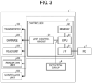
- FIG. 3 is a block diagram illustrating a hardware configuration of the liquid discharge apparatus according to the first embodiment.
- Fig. 4 is a front view of the liquid discharge apparatus.
- Fig. 5 is a plan view of the liquid discharge apparatus.
- the liquid discharge apparatus 1 includes a controller unit 3, a detection group 4, a transport unit 100 which is a transporter, the carriage 200, a head unit 300, an irradiation unit 400, and a maintenance unit 500.
- the controller unit 3 includes a unit control circuit 31, a memory 32 that stores various types of data, a central processing unit (CPU) 33 which is a control main body, and an interface (I/F) 34.
- CPU central processing unit
- I/F interface
- the unit control circuit 31 controls an operation of each of the units (transport unit 100, carriage 200, head unit 300, irradiation unit 400, and maintenance unit 500) of the liquid discharge apparatus 1 according to an instruction from the CPU 33.
- the I/F 34 is an interface for connecting the liquid discharge apparatus 1 to an external personal computer (PC) 2.
- PC personal computer
- the liquid discharge apparatus 1 and the PC 2 can be connected to each other via a network or directly by a communication cable.
- Examples of the detection group 4 include various sensors included in the liquid discharge apparatus 1, such as a height sensor 41 illustrated in Figs. 2 and 3 .
- the memory 32 stores various programs or data executable by the CPU 33.
- examples of the memory 32 include a semiconductor memory such as a read only memory (ROM) or a random access memory (RAM), and an optical, magnetic, and electric recording media such as a hard disk, a compact disc (CD)-ROM, and a digital versatile disk (DVD)-ROM.
- the memory 32 stores a liquid discharge program described later.
- Various programs executed by the liquid discharge apparatus 1 can be provided by being recorded on a computer-readable recording medium such as a CD-ROM, a flexible disk (FD), a CD-R, a DVD, or a Blu-ray (registered trademark) disk in an installable format or an executable format.
- a computer-readable recording medium such as a CD-ROM, a flexible disk (FD), a CD-R, a DVD, or a Blu-ray (registered trademark) disk in an installable format or an executable format.
- Various programs executed by the liquid discharge apparatus 1 may be provided by being stored on a computer connected to a network such as the Internet and downloaded via the network. Various programs executed by the liquid discharge apparatus 1 may be provided or distributed via a network such as the Internet.
- the recording data includes command data for operating the transport unit 100 and the like of the liquid discharge apparatus 1 and pixel data relating to an image (liquid application surface 102).
- the pixel data includes 2-bit data for each pixel, and can be expressed in four gradations.
- the transport unit 100 includes a stage 130 and an attraction mechanism 120.
- the attraction mechanism 120 has a plurality of attraction holes 100a formed in a fan 110 and the stage 130.
- the attraction mechanism 120 drives the fan 110 and attracts the base material 101 from the attraction holes 100a to temporarily secure the base material 101 to the transport unit 100.
- the attraction mechanism 120 may attract a sheet using electrostatic attraction.
- the transport unit 100 moves in the Y-axis direction (sub-scanning direction Y) under control based on a drive signal from the CPU 33 via the unit control circuit 31.
- the transport unit 100 includes a transport controller 210, a roller 105, and a motor 104.
- the transport controller 210 drives the motor 104 and rotates the roller 105 to move the base material 101 in the Y-axis direction (sub-scanning direction Y).
- the transport unit 100 may move the carriage 200 instead of the base material 101 in the Y-axis direction (sub-scanning direction Y). That is, the transport unit 100 relatively moves the base material 101 and the carriage 200 in the Y-axis direction (sub-scanning direction Y).
- the transport unit 100 includes a side plate 407b supporting two guides 201 that guide the carriage 200 in the X-axis direction (main scanning direction X), a table 406 supporting the side plate 407b, a belt 404 secured to the table 406, a driving pulley 403 and a driven pulley 402 between which the belt 404 is stretched, and a motor 405 that rotates and drives the driving pulley 403.
- the transport unit 100 includes a side plate 407a supporting the two guides 201 that guide the carriage 200 in the X-axis direction (main scanning direction X), a table 408 slidably supporting the side plate 407a, and a groove 409 that is formed on the table 408 and guides the side plate 407a in the sub-scanning direction Y.
- the transport unit 100 drives the motor 405 with the transport controller 210 to rotate the driving pulley 403 and to move the belt 404 in the Y-axis direction (sub-scanning direction Y).
- the carriage 200 can be moved in the Y-axis direction (sub-scanning direction Y).
- the side plate 407a moves in the Y-axis direction (sub-scanning direction Y) along the groove 409 of the table 408 along with movement of the table 406 in the Y-axis direction (sub-scanning direction Y).
- Movement of the carriage 200 in the Z-axis direction (height direction Z) and the X-axis direction (main scanning direction X) is controlled based on a drive signal from the CPU 33 (unit control circuit 31).
- a scanner 206 includes a driving pulley 203, a driven pulley 204, a driving belt 202, and a motor 205.
- the carriage 200 is secured to the driving belt 202 stretched between the driving pulley 203 and the driven pulley 204.
- the guide 201 is supported by side plates 211A and 211B of the apparatus main body.
- a height adjuster 207 includes a motor 209 and a slider 208. The height adjuster 207 drives the motor 209 and moves the slider 208 up and down to move the guide 201 up and down.
- the head unit 300 is disposed on a lower surface of the carriage 200.
- the head unit 300 includes heads that discharge black (300K), cyan (300C), magenta (300M), yellow (300Y), and white (300W) UV curable inks, respectively.
- Each of the heads of the head unit 300 includes a piezo element (piezoelectric element).
- the piezo element performs a contraction movement in response to a drive signal supplied from the CPU 33 (unit control circuit 31). As a result, a pressure changes due to the contraction movement, the UV curable ink is discharged onto the base material 101, and the liquid application surface 102 is formed on the base material 101.
- examples of the UV curable ink include an ink containing a methacrylate-based monomer.
- the methacrylate-based monomer has weak skin sensitization to irritate the skin due to an excessive immune reaction by a chemical substance advantageously.
- Fig. 6 is a diagram illustrating a configuration of the head unit 300 and the irradiation unit 400.
- the head unit 300 includes, for example, a total of 12 heads.
- three heads (300W1, 300W2, and 300W3) arranged on the left side and three heads (300W4, 300W5, and 300W6) arranged on the right side are heads for white (for W).
- the three heads 300W1 to 300W3 arranged on the left side are arranged so as to be continuous in a stepwise manner in the sub-scanning direction (line feed direction), and arranged so as to form a linear white pixel in the sub-scanning direction without interruption of white pixels for the three heads.
- the three heads 300W4 to 300W6 arranged on the right side are arranged so as to be continuous in a stepwise manner in the sub-scanning direction, and arranged so as to form a linear white pixel in the sub-scanning direction without interruption of white pixels for the three heads.
- Each of the heads 300W1 to 300W6 includes four nozzles.
- the three heads 300CM1 to 300CM3 arranged at the center are cyan and magenta heads.
- Each of the heads 300CM1 to 300CM3 includes four nozzle rows. Of these nozzle rows, two nozzle rows corresponding to each of 300C1 to 300C3 are cyan nozzles, and similarly, two nozzle rows corresponding to each of 300M1 to 300M3 are magenta nozzles.
- the three heads 300YK1 to 300YK3 arranged at the center are yellow and black heads.
- Each of the heads 300YK1 to 300YK3 includes four nozzles rows. Of these nozzle rows, two nozzle rows corresponding to each of 300K1 to 300K3 are yellow nozzles, and similarly, two nozzle rows corresponding to each of 300K1 to 300K3 are black nozzles.
- the irradiation unit 400 includes UV irradiation devices 401 and 402 that emit UV light.
- the UV irradiation devices 401 and 402 are disposed on side surfaces (surfaces in the X-axis direction (main scanning direction X)) of the carriage 200, respectively.
- the UV irradiation devices 401 and 402 of the irradiation unit 400 emit UV light based on a drive signal from the CPU 33 (unit control circuit 31).
- the transport unit 100 moves in the Y-axis direction (sub-scanning direction Y) based on a drive signal from the CPU 33, and positions the base material 101 at an initial position for forming an image (liquid application surface 102).
- the CPU 33 moves the carriage 200 to a height suitable for discharging a UV curable ink by the head unit 300 (for example, a height at which a head gap between the head unit 300 and the base material 101 is 1 mm). Note that the CPU 33 monitors the height of the head unit 300 based on a detection signal from the height sensor 41
- the CPU 33 reciprocates the carriage 200 in the X-axis direction (main scanning direction X). At the time of this reciprocation, the CPU 33 controls the driving of the head unit 300 so as to discharge a UV curable ink. As a result, an image for one scan (liquid application surface 102) is formed on the base material 101.
- the CPU 33 controls movement of the transport unit 100 for one scan in the Y-axis direction (sub-scanning direction Y).
- the moving operation in the Y-axis direction is called “line feed”
- the number of times of the scan operations differs depending on the resolution in the Y-axis direction.
- line feed amount In a case of low resolution, since the number of scans is small (line feed amount is large), high-speed printing (high production) can be performed.
- high-speed printing high production
- high-speed printing since the number of scans is large (line feed amount is small), it is difficult to perform high-speed printing, but high image quality can be achieved.
- a UV curable ink is leveled (smoothed), and UV light is emitted from the irradiation unit 400 to cure the UV curable ink.
- Irradiation with UV light by the irradiation unit 400 is performed when the carriage 200 is moved to a height suitable for discharging the UV curable ink by the head unit 300 and reciprocates in the X-axis direction (main scanning direction X).
- the head unit 300 includes six process color heads (cyan, magenta, yellow, and black) at the center, and six white heads 300W1 to 300W6 on the left and right.
- white heads arranged on the left and right are used.
- the three rows of white heads one or two rows are used.
- the white head is disposed as a spot color head, but a spot color head of another spot color such as a clear color or a metallic color may be disposed.
- Fig. 7 is an example of front printing using two rows of white heads.
- the term "two rows” means that two rows are used among the three rows of heads arranged in the sub-scanning direction
- the carriage reciprocates.
- the white heads 300W1 and 300W4 discharge a white ink to form a white base.
- the white heads 300W2 and 300W5 and the process color heads 300CM2 and 300YK2 reach a print area
- the white heads 300W2 and 300W5 discharge a white ink and superimpose a white ink layer to complete the white base.
- the process color heads 300CM2 and 300YK2 discharge no color ink.
- the white heads 300W1 and 300W2 arranged on the left side are used, and the white heads 300W4 and 300W5 arranged on the right side are used. Therefore, a head having a nozzle length of Y1 is used.
- Formation of the white base is completed, and the carriage 200 is moved by line feed in the Y-axis direction. Thereafter, when the white head 300W3, the process color head 300CM3, the process color head 300YK3, and the white head 300W6 reach a print area, the process color heads 300CM3 and 300YK3 superimpose a color image to form a final image. At this time, the white heads 300W3 and 300W6 discharge no white ink.
- Fig. 8 is an example of front printing using one row of white heads.
- the term "one row” means that one row is used among the three rows of heads arranged in the sub-scanning direction.
- the white head 300W1, the process color head 300CM1, the process color head 300YK1, and the white head 300W4 reach a print area, reciprocation of the carriage 200 is controlled, and the white heads 300W1 and 300W4 discharge a white ink. At this time, the process color heads 300CM1 and 300YK1 discharge no color ink.
- line feed of the carriage 200 is controlled in the Y-axis direction. By repeating this operation several times (the number of scan operations), formation of the white base is completed.
- the process color heads 300CM3 and 300YK3 superimpose a color image to complete an image
- the white heads 300W3 and 300W6 discharge no white ink.
- the white head 300W1 disposed on the left side is used, and the white head 300W4 disposed on the right side is used. Therefore, a head having a nozzle length of Y2 is used.
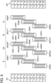
- Fig. 9 illustrates an example of back printing using two rows of white heads.
- the process color heads 300CM1 and 300YK1 discharge a color ink to form a color image.
- the white heads 300W3 and 300W6 discharge a white ink to complete a final image.
- the process color heads 300CM3 and 300YK3 discharge no color ink.
- the white heads 300W2 and 300W3 arranged on the left side are used, and the white heads 300W5 and 300W6 arranged on the right side are used. Therefore, a head having a nozzle length of Y1 is used as in the case of Fig. 7 .
- Fig. 10 illustrates an example of back printing using one row of white heads.
- the white head 300W1, the process color head 300CM1, the process color head 300YK1, and the white head 300W4 reach a print area
- the process color heads 300CM1 and 300YK1 discharge a color ink.
- the white heads 300W1 and 300W4 discharge no white ink.
- the white heads 300W3 and 300W6 discharge a white ink to complete a final image.
- the process color heads 300CM3 and 300YK3 discharge no color ink.
- the white head 300W3 disposed on the left side is used, and the white head 300W6 disposed on the right side is used. Therefore, a head having a nozzle length of Y2 is used as in the case of Fig. 8 .
- the liquid discharge apparatus 1 has several types of modes according to an application.
- a productivity-emphasizing mode that emphasizes productivity is referred to as, for example, a "draft mode” or a "production mode”
- an image quality-emphasizing mode that reduces productivity and emphasizes image quality is referred to as, for example, a "quality mode", a "high quality mode”, or a "fine mode”.
- Fig. 11 is a graph illustrating a relationship between a line feed amount and productivity.
- the line feed amount and productivity are calculated from the number of nozzles of a head being used, nozzle resolution, the number of scans, a head arrangement condition, and the like.
- high productivity has been demanded.
- it is only required to reduce the number of scans and to increase the line feed amount.
- FIG. 12 is an example illustrating the dot shape of an ink on a forward path or a backward path of the carriage 200.
- a surface of a dot is rough and the gloss is low
- the surface of the dot is smooth and the gloss is high.
- Gloss banding is likely to occur due to a difference in dot surface roughness and gloss between the forward path and the backward path of the carriage 200.
- an image is completed by a plurality of scan operations, but image data for each scan is generated using a print mask function.
- the amount of ink to be discharged was increased or decreased by using a tool for changing a parameter of the print mask function.
- a discharge amount was calculated by converting a weight difference of the base material 101 before and after printing and an image area into the weight of one head.
- Fig. 13 is a graph obtained by plotting a relationship between a discharge amount (mg/cm 2 ) per scan of one head and a line feed amount (cm).
- Fig. 14 is a graph obtained by plotting a relationship between a discharge amount (mg/cm 2 ) per scan of one head and productivity (m 2 /h).
- Gloss banding can be improved by lowering the ink discharge amount.
- the density (white concealing property) of the white base cannot be secured.
- Figs. 13 and 14 are graphs in which conditions under which the white concealing property can be secured are plotted.
- the white concealing property means that a white ink layer printed on a transparent base material conceals a base. A reflection density is measured while a black sheet is laid as an underlay under a white patch image printed on the transparent base material.
- Figs. 13 and 14 plot data of five different print modes (high quality mode, quality mode, standard mode, production mode, and imaginary mode).
- the range A illustrated in Figs. 13 and 14 is a range in which there is no disadvantage in gloss banding even with a one-row configuration of white heads. Under a condition in which the line feed amount is small and the productivity is low, there is no disadvantage in gloss banding and white concealing property as long as the discharge amount is within a range of 0.2 to 0.4 mg/cm 2 .
- the range B illustrated in Figs. 13 and 14 illustrates a condition in which gloss banding does not occur although the discharge amount is required to be 0.2 mg/cm 2 or more in order to secure the white concealing property in a one-row configuration of white heads. That is, it is indicated that the condition in which the line feed amount is 7 mm or more ( Fig. 13 ) and the productivity exceeds 20 m 2 /h ( Fig. 14 ) is disadvantageous for gloss banding Note that under this condition of the range B, gloss banding is reduced by lowering the ink discharge amount. However, in this case, the white concealing property is largely reduced disadvantageously.
- a condition of the range C illustrated in Figs. 13 and 14 is a range in which both the white concealing property and prevention of gloss banding are achieved while the liquid discharge apparatus 1 according to the embodiment has a two-row configuration of white heads.
- the liquid discharge apparatus 1 has a two-row configuration of white heads (nozzle length Y1) under a condition in which the line feed amount is large and the productivity is high. An operation of performing print by selecting the number of head rows according to a line feed amount will be described.
- a liquid discharge program is stored in the memory 32 illustrated in Fig. 3 .
- the CPU 33 executes the liquid discharge program to implement functions of a print mode determiner 71, a calculator 72, a head selector 73, and a print mask selector 74 illustrated in Fig. 15 .
- the print mode determiner 71 is an example of the determiner.
- the calculator 72, the head selector 73, and the print mask selector 74 are examples of the controller.
- All or some of the functions of the print mode determiner 71 to the print mask selector 74 may be implemented by hardware such as an integrated circuit (IC).
- IC integrated circuit
- the liquid discharge program may be recorded in a computer-readable recording medium such as a CD-ROM or a flexible disk (FD) with file information in an installable format or an executable format to be provided.
- the liquid discharge program may be recorded on a computer-readable recording medium such as a CD-R, a DVD, a Blu-ray (registered trademark) disk, or a semiconductor memory to be provided.
- the liquid discharge program may be provided in a form of being installed via a network such as the Internet.
- the liquid discharge program may be incorporated in a ROM or the like in an apparatus in advance to be provided.
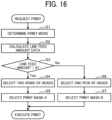
- Fig. 16 is a flowchart illustrating a flow of an operation of performing print by selecting the number of head rows (nozzle length) according to a line feed amount.
- the print mode determiner 71 determines a print mode (step S1).
- the memory 32 stores print condition data such as a line feed amount or productivity for each print mode.
- the calculator 72 refers to the print condition data to calculate line feed amount data (step S2).
- the head selector 73 determines whether or not the line feed amount data is equal to or larger than a predetermined amount "A" (step S3).
- "A" is "7 mm” in a case where the liquid discharge apparatus according to the embodiment is used.
- the head selector 73 selects a two-row configuration of white heads (nozzle length Y1) (step S4).
- the line feed amount data of 7 mm as an example can be changed to a desired value. For example, it is only required to change the value to a smaller value for a user who is strict in image quality, and it is only required to change the value to a larger value for a user who emphasizes a printing speed.
- a process color head 300CMC is used for process colors.
- the print mask selector 74 assigns a print mask A to the white heads 300W1 and 300W2 arranged on the left side and the white heads 300W4 and 300W5 arranged on the right side, that is, assigns the print mask A to a white head having a nozzle length of Y1 (step S5). Since the process color heads 300CM3 and 300YK3 are used as the process color heads, a color mask is assigned to these heads. Thereafter, printing is executed (print execution).
- the head selector 73 selects a one-row configuration of white heads (step S6).
- the head selector 73 selects the white heads 300W1 and 300W4 arranged at both ends in the head arrangement illustrated in Fig. 8 , and selects the process color head 300CMC for color.
- the print mask selector 74 assigns a print mask B to the white heads 300W1 and 300W4 arranged on the left side, that is, assigns the print mask B to a white head having a nozzle length of Y2 (step S7). Since the process color heads 300CM2, 300CM3, 300YK2, and 300YK3 are used for color, a color mask is assigned to these heads. Thereafter, printing is executed (print execution).
- an ink discharge amount per head is set to be about half the ink discharge amount in the one-row configuration. For this reason, the discharge amount of the print mask A assigned to the two-row configuration of white heads is half the discharge amount of the print mask B of the one-row configuration.
- Fig. 17 is a flowchart illustrating a flow of an operation of performing print by selecting the number of head rows according to productivity.
- the print mode determiner 71 determines a print mode (step S11).
- the memory 32 stores print condition data such as a line feed amount or productivity for each print mode.
- the calculator 72 refers to the print condition data to calculate productivity data (step S12).
- the head selector 73 determines whether or not the productivity data is equal to or larger than a predetermined amount "A" (step S13).
- A is "20 m 2 /h” in a case where the liquid discharge apparatus according to the embodiment is used.
- the set value of productivity may be changed according to an application of a user or the like.
- the head selector 73 selects a two-row configuration of white heads (step S14).
- a process color head 300CMC is used for process colors.
- the print mask selector 74 assigns the print mask A to the white heads 300W1 and 300W2 arranged on the left side and the white heads 300W4 and 300W5 arranged on the right side, that is, assigns the print mask A to a white heads having a nozzle length of Y1 (step S15). Since the process color heads 300CM3 and 300YK3 are used as the process color heads, a color mask is assigned to these heads. Thereafter, printing is executed (print execution).
- the head selector 73 selects a one-row configuration of white heads (step S16). In this case, the head selector 73 selects the white heads 300W1 and 300W4 arranged at both ends in the head arrangement illustrated in Fig. 8 , and selects the process color head 300CMC for color.
- the print mask selector 74 assigns the print mask B to the white heads 300W1 and 300W4 arranged on the left side, that is, assigns the print mask B to a white head having a nozzle length of Y2 (step S17). Since the process color heads 300CM2, 300CM3, 300YK2, and 300YK3 are used for color, a color mask is assigned to these heads. Thereafter, printing is executed (print execution).
- an ink discharge amount per head is set to be about half the ink discharge amount in the one-row configuration. For this reason, the discharge amount of the print mask A assigned to the two-row configuration of white heads is half the discharge amount of the print mask B of the one-row configuration.
- a head (nozzle length) to be used is the head described in Figs. 9 and 10 .
- an operation of performing print by selecting the number of head rows according to a line feed amount or productivity is similar to the case of front printing described above.
- the number of rows of white ink heads is selected according to productivity indicating the number of sheets that can be printed per unit time. That is, a two-row configuration is used under a condition of high productivity. In the case of the two-row configuration, the discharge amount of a white ink only needs to be about half the discharge amount in the one-row configuration. Therefore, even under a condition providing high productivity and being disadvantageous for prevention of gloss banding, by using a two-row configuration of white heads such that the discharge amount is half of the discharge amount in the one-row configuration, both a white concealing property and prevention of gloss banding can be achieved.
- the number of rows of white ink heads is selected according to a line feed amount. That is, a two-row configuration is used under a condition of a large line feed amount. In the case of the two-row configuration, the discharge amount of a white ink only needs to be about half the discharge amount in the one-row configuration. Therefore, even under a condition providing a large line feed amount and being disadvantageous for prevention of gloss banding, by using a two-row configuration of white heads such that the discharge amount is half of the discharge amount in the one-row configuration, both a white concealing property and prevention of gloss banding can be achieved.
- a three or more-row configuration of white heads may be used.
- a discharge amount required for securing a white concealing property by a plurality of heads is A mg/cm 2
- the number of rows of white heads used is n
- the number of heads used per row is m
- a discharge amount per head only needs to be "A/(n ⁇ m)" mg/cm 2 .
- a white ink discharge amount required for securing a white concealing property is A (mg/cm 2 )
- the number of rows of white ink heads selected is n (n represents two or more), and a discharge amount per white ink head is "A/n (mg/cm 2 )". For this reason, even in the three or more-row configuration of white heads, both a white concealing property and prevention of gloss banding can be achieved.
- the row configuration of white heads may be selected according to resolution.
- a mode in which the resolution in the sub-scanning direction is 300 dpi to 600 dpi has low to medium resolution, and can be therefore interpreted as a mode with high productivity.
- a mode of 900 dpi to 1800 dpi has high resolution, and can be therefore interpreted as a mode with low productivity.
- a case where the resolution in the sub-scanning direction is equal to or several times the nozzle pitch resolution has low to medium resolution with high productivity. Therefore, a row configuration (nozzle length) in which a plurality of rows of white heads is selected according to the resolution in the sub-scanning direction is used. As a result, it is possible to achieve both a white concealing property and prevention of gloss banding without reduction in productivity as in the first embodiment.
- a two-row configuration (nozzle length Y1) is used in a mode with high productivity.
- the discharge amount of a white ink only needs to be about half the discharge amount in the one-row configuration (nozzle length Y2). Therefore, even under a condition providing high productivity and being disadvantageous for prevention of gloss banding, by using a two-row configuration of white heads (nozzle length Y1) such that the discharge amount is half of the discharge amount in the one-row configuration (nozzle length Y2), both a white concealing property and prevention of gloss banding can be achieved.
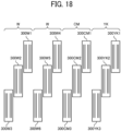
- Third Modification Front printing and back printing may be performed simultaneously.
- the CPU 33 controls color ink discharge from the process color heads 300CM1 and 300YK1. At this time, the CPU 33 does not cause the white heads 300W1 and 300W4 to discharge a white ink.
- the CPU 33 controls white ink discharge from the white heads 300W2 and 300W5. At this time, the CPU 33 does not cause the process color heads 300CM2 and 300YK2 to discharge a color ink.
- the CPU 33 controls line feed of the carriage 200 in the Y-axis direction again, and the white head 300W3, the process color head 300CM3, the process color head 300YK3, and the white head 300W6 reach a print area, the CPU 33 controls color ink discharge from the process color heads 300CM3 and 300YK3. At this time, the CPU 33 does not cause the white heads 300W3 and 300W6 to discharge a white ink.
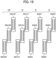
- a plurality of process color heads that discharges process color inks, respectively, and longitudinally three or more rows of white heads that discharge a white ink are arranged at two or more positions. Then, during a printing operation, an image is formed with each of the process colors, then an ink layer is formed with a white ink, and then an image is formed with the process colors.
- front printing and back printing can be simultaneously performed on a transparent base material, and an effect similar to the effects of the above-described first embodiment and Modifications can be obtained.
- the white heads 300W1 to 300W3 and 300W4 to 300W6 are arranged so as to sandwich the process color heads 300CM1 to 300CM3 and 300YK1 to 300YK3 arranged at the center from the left and right.
- a row of the white heads 300W1 to 300W3, a row of the white heads 300W4 to 300W6, a row of the process color heads 300CM1 to 300CM3, and a row of the process color heads 300YK1 to 300YK3 are sequentially arranged from the left to the right in the main scanning direction.
- the left two rows are the white heads 300W1 to 300W3 and the white heads 300W4 to 300W6, and adjacent to the rows of the white heads 300W1 to 300W6, a row of the process color heads 300CM1 to 300CM3 and a row of the process color heads 300YK1 to 300YK3 are sequentially arranged.
- Drive control of the white heads 300W1 to 300W6, the process color heads 300CM1 to 300CM3, and the process color heads 300YK1 to 300YK3 is similar to the drive control described above.
- a white ink discharge amount required for securing a white concealing property is A mg/cm 2
- the number of rows of white ink heads selected is n (n represents two or more, the number of heads used per row is m), and a discharge amount per white ink head is A/(n ⁇ m) mg/cm 2
- the number of white ink heads is selected according to the resolution in the sub-scanning direction, and a plurality of rows of white ink heads is selected in the case of a low resolution mode.
- the two rows of the white heads 300W1 to 300W3 and the white heads 300W4 to 300W6 are arranged on the right side, and adjacent to the rows of the white heads 300W1 to 300W6, a row of the process color heads 300CM1 to 300CM3 and a row of the process color heads 300YK1 to 300YK3 are sequentially arranged.
- a row of the white heads 300W4 to 300W6, a row of the white heads W1 to W3, a row of the process color heads 300YK1 to 300YK3, and a row of the process color heads 300CM1 to 300CM3 are sequentially arranged from the right to the left in an anti-main scanning direction.
- the right two rows are the white heads 300W1 to 300W3 and the white heads 300W4 to 300W6, and adjacent to the rows of the white heads 300W1 to 300W6, a row of the process color heads 300YK1 to 300YK3 and a row of the process color heads 300CM1 to 300CM3 are sequentially arranged in an anti-main scanning direction.
- Drive control of the white heads 300W1 to 300W6, the process color heads 300CM1 to 300CM3, and the process color heads 300YK1 to 300YK3 is similar to the drive control described above.
- a white ink discharge amount required for securing a white concealing property is A mg/cm 2
- the number of rows of white ink heads selected is n (n represents two or more, the number of heads used per row is m), and a discharge amount per white ink head is A/(n ⁇ m) mg/cm 2
- the number of white ink heads is selected according to the resolution in the sub-scanning direction, and a plurality of rows of white ink heads is selected in the case of a low resolution mode.
- the "liquid discharge apparatus 1" includes a liquid discharge head or a liquid discharge unit, and drives the liquid discharge head to discharge a liquid.
- the liquid discharge apparatus 1 include not only an apparatus capable of discharging a liquid onto an object to which the liquid can be attached but also an apparatus that discharges a liquid into a gas or a liquid.
- the “liquid discharge apparatus 1" may include a means related to feeding, transporting, and ejection of an object to which a liquid can be attached, and may also include a pre-processing device, a post-processing device, and the like.
- the "liquid discharge apparatus 1" may be an image forming apparatus that discharges an ink to form an image on a sheet, or a stereoscopic modeling apparatus (three-dimensional modeling apparatus) that discharges a modeling liquid onto a powder layer obtained by forming powder into a layer shape in order to model a stereoscopic modeled object (three-dimensional modeled object).
- a stereoscopic modeling apparatus three-dimensional modeling apparatus
- the "liquid discharge apparatus 1" is not limited to an apparatus in which a significant image such as a character or a graphic is visualized by a discharged liquid.
- Examples of the liquid discharge apparatus 1 also include an apparatus that forms a pattern or the like having no meaning in itself, and an apparatus that models a three-dimensional image.
- the "object to which a liquid can be attached” means an object to which a liquid can be attached at least temporarily, such as an object to which a liquid is attached and adheres, or an object to which a liquid is attached and permeates the object.
- Specific examples of the "object to which a liquid can be attached” include a recording medium such as a sheet, a recording sheet, a film, or cloth, an electronic component such as an electronic substrate or a piezoelectric element, and a medium such as a powder layer, an organ model, or a test cell. Unless otherwise specified, all objects to which a liquid is attached are included.
- a material of the "object to which a liquid can be attached” may be paper, thread, fiber, cloth, leather, metal, plastic, glass, wood, ceramics, or the like as long as a liquid can be attached to the object even temporarily.
- the "liquid” is not particularly limited as long as having such a viscosity and surface tension that the liquid can be discharged from a head.
- the liquid may preferably have a viscosity of 30 m [Pa s (Pascal second)] or less at normal temperature and normal pressure or after heating or cooling.
- the liquid include a solvent such as water or an organic solvent, and a solution, a suspension, and an emulsion containing a colorant such as a dye or a pigment, a function-imparting material such as a polymerizable compound, a resin, or a surfactant, a biocompatible material such as deoxyribonucleic acid (DNA), amino acid, protein, or calcium, or an edible material such as natural pigment.
- a solvent such as water or an organic solvent
- a colorant such as a dye or a pigment
- a function-imparting material such as a polymerizable compound, a resin
- the "liquid discharge apparatus 1" is not limited to an apparatus in which a liquid discharge head and an object to which a liquid can be attached are relatively moved. Specific examples of the liquid discharge apparatus 1 include a serial type apparatus that moves a liquid discharge head, and a line type apparatus that does not move a liquid discharge head.
- Examples of the "liquid discharge apparatus 1" further include a treatment liquid application apparatus that discharges a treatment liquid onto a sheet in order to apply the treatment liquid to a surface of the sheet, for example, in order to modify the surface of the sheet, and a spraying granulation apparatus that sprays a composition liquid in which a raw material is dispersed in a solution via a nozzle to granulate fine particles of the raw material.
- a treatment liquid application apparatus that discharges a treatment liquid onto a sheet in order to apply the treatment liquid to a surface of the sheet, for example, in order to modify the surface of the sheet
- a spraying granulation apparatus that sprays a composition liquid in which a raw material is dispersed in a solution via a nozzle to granulate fine particles of the raw material.
- the number of heads is changed based on productivity or the like, but the number of nozzles used in one head may be changed.
- the present invention can be implemented in any convenient form, for example using dedicated hardware, or a mixture of dedicated hardware and software.
- the present invention may be implemented as computer software implemented by one or more networked processing apparatuses.
- the processing apparatuses include any suitably programmed apparatuses such as a general purpose computer, personal digital assistant, mobile telephone (such as a WAP or 3G-compliant phone) and so on. Since the present invention can be implemented as software, each and every aspect of the present invention thus encompasses computer software implementable on a programmable device.
- the computer software can be provided to the programmable device using any conventional carrier medium (carrier means).
- the carrier medium includes a transient carrier medium such as an electrical, optical, microwave, acoustic or radio frequency signal carrying the computer code.
- An example of such a transient medium is a TCP/IP signal carrying computer code over an IP network, such as the Internet.
- the carrier medium may also include a storage medium for storing processor readable code such as a floppy disk, hard disk, CD ROM, magnetic tape device or solid state memory device.
- Processing circuitry includes a programmed processor, as a processor includes circuitry.
- a processing circuit also includes devices such as an application specific integrated circuit (ASIC), digital signal processor (DSP), field programmable gate array (FPGA), and conventional circuit components arranged to perform the recited functions.
- ASIC application specific integrated circuit
- DSP digital signal processor
- FPGA field programmable gate array
Landscapes
- Engineering & Computer Science (AREA)
- Quality & Reliability (AREA)
- Ink Jet (AREA)
- Particle Formation And Scattering Control In Inkjet Printers (AREA)
Claims (11)
- Flüssigkeitsausstoßvorrichtung (1), die dafür konfiguriert ist, eine UV-härtbare Tinte mit einer Vielzahl von Druckmodi auszustoßen, wobei die Flüssigkeitsausstoßvorrichtung (1) umfasst:einen Abtastwagen (200), der in einer Richtung senkrecht zur Zeilenzuführungsrichtung abtastet, umfassend eine Kopfeinheit (300), wobei die Kopfeinheit (300) eine Vielzahl von Volltonfarbenköpfen umfasst, wobei jeder Volltonfarbenkopf eine Vielzahl von Düsen umfasst,einen Bestimmer (71), der dafür konfiguriert ist, die Druckmodi zu bestimmen; undeinen Controller (3), der dafür konfiguriert ist, basierend auf dem von dem Bestimmer (71) bestimmten Druckmodus eine Nutzungsdüsenbreite und eine Ausstoßmenge eines Volltonfarbkopfes in einer Zeilenzuführungsrichtung zu ändern, so dass ein Druckmodus mit einer niedrigen Druckgeschwindigkeit in der Zeilenzuführungsrichtung eine schmalere Düsenbreite und eine größere Ausstoßmenge aufweist als ein Druckmodus mit einer hohen Druckgeschwindigkeit in der Zeilenzuführungsrichtung,wobei die Ausstoßmenge eines Volltonfarbenkopfes die Ausstoßmenge des Volltonfarbenkopfes pro Flächeneinheit bei einer Abtastung eines Kopfes ist, undwobei die Nutzungsdüsenbreite die Gesamtlänge der verwendeten Düse(n) in der Zeilenzuführungsrichtung ist.
- Flüssigkeitsausstoßvorrichtung (1) nach Anspruch 1,
wobei der Controller (3) die Nutzungsdüsenbreite und die Ausstoßmenge des Volltonfarbenkopfes in der Zeilenzuführungsrichtung entsprechend einer Produktivität ändert, die eine Anzahl von zu bedruckenden Blättern pro Zeiteinheit angibt. - Flüssigkeitsausstoßvorrichtung (1) nach Anspruch 2,
wobei der Controller (3) eine Änderung vornimmt, so dass die Nutzungsdüsenbreite des Volltonfarbkopfes in der Zeilenzuführungsrichtung vergrößert und die Ausstoßmenge verringert wird, wenn die Produktivität, die die Anzahl der pro Zeiteinheit bedruckbaren Blätter angibt, ein vorbestimmtes Niveau oder mehr beträgt, und die Nutzungsdüsenbreite des Volltonfarbkopfes in der Zeilenzuführungsrichtung verringert und die Ausstoßmenge erhöht wird, wenn die Produktivität, die die Anzahl der Blätter angibt, die pro Zeiteinheit gedruckt werden können, geringer als das vorbestimmte Niveau ist. - Flüssigkeitsausstoßvorrichtung (1) nach Anspruch 1,
wobei der Controller (3) die Nutzungsdüsenbreite und die Ausstoßmenge des Volltonfarbenkopfes in der Zeilenzuführungsrichtung entsprechend einer Zeilenzuführungsmenge in der Zeilenzuführungsrichtung ändert. - Flüssigkeitsausstoßvorrichtung (1) nach Anspruch 4,
wobei der Controller (3) eine Änderung vornimmt, so dass die Nutzungsdüsenbreite des Volltonfarbenkopfes in der Zeilenzuführungsrichtung vergrößert und die Ausstoßmenge verringert wird, wenn die Zeilenzuführungsmenge in der Zeilenzuführungsrichtung einen vorbestimmten Betrag oder mehr beträgt, und die Nutzdüsenbreite des Volltonfarbenkopfes in der Zeilenzuführungsrichtung verringert und die Ausstoßmenge erhöht wird, wenn die Zeilenzuführungsmenge in der Zeilenzuführungsrichtung kleiner als der vorbestimmte Betrag ist. - Flüssigkeitsausstoßvorrichtung (1) nach Anspruch 1,
wobei der Controller (3) die Nutzungsdüsenbreite und die Ausstoßmenge des Volltonfarbenkopfes in der Zeilenzuführungsrichtung entsprechend einer Auflösung des Volltonfarbenkopfes in der Zeilenzuführungsrichtung ändert. - Flüssigkeitsausstoßvorrichtung (1) nach Anspruch 6,
wobei der Controller (3) eine Änderung vornimmt, so dass die Nutzungsdüsenbreite des Volltonfarbenkopfes in der Zeilenzuführungsrichtung vergrößert und die Ausstoßmenge verringert wird, wenn die Auflösung in der Zeilenzuführungsrichtung niedrig ist, und die Nutzungsdüsenbreite des Volltonfarbkopfes in der Zeilenzuführungsrichtung verringert und die Ausstoßmenge erhöht wird, wenn die Auflösung in der Zeilenzuführungsrichtung hoch ist. - Flüssigkeitsausstoßvorrichtung (1) nach einem der Ansprüche 1 bis 7, die ferner eine Vielzahl von Volltonfarbenköpfen umfasst, die den Volltonfarbenkopf enthalten,
wobei der Controller (3) eine erforderliche Tintenausstoßmenge, die von der Vielzahl von Volltonfarbenköpfen ausgestoßen wird, als A festlegt, eine Anzahl von Reihen von Volltonfarbköpfen, die entsprechend der Nutzungsdüsenbreite des Volltonfarbkopfes in der Zeilenzuführungsrichtung ausgewählt werden, als n festlegt, wobei dies eine ganze Zahl von zwei oder mehr darstellt, die Anzahl der pro Reihe verwendeten Volltonfarbköpfe als m festlegt und die Ausstoßmenge pro Volltonfarbkopf als A / (n x m) festlegt. - Flüssigkeitsausstoßvorrichtung (1) nach einem der Ansprüche 1 bis 8,
wobei der Controller (3) einen Prozessfarbkopf und den Volltonfarbkopf so steuert, dass mit dem Prozessfarbkopf ein Bild auf einem Druckmedium erzeugt wird, dann mit dem Volltonfarbenkopf eine Aufzeichnungsschicht gebildet wird, und dann mit dem Prozessfarbenkopf wieder ein Bild gebildet wird. - Flüssigkeitsausstoßverfahren für eine Flüssigkeitsausstoßvorrichtung (1), die dafür konfiguriert ist, eine UV-härtbare Tinte mit einer Vielzahl von Druckmodi auszustoßen und einen Abtastwagen (200) aufweist, der in einer Richtung senkrecht zur Zeilenzuführungsrichtung abtastet, umfassend eine Kopfeinheit (300), wobei die Kopfeinheit (300) eine Vielzahl von Volltonfarbenköpfen umfasst, wobei jeder Volltonfarbenkopf eine Vielzahl von Düsen umfasst,
das Flüssigkeitsausstoßverfahren umfasst:Bestimmen der Druckmodi durch einen Bestimmer (71); undÄndern, basierend auf dem von dem Bestimmer (71) bestimmten Druckmodus, einer Nutzungsdüsenbreite und einer Ausstoßmenge eines Volltonfarbkopfes in einer Zeilenzuführungsrichtung, so dass ein Druckmodus mit einer niedrigen Druckgeschwindigkeit in der Zeilenzuführungsrichtung eine schmalere Düsenbreite und eine größere Ausstoßmenge aufweist als ein Druckmodus mit einer hohen Druckgeschwindigkeit in der Zeilenzuführungsrichtung durch einen Controller, wobei die Ausstoßmenge eines Volltonfarbenkopfes die Ausstoßmenge des Volltonfarbenkopfes pro Flächeneinheit bei einer Abtastung eines Kopfes ist, undwobei die Nutzungsdüsenbreite die Gesamtlänge der verwendeten Düse(n) in der Zeilenzuführungsrichtung ist. - Aufzeichnungsmedium, das ein Flüssigkeitsausstoßprogramm einer Flüssigkeitsausstoßvorrichtung (1) speichert, die dafür konfiguriert ist, eine UV-härtbare Tinte mit einer Vielzahl von Druckmodi auszustoßen und einen Abtastwagen (200) aufweist, der in einer Richtung senkrecht zur Zeilenzuführungsrichtung abtastet, umfassend eine Kopfeinheit (300), wobei die Kopfeinheit (300) eine Vielzahl von Volltonfarbenköpfen umfasst, wobei jeder Volltonfarbenkopf eine Vielzahl von Düsen umfasst,
wobei das Flüssigkeitsausstoßprogramm dafür konfiguriert ist, einen Computer zu veranlassen, als Folgendes zu arbeiten:als Bestimmer (71), der dafür konfiguriert ist, die Druckmodi zu bestimmen; undals Controller (3), der dafür konfiguriert ist, basierend auf dem von dem Bestimmer bestimmten Druckmodus eine Nutzungsdüsenbreite und eine Ausstoßmenge eines Volltonfarbkopfes in einer Zeilenzuführungsrichtung zu ändern, so dass ein Druckmodus mit einem niedrigen Druck in der Zeilenzuführungsrichtungsgeschwindigkeit eine schmalere Düsenbreite und eine größere Ausstoßmenge aufweist als ein Druckmodus mit einer hohen Druckgeschwindigkeit in der Zeilenzuführungsrichtung,wobei die Ausstoßmenge eines Volltonfarbenkopfes die Ausstoßmenge des Volltonfarbenkopfes pro Flächeneinheit bei einer Abtastung eines Kopfes ist, undwobei die Nutzungsdüsenbreite die Gesamtlänge der verwendeten Düse(n) in der Zeilenzuführungsrichtung ist.
Applications Claiming Priority (2)
| Application Number | Priority Date | Filing Date | Title |
|---|---|---|---|
| JP2019104023A JP7326886B2 (ja) | 2019-06-03 | 2019-06-03 | 液体吐出装置、液体吐出方法及び液体吐出プログラム |
| PCT/IB2020/054994 WO2020245702A1 (en) | 2019-06-03 | 2020-05-27 | Liquid discharge apparatus, liquid discharge method, and recording medium |
Publications (2)
| Publication Number | Publication Date |
|---|---|
| EP3976385A1 EP3976385A1 (de) | 2022-04-06 |
| EP3976385B1 true EP3976385B1 (de) | 2024-02-21 |
Family
ID=70977549
Family Applications (1)
| Application Number | Title | Priority Date | Filing Date |
|---|---|---|---|
| EP20730488.2A Active EP3976385B1 (de) | 2019-06-03 | 2020-05-27 | Flüssigkeitsausstossvorrichtung, flüssigkeitsausstossverfahren und aufzeichnungsmedium |
Country Status (5)
| Country | Link |
|---|---|
| US (1) | US11958298B2 (de) |
| EP (1) | EP3976385B1 (de) |
| JP (1) | JP7326886B2 (de) |
| CN (1) | CN114206622B (de) |
| WO (1) | WO2020245702A1 (de) |
Families Citing this family (4)
| Publication number | Priority date | Publication date | Assignee | Title |
|---|---|---|---|---|
| WO2022215490A1 (ja) * | 2021-04-05 | 2022-10-13 | 富士フイルム株式会社 | 階調補正データ生成装置、階調補正データ生成方法、プログラム及び画像形成システム |
| JP2023135240A (ja) * | 2022-03-15 | 2023-09-28 | ローランドディー.ジー.株式会社 | インクジェットプリンタ |
| US12365187B2 (en) | 2022-03-23 | 2025-07-22 | Ricoh Company, Ltd. | Liquid application apparatus, liquid application method, and storage medium |
| JPWO2024080281A1 (de) * | 2022-10-11 | 2024-04-18 |
Family Cites Families (23)
| Publication number | Priority date | Publication date | Assignee | Title |
|---|---|---|---|---|
| JP4931165B2 (ja) | 2000-08-31 | 2012-05-16 | キヤノン株式会社 | 画像記録装置および画像処理装置 |
| JP4065492B2 (ja) | 2001-05-15 | 2008-03-26 | キヤノン株式会社 | インクジェットプリント装置、インクジェットプリント方法、プログラムおよび該プログラムを格納したコンピュータにより読取可能な記憶媒体 |
| JP2003285427A (ja) | 2002-01-25 | 2003-10-07 | Konica Corp | インクジェットプリンタ |
| JP4250427B2 (ja) | 2002-02-06 | 2009-04-08 | キヤノン株式会社 | 印刷制御装置、印刷制御方法、及び印刷制御プログラム |
| JP4364156B2 (ja) | 2005-04-18 | 2009-11-11 | ブラザー工業株式会社 | 複合機 |
| US7401877B2 (en) | 2006-09-22 | 2008-07-22 | Xerox Corporation | Printing mode for a printer |
| JP4986599B2 (ja) | 2006-12-18 | 2012-07-25 | キヤノン株式会社 | インクジェット記録装置およびインクジェット記録方法 |
| JP5655357B2 (ja) | 2009-11-05 | 2015-01-21 | セイコーエプソン株式会社 | 印刷装置、及び、印刷方法 |
| JP5742154B2 (ja) | 2010-09-30 | 2015-07-01 | セイコーエプソン株式会社 | 印刷装置 |
| CN103946027B (zh) | 2012-02-22 | 2016-06-29 | 北京美科艺数码科技发展有限公司 | 一种喷墨打印装置及打印方法 |
| US9061492B2 (en) | 2013-03-07 | 2015-06-23 | Ricoh Company, Ltd. | Image recording apparatus, image recording method, and recording medium storing a program for recording image |
| PL2839970T3 (pl) | 2013-08-21 | 2018-04-30 | Hueck Rheinische Gmbh | Sposób wytwarzania hydrofobowej albo superhydrofobowej topografii powierzchniowej |
| WO2015042846A1 (zh) * | 2013-09-27 | 2015-04-02 | 北京美科艺数码科技发展有限公司 | 喷墨打印方法和喷墨打印装置 |
| JP6492742B2 (ja) | 2015-02-20 | 2019-04-03 | 株式会社リコー | 画像形成装置、画像形成方法およびプログラム |
| JP2016159531A (ja) * | 2015-03-02 | 2016-09-05 | 株式会社ミマキエンジニアリング | インクジェット記録装置及びインクジェット記録方法 |
| US9566799B1 (en) * | 2015-10-14 | 2017-02-14 | Funai Electric Co., Ltd. (Jp) | Imaging apparatus and method for reducing banding |
| JP6790343B2 (ja) * | 2015-10-16 | 2020-11-25 | セイコーエプソン株式会社 | ドット記録装置、ドット記録物の生産方法、コンピュータープログラム |
| JP7019960B2 (ja) | 2016-06-08 | 2022-02-16 | 株式会社リコー | 印刷装置、プログラム、及び印刷方法 |
| EP3372413B1 (de) * | 2017-03-10 | 2020-05-13 | Ricoh Company, Ltd. | Drucker und druckverfahren |
| JP7069853B2 (ja) | 2017-03-10 | 2022-05-18 | 株式会社リコー | 印刷装置及び印刷方法 |
| JP6514262B2 (ja) * | 2017-04-18 | 2019-05-15 | ローランドディー.ジー.株式会社 | インクジェットプリンタおよび印刷方法 |
| JP6871143B2 (ja) | 2017-12-12 | 2021-05-12 | 住友重機械工業株式会社 | プレス成形システム |
| JP7081219B2 (ja) | 2018-03-05 | 2022-06-07 | 株式会社リコー | 液体吐出装置、及びプログラム |
-
2019
- 2019-06-03 JP JP2019104023A patent/JP7326886B2/ja active Active
-
2020
- 2020-05-27 WO PCT/IB2020/054994 patent/WO2020245702A1/en not_active Ceased
- 2020-05-27 EP EP20730488.2A patent/EP3976385B1/de active Active
- 2020-05-27 US US17/440,803 patent/US11958298B2/en active Active
- 2020-05-27 CN CN202080035338.4A patent/CN114206622B/zh active Active
Also Published As
| Publication number | Publication date |
|---|---|
| US20220212479A1 (en) | 2022-07-07 |
| WO2020245702A1 (en) | 2020-12-10 |
| US11958298B2 (en) | 2024-04-16 |
| JP7326886B2 (ja) | 2023-08-16 |
| WO2020245702A8 (en) | 2021-10-07 |
| CN114206622A (zh) | 2022-03-18 |
| CN114206622B (zh) | 2023-06-23 |
| EP3976385A1 (de) | 2022-04-06 |
| JP2020196208A (ja) | 2020-12-10 |
Similar Documents
| Publication | Publication Date | Title |
|---|---|---|
| EP3976385B1 (de) | Flüssigkeitsausstossvorrichtung, flüssigkeitsausstossverfahren und aufzeichnungsmedium | |
| CN113165381B (zh) | 液体喷射装置、程序和喷射控制方法 | |
| JP5824891B2 (ja) | 印刷装置及び印刷方法 | |
| EP2522519A2 (de) | Tintenstrahlaufzeichnungsvorrichtung und Bilderzeugungsverfahren | |
| US10286688B2 (en) | Liquid discharge apparatus, liquid curing method, and computer program product | |
| JP5891612B2 (ja) | 印刷方法及び印刷装置 | |
| JP6040820B2 (ja) | グロスコントロールテーブル追加方法 | |
| US10994529B2 (en) | Liquid discharge apparatus, discharge adjustment method, and discharge adjustment program | |
| US11230119B2 (en) | Liquid discharge apparatus, liquid discharge method, and non-transitory recording medium | |
| JP4608992B2 (ja) | インクジェットプリンタ | |
| JP2004237588A (ja) | インクジェット記録装置 | |
| US11279141B2 (en) | Liquid discharging apparatus, method for discharging liquid and recording medium | |
| JP5845692B2 (ja) | 印刷装置及び印刷方法 | |
| JP7135683B2 (ja) | 液体吐出装置、方法、およびプログラム | |
| US11179950B2 (en) | Liquid discharge apparatus and liquid discharge method | |
| JP5845691B2 (ja) | 印刷装置及び印刷方法 | |
| EP4067096B1 (de) | Bilderzeugungsgerät, bilderzeugungsverfahren und trägermedium | |
| US11597213B2 (en) | Liquid jetting apparatus and jetting control method | |
| WO2020111199A1 (en) | Liquid ejection device, program and ejection control method | |
| JP2004299062A (ja) | インクジェットプリンタ | |
| JP2018130902A (ja) | 印刷装置 |
Legal Events
| Date | Code | Title | Description |
|---|---|---|---|
| STAA | Information on the status of an ep patent application or granted ep patent |
Free format text: STATUS: UNKNOWN |
|
| STAA | Information on the status of an ep patent application or granted ep patent |
Free format text: STATUS: THE INTERNATIONAL PUBLICATION HAS BEEN MADE |
|
| PUAI | Public reference made under article 153(3) epc to a published international application that has entered the european phase |
Free format text: ORIGINAL CODE: 0009012 |
|
| STAA | Information on the status of an ep patent application or granted ep patent |
Free format text: STATUS: REQUEST FOR EXAMINATION WAS MADE |
|
| 17P | Request for examination filed |
Effective date: 20210903 |
|
| AK | Designated contracting states |
Kind code of ref document: A1 Designated state(s): AL AT BE BG CH CY CZ DE DK EE ES FI FR GB GR HR HU IE IS IT LI LT LU LV MC MK MT NL NO PL PT RO RS SE SI SK SM TR |
|
| DAV | Request for validation of the european patent (deleted) | ||
| DAX | Request for extension of the european patent (deleted) | ||
| GRAP | Despatch of communication of intention to grant a patent |
Free format text: ORIGINAL CODE: EPIDOSNIGR1 |
|
| STAA | Information on the status of an ep patent application or granted ep patent |
Free format text: STATUS: GRANT OF PATENT IS INTENDED |
|
| INTG | Intention to grant announced |
Effective date: 20231016 |
|
| GRAS | Grant fee paid |
Free format text: ORIGINAL CODE: EPIDOSNIGR3 |
|
| P01 | Opt-out of the competence of the unified patent court (upc) registered |
Effective date: 20231213 |
|
| GRAA | (expected) grant |
Free format text: ORIGINAL CODE: 0009210 |
|
| STAA | Information on the status of an ep patent application or granted ep patent |
Free format text: STATUS: THE PATENT HAS BEEN GRANTED |
|
| AK | Designated contracting states |
Kind code of ref document: B1 Designated state(s): AL AT BE BG CH CY CZ DE DK EE ES FI FR GB GR HR HU IE IS IT LI LT LU LV MC MK MT NL NO PL PT RO RS SE SI SK SM TR |
|
| REG | Reference to a national code |
Ref country code: GB Ref legal event code: FG4D |
|
| REG | Reference to a national code |
Ref country code: CH Ref legal event code: EP |
|
| REG | Reference to a national code |
Ref country code: DE Ref legal event code: R096 Ref document number: 602020026049 Country of ref document: DE |
|
| REG | Reference to a national code |
Ref country code: IE Ref legal event code: FG4D |
|
| REG | Reference to a national code |
Ref country code: LT Ref legal event code: MG9D |
|
| REG | Reference to a national code |
Ref country code: NL Ref legal event code: MP Effective date: 20240221 |
|
| PG25 | Lapsed in a contracting state [announced via postgrant information from national office to epo] |
Ref country code: IS Free format text: LAPSE BECAUSE OF FAILURE TO SUBMIT A TRANSLATION OF THE DESCRIPTION OR TO PAY THE FEE WITHIN THE PRESCRIBED TIME-LIMIT Effective date: 20240621 |
|
| PG25 | Lapsed in a contracting state [announced via postgrant information from national office to epo] |
Ref country code: LT Free format text: LAPSE BECAUSE OF FAILURE TO SUBMIT A TRANSLATION OF THE DESCRIPTION OR TO PAY THE FEE WITHIN THE PRESCRIBED TIME-LIMIT Effective date: 20240221 |
|
| PG25 | Lapsed in a contracting state [announced via postgrant information from national office to epo] |
Ref country code: GR Free format text: LAPSE BECAUSE OF FAILURE TO SUBMIT A TRANSLATION OF THE DESCRIPTION OR TO PAY THE FEE WITHIN THE PRESCRIBED TIME-LIMIT Effective date: 20240522 |
|
| REG | Reference to a national code |
Ref country code: AT Ref legal event code: MK05 Ref document number: 1658812 Country of ref document: AT Kind code of ref document: T Effective date: 20240221 |
|
| PG25 | Lapsed in a contracting state [announced via postgrant information from national office to epo] |
Ref country code: RS Free format text: LAPSE BECAUSE OF FAILURE TO SUBMIT A TRANSLATION OF THE DESCRIPTION OR TO PAY THE FEE WITHIN THE PRESCRIBED TIME-LIMIT Effective date: 20240521 Ref country code: NL Free format text: LAPSE BECAUSE OF FAILURE TO SUBMIT A TRANSLATION OF THE DESCRIPTION OR TO PAY THE FEE WITHIN THE PRESCRIBED TIME-LIMIT Effective date: 20240221 Ref country code: HR Free format text: LAPSE BECAUSE OF FAILURE TO SUBMIT A TRANSLATION OF THE DESCRIPTION OR TO PAY THE FEE WITHIN THE PRESCRIBED TIME-LIMIT Effective date: 20240221 |
|
| PG25 | Lapsed in a contracting state [announced via postgrant information from national office to epo] |
Ref country code: ES Free format text: LAPSE BECAUSE OF FAILURE TO SUBMIT A TRANSLATION OF THE DESCRIPTION OR TO PAY THE FEE WITHIN THE PRESCRIBED TIME-LIMIT Effective date: 20240221 |
|
| PG25 | Lapsed in a contracting state [announced via postgrant information from national office to epo] |
Ref country code: AT Free format text: LAPSE BECAUSE OF FAILURE TO SUBMIT A TRANSLATION OF THE DESCRIPTION OR TO PAY THE FEE WITHIN THE PRESCRIBED TIME-LIMIT Effective date: 20240221 |
|
| PG25 | Lapsed in a contracting state [announced via postgrant information from national office to epo] |
Ref country code: RS Free format text: LAPSE BECAUSE OF FAILURE TO SUBMIT A TRANSLATION OF THE DESCRIPTION OR TO PAY THE FEE WITHIN THE PRESCRIBED TIME-LIMIT Effective date: 20240521 Ref country code: NO Free format text: LAPSE BECAUSE OF FAILURE TO SUBMIT A TRANSLATION OF THE DESCRIPTION OR TO PAY THE FEE WITHIN THE PRESCRIBED TIME-LIMIT Effective date: 20240521 Ref country code: NL Free format text: LAPSE BECAUSE OF FAILURE TO SUBMIT A TRANSLATION OF THE DESCRIPTION OR TO PAY THE FEE WITHIN THE PRESCRIBED TIME-LIMIT Effective date: 20240221 Ref country code: LT Free format text: LAPSE BECAUSE OF FAILURE TO SUBMIT A TRANSLATION OF THE DESCRIPTION OR TO PAY THE FEE WITHIN THE PRESCRIBED TIME-LIMIT Effective date: 20240221 Ref country code: IS Free format text: LAPSE BECAUSE OF FAILURE TO SUBMIT A TRANSLATION OF THE DESCRIPTION OR TO PAY THE FEE WITHIN THE PRESCRIBED TIME-LIMIT Effective date: 20240621 Ref country code: HR Free format text: LAPSE BECAUSE OF FAILURE TO SUBMIT A TRANSLATION OF THE DESCRIPTION OR TO PAY THE FEE WITHIN THE PRESCRIBED TIME-LIMIT Effective date: 20240221 Ref country code: GR Free format text: LAPSE BECAUSE OF FAILURE TO SUBMIT A TRANSLATION OF THE DESCRIPTION OR TO PAY THE FEE WITHIN THE PRESCRIBED TIME-LIMIT Effective date: 20240522 Ref country code: FI Free format text: LAPSE BECAUSE OF FAILURE TO SUBMIT A TRANSLATION OF THE DESCRIPTION OR TO PAY THE FEE WITHIN THE PRESCRIBED TIME-LIMIT Effective date: 20240221 Ref country code: ES Free format text: LAPSE BECAUSE OF FAILURE TO SUBMIT A TRANSLATION OF THE DESCRIPTION OR TO PAY THE FEE WITHIN THE PRESCRIBED TIME-LIMIT Effective date: 20240221 Ref country code: BG Free format text: LAPSE BECAUSE OF FAILURE TO SUBMIT A TRANSLATION OF THE DESCRIPTION OR TO PAY THE FEE WITHIN THE PRESCRIBED TIME-LIMIT Effective date: 20240221 Ref country code: AT Free format text: LAPSE BECAUSE OF FAILURE TO SUBMIT A TRANSLATION OF THE DESCRIPTION OR TO PAY THE FEE WITHIN THE PRESCRIBED TIME-LIMIT Effective date: 20240221 |
|
| PG25 | Lapsed in a contracting state [announced via postgrant information from national office to epo] |
Ref country code: PT Free format text: LAPSE BECAUSE OF FAILURE TO SUBMIT A TRANSLATION OF THE DESCRIPTION OR TO PAY THE FEE WITHIN THE PRESCRIBED TIME-LIMIT Effective date: 20240621 Ref country code: PL Free format text: LAPSE BECAUSE OF FAILURE TO SUBMIT A TRANSLATION OF THE DESCRIPTION OR TO PAY THE FEE WITHIN THE PRESCRIBED TIME-LIMIT Effective date: 20240221 |
|
| PG25 | Lapsed in a contracting state [announced via postgrant information from national office to epo] |
Ref country code: SE Free format text: LAPSE BECAUSE OF FAILURE TO SUBMIT A TRANSLATION OF THE DESCRIPTION OR TO PAY THE FEE WITHIN THE PRESCRIBED TIME-LIMIT Effective date: 20240221 Ref country code: PT Free format text: LAPSE BECAUSE OF FAILURE TO SUBMIT A TRANSLATION OF THE DESCRIPTION OR TO PAY THE FEE WITHIN THE PRESCRIBED TIME-LIMIT Effective date: 20240621 Ref country code: PL Free format text: LAPSE BECAUSE OF FAILURE TO SUBMIT A TRANSLATION OF THE DESCRIPTION OR TO PAY THE FEE WITHIN THE PRESCRIBED TIME-LIMIT Effective date: 20240221 Ref country code: LV Free format text: LAPSE BECAUSE OF FAILURE TO SUBMIT A TRANSLATION OF THE DESCRIPTION OR TO PAY THE FEE WITHIN THE PRESCRIBED TIME-LIMIT Effective date: 20240221 |
|
| PG25 | Lapsed in a contracting state [announced via postgrant information from national office to epo] |
Ref country code: DK Free format text: LAPSE BECAUSE OF FAILURE TO SUBMIT A TRANSLATION OF THE DESCRIPTION OR TO PAY THE FEE WITHIN THE PRESCRIBED TIME-LIMIT Effective date: 20240221 |
|
| PG25 | Lapsed in a contracting state [announced via postgrant information from national office to epo] |
Ref country code: SM Free format text: LAPSE BECAUSE OF FAILURE TO SUBMIT A TRANSLATION OF THE DESCRIPTION OR TO PAY THE FEE WITHIN THE PRESCRIBED TIME-LIMIT Effective date: 20240221 |
|
| PG25 | Lapsed in a contracting state [announced via postgrant information from national office to epo] |
Ref country code: CZ Free format text: LAPSE BECAUSE OF FAILURE TO SUBMIT A TRANSLATION OF THE DESCRIPTION OR TO PAY THE FEE WITHIN THE PRESCRIBED TIME-LIMIT Effective date: 20240221 Ref country code: EE Free format text: LAPSE BECAUSE OF FAILURE TO SUBMIT A TRANSLATION OF THE DESCRIPTION OR TO PAY THE FEE WITHIN THE PRESCRIBED TIME-LIMIT Effective date: 20240221 |
|
| PG25 | Lapsed in a contracting state [announced via postgrant information from national office to epo] |
Ref country code: SK Free format text: LAPSE BECAUSE OF FAILURE TO SUBMIT A TRANSLATION OF THE DESCRIPTION OR TO PAY THE FEE WITHIN THE PRESCRIBED TIME-LIMIT Effective date: 20240221 |
|
| PG25 | Lapsed in a contracting state [announced via postgrant information from national office to epo] |
Ref country code: SM Free format text: LAPSE BECAUSE OF FAILURE TO SUBMIT A TRANSLATION OF THE DESCRIPTION OR TO PAY THE FEE WITHIN THE PRESCRIBED TIME-LIMIT Effective date: 20240221 Ref country code: SK Free format text: LAPSE BECAUSE OF FAILURE TO SUBMIT A TRANSLATION OF THE DESCRIPTION OR TO PAY THE FEE WITHIN THE PRESCRIBED TIME-LIMIT Effective date: 20240221 Ref country code: RO Free format text: LAPSE BECAUSE OF FAILURE TO SUBMIT A TRANSLATION OF THE DESCRIPTION OR TO PAY THE FEE WITHIN THE PRESCRIBED TIME-LIMIT Effective date: 20240221 Ref country code: EE Free format text: LAPSE BECAUSE OF FAILURE TO SUBMIT A TRANSLATION OF THE DESCRIPTION OR TO PAY THE FEE WITHIN THE PRESCRIBED TIME-LIMIT Effective date: 20240221 Ref country code: DK Free format text: LAPSE BECAUSE OF FAILURE TO SUBMIT A TRANSLATION OF THE DESCRIPTION OR TO PAY THE FEE WITHIN THE PRESCRIBED TIME-LIMIT Effective date: 20240221 Ref country code: CZ Free format text: LAPSE BECAUSE OF FAILURE TO SUBMIT A TRANSLATION OF THE DESCRIPTION OR TO PAY THE FEE WITHIN THE PRESCRIBED TIME-LIMIT Effective date: 20240221 |
|
| REG | Reference to a national code |
Ref country code: DE Ref legal event code: R097 Ref document number: 602020026049 Country of ref document: DE |
|
| PG25 | Lapsed in a contracting state [announced via postgrant information from national office to epo] |
Ref country code: IT Free format text: LAPSE BECAUSE OF FAILURE TO SUBMIT A TRANSLATION OF THE DESCRIPTION OR TO PAY THE FEE WITHIN THE PRESCRIBED TIME-LIMIT Effective date: 20240221 |
|
| PLBE | No opposition filed within time limit |
Free format text: ORIGINAL CODE: 0009261 |
|
| STAA | Information on the status of an ep patent application or granted ep patent |
Free format text: STATUS: NO OPPOSITION FILED WITHIN TIME LIMIT |
|
| REG | Reference to a national code |
Ref country code: CH Ref legal event code: PL |
|
| PG25 | Lapsed in a contracting state [announced via postgrant information from national office to epo] |
Ref country code: IT Free format text: LAPSE BECAUSE OF FAILURE TO SUBMIT A TRANSLATION OF THE DESCRIPTION OR TO PAY THE FEE WITHIN THE PRESCRIBED TIME-LIMIT Effective date: 20240221 |
|
| PG25 | Lapsed in a contracting state [announced via postgrant information from national office to epo] |
Ref country code: MC Free format text: LAPSE BECAUSE OF FAILURE TO SUBMIT A TRANSLATION OF THE DESCRIPTION OR TO PAY THE FEE WITHIN THE PRESCRIBED TIME-LIMIT Effective date: 20240221 |
|
| PG25 | Lapsed in a contracting state [announced via postgrant information from national office to epo] |
Ref country code: LU Free format text: LAPSE BECAUSE OF NON-PAYMENT OF DUE FEES Effective date: 20240527 |
|
| 26N | No opposition filed |
Effective date: 20241122 |
|
| PG25 | Lapsed in a contracting state [announced via postgrant information from national office to epo] |
Ref country code: MC Free format text: LAPSE BECAUSE OF FAILURE TO SUBMIT A TRANSLATION OF THE DESCRIPTION OR TO PAY THE FEE WITHIN THE PRESCRIBED TIME-LIMIT Effective date: 20240221 Ref country code: LU Free format text: LAPSE BECAUSE OF NON-PAYMENT OF DUE FEES Effective date: 20240527 Ref country code: CH Free format text: LAPSE BECAUSE OF NON-PAYMENT OF DUE FEES Effective date: 20240531 |
|
| REG | Reference to a national code |
Ref country code: BE Ref legal event code: MM Effective date: 20240531 |
|
| PG25 | Lapsed in a contracting state [announced via postgrant information from national office to epo] |
Ref country code: IE Free format text: LAPSE BECAUSE OF NON-PAYMENT OF DUE FEES Effective date: 20240527 |
|
| PG25 | Lapsed in a contracting state [announced via postgrant information from national office to epo] |
Ref country code: SI Free format text: LAPSE BECAUSE OF FAILURE TO SUBMIT A TRANSLATION OF THE DESCRIPTION OR TO PAY THE FEE WITHIN THE PRESCRIBED TIME-LIMIT Effective date: 20240221 Ref country code: BE Free format text: LAPSE BECAUSE OF NON-PAYMENT OF DUE FEES Effective date: 20240531 |
|
| PGFP | Annual fee paid to national office [announced via postgrant information from national office to epo] |
Ref country code: DE Payment date: 20250521 Year of fee payment: 6 |
|
| PGFP | Annual fee paid to national office [announced via postgrant information from national office to epo] |
Ref country code: GB Payment date: 20250527 Year of fee payment: 6 |
|
| PGFP | Annual fee paid to national office [announced via postgrant information from national office to epo] |
Ref country code: FR Payment date: 20250528 Year of fee payment: 6 |
|
| PG25 | Lapsed in a contracting state [announced via postgrant information from national office to epo] |
Ref country code: HU Free format text: LAPSE BECAUSE OF FAILURE TO SUBMIT A TRANSLATION OF THE DESCRIPTION OR TO PAY THE FEE WITHIN THE PRESCRIBED TIME-LIMIT; INVALID AB INITIO Effective date: 20200527 |
|
| PG25 | Lapsed in a contracting state [announced via postgrant information from national office to epo] |
Ref country code: CY Free format text: LAPSE BECAUSE OF FAILURE TO SUBMIT A TRANSLATION OF THE DESCRIPTION OR TO PAY THE FEE WITHIN THE PRESCRIBED TIME-LIMIT; INVALID AB INITIO Effective date: 20200527 |