EP3971081B1 - System zum manövrieren eines schiffes und verfahren zur steuerung eines schiffes - Google Patents
System zum manövrieren eines schiffes und verfahren zur steuerung eines schiffes Download PDFInfo
- Publication number
- EP3971081B1 EP3971081B1 EP21196288.1A EP21196288A EP3971081B1 EP 3971081 B1 EP3971081 B1 EP 3971081B1 EP 21196288 A EP21196288 A EP 21196288A EP 3971081 B1 EP3971081 B1 EP 3971081B1
- Authority
- EP
- European Patent Office
- Prior art keywords
- steering
- marine vessel
- speed
- steering speed
- controller
- Prior art date
- Legal status (The legal status is an assumption and is not a legal conclusion. Google has not performed a legal analysis and makes no representation as to the accuracy of the status listed.)
- Active
Links
Images


Classifications
-
- B—PERFORMING OPERATIONS; TRANSPORTING
- B63—SHIPS OR OTHER WATERBORNE VESSELS; RELATED EQUIPMENT
- B63H—MARINE PROPULSION OR STEERING
- B63H25/00—Steering; Slowing-down otherwise than by use of propulsive elements; Dynamic anchoring, i.e. positioning vessels by means of main or auxiliary propulsive elements
- B63H25/02—Initiating means for steering, for slowing down, otherwise than by use of propulsive elements, or for dynamic anchoring
-
- B—PERFORMING OPERATIONS; TRANSPORTING
- B63—SHIPS OR OTHER WATERBORNE VESSELS; RELATED EQUIPMENT
- B63B—SHIPS OR OTHER WATERBORNE VESSELS; EQUIPMENT FOR SHIPPING
- B63B79/00—Monitoring properties or operating parameters of vessels in operation
- B63B79/40—Monitoring properties or operating parameters of vessels in operation for controlling the operation of vessels, e.g. monitoring their speed, routing or maintenance schedules
-
- B—PERFORMING OPERATIONS; TRANSPORTING
- B63—SHIPS OR OTHER WATERBORNE VESSELS; RELATED EQUIPMENT
- B63H—MARINE PROPULSION OR STEERING
- B63H20/00—Outboard propulsion units, e.g. outboard motors or Z-drives; Arrangements thereof on vessels
- B63H20/08—Means enabling movement of the position of the propulsion element, e.g. for trim, tilt or steering; Control of trim or tilt
- B63H20/12—Means enabling steering
-
- B—PERFORMING OPERATIONS; TRANSPORTING
- B63—SHIPS OR OTHER WATERBORNE VESSELS; RELATED EQUIPMENT
- B63H—MARINE PROPULSION OR STEERING
- B63H21/00—Use of propulsion power plant or units on vessels
- B63H21/12—Use of propulsion power plant or units on vessels the vessels being motor-driven
- B63H21/17—Use of propulsion power plant or units on vessels the vessels being motor-driven by electric motor
-
- B—PERFORMING OPERATIONS; TRANSPORTING
- B63—SHIPS OR OTHER WATERBORNE VESSELS; RELATED EQUIPMENT
- B63H—MARINE PROPULSION OR STEERING
- B63H21/00—Use of propulsion power plant or units on vessels
- B63H21/21—Control means for engine or transmission, specially adapted for use on marine vessels
- B63H21/213—Levers or the like for controlling the engine or the transmission, e.g. single hand control levers
-
- B—PERFORMING OPERATIONS; TRANSPORTING
- B63—SHIPS OR OTHER WATERBORNE VESSELS; RELATED EQUIPMENT
- B63H—MARINE PROPULSION OR STEERING
- B63H25/00—Steering; Slowing-down otherwise than by use of propulsive elements; Dynamic anchoring, i.e. positioning vessels by means of main or auxiliary propulsive elements
- B63H25/42—Steering or dynamic anchoring by propulsive elements; Steering or dynamic anchoring by propellers used therefor only; Steering or dynamic anchoring by rudders carrying propellers
-
- B—PERFORMING OPERATIONS; TRANSPORTING
- B63—SHIPS OR OTHER WATERBORNE VESSELS; RELATED EQUIPMENT
- B63H—MARINE PROPULSION OR STEERING
- B63H25/00—Steering; Slowing-down otherwise than by use of propulsive elements; Dynamic anchoring, i.e. positioning vessels by means of main or auxiliary propulsive elements
- B63H25/52—Parts for steering not otherwise provided for
-
- G—PHYSICS
- G05—CONTROLLING; REGULATING
- G05D—SYSTEMS FOR CONTROLLING OR REGULATING NON-ELECTRIC VARIABLES
- G05D1/00—Control of position, course, altitude or attitude of land, water, air or space vehicles, e.g. using automatic pilots
- G05D1/0011—Control of position, course, altitude or attitude of land, water, air or space vehicles, e.g. using automatic pilots associated with a remote control arrangement
- G05D1/0016—Control of position, course, altitude or attitude of land, water, air or space vehicles, e.g. using automatic pilots associated with a remote control arrangement characterised by the operator's input device
-
- G—PHYSICS
- G05—CONTROLLING; REGULATING
- G05D—SYSTEMS FOR CONTROLLING OR REGULATING NON-ELECTRIC VARIABLES
- G05D1/00—Control of position, course, altitude or attitude of land, water, air or space vehicles, e.g. using automatic pilots
- G05D1/20—Control system inputs
- G05D1/22—Command input arrangements
- G05D1/221—Remote-control arrangements
- G05D1/222—Remote-control arrangements operated by humans
- G05D1/223—Command input arrangements on the remote controller, e.g. joysticks or touch screens
-
- B—PERFORMING OPERATIONS; TRANSPORTING
- B63—SHIPS OR OTHER WATERBORNE VESSELS; RELATED EQUIPMENT
- B63H—MARINE PROPULSION OR STEERING
- B63H21/00—Use of propulsion power plant or units on vessels
- B63H21/21—Control means for engine or transmission, specially adapted for use on marine vessels
- B63H2021/216—Control means for engine or transmission, specially adapted for use on marine vessels using electric control means
-
- B—PERFORMING OPERATIONS; TRANSPORTING
- B63—SHIPS OR OTHER WATERBORNE VESSELS; RELATED EQUIPMENT
- B63H—MARINE PROPULSION OR STEERING
- B63H25/00—Steering; Slowing-down otherwise than by use of propulsive elements; Dynamic anchoring, i.e. positioning vessels by means of main or auxiliary propulsive elements
- B63H25/02—Initiating means for steering, for slowing down, otherwise than by use of propulsive elements, or for dynamic anchoring
- B63H2025/026—Initiating means for steering, for slowing down, otherwise than by use of propulsive elements, or for dynamic anchoring using multi-axis control levers, or the like, e.g. joysticks, wherein at least one degree of freedom is employed for steering, slowing down, or dynamic anchoring
-
- B—PERFORMING OPERATIONS; TRANSPORTING
- B63—SHIPS OR OTHER WATERBORNE VESSELS; RELATED EQUIPMENT
- B63H—MARINE PROPULSION OR STEERING
- B63H25/00—Steering; Slowing-down otherwise than by use of propulsive elements; Dynamic anchoring, i.e. positioning vessels by means of main or auxiliary propulsive elements
- B63H25/02—Initiating means for steering, for slowing down, otherwise than by use of propulsive elements, or for dynamic anchoring
- B63H2025/028—Initiating means for steering, for slowing down, otherwise than by use of propulsive elements, or for dynamic anchoring using remote control means, e.g. wireless control; Equipment or accessories therefor
Definitions
- the present invention relates to a marine vessel maneuvering system according to the preamble of independent claim 1 and a control method of a marine vessel, and more particularly, it relates to a marine vessel maneuvering system that controls a propulsive force and steering based on a user's operation and a control method of a marine vessel.
- a marine vessel maneuvering system can be taken from the prior art document WO 2020/007471 A1 , or document US2019/377347 .
- a marine vessel maneuvering system that controls a propulsive force and steering based on a user's operation is known in general. Such a marine vessel maneuvering system is disclosed in WO 2017/082248 A1 , for example.
- WO 2017/082248 A1 discloses a marine propulsion unit that propels a hull.
- the marine propulsion unit disclosed in WO 2017/082248 A1 includes a propeller driven by a motor, a steering shaft, a motor controller, and a steering mechanism.
- the marine propulsion unit disclosed in WO 2017/082248 A1 is attached to the hull.
- a remote control and a steering wheel are provided on the hull.
- rotational driving of the propeller is controlled by the motor controller based on a user's operation on the remote controller such that the magnitude of a propulsive force to propel the hull is adjusted.
- the steering shaft is rotated by the steering mechanism based on a user's operation on the steering wheel such that the direction of the propulsive force is adjusted.
- both the magnitude of a propulsive force and a steering angle are adjusted based on a user's operation on an operator when the operator is moved from a neutral position by the user's operation on the operator. Then, when the operator is returned to the neutral position, the steering angle is returned to a reference position (a position at which the direction of the propulsive force is parallel to the forward-rearward direction of the hull) with generation of the propulsive force by the motor stopped.
- a steering mechanism is driven without generation of a propulsive force and generation of a water flow, and thus the driving noise of the steering mechanism is noticeable unlike a case in which the steering mechanism is driven with generation of a water flow.
- the driving noise of the steering mechanism is noticeable even when the steering angle is returned to the reference position without completely stopping generation of the propulsive force by the motor and with generation of a relatively small propulsive force.
- the propeller is driven by an engine, relatively loud operating noise is continuously generated by idling even with generation of the propulsive force stopped, and thus the driving noise of the steering mechanism is unlikely to be noticeable.
- said object is solved by a marine vessel maneuvering system and a control method of a marine vessel having the features of independent claims 1 and 17. Preferred embodiments are laid down in the dependent claims.
- a marine vessel maneuvering system includes a propulsive force generator configured to generate a propulsive force to propel a marine vessel, a steering mechanism configured to steer the propulsive force generator, and a controller configured or programmed to control the propulsive force of the propulsive force generator and steering by the steering mechanism based on a user's operation on an operator configured to maneuver the marine vessel.
- the controller is configured or programmed to control a steering speed to a first steering speed when the operator is moved from a neutral position, and to control the steering speed to a second steering speed that is lower than the first steering speed when the operator is returned to the neutral position.
- the controller is configured or programmed to control the steering speed to the first steering speed when the operator is moved from the neutral position, and to control the steering speed to the second steering speed that is lower than the first steering speed when the operator is returned to the neutral position. Accordingly, when the operator is returned to the neutral position, the steering speed at which the steering angle is returned to the reference position becomes relatively low. Therefore, when the steering angle is returned to the reference position, the driving speed of the steering mechanism is decreased such that the driving noise of the steering mechanism becomes relatively small. Consequently, a decrease in quietness due to the noticeable driving noise of the steering mechanism is significantly reduced or prevented.
- This advantageous effect is particularly effective when a propulsive force generator driven by a motor is provided in which the driving noise of a steering mechanism is likely to be noticeable. Furthermore, the consumption of components of the steering mechanism is significantly reduced or prevented by a decrease in the driving speed of the steering mechanism at which the steering angle is returned to the reference position, and thus the life of the components of the steering mechanism is improved.
- the controller is preferably configured or programmed to control the steering speed to the second steering speed with generation of the propulsive force of the propulsive force generator stopped when the operator is returned to the neutral position. Accordingly, the steering speed at which the steering angle is returned to the reference position with generation of the propulsive force stopped becomes relatively low. Consequently, a propulsive force is not generated, and a water flow is not generated. Thus, the steering speed becomes relatively low in a state in which the driving noise of the steering mechanism is likely to be noticeable, and thus the noticeable driving noise of the steering mechanism due to driving of the steering mechanism is effectively significantly reduced or prevented.
- the controller is preferably configured or programmed to control the steering speed to the second steering speed by adjusting a steering angle command value or a speed command value output to the steering mechanism when the operator is returned to the neutral position. Accordingly, the steering angle command value as the target value of the steering angle is continuously adjusted such that the steering speed is indirectly adjusted, and the speed command value as the speed of steering is adjusted such that the steering speed is directly adjusted. Thus, the steering speed at which the steering angle is returned to the reference position is easily controlled to the second steering speed.
- the controller is preferably configured or programmed to determine whether or not an actual steering angle that changes following the steering angle command value has reached the steering angle command value when the operator is returned to the neutral position, and to control the steering speed to the second steering speed when determining that the actual steering angle has reached the steering angle command value. Accordingly, when the steering angle is returned to the reference position, the steering speed is controlled to the second steering speed after the actual steering angle reaches the steering angle command value, and thus the steering angle command value is appropriately controlled such that the steering speed becomes the second steering speed.
- the controller configured or programmed to control the steering speed to the second steering speed by adjusting the steering command value or the speed command value
- the controller is preferably configured or programmed to control the steering speed to the second steering speed by adjusting the steering angle command value at predetermined intervals. Accordingly, the steering angle command value as the target value of the steering angle is adjusted at the predetermined intervals, and thus the steering speed at which the steering angle is returned to the reference position is more easily controlled to the second steering speed.
- the controller is preferably configured or programmed to control the steering speed to the second steering speed when the operator including at least one of a joystick, a steering wheel, or a remote control configured to maneuver the marine vessel is returned to the neutral position. Accordingly, in the marine vessel maneuvering system in which the marine vessel is maneuvered based on a user's operation on at least one of the joystick, the steering wheel, or the remote control, the steering speed at which the steering angle is returned to the reference position is relatively reduced such that a decrease in quietness is significantly reduced or prevented.
- the controller is preferably configured or programmed to control the steering speed to the second steering speed based on the operator being returned to the neutral position after an operation is performed to perform at least one of turning, lateral movement, or rotation of the marine vessel. Accordingly, the steering speed at which the steering angle is returned to the reference position after the marine vessel is turned, laterally moved, or rotated becomes relatively low. Consequently, when the operator is returned to the neutral position after the marine vessel is turned, laterally moved, or rotated, a propulsive force is not generated, and a water flow is not generated. Thus, the steering speed becomes relatively low in a state in which the driving noise of the steering mechanism is likely to be noticeable, and thus the noticeable driving noise of the steering mechanism due to driving of the steering mechanism is effectively significantly reduced or prevented.
- the second steering speed is preferably set to one half or less of the first steering speed. Accordingly, the steering speed at which the steering angle is returned to the reference position is sufficiently decreased such that the noticeable driving noise of the steering mechanism is significantly reduced or prevented.
- the first steering speed is preferably set to a maximum settable steering speed
- the second steering speed is preferably set to one half or less of the first steering speed
- the controller is preferably configured or programmed to control the steering speed to a constant second steering speed when the operator is returned to the neutral position. Accordingly, as compared with a case in which the second steering speed is changed, a control process for the steering speed at which the steering angle is returned to the reference position is simplified.
- the controller is preferably configured or programmed to control the steering mechanism to change the steering speed from the second steering speed to the first steering speed when the operator is moved from the neutral position while the steering mechanism is steering the propulsive force generator at the second steering speed. Accordingly, even when a subsequent operation is performed on the operator while the steering angle is being returned to the reference position with the steering speed decreased from the first steering speed to the second steering speed, steering by the steering mechanism is immediately controlled with the steering speed returned from the second steering speed to the first steering speed based on the subsequent operation on the operator.
- the steering mechanism preferably includes a motor, a steering shaft configured to perform the steering, and a plurality of gears configured to transmit a rotational force of the motor to the steering shaft
- the controller is preferably configured or programmed to control the steering mechanism to change the steering between being performed at the first steering speed and being performed at the second steering speed by adjusting a current supplied to the motor. Accordingly, the current supplied to the motor is adjusted such that the steering speed is easily controlled to the first steering speed and the second steering speed via the plurality of gears and the steering shaft.
- the consumption of the motor, the gears, and the steering shaft is significantly reduced or prevented by a decrease in the driving speed of the steering mechanism at which the steering angle is returned to the reference position. Therefore, the life of the motor, the gears, and the steering shaft is improved.
- the motor of the steering mechanism preferably includes a DC motor with a brush. Accordingly, the consumption of the brush of the DC motor with a brush is significantly reduced or prevented by a decrease in the driving speed of the steering mechanism at which the steering angle is returned to the reference position, and thus the life of the motor is effectively improved.
- the controller is preferably configured or programmed to perform a feedback control on the steering by the steering mechanism by a PI control. Accordingly, the accuracy of a control of steering by the steering mechanism is improved, and thus the accuracy of a control to change the steering speed to the second steering speed is improved.
- the propulsive force generator and the steering mechanism preferably include a plurality of sets of propulsive force generators and steering mechanisms
- the controller is preferably configured or programmed to control steering speeds of the steering mechanisms to the second steering speed when the operator is returned to the neutral position. Accordingly, even when a plurality of sets of propulsive force generators and steering mechanism are provided, the steering speeds of all of a plurality of steering mechanisms are controlled to the second steering speed, and thus the steering speed at which the steering angle is returned to the reference position becomes relatively low without shifting the timing of returning the steering angle to the reference position among the plurality of steering mechanisms.
- a marine vessel maneuvering system is preferably used for the marine vessel. Accordingly, in the marine vessel, a decrease in quietness due to the noticeable driving noise of a steering mechanism is significantly reduced or prevented.
- a control method of a marine vessel includes controlling a steering speed to a first steering speed when an operator is moved from a neutral position, and controlling the steering speed to a second steering speed that is lower than the first steering speed when the operator is returned to the neutral position.
- the steering speed is controlled to the first steering speed when the operator is moved from the neutral position, and the steering speed is controlled to the second steering speed that is lower than the first steering speed when the operator is returned to the neutral position. Accordingly, the steering speed at which a steering angle is returned to a reference position becomes relatively low, similarly to the marine vessel maneuvering system according to preferred embodiments of the present invention described above. Consequently, a decrease in quietness due to the noticeable driving noise of a steering mechanism is significantly reduced or prevented, similarly to the marine vessel maneuvering system according to preferred embodiments of the present invention described above.
- This advantageous effect is particularly effective when a propulsive force generator driven by a motor is provided in which the driving noise of a steering mechanism is likely to be noticeable, similarly to the marine vessel maneuvering system according to preferred embodiments of the present invention described above. Furthermore, the life of components of the steering mechanism is improved, similarly to the marine vessel maneuvering system according to preferred embodiments of the present invention described above.
- the structure of a marine vessel maneuvering system 100 and the structure of a marine vessel 110 according to preferred embodiments are now described with reference to FIGS. 1 to 7 .
- the marine vessel maneuvering system 100 is a system to maneuver the marine vessel 110. That is, the marine vessel maneuvering system 100 is a system used for the marine vessel 110.
- the marine vessel maneuvering system 100 is provided in the marine vessel 110.
- the marine vessel 110 (marine vessel maneuvering system 100 (see FIG. 3 )) includes a hull 111 and marine propulsion units 112.
- the marine propulsion units 112 are attached to the rear of the hull 111. That is, the marine propulsion units 112 are outboard motors.
- the marine vessel 110 is used for sightseeing in a canal and a lake, for example.
- the marine vessel 110 is a relatively small marine vessel.
- Arrow FWD and arrow BWD in FIG. 1 represent the front side and the rear side of the marine vessel 110, respectively.
- the propulsive force generator 10 includes a propeller 11. As shown in FIG. 3 , the propulsive force generator 10 includes a motor 12. As the motor 12 is rotated, the propeller 11 (see FIG. 2 ) rotates such that the propulsive force generator 10 generates a propulsive force. That is, the propulsive force generator 10 is an electric propulsive force generator (electric propulsion device) driven by the motor 12.
- FIGS. 2A, 2B, and 2C show a state in which the steering mechanism 20 is located at a reference position P10 (a position at which the direction of the propulsive force is parallel to the forward-rearward direction of the marine vessel 110), a state in which the steering mechanism 20 is steered in the starboard direction from the reference position P10 such that the marine vessel 110 changes its course in the portside direction, and a state in which the steering mechanism 20 is steered in the portside direction from the reference position P10 such that the marine vessel 110 changes its course in the starboard direction, respectively.
- a reference position P10 a position at which the direction of the propulsive force is parallel to the forward-rearward direction of the marine vessel 110
- a state in which the steering mechanism 20 is steered in the starboard direction from the reference position P10 such that the marine vessel 110 changes its course in the portside direction
- a state in which the steering mechanism 20 is steered in the portside direction from the reference position P10 such that the marine vessel 110 changes its course
- the steering mechanism 20 includes a motor 21, a steering shaft 22 to perform steering (change the direction of the propulsive force), and a plurality of gears 23 to transmit the rotational force of the motor 21 to the steering shaft 22.
- the steering shaft 22 is a shaft fixed to the propulsive force generator 10.
- the motor 21 is a DC motor with a brush.
- the plurality of gears 23 include a spur gear 23a, a spur gear 23b, a spur gear 23c, a spur gear 23d, a worm gear 23e, and a worm wheel 23f.
- the steering mechanism 20 rotates the steering shaft 22 with rotation of the motor 21 to steer the propulsive force generator 10 (change the direction of the propulsive force generator 10).
- rotation of the motor 21 is decelerated by the plurality of gears 23 (at a reduction ratio of about 1/400, for example) and transmitted to the steering shaft 22.
- FIG. 1 shows a state in which the steering mechanism 20 is located at the reference position P10 (a position at which the direction of the propulsive force is parallel to the forward-rearward direction of the marine vessel 110), and a state in which the orientation of the steering mechanism 20 is changed by a steering angle ⁇ from the reference position P10 with chain lines and solid lines, respectively.
- a plurality of (two) marine propulsion units 112 are provided for one marine vessel 110. That is, in the marine vessel maneuvering system 100, a plurality of sets (two sets) of propulsive force generators 10 and steering mechanisms 20 are provided.
- the hull 111 (marine vessel maneuvering system 100) includes an operator 30 to maneuver the marine vessel 110.
- the operator 30 receives a user's (a user of the marine vessel 110) operation.
- the operator 30 includes a remote control 31, a steering wheel 32, and a joystick 33.
- the remote control 31 includes a lever to adjust the propulsive force, and the lever is operated such that the propulsive force generator 10 (the magnitude of the propulsive force of the propulsive force generator 10) is controlled.
- the steering wheel 32 is rotatable, and the steering mechanism 20 (steering by the steering mechanism 20) is controlled according to the amount of rotation of the steering wheel 32.
- the joystick 33 includes a base 33a and a lever 33b.
- the lever 33b is attached so as to be tiltable and rotatable with respect to the base 33a.
- the propulsive force generator 10 (the magnitude of the propulsive force of the propulsive force generator 10) and the steering mechanism 20 (steering by the steering mechanism 20) are controlled according to the amount and direction of tilting of the lever 33b.
- the propulsive force generator 10 (the magnitude of the propulsive force of the propulsive force generator 10) and the steering mechanism 20 (steering by the steering mechanism 20) are controlled according to the amount of rotation of the lever 33b.
- the lever 33b is urged by an urging member such as a spring so as to automatically return to a neutral position P20 (a position at which the lever 33b is upright) when not touched by the user.
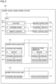
- the hull 111 (marine vessel maneuvering system 100) includes a first controller 41, a second controller 42, and a control switch 43.
- the first controller 41, the second controller 42, and the control switch 43 are circuit boards including a central processing unit (CPU), a read-only memory (ROM), a random access memory (RAM), etc., for example.
- the second controller 42 is an example of a "controller”.
- the first controller 41 controls the propulsive force of the propulsive force generator 10 and steering by the steering mechanism 20 based on user's operations on the steering wheel 32 and the remote control 31.
- the second controller 42 controls the propulsive force of the propulsive force generator 10 and steering by the steering mechanism 20 based on a user's operation on the joystick 33.
- the first controller 41 and the second controller 42 performs a feedback control on the propulsive force of the propulsive force generator 10 and steering by the steering mechanism 20 by a PI control.
- the propulsive force generator 10 includes a propulsive force controller 13 and a rotation speed sensor 14.
- the propulsive force controller 13 includes a motor driver and an inverter, for example.
- the rotation speed sensor 14 detects the rotation speed of the motor 12.
- the first controller 41 and the second controller 42 control the rotation speed of the motor 12 via the propulsive force controller 13 such that the rotation speed of the motor 12 detected by the rotation speed sensor 14 becomes a target value.
- the steering mechanism 20 includes a steering controller 24 and a steering angle sensor 25.
- the steering controller 24 includes a motor driver, for example.
- the steering angle sensor 25 detects the rotation angle of the steering shaft 22 (see FIG. 4 ).
- the steering mechanism 20 includes a sensor gear 26.
- the sensor gear 26 includes a spur gear 26a and a spur gear 26b.
- the spur gear 26a is fixed to the worm wheel 23f so as to rotate coaxially with the worm wheel 23f.
- the spur gear 26b meshes with the spur gear 26a and rotates about a steering angle sensor axis A2.
- the steering angle sensor 25 is provided adjacent to or in the vicinity of the spur gear 26b to detect the amount of rotation of the spur gear 26b.
- the steering angle sensor 25 is an optical sensor or a magnetic sensor, for example. As shown in FIG. 3 , the first controller 41 and the second controller 42 control the rotation speed of the motor 21 via the steering controller 24 such that the rotation angle of the steering shaft 22 detected by the steering angle sensor 25 becomes a target value.
- the control switch 43 switches between a state in which the first controller 41 controls the propulsive force of the propulsive force generator 10 and steering by the steering mechanism 20 and a state in which the second controller 42 controls the propulsive force of the propulsive force generator 10 and steering by the steering mechanism 20.
- a joystick mode switch 33c is provided on the base 33a of the joystick 33. The joystick mode switch 33c is pressed such that the control switch 43 switches between a state in which the marine vessel maneuvering system 100 receives an operation on the joystick 33 (joystick mode) and a state in which the marine vessel maneuvering system 100 does not receive an operation on the joystick 33.
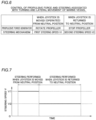
- the second controller 42 controls a steering speed V (see FIG. 7 ) to a first steering speed V1 when the joystick 33 is moved from the neutral position P20, and controls the steering speed V to a second steering speed V2 that is lower than the first steering speed V1 when the joystick 33 is returned to the neutral position P20.
- the second controller 42 controls the steering speed V to the second steering speed V2 with generation of the propulsive force of the propulsive force generator 10 stopped when the joystick 33 is returned to the neutral position P20.
- the second controller 42 controls the steering speed V to the second steering speed V2 based on the joystick 33 being returned to the neutral position P20 after an operation is performed to turn or laterally move the marine vessel 110.
- the second controller 42 controls both the propulsive force and the steering based on an operation on the joystick 33 when the joystick 33 is moved from the neutral position P20 by a user's operation on the joystick 33. That is, the second controller 42 controls the steering mechanism 20 to steer the propulsive force generator 10 at the first steering speed V1 with the propeller 11 of the propulsive force generator 10 rotated.
- the first steering speed V1 is set to a maximum steering speed V that is settable in the marine vessel maneuvering system 100.
- the second controller 42 controls the steering mechanism 20 to steer the propulsive force generator 10 at the second steering speed V2 such that the steering angle ⁇ (see FIG. 1 ) is returned to the reference position P10 (see FIG. 1 ) with generation of the propulsive force stopped. That is, the second controller 42 controls the steering mechanism 20 to steer the propulsive force generator 10 at the second steering speed V2 with rotation of the propeller 11 of the propulsive force generator 10 stopped.
- FIG. 3 controls the steering mechanism 20 to steer the propulsive force generator 10 at the second steering speed V2 such that the steering angle ⁇ (see FIG. 1 ) is returned to the reference position P10 (see FIG. 1 ) with generation of the propulsive force stopped.
- the second steering speed V2 is set to one half or less of the first steering speed V1 (which is the maximum steering speed V that is settable in the marine vessel maneuvering system 100).
- FIG. 7 shows a case in which the first steering speed V1 is half of the second steering speed V2.
- the second steering speed V2 is a constant steering speed V. That is, according to preferred embodiments, the second controller 42 controls the steering speed V to the constant second steering speed V2 when the operator 30 is returned to the neutral position P20.
- the second controller 42 controls the steering mechanism 20 to change steering between being performed at the first steering speed V1 (see FIG. 6 ) and being performed at the second steering speed V2 (see FIG. 6 ) by adjusting a current supplied to the motor 21.
- the second controller 42 controls the steering controller 24 to adjust power supplied to the motor 21 of the steering mechanism 20 so as to adjust the amount of rotation of the motor 21.
- the amount of rotation of the motor 21 is adjusted such that the rotation angle (steering speed V) of the steering shaft 22 of the steering mechanism 20 per unit time is adjusted.
- the second controller 42 controls the steering speed V to the second steering speed V2 (see FIG. 6 ) by adjusting a steering angle command value ⁇ (see FIG. 8 ) output to the steering mechanism 20 when the joystick 33 is returned to the neutral position P20 (see FIG. 5 ).
- the second controller 42 controls the steering speed V to the second steering speed V2 by adjusting the steering angle command value ⁇ at predetermined intervals. More specifically, the second controller 42 adjusts and outputs the steering angle command value ⁇ as the target value of the steering angle ⁇ (see FIG. 1 ) every time a predetermined time period (the control cycle of a PI control, for example) elapses to adjust the steering angle every predetermined time period. That is, the steering speed V is indirectly adjusted.
- the second controller 42 controls the steering speed V to the second steering speed V2 by filtering the steering angle command value ⁇ such that the steering angle becomes smaller than when the steering speed V is controlled to the first steering speed V1 before the predetermined time period elapses and outputting the filtered steering angle command value ⁇ to the steering mechanism 20.
- the second controller 42 determines whether or not an actual steering angle ⁇ that changes following the steering angle command value ⁇ has reached the steering angle command value ⁇ when the joystick 33 is returned to the neutral position P20, and controls the steering speed V to the second steering speed V2 when determining that the actual steering angle ⁇ has reached the steering angle command value ⁇ .
- the actual steering angle ⁇ may be larger than the steering angle command value ⁇ (the actual steering angle ⁇ may not reach the steering angle command value ⁇ ) immediately after the joystick 33 is returned to the neutral position P20.
- the second controller 42 controls the steering mechanism 20 such that the steering speed V becomes the second steering speed V2 (transmits the filtered steering angle command value to the steering mechanism 20) at the timing at which the actual steering angle ⁇ becomes smaller than the steering angle command value ⁇ (the steering angle command value ⁇ reaches the actual steering angle ⁇ ).
- the steering speed V is controlled to the first steering speed V1 until the actual steering angle ⁇ reaches the steering angle command value ⁇ .
- the second controller 42 controls the steering mechanism 20 to change the steering speed V from the second steering speed V2 to the first steering speed V1 when the joystick 33 is moved from the neutral position P20 while the steering mechanism 20 is steering the propulsive force generator 10 at the second steering speed V2.
- the second controller 42 controls the steering mechanism 20 such that the steering to return the steering angle ⁇ to the reference position P10 is interrupted, and steering based on the subsequent operation is immediately performed (at the first steering speed V1).
- the second controller 42 controls the steering speeds V of the plurality of sets (two sets) of steering mechanisms 20 to the second steering speed V2 when the operator 30 (joystick 33) is returned to the neutral position P20.
- a control flow of steering by the joystick 33 in the marine vessel maneuvering system 100 is now described with reference to FIG. 8 .
- a control shown in FIG. 8 is performed by the second controller 42.
- step S1 the second controller 42 determines whether or not the marine vessel maneuvering system 100 is in the joystick mode (a state in which an operation on the joystick 33 is received).
- step S2 the second controller 42 advances to step S2.
- step S3 the second controller 42 advances to step S3.
- step S2 the second controller 42 receives the steering angle command value ⁇ (the unfiltered steering angle command value ⁇ or the filtered steering angle command value ⁇ ) from the joystick 33. Then, the second controller 42 advances to step S4.
- step S3 the second controller 42 receives the steering angle command value ⁇ (the unfiltered steering angle command value ⁇ or the filtered steering angle command value ⁇ ) from the joystick 33 as in step S2. Then, the second controller 42 advances to step S5.
- step S4 the second controller 42 determines whether or not the marine propulsion unit 112 is attached to the hull 111. When determining in step S4 that the marine propulsion unit 112 is attached to the hull 111, the second controller 42 advances to step S6. When determining in step S4 that the marine propulsion unit 112 is not attached to the hull 111, the second controller 42 advances to step S5.
- step S6 the second controller 42 determines whether or not the joystick 33 is at the neutral position P20.
- the second controller 42 advances to step S7. That is, when the joystick 33 is returned to the neutral position P20, the second controller 42 advances to step S7 (and thus step 9 and step 10).
- step S5 the second controller 42 advances to step S5.
- step S7 the second controller 42 determines whether or not the steering angle command value ⁇ is smaller than the actual steering angle ⁇ (whether or not the actual steering angle ⁇ that changes following the steering angle command value ⁇ has reached the steering angle command value ⁇ ).
- step S7 When determining in step S7 that the steering angle command value ⁇ is smaller than the actual steering angle ⁇ (the actual steering angle ⁇ has reached the steering angle command value ⁇ ), the second controller 42 advances to step S8.
- step S7 When determining in step S7 that the steering angle command value ⁇ is not smaller than the actual steering angle ⁇ (the actual steering angle ⁇ has not reached the steering angle command value ⁇ ), the second controller 42 advances to step S5.
- step S8 the second controller 42 determines whether or not the previously transmitted value (previously transmitted steering angle command value ⁇ ) is filtered (whether or not the steering speed V is controlled to the second steering speed V2).
- the second controller 42 advances to step S9.
- the second controller 42 advances to step S10.
- step S9 the second controller 42 transmits the filtered steering angle command value ⁇ to the marine propulsion unit 112 (steering mechanism 20). Then, the second controller 42 returns to step S1. That is, step S9 is a step to control the steering speed V to the second steering speed V2 that is lower than the first steering speed V1.
- step S10 the second controller 42 filters the steering angle command value ⁇ and transmits it to the marine propulsion unit 112 (steering mechanism 20) (transmits a filtered initial steering angle command value). That is, step S10 is a step to control the steering speed V to the second steering speed V2 that is lower than the first steering speed V1. Then, the second controller 42 returns to step S1.
- step S1 when determining in step S1 that the marine vessel maneuvering system 100 is not in the joystick mode, the second controller 42 may return to step S1 without advancing to step S3.
- step S4 when determining in step S4 that the marine propulsion unit 112 is not attached to the hull 111, the second controller 42 may return to step S1 without advancing to step S5.
- the second controller 42 is configured or programmed to control the steering speed V to the first steering speed V1 when the joystick 33 is moved from the neutral position P20, and control the steering speed V to the second steering speed V2 that is lower than the first steering speed V1 when the operator 30 is returned to the neutral position P20. Accordingly, when the joystick 33 is returned to the neutral position P20, the steering speed V at which the steering angle ⁇ is returned to the reference position P10 becomes relatively low. Therefore, when the steering angle ⁇ is returned to the reference position P10, the driving speed of the steering mechanism 20 is decreased such that the driving noise of the steering mechanism 20 becomes relatively small. Consequently, a decrease in quietness due to the noticeable driving noise of the steering mechanism 20 is significantly reduced or prevented.
- the propulsive force generator 10 is an electric propulsive force generator driven by the motor 12.
- the driving noise of the steering mechanism 20 is particularly likely to be noticeable, and thus a decrease in quietness due to the noticeable driving noise of the steering mechanism 20 is effectively significantly reduced or prevented.
- the consumption of components of the steering mechanism 20 is significantly reduced or prevented by a decrease in the driving speed of the steering mechanism 20 at which the steering angle ⁇ is returned to the reference position P10, and thus the life of the components of the steering mechanism 20 is improved.
- the second controller 42 is configured or programmed to control the steering speed V to the second steering speed V2 with generation of the propulsive force of the propulsive force generator 10 stopped when the joystick 33 is returned to the neutral position P20. Accordingly, the steering speed V at which the steering angle ⁇ is returned to the reference position P10 with generation of the propulsive force stopped becomes relatively low. Consequently, a propulsive force is not generated, and a water flow is not generated. Thus, the steering speed V becomes relatively low in a state in which the driving noise of the steering mechanism 20 is likely to be noticeable, and thus the noticeable driving noise of the steering mechanism 20 due to driving of the steering mechanism 20 is effectively significantly reduced or prevented.
- the second controller 42 is configured or programmed to control the steering speed V to the second steering speed V2 by adjusting the steering angle command value ⁇ output to the steering mechanism 20 when the joystick 33 is returned to the neutral position P20. Accordingly, the steering angle command value ⁇ as the target value of the steering angle ⁇ is continuously adjusted such that the steering speed V is indirectly adjusted, and thus the steering speed V at which the steering angle ⁇ is returned to the reference position P10 is easily controlled to the second steering speed V2.
- the second controller 42 is configured or programmed to determine whether or not the actual steering angle ⁇ that changes following the steering angle command value ⁇ has reached the steering angle command value ⁇ when the joystick 33 is returned to the neutral position P20, and control the steering speed V to the second steering speed V2 when determining that the actual steering angle ⁇ has reached the steering angle command value ⁇ . Accordingly, when the steering angle ⁇ is returned to the reference position P10, the steering speed V is controlled to the second steering speed V2 after the actual steering angle ⁇ reaches the steering angle command value ⁇ , and thus the steering angle command value ⁇ is appropriately controlled such that the steering speed V becomes the second steering speed V2.
- the second controller 42 is configured or programmed to control the steering speed V to the second steering speed V2 by adjusting the steering angle command value ⁇ at the predetermined intervals. Accordingly, the steering angle command value ⁇ as the target value of the steering angle ⁇ is adjusted at the predetermined intervals, and thus the steering speed V at which the steering angle ⁇ is returned to the reference position P10 is more easily controlled to the second steering speed V2.
- the second controller 42 is configured or programmed to control the steering speed V to the second steering speed V2 based on the joystick 33 being returned to the neutral position P20 after an operation is performed to turn or laterally move the marine vessel 110. Accordingly, the steering speed V at which the steering angle ⁇ is returned to the reference position P10 after the marine vessel 110 is turned or laterally moved becomes relatively low. Consequently, when the joystick 33 is returned to the neutral position P20 after the marine vessel 110 is turned or laterally moved, a propulsive force is not generated, and a water flow is not generated. Thus, the steering speed V becomes relatively low in a state in which the driving noise of the steering mechanism 20 is likely to be noticeable, and thus the noticeable driving noise of the steering mechanism 20 due to driving of the steering mechanism 20 is effectively significantly reduced or prevented.
- the second steering speed V2 is set to one half or less of the first steering speed V1. Accordingly, the steering speed V at which the steering angle ⁇ is returned to the reference position P10 is sufficiently decreased such that the noticeable driving noise of the steering mechanism 20 is significantly reduced or prevented.
- the first steering speed V1 is set to the maximum settable steering speed V
- the second steering speed V2 is set to one half or less of the first steering speed V1. Accordingly, the joystick 33 is operated such that the steering speed V at which the steering angle ⁇ is returned to the reference position P10 is sufficiently decreased such that the noticeable driving noise of the steering mechanism 20 is significantly reduced or prevented without decreasing the steering speed V occurring when the operator 30 is moved from the neutral position P20.
- the second controller 42 is configured or programmed to control the steering speed V to the constant second steering speed V2 when the joystick 33 is returned to the neutral position P20. Accordingly, as compared with a case in which the second steering speed V2 is changed, a control process for the steering speed V at which the steering angle ⁇ is returned to the reference position P10 is simplified.
- the second controller 42 is configured or programmed to control the steering mechanism 20 to change the steering speed V from the second steering speed V2 to the first steering speed V1 when the joystick 33 is moved from the neutral position P20 while the steering mechanism 20 is steering the propulsive force generator 10 at the second steering speed V2. Accordingly, even when a subsequent operation is performed on the joystick 33 while the steering angle ⁇ is being returned to the reference position P10 with the steering speed V decreased from the first steering speed V1 to the second steering speed V2, steering by the steering mechanism 20 is immediately controlled with the steering speed V returned from the second steering speed V2 to the first steering speed V1 based on the subsequent operation on the joystick 33.
- the steering mechanism 20 includes the motor 21, the steering shaft 22 to perform steering, and the plurality of gears 23 to transmit the rotational force of the motor 21 to the steering shaft 22.
- the second controller 42 is configured or programmed to control the steering mechanism 20 to change steering between being performed at the first steering speed V1 and being performed at the second steering speed V2 by adjusting a current supplied to the motor 21. Accordingly, the current supplied to the motor 21 is adjusted such that the steering speed V is easily controlled to the first steering speed V1 and the second steering speed V2 via the plurality of gears 23 and the steering shaft 22.
- the consumption of the motor 21, the gears 23, and the steering shaft 22 is significantly reduced or prevented by a decrease in the driving speed of the steering mechanism 20 at which the steering angle ⁇ is returned to the reference position P10. Therefore, the life of the motor 21, the gears 23, and the steering shaft 22 is improved.
- the motor 21 of the steering mechanism 20 is a DC motor with a brush. Accordingly, the consumption of the brush of the DC motor with a brush is significantly reduced or prevented by a decrease in the driving speed of the steering mechanism 20 at which the steering angle ⁇ is returned to the reference position P10, and thus the life of the motor 21 is effectively improved.
- the second controller 42 is configured or programmed to perform a feedback control on steering by the steering mechanism 20 by a PI control. Accordingly, the accuracy of a control of steering by the steering mechanism 20 is improved, and thus the accuracy of a control to change the steering speed V to the second steering speed V2 is improved.
- the plurality of sets (two sets) of propulsive force generators 10 and steering mechanisms 20 are provided. Furthermore, the second controller 42 is configured or programmed to control the steering speeds V of the plurality of (two) steering mechanisms 20 to the second steering speed V2 when the joystick 33 is returned to the neutral position P20. Accordingly, even when a plurality of sets (two sets) of propulsive force generators 10 and steering mechanism 20 are provided, the steering speeds V of all of the plurality of steering mechanisms 20 are controlled to the second steering speed V2, and thus the steering speed V at which the steering angle ⁇ is returned to the reference position P10 becomes relatively low without shifting the timing of returning the steering angle ⁇ to the reference position P10 among the plurality of steering mechanisms 20.
- the marine vessel maneuvering system 100 is used for the marine vessel 110. Accordingly, in the marine vessel 110, a decrease in quietness due to the noticeable driving noise of the steering mechanism 20 is significantly reduced or prevented.
- the present teaching is not restricted to this.
- three or more sets of propulsive force generators and steering mechanisms may alternatively be provided, or only one set of a propulsive force generator and a steering mechanism may alternatively be provided.
- the second controller 42 (controller) preferably performs a feedback control on steering by the steering mechanism 20 by a PI control in the preferred embodiments described above, the present teaching is not restricted to this. In the present teaching, the controller may alternatively perform a feedback control on steering by the steering mechanism by a PD control or a PID control.
- the motor 21 of the steering mechanism 20 is preferably a DC motor with a brush in the preferred embodiments described above, the present teaching is not restricted to this.
- the motor of the steering mechanism may alternatively be a DC motor without a brush, or may be a motor other than a DC motor, such as an AC motor or a stepping motor.
- the second controller 42 (controller) preferably controls the steering mechanism 20 by adjusting a current supplied to the motor 21 in the preferred embodiments described above
- the present teaching is not restricted to this.
- the controller may alternatively control the steering mechanism by adjusting an oil pressure.
- the second controller 42 controls the steering mechanism 20 to change the steering speed V from the second steering speed V2 to the first steering speed V1 when the joystick 33 (operator) is moved from the neutral position P20 while the steering mechanism 20 is steering the propulsive force generator 10 at the second steering speed V2 in the preferred embodiments described above
- the controller may alternatively control the steering mechanism to not change the steering speed from the second steering speed to the first steering speed when the operator is moved from the neutral position while the steering mechanism is steering the propulsive force generator 10 at the second steering speed.
- the present teaching is not restricted to this.
- the controller may alternatively control the steering speed to a changing second steering speed when the operator is returned to the neutral position.
- first steering speed V1 is preferably set to the maximum settable steering speed V in the preferred embodiments described above, the present teaching is not restricted to this. In the present teaching, the first steering speed may alternatively be set to a value that is smaller than the maximum settable steering speed.
- the second steering speed V2 is preferably set to one half or less of the first steering speed V1 in the preferred embodiments described above, the present teaching is not restricted to this. In the present teaching, the second steering speed may alternatively be set to a value that is larger than one half of the first steering speed.
- the present teaching is not restricted to this.
- the controller may not control the steering speed to the second steering speed based on the operator being returned to the neutral position after an operation is performed to turn the marine vessel.
- the controller may not control the steering speed to the second steering speed based on the operator being returned to the neutral position after an operation is performed to laterally move the marine vessel.
- the controller may control the steering speed to the second steering speed based on the operator being returned to the neutral position after a maneuvering operation (such as rotation) other than turning and lateral movement of the marine vessel is performed.
- the second controller 42 (controller) preferably controls the steering speed V to the second steering speed V2 when the operator 30 is returned to the neutral position P20 based on a user's operation on the joystick 33 to steer the marine vessel 110 in the preferred embodiments described above
- the controller may alternatively control the steering speed to the second steering speed when the operator is returned to the neutral position based on a user's operation on the steering wheel or the remote control to steer the marine vessel.
- the present teaching is not restricted to this.
- the controller may alternatively control the steering speed to the second steering speed by adjusting a speed command value output to the steering mechanism when the operator is returned to the neutral position. In such a case, the steering speed is directly adjusted by adjusting the speed command value, and thus the steering speed at which the steering angle is returned to the reference position is easily controlled to the second steering speed.
- the second controller 42 (controller) preferably controls the steering speed V to the second steering speed V2 with generation of the propulsive force of the propulsive force generator 10 stopped when the joystick 33 (operator) is returned to the neutral position P20 in the preferred embodiments described above
- the controller may alternatively control the steering speed to the second steering speed without (completely) stopping generation of the propulsive force of the propulsive force generator when the operator is returned to the neutral position.
- propulsive force generator 10 is preferably an electric propulsive force generator driven by the motor 12 in the preferred embodiments described above, the present teaching is not restricted to this.
- the propulsive force generator may alternatively be a hybrid propulsive force generator driven by the motor and the engine.
Landscapes
- Engineering & Computer Science (AREA)
- Chemical & Material Sciences (AREA)
- Combustion & Propulsion (AREA)
- Mechanical Engineering (AREA)
- Ocean & Marine Engineering (AREA)
- Physics & Mathematics (AREA)
- General Physics & Mathematics (AREA)
- Aviation & Aerospace Engineering (AREA)
- Radar, Positioning & Navigation (AREA)
- Remote Sensing (AREA)
- Automation & Control Theory (AREA)
- Mathematical Physics (AREA)
- Theoretical Computer Science (AREA)
- Computing Systems (AREA)
- Control Of Position, Course, Altitude, Or Attitude Of Moving Bodies (AREA)
- Mechanical Control Devices (AREA)
- Steering Control In Accordance With Driving Conditions (AREA)
Claims (17)
- Ein Wasserfahrzeug-Manövriersystem (100) für ein Wasserfahrzeug (110), das umfasst:einen Vortriebskraftgenerator (10), der konfiguriert ist, um eine Vortriebskraft zu erzeugen, um das Wasserfahrzeug (110) anzutreiben;einen Lenkmechanismus (20), der konfiguriert ist, um den Vortriebskraftgenerator (10) zu lenken; undeine Steuerung (42), die konfiguriert oder programmiert ist, um die Vortriebskraft des Vortriebskraftgenerators (10) und Lenken durch den Lenkmechanismus (20) auf der Grundlage der Bedienung eines Benutzers durch einen Betätiger (30) zu steuern, der konfiguriert ist, um das Wasserfahrzeug (110) zu manövrieren, wobeidie Steuerung (42) konfiguriert oder programmiert ist, um eine Lenkgeschwindigkeit (V) zu steuern, wenn eine Änderung einer Ausrichtung des Vortriebskraftgenerators (10) in Bezug auf das Wasserfahrzeug (110) durch den Lenkmechanismus (20) von einer Referenzposition (P10), in der die Richtung der Vortriebskraft parallel zu einer Vorwärts-Rückwärts-Richtung des Wasserfahrzeugs (110) ist, auf eine erste Lenkgeschwindigkeit (V1), wenn der Betätiger (30) aus einer Neutralposition (P20) bewegt wird, gesteuert wird, dadurch gekennzeichnet, dass die Steuerung (42) konfiguriert oder programmiert ist, um die Lenkgeschwindigkeit (V) auf eine zweite Lenkgeschwindigkeit (V2) zu steuern, die niedriger ist als die erste Lenkgeschwindigkeit (V1), wenn der Betätiger (30) in die Neutralposition (P20) zurückgekehrt ist, um einen Lenkwinkel (θ) in die Referenzposition (P10) zurückzuführen.
- Das Wasserfahrzeug-Manövriersystem gemäß Anspruch 1, dadurch gekennzeichnet, dass die Steuerung (42) konfiguriert oder programmiert ist, um die Lenkgeschwindigkeit (V) auf die zweite Lenkgeschwindigkeit (V2) zu steuern, wobei die Erzeugung der Vortriebskraft des Vortriebskraftgenerators (10) gestoppt wird, wenn der Betätiger (30) in die Neutralposition (P20) zurückgekehrt ist.
- Das Wasserfahrzeug-Manövriersystem gemäß Anspruch 1 oder 2, dadurch gekennzeichnet, dass die Steuerung (42) konfiguriert oder programmiert ist, um die Lenkgeschwindigkeit (V) auf die zweite Lenkgeschwindigkeit (V2) zu steuern, durch einstellen eines Lenkwinkel-Befehlswerts (α) oder eines Geschwindigkeits-Befehlswerts, der an den Lenkmechanismus (20) ausgegeben wird, wenn der Betätiger (30) in die Neutralposition (P20) zurückgekehrt ist.
- Das Wasserfahrzeug-Manövriersystem gemäß Anspruch 3, dadurch gekennzeichnet, dass die Steuerung (42) konfiguriert oder programmiert ist, um festzustellen, ob ein momentaner Lenkwinkel (β), der sich nach dem Lenkwinkel-Befehlswert (α) ändert, den Lenkwinkel-Befehlswert (α) erreicht hat oder nicht, wenn der Betätiger (30) in die Neutralposition (P20) zurückgekehrt ist, und die Lenkgeschwindigkeit (V) auf die zweite Lenkgeschwindigkeit (V2) zu steuern, wenn feststellt ist, dass der momentane Lenkwinkel (β) den Lenkwinkel-Befehlswert (α) erreicht hat.
- Das Wasserfahrzeug-Manövriersystem gemäß Anspruch 3 oder 4, dadurch gekennzeichnet, dass die Steuerung (42) konfiguriert oder programmiert ist, um die Lenkgeschwindigkeit (V) auf die zweite Lenkgeschwindigkeit (V2) durch Anpassen des Steuerwinkel-Sollwerts (α) in vorgegebenen Intervallen zu steuern.
- Das Wasserfahrzeug-Manövriersystem gemäß irgendeinem der Ansprüche 1 bis 5, dadurch gekennzeichnet, dass die Steuerung (42) konfiguriert oder programmiert ist, um die Lenkgeschwindigkeit (V) auf die zweite Lenkgeschwindigkeit (V2) zu steuern, wenn der Betätiger (30), der zumindest einen Joystick (33), ein Lenkrad (32) oder eine Fernsteuerung (31) enthält, die zum Manövrieren des Wasserfahrzeugs (110) konfiguriert sind, in die Neutralposition (P20) zurückgekehrt ist.
- Das Wasserfahrzeug-Manövriersystem gemäß irgendeinem der Ansprüche 1 bis 6, dadurch gekennzeichnet, dass die Steuerung (42) konfiguriert oder programmiert ist, um die Lenkgeschwindigkeit (V) auf die zweite Lenkgeschwindigkeit (V2) zu steuern, auf Grundlage des Betätigers (30), der in die Neutralposition (P20) zurückgekehrt ist, nachdem ein Vorgang ausgeführt wurde, um zumindest eine Drehung, eine seitliche Bewegung oder eine Rotation des Wasserfahrzeugs (110) auszuführen.
- Das Wasserfahrzeug-Manövriersystem gemäß irgendeinem der Ansprüche 1 bis 7, dadurch gekennzeichnet, dass die zweite Lenkgeschwindigkeit (V2) auf die Hälfte oder weniger der ersten Lenkgeschwindigkeit (V1) eingestellt ist.
- Das Wasserfahrzeug-Manövriersystem gemäß Anspruch 8, dadurch gekennzeichnet, dass die erste Lenkgeschwindigkeit (V1) auf eine maximal einstellbare Lenkgeschwindigkeit eingestellt ist; und
die zweite Lenkgeschwindigkeit (V2) auf die Hälfte oder weniger der ersten Lenkgeschwindigkeit (V1) eingestellt ist. - Das Wasserfahrzeug-Manövriersystem gemäß irgendeinem der Ansprüche 1 bis 9, dadurch gekennzeichnet, dass die Steuerung (42) konfiguriert oder programmiert ist, um die Lenkgeschwindigkeit (V) auf eine konstante zweite Lenkgeschwindigkeit (V2) zu steuern, wenn der Betätiger (30) in die Neutralposition (P20) zurückgekehrt ist.
- Das Wasserfahrzeug-Manövriersystem gemäß irgendeinem der Ansprüche 1 bis 10, dadurch gekennzeichnet, dass die Steuerung (42) konfiguriert oder programmiert ist, um den Lenkmechanismus (20) zu steuern, um die Lenkgeschwindigkeit (V) von der zweiten Lenkgeschwindigkeit (V2) auf die erste Lenkgeschwindigkeit (V1) zu ändern, wenn der Betätiger (30) aus der Neutralposition (P20) bewegt ist, während der Lenkmechanismus (20) den Vortriebskraftgenerator (10) mit der zweiten Lenkgeschwindigkeit (V2) lenkt.
- Das Wasserfahrzeug-Manövriersystem gemäß irgendeinem der Ansprüche 1 bis 11,dadurch gekennzeichnet, dass der Lenkmechanismus (20) enthält:einen Motor (21);eine Lenkwelle (22), die konfiguriert ist, um die Lenkung auszuführen; undeine Mehrzahl von Zahnrädem (23), die konfiguriert sind, um eine Drehkraft des Motors (21) auf die Lenkwelle (22) zu übertragen; unddie Steuerung (42) konfiguriert oder programmiert ist, um den Lenkmechanismus (20) zu steuern, um Lenkung zwischen der Ausführung mit der ersten Lenkgeschwindigkeit (V1) und der Ausführung mit der zweiten Lenkgeschwindigkeit (V2) durch Einstellen eines Stroms, der dem Motor (21) zugeführt ist, zu wechseln.
- Das Wasserfahrzeug-Manövriersystem gemäß Anspruch 12, dadurch gekennzeichnet, dass der Motor (21) des Lenkmechanismus (20) einen Gleichstrommotor mit einer Bürste enthält.
- Das Wasserfahrzeug-Manövriersystem gemäß irgendeinem der Ansprüche 1 bis 13, dadurch gekennzeichnet, dass die Steuerung (42) konfiguriert oder programmiert ist, um eine Rückkopplungssteuerung der Lenkung durch den Lenkmechanismus (20) durch eine PI-Steuerung durchzuführen.
- Das Wasserfahrzeug-Manövriersystem gemäß irgendeinem der Ansprüche 1 bis 14, dadurch gekennzeichnet, dass der Vortriebskraftgenerator (10) und der Lenkmechanismus (20) eine Mehrzahl von Sätzen von Vortriebskraftgeneratoren (10) und Lenkmechanismen (20) enthalten; und
die Steuerung (42) konfiguriert oder programmiert ist, um die Lenkgeschwindigkeiten (V) der Lenkmechanismen (20) auf die zweite Lenkgeschwindigkeit (V2) zu steuern, wenn der Betätiger (30) in die Neutralposition (P20) zurückgekehrt ist. - Ein Wasserfahrzeug (110), das mit einem Wasserfahrzeug-Manövriersystem (100) gemäß irgendeinem der Ansprüche 1 bis 15 vorgesehen ist.
- Ein Steuerungsverfahren zum Steuern einer Vortriebskraft und einer Vortriebsausrichtung eines Wasserfahrzeugs (110), das einen Vortriebskraftgenerator (10), der konfiguriert ist, um eine Vortriebskraft zu erzeugen, um das Wasserfahrzeug (110) anzutreiben, und einem Lenkmechanismus (20), der konfiguriert ist, um den Vortriebskraftgenerator (10) zu lenken, hat, das Verfahren umfasst:
Steuern einer Lenkgeschwindigkeit (V), wenn eine Änderung einer Ausrichtung der Vortriebskraft in Bezug auf das Wasserfahrzeug (110) von einer Referenzposition (P10), bei der die Richtung der Vortriebskraft parallel zu einer Vorwärts-Rückwärts-Richtung des Wasserfahrzeugs (110) ist, gesteuert wird, auf eine erste Lenkgeschwindigkeit (V1), wenn ein Betätiger (30) aus einer Neutralposition (P20) bewegt ist, und das Verfahren gekenzechnet ist durch Steuern der Lenkgeschwindigkeit (V) auf eine zweite Lenkgeschwindigkeit (V2), die niedriger ist als die erste Lenkgeschwindigkeit (V1), wenn der Betätiger (30) in die Neutralposition (P20) zurückgekehrt ist, um einen Lenkwinkel (θ) in die Referenzposition (P10) zurückzuführen.
Applications Claiming Priority (1)
| Application Number | Priority Date | Filing Date | Title |
|---|---|---|---|
| JP2020154645A JP7132296B2 (ja) | 2020-09-15 | 2020-09-15 | 操船システムおよび船舶 |
Publications (2)
| Publication Number | Publication Date |
|---|---|
| EP3971081A1 EP3971081A1 (de) | 2022-03-23 |
| EP3971081B1 true EP3971081B1 (de) | 2025-05-21 |
Family
ID=77726408
Family Applications (1)
| Application Number | Title | Priority Date | Filing Date |
|---|---|---|---|
| EP21196288.1A Active EP3971081B1 (de) | 2020-09-15 | 2021-09-13 | System zum manövrieren eines schiffes und verfahren zur steuerung eines schiffes |
Country Status (3)
| Country | Link |
|---|---|
| US (1) | US11987338B2 (de) |
| EP (1) | EP3971081B1 (de) |
| JP (1) | JP7132296B2 (de) |
Families Citing this family (1)
| Publication number | Priority date | Publication date | Assignee | Title |
|---|---|---|---|---|
| JP2024165066A (ja) * | 2023-05-16 | 2024-11-28 | ヤマハ発動機株式会社 | 船舶推進システムおよび船舶 |
Family Cites Families (15)
| Publication number | Priority date | Publication date | Assignee | Title |
|---|---|---|---|---|
| JP3883108B2 (ja) * | 2001-12-10 | 2007-02-21 | 本田技研工業株式会社 | 車両操舵装置 |
| US6994046B2 (en) * | 2003-10-22 | 2006-02-07 | Yamaha Hatsudoki Kabushiki Kaisha | Marine vessel running controlling apparatus, marine vessel maneuvering supporting system and marine vessel each including the marine vessel running controlling apparatus, and marine vessel running controlling method |
| US7052341B2 (en) * | 2003-10-22 | 2006-05-30 | Yamaha Hatsudoki Kabushiki Kaisha | Method and apparatus for controlling a propulsive force of a marine vessel |
| JP4401798B2 (ja) | 2004-01-30 | 2010-01-20 | 株式会社川崎造船 | 蒸気タービン船の主タービントルク制限装置 |
| US7305928B2 (en) * | 2005-10-12 | 2007-12-11 | Brunswick Corporation | Method for positioning a marine vessel |
| US7267068B2 (en) * | 2005-10-12 | 2007-09-11 | Brunswick Corporation | Method for maneuvering a marine vessel in response to a manually operable control device |
| US20070277721A1 (en) * | 2006-06-01 | 2007-12-06 | John Charles Crotts | Watercraft steering and control apparatus with joystick |
| JP4791340B2 (ja) | 2006-12-22 | 2011-10-12 | ヤマハ発動機株式会社 | 船舶用推進装置の制御装置、ならびにそれを用いた航走支援システムおよび船舶 |
| JP2013163439A (ja) * | 2012-02-10 | 2013-08-22 | Yamaha Motor Co Ltd | 船外機の制御システム |
| JP2015116847A (ja) | 2013-12-16 | 2015-06-25 | ヤマハ発動機株式会社 | 船舶推進システムおよびそれを備えた船舶 |
| EP3705393B1 (de) | 2015-11-11 | 2022-04-27 | Yamaha Hatsudoki Kabushiki Kaisha | Schiffsantriebseinheit |
| US10766589B1 (en) * | 2017-12-19 | 2020-09-08 | Yamaha Hatsudoki Kabushiki Kaisha | System for and method of controlling watercraft |
| JP7135380B2 (ja) * | 2018-03-29 | 2022-09-13 | マツダ株式会社 | 車両用制御装置 |
| JP7141253B2 (ja) * | 2018-06-08 | 2022-09-22 | ヤマハ発動機株式会社 | 船舶推進装置の転舵装置 |
| US11584501B2 (en) | 2018-07-05 | 2023-02-21 | Volvo Penta Corporation | Joystick device for a marine vessel |
-
2020
- 2020-09-15 JP JP2020154645A patent/JP7132296B2/ja active Active
-
2021
- 2021-09-07 US US17/467,692 patent/US11987338B2/en active Active
- 2021-09-13 EP EP21196288.1A patent/EP3971081B1/de active Active
Also Published As
| Publication number | Publication date |
|---|---|
| US20220081096A1 (en) | 2022-03-17 |
| JP2022048683A (ja) | 2022-03-28 |
| EP3971081A1 (de) | 2022-03-23 |
| JP7132296B2 (ja) | 2022-09-06 |
| US11987338B2 (en) | 2024-05-21 |
Similar Documents
| Publication | Publication Date | Title |
|---|---|---|
| EP3722201B1 (de) | Schiffsantriebssystem und schiff | |
| US12286208B2 (en) | Marine vessel maneuvering system and marine vessel | |
| EP4357237B9 (de) | Wasserfahrzeugantriebssystem, wasserfahrzeug und wasserfahrzeugantriebssteuerungsverfahren | |
| JP4994005B2 (ja) | 船舶用操舵装置及び船舶 | |
| EP4089004A2 (de) | System zum manövrieren von schiffen | |
| EP3971081B1 (de) | System zum manövrieren eines schiffes und verfahren zur steuerung eines schiffes | |
| JP5289485B2 (ja) | 多機掛け船舶推進機の制御装置 | |
| JP2008126773A (ja) | 船舶用操舵装置及び船舶 | |
| JP2008126772A (ja) | 船舶用操舵装置及び船舶 | |
| EP4488162B1 (de) | Lenksteuerungsvorrichtung zur steuerung eines lenkmodus eines wasserfahrzeugs, verfahren dafür und wasserfahrzeug | |
| EP4516658A1 (de) | Schiffsantriebssystem, steuerungsverfahren dafür und wasserfahrzeug | |
| US20240228006A9 (en) | Marine propulsion system and marine vessel | |
| JP2023102964A (ja) | 船外機および船舶 | |
| JP2023068839A (ja) | 船舶推進システムおよび船舶 | |
| JP2023094870A (ja) | 船舶推進システムおよび船舶 | |
| EP4520648A1 (de) | Schiffsantriebssystem, steuerungsverfahren dafür und wasserfahrzeug | |
| EP4488161B1 (de) | Lenksteuerungsvorrichtung und steuerungsverfahren zur steuerung des drehwinkels einer antriebsvorrichtung bei der steuerung des lenkmodus sowie wasserfahrzeug | |
| EP4516659A1 (de) | Schiffsantriebssystem, steuerungsverfahren dafür und wasserfahrzeug | |
| JP2005280579A (ja) | 小型船舶用ステアリング装置 | |
| JP3260265B2 (ja) | 船舶の緊急時操船方法 | |
| EP4520647A1 (de) | Schiffsantriebssystem, steuerungsverfahren dafür und wasserfahrzeug | |
| US20250346336A1 (en) | System for and method of controlling watercraft | |
| US12479560B1 (en) | Marine propulsion system and control method | |
| JP2024101416A (ja) | 操船システムおよびそれを備える船舶 |
Legal Events
| Date | Code | Title | Description |
|---|---|---|---|
| PUAI | Public reference made under article 153(3) epc to a published international application that has entered the european phase |
Free format text: ORIGINAL CODE: 0009012 |
|
| STAA | Information on the status of an ep patent application or granted ep patent |
Free format text: STATUS: THE APPLICATION HAS BEEN PUBLISHED |
|
| AK | Designated contracting states |
Kind code of ref document: A1 Designated state(s): AL AT BE BG CH CY CZ DE DK EE ES FI FR GB GR HR HU IE IS IT LI LT LU LV MC MK MT NL NO PL PT RO RS SE SI SK SM TR |
|
| STAA | Information on the status of an ep patent application or granted ep patent |
Free format text: STATUS: REQUEST FOR EXAMINATION WAS MADE |
|
| 17P | Request for examination filed |
Effective date: 20220512 |
|
| RBV | Designated contracting states (corrected) |
Designated state(s): AL AT BE BG CH CY CZ DE DK EE ES FI FR GB GR HR HU IE IS IT LI LT LU LV MC MK MT NL NO PL PT RO RS SE SI SK SM TR |
|
| STAA | Information on the status of an ep patent application or granted ep patent |
Free format text: STATUS: EXAMINATION IS IN PROGRESS |
|
| 17Q | First examination report despatched |
Effective date: 20231221 |
|
| GRAP | Despatch of communication of intention to grant a patent |
Free format text: ORIGINAL CODE: EPIDOSNIGR1 |
|
| STAA | Information on the status of an ep patent application or granted ep patent |
Free format text: STATUS: GRANT OF PATENT IS INTENDED |
|
| INTG | Intention to grant announced |
Effective date: 20250212 |
|
| GRAS | Grant fee paid |
Free format text: ORIGINAL CODE: EPIDOSNIGR3 |
|
| GRAA | (expected) grant |
Free format text: ORIGINAL CODE: 0009210 |
|
| STAA | Information on the status of an ep patent application or granted ep patent |
Free format text: STATUS: THE PATENT HAS BEEN GRANTED |
|
| AK | Designated contracting states |
Kind code of ref document: B1 Designated state(s): AL AT BE BG CH CY CZ DE DK EE ES FI FR GB GR HR HU IE IS IT LI LT LU LV MC MK MT NL NO PL PT RO RS SE SI SK SM TR |
|
| REG | Reference to a national code |
Ref country code: GB Ref legal event code: FG4D |
|
| REG | Reference to a national code |
Ref country code: CH Ref legal event code: EP |
|
| REG | Reference to a national code |
Ref country code: DE Ref legal event code: R096 Ref document number: 602021031043 Country of ref document: DE |
|
| REG | Reference to a national code |
Ref country code: IE Ref legal event code: FG4D |
|
| REG | Reference to a national code |
Ref country code: NL Ref legal event code: FP |
|
| PG25 | Lapsed in a contracting state [announced via postgrant information from national office to epo] |
Ref country code: PT Free format text: LAPSE BECAUSE OF FAILURE TO SUBMIT A TRANSLATION OF THE DESCRIPTION OR TO PAY THE FEE WITHIN THE PRESCRIBED TIME-LIMIT Effective date: 20250922 Ref country code: FI Free format text: LAPSE BECAUSE OF FAILURE TO SUBMIT A TRANSLATION OF THE DESCRIPTION OR TO PAY THE FEE WITHIN THE PRESCRIBED TIME-LIMIT Effective date: 20250521 Ref country code: ES Free format text: LAPSE BECAUSE OF FAILURE TO SUBMIT A TRANSLATION OF THE DESCRIPTION OR TO PAY THE FEE WITHIN THE PRESCRIBED TIME-LIMIT Effective date: 20250521 |
|
| PGFP | Annual fee paid to national office [announced via postgrant information from national office to epo] |
Ref country code: DE Payment date: 20250919 Year of fee payment: 5 |
|
| REG | Reference to a national code |
Ref country code: LT Ref legal event code: MG9D |
|
| PG25 | Lapsed in a contracting state [announced via postgrant information from national office to epo] |
Ref country code: GR Free format text: LAPSE BECAUSE OF FAILURE TO SUBMIT A TRANSLATION OF THE DESCRIPTION OR TO PAY THE FEE WITHIN THE PRESCRIBED TIME-LIMIT Effective date: 20250822 Ref country code: NO Free format text: LAPSE BECAUSE OF FAILURE TO SUBMIT A TRANSLATION OF THE DESCRIPTION OR TO PAY THE FEE WITHIN THE PRESCRIBED TIME-LIMIT Effective date: 20250821 |
|
| PG25 | Lapsed in a contracting state [announced via postgrant information from national office to epo] |
Ref country code: PL Free format text: LAPSE BECAUSE OF FAILURE TO SUBMIT A TRANSLATION OF THE DESCRIPTION OR TO PAY THE FEE WITHIN THE PRESCRIBED TIME-LIMIT Effective date: 20250521 |
|
| PGFP | Annual fee paid to national office [announced via postgrant information from national office to epo] |
Ref country code: IT Payment date: 20250923 Year of fee payment: 5 Ref country code: NL Payment date: 20250918 Year of fee payment: 5 |
|
| PG25 | Lapsed in a contracting state [announced via postgrant information from national office to epo] |
Ref country code: BG Free format text: LAPSE BECAUSE OF FAILURE TO SUBMIT A TRANSLATION OF THE DESCRIPTION OR TO PAY THE FEE WITHIN THE PRESCRIBED TIME-LIMIT Effective date: 20250521 |
|
| PGFP | Annual fee paid to national office [announced via postgrant information from national office to epo] |
Ref country code: GB Payment date: 20250919 Year of fee payment: 5 |
|
| PG25 | Lapsed in a contracting state [announced via postgrant information from national office to epo] |
Ref country code: HR Free format text: LAPSE BECAUSE OF FAILURE TO SUBMIT A TRANSLATION OF THE DESCRIPTION OR TO PAY THE FEE WITHIN THE PRESCRIBED TIME-LIMIT Effective date: 20250521 |
|
| PGFP | Annual fee paid to national office [announced via postgrant information from national office to epo] |
Ref country code: FR Payment date: 20250922 Year of fee payment: 5 |
|
| PG25 | Lapsed in a contracting state [announced via postgrant information from national office to epo] |
Ref country code: RS Free format text: LAPSE BECAUSE OF FAILURE TO SUBMIT A TRANSLATION OF THE DESCRIPTION OR TO PAY THE FEE WITHIN THE PRESCRIBED TIME-LIMIT Effective date: 20250821 |
|
| PG25 | Lapsed in a contracting state [announced via postgrant information from national office to epo] |
Ref country code: IS Free format text: LAPSE BECAUSE OF FAILURE TO SUBMIT A TRANSLATION OF THE DESCRIPTION OR TO PAY THE FEE WITHIN THE PRESCRIBED TIME-LIMIT Effective date: 20250921 |
|
| PG25 | Lapsed in a contracting state [announced via postgrant information from national office to epo] |
Ref country code: LV Free format text: LAPSE BECAUSE OF FAILURE TO SUBMIT A TRANSLATION OF THE DESCRIPTION OR TO PAY THE FEE WITHIN THE PRESCRIBED TIME-LIMIT Effective date: 20250521 |
|
| REG | Reference to a national code |
Ref country code: AT Ref legal event code: MK05 Ref document number: 1796546 Country of ref document: AT Kind code of ref document: T Effective date: 20250521 |
|
| PG25 | Lapsed in a contracting state [announced via postgrant information from national office to epo] |
Ref country code: DK Free format text: LAPSE BECAUSE OF FAILURE TO SUBMIT A TRANSLATION OF THE DESCRIPTION OR TO PAY THE FEE WITHIN THE PRESCRIBED TIME-LIMIT Effective date: 20250521 Ref country code: AT Free format text: LAPSE BECAUSE OF FAILURE TO SUBMIT A TRANSLATION OF THE DESCRIPTION OR TO PAY THE FEE WITHIN THE PRESCRIBED TIME-LIMIT Effective date: 20250521 Ref country code: SM Free format text: LAPSE BECAUSE OF FAILURE TO SUBMIT A TRANSLATION OF THE DESCRIPTION OR TO PAY THE FEE WITHIN THE PRESCRIBED TIME-LIMIT Effective date: 20250521 |
|
| PG25 | Lapsed in a contracting state [announced via postgrant information from national office to epo] |
Ref country code: CZ Free format text: LAPSE BECAUSE OF FAILURE TO SUBMIT A TRANSLATION OF THE DESCRIPTION OR TO PAY THE FEE WITHIN THE PRESCRIBED TIME-LIMIT Effective date: 20250521 |
|
| PG25 | Lapsed in a contracting state [announced via postgrant information from national office to epo] |
Ref country code: EE Free format text: LAPSE BECAUSE OF FAILURE TO SUBMIT A TRANSLATION OF THE DESCRIPTION OR TO PAY THE FEE WITHIN THE PRESCRIBED TIME-LIMIT Effective date: 20250521 |
|
| PG25 | Lapsed in a contracting state [announced via postgrant information from national office to epo] |
Ref country code: SK Free format text: LAPSE BECAUSE OF FAILURE TO SUBMIT A TRANSLATION OF THE DESCRIPTION OR TO PAY THE FEE WITHIN THE PRESCRIBED TIME-LIMIT Effective date: 20250521 Ref country code: RO Free format text: LAPSE BECAUSE OF FAILURE TO SUBMIT A TRANSLATION OF THE DESCRIPTION OR TO PAY THE FEE WITHIN THE PRESCRIBED TIME-LIMIT Effective date: 20250521 |
|
| PLBE | No opposition filed within time limit |
Free format text: ORIGINAL CODE: 0009261 |
|
| STAA | Information on the status of an ep patent application or granted ep patent |
Free format text: STATUS: NO OPPOSITION FILED WITHIN TIME LIMIT |