EP4516659A1 - Schiffsantriebssystem, steuerungsverfahren dafür und wasserfahrzeug - Google Patents
Schiffsantriebssystem, steuerungsverfahren dafür und wasserfahrzeug Download PDFInfo
- Publication number
- EP4516659A1 EP4516659A1 EP24192323.4A EP24192323A EP4516659A1 EP 4516659 A1 EP4516659 A1 EP 4516659A1 EP 24192323 A EP24192323 A EP 24192323A EP 4516659 A1 EP4516659 A1 EP 4516659A1
- Authority
- EP
- European Patent Office
- Prior art keywords
- steering
- instruction
- propulsion
- marine
- propulsion device
- Prior art date
- Legal status (The legal status is an assumption and is not a legal conclusion. Google has not performed a legal analysis and makes no representation as to the accuracy of the status listed.)
- Pending
Links
Images


Classifications
-
- B—PERFORMING OPERATIONS; TRANSPORTING
- B63—SHIPS OR OTHER WATERBORNE VESSELS; RELATED EQUIPMENT
- B63H—MARINE PROPULSION OR STEERING
- B63H25/00—Steering; Slowing-down otherwise than by use of propulsive elements; Dynamic anchoring, i.e. positioning vessels by means of main or auxiliary propulsive elements
- B63H25/42—Steering or dynamic anchoring by propulsive elements; Steering or dynamic anchoring by propellers used therefor only; Steering or dynamic anchoring by rudders carrying propellers
-
- B—PERFORMING OPERATIONS; TRANSPORTING
- B63—SHIPS OR OTHER WATERBORNE VESSELS; RELATED EQUIPMENT
- B63B—SHIPS OR OTHER WATERBORNE VESSELS; EQUIPMENT FOR SHIPPING
- B63B79/00—Monitoring properties or operating parameters of vessels in operation
- B63B79/40—Monitoring properties or operating parameters of vessels in operation for controlling the operation of vessels, e.g. monitoring their speed, routing or maintenance schedules
-
- B—PERFORMING OPERATIONS; TRANSPORTING
- B63—SHIPS OR OTHER WATERBORNE VESSELS; RELATED EQUIPMENT
- B63H—MARINE PROPULSION OR STEERING
- B63H20/00—Outboard propulsion units, e.g. outboard motors or Z-drives; Arrangements thereof on vessels
- B63H20/08—Means enabling movement of the position of the propulsion element, e.g. for trim, tilt or steering; Control of trim or tilt
- B63H20/12—Means enabling steering
-
- B—PERFORMING OPERATIONS; TRANSPORTING
- B63—SHIPS OR OTHER WATERBORNE VESSELS; RELATED EQUIPMENT
- B63H—MARINE PROPULSION OR STEERING
- B63H25/00—Steering; Slowing-down otherwise than by use of propulsive elements; Dynamic anchoring, i.e. positioning vessels by means of main or auxiliary propulsive elements
- B63H25/02—Initiating means for steering, for slowing down, otherwise than by use of propulsive elements, or for dynamic anchoring
-
- B—PERFORMING OPERATIONS; TRANSPORTING
- B63—SHIPS OR OTHER WATERBORNE VESSELS; RELATED EQUIPMENT
- B63H—MARINE PROPULSION OR STEERING
- B63H20/00—Outboard propulsion units, e.g. outboard motors or Z-drives; Arrangements thereof on vessels
- B63H2020/003—Arrangements of two, or more outboard propulsion units
-
- B—PERFORMING OPERATIONS; TRANSPORTING
- B63—SHIPS OR OTHER WATERBORNE VESSELS; RELATED EQUIPMENT
- B63H—MARINE PROPULSION OR STEERING
- B63H21/00—Use of propulsion power plant or units on vessels
- B63H21/21—Control means for engine or transmission, specially adapted for use on marine vessels
- B63H2021/216—Control means for engine or transmission, specially adapted for use on marine vessels using electric control means
-
- B—PERFORMING OPERATIONS; TRANSPORTING
- B63—SHIPS OR OTHER WATERBORNE VESSELS; RELATED EQUIPMENT
- B63H—MARINE PROPULSION OR STEERING
- B63H25/00—Steering; Slowing-down otherwise than by use of propulsive elements; Dynamic anchoring, i.e. positioning vessels by means of main or auxiliary propulsive elements
- B63H25/02—Initiating means for steering, for slowing down, otherwise than by use of propulsive elements, or for dynamic anchoring
- B63H2025/026—Initiating means for steering, for slowing down, otherwise than by use of propulsive elements, or for dynamic anchoring using multi-axis control levers, or the like, e.g. joysticks, wherein at least one degree of freedom is employed for steering, slowing down, or dynamic anchoring
Definitions
- the present invention relates to a marine propulsion system, a control method therefor, and a marine vessel.
- a known marine propulsion system including a propulsion device arranged at a position in front of a stern, separately from a propulsion device, such as an outboard motor, arranged at the stern.
- a propulsion device such as an outboard motor
- US 9,988,134 B1 discloses a marine vessel that has an outboard motor at a stern and a trolling motor at a bow. A lateral motion, turning, turning with a lateral motion, etc. are achieved by controlling the two propulsion devices in cooperation with each other according to an operation of a joystick.
- the combined use of the trolling motor and the outboard motor improves a turning property.
- the operation of the outboard motor generates noise.
- quietness is often required. Therefore, it is desirable to satisfy both the quietness and the turning property.
- the object is solved by a marine propulsion system having the features of independent claim 1.
- Preferred embodiments are laid down in the dependent claims 2 to 15.
- said object is solved by a control method for a vessel propulsion system having the features of independent claim 17.
- the turning property is improved while also providing quietness.
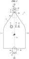
- FIG. 1 is a schematic top view of a marine vessel to which a marine propulsion system according to an example embodiment of the present teaching is provided.
- the marine vessel 1 includes a hull 2.
- a forward direction (bow direction) of the marine vessel 1 is indicated by an arrow FWD, and a backward direction (stern direction) is indicated by an arrow BWD.
- a starboard direction of the marine vessel 1 is indicated by an arrow R, and a port direction thereof is indicated by an arrow L.
- a center line C of the hull 2 passes through a center of a stern 2A and a tip of a bow 2B.
- the center line C passes through a center of gravity G (turning center) of the marine vessel 1.
- a front-back direction is a direction parallel to the center line C.
- a front is in a direction upward along the center line C shown in FIG. 1 (a direction toward the bow 2B viewed from the stern 2A).
- a back is in a direction downward along the center line C shown in FIG. 1 .
- the left-right direction is based on a case where the hull 2 is viewed from the back.
- An up-down direction is perpendicular to the front-back direction and the left-right direction.
- the marine vessel 1 includes a steerable outboard motor 4 (first propulsion device) and a steerable trolling motor 5 (second propulsion device) as propulsion devices that propel the hull 2.
- the outboard motor 4 is steerably disposed at the stern 2A
- the trolling motor 5 is steerably disposed at the bow 2B.
- the trolling motor 5 may be disposed at a predetermined position in front of the stern 2A of the hull 2, and the position of the trolling motor 5 is not limited to the bow 2B of the hull 2.
- the outboard motor 4 and the trolling motor 5 may be a main propulsion device and an auxiliary propulsion device, respectively, of the marine vessel 1.
- the single outboard motor 4 is provided at a central portion in the lateral direction of the stern 2A.
- the marine vessel 1 is provided with a steering (e.g., steering wheel) 11 operated mainly for steering, a throttle operator 12 operated mainly for output adjustment of the outboard motor 4, and a joystick 13 operated mainly for steering and output adjustment of the outboard motor 4.
- a steering e.g., steering wheel
- a throttle operator 12 operated mainly for output adjustment of the outboard motor 4
- a joystick 13 operated mainly for steering and output adjustment of the outboard motor 4.
- the layout of these components is not limited to the illustrated one.
- FIG. 2 is a schematic side view showing the bow portion and the stern portion of the marine vessel 1.
- the outboard motor 4 includes an outboard motor body 20.
- a propeller 21 and a skeg (rudder) 23 are disposed in a lower portion of the outboard motor body 20.
- the outboard motor body 20 is mounted to the stern 2A with a mounting mechanism 22.
- the mounting mechanism 22 includes a clamp bracket detachably fixed to the stern 2A and a swivel bracket coupled to the clamp bracket so as to be rotatable about a tilt shaft.
- the outboard motor body 20 is mounted to the swivel bracket so as to be rotatable about a steering axis center K ( FIG. 1 ).
- the steering angle of the outboard motor 4 is changed by rotating the outboard motor body 20 about the turning axis center K.
- the trolling motor 5 is an aftermarket device that can be externally attached to the already completed marine vessel 1 at a later time, unlike a bow thruster (not shown).
- the trolling motor 5 is able to apply a propulsion force to the hull 2 in any direction around a rotation axis J ( FIG. 1 ), which is the center line of a rotation shaft 52.
- the trolling motor 5 is electrically driven.
- the trolling motor 5 includes an electric motor 50 and a propeller 51 that is rotationally driven by the electric motor 50 to generate a propulsion force.
- the trolling motor 5 further includes the rotation shaft 52 extending upward from the electric motor 50 through the rotation axis J, and a bracket 53 fixed to the bow 2B and supporting the rotation shaft 52 rotatably around the rotation axis J.
- the electric motor 50 rotates around the rotation axis J integrally with the rotation shaft 52.
- An upper portion of the rotation shaft 52 protrudes upward from the bracket 53.
- An operation panel 54 including an indicator (not shown) indicating the direction of the propeller 51 in the water is provided at the upper end of the rotation shaft 52.
- the bracket 53 is provided with an operation unit (not shown), such as a foot pedal, for a user to directly operate the trolling motor 5.
- a wireless remote controller (not shown) for the user to operate the trolling motor 5 may be provided.
- the operation panel 54 is not shown in FIG. 1 .
- the trolling motor 5 includes, for example, an electric steering unit 56 that is built in the bracket 53 and rotates the rotation shaft 52 and the electric motor 50 around the rotation axis J, and an ECU (not shown) that is built in the operation panel 54 and controls the electric motor 50 and the steering unit 56.
- an electric steering unit 56 that is built in the bracket 53 and rotates the rotation shaft 52 and the electric motor 50 around the rotation axis J
- an ECU (not shown) that is built in the operation panel 54 and controls the electric motor 50 and the steering unit 56.
- the steering unit 56 includes, for example, a servo motor.
- the trolling motor 5 is able to change its direction by a steering operation by the steering unit 56.
- the steering unit 56 changes the direction of the propulsion force generated by the rotating propeller 51 by rotating the electric motor 50 about the rotation axis J to change the direction of the electric motor 50 within a range of 360 degrees or more. This changes the steering angle of the trolling motor 5, and the direction of the propulsion force applied to the hull 2 by the trolling motor 5 changes.
- the bracket 53 is vertically pivotable with respect to the hull 2 around a pivot shaft 59.
- the bracket 53 is rotated about the pivot shaft 59 so that the trolling motor 5 can be moved between a use position and a storage position.
- FIGS. 1 and 2 show a state in which the trolling motor 5 is in the use position. When the trolling motor 5 is in the use position, the electric motor 50 and the propeller 51 are located below a waterline (not shown).
- the plurality of maneuvering modes are roughly classified into an outboard motor mode in which the trolling motor 5 is not used and cooperation modes in which the trolling motor 5 and the outboard motor 4 are used in combination.
- the outboard motor mode is a maneuvering mode in which the outboard motor 4 is controlled mainly according to the rotation operation of the steering 11 and the operation of the throttle operator 12.
- a trolling motor mode (predetermined mode) can be designated as one of the cooperation modes.
- the trolling motor mode is a maneuvering mode that uses a propulsion force of the trolling motor 5 and does not generate a propulsion force of the outboard motor 4.
- the trolling motor mode includes a plurality of detailed modes, such as first to fourth modes as representative examples. Although the steering angle of the outboard motor 4 is controlled as necessary in some of the detailed modes, a propulsion force is not generated. Therefore, in the trolling motor mode, the outboard motor body 20 is steered as necessary, and the skeg 23 that is steered together with the outboard motor body 20 assists the turning of the hull 2. The outboard motor 4 generates no propulsion force and therefore is quiet. The turning property is increased by steering the skeg 23.
- the first to fourth modes will be described below with reference to FIG. 6 and the subsequent figures.
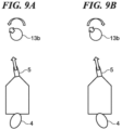
- FIG. 3 is a perspective view showing the joystick 13.
- the joystick 13 includes a main body 13a and a columnar stick 13b extending upward from the main body 13a.
- a stay point button 13c, a fish point button 13d, a drift button 13e, and a joystick button 13f are arranged on the main body 13a.
- the stay point button 13c receives an operation of switching ON and OFF of the Stay Point TM .
- the fish point button 13d receives an operation of switching ON and OFF of the Fish Point TM .
- the drift button 13e receives an operation of switching ON and OFF of the Drift Point TM .
- the joystick button 13f receives an operation of switching ON and OFF of the joystick mode.
- the Stay Point TM is one of the automatic maneuvering modes in which the heading of the bow 2B of the hull 2 is maintained at a set target heading and the position of the hull 2 is maintained at a set target point.
- the Fish Point TM is one of the automatic maneuvering modes in which the hull 2 is directed to a set target point by turning the hull 2 and the moving direction of the hull 2 is maintained toward the target point.
- the Drift Point TM is one of the automatic maneuvering modes in which the hull 2 is moved by receiving an external force including wind and current while maintaining the heading at the bow 2B of the hull 2 in the target heading by turning the hull 2. It is not essential that all of the above-mentioned buttons are mounted on the main body 13a.
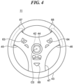
- FIG. 4 is a view showing the steering 11 viewed approximately from the front.
- the steering 11 includes a central portion 44, an annular wheel 43, and three spokes (a first spoke 45, a second spoke 46, and a third spoke 47).
- the steering 11 is supported by the hull 2 so as to be rotatable about a rotation fulcrum C0.
- the steering 11 includes a plurality of switches.
- a changeover switch 69, a left switch 63, and a right switch 64 are disposed on the surface of the steering 11.
- the steering 11 includes a left paddle 67 and a right paddle 68.
- the left paddle 67 and the right paddle 68 are pivotable in the front-back direction.
- the left paddle 67 and the right paddle 68 are operators to generate an instruction to provide the propulsion force to the hull 2 in the backward direction and the forward direction, respectively.
- a controller 70 changes the magnitude of the propulsion force in the backward direction according to a throttle opening angle of the left paddle 67 when the left paddle 68 is operated.
- the controller 70 changes the magnitude of the propulsion force in the forward direction according to a throttle opening angle of the right paddle 68 when the right paddle 68 is operated.
- the controller 70 controls the trolling motor 5 and the outboard motor 4 according to the operation signals of the switches 63 and 64 and the paddles 67 and 68.
- the joystick mode and the drive mode enable on-the-spot turning in addition to parallel motions including a lateral motion.
- the parallel motion means that the hull 2 moves in the horizontal direction without turning in a yaw direction about the center of gravity G ( FIG. 1 ).
- the lateral motion moves the hull 2 to the left or right without turning.
- Addition of the propulsion force in the front-back direction during the lateral motion enables the parallel motion of the hull 2 in an oblique direction (obliquely left, right, front, and back).
- the on-the-spot turning rotates the hull 2 in the yaw direction around the center of gravity G.
- the parallel motion and the turning may be applied in combination.
- the hull 2 moves in parallel to a direction in which the stick 13b is turned.
- the operations of the left switch 63 and the right switch 64 achieve left lateral motion and right lateral motion of the hull 2, respectively.
- the paddles 67 and 68 are operated, the hull 2 moves backward and forward, respectively.
- one of the paddles 67 and 68 is operated in parallel with the operation of the left switch 63 or the right switch 64, the hull 2 moves in parallel to an oblique direction because the forward or backward motion is added to the lateral motion.
- the stick 13b can be operated to twist (or rotate) around the axial center of the stick 13b.
- an instruction to turn (or veer) can be given by twisting the stick 13b.
- an instruction to turn (or veer) can be given by a rotation operation of the wheel 43.
- Energizing elements are provided about the tilting direction and the twisting direction of the stick 13b of the joystick 13, and the stick 13b is always biased to a neutral position. Therefore, when the user releases the stick 13b, the stick 13b automatically returns to the neutral position.
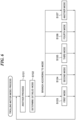
- FIG. 5 is a block diagram showing the marine propulsion system.
- the marine propulsion system includes a display unit 14, various sensors 15, the various operators 16, and a memory 17 in addition to the controller 70, the outboard motor 4, the trolling motor 5, the steering 11, the throttle operator 12, and the joystick 13.
- the controller 70 includes a CPU 71, a ROM 72, a RAM 73, and a timer (not shown).
- the ROM 72 stores control programs.
- the CPU 71 achieves various control processes by developing the control programs stored in the ROM 72 onto the RAM 73 and executing the control programs.
- the RAM 73 provides a work area in executing the control programs by the CPU 71.
- the various sensors 15 include a hull speed sensor, a hull acceleration sensor, a heading sensor, a distance sensor, a posture sensor, a position sensor, and a GNSS (Global Navigation Satellite System) sensor. Further, the various sensors 15 include a sensor to detect an operation of the throttle operator 12, a sensor to detect a rotational angular position of the steering 11, a sensor to detect an operation of each switch or paddle in the steering 11, and a sensor that detects an operation of the joystick 13.
- the hull speed sensor detects a speed (vessel speed) of the navigation of the marine vessel 1 (hull 2). The vessel speed may be obtained from a GNSS signal received by the GNSS sensor.
- the detection signals of the various sensors 15 are supplied to the controller 70.
- the various operators 16 include setting operators to perform various settings and input operators to input various instructions in addition to operators to perform operations related to the maneuvering. Some part of the various operators 16 may be arranged on the steering 11.
- the various operators 16 are operated by the user, and the operation signals are supplied to the controller 70.
- the memory 17 is preferably a readable and writable nonvolatile storage medium.
- the controller 70 may exchange information with the various sensors 15 and the various operators 16 by establishing predetermined communications.
- the display unit 14 displays various kinds of information.
- the outboard motor 4 includes an ECU (Engine Control Unit) 81, an SCU (Steering Control Unit) 82, an rpm sensor 83, an engine 84, a steering mechanism 85, various sensors 86, a steering angle sensor 87, and various actuators 88.
- Each of the ECU 81 and the SCU 82 includes a CPU (not shown).
- the ECU 81 controls the driving of the engine 84 according to an instruction from the controller 70.
- the SCU 82 controls the driving of the steering mechanism 85 according to an instruction from the controller 70.
- the steering mechanism 85 changes the direction of the outboard motor body 20 in the left-right direction by rotating the outboard motor body 20 about the steering axis center K ( FIG. 1 ). This changes the direction of the propulsion force acting on the stern 2A, which is the attachment position of the outboard motor body 20.
- the steering mechanism 85 may use an electric type or a hydraulic type.
- the various actuators 88 may include a power trim and tilt mechanism (PTT mechanism) that rotates the outboard motor 4 about a tilt axis.
- the rpm sensor 83 detects the number of rotations per unit time period of the engine 84.
- the various sensors 86 include a throttle opening sensor.
- the steering angle sensor 87 detects an actual steering angle of the outboard motor 4.
- the controller 70 may obtain the actual steering angle from a steering instruction value output to the steering mechanism 85.
- the trolling motor 5 includes an MCU (Motor Control Unit) 57, an SCU (Steering Control Unit) 58, a steering angle sensor 55, various sensors 60, and an actuator 61 in addition to the electric motor 50 and the steering unit 56.
- MCU Motor Control Unit
- SCU Steering Control Unit
- the MCU 57 and the SCU 58 include CPUs (not shown), respectively.
- the MCU 57 controls the driving of the electric motor 50 according to an instruction from the controller 70.
- the maximum output of the electric motor 50 may be less than the maximum output of the engine 84 of the outboard motor 4.
- the SCU 58 controls the driving of the steering unit 56 according to an instruction from the controller 70 to change the direction of the propulsion force acting on the bow 2B, which is the attachment position of the trolling motor 5.
- the actuator 61 moves the trolling motor 5 between the use position and the storage position. It is not essential to provide a function of moving the trolling motor 5 between the use position and the storage position by power.
- the steering angle sensor 55 detects the steering angle of the trolling motor 5 changed by the steering unit 56.
- the detection signals by the steering angle sensor 55 and the various sensors 60 are supplied to the controller 70. It is not essential that the outboard motor 4 and the trolling motor 5 include all of the above-described sensors and actuators.
- each propulsion motor acts on the point at which each propulsion motor is attached to the hull 2.
- the propulsion force of the trolling motor 5 acts on the bow 2B and the propulsion force of the outboard motor 4 acts on the position of the attachment mechanism 22 on the stern 2A for convenience of description.
- FIG. 6 is a flowchart showing a trolling motor mode process. This process is achieved by the CPU 71 loading a program stored in the ROM 72 onto the RAM 73 and executing the program. This process is started, for example, when the start of the trolling motor mode is instructed.
- a step S101 the controller 70 executes another process.
- the controller 70 executes switching of a detailed mode in the trolling motor mode based on a user instruction.
- the controller 70 ends this process.
- a step S102 the controller 70 determines a detailed mode and branches the process to one of steps S103 to S107 corresponding to the determined detailed mode.
- the trolling motor mode includes the first to fourth modes and another mode as the detailed modes.
- the controller 70 obtains a maneuvering instruction, controls the propulsion force of the trolling motor 5 based on the maneuvering instruction, and controls the steering angle of the skeg (rudder) 23 without generating the propulsion force of the outboard motor 4.
- the maneuvering instruction about the propulsion force, propulsion direction, turning, veering, or the like is input by an operation of the throttle operator 12, joystick 13, steering 11, various operators 16, or wireless remote controller for the trolling motor 5.
- the maneuvering instruction includes a steering instruction.
- the steering instruction includes an instruction, such as a propulsion direction, turning, or veering.
- the trolling motor mode can be applied in combination with the joystick mode, drive mode, or automatic maneuvering mode.
- the maneuvering instruction is input by the operation of the joystick 13.
- the controller 70 defining and functioning as an obtaining unit obtains the propulsion direction from the tilting direction of the stick 13b and obtains the required propulsion force from the tilting angle of the stick 13b. Also, the controller 70 obtains the steering instruction, such as turning (or veering), from a twisting operation amount of the stick 13b.
- the controller 70 as the obtaining unit obtains the maneuvering instruction from an operation of one of the wheel 43, first operation instruction members, and second operation instruction members, or a combination of two or more operations of them.
- the switches 63 and 64 correspond to the first operation instruction members to generate an instruction to provide a propulsion force in the lateral direction to the hull 2.
- the paddles 67 and 68 correspond to the second operation instruction members to generate an instruction to provide a propulsion force in the front-back direction to the hull 2.
- the target heading is input by a combination of operations of the switches 63 and 64 and the paddles 67 and 68, and the required propulsion force is input by a combination of operation amounts of them.
- a steering instruction such as turning or veering, is input by a rotational operation of the wheel 43.
- the maneuvering instructions issued in the case where the automatic maneuvering mode is simultaneously applied also include an instruction generated by a determination of the controller 70.
- the controller 70 controls the propulsion force and the steering angle of the trolling motor 5 according to the tilting operation of the stick 13b and controls the steering angle of the skeg 23 according to the twisting operation of the stick 13b in the other mode.
Landscapes
- Chemical & Material Sciences (AREA)
- Engineering & Computer Science (AREA)
- Combustion & Propulsion (AREA)
- Mechanical Engineering (AREA)
- Ocean & Marine Engineering (AREA)
- Mechanical Control Devices (AREA)
Applications Claiming Priority (1)
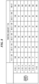
| Application Number | Priority Date | Filing Date | Title |
|---|---|---|---|
| JP2023130808A JP2025025728A (ja) | 2023-08-10 | 2023-08-10 | 船舶推進システムおよびその制御方法、船舶 |
Publications (1)
| Publication Number | Publication Date |
|---|---|
| EP4516659A1 true EP4516659A1 (de) | 2025-03-05 |
Family
ID=92208775
Family Applications (1)
| Application Number | Title | Priority Date | Filing Date |
|---|---|---|---|
| EP24192323.4A Pending EP4516659A1 (de) | 2023-08-10 | 2024-08-01 | Schiffsantriebssystem, steuerungsverfahren dafür und wasserfahrzeug |
Country Status (3)
| Country | Link |
|---|---|
| US (1) | US20250050996A1 (de) |
| EP (1) | EP4516659A1 (de) |
| JP (1) | JP2025025728A (de) |
Citations (3)
| Publication number | Priority date | Publication date | Assignee | Title |
|---|---|---|---|---|
| US20130072076A1 (en) * | 2010-02-09 | 2013-03-21 | Zf Friedrichshafen Ag | Method for maneuvering a yacht |
| US9988134B1 (en) | 2016-12-12 | 2018-06-05 | Brunswick Corporation | Systems and methods for controlling movement of a marine vessel using first and second propulsion devices |
| US20220126963A1 (en) * | 2020-10-22 | 2022-04-28 | Yamaha Hatsudoki Kabushiki Kaisha | Vessel operation system and vessel |
Family Cites Families (3)
| Publication number | Priority date | Publication date | Assignee | Title |
|---|---|---|---|---|
| CH705329A2 (de) * | 2011-07-16 | 2013-01-31 | Peter A Mueller | Manövrieranlage für Wasserfahrzeuge. |
| JP2024032427A (ja) * | 2022-08-29 | 2024-03-12 | スズキ株式会社 | 操船システム、制御パラメータの設定方法 |
| BE1031742B1 (nl) * | 2023-06-27 | 2025-02-04 | Ppa Electronics | Vaartuig met een inrichting voor het aansturen van een voortstuwingsmotor en/of één of meer stuurmiddelen van het schip |
-
2023
- 2023-08-10 JP JP2023130808A patent/JP2025025728A/ja active Pending
-
2024
- 2024-07-22 US US18/779,415 patent/US20250050996A1/en active Pending
- 2024-08-01 EP EP24192323.4A patent/EP4516659A1/de active Pending
Patent Citations (3)
| Publication number | Priority date | Publication date | Assignee | Title |
|---|---|---|---|---|
| US20130072076A1 (en) * | 2010-02-09 | 2013-03-21 | Zf Friedrichshafen Ag | Method for maneuvering a yacht |
| US9988134B1 (en) | 2016-12-12 | 2018-06-05 | Brunswick Corporation | Systems and methods for controlling movement of a marine vessel using first and second propulsion devices |
| US20220126963A1 (en) * | 2020-10-22 | 2022-04-28 | Yamaha Hatsudoki Kabushiki Kaisha | Vessel operation system and vessel |
Also Published As
| Publication number | Publication date |
|---|---|
| JP2025025728A (ja) | 2025-02-21 |
| US20250050996A1 (en) | 2025-02-13 |
Similar Documents
| Publication | Publication Date | Title |
|---|---|---|
| JP5481059B2 (ja) | 操船支援装置およびそれを備えた船舶 | |
| JP5371401B2 (ja) | 操船支援装置およびそれを備えた船舶 | |
| JP2006001432A (ja) | 小型船舶用ステアリング装置 | |
| EP4516658A1 (de) | Schiffsantriebssystem, steuerungsverfahren dafür und wasserfahrzeug | |
| EP4089004A2 (de) | System zum manövrieren von schiffen | |
| US12459628B2 (en) | Marine propulsion system and marine vessel | |
| US20230140720A1 (en) | Marine propulsion system and marine vessel | |
| JP2024068486A (ja) | 船舶推進システムおよびそれを備える船舶 | |
| EP4516659A1 (de) | Schiffsantriebssystem, steuerungsverfahren dafür und wasserfahrzeug | |
| EP4206071B1 (de) | Schiffsantriebssystem | |
| CA3180824C (en) | Marine propulsion system and marine vessel with motorized forward-rearward movement | |
| EP4520648A1 (de) | Schiffsantriebssystem, steuerungsverfahren dafür und wasserfahrzeug | |
| EP4177152A1 (de) | Schiffsantriebssystem | |
| JP7684833B2 (ja) | 船舶の航行システム | |
| US20250050990A1 (en) | Marine propulsion system, control method therefor, and marine vessel | |
| JP2022114058A (ja) | 船舶の旋回制御装置 | |
| JP2022146791A (ja) | 操船システム及び船舶 | |
| US12486014B2 (en) | Marine propulsion system and marine vessel | |
| US20250236374A1 (en) | Boat control system and boat | |
| US20250236380A1 (en) | Boat control system and boat | |
| EP4524023B1 (de) | Schiffsantriebssystem zur bewegung eines wasserfahrzeugs in seitlicher richtung und steuerungsverfahren dafür | |
| US12221200B2 (en) | Marine vessel maneuvering system and marine vessel | |
| US20250236379A1 (en) | Boat control system and boat | |
| JP2022146792A (ja) | 操船システム及び船舶 |
Legal Events
| Date | Code | Title | Description |
|---|---|---|---|
| PUAI | Public reference made under article 153(3) epc to a published international application that has entered the european phase |
Free format text: ORIGINAL CODE: 0009012 |
|
| STAA | Information on the status of an ep patent application or granted ep patent |
Free format text: STATUS: THE APPLICATION HAS BEEN PUBLISHED |
|
| AK | Designated contracting states |
Kind code of ref document: A1 Designated state(s): AL AT BE BG CH CY CZ DE DK EE ES FI FR GB GR HR HU IE IS IT LI LT LU LV MC ME MK MT NL NO PL PT RO RS SE SI SK SM TR |
|
| STAA | Information on the status of an ep patent application or granted ep patent |
Free format text: STATUS: REQUEST FOR EXAMINATION WAS MADE |
|
| P01 | Opt-out of the competence of the unified patent court (upc) registered |
Free format text: CASE NUMBER: UPC_APP_1589_4516659/2025 Effective date: 20250731 |
|
| 17P | Request for examination filed |
Effective date: 20250822 |
|
| STAA | Information on the status of an ep patent application or granted ep patent |
Free format text: STATUS: EXAMINATION IS IN PROGRESS |
|
| 17Q | First examination report despatched |
Effective date: 20260128 |