EP3965541A1 - Gehäuse und elektronische vorrichtung - Google Patents
Gehäuse und elektronische vorrichtung Download PDFInfo
- Publication number
- EP3965541A1 EP3965541A1 EP20822550.8A EP20822550A EP3965541A1 EP 3965541 A1 EP3965541 A1 EP 3965541A1 EP 20822550 A EP20822550 A EP 20822550A EP 3965541 A1 EP3965541 A1 EP 3965541A1
- Authority
- EP
- European Patent Office
- Prior art keywords
- receiving area
- electronic component
- electronic device
- heat
- housing
- Prior art date
- Legal status (The legal status is an assumption and is not a legal conclusion. Google has not performed a legal analysis and makes no representation as to the accuracy of the status listed.)
- Withdrawn
Links
- 230000001681 protective effect Effects 0.000 claims abstract description 64
- 230000017525 heat dissipation Effects 0.000 claims abstract description 31
- 239000010410 layer Substances 0.000 claims description 13
- OKTJSMMVPCPJKN-UHFFFAOYSA-N Carbon Chemical compound [C] OKTJSMMVPCPJKN-UHFFFAOYSA-N 0.000 claims description 6
- 229910002804 graphite Inorganic materials 0.000 claims description 6
- 239000010439 graphite Substances 0.000 claims description 6
- 239000012790 adhesive layer Substances 0.000 claims description 5
- 239000002184 metal Substances 0.000 claims description 5
- 229910052751 metal Inorganic materials 0.000 claims description 5
- 238000012545 processing Methods 0.000 claims description 5
- 238000004891 communication Methods 0.000 abstract description 7
- 238000013021 overheating Methods 0.000 abstract description 6
- 238000010438 heat treatment Methods 0.000 abstract description 2
- 239000012071 phase Substances 0.000 description 8
- 239000007791 liquid phase Substances 0.000 description 6
- 239000000463 material Substances 0.000 description 6
- RYGMFSIKBFXOCR-UHFFFAOYSA-N Copper Chemical compound [Cu] RYGMFSIKBFXOCR-UHFFFAOYSA-N 0.000 description 5
- 238000009833 condensation Methods 0.000 description 5
- 230000005494 condensation Effects 0.000 description 5
- 238000001704 evaporation Methods 0.000 description 5
- 230000008020 evaporation Effects 0.000 description 5
- 238000000034 method Methods 0.000 description 5
- 239000011889 copper foil Substances 0.000 description 4
- 238000010586 diagram Methods 0.000 description 4
- 230000008569 process Effects 0.000 description 4
- 238000012546 transfer Methods 0.000 description 4
- 230000001413 cellular effect Effects 0.000 description 3
- 230000000694 effects Effects 0.000 description 3
- 238000011160 research Methods 0.000 description 3
- XEEYBQQBJWHFJM-UHFFFAOYSA-N Iron Chemical compound [Fe] XEEYBQQBJWHFJM-UHFFFAOYSA-N 0.000 description 2
- 238000012986 modification Methods 0.000 description 2
- 230000004048 modification Effects 0.000 description 2
- 239000000853 adhesive Substances 0.000 description 1
- 230000001070 adhesive effect Effects 0.000 description 1
- 150000001298 alcohols Chemical class 0.000 description 1
- 229910052802 copper Inorganic materials 0.000 description 1
- 239000010949 copper Substances 0.000 description 1
- 238000013461 design Methods 0.000 description 1
- 238000001514 detection method Methods 0.000 description 1
- 238000011161 development Methods 0.000 description 1
- 238000004512 die casting Methods 0.000 description 1
- 238000006073 displacement reaction Methods 0.000 description 1
- 238000005530 etching Methods 0.000 description 1
- 239000003292 glue Substances 0.000 description 1
- 230000006872 improvement Effects 0.000 description 1
- 238000009434 installation Methods 0.000 description 1
- 229910052742 iron Inorganic materials 0.000 description 1
- 238000002955 isolation Methods 0.000 description 1
- 230000007257 malfunction Effects 0.000 description 1
- 239000011148 porous material Substances 0.000 description 1
- 238000000926 separation method Methods 0.000 description 1
- 238000005245 sintering Methods 0.000 description 1
- 230000007480 spreading Effects 0.000 description 1
- 238000012360 testing method Methods 0.000 description 1
- XLYOFNOQVPJJNP-UHFFFAOYSA-N water Substances O XLYOFNOQVPJJNP-UHFFFAOYSA-N 0.000 description 1
Images


Classifications
-
- H—ELECTRICITY
- H05—ELECTRIC TECHNIQUES NOT OTHERWISE PROVIDED FOR
- H05K—PRINTED CIRCUITS; CASINGS OR CONSTRUCTIONAL DETAILS OF ELECTRIC APPARATUS; MANUFACTURE OF ASSEMBLAGES OF ELECTRICAL COMPONENTS
- H05K7/00—Constructional details common to different types of electric apparatus
- H05K7/20—Modifications to facilitate cooling, ventilating, or heating
- H05K7/2029—Modifications to facilitate cooling, ventilating, or heating using a liquid coolant with phase change in electronic enclosures
- H05K7/20336—Heat pipes, e.g. wicks or capillary pumps
-
- H—ELECTRICITY
- H05—ELECTRIC TECHNIQUES NOT OTHERWISE PROVIDED FOR
- H05K—PRINTED CIRCUITS; CASINGS OR CONSTRUCTIONAL DETAILS OF ELECTRIC APPARATUS; MANUFACTURE OF ASSEMBLAGES OF ELECTRICAL COMPONENTS
- H05K5/00—Casings, cabinets or drawers for electric apparatus
- H05K5/0086—Casings, cabinets or drawers for electric apparatus portable, e.g. battery operated apparatus
-
- H—ELECTRICITY
- H05—ELECTRIC TECHNIQUES NOT OTHERWISE PROVIDED FOR
- H05K—PRINTED CIRCUITS; CASINGS OR CONSTRUCTIONAL DETAILS OF ELECTRIC APPARATUS; MANUFACTURE OF ASSEMBLAGES OF ELECTRICAL COMPONENTS
- H05K7/00—Constructional details common to different types of electric apparatus
- H05K7/20—Modifications to facilitate cooling, ventilating, or heating
- H05K7/2039—Modifications to facilitate cooling, ventilating, or heating characterised by the heat transfer by conduction from the heat generating element to a dissipating body
- H05K7/20436—Inner thermal coupling elements in heat dissipating housings, e.g. protrusions or depressions integrally formed in the housing
-
- H—ELECTRICITY
- H05—ELECTRIC TECHNIQUES NOT OTHERWISE PROVIDED FOR
- H05K—PRINTED CIRCUITS; CASINGS OR CONSTRUCTIONAL DETAILS OF ELECTRIC APPARATUS; MANUFACTURE OF ASSEMBLAGES OF ELECTRICAL COMPONENTS
- H05K7/00—Constructional details common to different types of electric apparatus
- H05K7/20—Modifications to facilitate cooling, ventilating, or heating
- H05K7/20954—Modifications to facilitate cooling, ventilating, or heating for display panels
- H05K7/2099—Liquid coolant with phase change
Definitions
- the protective member is arranged opposite or in contact with the electronic component provided in the first receiving area.
- the heat generated by the first electronic component is transferred, through the protective member and the heat-conducting element, to other locations of the electronic device, and then is dissipated to the outside. Accordingly, the heat balance of the electronic device is achieved, and the local overheating of the electronic device is avoided, thereby improving the heat dissipation efficiency of the electronic device.
- the protective member it is possible to prevent the battery from being damaged by the heat-conducting element when the heat-conducting element is dislocated, thereby improving the reliability of the electronic device.
- the inventor continues to study how to prevent the dislocation of the heat pipe and thus protect the battery without changing the thickness of the electronic device, so as to realize the heat balance and heat dissipation of the electronic device, thereby improving the heat dissipation performance of the electronic device.
- the inventor has researched how to avoid the dislocation of the heat pipe in the electronic device, how to make the positions of the heat pipe and the battery relatively fixed, how to make the heat dissipation structure dissipate the heat rapidly in the electronic device, and so on.
- the inventor further conducted research on how to design a heat dissipation structure that enables heat balance in the electronic device, and thus proposed the technical solutions of the embodiments of the present disclosure.
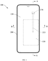
- the electronic device 100 includes a housing 200, a display panel 130, a first electronic component 150, and a second electronic component 170.
- the housing 200 and the display panel 130 cooperatively define a receiving cavity, and the first electronic component 150 and the second electronic component 170 are accommodated in the receiving cavity.
- the housing 200 can provide protection for the first electronic component 150 and the second electronic component 170, to prevent the first electronic component 150 and the second electronic component 170 from being dislocated or damaged under the impact of an external force, thereby prolonging the service life of the electronic device 100.
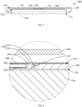
- the protective member 250 is arranged opposite or in contact with the first electronic component 150 provided in the first receiving area 211. As such, the heat generated by the first electronic component 150 is transferred, through the protective member 250 and the heat-conducting element 230, to other locations of the electronic device 100, and then is dissipated to the outside. Accordingly, the heat balance of the electronic device 100 is achieved, and the local overheating of the electronic device 100 is avoided, thereby improving the heat dissipation efficiency of the electronic device 100.
- the middle frame 210 is configured to install or carry the first electronic component 150 and the second electronic component 170 to limit the positions of the first electronic component 150 and the second electronic component 170, thereby avoiding malfunction of the electronic device 100 from being caused by the displacement of the first electronic component150 and the second electronic component 170.
- the first surface 212 may serve as the bottom wall of the first receiving area 211 and the second receiving area 215, so that the first electronic component 150 received in the first receiving area 211 and the second electronic component 170 received in the second receiving area 215 are further confined.
- the first receiving area 211 and the second receiving area 215 may be located on opposite sides of the middle frame 210.
- the first receiving area 211 is provided on the first surface 212
- the second receiving area 215 is provided on the second surface 214.
- the protective member 250 is disposed in the accommodating groove 213, and spans across the first receiving area 211 and the second receiving area 215.
- the two opposite ends of the protective member 250 are respectively located at the first receiving area 211 and the second receiving area 215, to cover an opening formed by the accommodating groove 213 in the first receiving area 211 and an opening formed by the accommodating groove 213 in the second receiving area 215.
- the protective member includes two bent parts 253 respectively connected to opposite sides of the main body 251, and each of the two bent parts is superposed on a respective one of the two mounting parts 219, thereby improving the protection to the heat-conducting element 230. Further, by limiting the position of the protective member 250 through the two end surfaces 2191 of the two mounting parts 219, the protective member 250 can be prevented from shaking when the protective member 250 is accommodated in the accommodating groove 213.
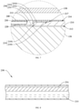
- the heat-conducting element 230 is accommodated in the accommodating groove 213, and is disposed on a side of the protective member 250 that is away from the first electronic component 150.
- the heat-conducting element 230 is opposite to the main body 251, and the bent part 253 limits the position of the heat-conducting element 230.
- opposite ends of the heat-conducting element 230 are located at positions corresponding to the first receiving area 211 and the second receiving area 215, respectively, so that the heat-conducting element 230 can balance the heat of the first receiving area 211 and the heat of the second receiving area 215.
- the capillary layer 231 may be an independent element, for example, the capillary layer 231 is a metal weaved mesh which is connected to the inner surface of the heat-conducting element 230 by means of sintering or the like. Also optionally, the capillary layer 231 may be a tiny structure formed on the inner surface of the heat-conducting element 230 by etching or the like.
- the working process of the heat-conducting element 230 is explained by taking a case where an end of the heat-conducting element 230 close to the second electronic component 170 is an evaporation end, and an end thereof close to the first electronic component 150 is a condensation end, as an example.
- the working medium 233 in the liquid phase absorbs the heat and evaporates at the evaporation end, and becomes the working medium 233 in the gas phase to move and spread toward the condensation end.
Landscapes
- Engineering & Computer Science (AREA)
- Microelectronics & Electronic Packaging (AREA)
- Physics & Mathematics (AREA)
- Thermal Sciences (AREA)
- Cooling Or The Like Of Electrical Apparatus (AREA)
Applications Claiming Priority (2)
| Application Number | Priority Date | Filing Date | Title |
|---|---|---|---|
| CN201910508109.9A CN110167322B (zh) | 2019-06-12 | 2019-06-12 | 壳体及电子设备 |
| PCT/CN2020/088868 WO2020248744A1 (zh) | 2019-06-12 | 2020-05-07 | 壳体及电子设备 |
Publications (2)
| Publication Number | Publication Date |
|---|---|
| EP3965541A1 true EP3965541A1 (de) | 2022-03-09 |
| EP3965541A4 EP3965541A4 (de) | 2022-06-15 |
Family
ID=67628881
Family Applications (1)
| Application Number | Title | Priority Date | Filing Date |
|---|---|---|---|
| EP20822550.8A Withdrawn EP3965541A4 (de) | 2019-06-12 | 2020-05-07 | Gehäuse und elektronische vorrichtung |
Country Status (4)
| Country | Link |
|---|---|
| US (1) | US11641728B2 (de) |
| EP (1) | EP3965541A4 (de) |
| CN (1) | CN110167322B (de) |
| WO (1) | WO2020248744A1 (de) |
Families Citing this family (8)
| Publication number | Priority date | Publication date | Assignee | Title |
|---|---|---|---|---|
| CN110167322B (zh) * | 2019-06-12 | 2021-02-02 | Oppo广东移动通信有限公司 | 壳体及电子设备 |
| CN110730600B (zh) * | 2019-10-29 | 2021-01-29 | 维沃移动通信有限公司 | 电子设备的壳体及电子设备 |
| CN111432598B (zh) * | 2020-03-04 | 2022-05-24 | Oppo广东移动通信有限公司 | 电子设备的壳体组件及电子设备 |
| WO2021190552A1 (zh) * | 2020-03-24 | 2021-09-30 | 华为技术有限公司 | 移动终端及中框组件 |
| CN113038797B (zh) * | 2021-03-12 | 2023-04-07 | 维沃移动通信有限公司 | 电子设备 |
| CN113260228B (zh) * | 2021-05-14 | 2022-12-06 | 维沃移动通信有限公司 | 电子设备 |
| TWM630195U (zh) * | 2022-03-04 | 2022-08-01 | 藍天電腦股份有限公司 | 散熱結構 |
| CN117432704A (zh) * | 2023-11-23 | 2024-01-23 | Oppo广东移动通信有限公司 | 折叠装置、折叠壳体及电子设备 |
Family Cites Families (10)
| Publication number | Priority date | Publication date | Assignee | Title |
|---|---|---|---|---|
| TWM522552U (zh) * | 2013-07-19 | 2016-05-21 | 超眾科技股份有限公司 | 手持通訊裝置及其薄型化散熱器 |
| CN204482215U (zh) | 2015-04-15 | 2015-07-15 | 青岛海信移动通信技术股份有限公司 | 一种手机散热结构 |
| CN106304817B (zh) * | 2015-06-04 | 2019-01-18 | 宏碁股份有限公司 | 电子装置 |
| CN105578840B (zh) * | 2015-07-31 | 2018-06-15 | 宇龙计算机通信科技(深圳)有限公司 | 一种移动终端 |
| US20170367219A1 (en) * | 2016-06-16 | 2017-12-21 | Asia Vital Components Co., Ltd. | Vapor chamber structure |
| CN106207038B (zh) * | 2016-08-30 | 2020-01-24 | Oppo广东移动通信有限公司 | 电池保护件及其制作方法以及移动通信终端 |
| CN109219307B (zh) * | 2017-06-30 | 2021-08-17 | 深圳富泰宏精密工业有限公司 | 散热结构及具有该散热结构的电子装置 |
| CN108777255B (zh) * | 2018-06-11 | 2020-07-31 | Oppo广东移动通信有限公司 | 一种散热组件及电子设备 |
| CN108646891A (zh) * | 2018-06-11 | 2018-10-12 | Oppo广东移动通信有限公司 | 一种散热组件以及电子装置 |
| CN110167322B (zh) * | 2019-06-12 | 2021-02-02 | Oppo广东移动通信有限公司 | 壳体及电子设备 |
-
2019
- 2019-06-12 CN CN201910508109.9A patent/CN110167322B/zh not_active Expired - Fee Related
-
2020
- 2020-05-07 WO PCT/CN2020/088868 patent/WO2020248744A1/zh not_active Ceased
- 2020-05-07 EP EP20822550.8A patent/EP3965541A4/de not_active Withdrawn
-
2021
- 2021-11-24 US US17/535,169 patent/US11641728B2/en active Active
Also Published As
| Publication number | Publication date |
|---|---|
| US20220087067A1 (en) | 2022-03-17 |
| EP3965541A4 (de) | 2022-06-15 |
| US11641728B2 (en) | 2023-05-02 |
| CN110167322A (zh) | 2019-08-23 |
| CN110167322B (zh) | 2021-02-02 |
| WO2020248744A1 (zh) | 2020-12-17 |
Similar Documents
| Publication | Publication Date | Title |
|---|---|---|
| US11641728B2 (en) | Housing and electronic device | |
| US8325483B2 (en) | Electronic device including a heat conduction member | |
| AU2016244055B2 (en) | Electronic device including an externally-mounted heat pipe | |
| CN212164015U (zh) | 移动终端、中框组件及散热组件 | |
| CN105723821A (zh) | 便携式电子设备的冷却构造 | |
| WO2021018004A1 (zh) | 一种导热装置及终端设备 | |
| CN210183778U (zh) | 壳体及电子设备 | |
| CN212851549U (zh) | 散热件及电子设备 | |
| EP1732230B1 (de) | Tragbares elektronisches Gerät | |
| CN219876700U (zh) | 中框组件及电子设备 | |
| CN110267491B (zh) | 中框组件及电子设备 | |
| CN211429879U (zh) | 一种移动终端 | |
| CN110278688B (zh) | 壳体组件及电子设备 | |
| JP2003142864A (ja) | 電子装置 | |
| JP7541570B2 (ja) | 携帯端末 | |
| CN107333448A (zh) | 摄像头组件及电子设备 | |
| CN208432827U (zh) | 显示屏组件及电子设备 | |
| CN212413240U (zh) | 按键组件和电子设备 | |
| JP2010072904A (ja) | 電子機器、および熱輸送部材 | |
| WO2021190552A1 (zh) | 移动终端及中框组件 | |
| CN113453479B (zh) | 移动终端及中框组件 | |
| CN210130059U (zh) | 散热装置及电子设备 | |
| CN110149784A (zh) | 散热组件及电子设备 | |
| CN101473710B (zh) | 电子设备 | |
| CN210381726U (zh) | 壳体组件及电子设备 |
Legal Events
| Date | Code | Title | Description |
|---|---|---|---|
| STAA | Information on the status of an ep patent application or granted ep patent |
Free format text: STATUS: THE INTERNATIONAL PUBLICATION HAS BEEN MADE |
|
| PUAI | Public reference made under article 153(3) epc to a published international application that has entered the european phase |
Free format text: ORIGINAL CODE: 0009012 |
|
| STAA | Information on the status of an ep patent application or granted ep patent |
Free format text: STATUS: REQUEST FOR EXAMINATION WAS MADE |
|
| 17P | Request for examination filed |
Effective date: 20211202 |
|
| AK | Designated contracting states |
Kind code of ref document: A1 Designated state(s): AL AT BE BG CH CY CZ DE DK EE ES FI FR GB GR HR HU IE IS IT LI LT LU LV MC MK MT NL NO PL PT RO RS SE SI SK SM TR |
|
| A4 | Supplementary search report drawn up and despatched |
Effective date: 20220517 |
|
| RIC1 | Information provided on ipc code assigned before grant |
Ipc: H05K 7/20 20060101AFI20220511BHEP |
|
| DAV | Request for validation of the european patent (deleted) | ||
| DAX | Request for extension of the european patent (deleted) | ||
| GRAP | Despatch of communication of intention to grant a patent |
Free format text: ORIGINAL CODE: EPIDOSNIGR1 |
|
| STAA | Information on the status of an ep patent application or granted ep patent |
Free format text: STATUS: GRANT OF PATENT IS INTENDED |
|
| INTG | Intention to grant announced |
Effective date: 20240307 |
|
| STAA | Information on the status of an ep patent application or granted ep patent |
Free format text: STATUS: THE APPLICATION HAS BEEN WITHDRAWN |
|
| 18W | Application withdrawn |
Effective date: 20240409 |