EP3962247B1 - Steuergerät - Google Patents
Steuergerät Download PDFInfo
- Publication number
- EP3962247B1 EP3962247B1 EP21172858.9A EP21172858A EP3962247B1 EP 3962247 B1 EP3962247 B1 EP 3962247B1 EP 21172858 A EP21172858 A EP 21172858A EP 3962247 B1 EP3962247 B1 EP 3962247B1
- Authority
- EP
- European Patent Office
- Prior art keywords
- housing
- circuit carrier
- housing element
- heat
- elements
- Prior art date
- Legal status (The legal status is an assumption and is not a legal conclusion. Google has not performed a legal analysis and makes no representation as to the accuracy of the status listed.)
- Active
Links
Images




Classifications
-
- G—PHYSICS
- G01—MEASURING; TESTING
- G01S—RADIO DIRECTION-FINDING; RADIO NAVIGATION; DETERMINING DISTANCE OR VELOCITY BY USE OF RADIO WAVES; LOCATING OR PRESENCE-DETECTING BY USE OF THE REFLECTION OR RERADIATION OF RADIO WAVES; ANALOGOUS ARRANGEMENTS USING OTHER WAVES
- G01S19/00—Satellite radio beacon positioning systems; Determining position, velocity or attitude using signals transmitted by such systems
- G01S19/01—Satellite radio beacon positioning systems transmitting time-stamped messages, e.g. GPS [Global Positioning System], GLONASS [Global Orbiting Navigation Satellite System] or GALILEO
- G01S19/13—Receivers
- G01S19/35—Constructional details or hardware or software details of the signal processing chain
-
- H—ELECTRICITY
- H05—ELECTRIC TECHNIQUES NOT OTHERWISE PROVIDED FOR
- H05K—PRINTED CIRCUITS; CASINGS OR CONSTRUCTIONAL DETAILS OF ELECTRIC APPARATUS; MANUFACTURE OF ASSEMBLAGES OF ELECTRICAL COMPONENTS
- H05K1/00—Printed circuits
- H05K1/02—Details
- H05K1/0201—Thermal arrangements, e.g. for cooling, heating or preventing overheating
- H05K1/0203—Cooling of mounted components
-
- H—ELECTRICITY
- H05—ELECTRIC TECHNIQUES NOT OTHERWISE PROVIDED FOR
- H05K—PRINTED CIRCUITS; CASINGS OR CONSTRUCTIONAL DETAILS OF ELECTRIC APPARATUS; MANUFACTURE OF ASSEMBLAGES OF ELECTRICAL COMPONENTS
- H05K1/00—Printed circuits
- H05K1/02—Details
- H05K1/0213—Electrical arrangements not otherwise provided for
- H05K1/0237—High frequency adaptations
- H05K1/0243—Printed circuits associated with mounted high frequency components
-
- H—ELECTRICITY
- H05—ELECTRIC TECHNIQUES NOT OTHERWISE PROVIDED FOR
- H05K—PRINTED CIRCUITS; CASINGS OR CONSTRUCTIONAL DETAILS OF ELECTRIC APPARATUS; MANUFACTURE OF ASSEMBLAGES OF ELECTRICAL COMPONENTS
- H05K1/00—Printed circuits
- H05K1/18—Printed circuits structurally associated with non-printed electric components
- H05K1/181—Printed circuits structurally associated with non-printed electric components associated with surface mounted components
-
- H—ELECTRICITY
- H05—ELECTRIC TECHNIQUES NOT OTHERWISE PROVIDED FOR
- H05K—PRINTED CIRCUITS; CASINGS OR CONSTRUCTIONAL DETAILS OF ELECTRIC APPARATUS; MANUFACTURE OF ASSEMBLAGES OF ELECTRICAL COMPONENTS
- H05K5/00—Casings, cabinets or drawers for electric apparatus
- H05K5/0026—Casings, cabinets or drawers for electric apparatus provided with connectors and printed circuit boards [PCB], e.g. automotive electronic control units
- H05K5/0043—Casings, cabinets or drawers for electric apparatus provided with connectors and printed circuit boards [PCB], e.g. automotive electronic control units comprising a frame housing mating with two lids wherein the PCB is flat mounted on the frame housing
-
- H—ELECTRICITY
- H05—ELECTRIC TECHNIQUES NOT OTHERWISE PROVIDED FOR
- H05K—PRINTED CIRCUITS; CASINGS OR CONSTRUCTIONAL DETAILS OF ELECTRIC APPARATUS; MANUFACTURE OF ASSEMBLAGES OF ELECTRICAL COMPONENTS
- H05K5/00—Casings, cabinets or drawers for electric apparatus
- H05K5/0026—Casings, cabinets or drawers for electric apparatus provided with connectors and printed circuit boards [PCB], e.g. automotive electronic control units
- H05K5/0047—Casings, cabinets or drawers for electric apparatus provided with connectors and printed circuit boards [PCB], e.g. automotive electronic control units having a two-part housing enclosing a PCB
- H05K5/0052—Casings, cabinets or drawers for electric apparatus provided with connectors and printed circuit boards [PCB], e.g. automotive electronic control units having a two-part housing enclosing a PCB characterized by joining features of the housing parts
-
- H—ELECTRICITY
- H05—ELECTRIC TECHNIQUES NOT OTHERWISE PROVIDED FOR
- H05K—PRINTED CIRCUITS; CASINGS OR CONSTRUCTIONAL DETAILS OF ELECTRIC APPARATUS; MANUFACTURE OF ASSEMBLAGES OF ELECTRICAL COMPONENTS
- H05K5/00—Casings, cabinets or drawers for electric apparatus
- H05K5/0026—Casings, cabinets or drawers for electric apparatus provided with connectors and printed circuit boards [PCB], e.g. automotive electronic control units
- H05K5/0047—Casings, cabinets or drawers for electric apparatus provided with connectors and printed circuit boards [PCB], e.g. automotive electronic control units having a two-part housing enclosing a PCB
- H05K5/0056—Casings, cabinets or drawers for electric apparatus provided with connectors and printed circuit boards [PCB], e.g. automotive electronic control units having a two-part housing enclosing a PCB characterized by features for protecting electronic components against vibration and moisture, e.g. potting, holders for relatively large capacitors
-
- H—ELECTRICITY
- H05—ELECTRIC TECHNIQUES NOT OTHERWISE PROVIDED FOR
- H05K—PRINTED CIRCUITS; CASINGS OR CONSTRUCTIONAL DETAILS OF ELECTRIC APPARATUS; MANUFACTURE OF ASSEMBLAGES OF ELECTRICAL COMPONENTS
- H05K5/00—Casings, cabinets or drawers for electric apparatus
- H05K5/0026—Casings, cabinets or drawers for electric apparatus provided with connectors and printed circuit boards [PCB], e.g. automotive electronic control units
- H05K5/0047—Casings, cabinets or drawers for electric apparatus provided with connectors and printed circuit boards [PCB], e.g. automotive electronic control units having a two-part housing enclosing a PCB
- H05K5/006—Casings, cabinets or drawers for electric apparatus provided with connectors and printed circuit boards [PCB], e.g. automotive electronic control units having a two-part housing enclosing a PCB characterized by features for holding the PCB within the housing
-
- H—ELECTRICITY
- H05—ELECTRIC TECHNIQUES NOT OTHERWISE PROVIDED FOR
- H05K—PRINTED CIRCUITS; CASINGS OR CONSTRUCTIONAL DETAILS OF ELECTRIC APPARATUS; MANUFACTURE OF ASSEMBLAGES OF ELECTRICAL COMPONENTS
- H05K5/00—Casings, cabinets or drawers for electric apparatus
- H05K5/02—Details
- H05K5/0247—Electrical details of casings, e.g. terminals, passages for cables or wiring
-
- H—ELECTRICITY
- H05—ELECTRIC TECHNIQUES NOT OTHERWISE PROVIDED FOR
- H05K—PRINTED CIRCUITS; CASINGS OR CONSTRUCTIONAL DETAILS OF ELECTRIC APPARATUS; MANUFACTURE OF ASSEMBLAGES OF ELECTRICAL COMPONENTS
- H05K5/00—Casings, cabinets or drawers for electric apparatus
- H05K5/02—Details
- H05K5/03—Covers
-
- H—ELECTRICITY
- H05—ELECTRIC TECHNIQUES NOT OTHERWISE PROVIDED FOR
- H05K—PRINTED CIRCUITS; CASINGS OR CONSTRUCTIONAL DETAILS OF ELECTRIC APPARATUS; MANUFACTURE OF ASSEMBLAGES OF ELECTRICAL COMPONENTS
- H05K5/00—Casings, cabinets or drawers for electric apparatus
- H05K5/10—Casings, cabinets or drawers for electric apparatus comprising several parts forming a closed casing
- H05K5/15—Casings, cabinets or drawers for electric apparatus comprising several parts forming a closed casing assembled by resilient members
-
- H—ELECTRICITY
- H05—ELECTRIC TECHNIQUES NOT OTHERWISE PROVIDED FOR
- H05K—PRINTED CIRCUITS; CASINGS OR CONSTRUCTIONAL DETAILS OF ELECTRIC APPARATUS; MANUFACTURE OF ASSEMBLAGES OF ELECTRICAL COMPONENTS
- H05K7/00—Constructional details common to different types of electric apparatus
- H05K7/20—Modifications to facilitate cooling, ventilating, or heating
- H05K7/20845—Modifications to facilitate cooling, ventilating, or heating for automotive electronic casings
- H05K7/20854—Heat transfer by conduction from internal heat source to heat radiating structure
-
- H—ELECTRICITY
- H05—ELECTRIC TECHNIQUES NOT OTHERWISE PROVIDED FOR
- H05K—PRINTED CIRCUITS; CASINGS OR CONSTRUCTIONAL DETAILS OF ELECTRIC APPARATUS; MANUFACTURE OF ASSEMBLAGES OF ELECTRICAL COMPONENTS
- H05K2201/00—Indexing scheme relating to printed circuits covered by H05K1/00
- H05K2201/10—Details of components or other objects attached to or integrated in a printed circuit board
- H05K2201/10007—Types of components
- H05K2201/10151—Sensor
Definitions
- the invention relates to a control device, such as is used in particular as a component of a navigation system or for automated driving in motor vehicles.
- a control device is designed to process both information that is fed to the control device as input signals via an HF (high frequency) antenna cable and information from sensors arranged in particular within the control device in order to determine the exact position of the control device or the vehicle. This makes use of the knowledge that precise navigation is only possible due to the combination of satellite-based information and information from internal sensors.
- An electrical or electronic circuit arranged within such a control device is characterized in that it has at least one heat-generating component that is arranged on a circuit carrier, in particular in the form of a circuit board.
- the at least one sensor element is arranged on the same or on another circuit carrier or circuit board.
- control unit In order to influence the functionality of the at least one sensor element as little as possible, it is essential that the heat from the heat-generating component is conducted out of the control unit as effectively as possible.
- a heat-conducting element made of metal is used for this purpose.
- the electrical contact of such a control unit is made by means of a plug connection body, which carries connection elements that serve to electrically contact the at least one circuit carrier.
- the control units known from the prior art are, from a manufacturing point of view or for reasons as far as possible, low manufacturing costs.
- the requirements for such control units are particularly high when they are used for automated driving, where the vehicle is driven without driver intervention.
- safe functioning and thus, for example, reliable heat dissipation from heat-generating components is particularly important.
- control device which has an outer casing made of metal, which, in addition to a shielding effect, also serves to dissipate heat from at least one heat-generating component. Furthermore, the known control device has several sensor elements which are arranged in a separate inner casing. From the US 2006/089019 A1 and the EP 1 677 583 A1 Other control units comprising sensor elements are known, in which a heat-generating component is arranged at a distance from an outer housing of the control unit, which in turn acts as a heat-conducting element.
- a control device is known with a heat-generating element arranged on a first circuit board, which is thermally connected to a housing base, and vibration damping elements between the circuit board and the housing cover.
- the documents DE 195 44 974 C1 and EP 0 312 740 A1 show control units with a circuit carrier and a pressure sensor.
- the invention is based on the object of optimizing a control device which is designed both to process (high-frequency) signals and to accommodate at least one sensor element, from a manufacturing point of view and for reasons of keeping manufacturing costs as low as possible.
- the heat-conducting element is arranged as an insert in a housing element consisting essentially of plastic, that the housing element has a connecting region for connecting the housing element to a carrier element, and that the heat-conducting element is thermally connected to the connecting region.
- a body-side carrier element is usually made of metal at least in parts and therefore enables rapid and good dissipation of heat from the control unit.
- the at least one heat-generating component and at least one sensor element are arranged on different circuit carriers, wherein the circuit carrier for the at least one sensor element is arranged in a vibration-damped manner.
- Such a structural design has the particular advantage that the heat transfer from the at least one heat-generating component can take place via a relatively rigid connection between the circuit carrier, which carries the at least one heat-generating component, and the heat-conducting element, while on the other hand the at least one sensor element can be arranged in a vibration-damped manner within the control unit via the second circuit carrier.
- the circuit carrier carrying the at least one sensor element is electrically connected exclusively to the circuit carrier carrying the at least one heat-generating component, preferably by means of a mechanically floating connection.
- the circuit carrier carrying the at least one sensor element there is preferably no electrical contact with the circuit carrier carrying the at least one sensor element via electrical connection elements or connection pins arranged in particular on the housing, which otherwise promote the transmission of vibrations from the housing to the circuit carrier carrying the at least one sensor.
- circuit carrier carrying the at least one sensor element may be mechanically connected to the circuit carrier carrying the at least one heat-generating component via connecting elements arranged in a housing element.
- the heat conducting element according to the claimed invention is provided by a housing element made of metal, in the form of the housing base.
- the heat-conducting element has a relatively high heat storage capacity and radiation surface even without thermal coupling to a carrier element, so that particularly rapid and effective cooling of the heat-generating component is possible.
- the housing base forming the housing element is designed as a deep-drawn part, preferably made of sheet metal, and that the housing base has an elevation or indentation in the overlap area with the at least one heat-generating component, which is thermally coupled to the circuit carrier for the at least one heat-generating component or to the heat-generating component.
- Such thermal coupling of the circuit carrier or the component is usually carried out in the form of a thermally conductive adhesive.
- a frame-shaped housing element is closed by a plastic cover. This reduces the housing volume required when using two circuit carriers, in particular, as a result of an advantageous manufacturing step sequence.
- the contacts between the electrical connection elements and the at least one circuit carrier are formed via press-in connections.
- the control unit 10 is used in particular as a component of a navigation system or a system for determining the location of the control unit 10 in a motor vehicle (not shown).
- the control unit 10 processes both signals which are fed to the control unit 10 as an input variable via a (high frequency) antenna cable (not shown) and signals from the control unit 10 arranged within the control unit 10.
- Sensors such as pressure sensors, yaw rate sensors, magnetic field sensors or similar.
- the first control unit 10 has a housing 13 consisting of two housing elements 11, 12.
- the housing element 11 forms a housing base, while the housing element 12 is designed in the shape of a lid or hood and, when connected to the housing element 11, forms an interior space 14 for accommodating two separate circuit carriers 16, 17, for example in the form of printed circuit boards.
- the housing element 12 has two flange-like protruding fastening sections 18, 19 with through-openings 20 formed therein. When the two housing elements 11, 12 are assembled, the through-openings 20 are arranged in overlap with through-openings 21 on the housing element 11.
- the housing 13 can be fastened to a carrier element 25, for example a metal body part, which is only shown symbolically and in a partial area, using fastening elements not shown, in particular fastening screws.
- the housing element 11 can have two pin-shaped positioning elements 26, 27 with a different cross-section on the underside facing away from the housing element 12 ( Fig. 2 ), which interact with corresponding openings on the support element 25 (not shown).
- the housing element 11 is made of plastic and is preferably designed as an injection-molded part. It has a raised portion 28, in the area of which the housing element 11 extends further into the interior 14 than in the other areas of the housing element 11. It can also be seen that a heat-conducting element 30 made of metal is arranged in the material of the housing element 11, which is at least partially overmolded by the material of the housing element 11 and which extends into the area of at least one through-opening 21 of the housing element 11. In the Fig. 2 is that Heat conducting element 30 is shown partially cut away for better visibility. In particular, based on the representation of the Fig.1 It can also be seen that the heat conducting element 30 in the area of the through-opening 21 is flush with the top or bottom of the housing element 11. This enables heat flow or heat dissipation via the heat conducting element 30 in the direction of the carrier element 25 when the housing 13 is fastened using fastening screws, which are usually made of metal.
- the heat-conducting element 30 interacts with the underside of the first circuit carrier 16 via a heat-conducting adhesive 31.
- Electrical or electronic components 1 are arranged on the first circuit carrier 16, with at least one of the components 1 being a heat-generating component 1, the heat of which can be dissipated from the interior 14 of the housing 13 during operation via the heat-conducting element 30.
- the elevation 28 is arranged in the area of the first circuit carrier 16 in which the heat-generating component 1 is also located.
- the first circuit carrier 16 rests on the housing element 11 on a preferably circumferential elevation 32, for example made of silicone, which projects from the housing element 11 in the direction of the first circuit carrier 16 and is preferably elastic.
- a plug connection body 35 is provided on the second housing element 12, which is also made of plastic and is designed as an injection-molded part.
- the plug connection body 35 is formed by overmolding electrical connection elements 36 with plastic material, whereby the connection elements 36 can be designed to be customer-specific or application-specific.
- at least one of the connection elements 36 is designed as a high-frequency connection, for example in the form of a high-frequency socket, via which a high-frequency signal is fed to at least one of the circuit carriers 16, 17 as an input variable.
- the plug connection body 35 can, as shown, be designed as a component separate from the housing element 12 or as an integral part of the housing element 12.
- connection to the Housing element 12 can be carried out by overmolding the plug connection body 35 with the material of the housing element 12 or in some other way, for example via a (sealed) adhesive connection.
- connection elements 36 are designed to make contact with the first circuit carrier 16.
- they have connection areas 37 that protrude in the direction of the first circuit carrier 16 and are designed to interact with corresponding openings in the first circuit carrier 16 in order to form a press-in connection.
- a further connection element 38 ( Fig.1 ) is shown, which also engages in a corresponding opening formed in the first circuit carrier 16 to form a press fit or press connection, and serves to further stabilize or fix the first circuit carrier 16 in the housing element 11 in the assembled state.
- the second circuit carrier 17 Parallel to and in relation to the housing element 11 on the side of the first circuit carrier 16 facing away from the housing element 11 is the second circuit carrier 17, also designed as a circuit board.
- the second circuit carrier 17 has, in addition to further electrical or electronic components 2, which preferably generate at least substantially no heat, at least one sensor element 40, 41, which in the illustrated embodiment are arranged on the side of the second circuit carrier 17 facing away from the first circuit carrier 16.
- the one sensor element 40 is designed as a pressure sensor, for example, and in the installed state is surrounded or enclosed in the circumferential direction by a housing wall 42 of the housing element 12.
- the housing element 12 In order to transmit the external pressure to the sensor element 40, the housing element 12 is provided with an opening 43 in the overlap area with the sensor element 40, in the area of which a pressure membrane 44 is arranged, which enables the external pressure to be transmitted to the sensor element 40.
- the second circuit carrier 17 is connected to the housing 13 (mechanically) essentially only via the housing element 12.
- the housing element 12 has fastening elements 45 which project in the direction of the second circuit carrier 17 and which interact with corresponding openings in the second circuit carrier 17. It is important that the fastening elements 45 are at least indirectly designed as vibration-damping fastening elements 45.
- the fastening elements 45 consist of a soft or elastic material, so that vibrations transmitted via the housing element 12 or the housing 13 are transmitted in a dampened manner to the circuit carrier 17 carrying the at least one sensor element 40, 41.
- the fastening elements 45 are rigid, but the corresponding fastening openings on the second circuit carrier 17, which interact with the fastening elements 45, have vibration-damping properties, for example in the form of an elastic coating or an elastic element.
- the two circuit carriers 16, 17 are connected to one another with an electrical plug connection 46, which enables an electrical connection between the components 2 or the sensor elements 40, 41 of the circuit carrier 17 with the components 1 of the circuit carrier 16. It is essential that the plug connection 46 is designed as a mechanically floating plug connection 46, i.e. that at least essentially no vibrations are transmitted from the circuit carrier 16 to the circuit carrier 17 via the plug connection 46.
- the two housing elements 11, 12 of the housing 13 are connected to one another by means of a snap-in or clip connection 48.
- the housing element 11 for example, has a circumferential seal 49, which in the embodiment works together with a projection or similar formed on the housing element 12 in overlap with the seal 49.
- a screw connection between the two housing elements 11, 12 is of course also possible (not shown).
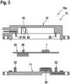
- the second control device 10a shown which also does not correspond to the claimed invention, differs from the control device 10 in that only a single circuit board 52 is provided, which carries both the at least one heat-generating component 1 and the at least one sensor element 40.
- the vibration damping between the circuit board 52 and the housing 13 is brought about by the circuit board 52 being mounted on at least one element 53 arranged on the housing element 11 and consisting of an elastic material such as silicone.
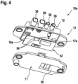
- the circuit board 52 is used to form two circuit carriers 16a, 17a, as can be seen from the Fig.4 is symbolically shown, in the area of the at least one sensor element 40 has through holes, slots 54 or the like, which separate the area in which the at least one sensor element 40 is arranged on the circuit board 52 for forming the second circuit carrier 17a from the areas of the circuit board 52 which form the first circuit carrier 16a with the components 1.
- the connection between the two circuit carriers 16a, 17a on the circuit board 52 is thus only made in certain areas.
- the third control device 10b shown has a first housing element 61 in the form of a housing base, which is made of metal, in particular sheet metal, and is formed using a deep-drawing process.
- the first housing element 61 has a raised area 62 which is thermally coupled to the underside of a circuit carrier 64 designed as a printed circuit board via a thermally conductive adhesive 63.
- the housing element 61 thus itself acts to dissipate heat in the direction of the carrier element 25 (not shown).
- On the circuit carrier 64 in analogy to the printed circuit board 52 in the second control device 10a, there are both the components 1, of which at least one of the components 1 is designed as a heat-generating component 1, and at least one sensor element 40.
- the raised region 62 or the thermally conductive adhesive 63 is arranged in the overlap region with the at least one heat-generating component 1.
- the first housing element 61 interacts with a second housing element 65 made of plastic, which is in the form of a frame or sleeve and in which the connection elements 66 for electrical (and mechanical) contacting of the circuit carrier 64 are also arranged.
- the connection between the two housing elements 61, 65 is made via a snap-in or riveted connection, for which purpose corresponding projections 67 or corresponding openings 68 are formed on the two housing elements 61, 65.
- the sealing between the two housing elements 61, 65 is made via a sealing element 69 arranged between the two housing elements 61, 65.
- a structural unit made from the two housing elements 61, 65 can be connected to the circuit carrier 64 in that the circuit carrier 64 is designed to form a press-in connection with the connection elements 66 and additional connecting elements 71, wherein the circuit carrier 64 is introduced from above in the direction of the housing element 61 into the area of the housing element 65. Furthermore, in analogy to the second control device 10a, it can be provided that the circuit carrier 64 has vibration damping measures in the area of the at least one sensor element 40 by means of corresponding recesses or slots etc. (not shown), which reduce or diminish the transmission of vibrations via the housing elements 61, 65 to the sensor element 40.
- the second housing element 65 can be closed on the side facing away from the first housing element 61 by means of a housing cover made of plastic, which forms a third housing element 72.
- the connection between the two housing elements 64, 72 is made in a manner known per se, for example via an adhesive connection or a (laser) weld seam, with media tightness between the housing elements 65, 72 being ensured by means of conventional technologies.
- the components of the Fig.7 differ from the components of the control unit 10b according to the Fig.5 and 6 essentially in that the two housing elements 65, 72 are replaced by a one-piece, cover- or hood-shaped housing element 75.
- the housing element 75 is also made of plastic and is manufactured using an injection molding process.
- the fourth control device 10c is manufactured by connecting the circuit carrier 64 to the connection elements 66 and the connecting elements 71, which form a press-in connection.
- the assembly consisting of the circuit carrier 64 and the housing element 75 is then connected to the first housing element 61 made of metal, which in particular also enables the heat dissipation of the at least one heat-generating heating element 1.
- the at least one sensor element 40 is arranged on the side of the circuit carrier 64 facing the housing element 61, for which purpose a corresponding opening 43 and pressure membrane 44 are formed in the housing element 61.
- the components of a fifth control unit 10d are shown.
- the structure of the fifth control unit 10d essentially corresponds to that of the third control unit 10b according to the Fig.5 and 6
- the control unit 10d has two circuit carriers 81, 82 designed as printed circuit boards. While the first circuit carrier 81 carries the at least one heat-generating component 1, the second circuit carrier 82 carries the at least one sensor element 40.
- the second circuit carrier 82 is mechanically connected to the second housing element 65 and also electrically to the first circuit carrier 81 via pin-like connecting elements 83 arranged on the second housing element 65, which form a press-in connection.
- Vibration damping elements 85 for example made of silicone, are arranged on the cover-shaped third housing element 72 on the side facing the second circuit carrier 82, which cause vibration damping of vibrations transmitted to the second circuit carrier 82 via the second housing element 65.
- control device 10b to 10d described so far can be modified or altered in many different ways without departing from the invention as defined in the appended claims.
Landscapes
- Engineering & Computer Science (AREA)
- Microelectronics & Electronic Packaging (AREA)
- Physics & Mathematics (AREA)
- Radar, Positioning & Navigation (AREA)
- Remote Sensing (AREA)
- Thermal Sciences (AREA)
- General Physics & Mathematics (AREA)
- Computer Networks & Wireless Communication (AREA)
- Signal Processing (AREA)
- Cooling Or The Like Of Electrical Apparatus (AREA)
- Casings For Electric Apparatus (AREA)
- Mounting Of Printed Circuit Boards And The Like (AREA)
- Cooling Or The Like Of Semiconductors Or Solid State Devices (AREA)
Description
- Die Erfindung betrifft ein Steuergerät, wie es insbesondere als Bestandteil eines Navigationssystems oder zum automatisierten Fahren in Kraftfahrzeugen verwendet wird. Ein derartiges Steuergerät ist dazu ausgebildet, sowohl Informationen, welche über ein HF (Hochfrequenz)-Antennenkabel als Eingangssignale an das Steuergerät zugeführt werden, als auch Informationen von insbesondere innerhalb des Steuergeräts angeordneten Sensoren zu verarbeiten, um die genaue Position des Steuergeräts bzw. des Fahrzeugs zu ermitteln. Hierbei wird sich die Erkenntnis zunutze gemacht, dass eine exakte Navigation nur aufgrund der Kombination von satellitengestützten Informationen und Informationen von internen Sensoren möglich ist. Eine innerhalb eines derartigen Steuergeräts angeordnete elektrische bzw. elektronische Schaltung zeichnet sich dadurch aus, dass sie wenigstens ein wärmeerzeugendes Bauteil aufweist, das auf einem Schaltungsträger, insbesondere in Form von einer Leiterplatte, angeordnet ist. Darüber hinaus ist auf demselben oder aber auf einem anderen Schaltungsträger bzw. Leiterplatte das wenigstens eine Sensorelement angeordnet. Um insbesondere die Funktionalität des wenigstens einen Sensorelements möglichst wenig zu beeinflussen, ist es wesentlich, dass die Wärme von dem wärmeerzeugenden Bauteil möglichst effektiv aus dem Steuergerät ausgeleitet wird. Hierzu dient in der Praxis ein aus Metall bestehendes Wärmeleitelement. Darüber hinaus erfolgt die elektrische Kontaktierung eines derartigen Steuergeräts mittels eines Steckeranschlusskörpers, der Anschlusselemente trägt, die der elektrischen Kontaktierung des wenigstens einen Schaltungsträgers dienen. Insbesondere für den Großserieneinsatz sind die aus dem Stand der Technik bekannten Steuergeräte aus fertigungstechnischer Sicht bzw. aus Gründen möglichst geringer Herstellkosten noch nicht optimal ausgebildet. Darüber hinaus sind die Anforderungen an derartige Steuergeräte besonders hoch, wenn sie zum automatisierten Fahren benutzt werden, bei dem ein Fahren des Fahrzeugs ohne Fahrereingriff erfolgt. Hier ist eine sichere Funktion und damit beispielsweise eine zuverlässige Wärmeabfuhr von wärmeerzeugenden Bauteilen besonders wichtig.
- Aus der
DE 199 21 692 A1 ist ein Steuergerät, bekannt, das ein aus Metall bestehendes Außengehäuse aufweist, das neben einer Abschirmwirkung gleichzeitig der Wärmeableitung wenigstens eines wärmeerzeugenden Bauteils dient. Weiterhin weist das bekannte Steuergerät mehrere Sensorelemente auf, die in einem separaten Innengehäuse angeordnet sind. Aus derUS 2006/089019 A1 und derEP 1 677 583 A1 sind weitere, Sensorelemente umfassende Steuergeräte bekannt, bei denen jeweils ein wärmeerzeugendes Bauteil beabstandet zu einem Außengehäuse des Steuergeräts angeordnet ist, welches wiederum in Art eines Wärmeleitelements wirkt. Aus derDE 10 2013 206999 A1 ist ein Steuergerät mit einem auf einer ersten Leiterplatte angeordneten wärmeerzeugenden Element, das thermisch mit einem Gehäuseboden verbunden ist, und Vibrationsdämpfungselementen zwischen der Leiterplatte und dem Gehäusedeckel bekannt. Die DokumenteDE 195 44 974 C1 undEP 0 312 740 A1 zeigen Steuergeräte mit einem Schaltungsträger und einem Drucksensor. - Ausgehend von dem dargestellten Stand der Technik liegt der Erfindung die Aufgabe zugrunde, ein Steuergerät, welches dazu ausgebildet ist, sowohl (Hochfrequenz-)Signale zu verarbeiten als auch der Aufnahme wenigstens eines Sensorelements dient, aus herstellungstechnischer Sicht sowie aus Gründen möglichst geringer Herstellkosten zu optimieren.
- Diese Aufgabe wird erfindungsgemäß bei einem Steuergerät mit den Merkmalen des Anspruchs 1 gelöst.
- Vorteilhafte Weiterbildungen des erfindungsgemäßen Steuergeräts sind in den Unteransprüchen aufgeführt.
- In einer ersten, nicht der beanspruchten Erfindung entsprechenden konstruktiven Ausgestaltung, die ein besonders niedriges Gewicht des Gehäuses des Steuergeräts ermöglicht, wird vorgeschlagen, dass das Wärmeleitelement als Einlegeteil in einem im Wesentlichen aus Kunststoff bestehenden Gehäuseelement angeordnet ist, dass das Gehäuseelement einen Verbindungsbereich zur Verbindung des Gehäuseelements mit einem Trägerelement aufweist, und dass das Wärmeleitelement thermisch mit dem Verbindungsbereich verbunden ist. Mit anderen Worten gesagt bedeutet dies, dass die Wärmeleitung über das Wärmeleitelement in den Bereich einer Befestigungsstelle mit einem Trägerelement erfolgt, wobei durch die Ankopplung des Wärmeleitelements an den Verbindungsbereich eine optimale Übertragung der Wärme von dem Steuergerät an das Trägerelement erfolgt. Üblicherweise besteht ein derartiges, karosserieseitiges Trägerelement zumindest bereichsweise aus Metall und ermöglicht daher eine rasche und gute Ableitung der Wärme von dem Steuergerät.
- Um einerseits die Aufgabe einer möglichst effektiven Wärmeableitung zu ermöglichen, und andererseits die Funktionalität des wenigstens einen Sensorelements zu gewährleisten bzw. zu verbessern, insbesondere mit Blick auf das Sensorelement einwirkende Vibrationen, wird vorgeschlagen, dass das wenigstens eine wärmeerzeugende Bauteil und dass wenigstens eine Sensorelement auf unterschiedlichen Schaltungsträgern angeordnet sind, wobei der Schaltungsträger für das wenigstens eine Sensorelement vibrationsgedämpft angeordnet ist. Eine derartige konstruktive Ausbildung hat insbesondere den Vorteil, dass die Wärmeübertragung von dem wenigstens einen wärmeerzeugenden Bauteil über eine relativ starre Verbindung zwischen dem Schaltungsträger, der das wenigstens eine wärmeerzeugende Bauteil trägt, und dem Wärmeleitelement erfolgen kann, während andererseits das wenigstens eine Sensorelement über den zweiten Schaltungsträger vibrationsgedämpft innerhalb des Steuergeräts angeordnet werden kann.
- Zur Optimierung der Schwingungsentkopplung des wenigstens einen Sensorelements ist es in Weiterbildung des zuletzt gemachten Vorschlags vorgesehen, dass der das wenigstens eine Sensorelement tragende Schaltungsträger ausschließlich mit dem das wenigstens eine wärmeerzeugende Bauteil tragenden Schaltungsträger elektrisch verbunden ist, vorzugsweise durch eine mechanisch schwimmende Verbindung. Es findet somit bevorzugt keine elektrische Kontaktierung des das wenigstens eine Sensorelement tragenden Schaltungsträgers über insbesondere am Gehäuse angeordnete elektrische Anschlusselemente bzw. Anschlusspins statt, die ansonsten eine Übertragung von Vibrationen von dem Gehäuse an den den wenigstens einen Sensor tragenden Schaltungsträger begünstigen.
- Alternativ hierzu ist es jedoch aus Gründen einer verbesserten Wärmeentkopplung zwischen den beiden Schaltungsträgern auch möglich, dass der das wenigstens eine Sensorelement tragende Schaltungsträger mit dem das wenigstens eine wärmeerzeugende Bauteil tragenden Schaltungsträger über in einem Gehäuseelement angeordnete Verbindungselemente mechanisch verbunden ist.
- Eine besonders gute Wärmeabfuhr wird bewirkt, wenn das Wärmeleitelement gemäss der beanspruchten Erfindung durch ein aus Metall bestehendes Gehäuseelement, in Form des Gehäusebodens gebildet ist. Dadurch weist das Wärmeleitelement auch ohne thermische Ankopplung an ein Trägerelement eine relativ hohe Wärmespeicherkapazität sowie Abstrahlfläche auf, sodass eine besonders rasche und effektive Abkühlung des wärmerzeugenden Bauteils ermöglicht wird. In fertigungstechnisch bevorzugter Ausgestaltung des zuletzt gemachten Vorschlags ist es vorgesehen, dass der das Gehäuseelement bildende Gehäuseboden als Tiefziehteil, vorzugsweise aus Blech bestehend, ausgebildet ist, und dass der Gehäuseboden im Überdeckungsbereich mit dem wenigstens einen wärmeerzeugenden Bauteil eine Erhöhung bzw. Einformung aufweist, die thermisch mit dem Schaltungsträger für das wenigstens eine wärmeerzeugende Bauteil oder dem wärmeerzeugenden Bauteil gekoppelt ist. Eine derartige thermische Kopplung des Schaltungsträgers bzw. des Bauteils erfolgt dabei üblicherweise in Form eines Wärmeleitklebers.
- Aus fertigungstechnischer Sicht ist es besonders vorteilhaft, wenn beim Vorhandensein eines rahmenförmigen Gehäuseelements dieses von einem aus Kunststoff bestehenden Deckel verschlossen ist. Dadurch wird insbesondere das benötigte Gehäusevolumen bei Verwendung von zwei Schaltungsträgern infolge einer vorteilhaften Fertigungsschrittfolge reduziert.
- Darüber hinaus ist es aus Fertigungs- bzw. Kostengründen besonders vorteilhaft, wenn die Kontaktierungen zwischen den elektrischen Anschlusselementen und dem wenigstens einen Schaltungsträger über Einpressverbindungen ausgebildet sind.
- Weitere Vorteile, Merkmale und Einzelheiten der Erfindung ergeben sich aus der nachfolgenden Beschreibung bevorzugter Ausführungsbeispiele sowie anhand der Zeichnung.
- Diese zeigt in:
-
Fig. 1 die Bauteile eines ersten, nicht erfindungsgemässen Steuergeräts in einem vereinfachten Längsschnitt, -
Fig. 2 die Bauteile des Steuergeräts derFig. 1 in teilweise montiertem Zustand in einer perspektivischen Unteransicht, -
Fig. 3 die Bauteile eines zweiten, nicht erfindungsgemässen Steuergeräts in einem vereinfachten Längsschnitt, -
Fig. 4 die Bauteile des zweiten Steuergeräts in einer perspektivischen Unteransicht, -
Fig. 5 die Bauteile eines dritten Steuergeräts in einem vereinfachten Längsschnitt, -
Fig. 6 die Bauteile des Steuergeräts des dritten Steuergeräts in einer perspektivischen Oberansicht, -
Fig. 7 die Bauteile eines vierten Steuergeräts in einem vereinfachten Längsschnitt und -
Fig. 8 die Bauteile eines fünften Steuergeräts in einem Längsschnitt. - Gleiche Elemente bzw. Elemente mit gleicher Funktion sind in den Figuren mit den gleichen Bezugsziffern versehen.
- In den
Fig. 1 und2 sind die Bauteile eines ersten Steuergeräts 10, das nicht der beanspruchten Erfindung entspricht, dargestellt. - Das Steuergerät 10 findet insbesondere Verwendung als Bestandteil eines Navigationssystems bzw. eines Systems zur Feststellung des Orts des Steuergeräts 10 in einem nicht dargestellten Kraftfahrzeug. Hierbei verarbeitet das Steuergerät 10 sowohl Signale, welche über ein nicht dargestelltes (Hochfrequenz)Antennenkabel als Eingangsgröße dem Steuergerät 10 zugeführt werden, als auch Signale von innerhalb des Steuergeräts 10 angeordneten Sensoren, beispielsweise Drucksensoren, Gierratensensoren, Magnetfeldsensoren oder ähnlichen.
- Das erste Steuergerät 10 weist ein aus zwei Gehäuseelementen 11, 12 bestehendes Gehäuse 13 auf. Das Gehäuseelement 11 bildet einen Gehäuseboden aus, während das Gehäuseelement 12 deckel- bzw. haubenförmig ausgebildet ist und bei mit dem Gehäuseelement 11 verbundenem Zustand einen Innenraum 14 zur Aufnahme zweier separater, beispielhaft als Leiterplatten ausgebildeter Schaltungsträger 16, 17 ausbildet. Das Gehäuseelement 12 weist zwei flanschartig abstehende Befestigungsabschnitte 18, 19 mit darin ausgebildeten Durchgangsöffnungen 20 auf. Die Durchgangsöffnungen 20 sind im montierten Zustand der beiden Gehäuseelemente 11, 12 in Überdeckung mit Durchgangsöffnungen 21 am Gehäuseelement 11 angeordnet. Mittels nicht dargestellter Befestigungselemente, insbesondere mittels Befestigungsschrauben, lässt sich das Gehäuse 13 an einem lediglich symbolisch und in einem Teilbereich dargestellten Trägerelement 25, beispielsweise einem metallischen Karosserieteil, befestigen.
- Zur lagerichtigen Positionierung des Gehäuses 13 zum Trägerelement 25 kann das Gehäuseelement 11 auf der dem Gehäuseelement 12 abgewandten Unterseite zwei, einen unterschiedlichen Querschnitt aufweisende, zapfenförmige Positionierelemente 26, 27 aufweisen (
Fig. 2 ), die mit entsprechenden Öffnungen am Trägerelement 25 zusammenwirken (nicht dargestellt). - Das Gehäuseelement 11 besteht aus Kunststoff und ist vorzugsweise als Spritzgussteil ausgebildet. Es weist eine Erhebung 28 auf, in deren Bereich das Gehäuseelement 11 weiter in den Innenraum 14 hineinragt als in den anderen Bereichen des Gehäuseelements 11. Weiterhin erkennt man, dass in dem Material des Gehäuseelements 11 ein aus Metall bestehendes Wärmeleitelement 30 angeordnet ist, welches von dem Material des Gehäuseelements 11 zumindest bereichsweise umspritzt ist, und das bis in den Bereich wenigstens einer Durchgangsöffnung 21 des Gehäuseelements 11 ragt. In der
Fig. 2 ist das Wärmeleitelement 30 der Besseren Erkennbarkeit wegen teilweise freigeschnitten dargestellt. Insbesondere anhand der Darstellung derFig. 1 erkennt man darüber hinaus, dass das Wärmeleitelement 30 im Bereich der Durchgangsöffnung 21 bündig mit der Oberseite bzw. Unterseite des Gehäuseelements 11 abschließt. Dadurch wird bei einer Befestigung des Gehäuses 13 über üblicherweise aus Metall bestehende Befestigungsschrauben als Befestigungselemente ein Wärmefluss bzw. eine Wärmeableitung über das Wärmeleitelement 30 in Richtung des Trägerelements 25 ermöglicht. - Das Wärmeleitelement 30 wirkt über einen Wärmeleitkleber 31 mit der Unterseite des ersten Schaltungsträgers 16 zusammen. Auf dem ersten Schaltungsträger 16 sind elektrische bzw. elektronische Bauteile 1 angeordnet, wobei wenigstens eines der Bauteile 1 ein wärmeerzeugendes Bauteil 1 ist, dessen Wärme über das Wärmeleitelement 30 aus dem Innenraum 14 des Gehäuses 13 während des Betriebs abgeleitet werden kann. Hierzu ist es vorgesehen, dass die Erhebung 28 in demjenigen Bereich des ersten Schaltungsträgers 16 angeordnet ist, in dessen Bereich sich auch das wärmeerzeugende Bauteil 1 befindet. Der erste Schaltungsträger 16 liegt im Einbauzustand auf dem Gehäuseelement 11 an einer vorzugsweise umlaufenden, von dem Gehäuseelement 11 in Richtung zum ersten Schaltungsträger 16 ragenden, vorzugsweise elastischen Erhebung 32, beispielsweise aus Silikon bestehend, auf.
- An dem zweiten Gehäuseelement 12, welches ebenfalls aus Kunststoff besteht und als Spritzgussteil ausgebildet ist, ist ein Steckeranschlusskörper 35 vorgesehen. Der Steckeranschlusskörper 35 wird durch Umspritzen von elektrischen Anschlusselementen 36 mit Kunststoffmaterial gebildet, wobei die Anschlusselemente 36 kunden- bzw. anwendungsspezifisch ausgebildet sein können. Insbesondere ist wenigstens einer der Anschlusselemente 36 als Hochfrequenzanschluss, zum Beispiel in Form einer Hochfrequenzbuchse ausgebildet, über den ein Hochfrequenzsignal an wenigstens einen der Schaltungsträger 16, 17 als Eingangsgröße zugeführt. Der Steckeranschlusskörper 35 kann, wie dargestellt, als von dem Gehäuseelement 12 separates Bauteil oder aber als integraler Bestandteil des Gehäuseelements 12 ausgebildet sein. Für den Fall, dass der Steckeranschlusskörper 35 ein von dem Gehäuseelement 12 separates Element ist, kann die Verbindung mit dem Gehäuseelement 12 durch Umspritzen des Steckeranschlusskörpers 35 mit dem Material des Gehäuseelements 12 erfolgen oder aber auf sonstige Art und Weise, beispielsweise über eine (abgedichtete) Klebeverbindung.
- Die Anschlusselemente 36 sind zur Kontaktierung des ersten Schaltungsträgers 16 ausgebildet. Hierzu weisen sie in Richtung zum ersten Schaltungsträger 16 ragende Anschlussbereiche 37 auf, die dazu ausgebildet sind, mit entsprechenden Öffnungen in dem ersten Schaltungsträger 16 zusammenzuwirken, um eine Einpressverbindung auszubilden. Auf der dem Anschlusselement 36 gegenüberliegenden Seite ist in dem Gehäuseelement 12 ein weiteres Verbindungselement 38 (
Fig. 1 ) gezeigt, das ebenfalls in eine entsprechende, in dem ersten Schaltungsträger 16 ausgebildete Öffnung unter Ausbildung einer Presspassung bzw. Pressverbindung eingreift, und der weiteren Stabilisierung bzw. Fixierung des ersten Schaltungsträgers 16 im Gehäuseelement 11 im montierten Zustand dient. - Parallel und in Bezug auf das Gehäuseelement 11 auf der dem Gehäuseelement 11 abgewandten Seite des ersten Schaltungsträgers 16 befindet sich der zweite, ebenfalls als Leiterplatte ausgebildete Schaltungsträger 17. Der zweite Schaltungsträger 17 weist neben weiteren elektrischen bzw. elektronischen Bauteilen 2, welche bevorzugt zumindest im Wesentlichen keine Wärme erzeugen, wenigstens ein Sensorelement 40, 41 auf, die im dargestellten Ausführungsbeispiel auf der dem ersten Schaltungsträger 16 abgewandten Seite des zweiten Schaltungsträgers 17 angeordnet sind. Das eine Sensorelement 40 ist beispielhaft als Drucksensor ausgebildet und im Einbauzustand in Umfangsrichtung von einer Gehäusewand 42 des Gehäuseelements 12 umgeben bzw. umschlossen. Zur Übertragung des Außendrucks auf das Sensorelement 40 ist das Gehäuseelement 12 im Überdeckungsbereich mit dem Sensorelement 40 mit einer Öffnung 43 versehen, in deren Bereich eine Druckmembran 44 angeordnet ist, die eine Übertragung des Außendrucks auf das Sensorelement 40 ermöglicht. Der zweite Schaltungsträger 17 ist mit dem Gehäuse 13 (mechanisch) im Wesentlichen lediglich über das Gehäuseelement 12 verbunden. Hierzu weist das Gehäuseelement 12 in Richtung zum zweiten Schaltungsträger 17 ragende Befestigungselemente 45 auf, welche mit entsprechenden Öffnungen im zweiten Schaltungsträger 17 zusammenwirken. Wesentlich dabei ist, dass die Befestigungselemente 45 zumindest mittelbar als vibrationsdämpfende Befestigungselemente 45 ausgebildet sind. Hierzu kann es beispielsweise vorgesehen sein, dass die Befestigungselemente 45 aus einem weichen bzw. elastischen Material bestehen, so dass über das Gehäuseelement 12 bzw. das Gehäuse 13 übertragene Vibrationen gedämpft auf den das wenigstens eine Sensorelement 40, 41 tragenden Schaltungsträger 17 übertragen werden. Alternativ ist es auch denkbar, dass beispielsweise die Befestigungselemente 45 starr ausgebildet sind, aber die entsprechenden Befestigungsöffnungen an den zweiten Schaltungsträger 17, die mit den Befestigungselementen 45 zusammenwirken, vibrationsdämpfende Eigenschaften, beispielsweise in Form einer elastischen Beschichtung oder einem elastischen Element, aufweisen.
- Die beiden Schaltungsträger 16, 17 sind mit einer elektrischen Steckverbindung 46 miteinander verbunden, welche eine elektrische Verbindung zwischen den Bauteilen 2 bzw. den Sensorelementen 40, 41 des Schaltungsträgers 17 mit den Bauteilen 1 des Schaltungsträgers 16 ermöglichen. Wesentlich dabei ist, dass die Steckverbindung 46 als mechanisch schwimmende Steckverbindung 46 ausgebildet ist, d.h., dass über die Steckverbindung 46 zumindest im Wesentlichen von dem Schaltungsträger 16 keine Vibrationen auf den Schaltungsträger 17 übertragen werden.
- Die beiden Gehäuseelemente 11, 12 des Gehäuses 13 sind im dargestellten Ausführungsbeispiel mittels einer Rast- bzw. Clipverbindung 48 miteinander verbunden. Zur Sicherstellung der Dichtheit zwischen den beiden Gehäuseelementen 11, 12 weist beispielsweise das Gehäuseelement 11 eine umlaufende Dichtung 49 auf, die im Ausführungsbeispiel mit einem in Überdeckung mit der Dichtung 49 am Gehäuseelement 12 ausgebildeten Vorsprung oder ähnlichem zusammenwirkt. Alternativ ist selbstverständlich auch eine Schraubverbindung zwischen den beiden Gehäuseelementen 11, 12 möglich (nicht dargestellt).
- Selbstverständlich liegt es auch im Rahmen der Erfindung, die beiden Gehäuseelemente 11, 12 des Gehäuses 13 mittels einer anderen Verbindungstechnik miteinander zu verbinden, beispielsweise mittels einer Klebeverbindung, einer (Laserstrahl-)Schweißverbindung oder ähnlichem. Wesentlich ist lediglich, dass die beiden Gehäuseelemente 11, 12 dicht miteinander verbunden sind.
- Das in den
Fig. 3 und4 dargestellte zweite Steuergerät 10a, das ebenfalls nicht der beanspruchten Erfindung entspricht, unterscheidet sich von dem Steuergerät 10 dadurch, dass lediglich eine einzige Leiterplatte 52 vorgesehen ist, die sowohl das wenigstens eine wärmeerzeugende Bauteil 1, als auch das wenigstens eine Sensorelement 40 trägt. Die Vibrationsdämpfung zwischen der Leiterplatte 52 und dem Gehäuse 13 wird dadurch bewirkt, dass die Leiterplatte 52 über wenigstens ein an dem Gehäuseelement 11 angeordnetes, aus elastischem Material wie Silikon bestehendes Element 53 gelagert ist. Alternativ oder zusätzlich kann es auch vorgesehen sein, dass die Leiterplatte 52 zur Ausbildung zweier Schaltungsträger 16a, 17a, wie dies anhand derFig. 4 symbolisch dargestellt ist, im Bereich des wenigstens einen Sensorelements 40 Durchgangsöffnungen, Schlitze 54 oder ähnliches aufweist, die den Bereich, in dem das wenigstens eine Sensorelement 40 auf der Leiterplatte 52 angeordnet ist, zur Ausbildung des zweiten Schaltungsträgers 17a von den Bereichen der Leiterplatte 52 trennt, die den ersten Schaltungsträger 16a mit den Bauteilen 1 ausbildet. Die Verbindung zwischen den beiden Schaltungsträgern 16a, 17a an der Leiterplatte 52 erfolgt somit lediglich noch bereichsweise. - Das in den
Fig. 5 und6 dargestellte dritte Steuergerät 10b weist ein aus Metall, insbesondere aus Blech bestehendes, im Tiefziehverfahren ausgebildetes erstes Gehäuseelement 61 in Form eines Gehäusebodens auf. Das erste Gehäuseelement 61 weist einen erhöhten Bereich 62 auf, der über einen Wärmeleitkleber 63 thermisch mit der Unterseite eines als Leiterplatte ausgebildeten Schaltungsträgers 64 gekoppelt ist. Das Gehäuseelement 61 wirkt somit selbst der Wärmeableitung in Richtung des nicht dargestellten Trägerelements 25. Auf dem Schaltungsträger 64 befinden sich, in Analogie zur Leiterplatte 52 beim zweiten Steuergerät 10a, sowohl die Bauteile 1, von denen wenigstens eines der Bauteile 1 als wärmeerzeugendes Bauteil 1 ausgebildet ist, als auch wenigstens ein Sensorelement 40. Auch beim Steuergerät 10b ist der erhöhte Bereich 62 bzw. der Wärmeleitkleber 63 im Überdeckungsbereich mit dem wenigstens einen wärmeerzeugenden Bauteil 1 angeordnet. - Das erste Gehäuseelement 61 wirkt mit einem aus Kunststoff bestehenden, rahmen- bzw. hülsenartigen zweiten Gehäuseelement 65 zusammen, in dem auch die Anschlusselemente 66 zur elektrischen (und mechanischen) Kontaktierung des Schaltungsträgers 64 angeordnet sind. Die Verbindung zwischen den beiden Gehäuseelementen 61, 65 erfolgt über eine Rast- oder Nietverbindung, wozu an den beiden Gehäuseelementen 61, 65 entsprechende Vorsprünge 67 bzw. damit korrespondierende Öffnungen 68 ausgebildet sind. Die Abdichtung zwischen den beiden Gehäuseelementen 61, 65 erfolgt über ein zwischen den beiden Gehäuseelementen 61, 65 angeordnetes Dichtelement 69.
- Eine aus den beiden Gehäuseelementen 61, 65 hergestellte Baueinheit lässt sich mit dem Schaltungsträger 64 verbinden, indem der Schaltungsträger 64 dazu ausgebildet ist, mit den Anschlusselementen 66 sowie zusätzlichen Verbindungselementen 71 eine Einpressverbindung auszubilden, wobei der Schaltungsträger 64 von oben her in Richtung des Gehäuseelements 61 in den Bereich des Gehäuseelements 65 eingeführt wird. Darüber hinaus kann es in Analogie zum zweiten Steuergerät 10a vorgesehen sein, dass der Schaltungsträger 64 im Bereich des wenigstens einen Sensorelements 40 durch entsprechende Aussparungen bzw. Schlitze usw. (nicht dargestellt) Maßnahmen zur Vibrationsdämpfung aufweist, die eine Übertragung von Vibrationen über die Gehäuseelemente 61, 65 auf das Sensorelement 40 vermindern bzw. reduzieren.
- Das zweite Gehäuseelement 65 ist auf der dem ersten Gehäuseelement 61 abgewandten Seite mittels eines aus Kunststoff bestehenden Gehäusedeckels, der ein drittes Gehäuseelement 72 ausbildet, verschließbar. Die Verbindung zwischen den beiden Gehäuseelementen 64, 72 erfolgt in an sich bekannter Art und Weise beispielsweise über eine Klebeverbindung oder eine (Laser-)Schweißnaht, wobei mittels an sich üblicher Technologien eine Mediendichtheit zwischen den Gehäuseelementen 65, 72 gewährleistet wird.
- Die Bauteile des in der
Fig. 7 dargestellten vierten Steuergeräts 10c unterscheiden sich von den Bauteilen des Steuergeräts 10b entsprechend derFig. 5 und6 im Wesentlichen dadurch, dass die beiden Gehäuseelemente 65, 72 durch ein einstückiges, deckel- bzw. haubenförmiges Gehäuseelement 75 ersetzt sind. Das Gehäuseelement 75 besteht ebenfalls aus Kunststoff und ist im Spritzgußverfahren hergestellt. Der Herstellprozess des vierten Steuergeräts 10c erfolgt dadurch, dass der Schaltungsträger 64 mit den Anschlusselementen 66 sowie den Verbindungselementen 71, welche eine Einpressverbindung ausbilden, verbunden wird. Anschließend wird der aus dem Schaltungsträger 64 und dem Gehäuseelement 75 bestehende Verbund mit dem aus Metall bestehenden ersten Gehäuseelement 61 verbunden, welches insbesondere auch die Wärmeabfuhr des wenigstens einen wärmeerzeugenden Wärmeelements 1 ermöglicht. Weiterhin ist bei dem Steuergerät 10c das wenigstens eine Sensorelement 40 auf der dem Gehäuseelement 61 zugewandten Seite des Schaltungsträgers 64 angeordnet, wozu in dem Gehäuseelement 61 eine entsprechende Öffnung 43 sowie Druckmembran 44 ausgebildet sind. - Zuletzt sind in der
Fig. 8 die Bauteile eines fünften Steuergeräts 10d dargestellt. Der Aufbau des fünften Steuergeräts 10d entspricht im Wesentlichen dem des dritten Steuergeräts 10b entsprechend derFig. 5 und6 . Im Gegensatz zum Steuergerät 10b weist das Steuergerät 10d zwei als Leiterplatten ausgebildete Schaltungsträger 81, 82 auf. Während der erste Schaltungsträger 81 das wenigstens eine wärmeerzeugende Bauteil 1 trägt, trägt der zweite Schaltungsträger 82 das wenigstens eine Sensorelement 40. Darüber hinaus ist der zweite Schaltungsträger 82 über an dem zweiten Gehäuseelement 65 angeordnete stiftartige Verbindungselemente 83, welche eine Einpressverbindung ausbilden, mechanisch mit dem zweiten Gehäuseelement 65 und auch elektrisch mit dem ersten Schaltungsträger 81 verbunden. An dem deckelförmigen dritten Gehäuseelement 72 sind auf der dem zweiten Schaltungsträger 82 zugewandten Seite Vibrationsdämpfungselemente 85, beispielsweise bestehend aus Silikon bestehend angeordnet, die eine Vibrationsdämpfung von über das zweite Gehäuseelement 65 auf den zweiten Schaltungsträger 82 übertragenen Vibrationen bewirken. - Das soweit beschriebene Steuergerät 10b bis 10d kann in vielfältiger Art und Weise abgewandelt bzw. modifiziert werden, ohne von der Erfindung, wie sie in den beigefügten Ansprüchen definiert ist, abzuweichen.
Claims (8)
- Steuergerät (10b bis 10d), insbesondere zur Fahrzeugnavigation oder zum automatisierten Fahren, mit einem aus wenigstens einem ersten und einem zweiten Gehäuseelement (61, 72; 75) bestehenden Gehäuse (13), mit wenigstens einem ersten Schaltungsträger (64; 81), auf dem wenigstens ein wärmeerzeugendes Bauteil (1) angeordnet ist, mit einem aus Metall bestehenden Wärmeleitelement (61) zur Ableitung der von dem wenigstens einen wärmeerzeugenden Bauteil (1) erzeugten Wärme, mit wenigstens einem Sensorelement (40), das zumindest auf dem wenigstens einen ersten Schaltungsträger (64, 81) oder auf einem zum ersten Schaltungsträger (64, 81) parallel angeordneten zweiten Schaltungsträger (82) angeordnet ist, wobei auf der dem zweiten Schaltungsträger (82) abgewandten Seite des ersten Schaltungsträgers (81) das zweite Gehäuseelement (61) und auf der dem ersten Schaltungsträger (81) abgewandten Seite des zweiten Schaltungsträgers (82) das erste Gehäuseelement (72) angeordnet ist, und mit wenigstens einem aus Kunststoff bestehenden Steckeranschlusskörper (35) mit Anschlusselementen (36) zur elektrischen Kontaktierung des wenigstens ersten Schaltungsträgers (64; 81), wobei der Steckeranschlusskörper (35) im Bereich eines aus Kunststoff bestehenden, deckelartigen ersten Gehäuseelements (72; 75) oder eines zwischen dem ersten und dem zweiten Gehäuseelement (61; 72; 75) angeordneten rahmenartigen weiteren Gehäuseelementes (65) einstückig mit diesem oder als vom ersten, zweiten oder weiteren Gehäuseelement (61; 72; 75) separates Bauteil ausgebildet ist, und wobei das Wärmeleitelement (61) durch ein aus Metall bestehendes zweites Gehäuseelement (61) in Form eines Gehäusebodens ausgebildet ist, welcher in einem Überdeckungsbereich mit dem wenigstens einen wärmeerzeugenden Bauteil (1) einen erhöhten Bereich (62) aufweist, wobei der erhöhte Bereich (62) thermisch über einen Wärmeleitkleber (31) mit dem wenigstens einen ersten Schaltungsträger (61) für das wenigstens eine wärmeerzeugendes Bauteil (1) gekoppelt ist, und wobei an einer dem Sensorelement (40) aufweisenden ersten Schaltungsträger (64) zugewandten Seite des zweiten Gehäuseelementes (61) bzw. an einer dem Sensorelement (40) aufweisenden zweiten Schaltungsträger (82) zugewandten Seite des ersten Gehäuseelementes (72) Vibrationsdämpfungselemente (53, 85) angeordnet sind, die eine Vibrationsdämpfung von diesem jeweiligen Gehäuseelement (61; 72;) auf den den Sensor (40) aufweisenden ersten bzw. zweiten Schaltungsträger (64; 81; 82) übertragenen Vibrationen bewirken, und wobei zur Übertragung des Außendrucks auf einen Drucksensor als das zumindest eine Sensorelement (40) das dem Drucksensor zugewandte erste bzw. zweite Gehäuseelement (61, 72) im Überdeckungsbereich mit dem Drucksensor (40) eine Öffnung (43) aufweist, in deren Bereich eine Druckmembran (44) angeordnet ist, die eine Übertragung des Außendrucks auf den Drucksensor (40) ermöglicht, wobei der Drucksensor im Einbauzustand in Umfangsrichtung von einer Gehäusewand (42) des ersten bzw, zweiten Gehäuseelements (61; 72) umgeben bzw. umschlossen ist.
- Steuergerät nach Anspruch 1,
dadurch gekennzeichnet,
dass das deckelartige zweite Gehäuseelement (72, 75) oder das rahmenartige weitere Gehäuseelement (65) über eine Rast- oder Nietverbindung mit dem Gehäuseboden (61) verbunden ist, wozu an den beiden Gehäuseelementen (61, 65, 75) entsprechende Vorsprünge (67) bzw. damit korrespondierende Öffnungen (68) ausgebildet sind. - Steuergerät nach Anspruch 1 oder 2,
dadurch gekennzeichnet, dass
eine Abdichtung zwischen dem beiden Gehäuseelementen (61; 65, 72, 75) über ein zwischen den beiden Gehäuseelementen (61; 65, 72, 75) angeordnetes Dichtelement (69) erfolgt. - Steuergerät nach Anspruch 1,
dadurch gekennzeichnet,
dass der das wenigstens eine Sensorelement (40) tragende zweite Schaltungsträger (82) ausschließlich mit dem das wenigstens eine wärmeerzeugende Bauteil (1) tragende erste Schaltungsträger ( 81) elektrisch verbunden ist, vorzugsweise durch eine mechanisch schwimmende Verbindung (46). - Steuergerät nach Anspruch 1,
dadurch gekennzeichnet,
dass der das wenigstens eine Sensorelement (40) tragende zweite Schaltungsträger (82) mit dem das wenigstens eine wärmeerzeugende Bauteil (1) tragenden erste Schaltungsträger (81) über am weiteren Gehäuseelement (65) angeordnete Verbindungselemente (83) mechanisch gekoppelt ist. - Steuergerät nach einem der Ansprüche 1 oder 2,
dadurch gekennzeichnet,
dass ein rahmenförmiges weitere Gehäuseelement (65) von einem aus Kunststoff bestehenden Gehäuseelement (72), das einen Gehäusedeckel ausbildet, verschlossen ist. - Steuergerät nach einem der Ansprüche 1 oder 2,
dadurch gekennzeichnet,
dass die Kontaktierung zwischen den Anschlusselementen (36) und dem wenigstens ersten oder zweiten Schaltungsträger ( 81, 82) über Einpressverbindungen (37; 66; 83) ausgebildet ist. - Steuergerät nach einem der Ansprüche 1 bis 4,
dadurch gekennzeichnet,
dass wenigstens eines der Anschlusselemente (36) als Hochfrequenzanschluss ausgebildet ist.
Applications Claiming Priority (3)
| Application Number | Priority Date | Filing Date | Title |
|---|---|---|---|
| DE102015206480.8A DE102015206480A1 (de) | 2015-04-10 | 2015-04-10 | Steuergerät |
| EP16711635.9A EP3281500B1 (de) | 2015-04-10 | 2016-03-23 | Steuergerät |
| PCT/EP2016/056395 WO2016162213A1 (de) | 2015-04-10 | 2016-03-23 | Steuergerät |
Related Parent Applications (2)
| Application Number | Title | Priority Date | Filing Date |
|---|---|---|---|
| EP16711635.9A Division EP3281500B1 (de) | 2015-04-10 | 2016-03-23 | Steuergerät |
| EP16711635.9A Division-Into EP3281500B1 (de) | 2015-04-10 | 2016-03-23 | Steuergerät |
Publications (2)
| Publication Number | Publication Date |
|---|---|
| EP3962247A1 EP3962247A1 (de) | 2022-03-02 |
| EP3962247B1 true EP3962247B1 (de) | 2024-08-28 |
Family
ID=55589875
Family Applications (2)
| Application Number | Title | Priority Date | Filing Date |
|---|---|---|---|
| EP16711635.9A Active EP3281500B1 (de) | 2015-04-10 | 2016-03-23 | Steuergerät |
| EP21172858.9A Active EP3962247B1 (de) | 2015-04-10 | 2016-03-23 | Steuergerät |
Family Applications Before (1)
| Application Number | Title | Priority Date | Filing Date |
|---|---|---|---|
| EP16711635.9A Active EP3281500B1 (de) | 2015-04-10 | 2016-03-23 | Steuergerät |
Country Status (8)
| Country | Link |
|---|---|
| US (1) | US10687443B2 (de) |
| EP (2) | EP3281500B1 (de) |
| JP (1) | JP6440865B2 (de) |
| KR (1) | KR102537637B1 (de) |
| CN (1) | CN107439058B (de) |
| CA (1) | CA2981479A1 (de) |
| DE (1) | DE102015206480A1 (de) |
| WO (1) | WO2016162213A1 (de) |
Families Citing this family (26)
| Publication number | Priority date | Publication date | Assignee | Title |
|---|---|---|---|---|
| US10113837B2 (en) | 2015-11-03 | 2018-10-30 | N2 Imaging Systems, LLC | Non-contact optical connections for firearm accessories |
| EP3239665A1 (de) | 2016-04-25 | 2017-11-01 | Weickmann & Weickmann PartmbB | Sensorgehäuse |
| DE102016107575B4 (de) * | 2016-04-25 | 2022-03-10 | Asm Automation Sensorik Messtechnik Gmbh | Sensorgehäuse |
| JP6827212B2 (ja) * | 2016-12-20 | 2021-02-10 | パナソニックIpマネジメント株式会社 | センサ装置及び照明器具 |
| IT201700104682A1 (it) * | 2017-09-19 | 2019-03-19 | Magneti Marelli Spa | Unita' elettronica per veicoli |
| DE102018202303B4 (de) * | 2018-02-15 | 2022-06-15 | Robert Bosch Gmbh | Sensorsystem zum Anbringen einer Sensoranordnung an einem Fahrzeug |
| DE102018204271A1 (de) * | 2018-03-20 | 2019-09-26 | Te Connectivity Germany Gmbh | Anordnung zur Erfassung der Temperatur und Kontaktanordnung mit einer solchen Anordnung |
| DE102018205141A1 (de) * | 2018-04-05 | 2019-10-10 | Siemens Aktiengesellschaft | Schwingungsgedämpfte Schaltungsanordnung, Umrichter und Luftfahrzeug mit einer derartigen Anordnung |
| US11122698B2 (en) * | 2018-11-06 | 2021-09-14 | N2 Imaging Systems, LLC | Low stress electronic board retainers and assemblies |
| US11143838B2 (en) | 2019-01-08 | 2021-10-12 | N2 Imaging Systems, LLC | Optical element retainers |
| CN110191608A (zh) * | 2019-06-27 | 2019-08-30 | Oppo(重庆)智能科技有限公司 | 电子设备 |
| CN110539699B (zh) * | 2019-07-30 | 2020-10-02 | 深圳市星砺达科技有限公司 | 一种功能扩展装置、系统以及使用该功能扩展装置的车辆 |
| DE102019134098B4 (de) * | 2019-12-12 | 2023-11-23 | Avl Software And Functions Gmbh | Kühlrichtungsorientierte Kühleinrichtung |
| DE102019134118B4 (de) * | 2019-12-12 | 2026-02-19 | Avl Software And Functions Gmbh | Fahrzeugelektronikbaugruppenvorrichtung mit kombinierbaren Elektronikbaugruppen |
| CN213343060U (zh) * | 2020-09-08 | 2021-06-01 | 北京图森智途科技有限公司 | 车载机柜、自动驾驶设备及车辆 |
| DE102021208578A1 (de) * | 2021-08-06 | 2023-02-09 | Zf Friedrichshafen Ag | Modulgehäuse aus Kunststoff mit eingebettetem Kühlkörper |
| DE102022102409A1 (de) * | 2022-02-02 | 2023-08-03 | Schaeffler Technologies AG & Co. KG | Elektrisches System und elektrische Antriebseinheit |
| JP7754545B2 (ja) * | 2022-03-10 | 2025-10-15 | 日本電気株式会社 | 基板冷却構造の製造方法、及び基板冷却構造 |
| DE102022109514A1 (de) | 2022-04-20 | 2023-10-26 | Lisa Dräxlmaier GmbH | Elektronik-einhausung mit andrückelement und damit ausgestattete elektronik-baugruppe |
| JP7635758B2 (ja) * | 2022-07-14 | 2025-02-26 | トヨタ自動車株式会社 | 車載電気機器 |
| TWI825973B (zh) * | 2022-09-06 | 2023-12-11 | 緯創資通股份有限公司 | 電子裝置及其支撐結構 |
| US12453018B2 (en) * | 2022-11-30 | 2025-10-21 | Rosemount Inc. | Vibration damped electronics assemblies for process variable transmitters |
| DE102022213518A1 (de) | 2022-12-13 | 2024-06-13 | Robert Bosch Gesellschaft mit beschränkter Haftung | Steuergerät |
| DE102022213521A1 (de) * | 2022-12-13 | 2024-06-13 | Robert Bosch Gesellschaft mit beschränkter Haftung | Steuergerät und Verfahren zur Montage des Steuergeräts |
| CN119705300A (zh) * | 2023-09-28 | 2025-03-28 | 法雷奥汽车内部控制(深圳)有限公司 | 用于车辆的区域控制装置以及车辆 |
| DE102024200131A1 (de) * | 2024-01-05 | 2025-07-10 | Schaeffler Technologies AG & Co. KG | Elektronische Steuereinheit mit Formdichtungselement |
Citations (2)
| Publication number | Priority date | Publication date | Assignee | Title |
|---|---|---|---|---|
| EP0312740A1 (de) * | 1987-09-24 | 1989-04-26 | Siemens Aktiengesellschaft | Druckwandler mit einer Schaltungsplatine, insbesondere zur Steuerung eines Kraftfahrzeugs |
| DE19544974C1 (de) * | 1995-12-01 | 1997-05-22 | Siemens Ag | Steuergerät, insbesondere zur Auslösung eines Rückhaltemittels in einem Fahrzeug |
Family Cites Families (27)
| Publication number | Priority date | Publication date | Assignee | Title |
|---|---|---|---|---|
| DE3916899C2 (de) | 1989-05-24 | 2003-04-03 | Bosch Gmbh Robert | Gehäuse zur Aufnahme einer elektronischen Schaltung |
| DE4447570C2 (de) * | 1994-07-22 | 1999-06-02 | Bosch Gmbh Robert | Vorrichtung zur Messung der Masse eines strömenden Mediums |
| US6049469A (en) * | 1997-08-20 | 2000-04-11 | Dell Usa, L.P. | Combination electromagnetic shield and heat spreader |
| DE19921692B4 (de) * | 1998-11-24 | 2008-12-11 | Continental Teves Ag & Co. Ohg | Anordnung zum Schutz von elektronischen Funktionseinheiten und/oder Funktionsgruppen |
| US6778388B1 (en) * | 2001-07-23 | 2004-08-17 | Garmin Ltd. | Water-resistant electronic enclosure having a heat sink |
| US6881077B2 (en) * | 2002-07-22 | 2005-04-19 | Siemens Vdo Automotive Corporation | Automotive control module housing |
| JP2004221256A (ja) * | 2003-01-14 | 2004-08-05 | Auto Network Gijutsu Kenkyusho:Kk | 回路構成体及びその製造方法 |
| JP4585828B2 (ja) * | 2004-10-06 | 2010-11-24 | 日立オートモティブシステムズ株式会社 | 制御装置およびその製造方法 |
| JP4715153B2 (ja) * | 2004-10-07 | 2011-07-06 | パナソニック株式会社 | 角速度センサ |
| JP4473141B2 (ja) * | 2005-01-04 | 2010-06-02 | 日立オートモティブシステムズ株式会社 | 電子制御装置 |
| DE102006029977B3 (de) | 2006-06-29 | 2008-01-17 | Siemens Ag | Steuervorrichtung |
| JP4851399B2 (ja) | 2007-06-29 | 2012-01-11 | 株式会社ノーリツ | コージェネレーションシステムおよびその貯湯ユニット |
| JP2009026871A (ja) * | 2007-07-18 | 2009-02-05 | Denso Corp | 電子装置の製造方法 |
| US8018734B2 (en) * | 2007-08-24 | 2011-09-13 | Novatel Wireless, Inc. | Electronic device and method of forming same |
| JP4408444B2 (ja) * | 2007-09-28 | 2010-02-03 | 株式会社日立製作所 | Lcモジュール構造を用いた電子制御装置 |
| DE102009054517B4 (de) * | 2009-12-10 | 2011-12-29 | Robert Bosch Gmbh | Elektronisches Steuergerät |
| US20110228486A1 (en) * | 2010-03-17 | 2011-09-22 | Comarco Wireless Technologies, Inc. | Power supply with low touch-temperature surface |
| WO2013078260A1 (en) * | 2011-11-21 | 2013-05-30 | Thomson Licensing | Hold down for retaining a heat sink |
| DE102011088037A1 (de) * | 2011-12-08 | 2013-06-13 | Robert Bosch Gmbh | Anordnung eines Elektronikmoduls zwischen Getrieberaum und Motorraum |
| US9185822B2 (en) * | 2012-06-11 | 2015-11-10 | Honeywell International, Inc. | Thermal dissipation techniques for multi-sensory electromechanical products packaged in sealed enclosures |
| US9265180B2 (en) * | 2012-09-07 | 2016-02-16 | Thomson Licensing | Set top box having heat sink pressure applying means |
| JP2014093414A (ja) * | 2012-11-02 | 2014-05-19 | Hitachi Automotive Systems Ltd | 電子制御装置 |
| US20140140010A1 (en) * | 2012-11-16 | 2014-05-22 | Lien Chang Electronic Enterprise Co., Ltd. | Current converting device |
| DE102013206999A1 (de) * | 2013-04-18 | 2014-10-23 | Robert Bosch Gmbh | Steuergerät für ein Kraftfahrzeug mit wärmeleitender Gehäusewand |
| CN105683700A (zh) * | 2013-08-16 | 2016-06-15 | 汤姆逊许可公司 | 具有隔离的对流翅片的多层散热器组件 |
| JP2015050175A (ja) | 2013-09-05 | 2015-03-16 | 三菱製紙株式会社 | リチウムイオン二次電池用セパレータ基材 |
| DE102013227003A1 (de) * | 2013-12-20 | 2015-06-25 | Robert Bosch Gmbh | Elektronisches Steuermodul und Verfahren zur Herstellung eines elektronischen Steuermoduls |
-
2015
- 2015-04-10 DE DE102015206480.8A patent/DE102015206480A1/de not_active Withdrawn
-
2016
- 2016-03-23 US US15/564,622 patent/US10687443B2/en active Active
- 2016-03-23 EP EP16711635.9A patent/EP3281500B1/de active Active
- 2016-03-23 JP JP2017553151A patent/JP6440865B2/ja active Active
- 2016-03-23 CA CA2981479A patent/CA2981479A1/en not_active Abandoned
- 2016-03-23 KR KR1020177028114A patent/KR102537637B1/ko active Active
- 2016-03-23 CN CN201680021006.4A patent/CN107439058B/zh active Active
- 2016-03-23 WO PCT/EP2016/056395 patent/WO2016162213A1/de not_active Ceased
- 2016-03-23 EP EP21172858.9A patent/EP3962247B1/de active Active
Patent Citations (2)
| Publication number | Priority date | Publication date | Assignee | Title |
|---|---|---|---|---|
| EP0312740A1 (de) * | 1987-09-24 | 1989-04-26 | Siemens Aktiengesellschaft | Druckwandler mit einer Schaltungsplatine, insbesondere zur Steuerung eines Kraftfahrzeugs |
| DE19544974C1 (de) * | 1995-12-01 | 1997-05-22 | Siemens Ag | Steuergerät, insbesondere zur Auslösung eines Rückhaltemittels in einem Fahrzeug |
Also Published As
| Publication number | Publication date |
|---|---|
| JP6440865B2 (ja) | 2018-12-19 |
| CA2981479A1 (en) | 2016-10-13 |
| EP3962247A1 (de) | 2022-03-02 |
| WO2016162213A1 (de) | 2016-10-13 |
| EP3281500A1 (de) | 2018-02-14 |
| KR20170134452A (ko) | 2017-12-06 |
| KR102537637B1 (ko) | 2023-05-31 |
| CN107439058A (zh) | 2017-12-05 |
| JP2018517284A (ja) | 2018-06-28 |
| US20180092255A1 (en) | 2018-03-29 |
| US10687443B2 (en) | 2020-06-16 |
| DE102015206480A1 (de) | 2016-10-13 |
| EP3281500B1 (de) | 2021-06-30 |
| CN107439058B (zh) | 2021-01-08 |
Similar Documents
| Publication | Publication Date | Title |
|---|---|---|
| EP3281500B1 (de) | Steuergerät | |
| EP3616304B1 (de) | Elektrische antriebseinheit mit einem gehäuse | |
| EP3280978A1 (de) | Steuergerät | |
| DE102013217907A1 (de) | Elektronische Steuerungseinrichtung | |
| EP3479663B1 (de) | Steuergeräteeinheit, insbesondere für ein kraftfahrzeug | |
| DE102012005101A1 (de) | Elektronik- und/oder Getriebegehäuse | |
| DE19857840C2 (de) | Elektronische Einrichtung | |
| DE102010045548A1 (de) | Montageverfahren für eine elektronische Steuerungseinheit, elektronische Steuerungseinheit und Fahrzeugbremshydraulikdrucksteuerungsvorrichtung | |
| EP3679211B1 (de) | Kraftfahrzeugtürgriffanordnung mit eingegossener elektronik | |
| DE102016223642A1 (de) | Eingriffsstruktur, elektronisches Bauelementmodul und Elektroanschlusskasten | |
| DE102020204093A1 (de) | Fahrzeugsteuervorrichtung | |
| DE102015226511A1 (de) | Antriebsvorrichtung | |
| EP3507862B1 (de) | Kraftfahrzeugtürgriffanordnung mit abgedichtetem elektronikbauraum | |
| DE102015200868A1 (de) | Steuerelektronik | |
| WO2015139831A1 (de) | Elektromotor, insbesondere aussenläufermotor, sowie zwischenisolierteil für einen elektromotor | |
| DE102009023323A1 (de) | Sensormodul | |
| EP3330737B1 (de) | Radarsensor für ein fahrzeug und verfahren zum zusammenbau eines radar-sensors | |
| DE102020123816B4 (de) | Steuerungseinheit mit Kontaktierungskonzept für eine Massenanbindung bei Umsetzen eines Kunststoffgehäuses; sowie Antriebsmodul | |
| EP2514285B1 (de) | Abschlusselement für ein gehäuse | |
| DE102007026446A1 (de) | Schnell montierbares Sensorgehäuse für Sensoren mit Luftkontakt | |
| DE102019102713A1 (de) | Antriebseinheit | |
| DE102018204991A1 (de) | Elektrische Antriebseinheit mit einem Polgehäuse und einem Elektronikgehäuse | |
| DE102020106774B4 (de) | Sensor und sensorbefestigungsstruktur | |
| EP2915221B1 (de) | Elektrische steckeraufnahme für ein fahrzeug | |
| DE102017206623A1 (de) | Bürstenhalter für eine elektrische Kommutatormaschine |
Legal Events
| Date | Code | Title | Description |
|---|---|---|---|
| PUAI | Public reference made under article 153(3) epc to a published international application that has entered the european phase |
Free format text: ORIGINAL CODE: 0009012 |
|
| STAA | Information on the status of an ep patent application or granted ep patent |
Free format text: STATUS: THE APPLICATION HAS BEEN PUBLISHED |
|
| AC | Divisional application: reference to earlier application |
Ref document number: 3281500 Country of ref document: EP Kind code of ref document: P |
|
| AK | Designated contracting states |
Kind code of ref document: A1 Designated state(s): AL AT BE BG CH CY CZ DE DK EE ES FI FR GB GR HR HU IE IS IT LI LT LU LV MC MK MT NL NO PL PT RO RS SE SI SK SM TR |
|
| STAA | Information on the status of an ep patent application or granted ep patent |
Free format text: STATUS: REQUEST FOR EXAMINATION WAS MADE |
|
| 17P | Request for examination filed |
Effective date: 20220902 |
|
| RBV | Designated contracting states (corrected) |
Designated state(s): AL AT BE BG CH CY CZ DE DK EE ES FI FR GB GR HR HU IE IS IT LI LT LU LV MC MK MT NL NO PL PT RO RS SE SI SK SM TR |
|
| P01 | Opt-out of the competence of the unified patent court (upc) registered |
Effective date: 20230509 |
|
| GRAP | Despatch of communication of intention to grant a patent |
Free format text: ORIGINAL CODE: EPIDOSNIGR1 |
|
| STAA | Information on the status of an ep patent application or granted ep patent |
Free format text: STATUS: GRANT OF PATENT IS INTENDED |
|
| INTG | Intention to grant announced |
Effective date: 20240328 |
|
| GRAS | Grant fee paid |
Free format text: ORIGINAL CODE: EPIDOSNIGR3 |
|
| GRAA | (expected) grant |
Free format text: ORIGINAL CODE: 0009210 |
|
| STAA | Information on the status of an ep patent application or granted ep patent |
Free format text: STATUS: THE PATENT HAS BEEN GRANTED |
|
| AC | Divisional application: reference to earlier application |
Ref document number: 3281500 Country of ref document: EP Kind code of ref document: P |
|
| AK | Designated contracting states |
Kind code of ref document: B1 Designated state(s): AL AT BE BG CH CY CZ DE DK EE ES FI FR GB GR HR HU IE IS IT LI LT LU LV MC MK MT NL NO PL PT RO RS SE SI SK SM TR |
|
| REG | Reference to a national code |
Ref country code: CH Ref legal event code: EP |
|
| REG | Reference to a national code |
Ref country code: DE Ref legal event code: R096 Ref document number: 502016016697 Country of ref document: DE |
|
| REG | Reference to a national code |
Ref country code: IE Ref legal event code: FG4D Free format text: LANGUAGE OF EP DOCUMENT: GERMAN |
|
| REG | Reference to a national code |
Ref country code: LT Ref legal event code: MG9D |
|
| PG25 | Lapsed in a contracting state [announced via postgrant information from national office to epo] |
Ref country code: NO Free format text: LAPSE BECAUSE OF FAILURE TO SUBMIT A TRANSLATION OF THE DESCRIPTION OR TO PAY THE FEE WITHIN THE PRESCRIBED TIME-LIMIT Effective date: 20241128 |
|
| PG25 | Lapsed in a contracting state [announced via postgrant information from national office to epo] |
Ref country code: NL Free format text: LAPSE BECAUSE OF FAILURE TO SUBMIT A TRANSLATION OF THE DESCRIPTION OR TO PAY THE FEE WITHIN THE PRESCRIBED TIME-LIMIT Effective date: 20240828 Ref country code: PL Free format text: LAPSE BECAUSE OF FAILURE TO SUBMIT A TRANSLATION OF THE DESCRIPTION OR TO PAY THE FEE WITHIN THE PRESCRIBED TIME-LIMIT Effective date: 20240828 Ref country code: GR Free format text: LAPSE BECAUSE OF FAILURE TO SUBMIT A TRANSLATION OF THE DESCRIPTION OR TO PAY THE FEE WITHIN THE PRESCRIBED TIME-LIMIT Effective date: 20241129 Ref country code: FI Free format text: LAPSE BECAUSE OF FAILURE TO SUBMIT A TRANSLATION OF THE DESCRIPTION OR TO PAY THE FEE WITHIN THE PRESCRIBED TIME-LIMIT Effective date: 20240828 Ref country code: PT Free format text: LAPSE BECAUSE OF FAILURE TO SUBMIT A TRANSLATION OF THE DESCRIPTION OR TO PAY THE FEE WITHIN THE PRESCRIBED TIME-LIMIT Effective date: 20241230 |
|
| PG25 | Lapsed in a contracting state [announced via postgrant information from national office to epo] |
Ref country code: BG Free format text: LAPSE BECAUSE OF FAILURE TO SUBMIT A TRANSLATION OF THE DESCRIPTION OR TO PAY THE FEE WITHIN THE PRESCRIBED TIME-LIMIT Effective date: 20240828 |
|
| PG25 | Lapsed in a contracting state [announced via postgrant information from national office to epo] |
Ref country code: LV Free format text: LAPSE BECAUSE OF FAILURE TO SUBMIT A TRANSLATION OF THE DESCRIPTION OR TO PAY THE FEE WITHIN THE PRESCRIBED TIME-LIMIT Effective date: 20240828 |
|
| REG | Reference to a national code |
Ref country code: NL Ref legal event code: MP Effective date: 20240828 |
|
| PG25 | Lapsed in a contracting state [announced via postgrant information from national office to epo] |
Ref country code: IS Free format text: LAPSE BECAUSE OF FAILURE TO SUBMIT A TRANSLATION OF THE DESCRIPTION OR TO PAY THE FEE WITHIN THE PRESCRIBED TIME-LIMIT Effective date: 20241228 |
|
| PG25 | Lapsed in a contracting state [announced via postgrant information from national office to epo] |
Ref country code: HR Free format text: LAPSE BECAUSE OF FAILURE TO SUBMIT A TRANSLATION OF THE DESCRIPTION OR TO PAY THE FEE WITHIN THE PRESCRIBED TIME-LIMIT Effective date: 20240828 |
|
| PG25 | Lapsed in a contracting state [announced via postgrant information from national office to epo] |
Ref country code: RS Free format text: LAPSE BECAUSE OF FAILURE TO SUBMIT A TRANSLATION OF THE DESCRIPTION OR TO PAY THE FEE WITHIN THE PRESCRIBED TIME-LIMIT Effective date: 20241128 Ref country code: ES Free format text: LAPSE BECAUSE OF FAILURE TO SUBMIT A TRANSLATION OF THE DESCRIPTION OR TO PAY THE FEE WITHIN THE PRESCRIBED TIME-LIMIT Effective date: 20240828 |
|
| PG25 | Lapsed in a contracting state [announced via postgrant information from national office to epo] |
Ref country code: RS Free format text: LAPSE BECAUSE OF FAILURE TO SUBMIT A TRANSLATION OF THE DESCRIPTION OR TO PAY THE FEE WITHIN THE PRESCRIBED TIME-LIMIT Effective date: 20241128 Ref country code: PT Free format text: LAPSE BECAUSE OF FAILURE TO SUBMIT A TRANSLATION OF THE DESCRIPTION OR TO PAY THE FEE WITHIN THE PRESCRIBED TIME-LIMIT Effective date: 20241230 Ref country code: PL Free format text: LAPSE BECAUSE OF FAILURE TO SUBMIT A TRANSLATION OF THE DESCRIPTION OR TO PAY THE FEE WITHIN THE PRESCRIBED TIME-LIMIT Effective date: 20240828 Ref country code: NO Free format text: LAPSE BECAUSE OF FAILURE TO SUBMIT A TRANSLATION OF THE DESCRIPTION OR TO PAY THE FEE WITHIN THE PRESCRIBED TIME-LIMIT Effective date: 20241128 Ref country code: NL Free format text: LAPSE BECAUSE OF FAILURE TO SUBMIT A TRANSLATION OF THE DESCRIPTION OR TO PAY THE FEE WITHIN THE PRESCRIBED TIME-LIMIT Effective date: 20240828 Ref country code: LV Free format text: LAPSE BECAUSE OF FAILURE TO SUBMIT A TRANSLATION OF THE DESCRIPTION OR TO PAY THE FEE WITHIN THE PRESCRIBED TIME-LIMIT Effective date: 20240828 Ref country code: IS Free format text: LAPSE BECAUSE OF FAILURE TO SUBMIT A TRANSLATION OF THE DESCRIPTION OR TO PAY THE FEE WITHIN THE PRESCRIBED TIME-LIMIT Effective date: 20241228 Ref country code: HR Free format text: LAPSE BECAUSE OF FAILURE TO SUBMIT A TRANSLATION OF THE DESCRIPTION OR TO PAY THE FEE WITHIN THE PRESCRIBED TIME-LIMIT Effective date: 20240828 Ref country code: GR Free format text: LAPSE BECAUSE OF FAILURE TO SUBMIT A TRANSLATION OF THE DESCRIPTION OR TO PAY THE FEE WITHIN THE PRESCRIBED TIME-LIMIT Effective date: 20241129 Ref country code: FI Free format text: LAPSE BECAUSE OF FAILURE TO SUBMIT A TRANSLATION OF THE DESCRIPTION OR TO PAY THE FEE WITHIN THE PRESCRIBED TIME-LIMIT Effective date: 20240828 Ref country code: ES Free format text: LAPSE BECAUSE OF FAILURE TO SUBMIT A TRANSLATION OF THE DESCRIPTION OR TO PAY THE FEE WITHIN THE PRESCRIBED TIME-LIMIT Effective date: 20240828 Ref country code: BG Free format text: LAPSE BECAUSE OF FAILURE TO SUBMIT A TRANSLATION OF THE DESCRIPTION OR TO PAY THE FEE WITHIN THE PRESCRIBED TIME-LIMIT Effective date: 20240828 |
|
| PG25 | Lapsed in a contracting state [announced via postgrant information from national office to epo] |
Ref country code: SM Free format text: LAPSE BECAUSE OF FAILURE TO SUBMIT A TRANSLATION OF THE DESCRIPTION OR TO PAY THE FEE WITHIN THE PRESCRIBED TIME-LIMIT Effective date: 20240828 Ref country code: DK Free format text: LAPSE BECAUSE OF FAILURE TO SUBMIT A TRANSLATION OF THE DESCRIPTION OR TO PAY THE FEE WITHIN THE PRESCRIBED TIME-LIMIT Effective date: 20240828 Ref country code: RO Free format text: LAPSE BECAUSE OF FAILURE TO SUBMIT A TRANSLATION OF THE DESCRIPTION OR TO PAY THE FEE WITHIN THE PRESCRIBED TIME-LIMIT Effective date: 20240828 |
|
| PG25 | Lapsed in a contracting state [announced via postgrant information from national office to epo] |
Ref country code: EE Free format text: LAPSE BECAUSE OF FAILURE TO SUBMIT A TRANSLATION OF THE DESCRIPTION OR TO PAY THE FEE WITHIN THE PRESCRIBED TIME-LIMIT Effective date: 20240828 |
|
| PG25 | Lapsed in a contracting state [announced via postgrant information from national office to epo] |
Ref country code: CZ Free format text: LAPSE BECAUSE OF FAILURE TO SUBMIT A TRANSLATION OF THE DESCRIPTION OR TO PAY THE FEE WITHIN THE PRESCRIBED TIME-LIMIT Effective date: 20240828 |
|
| PG25 | Lapsed in a contracting state [announced via postgrant information from national office to epo] |
Ref country code: IT Free format text: LAPSE BECAUSE OF FAILURE TO SUBMIT A TRANSLATION OF THE DESCRIPTION OR TO PAY THE FEE WITHIN THE PRESCRIBED TIME-LIMIT Effective date: 20240828 Ref country code: SK Free format text: LAPSE BECAUSE OF FAILURE TO SUBMIT A TRANSLATION OF THE DESCRIPTION OR TO PAY THE FEE WITHIN THE PRESCRIBED TIME-LIMIT Effective date: 20240828 |
|
| REG | Reference to a national code |
Ref country code: DE Ref legal event code: R097 Ref document number: 502016016697 Country of ref document: DE |
|
| PLBE | No opposition filed within time limit |
Free format text: ORIGINAL CODE: 0009261 |
|
| STAA | Information on the status of an ep patent application or granted ep patent |
Free format text: STATUS: NO OPPOSITION FILED WITHIN TIME LIMIT |
|
| PGFP | Annual fee paid to national office [announced via postgrant information from national office to epo] |
Ref country code: DE Payment date: 20250522 Year of fee payment: 10 |
|
| 26N | No opposition filed |
Effective date: 20250530 |
|
| PG25 | Lapsed in a contracting state [announced via postgrant information from national office to epo] |
Ref country code: SE Free format text: LAPSE BECAUSE OF FAILURE TO SUBMIT A TRANSLATION OF THE DESCRIPTION OR TO PAY THE FEE WITHIN THE PRESCRIBED TIME-LIMIT Effective date: 20240828 |
|
| PG25 | Lapsed in a contracting state [announced via postgrant information from national office to epo] |
Ref country code: MC Free format text: LAPSE BECAUSE OF FAILURE TO SUBMIT A TRANSLATION OF THE DESCRIPTION OR TO PAY THE FEE WITHIN THE PRESCRIBED TIME-LIMIT Effective date: 20240828 |
|
| REG | Reference to a national code |
Ref country code: CH Ref legal event code: H13 Free format text: ST27 STATUS EVENT CODE: U-0-0-H10-H13 (AS PROVIDED BY THE NATIONAL OFFICE) Effective date: 20251023 |
|
| PG25 | Lapsed in a contracting state [announced via postgrant information from national office to epo] |
Ref country code: LU Free format text: LAPSE BECAUSE OF NON-PAYMENT OF DUE FEES Effective date: 20250323 |
|
| GBPC | Gb: european patent ceased through non-payment of renewal fee |
Effective date: 20250323 |
|
| REG | Reference to a national code |
Ref country code: BE Ref legal event code: MM Effective date: 20250331 |
|
| PG25 | Lapsed in a contracting state [announced via postgrant information from national office to epo] |
Ref country code: GB Free format text: LAPSE BECAUSE OF NON-PAYMENT OF DUE FEES Effective date: 20250323 |
|
| PG25 | Lapsed in a contracting state [announced via postgrant information from national office to epo] |
Ref country code: BE Free format text: LAPSE BECAUSE OF NON-PAYMENT OF DUE FEES Effective date: 20250331 |
|
| PG25 | Lapsed in a contracting state [announced via postgrant information from national office to epo] |
Ref country code: CH Free format text: LAPSE BECAUSE OF NON-PAYMENT OF DUE FEES Effective date: 20250331 |
|
| PG25 | Lapsed in a contracting state [announced via postgrant information from national office to epo] |
Ref country code: IE Free format text: LAPSE BECAUSE OF NON-PAYMENT OF DUE FEES Effective date: 20250323 |
|
| PGFP | Annual fee paid to national office [announced via postgrant information from national office to epo] |
Ref country code: FR Payment date: 20260325 Year of fee payment: 11 |