EP3961069A1 - Élément coulissant - Google Patents
Élément coulissant Download PDFInfo
- Publication number
- EP3961069A1 EP3961069A1 EP20794826.6A EP20794826A EP3961069A1 EP 3961069 A1 EP3961069 A1 EP 3961069A1 EP 20794826 A EP20794826 A EP 20794826A EP 3961069 A1 EP3961069 A1 EP 3961069A1
- Authority
- EP
- European Patent Office
- Prior art keywords
- ring
- facing surface
- seal ring
- facing
- curved surface
- Prior art date
- Legal status (The legal status is an assumption and is not a legal conclusion. Google has not performed a legal analysis and makes no representation as to the accuracy of the status listed.)
- Pending
Links
- 230000001747 exhibiting effect Effects 0.000 abstract description 3
- 238000007789 sealing Methods 0.000 description 18
- 239000012530 fluid Substances 0.000 description 15
- OKTJSMMVPCPJKN-UHFFFAOYSA-N Carbon Chemical compound [C] OKTJSMMVPCPJKN-UHFFFAOYSA-N 0.000 description 9
- 239000000463 material Substances 0.000 description 9
- 229910052799 carbon Inorganic materials 0.000 description 7
- 239000007788 liquid Substances 0.000 description 7
- 230000002093 peripheral effect Effects 0.000 description 6
- 229910002804 graphite Inorganic materials 0.000 description 2
- 239000010439 graphite Substances 0.000 description 2
- 238000003754 machining Methods 0.000 description 2
- 238000005459 micromachining Methods 0.000 description 2
- ZOXJGFHDIHLPTG-UHFFFAOYSA-N Boron Chemical compound [B] ZOXJGFHDIHLPTG-UHFFFAOYSA-N 0.000 description 1
- 238000007792 addition Methods 0.000 description 1
- 229910052782 aluminium Inorganic materials 0.000 description 1
- XAGFODPZIPBFFR-UHFFFAOYSA-N aluminium Chemical compound [Al] XAGFODPZIPBFFR-UHFFFAOYSA-N 0.000 description 1
- 230000015572 biosynthetic process Effects 0.000 description 1
- 229910052796 boron Inorganic materials 0.000 description 1
- 239000011248 coating agent Substances 0.000 description 1
- 238000000576 coating method Methods 0.000 description 1
- 239000002131 composite material Substances 0.000 description 1
- 238000010586 diagram Methods 0.000 description 1
- 230000020169 heat generation Effects 0.000 description 1
- 230000001678 irradiating effect Effects 0.000 description 1
- 239000007769 metal material Substances 0.000 description 1
- 238000000034 method Methods 0.000 description 1
- 239000000203 mixture Substances 0.000 description 1
- 230000004048 modification Effects 0.000 description 1
- 238000012986 modification Methods 0.000 description 1
- 239000002245 particle Substances 0.000 description 1
- 239000011347 resin Substances 0.000 description 1
- 229920005989 resin Polymers 0.000 description 1
- 230000004043 responsiveness Effects 0.000 description 1
- 238000005245 sintering Methods 0.000 description 1
- 239000007779 soft material Substances 0.000 description 1
Images


Classifications
-
- F—MECHANICAL ENGINEERING; LIGHTING; HEATING; WEAPONS; BLASTING
- F16—ENGINEERING ELEMENTS AND UNITS; GENERAL MEASURES FOR PRODUCING AND MAINTAINING EFFECTIVE FUNCTIONING OF MACHINES OR INSTALLATIONS; THERMAL INSULATION IN GENERAL
- F16J—PISTONS; CYLINDERS; SEALINGS
- F16J15/00—Sealings
- F16J15/16—Sealings between relatively-moving surfaces
- F16J15/34—Sealings between relatively-moving surfaces with slip-ring pressed against a more or less radial face on one member
- F16J15/3404—Sealings between relatively-moving surfaces with slip-ring pressed against a more or less radial face on one member and characterised by parts or details relating to lubrication, cooling or venting of the seal
- F16J15/3408—Sealings between relatively-moving surfaces with slip-ring pressed against a more or less radial face on one member and characterised by parts or details relating to lubrication, cooling or venting of the seal at least one ring having an uneven slipping surface
- F16J15/3412—Sealings between relatively-moving surfaces with slip-ring pressed against a more or less radial face on one member and characterised by parts or details relating to lubrication, cooling or venting of the seal at least one ring having an uneven slipping surface with cavities
-
- F—MECHANICAL ENGINEERING; LIGHTING; HEATING; WEAPONS; BLASTING
- F16—ENGINEERING ELEMENTS AND UNITS; GENERAL MEASURES FOR PRODUCING AND MAINTAINING EFFECTIVE FUNCTIONING OF MACHINES OR INSTALLATIONS; THERMAL INSULATION IN GENERAL
- F16J—PISTONS; CYLINDERS; SEALINGS
- F16J15/00—Sealings
- F16J15/16—Sealings between relatively-moving surfaces
- F16J15/164—Sealings between relatively-moving surfaces the sealing action depending on movements; pressure difference, temperature or presence of leaking fluid
-
- F—MECHANICAL ENGINEERING; LIGHTING; HEATING; WEAPONS; BLASTING
- F16—ENGINEERING ELEMENTS AND UNITS; GENERAL MEASURES FOR PRODUCING AND MAINTAINING EFFECTIVE FUNCTIONING OF MACHINES OR INSTALLATIONS; THERMAL INSULATION IN GENERAL
- F16C—SHAFTS; FLEXIBLE SHAFTS; ELEMENTS OR CRANKSHAFT MECHANISMS; ROTARY BODIES OTHER THAN GEARING ELEMENTS; BEARINGS
- F16C17/00—Sliding-contact bearings for exclusively rotary movement
- F16C17/02—Sliding-contact bearings for exclusively rotary movement for radial load only
- F16C17/024—Sliding-contact bearings for exclusively rotary movement for radial load only with flexible leaves to create hydrodynamic wedge, e.g. radial foil bearings
-
- F—MECHANICAL ENGINEERING; LIGHTING; HEATING; WEAPONS; BLASTING
- F16—ENGINEERING ELEMENTS AND UNITS; GENERAL MEASURES FOR PRODUCING AND MAINTAINING EFFECTIVE FUNCTIONING OF MACHINES OR INSTALLATIONS; THERMAL INSULATION IN GENERAL
- F16C—SHAFTS; FLEXIBLE SHAFTS; ELEMENTS OR CRANKSHAFT MECHANISMS; ROTARY BODIES OTHER THAN GEARING ELEMENTS; BEARINGS
- F16C33/00—Parts of bearings; Special methods for making bearings or parts thereof
- F16C33/72—Sealings
- F16C33/74—Sealings of sliding-contact bearings
-
- F—MECHANICAL ENGINEERING; LIGHTING; HEATING; WEAPONS; BLASTING
- F16—ENGINEERING ELEMENTS AND UNITS; GENERAL MEASURES FOR PRODUCING AND MAINTAINING EFFECTIVE FUNCTIONING OF MACHINES OR INSTALLATIONS; THERMAL INSULATION IN GENERAL
- F16J—PISTONS; CYLINDERS; SEALINGS
- F16J15/00—Sealings
- F16J15/16—Sealings between relatively-moving surfaces
- F16J15/34—Sealings between relatively-moving surfaces with slip-ring pressed against a more or less radial face on one member
- F16J15/3404—Sealings between relatively-moving surfaces with slip-ring pressed against a more or less radial face on one member and characterised by parts or details relating to lubrication, cooling or venting of the seal
- F16J15/3408—Sealings between relatively-moving surfaces with slip-ring pressed against a more or less radial face on one member and characterised by parts or details relating to lubrication, cooling or venting of the seal at least one ring having an uneven slipping surface
- F16J15/3412—Sealings between relatively-moving surfaces with slip-ring pressed against a more or less radial face on one member and characterised by parts or details relating to lubrication, cooling or venting of the seal at least one ring having an uneven slipping surface with cavities
- F16J15/3416—Sealings between relatively-moving surfaces with slip-ring pressed against a more or less radial face on one member and characterised by parts or details relating to lubrication, cooling or venting of the seal at least one ring having an uneven slipping surface with cavities with at least one continuous groove
-
- F—MECHANICAL ENGINEERING; LIGHTING; HEATING; WEAPONS; BLASTING
- F16—ENGINEERING ELEMENTS AND UNITS; GENERAL MEASURES FOR PRODUCING AND MAINTAINING EFFECTIVE FUNCTIONING OF MACHINES OR INSTALLATIONS; THERMAL INSULATION IN GENERAL
- F16J—PISTONS; CYLINDERS; SEALINGS
- F16J15/00—Sealings
- F16J15/16—Sealings between relatively-moving surfaces
- F16J15/34—Sealings between relatively-moving surfaces with slip-ring pressed against a more or less radial face on one member
- F16J15/3464—Mounting of the seal
Definitions
- the present invention relates to sliding components rotating relative to each other and used for a shaft sealing device that shaft-seals a rotary shaft of a rotating machine in a seal field such as an automobile and a general industrial machine or a bearing of a rotating machine in a bearing field such as an automobile and a general industrial machine.
- a mechanical seal is an example of a shaft sealing device that shaft-seals a rotary shaft of a rotating machine such as a pump and a turbine, prevents sealing target fluid leakage, and includes two components configured to rotate relative to each other and configured such that flat end surfaces slide with each other.
- the mechanical seal includes a stationary seal ring as a sliding component fixed to a housing and a rotating seal ring as a sliding component fixed to and rotating together with the rotary shaft.
- One of the stationary and rotating seal rings is urged in the direction of the other seal ring by urging means, and the sliding surfaces thereof are rotated relative to each other.
- the gap between the housing and the rotary shaft is shaft-sealed (see, for example, Patent Citation 1).
- Patent Citation 1 JP 5271858 B2 (Page 4, FIG. 2 )
- the facing surface of the rotating-side seal ring may be deformed so as to axially tilt, though slightly, due to the inertial force of rotation or the like.
- the corner portion constituting the outer or inner peripheral edge portion of one of the seal rings becomes close to the flat facing surface of the other facing seal ring. Accordingly, the corner portion becomes the closest part, the point closer to the inner diameter side or the outer peripheral side than the inner corner portion of the facing surface of one of the seal rings is largely separated from the facing surface of the other seal ring, and the effective facing region between the seal rings may become extremely small in the radial direction.
- the present invention has been made in view of such problems, and an object of the present invention is to provide a sliding component capable of exhibiting stable sliding performance under various conditions.
- a sliding component according to the present invention is a sliding component comprising a first ring and a second ring which are provided with facing surfaces facing each other and relatively rotated upon a drive of a rotating machine, wherein at least the first ring is provided with a curved surface portion formed in a convex shape and constituting at least a part of the facing surface of the first ring.
- an effective facing region in the radial direction between the first and second rings and exhibit stable sliding performance under various undesirable conditions including a condition that the facing surface of one of the first and second rings is deformed so as to axially tilt due to the inertial force of rotation or the like and as a result the convex curved surface portion on the facing surface of the first ring and the facing surface of the second facing ring close to each other.
- the curved surface portion is formed over a circumferential direction of the facing surface of the first ring. According to this preferable configuration, an effective facing region can be secured over the entire circumference.
- the curved surface portion is formed at one or both of an outer diameter end and an inner diameter end of the first ring. According to this preferable configuration, it is possible to secure an effective facing region in the radial direction between the first and second rings, even if the second ring is substantially deformed at the outer or inner diameter end thereof. In addition, even if the facing surfaces come into contact with each other, the contact can be surface contact without being line contact.
- the second ring is provided with a curved surface portion formed in a concave shape and constituting at least a part of the facing surface of the second ring, and the curved surface portion of the first ring is smaller in radius of curvature than the curved surface portion of the second ring. According to this preferable configuration, it is possible to reliably secure an effective facing region in the radial direction between the first and second rings with the curved surface portions close to each other.
- the first ring provided with the curved surface portion is disposed on a stationary side of the rotating machine. According to this preferable configuration, it is easy to predict the shape of the first ring as a stationary-side ring during use, and thus it is possible to secure an effective facing region with high accuracy with respect to the degree of deformation of the rotating-side ring.
- a functional groove is formed in one or both of the curved surface portion of the first ring and the facing surface of the second ring facing the curved surface portion of the first ring, the functional groove is opened at an outer diameter side or an inner diameter side of the sliding component. According to this preferable configuration, it is possible to reliably exhibit a function such as dynamic pressure generation by the functional groove in the effective facing region secured in the radial direction between the first and second rings.
- the functional grooves have depths equal to each other and each has a bottom surface parallel to a surface shape of the curved surface portion, and the functional grooves overlap with each other in a radially directional view. According to this preferable configuration, the function of the functional grooves can be exhibited regardless of the degree of deformation of the rotating-side ring.
- the curved surface portion is constituted by a plurality of minute step portions radially formed along a circumferential direction of the facing surface of the first ring. According to this preferable configuration, a fluid is held in the plurality of step portions formed in the radial direction, a fluid film is easily formed between the facing surfaces of the first and second rings, and high slidability can be ensured.
- the sliding component according to a first embodiment of the present invention will be described with reference to FIGS. 1 to 6 .
- a mode in which the sliding component is a mechanical seal will be described as an example in the present embodiment.
- the inner diameter side of the sliding component constituting the mechanical seal is a leak side and an atmospheric side (i.e., low-pressure side) as a gas side and the outer diameter side is a sealing target liquid side (i.e., high-pressure side).
- the mechanical seal for a general industrial machine illustrated in FIG. 1 is an inside-type mechanical seal that seals a sealing target liquid F to leak from the outer diameter side toward the inner diameter side of a sliding surface.
- the mechanical seal mainly includes a rotating seal ring 20, which is a ring as an annular sliding component provided on a rotary shaft 1 in a state of being rotatable together with the rotary shaft 1 via a sleeve 2, and a stationary seal ring 10, which is a ring as an annular sliding component provided on a seal cover 5 fixed to a housing 4 of an attachment target device in a non-rotating state and a state of being movable in the axial direction.
- a facing surface 11 of the stationary seal ring 10 and a facing surface 21 of the rotating seal ring 20 slide closely with each other by a bellows 7 urging the stationary seal ring 10 in the axial direction.
- the stationary seal ring 10 and the rotating seal ring 20 are typically formed of a combination of SiC (hard material) or a combination of SiC (hard material) and carbon (soft material).
- the present invention is not limited thereto and any sliding material can be applied insofar as it is used as a sliding material for a mechanical seal.
- the SiC includes a sintered body using boron, aluminum, carbon, or the like as a sintering aid and a material made of two or more types of phases having different components and compositions, examples of which include SiC in which graphite particles are dispersed, reaction-sintered SiC made of SiC and Si, SiC-TiC, and SiC-TiN.
- carbon resin-molded carbon, sintered carbon, and the like can be used, including carbon in which carbon and graphite are mixed.
- a metal material a resin material, a surface modification material (coating material), a composite material, and the like can also be applied.
- the facing surface 11 of the stationary seal ring 10 forms a curved surface portion formed in a convex shape in the facing direction in the radial cross section on one side across the rotation center, that is, in the direction toward the facing surface 21 of the rotating seal ring 20.
- the shape of the curved surface portion is a convex curved surface shape gradually separated from the rotating seal ring 20 toward the outer diameter end from the inner diameter end of the facing surface 11. This curved surface shape is obtained by pre-removing the part where the facing surface 21 of the rotating seal ring 20 becomes obliquely close in view of the deformation of the rotating seal ring 20 during rotation to be described later.
- the deformation of the facing surface 21 of the rotating seal ring 20 in the direction toward the facing surface 11 of the stationary seal ring 10 depends on the rotation speed and the size of the rotating seal ring 20.
- the deformation is approximately 2 to 9 ⁇ m at a rotation speed of 45 krpm.
- the curved surface shape of the facing surface 11 of the stationary seal ring 10 is formed such that the height difference between the inner diameter end of the facing surface 11 closest to the facing surface 21 and the outer diameter end of the facing surface 11 farthest from the facing surface 21 of the rotating seal ring 20 during non-operation is approximately 2 to 9 ⁇ m.
- the facing surface 11 has a convex curved surface shape gradually separated from the rotating seal ring 20 from the inner diameter end to the outer diameter end. Accordingly, the facing surface 11 has a particularly large inclination with respect to the direction in which the outer diameter side of the facing surface 11 is orthogonal to the rotary shaft 1 and the inclination with respect to the direction in which the inner diameter side of the facing surface 11 is orthogonal to the rotary shaft 1 is smaller than on the outer diameter side of the facing surface 11.
- the facing surface 11 has a small radius of curvature on the outer diameter side and a large radius of curvature on the inner diameter side.
- the facing surface 11 has a large curvature on the outer diameter side and a small curvature on the inner diameter side.
- the curved surface shape can be formed by micromachining the mirror-finished flat facing surface 11 by laser machining or the like.
- the laser machining is performed by irradiating the mirror-finished stationary seal ring 10 with laser while performing a relative laser movement in the circumferential direction, and a method can be adopted in which the facing surface 11 is scraped over the entire circumference by changing the depth in the axial direction by shifting to the inner diameter or the outer diameter.
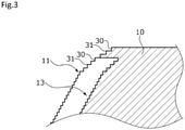
- a plurality of step portions 30 over the entire circumference are formed side by side in the radial direction as illustrated in FIG. 3 and the curved surface-shaped facing surface 11 is configured by connecting corner portions 31 sandwiched between the step portions 30.
- the facing surface 11 has a radial curvature from a macroscopic viewpoint while the minute step portion 30 is formed in the radial direction from a microscopic viewpoint.
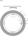
- dynamic pressure generation grooves 13 as a plurality of functional grooves are formed at equal intervals in the circumferential direction and the radial direction on the outer diameter side of the facing surface 11 of the stationary seal ring 10 and fluid introduction grooves 14 as a plurality of functional grooves and positive pressure generation grooves 15 as a plurality of functional grooves are formed at equal intervals in the circumferential direction on the inner diameter side of the facing surface 11.
- the dynamic pressure generation groove 13 is an equiangular spiral, and the part other than the dynamic pressure generation groove 13 on the outer diameter side of the facing surface 11, that is, the part between the dynamic pressure generation grooves 13 is a land 12 forming a curved surface in the radial direction.
- the fluid introduction groove 14 is a groove for introducing a fluid from the inner diameter side and the positive pressure generation groove 15 is a circumferentially extending groove connected to the fluid introduction groove 14.
- the inner diameter side beyond the dynamic pressure generation groove 13 is a land with a large radius of curvature except for the fluid introduction groove 14 and the positive pressure generation groove 15. It should be noted that the number of the dynamic pressure generation grooves 13 can be freely changed in accordance with the environment of use.
- each dynamic pressure generation groove 13 has a bottom surface 13a, which is a curved surface parallel to the surface shape of the land 12 as a curved surface, and the dynamic pressure generation grooves 13 are formed to have the same depth.
- a dynamic pressure is generated in the dynamic pressure generation groove 13 when the stationary seal ring 10 and the rotating seal ring 20 are rotated relative to each other as described later.
- the bottom surface 13a of the dynamic pressure generation groove 13 does not hinder fine recess provision in the flat surface or formation for inclination with respect to the land 12 although the bottom surface 13a of the dynamic pressure generation groove 13 is formed in a curved surface shape parallel to the land 12.
- the dynamic pressure generation groove 13 can be formed by re-performing micromachining by laser on the facing surface 11 laser-machined into a curved surface shape.
- the dynamic pressure generation groove 13 is surrounded by the four surfaces of two surfaces 13b disposed side by side when viewed from the axial direction and forming circular arc-shaped side walls, a wall portion 13c forming the wall at the inner diameter end, that is, the terminal end extending while crossing the circular arc-shaped surfaces 13b, and the bottom surface 13a parallel to the facing surface 11.
- the outer diameter end of the dynamic pressure generation groove 13 is open to the outer diameter side of the dynamic pressure generation groove 13 (see FIG. 4 ).
- the facing surface 21 of the rotating seal ring 20 is formed and disposed so as to be a flat surface orthogonal to the axial direction of the rotary shaft 1 when the rotary shaft 1 is stationary without operation.
- the sealing target liquid F is taken into the dynamic pressure generation groove 13 to result in a state where the facing surface 21 of the rotating seal ring 20 and the facing surface 11 of the stationary seal ring 10 are slightly separated by the positive pressure generated around the wall portion 13c, which is the terminal end of the dynamic pressure generation groove 13.
- the state is the so-called non-contact state of the facing surfaces and leads to friction reduction.
- the rotating seal ring 20 may be deformed due to, for example, the inertial force attributable to the rotation of the rotary shaft 1, the stress attributable to the resistance or load of a component of the general industrial machine such as an impeller rotating with the rotary shaft 1, or a thermal factor attributable to sliding heat generation.
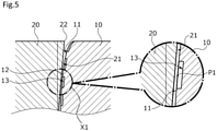
- the rotating seal ring 20 may be deformed so as to tilt in the direction toward the stationary seal ring 10 toward the outer diameter side, which is the free end of the rotating seal ring 20. As illustrated in FIG. 5 , in this case, the outer diameter side of the facing surface 21 of the rotating seal ring 20 becomes close to the outer diameter side of the facing surface 11 of the stationary seal ring 10. It should be noted that the two-dot chain line in FIG. 5 indicates the facing surface 21 of the rotating seal ring 20 during the non-operation.
- the facing surface 11 of the stationary seal ring 10 has a shape in which the part where the facing surface 21 of the rotating seal ring 20 becomes obliquely close is pre-removed in view of the deformation of the rotating seal ring 20 during the rotation. Accordingly, as is clear from FIG. 5 , the facing surface 21 of the rotating seal ring 20 at this time becomes closest to the facing surface 11 of the stationary seal ring 10 in a region X1, which is closer to the inner diameter side than a sharp corner portion 22 at the tip positioned at the outer diameter end, and thus it is possible to prevent damage to the corner portion 22 and the facing surface 11 that the corner portion 22 faces.
- the facing surface 11 of the stationary seal ring 10 has a convex curved surface shape. Accordingly, in a state where the facing surface 11 of the stationary seal ring 10 and the facing surface 21 of the rotating seal ring 20 facing the facing surface 11 of the stationary seal ring 10 are close to each other, a part of the facing surface 11 of the stationary seal ring 10 at an angle close to the inclination angle resulting from the deformation of the facing surface 21 of the rotating seal ring 20 becomes almost parallel to the facing surface 21 of the inclined rotating seal ring 20.
- the facing surface 11 of the stationary seal ring 10 has a curved surface shape around a closest part P1, which is closest to the facing surface 21 of the rotating seal ring 20 on the facing surface 11 of the stationary seal ring 10, and even on both radial sides across the closest part P1, and thus a part of the facing surface 11 of the stationary seal ring 10 becomes almost parallel to the facing surface 21 of the inclined rotating seal ring 20 without being significantly separated from the facing surface 21 of the rotating seal ring 20 and an effective facing region can be secured in the radial direction between the facing surfaces 11 and 21 of the stationary seal ring 10 and the rotating seal ring 20.
- the stationary seal ring 10 and the rotating seal ring 20 are capable of exhibiting stable sealing performance under various conditions.
- the degree of deformation of the rotating seal ring 20 varies depending on external factors. For example, in a case where the inclination of the facing surface 21 of the rotating seal ring 20 is smaller than in FIG. 5 as illustrated in FIG. 6 , a closest part P2 is positioned in a region X2, which is closer to the inner diameter side than the closest part P1 in the state illustrated in FIG. 5 , and a part of the facing surface 11 of the stationary seal ring 10 including the closest part P2 becomes almost parallel to the facing surface 21 of the inclined rotating seal ring 20.
- the facing surface 11 of the stationary seal ring 10 has a convex curved surface shape gradually separated from the rotating seal ring 20 toward the outer diameter end from the inner diameter end, and thus it is possible to secure an effective facing region in the radial direction at all times regardless of the inclination angle of the facing surface 21 attributable to the difference in the degree of deformation of the rotating seal ring 20.
- the present invention can be used for general purposes in, for example, general industrial machines and automobiles of various specifications.
- the facing surface 11 has a curved surface shape from the inner diameter end to the outer diameter end and is capable of finely corresponding to the inclination angle of the facing surface 21 of the rotating seal ring 20.
- the facing surface 11 is provided with a curved surface-shaped part over the circumferential direction, and thus an effective facing region can be secured over the entire circumference in relation to the facing surface 21 of the rotating seal ring 20.
- sealing requires contact between the surfaces or a region close to the extent of being fluid-sealable, that is, a facing region with some width in the radial direction.
- the radius of curvature of the curved surface-shaped facing surface 11 of the stationary seal ring 10 is larger than, for example, the radius of curvature of the facing surface 21 of the rotating seal ring 20 that has a curved surface shape
- the facing surface 11 and the facing surface 21 become closest at either the outermost diameter or the innermost diameter of the seal ring in the radial direction with the curved surface-shaped facing surface 11 of the stationary seal ring 10 and the facing surface 21 of the rotating seal ring 20 facing the curved surface-shaped facing surface 11 of the stationary seal ring 10 close to each other, the facing surface 11 and the facing surface 21 are largely separated from each other on the inner diameter side or the outer diameter side as compared with the closest part, and then it may be impossible to secure an effective facing region and perform sealing appropriately.
- the facing surface 21 of the rotating seal ring 20 in the present embodiment is formed as a flat surface orthogonal to the axial direction of the rotary shaft 1
- the facing surface 11 of the stationary seal ring 10 is formed in a convex curved surface shape gradually separated from the rotating seal ring 20 toward the outer diameter end from the inner diameter end, and thus the closest point does not become the outermost diameter or the innermost diameter of the seal ring, the closest point is disposed on the outer diameter side as compared with the innermost diameter and the inner diameter side as compared with the outermost diameter of the seal ring, and close regions can be secured on both radial sides of the closest point.
- the facing surface 11 of the stationary seal ring 10 is a curved surface formed along the facing surface 21 of the rotating seal ring 20, it is possible to reduce the average inter-surface distance between the facing surfaces 11 and 21 and effectively secure an effective facing region in the radial direction.
- the curved surface shape is formed for the facing surface 11 of the stationary seal ring 10, it is possible to secure an effective facing region with high responsiveness to the degree of deformation of the rotating seal ring 20.
- the dynamic pressure generation groove 13 is formed at the curved surface-shaped part of the facing surface 11 of the stationary seal ring 10, the function of dynamic pressure generation can be effectively exhibited in the effective facing region secured in the radial direction between the stationary seal ring 10 and the rotating seal ring 20.
- the dynamic pressure generation groove 13 has the bottom surface 13a parallel to the surface shape of the land 12 of the facing surface 11, the plurality of dynamic pressure generation grooves 13 are radially formed at the same depth, and thus the function of dynamic pressure generation can be effectively exhibited regardless of the degree of deformation of the rotating seal ring 20.
- the curved surface shape of the facing surface 11 of the stationary seal ring 10 has the minute step portion 30 in the radial direction from a microscopic viewpoint, and thus the sealing target liquid F is held in the step portion 30, a fluid film can be easily formed between the facing surface 11 of the stationary seal ring 10 and the facing surface 21 of the rotating seal ring 20, and high slidability and sealability can be ensured.
- a facing surface 51 of a rotating seal ring 50 is formed into a curved surface shape convex in the facing direction and forms a curved surface portion.
- a facing surface 41 of a stationary seal ring 40 is a flat surface orthogonal to the axial direction.
- the curved surface-shaped facing surface 51 is inclined with respect to the flat facing surface 41 of the stationary seal ring 40 and becomes close to the facing surface 41 in a region X3 around a closest part P3, a part of the facing surface 51 becomes almost parallel to the facing surface 41, and it is possible to secure an effective facing region in the radial direction.
- the facing surface 21 of the rotating seal ring 20 is a flat surface orthogonal to the axial direction of the rotary shaft 1 in the first embodiment, only one point is closest in the radial direction, even if the facing surface 21 of the rotating seal ring 20 has a concave curved surface shape, insofar as the facing surface 21 of the rotating seal ring 20 is larger in radius of curvature than the facing surface 11 of the stationary seal ring 10, and thus it is possible to effectively secure an effective facing region in the radial direction.
- a rotating seal ring having an axially convex curved surface portion as in the second embodiment may face a stationary seal ring having an axially convex curved surface portion as in the first embodiment.
- sliding performance can be ensured regardless of the inclination angle between the facing surfaces of the stationary and rotating seal rings and damage attributable to stress concentration can be prevented.
- the facing surface 11 of the stationary seal ring 10 has a convex curved surface shape gradually separated from the rotating seal ring from the inner diameter end toward the outer diameter end from the outer diameter end to the inner diameter end.
- the present invention is not limited thereto and the facing surface 11 of the stationary seal ring 10 may have a convex curved surface shape gradually separated from the rotating seal ring from the outer diameter end toward the inner diameter end from the outer diameter end to the inner diameter end of the facing surface 11.
- the entire facing surface may constitute the curved surface portion.
- the curved surface portion may be formed so as to extend to the radial middle portion from the outer or inner diameter end of the facing surface 11 and the curved surface portion may not be formed in the entire radial direction.
- the curved surface portion formed on the facing surface 11 may be on both sides in the radial direction while leaving the flat surface radially extending to the middle portion between the outer and inner diameter ends of the facing surface 11 or either the outer diameter end or the inner diameter end of the facing surface 11.
- the groove in the facing surface such as the dynamic pressure generation groove may be formed in the facing surface of the rotating seal ring instead of the facing surface of the stationary seal ring or may be formed in both the facing surface of the stationary seal ring and the facing surface of the rotating seal ring.
- the groove in the facing surface of the stationary seal ring or the facing surface of the rotating seal ring may not be the dynamic pressure generation groove and may be a functional groove having another function such as a Rayleigh step.
- the groove such as the dynamic pressure generation groove may be omitted insofar as the mechanical seal in which the sliding component is used is not in an aspect in which the facing surface of the stationary seal ring and the facing surface of the rotating seal ring are not in contact with each other.
- the sliding component of the present invention is not limited to the inside-type mechanical seal that seals a sealing target fluid to leak from the outer peripheral side of the facing surface toward the inner peripheral side.
- the sliding component of the present invention can be used for an outside-type mechanical seal that seals a sealing target fluid to leak from the inner peripheral side of a facing surface toward the outer peripheral side.
- the sealing target fluid sealed by the sliding component of the present invention may be replaced with a gas.
- the sealing target fluid side is higher in pressure than the atmospheric side
- the fluid pressure relationship between the inner and outer diameter sides of the sliding component is not limited thereto and the pressures may be equal to each other.
- the sliding component of the present invention can be used for a bearing such as a thrust bearing.
Landscapes
- Engineering & Computer Science (AREA)
- General Engineering & Computer Science (AREA)
- Mechanical Engineering (AREA)
- Physics & Mathematics (AREA)
- Fluid Mechanics (AREA)
- Mechanical Sealing (AREA)
- Sliding-Contact Bearings (AREA)
Applications Claiming Priority (2)
| Application Number | Priority Date | Filing Date | Title |
|---|---|---|---|
| JP2019082965 | 2019-04-24 | ||
| PCT/JP2020/017170 WO2020218286A1 (fr) | 2019-04-24 | 2020-04-21 | Élément coulissant |
Publications (2)
| Publication Number | Publication Date |
|---|---|
| EP3961069A1 true EP3961069A1 (fr) | 2022-03-02 |
| EP3961069A4 EP3961069A4 (fr) | 2022-12-14 |
Family
ID=72941967
Family Applications (1)
| Application Number | Title | Priority Date | Filing Date |
|---|---|---|---|
| EP20794826.6A Pending EP3961069A4 (fr) | 2019-04-24 | 2020-04-21 | Élément coulissant |
Country Status (6)
| Country | Link |
|---|---|
| US (1) | US12007027B2 (fr) |
| EP (1) | EP3961069A4 (fr) |
| JP (1) | JP7353726B2 (fr) |
| KR (1) | KR102616659B1 (fr) |
| CN (1) | CN113748285B (fr) |
| WO (1) | WO2020218286A1 (fr) |
Families Citing this family (4)
| Publication number | Priority date | Publication date | Assignee | Title |
|---|---|---|---|---|
| EP4394214A4 (fr) * | 2021-08-25 | 2025-08-06 | Eagle Ind Co Ltd | Composant coulissant |
| CN117859017A (zh) | 2021-08-25 | 2024-04-09 | 伊格尔工业股份有限公司 | 一对滑动部件 |
| WO2023027002A1 (fr) * | 2021-08-25 | 2023-03-02 | イーグル工業株式会社 | Composant coulissant |
| KR20240042051A (ko) | 2021-08-25 | 2024-04-01 | 이구루코교 가부시기가이샤 | 슬라이딩 부품 |
Family Cites Families (83)
| Publication number | Priority date | Publication date | Assignee | Title |
|---|---|---|---|---|
| JPS366305B1 (fr) | 1960-03-31 | 1961-05-30 | ||
| US3085808A (en) | 1960-05-17 | 1963-04-16 | Worthington Corp | Mechanical seal with controlled leakage |
| US3232680A (en) | 1963-08-19 | 1966-02-01 | Whittaker Corp | Fluid bearing |
| US3410565A (en) | 1966-07-27 | 1968-11-12 | Worthington Corp | Centrifugal and face contact seal |
| FR1505487A (fr) | 1966-10-28 | 1967-12-15 | Guinard Pompes | Perfectionnement aux joints tournants à régulation de fuite |
| US3499653A (en) * | 1968-06-05 | 1970-03-10 | Crane Packing Co | Rotary mechanical seal of the gap type |
| US3656227A (en) | 1970-03-26 | 1972-04-18 | Gen Motors Corp | Method of making a mold for bidirectional hydrodynamic shaft seals |
| US3804424A (en) | 1972-04-24 | 1974-04-16 | Crane Packing Co | Gap seal with thermal and pressure distortion compensation |
| DE2222082A1 (de) * | 1972-05-05 | 1973-11-15 | Klein Schanzlin & Becker Ag | Beruehrungsfreie wellendichtung |
| JPS4933614A (fr) | 1972-07-24 | 1974-03-28 | ||
| JPS5271858U (fr) | 1975-11-25 | 1977-05-28 | ||
| US4407512A (en) * | 1976-01-02 | 1983-10-04 | John Crane-Houdaille, Inc. | High pressure rotary mechanical seal |
| JPS5477305A (en) | 1977-12-02 | 1979-06-20 | Hitachi Constr Mach Co Ltd | Compound pump motor |
| JPS58109771A (ja) | 1981-12-23 | 1983-06-30 | Eagle Ind Co Ltd | 非接触型メカニカルシ−ル |
| US4486026A (en) | 1982-02-10 | 1984-12-04 | Nippon Seiko K.K. | Sealing and bearing means by use of ferrofluid |
| JPS58137667A (ja) | 1982-02-10 | 1983-08-16 | Nippon Seiko Kk | 磁性流体シ−ル |
| JPS5958252A (ja) | 1982-09-29 | 1984-04-03 | Honda Motor Co Ltd | Vベルト伝動装置 |
| US4406466A (en) | 1982-11-29 | 1983-09-27 | Elliott Turbomachinery Co., Inc. | Gas lift bearing and oil seal |
| JPS6037463A (ja) * | 1983-08-08 | 1985-02-26 | Nippon Pillar Packing Co Ltd | 非接触式メカニカルシ−ル |
| JPS6037463U (ja) | 1983-08-24 | 1985-03-15 | 本田技研工業株式会社 | 自動車の後部窓ガラス洗浄装置 |
| JPS60107461A (ja) | 1983-11-15 | 1985-06-12 | Jidosha Kiki Co Ltd | 動力舵取装置の制御方法 |
| JPH06100642B2 (ja) | 1984-09-29 | 1994-12-12 | 株式会社東芝 | 光応用磁界センサ |
| GB2179409A (en) * | 1985-08-20 | 1987-03-04 | Angus George Co Ltd | Face seal with pumping action |
| DE3619489A1 (de) | 1986-06-10 | 1987-12-17 | Gutehoffnungshuette Man | Wellendichtung |
| JPS6333027A (ja) | 1986-07-28 | 1988-02-12 | Nippon Hoso Kyokai <Nhk> | 音声デジタル信号伝送方式 |
| CH677266A5 (fr) | 1986-10-28 | 1991-04-30 | Pacific Wietz Gmbh & Co Kg | |
| US4836561A (en) * | 1987-02-17 | 1989-06-06 | University Of New Mexico | Wavy-tilt-dam seal ring |
| US5246295A (en) * | 1991-10-30 | 1993-09-21 | Ide Russell D | Non-contacting mechanical face seal of the gap-type |
| JPH0620155Y2 (ja) | 1987-09-11 | 1994-05-25 | シチズン時計株式会社 | 時計の時刻修正機構 |
| JPH01133572A (ja) | 1987-11-16 | 1989-05-25 | Sanyo Electric Co Ltd | 単相周波数変換回路 |
| JPH06105105B2 (ja) | 1989-03-03 | 1994-12-21 | 日本ピラー工業株式会社 | 端面非接触形メカニカルシール |
| JPH0660691B2 (ja) | 1990-04-17 | 1994-08-10 | イーグル工業株式会社 | 両回転式準接触メカニカルシール及びリング摺動面の溝加工方法 |
| US5492341A (en) | 1990-07-17 | 1996-02-20 | John Crane Inc. | Non-contacting, gap-type seal having a ring with a patterned seal face |
| JPH04145267A (ja) | 1990-10-08 | 1992-05-19 | Ebara Corp | 非接触端面シール |
| GB9103217D0 (en) | 1991-02-15 | 1991-04-03 | Crane John Uk Ltd | Mechanical face seals |
| US5201531A (en) | 1992-04-02 | 1993-04-13 | John Crane Inc. | Face seal with double spiral grooves |
| US5501470A (en) | 1992-12-11 | 1996-03-26 | Nippon Pillar Packing Co., Ltd. | Non-contacting shaft sealing device with grooved face pattern |
| US5441283A (en) | 1993-08-03 | 1995-08-15 | John Crane Inc. | Non-contacting mechanical face seal |
| CA2170746C (fr) | 1993-09-01 | 2005-01-25 | Josef Sedy | Joint a portee plane, avec rainures a angle et annulaires |
| US5498007A (en) | 1994-02-01 | 1996-03-12 | Durametallic Corporation | Double gas barrier seal |
| JP3387236B2 (ja) | 1994-09-22 | 2003-03-17 | 株式会社島津製作所 | 生体磁気計測装置 |
| JPH09329247A (ja) | 1996-06-11 | 1997-12-22 | Ebara Corp | 非接触端面シール |
| JP2999415B2 (ja) | 1996-07-24 | 2000-01-17 | 日本ピラー工業株式会社 | メカニカルシール |
| JPH10281299A (ja) | 1997-04-11 | 1998-10-23 | Mitsubishi Heavy Ind Ltd | メカニカルシール装置 |
| US5895051A (en) | 1997-07-16 | 1999-04-20 | Freudenberg-Nok General Partnership | Noise abating beads on a rack seal |
| PL187630B1 (pl) * | 1998-12-10 | 2004-08-31 | Anga Uszczelnienia Mechaniczne | Pierścień ślizgowy uszczelnienia mechanicznego czołowego bezstykowego |
| US6446976B1 (en) | 2000-09-06 | 2002-09-10 | Flowserve Management Company | Hydrodynamic face seal with grooved sealing dam for zero-leakage |
| CN2460801Y (zh) | 2001-01-18 | 2001-11-21 | 王玉明 | 可双向旋转的螺旋槽端面密封装置 |
| JP4495402B2 (ja) | 2002-03-19 | 2010-07-07 | イーグル工業株式会社 | 摺動部品 |
| US6902168B2 (en) | 2002-03-19 | 2005-06-07 | Eagle Industry Co., Ltd. | Sliding element |
| JP4316956B2 (ja) | 2002-10-23 | 2009-08-19 | イーグル工業株式会社 | 摺動部品 |
| JP4719414B2 (ja) | 2003-12-22 | 2011-07-06 | イーグル工業株式会社 | 摺動部品 |
| JP2005188651A (ja) | 2003-12-25 | 2005-07-14 | Yamada Seisakusho Co Ltd | ウォーターポンプにおけるメカニカルシール |
| JP4322747B2 (ja) | 2004-07-06 | 2009-09-02 | イーグル工業株式会社 | シール装置 |
| US8162322B2 (en) | 2006-10-25 | 2012-04-24 | Rexnord Industries, Llc | Hydrodynamic seal with circumferentially varying lift force |
| US7770895B2 (en) | 2007-05-01 | 2010-08-10 | Eaton Corporation | Segmented seal portion and assembly |
| US8360436B2 (en) | 2008-01-11 | 2013-01-29 | Eagle Industry Co., Ltd. | Mechanical seal sliding member, and mechanical seal |
| JP2009250378A (ja) | 2008-04-08 | 2009-10-29 | Eagle Ind Co Ltd | 液体用のメカニカルシール装置 |
| US8205891B2 (en) | 2008-09-15 | 2012-06-26 | Stein Seal Company | Intershaft seal assembly |
| JP5271858B2 (ja) | 2009-09-29 | 2013-08-21 | アイシン精機株式会社 | メカニカルシール及び液体ポンプ |
| DE102009058315A1 (de) * | 2009-12-15 | 2011-06-16 | Federal-Mogul Burscheid Gmbh | Gleitringdichtung |
| CN101749431B (zh) | 2010-01-28 | 2013-07-31 | 浙江工业大学 | 珍珠链状的圆环槽环带端面机械密封结构 |
| JP5122607B2 (ja) | 2010-06-17 | 2013-01-16 | キヤノンマシナリー株式会社 | 平面摺動機構 |
| JP5693599B2 (ja) | 2010-10-06 | 2015-04-01 | イーグル工業株式会社 | 摺動部品 |
| GB201116121D0 (en) | 2011-09-19 | 2011-11-02 | Rolls Royce Plc | Fluid riding device |
| CN202327105U (zh) * | 2011-11-09 | 2012-07-11 | 四川日机密封件股份有限公司 | 定锥度型波形曲面机械密封装置 |
| CN104334939B (zh) | 2012-08-04 | 2017-05-31 | 伊格尔工业股份有限公司 | 滑动部件 |
| AU2014206300B2 (en) | 2013-01-16 | 2016-10-13 | Eagle Industry Co., Ltd. | Sliding part |
| WO2014148316A1 (fr) | 2013-03-17 | 2014-09-25 | イーグル工業株式会社 | Élément coulissant |
| US9587745B2 (en) | 2013-04-24 | 2017-03-07 | Eagle Industry Co., Ltd. | Sliding component |
| CN103307284B (zh) * | 2013-07-10 | 2015-10-21 | 南京林业大学 | 具有自紧密封能力的剖分式机械密封 |
| JP6037463B2 (ja) | 2014-05-26 | 2016-12-07 | 富士フイルム株式会社 | インクジェット記録装置及びイジェクタの異常検出方法 |
| JP6479023B2 (ja) | 2014-09-04 | 2019-03-06 | イーグル工業株式会社 | メカニカルシール |
| JP6224568B2 (ja) | 2014-10-17 | 2017-11-01 | イーグル工業株式会社 | メカニカルシール |
| JP6444492B2 (ja) | 2015-04-15 | 2018-12-26 | イーグル工業株式会社 | 摺動部品 |
| JP6678169B2 (ja) * | 2015-05-19 | 2020-04-08 | イーグル工業株式会社 | 摺動部品 |
| AU2016286896A1 (en) | 2015-06-30 | 2018-01-18 | Eagle Industry Co., Ltd. | Seal device |
| CN109563934A (zh) | 2016-08-15 | 2019-04-02 | 伊格尔工业股份有限公司 | 滑动部件 |
| JP6861730B2 (ja) | 2016-12-07 | 2021-04-21 | イーグル工業株式会社 | しゅう動部品 |
| US11125334B2 (en) * | 2016-12-21 | 2021-09-21 | Eaton Intelligent Power Limited | Hydrodynamic sealing component and assembly |
| GB201702893D0 (en) * | 2017-02-23 | 2017-04-12 | Aes Eng Ltd | Mechanical seal |
| TWI640704B (zh) * | 2017-06-06 | 2018-11-11 | 祥景精機股份有限公司 | 具有反曲點溝槽之非接觸式氣體軸封 |
| CN208719352U (zh) * | 2018-07-23 | 2019-04-09 | 浙江工业大学 | 开放椭圆型线槽端面双向旋转机械密封结构 |
-
2020
- 2020-04-21 KR KR1020217036306A patent/KR102616659B1/ko active Active
- 2020-04-21 WO PCT/JP2020/017170 patent/WO2020218286A1/fr not_active Ceased
- 2020-04-21 CN CN202080029042.1A patent/CN113748285B/zh active Active
- 2020-04-21 JP JP2021516130A patent/JP7353726B2/ja active Active
- 2020-04-21 EP EP20794826.6A patent/EP3961069A4/fr active Pending
- 2020-04-21 US US17/603,561 patent/US12007027B2/en active Active
Also Published As
| Publication number | Publication date |
|---|---|
| KR20210148329A (ko) | 2021-12-07 |
| CN113748285B (zh) | 2024-12-24 |
| JP7353726B2 (ja) | 2023-10-02 |
| CN113748285A (zh) | 2021-12-03 |
| EP3961069A4 (fr) | 2022-12-14 |
| KR102616659B1 (ko) | 2023-12-21 |
| JPWO2020218286A1 (fr) | 2020-10-29 |
| US20220196152A1 (en) | 2022-06-23 |
| WO2020218286A1 (fr) | 2020-10-29 |
| US12007027B2 (en) | 2024-06-11 |
Similar Documents
| Publication | Publication Date | Title |
|---|---|---|
| JP7179430B2 (ja) | 摺動部品 | |
| US12007027B2 (en) | Sliding component | |
| EP3748205B1 (fr) | Pièces coulissantes | |
| JP6861730B2 (ja) | しゅう動部品 | |
| CN113412369B (zh) | 滑动部件 | |
| JP6138132B2 (ja) | 摺動部品 | |
| US12510113B2 (en) | Sliding component | |
| JPWO2020171102A1 (ja) | 摺動部品 | |
| EP3926186B1 (fr) | Élément coulissant | |
| US12473946B2 (en) | Sliding components | |
| EP4332415A1 (fr) | Élément coulissant | |
| JP2010084802A (ja) | ロータリーシール | |
| JP2004332920A (ja) | 密封構造及び端面シール | |
| JP7350447B2 (ja) | メカニカルシール | |
| KR20250111189A (ko) | 슬라이딩 부품 | |
| TW202605255A (zh) | 滑動部件 | |
| WO2025239228A1 (fr) | Composant coulissant |
Legal Events
| Date | Code | Title | Description |
|---|---|---|---|
| STAA | Information on the status of an ep patent application or granted ep patent |
Free format text: STATUS: THE INTERNATIONAL PUBLICATION HAS BEEN MADE |
|
| PUAI | Public reference made under article 153(3) epc to a published international application that has entered the european phase |
Free format text: ORIGINAL CODE: 0009012 |
|
| STAA | Information on the status of an ep patent application or granted ep patent |
Free format text: STATUS: REQUEST FOR EXAMINATION WAS MADE |
|
| 17P | Request for examination filed |
Effective date: 20211025 |
|
| AK | Designated contracting states |
Kind code of ref document: A1 Designated state(s): AL AT BE BG CH CY CZ DE DK EE ES FI FR GB GR HR HU IE IS IT LI LT LU LV MC MK MT NL NO PL PT RO RS SE SI SK SM TR |
|
| DAV | Request for validation of the european patent (deleted) | ||
| DAX | Request for extension of the european patent (deleted) | ||
| A4 | Supplementary search report drawn up and despatched |
Effective date: 20221114 |
|
| RIC1 | Information provided on ipc code assigned before grant |
Ipc: F16C 33/74 20060101ALI20221108BHEP Ipc: F16J 15/34 20060101AFI20221108BHEP |
|
| STAA | Information on the status of an ep patent application or granted ep patent |
Free format text: STATUS: EXAMINATION IS IN PROGRESS |
|
| 17Q | First examination report despatched |
Effective date: 20230719 |