EP3926060A1 - Feuille d'acier électromagnétique non orientée - Google Patents
Feuille d'acier électromagnétique non orientée Download PDFInfo
- Publication number
- EP3926060A1 EP3926060A1 EP20756077.2A EP20756077A EP3926060A1 EP 3926060 A1 EP3926060 A1 EP 3926060A1 EP 20756077 A EP20756077 A EP 20756077A EP 3926060 A1 EP3926060 A1 EP 3926060A1
- Authority
- EP
- European Patent Office
- Prior art keywords
- mass
- less
- steel sheet
- annealing
- electrical steel
- Prior art date
- Legal status (The legal status is an assumption and is not a legal conclusion. Google has not performed a legal analysis and makes no representation as to the accuracy of the status listed.)
- Pending
Links
Images
Classifications
-
- C—CHEMISTRY; METALLURGY
- C21—METALLURGY OF IRON
- C21D—MODIFYING THE PHYSICAL STRUCTURE OF FERROUS METALS; GENERAL DEVICES FOR HEAT TREATMENT OF FERROUS OR NON-FERROUS METALS OR ALLOYS; MAKING METAL MALLEABLE, e.g. BY DECARBURISATION OR TEMPERING
- C21D8/00—Modifying the physical properties by deformation combined with, or followed by, heat treatment
- C21D8/12—Modifying the physical properties by deformation combined with, or followed by, heat treatment during manufacturing of articles with special electromagnetic properties
- C21D8/1244—Modifying the physical properties by deformation combined with, or followed by, heat treatment during manufacturing of articles with special electromagnetic properties the heat treatment(s) being of interest
- C21D8/1272—Final recrystallisation annealing
-
- C—CHEMISTRY; METALLURGY
- C21—METALLURGY OF IRON
- C21D—MODIFYING THE PHYSICAL STRUCTURE OF FERROUS METALS; GENERAL DEVICES FOR HEAT TREATMENT OF FERROUS OR NON-FERROUS METALS OR ALLOYS; MAKING METAL MALLEABLE, e.g. BY DECARBURISATION OR TEMPERING
- C21D1/00—General methods or devices for heat treatment, e.g. annealing, hardening, quenching or tempering
- C21D1/02—Hardening articles or materials formed by forging or rolling, with no further heating beyond that required for the formation
-
- C—CHEMISTRY; METALLURGY
- C21—METALLURGY OF IRON
- C21D—MODIFYING THE PHYSICAL STRUCTURE OF FERROUS METALS; GENERAL DEVICES FOR HEAT TREATMENT OF FERROUS OR NON-FERROUS METALS OR ALLOYS; MAKING METAL MALLEABLE, e.g. BY DECARBURISATION OR TEMPERING
- C21D6/00—Heat treatment of ferrous alloys
- C21D6/008—Heat treatment of ferrous alloys containing Si
-
- C—CHEMISTRY; METALLURGY
- C21—METALLURGY OF IRON
- C21D—MODIFYING THE PHYSICAL STRUCTURE OF FERROUS METALS; GENERAL DEVICES FOR HEAT TREATMENT OF FERROUS OR NON-FERROUS METALS OR ALLOYS; MAKING METAL MALLEABLE, e.g. BY DECARBURISATION OR TEMPERING
- C21D8/00—Modifying the physical properties by deformation combined with, or followed by, heat treatment
- C21D8/12—Modifying the physical properties by deformation combined with, or followed by, heat treatment during manufacturing of articles with special electromagnetic properties
- C21D8/1205—Modifying the physical properties by deformation combined with, or followed by, heat treatment during manufacturing of articles with special electromagnetic properties involving a particular fabrication or treatment of ingot or slab
- C21D8/1211—Rapid solidification; Thin strip casting
-
- C—CHEMISTRY; METALLURGY
- C21—METALLURGY OF IRON
- C21D—MODIFYING THE PHYSICAL STRUCTURE OF FERROUS METALS; GENERAL DEVICES FOR HEAT TREATMENT OF FERROUS OR NON-FERROUS METALS OR ALLOYS; MAKING METAL MALLEABLE, e.g. BY DECARBURISATION OR TEMPERING
- C21D8/00—Modifying the physical properties by deformation combined with, or followed by, heat treatment
- C21D8/12—Modifying the physical properties by deformation combined with, or followed by, heat treatment during manufacturing of articles with special electromagnetic properties
- C21D8/1216—Modifying the physical properties by deformation combined with, or followed by, heat treatment during manufacturing of articles with special electromagnetic properties the working step(s) being of interest
- C21D8/1222—Hot rolling
-
- C—CHEMISTRY; METALLURGY
- C21—METALLURGY OF IRON
- C21D—MODIFYING THE PHYSICAL STRUCTURE OF FERROUS METALS; GENERAL DEVICES FOR HEAT TREATMENT OF FERROUS OR NON-FERROUS METALS OR ALLOYS; MAKING METAL MALLEABLE, e.g. BY DECARBURISATION OR TEMPERING
- C21D8/00—Modifying the physical properties by deformation combined with, or followed by, heat treatment
- C21D8/12—Modifying the physical properties by deformation combined with, or followed by, heat treatment during manufacturing of articles with special electromagnetic properties
- C21D8/1216—Modifying the physical properties by deformation combined with, or followed by, heat treatment during manufacturing of articles with special electromagnetic properties the working step(s) being of interest
- C21D8/1227—Warm rolling
-
- C—CHEMISTRY; METALLURGY
- C21—METALLURGY OF IRON
- C21D—MODIFYING THE PHYSICAL STRUCTURE OF FERROUS METALS; GENERAL DEVICES FOR HEAT TREATMENT OF FERROUS OR NON-FERROUS METALS OR ALLOYS; MAKING METAL MALLEABLE, e.g. BY DECARBURISATION OR TEMPERING
- C21D8/00—Modifying the physical properties by deformation combined with, or followed by, heat treatment
- C21D8/12—Modifying the physical properties by deformation combined with, or followed by, heat treatment during manufacturing of articles with special electromagnetic properties
- C21D8/1216—Modifying the physical properties by deformation combined with, or followed by, heat treatment during manufacturing of articles with special electromagnetic properties the working step(s) being of interest
- C21D8/1233—Cold rolling
-
- C—CHEMISTRY; METALLURGY
- C21—METALLURGY OF IRON
- C21D—MODIFYING THE PHYSICAL STRUCTURE OF FERROUS METALS; GENERAL DEVICES FOR HEAT TREATMENT OF FERROUS OR NON-FERROUS METALS OR ALLOYS; MAKING METAL MALLEABLE, e.g. BY DECARBURISATION OR TEMPERING
- C21D8/00—Modifying the physical properties by deformation combined with, or followed by, heat treatment
- C21D8/12—Modifying the physical properties by deformation combined with, or followed by, heat treatment during manufacturing of articles with special electromagnetic properties
- C21D8/1244—Modifying the physical properties by deformation combined with, or followed by, heat treatment during manufacturing of articles with special electromagnetic properties the heat treatment(s) being of interest
- C21D8/1261—Modifying the physical properties by deformation combined with, or followed by, heat treatment during manufacturing of articles with special electromagnetic properties the heat treatment(s) being of interest following hot rolling
-
- C—CHEMISTRY; METALLURGY
- C21—METALLURGY OF IRON
- C21D—MODIFYING THE PHYSICAL STRUCTURE OF FERROUS METALS; GENERAL DEVICES FOR HEAT TREATMENT OF FERROUS OR NON-FERROUS METALS OR ALLOYS; MAKING METAL MALLEABLE, e.g. BY DECARBURISATION OR TEMPERING
- C21D9/00—Heat treatment, e.g. annealing, hardening, quenching or tempering, adapted for particular articles; Furnaces therefor
- C21D9/46—Heat treatment, e.g. annealing, hardening, quenching or tempering, adapted for particular articles; Furnaces therefor for sheet metals
-
- C—CHEMISTRY; METALLURGY
- C22—METALLURGY; FERROUS OR NON-FERROUS ALLOYS; TREATMENT OF ALLOYS OR NON-FERROUS METALS
- C22C—ALLOYS
- C22C38/00—Ferrous alloys, e.g. steel alloys
- C22C38/002—Ferrous alloys, e.g. steel alloys containing In, Mg, or other elements not provided for in one single group C22C38/001 - C22C38/60
-
- C—CHEMISTRY; METALLURGY
- C22—METALLURGY; FERROUS OR NON-FERROUS ALLOYS; TREATMENT OF ALLOYS OR NON-FERROUS METALS
- C22C—ALLOYS
- C22C38/00—Ferrous alloys, e.g. steel alloys
- C22C38/004—Very low carbon steels, i.e. having a carbon content of less than 0,01%
-
- C—CHEMISTRY; METALLURGY
- C22—METALLURGY; FERROUS OR NON-FERROUS ALLOYS; TREATMENT OF ALLOYS OR NON-FERROUS METALS
- C22C—ALLOYS
- C22C38/00—Ferrous alloys, e.g. steel alloys
- C22C38/005—Ferrous alloys, e.g. steel alloys containing rare earths, i.e. Sc, Y, Lanthanides
-
- C—CHEMISTRY; METALLURGY
- C22—METALLURGY; FERROUS OR NON-FERROUS ALLOYS; TREATMENT OF ALLOYS OR NON-FERROUS METALS
- C22C—ALLOYS
- C22C38/00—Ferrous alloys, e.g. steel alloys
- C22C38/008—Ferrous alloys, e.g. steel alloys containing tin
-
- C—CHEMISTRY; METALLURGY
- C22—METALLURGY; FERROUS OR NON-FERROUS ALLOYS; TREATMENT OF ALLOYS OR NON-FERROUS METALS
- C22C—ALLOYS
- C22C38/00—Ferrous alloys, e.g. steel alloys
- C22C38/02—Ferrous alloys, e.g. steel alloys containing silicon
-
- C—CHEMISTRY; METALLURGY
- C22—METALLURGY; FERROUS OR NON-FERROUS ALLOYS; TREATMENT OF ALLOYS OR NON-FERROUS METALS
- C22C—ALLOYS
- C22C38/00—Ferrous alloys, e.g. steel alloys
- C22C38/04—Ferrous alloys, e.g. steel alloys containing manganese
-
- C—CHEMISTRY; METALLURGY
- C22—METALLURGY; FERROUS OR NON-FERROUS ALLOYS; TREATMENT OF ALLOYS OR NON-FERROUS METALS
- C22C—ALLOYS
- C22C38/00—Ferrous alloys, e.g. steel alloys
- C22C38/06—Ferrous alloys, e.g. steel alloys containing aluminium
-
- C—CHEMISTRY; METALLURGY
- C22—METALLURGY; FERROUS OR NON-FERROUS ALLOYS; TREATMENT OF ALLOYS OR NON-FERROUS METALS
- C22C—ALLOYS
- C22C38/00—Ferrous alloys, e.g. steel alloys
- C22C38/16—Ferrous alloys, e.g. steel alloys containing copper
-
- C—CHEMISTRY; METALLURGY
- C22—METALLURGY; FERROUS OR NON-FERROUS ALLOYS; TREATMENT OF ALLOYS OR NON-FERROUS METALS
- C22C—ALLOYS
- C22C38/00—Ferrous alloys, e.g. steel alloys
- C22C38/18—Ferrous alloys, e.g. steel alloys containing chromium
-
- H—ELECTRICITY
- H01—ELECTRIC ELEMENTS
- H01F—MAGNETS; INDUCTANCES; TRANSFORMERS; SELECTION OF MATERIALS FOR THEIR MAGNETIC PROPERTIES
- H01F1/00—Magnets or magnetic bodies characterised by the magnetic materials therefor; Selection of materials for their magnetic properties
- H01F1/01—Magnets or magnetic bodies characterised by the magnetic materials therefor; Selection of materials for their magnetic properties of inorganic materials
- H01F1/03—Magnets or magnetic bodies characterised by the magnetic materials therefor; Selection of materials for their magnetic properties of inorganic materials characterised by their coercivity
- H01F1/12—Magnets or magnetic bodies characterised by the magnetic materials therefor; Selection of materials for their magnetic properties of inorganic materials characterised by their coercivity of soft-magnetic materials
- H01F1/14—Magnets or magnetic bodies characterised by the magnetic materials therefor; Selection of materials for their magnetic properties of inorganic materials characterised by their coercivity of soft-magnetic materials metals or alloys
- H01F1/147—Alloys characterised by their composition
-
- C—CHEMISTRY; METALLURGY
- C21—METALLURGY OF IRON
- C21D—MODIFYING THE PHYSICAL STRUCTURE OF FERROUS METALS; GENERAL DEVICES FOR HEAT TREATMENT OF FERROUS OR NON-FERROUS METALS OR ALLOYS; MAKING METAL MALLEABLE, e.g. BY DECARBURISATION OR TEMPERING
- C21D2201/00—Treatment for obtaining particular effects
- C21D2201/05—Grain orientation
-
- H—ELECTRICITY
- H01—ELECTRIC ELEMENTS
- H01F—MAGNETS; INDUCTANCES; TRANSFORMERS; SELECTION OF MATERIALS FOR THEIR MAGNETIC PROPERTIES
- H01F1/00—Magnets or magnetic bodies characterised by the magnetic materials therefor; Selection of materials for their magnetic properties
- H01F1/01—Magnets or magnetic bodies characterised by the magnetic materials therefor; Selection of materials for their magnetic properties of inorganic materials
- H01F1/03—Magnets or magnetic bodies characterised by the magnetic materials therefor; Selection of materials for their magnetic properties of inorganic materials characterised by their coercivity
- H01F1/12—Magnets or magnetic bodies characterised by the magnetic materials therefor; Selection of materials for their magnetic properties of inorganic materials characterised by their coercivity of soft-magnetic materials
- H01F1/14—Magnets or magnetic bodies characterised by the magnetic materials therefor; Selection of materials for their magnetic properties of inorganic materials characterised by their coercivity of soft-magnetic materials metals or alloys
- H01F1/147—Alloys characterised by their composition
- H01F1/14766—Fe-Si based alloys
- H01F1/14775—Fe-Si based alloys in the form of sheets
Definitions
- the present disclosure relates to electrical steel sheet suitably used for applications such as magnetic cores of electric motors.
- Non-oriented electrical steel sheet is used as a material for iron cores in motors, generators, and other rotating equipment or small sized transformers or other stationary equipment and plays an important role in determining the energy efficiency of electrical equipment.
- core loss and magnetic flux density are mentioned.
- non-oriented electrical steel sheet low in core loss and high in magnetic flux density and a method for manufacturing the same is being sought.
- non-oriented electrical steel sheet for example, if using blanks for use as stator cores for motors cut out from non-oriented electrical steel sheet, spaces are formed at the center parts of the blanks. If using the parts cut out for forming the spaces at the center parts as blanks for rotor use, that is, if fabricating a blank for rotor use and a blank for stator core use from a single non-oriented electrical steel sheet, the yield rises, so this is preferable.
- non-oriented electrical steel sheet made higher in strength by making the crystal grain size finer and leaving behind working strain is demanded.
- high strength is not required for stator cores.
- Excellent magnetic properties obtained by making the crystal grain size coarser and relieving the working strain are demanded. For this reason, if fabricating a blank for rotor use and a blank for stator core use from a single non-oriented electrical steel sheet, after the blank cut out for stator use is shaped into a stator core, additional heat treatment is performed to relieve the strain due to working the non-oriented electrical steel sheet made higher in strength and make the crystal grains coarser to raise the magnetic properties for use. This heat treatment is known as "stress relief annealing".
- high speed motors In high speed motors, the centrifugal force acting on a rotary body such as a rotor becomes larger. Therefore, high strength is sought from the electrical steel sheet used as a material for rotors of high speed motors.
- the average grain size is relatively large, so sufficient tensile strength cannot be obtained.
- the present disclosure was made in consideration of the above-mentioned technical problem and has as its main object the provision of non-oriented electrical steel sheet used for example in drive motors etc. used for automobiles wherein it is made possible to fabricate a blank for rotor use having sufficient strength and a blank for stator core use having excellent magnetic properties (high magnetic flux density and low core loss) from a single non-oriented electrical steel sheet.
- electrical steel sheet with a random intensity ratio of the ⁇ 100 ⁇ orientations of the 1/2 center layer (below, sometimes referred to as the " ⁇ 100 ⁇ intensity") of a predetermined value or more and with ratios of composition of the Si, Al, and Mn in the electrical steel sheet in predetermined ranges can obtain the effect of reduction of the core loss due to stress relief annealing when performing such stress relief annealing and, by the total effect of the effect of improvement of the magnetic flux density due to making the ⁇ 100 ⁇ intensity higher and the effect of reduction of the core loss, the effect of improvement of the magnetic flux density while greatly reducing the core loss and thereby completed the present invention.
- preferably diameter 100 nm or less metal Cu particles are contained in 5/10 ⁇ m 3 or more.
- the tensile strength is 600 MPa or more.
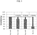
- FIG. 1 is a graph showing the amount of drop of core loss in the examples.
- the non-oriented electrical steel sheet of the present disclosure is extremely high in effect of reduction of the core loss at the time of stress relief annealing, so can give final finished products having high magnetic properties. This is believed to be due to the following reasons.
- the non-oriented electrical steel sheet of the present disclosure has a parameter Q made 2 or more so as to make the steel sheet a single ⁇ -Fe phase and has a ⁇ 100 ⁇ intensity made 2.4 or more to thereby make the crystal orientations at the time of manufacture of the electrical steel sheet (that is, after finish annealing and before stress relief annealing) advantageous for lowering the core loss.
- a parameter Q made 2 or more so as to make the steel sheet a single ⁇ -Fe phase and has a ⁇ 100 ⁇ intensity made 2.4 or more to thereby make the crystal orientations at the time of manufacture of the electrical steel sheet (that is, after finish annealing and before stress relief annealing) advantageous for lowering the core loss.
- the selectively of orientation is changed when deliberately lowering the annealing temperature at the initial stage of recrystallization (stage of 30 ⁇ m or less as crystal grain size) to keep down the crystal grain size and promoting growth of the crystals formed by a relatively high heating rate by a relatively low heating rate at the stage of grain growth in the latter period of recrystallization (stage of over 30 ⁇ m as crystal grain size).
- the chemical composition of the non-oriented electrical steel sheet of the present disclosure will be explained.
- the chemical composition explained below is the composition of the steel constituents forming the steel sheet. If the steel sheet used as the measurement sample has an insulating film etc. on its surface, it is the value after removing the same.
- the content of C is 0.0030 mass% or less.
- the content of C is large, it enlarges the austenite region and increases the phase transformation sections to suppress crystal grain growth of ferrite at the time of annealing, so is liable to cause an increase in the core loss. Further, if magnetic aging occurs, the magnetic properties in a high magnetic field also end up deteriorating, so the content of C is preferably made low.
- the degassing facility at the molten steel stage for example, RH vacuum degassing facility
- the content of C is preferably small.
- the content of C is preferably 0.0015 mass% or less, more preferably 0.0012 mass% or less.
- the content of Si is 2.0 mass% or more and 4.0 mass% or less.
- Si is an important element added for obtaining the action of increasing the specific resistance to lower the eddy current loss. If the content of Si is small, the action of lowering the eddy current loss becomes hard to obtain, while if it is large, the steel sheet is liable to break at the time of cold rolling.
- the content of Al is 0.010 mass% or more and 3.0 mass% or less.
- Al is an element unavoidably added to deoxidize the steel in the steelmaking process and, like Si, is a main element added for obtaining the action of increasing the specific resistance to lower the eddy current loss. For this reason, Al is added in a large amount to lower the core loss, but if a large amount is added, the saturated magnetic flux density is reduced. In the present disclosure, it is needed so that the later explained parameter Q has to be made 2 or more and the structure made a single ⁇ -Fe phase.
- the content of Mn is 0.10 mass% or more and 2.4 mass% or less.
- Mn may be proactively added for raising the strength of steel, but in the present disclosure, which makes positive use of Cu particulates as the main means for achieving high strength, it is not particularly required for that purpose. It is added for the purpose of raising the intrinsic resistance or making the sulfides coarser and promoting crystal grain growth so as to decrease the core loss, but excessive addition lowers the magnetic flux density.
- the content of P is 0.0050 mass% or more and 0.20 mass% or less.
- P is an element with a remarkable effect of raising the tensile strength, but like Mn does not have to be deliberately added for this purpose in the present disclosure.
- P is added since it increases the specific resistance to lower the core loss and segregates at the crystal grain boundaries to thereby suppress formation of the ⁇ 111 ⁇ crystal texture disadvantageous to the magnetic properties and promote the formation of a ⁇ 100 ⁇ crystal texture advantageous to the magnetic properties.
- excessive addition causes the steel to become brittle and lowers the cold reliability and workability of the product.
- the content of S is 0.0030 mass% or less.
- MnS finely precipitates in the process of steel manufacture (>100 ⁇ m) and might suppress grain growth at the time of stress relief annealing. For this reason, the sulfides formed may cause deterioration of the magnetic properties, in particular the core loss, so the content of S is preferably as low as possible. Preferably, it is 0.0020 mass or less, more preferably 0.0010 mass or less.
- the total is 0.00050 mass% or more.
- At least one type of composition selected from the group comprising Sn: 0.02 mass% or more and 0.40 mass% or less, Cr: 0.02 mass% or more and 2.00 mass% or less, and Cu: 0.10 mass% or more and 2.00 mass% or less.
- Sn, Cr, and Cu cause the formation of crystals optimal for improving the magnetic properties by primary recrystallization.
- Sn, Cr, or Cu is included, a crystal texture formed with ⁇ 100 ⁇ crystals suitable for uniform improvement of the magnetic properties in all directions in the sheet plane is easily obtained by primary recrystallization.
- Sn, Cr, and Cu suppress oxidation and nitridation of the surface of steel sheet at the time of finish annealing and suppress variations in size of the crystal grains. Therefore, Sn, Cr, or Cu may be included.
- the balance is Fe and unavoidable impurities.
- unavoidable impurities Nb, Zr, Mo, V, etc. are elements forming carbonitrides, so are preferably reduced as much as possible.
- the contents of these are preferably respectively 0.01 mass or less.
- the parameter Q shown by the following formula (1) is 2.0 or more.
- Q Si + 2 A 1 ⁇ Mn
- the ⁇ 100 ⁇ intensity used is 2.4 or more. In this as well, 3.0 or more, in particular 3.5 or more, is preferable. Note that, no upper limit is particularly set, but it may be made 30 or less.
- the ⁇ 100 ⁇ intensity that is, the X-ray random intensity ratio of the ⁇ -Fe phases of ⁇ 100 ⁇ , can be found from a reverse pole diagram obtained by measurement and calculation by X-ray diffraction.
- the "random intensity ratio" is the value obtained by measuring the X-ray intensities of a standard sample not having integration to any specific orientation and a test sample under the same conditions and dividing the obtained X-ray intensity of the test sample by the X-ray intensity of the standard sample.
- the measurement is performed at the position of a thickness 1/2 layer of the sample. At this time, the measurement surface is finished by chemical polishing etc. so as to become smooth.
- the crystal grain size is 30 ⁇ m or less, preferably 25 ⁇ m or less, more preferably 15 ⁇ m or less. Further, the lower limit value is preferably 3 ⁇ m or more, particularly preferably 15 ⁇ m or more. If the crystal grain size is larger than the above range, the improvement in the value of the core loss due to stress relief annealing is small and as a result the magnetic properties of the member after stress relief annealing end up deteriorating. On the other hand, if smaller than the above range, the value of the core loss of a member not treated by stress relief annealing ends up becoming larger.
- the tensile strength falls and the desired tensile strength cannot be obtained.
- the tensile strength is raised to 600 MPa or more and higher strength is achieved.
- the reason why the tensile strength rises if the crystal grains are fine is believed to be as follows: The tensile strength rises if dislocations in the steel material (defect in lattice) become harder to move. Further, it is known that if the dislocations reach the grain boundaries, they become harder to move. That is, if there are many grain boundaries, in other words, if the crystal grains are made finer, the tensile strength rises.
- the above crystal grain size is the average grain size and can be obtained by the following method of measurement.
- a sample having a cross-section parallel to the rolling surface of the non-oriented electrical steel sheet is prepared by polishing etc.
- the polished surface of this sample (below, referred to as the "observed surface") is electrolytically polished to prepare the surface, then is analyzed for crystal structure utilizing the electron backscatter diffraction method (EBSD).
- EBSD electron backscatter diffraction method
- a grain size means a circle equivalent diameter.
- diameter 100 nm or less metal Cu particles may also be included in amounts of 5 particles/10 ⁇ m 2 or more.
- the presence of the metal Cu particles is believed to raise the strength of the non-oriented electrical steel sheet of the present disclosure and to contribute to improvement of the magnetic properties at the time of stress relief annealing as well.
- the diameter of the metal Cu particles is 100 nm or less. In particular, 1 nm to 20 nm in range, especially 3 nm to 10 nm in range, is preferable. Particles larger than the above range cause the efficiency of increasing strength to remarkably fall and make a large amount of Cu required, so the detrimental effect on the magnetic properties becomes greater. On the other hand, if the particles are smaller than the above range, the detrimental effect on the magnetic properties becomes greater, so this is not preferable.
- the diameter of the metal Cu particles can be determined by observation by an electron microscope. Note that, the "diameter" of the metal Cu particles also means the circle equivalent diameter.
- the number density of the metal Cu particles is 5/10 ⁇ m 2 or more.
- the number density of metal Cu particles is found by using the same sample, measuring oxides in a 10 ⁇ m ⁇ 10 ⁇ m field, and taking the average of the measured values of at least five fields or more.
- the sheet is held in the 450°C to 720°C temperature region for 30 seconds or more. Furthermore, in the later processes, it is preferable to not hold the sheet in the temperature region over 800°C for 20 seconds or more.
- this heat treatment process After this heat treatment process, the steel material becomes higher in strength, so this heat treatment process is performed after the rolling process. Performing it simultaneously with recrystallization annealing and other heat treatment considered necessary for other purposes is advantageous from the viewpoint of productivity. That is, if cold rolled electrical steel sheet, it is preferable to hold it at a 450°C to 720°C temperature region for 30 seconds or more in the final heat treatment process after cold rolling while if hot rolled electrical steel sheet, it is preferable to hold it there for that long in the process of cooling from the 750°C or more temperature region in the final heat treatment process after hot rolling.
- the present disclosure does not utilize strengthening by refining the crystal structure, so there is the effect that even if performing SRA (stress relief annealing) to restore strain introduced in the material when stamping steel sheet and working it into a motor part and to grow the crystal grains to restore and improve the magnetism, the deterioration in strength is small.
- SRA stress relief annealing
- the non-oriented electrical steel sheet of the present disclosure may further have an insulating film on the surface of the steel sheet.
- the insulating film in the present disclosure is not particularly limited. It can be suitably selected and used in accordance with the application etc. from among known ones. It may be either an organic-based film or an inorganic-based film.
- the organic-based film for example, a polyamine-based resin, acrylic resin, acrylstyrene resin, alkyd resin, polyester resin, silicone resin, fluororesin, polyolefin resin, styrene resin, vinyl acetate resin, epoxy resin, phenol resin, urethane resin, melamine resin, etc. may be mentioned.
- the inorganic-based film for example, a phosphate-based film or aluminum phosphate-based film or further an organic-inorganic composite film including the above resin etc. may be mentioned.
- the thickness of the insulating film is not particularly limited, but a thickness per side of 0.05 ⁇ m or more and 2 ⁇ m or less is preferable.
- the method of forming the insulating film is not particularly limited, but for example the above resin or inorganic substance may be dissolved in a solvent to prepare a composition for forming the insulating film and that composition for forming the insulating film may be uniformly coated on the surface of the steel sheet by a known method to form the insulating film.
- the thickness of the electrical steel sheet of the present disclosure is not particularly limited so long as being suitably adjusted in accordance with the application etc., but from the viewpoint of manufacture, it is usually 0.10 mm or more and 0.60 mm or less, more preferably 0.015 mm or more and 0.50 mm or less. From the viewpoint of the balance of the magnetic properties and productivity, 0.015 mm or more and 0.35 mm or less is preferable.
- the electrical steel sheet of the present disclosure is particularly suited for applications where it is used stamped into a desired shape.
- it can be suitably used for servo motors used for electrical equipment, stepping motors, compressors of electrical equipment, motors used for industrial applications, drive motors for electric vehicles, hybrid vehicles, and trains, generators and cores used for various applications, choke coils, reactors, current sensors, and other conventionally known applications where electrical steel sheets are used.
- the method for manufacturing the above-mentioned non-oriented electrical steel sheet of the present disclosure is not particularly limited, but the following (1) high temperature hot rolling sheet annealing+cold rolling strong reduction method, (2) thin slab continuous casting method, (3) lubricating hot rolling method, (4) strip casting method, etc. may be mentioned.
- the chemical composition of the slab or other starting material is the chemical composition described in the above section "A. Non-oriented electrical steel sheet, 1. Chemical composition”.
- a slab is manufactured by a steelmaking process.
- the slab is heated by a reheating furnace, then rough rolled and finish rolled consecutively in a hot rolling process to obtain a hot rolled coil.
- the hot rolling conditions are not particularly limited. It may be a general method of manufacture, that is, a method of manufacture completing the finish hot rolling of a slab heated to 1000 to 1200°C at 700 to 900°C and coiling it at 500 to 700°C.
- the hot rolled coil of steel sheet is hot rolling sheet annealed. Due to the hot rolling sheet annealing, the steel sheet is made to recrystallize and the crystal grains are made to grow coarsely to a crystal grain size of 300 to 500 ⁇ m.
- the hot rolling sheet annealing may be continuous annealing or may be batch annealing. From the viewpoint of costs, hot rolling sheet annealing is preferably performed by continuous annealing.
- continuous annealing the crystal grains have to be made to grow at a high temperature in a short time.
- the hot rolling sheet annealing temperature can for example be made 1050°C.
- the steel sheet is pickled before cold rolling.
- Pickling is a process required for removing scale from the surface of the steel sheet.
- the pickling conditions are selected in accordance with the state of removal of scale. Note that, instead of pickling, a grinder may be used to remove the scale.
- the steel sheet is cold rolled.
- the average grain size of the steel sheet before cold rolling is limited to ordinarily 200 ⁇ m or less.
- the average grain size before cold rolling is made 300 to 500 ⁇ m and the following cold rolling is performed by a rolling reduction of 88 to 97%.
- warm rolling may be performed at a temperature of the ductile/brittle transition temperature of the material or more.
- the steel sheet is finish annealed.
- the finish annealing has to be performed under conditions for obtaining a crystal grain size by which desired magnetic properties are obtained, but the conditions may be the range of finish annealing conditions of ordinary non-oriented electrical steel sheet. However, to obtain fine crystal grains, a low temperature is desirable. 800°C or less is desirable.
- the finish annealing may be continuous annealing or may be batch annealing. From the viewpoint of costs, the finish annealing is preferably performed by continuous annealing.
- a 30 to 60 mm thick slab is manufactured in the steelmaking process.
- the rough rolling of the hot rolling process is omitted.
- the columnar crystals grow so that the ⁇ 100 ⁇ faces become parallel to the surface of the steel sheet.
- the steel sheet of the hot rolled coil is hot rolling sheet annealed, pickled, cold rolled, and finish annealed in the same way as the above "(1) high temperature hot rolling sheet annealing+cold rolling strong reduction method".
- a slab is manufactured by a steelmaking process.
- the slab is heated by a reheating furnace, then rough rolled and finish rolled consecutively in a hot rolling process to obtain a hot rolled coil.
- the hot rolling is hot rolling performed under suitable lubrication conditions. If performing hot rolling under suitable lubrication conditions, the shear deformation introduced in the vicinity of the surface layer of the steel sheet is reduced. Due to this, usually worked structures having an RD// ⁇ 011> orientation called ⁇ - fibers grown at the center of the steel sheet can be made to reach up to near the surface layer of the steel sheet.
- ⁇ -fibers grown at the center of the steel sheet can be made to reach up to near the surface layer of the steel sheet.
- the temperature conditions at this time are not particularly designated. The temperature may be similar to the above "(1) high temperature hot rolling sheet annealing+cold rolling strong reduction method".
- the steel sheet of the hot rolled coil is hot rolling sheet annealed, pickled, cold rolled, and finish annealed in the same way as the above "(1) high temperature hot rolling sheet annealing+cold rolling strong reduction method". If making the ⁇ -fibers grow to near the surface layer of the steel sheet in the steel sheet of the hot rolled coil, in the later hot rolling sheet annealing, ⁇ h11 ⁇ 1/h12>, in particular, ⁇ 100 ⁇ 012> to ⁇ 411 ⁇ 148>, recrystallize. If pickling, then cold rolling and finish annealing the steel sheet, ⁇ 100 ⁇ 012> to ⁇ 411 ⁇ 148> recrystallize. Due to this, the ⁇ 100 ⁇ face intensity increases and the probability of presence of ⁇ 100 ⁇ oriented grains rises.
- strip casting is used to directly manufacture a 1 to 3 mm thick hot rolled coil.
- the columnar crystals grow so that their ⁇ 100 ⁇ faces become parallel to the surface of the steel sheet.
- the ⁇ 100 ⁇ face intensity increases and the probability of presence of ⁇ 100 ⁇ oriented grains rises.
- the steel sheet of the hot rolled coil obtained by strip casting is hot rolled then the obtained hot rolled sheet is annealed (hot rolling sheet annealing).
- hot rolling need not be performed. It is also possible to perform post-treatment as is.
- the post treatment as is without performing hot rolling sheet annealing.
- hot rolling sheet annealing if introducing 30% or more strain to the steel sheet by hot rolling, if performing the hot rolling sheet annealing at a 550°C or more temperature, recrystallization occurs from the parts where strain is introduced and the crystal orientations sometimes change. Therefore, if introducing 30% or more strain by hot rolling, hot rolling sheet annealing is not performed or is performed at a temperature with no recrystallization.
- the steel sheet is cold rolled after pickling.
- Cold rolling is a process essential for obtaining the desired product thickness.
- the rolling reduction of cold rolling is preferably made 90% or less, more preferably 85% or less, still more preferably 80% or less.
- the lower limit of the rolling reduction of the cold rolling does not particularly have to be set, but the lower limit of rolling reduction is determined from the thickness of the steel sheet before cold rolling and the desired thickness of the finished product. Further, even when the surface properties and flatness sought from laminated steel sheets are not obtained, cold rolling becomes necessary, so the smallest cold rolling for the purpose becomes necessary.
- the cold rolling may be performed by a reverse mill or may be performed by a tandem mill.
- warm rolling may be performed at a temperature of the ductile/brittle transition temperature of the material or more.
- the present disclosure is not limited to the above-mentioned embodiment.
- the above-mentioned embodiment is an illustration. Any mode having substantially the same constitution of the technical idea described in the claims of the present disclosure and exhibiting similar actions and effects is included in the technical scope of the present disclosure.
- the slabs were hot rolled to prepare 5.0 mm thick and 2.0 mm thick hot rolled sheets.
- the slab reheating temperature at that time was 1200°C
- the finishing temperature was 850°C
- the coiling temperature was 650°C.
- the hot rolled sheets were annealed at 1050°C for 30 minutes, then were pickled to remove the surface layer scale. After that, they were cold rolled to 0.25 mm.
- the finish annealing operations were performed at 750°C and 1050°C respectively for 1 minute.
- A-38 to 40 were annealed at 600°C for 1 minute after finish annealing as treatment for precipitation of Cu.
- the obtained non-oriented electrical steel sheets were measured for ⁇ 100 ⁇ crystal texture, average grain size, tensile strength, number of Cu precipitates, core loss W10/400, and magnetic flux density B50.
- the ⁇ 100 ⁇ crystal texture was found by calculation of the reverse pole diagram from X-ray diffraction.
- the core loss W10/400 is the energy loss (W/kg) occurring in iron when applying a 1.0T alternating magnetic field at 400 Hz.
- the magnetic flux density B50 is the magnetic flux density occurring in iron when applying a 5000A/m magnetic field at 50Hz.
- the measurement value was made the average of the rolling direction and the 90° direction when cutting out 55 mm square pieces of the steel sheets (one side in rolling direction) from the base materials.
- stress relief annealing was performed.
- the stress relief annealing was performed by raising the temperature by 100°C/hr, soaking for 2 hours after reaching 800°C, then gradually cooling by 100°C/hr.
- the stress relief annealing of the materials treated for precipitation of Cu was performed by raising the temperature by 100°C/hr, soaking for 2 hours after reaching 950°C, then gradually cooling by 100°C/hr.
- the same procedure was followed as above to measure the core loss and magnetic flux density.
- test pieces were taken in a direction parallel to the rolling direction and were subjected to tensile tests.
- JIS No. 5 test pieces were used for the test pieces at that time.
- the maximum stresses (tensile strengths) until breakage were measured. The measurement results are shown in Table 2.
- the materials made from the 5.0 mm thick hot rolled sheets had ⁇ 100 ⁇ intensities after finish annealing of larger than 2.4 (A1 to 40, A44 to 46, A50, and A57 to 58).
- the materials made from 2.0 mm thick hot rolled sheets had ⁇ 100 ⁇ intensities after finish annealing of lower than 2.4 (A41 to 43 and A47 to 49).
- A-51 to 56 were hot rolled sheets of 5.0 mm thickness, but Q was less than 2.0, so after finish annealing, the ⁇ 100 ⁇ intensities became lower than 2.4.
- the crystal grain sizes became about 20 ⁇ m or so in materials finished annealed at 750°C (A1 to 40 and A47 to 57) and about 100 ⁇ m in materials finish annealed at 1050°C (A-41 to 46).
- A-1 to 30 were changed in various additive elements. Whatever the additive elements added, the effect of greatly lowering the core loss after stress relief annealing was obtained.
- A-31 to 40 had optional additive elements added to them. Even if adding optional additive elements, the effect of the core loss greatly falling at the time of stress relief annealing remained unchanged.
- A-37 to 40 had Cu added as an optional additive element.
- A-38 to 40 are invention examples treated to cause precipitation of metal particles. The average size and number of precipitates of metal Cu particles in A-38 to 40 were respectively about 30 nm and about 100/10 ⁇ m 2 .
- A-1 and 41 to 49 are almost the same in constituents and are changed in manufacturing conditions.
- a graph showing together the results of measurement of core loss after SRA of A-1, 41, 44, and 47 among these is shown in FIG. 1 .
- a core loss when Si is 2.0 to 2.3% of 9.5W/kg or less, a core loss when Si is 2.4 to 3.1% of 9.0W/kg or less, and a core loss when Si is 3.8 to 4.0% of 8.5W/kg or less are deemed passing levels. Core losses higher than these are reached even without using the present invention, so are deemed failing.
- the reason why the core loss falls if the ⁇ 100 ⁇ intensity increases is believed to be that the directions of easy magnetization of bcc iron become aligned in the plane, the magnetic flux leaking to outside the system becomes smaller, and the loss due to magnetic domain wall movement becomes smaller. Further, even if the average grain size after the stress relief annealing is made the same approximately 100 ⁇ m, rather than making the grain size this by the finish annealing, the core loss became lower if making the grain size finer after the finish annealing to make it 100 ⁇ m after the stress relief annealing. The reason is believed to be that the micro strain introduced at the time of cooling at the time of finish annealing is swept away by movement of the crystal grain boundaries. The reason for this synergistic effect is guessed to be that the stress relief annealing causes the ⁇ 100 ⁇ oriented grains to eat away other oriented grains not good for the magnetic properties.
- A-50 shows the properties when Mg and other elements for scavenging MnS are not included. Even if performing stress relief annealing, the crystal grain size failed to satisfactorily grow and as a result the core loss became worse.
- A-41, 42, and 43 show comparative examples with ⁇ 100 ⁇ intensities of less than 2.4, but grain sizes of over 30 ⁇ m. Further, A-44, 45, 46, and 58 show comparative examples with ⁇ 100 ⁇ intensities of 2.4 or more, but grain sizes of over 30 ⁇ m. From these comparative examples, it will be learned that if the grain size becomes over 30 ⁇ m, sufficient tensile strength cannot be obtained.
- A-51 to 56 show comparative examples with Q of less than 2.0.
- the steel sheets do not become solely ⁇ -Fe phases, so at the time of hot rolling sheet annealing, the crystal grain sizes could not be made coarser and the ⁇ 100 ⁇ intensities after finish annealing became lower than 2.4.
- the obtained non-oriented electrical steel sheets were measured for ⁇ 100 ⁇ crystal texture, average grain size, tensile strength, number of Cu precipitates, core loss W10/400, and magnetic flux density B50 by methods similar to Example 1.
- the subsequent tensile test and stress relief annealing were performed in the same way as Example 1. The results are shown in Table 4.
- the materials made from the 30 mm thick slabs had ⁇ 100 ⁇ intensities after finish annealing of larger than 2.4 (B-1 to 40, B-44 to 46, B-50, and B-57 to 58).
- the materials made from the 250 mm thick slabs had ⁇ 100 ⁇ intensities after finish annealing of lower than 2.4 (B-41 to 43 and B47 to 49).
- B-51 to 56 were made from slabs of 30 mm thickness, but had Q of less than 2.0, so had ⁇ 100 ⁇ intensities after finish annealing of lower than 2.4.
- the crystal grain sizes became about 20 ⁇ m or so in materials finished annealed at 750°C (B-1 to 40 and B-47 to 57) and about 100 ⁇ m in materials finish annealed at 1050°C (B-41 to 46).
- B-1 to 30 were changed in various additive elements. Whatever the additive elements added, the effect of greatly lowering the core loss after stress relief annealing was obtained. B-31 to 40 had optional additive elements added to them. Even if adding optional additive elements, the effect of the core loss greatly falling at the time of stress relief annealing remained unchanged. B-37 to 40 had Cu added as an optional additive element. Among these, B-38 to 40 are invention examples treated to cause precipitation of metal particles. The average size and number of precipitates of metal Cu particles in B-38 to 40 were respectively about 30 nm and about 100/10 ⁇ m 2 .
- B-1 and 41 to 49 are almost the same in constituents and are changed in manufacturing conditions.
- By increasing the ⁇ 100 ⁇ intensity or making the crystal grains before stress relief annealing smaller to make them coarser after stress relief annealing there is the effect of lowering the core loss, but it is learned that when combining the two, it is possible to reduce the core loss after stress relief annealing more due to the effect of synergy.
- a core loss when Si is 2.0 to 2.3% of 9.5W/kg or less, a core loss when Si is 2.4 to 3.1% of 9.OW/kg or less, and a core loss when Si is 3.8 to 4.0% of 8.5W/kg or less are deemed passing levels. Core losses higher than these are reached even without using the present invention, so are deemed failing.
- B-50 shows the properties when Mg and other elements for scavenging MnS are not included. Even if performing stress relief annealing, the crystal grain size failed to satisfactorily grow and as a result the core loss became worse.
- B-41, 42, and 43 show comparative examples with ⁇ 100 ⁇ intensities of less than 2.4, but grain sizes of over 30 ⁇ m. Further, B-44, 45, 46, and 58 show comparative examples with ⁇ 100 ⁇ intensities of 2.4 or more, but grain sizes of over 30 ⁇ m. From these comparative examples, it will be learned that if the grain size becomes over 30 ⁇ m, sufficient tensile strength cannot be obtained.
- B-51 to 56 show comparative examples with Q of less than 2.0.
- the steel sheets do not become solely ⁇ -Fe phases, so the structures formed at the thin slab were lost at the phase transformation at the time of the slab reheating and the ⁇ 100 ⁇ intensities after finish annealing became lower than 2.4.
- the slabs were hot rolled to prepare 2.0 mm thick hot rolled sheets.
- the slab reheating temperature at that time was 1200°C
- the finishing temperature was 850°C
- the coiling temperature was 650°C.
- 10% grease was mixed into the hot rolling cooling water to make the average frictional coefficient between the finish hot rolling rolls and the steel sheets 0.25 or less.
- the hot rolling was performed without mixing in grease.
- the steel sheets were pickled to remove the surface scale. After that, they were cold rolled to 0.25 mm.
- the finish annealing was performed at 750°C for 1 minute.
- C-38 to 40 were annealed at 600°C for 1 minute after finish annealing as treatment for precipitation of Cu.
- the obtained non-oriented electrical steel sheets were measured for ⁇ 100 ⁇ crystal texture, average grain size, tensile strength, number of Cu precipitates, core loss W10/400, and magnetic flux density B50 by methods similar to Example 1.
- the subsequent tensile test and stress relief annealing were performed in the same way as Example 1. The results are shown in Table 6.
- the materials in which grease was mixed in at the time of hot rolling had ⁇ 100 ⁇ intensities after finish annealing of larger than 2.4 (C-1 to 40, C44 to 46, C-50, and C-57 to 58).
- the materials in which grease was not mixed in at the time of hot rolling had ⁇ 100 ⁇ intensities after finish annealing of lower than 2.4 (C-41 to 43 and C47 to 49).
- C-51 to 56 were materials in which grease was mixed in at the time of hot rolling, but had Q of less than 2.0, so had ⁇ 100 ⁇ intensities after finish annealing of lower than 2.4.
- the crystal grain sizes became about 20 ⁇ m or so in materials finished annealed at 750°C (C1 to 40 and C47 to 57) and about 100 ⁇ m in materials finish annealed at 1050°C (C-41 to 46).
- C-1 to 30 were changed in various additive elements. Whatever the additive elements added, the effect of greatly lowering the core loss after stress relief annealing was obtained.
- C-31 to 40 had optional additive elements added to them. Even if adding optional additive elements, the effect of the core loss greatly falling at the time of stress relief annealing remained unchanged.
- C-37 to 40 had Cu added as an optional additive element.
- C-38 to 40 are invention examples treated to cause precipitation of metal particles. The average size and number of precipitates of metal Cu particles in C-38 to 40 were respectively about 30 nm and about 100/10 ⁇ m 2 .
- C-1 and 41 to 49 are almost the same in constituents and are changed in manufacturing conditions.
- By increasing the ⁇ 100 ⁇ intensity or making the crystal grains before stress relief annealing smaller to make them coarser after stress relief annealing there is the effect of lowering the core loss, but it is learned that when combining the two, it is possible to reduce the core loss after stress relief annealing more due to the synergistic effect.
- a core loss when Si is 2.0 to 2.3% of 9.5W/kg or less, a core loss when Si is 2.4 to 3.1% of 9.OW/kg or less, and a core loss when Si is 3.8 to 4.0% of 8.5W/kg or less are deemed passing levels. Core losses higher than these are reached even without using the present invention, so are deemed failing.
- C-50 shows the properties when Mg and other elements for scavenging MnS are not included. Even if performing stress relief annealing, the crystal grain size failed to satisfactorily grow and as a result the core loss became worse.
- C-41, 42, and 43 show comparative examples with ⁇ 100 ⁇ intensities of less than 2.4, but grain sizes of over 30 ⁇ m. Further, C-44, 45, 46, and 58 show comparative examples with ⁇ 100 ⁇ intensities of 2.4 or more, but grain sizes of over 30 ⁇ m. From these comparative examples, it will be learned that if the grain size becomes over 30 ⁇ m, sufficient tensile strength cannot be obtained.
- C-51 to 56 show comparative examples with Q of less than 2.0.
- the steel sheets do not become solely ⁇ -Fe phases, so at the time of lubricating rolling, they become ⁇ phases.
- the effect of lubricating rolling disappears, so the ⁇ 100 ⁇ intensities after finish annealing became lower than 2.4.
- the obtained non-oriented electrical steel sheets were measured for ⁇ 100 ⁇ crystal texture, average grain size, tensile strength, number of Cu precipitates, core loss W10/400, and magnetic flux density B50 by methods similar to Example 1.
- the subsequent tensile test and stress relief annealing were performed in the same way as Example 1. The results are shown in Table 8.
- the strip cast materials had ⁇ 100 ⁇ intensities after finish annealing larger than 2.4 (D-1 to 40, D-44 to 46, D-50, and D-57 to 58).
- the slab cast materials had ⁇ 100 ⁇ intensities after finish annealing lower than 2.4 (D-41 to 43 and D-47 to 49).
- D-51 to 56 were strip cast, but had Q of less than 2.0, so after finish annealing, the ⁇ 100 ⁇ intensities became lower than 2.4.
- the crystal grain sizes became about 20 ⁇ m or so in materials finished annealed at 750°C (D-1 to 40 and D-47 to 57) and about 100 ⁇ m in materials finish annealed at 1050°C (D-41 to 48).
- D-1 to 30 were changed in various additive elements. Whatever the additive elements added, the effect of greatly lowering the core loss after stress relief annealing was obtained. D-31 to 40 had optional additive elements added to them. Even if adding optional additive elements, the effect of the core loss greatly falling at the time of stress relief annealing remained unchanged. D-37 to 40 had Cu added as an optional additive element. Among these, D-38 to 40 are invention examples treated to cause precipitation of metal particles. The average size and number of precipitates of metal Cu particles in D-38 to 40 were respectively about 30 nm and about 100/10 ⁇ m 2 .
- D-1 and 41 to 49 are almost the same in constituents and are changed in manufacturing conditions.
- By increasing the ⁇ 100 ⁇ intensity or making the crystal grains before stress relief annealing smaller to make them coarser after stress relief annealing there is the effect of lowering the core loss, but it is learned that when combining the two, it is possible to reduce the core loss after stress relief annealing more due to the synergistic effect.
- a core loss when Si is 2.0 to 2.3% of 9.5W/kg or less, a core loss when Si is 2.4 to 3.1% of 9.0W/kg or less, and a core loss when Si is 3.8 to 4.0% of 8.5W/kg or less are deemed passing levels. Core losses higher than these are reached even without using the present invention, so are deemed failing.
- D-50 shows the properties when Mg and other elements scavenging MnS are not included. Even with stress relief annealing, the crystal grain sizes do not satisfactory grow and as a result the core loss became worse.
- D-41, 42, and 43 show comparative examples with ⁇ 100 ⁇ intensities of less than 2.4 and particle sizes of more than 30 ⁇ m. Further, D-44, 45, 46, and 58 show comparative examples with ⁇ 100 ⁇ intensities of 2.4 or more, but particle sizes of more than 30 ⁇ m. From these comparative examples, it is learned that if the particle size becomes more than 30 ⁇ m, sufficient tensile strength cannot be obtained.
- D-51 to 56 show comparative examples with Q of less than 2.0.
- the steel sheets do not become single ⁇ -Fe phases, so the structures in the strips changed due to phase transformation after casting the strips and the ⁇ 100 ⁇ intensities after finishing annealing became lower than 2.4.
Landscapes
- Chemical & Material Sciences (AREA)
- Engineering & Computer Science (AREA)
- Organic Chemistry (AREA)
- Materials Engineering (AREA)
- Mechanical Engineering (AREA)
- Metallurgy (AREA)
- Physics & Mathematics (AREA)
- Thermal Sciences (AREA)
- Crystallography & Structural Chemistry (AREA)
- Electromagnetism (AREA)
- Manufacturing & Machinery (AREA)
- Dispersion Chemistry (AREA)
- Power Engineering (AREA)
- Manufacturing Of Steel Electrode Plates (AREA)
- Soft Magnetic Materials (AREA)
Applications Claiming Priority (2)
| Application Number | Priority Date | Filing Date | Title |
|---|---|---|---|
| JP2019024587 | 2019-02-14 | ||
| PCT/JP2020/005893 WO2020166718A1 (fr) | 2019-02-14 | 2020-02-14 | Feuille d'acier électromagnétique non orientée |
Publications (2)
| Publication Number | Publication Date |
|---|---|
| EP3926060A1 true EP3926060A1 (fr) | 2021-12-22 |
| EP3926060A4 EP3926060A4 (fr) | 2022-07-20 |
Family
ID=72044088
Family Applications (1)
| Application Number | Title | Priority Date | Filing Date |
|---|---|---|---|
| EP20756077.2A Pending EP3926060A4 (fr) | 2019-02-14 | 2020-02-14 | Feuille d'acier électromagnétique non orientée |
Country Status (8)
| Country | Link |
|---|---|
| US (1) | US20220186330A1 (fr) |
| EP (1) | EP3926060A4 (fr) |
| JP (1) | JP7180700B2 (fr) |
| KR (1) | KR102554094B1 (fr) |
| CN (1) | CN113474472B (fr) |
| BR (1) | BR112021012502A2 (fr) |
| TW (1) | TWI729701B (fr) |
| WO (1) | WO2020166718A1 (fr) |
Families Citing this family (5)
| Publication number | Priority date | Publication date | Assignee | Title |
|---|---|---|---|---|
| WO2022210890A1 (fr) * | 2021-03-31 | 2022-10-06 | 日本製鉄株式会社 | Tôle d'acier électromagnétique orienté et son procédé de fabrication |
| WO2023079836A1 (fr) * | 2021-11-02 | 2023-05-11 | Jfeスチール株式会社 | Tôle d'acier électromagnétique non orientée et son procédé de fabrication |
| WO2023149287A1 (fr) * | 2022-02-01 | 2023-08-10 | Jfeスチール株式会社 | Procédé de fabrication de tôle d'acier laminée à chaud pour tôle d'acier électrique non orientée, procédé de fabrication de tôle d'acier électrique non orientée, et tôle d'acier laminée à chaud pour tôle d'acier électrique non orientée |
| WO2023176865A1 (fr) * | 2022-03-15 | 2023-09-21 | 日本製鉄株式会社 | Tôle d'acier électromagnétique non orientée, noyau de moteur, et procédés de fabrications de ceux-ci |
| WO2023176866A1 (fr) * | 2022-03-15 | 2023-09-21 | 日本製鉄株式会社 | Tôle d'acier électromagnétique non orientée, et procédé de fabrication de celle-ci |
Family Cites Families (26)
| Publication number | Priority date | Publication date | Assignee | Title |
|---|---|---|---|---|
| JPS60238421A (ja) | 1984-05-10 | 1985-11-27 | Kawasaki Steel Corp | 高抗張力無方向性電磁鋼板の製造方法 |
| JPS62112723A (ja) | 1985-11-09 | 1987-05-23 | Kawasaki Steel Corp | 高張力軟磁性鋼板の製造方法 |
| JPH028346A (ja) | 1988-06-27 | 1990-01-11 | Nippon Steel Corp | 高張力電磁鋼板及びその製造方法 |
| JPH0222442A (ja) | 1988-07-12 | 1990-01-25 | Nippon Steel Corp | 高張力電磁鋼板及びその製造方法 |
| RU2060294C1 (ru) * | 1993-12-29 | 1996-05-20 | Тарасов Виктор Алексеевич | Сталь |
| JPH08134606A (ja) | 1994-11-10 | 1996-05-28 | Nippon Steel Corp | 歪取り焼鈍後の磁束密度が高い無方向性電磁鋼板 |
| JPH1036912A (ja) | 1996-07-24 | 1998-02-10 | Nippon Steel Corp | 磁束密度が高く、鉄損の低い無方向性電磁鋼板の製造方法 |
| JP4281119B2 (ja) * | 1997-12-04 | 2009-06-17 | Jfeスチール株式会社 | 電磁鋼板の製造方法 |
| JPH11189850A (ja) * | 1997-12-24 | 1999-07-13 | Sumitomo Metal Ind Ltd | 無方向性電磁鋼板およびその製造方法 |
| JP4546713B2 (ja) | 2003-10-06 | 2010-09-15 | 新日本製鐵株式会社 | 磁気特性に優れた高強度電磁鋼板の最終製品とその使用方法および製造方法 |
| JP5223190B2 (ja) | 2005-12-15 | 2013-06-26 | Jfeスチール株式会社 | 無方向性電磁鋼板およびその製造方法 |
| JP5375149B2 (ja) | 2008-09-11 | 2013-12-25 | Jfeスチール株式会社 | 無方向性電磁鋼板およびその製造方法 |
| JP5699601B2 (ja) * | 2010-12-28 | 2015-04-15 | Jfeスチール株式会社 | 無方向性電磁鋼板およびその製造方法 |
| CN103498096B (zh) | 2013-09-16 | 2016-03-16 | 武汉钢铁(集团)公司 | Rm≥600MPa的优良磁性能无取向电工钢及其生产方法 |
| JP6432173B2 (ja) * | 2014-06-17 | 2018-12-05 | 新日鐵住金株式会社 | 全周の磁気特性が良好な無方向性電磁鋼板 |
| US10526673B2 (en) * | 2014-07-31 | 2020-01-07 | Jfe Steel Corporation | Non-oriented electrical steel sheet and method for producing the same, and motor core and method of producing the same |
| KR101650849B1 (ko) * | 2014-12-24 | 2016-08-24 | 주식회사 포스코 | 무방향성 전기강판 및 그 제조방법 |
| WO2016175121A1 (fr) * | 2015-04-27 | 2016-11-03 | 新日鐵住金株式会社 | Tôle d'acier magnétique à grains non orientés |
| JP6794705B2 (ja) | 2016-08-05 | 2020-12-02 | 日本製鉄株式会社 | 無方向性電磁鋼板、無方向性電磁鋼板の製造方法及びモータコアの製造方法 |
| JP6816516B2 (ja) * | 2017-01-10 | 2021-01-20 | 日本製鉄株式会社 | 無方向性電磁鋼板 |
| JP6665794B2 (ja) * | 2017-01-17 | 2020-03-13 | Jfeスチール株式会社 | 無方向性電磁鋼板およびその製造方法 |
| CN110366604B (zh) * | 2017-03-07 | 2021-08-10 | 日本制铁株式会社 | 无取向电磁钢板及无取向电磁钢板的制造方法 |
| BR112019019392B1 (pt) | 2017-06-02 | 2022-07-12 | Nippon Steel Corporation | Chapa de aço elétrica não orientada |
| CN110612358B (zh) * | 2017-06-02 | 2021-10-01 | 日本制铁株式会社 | 无方向性电磁钢板 |
| WO2019017426A1 (fr) * | 2017-07-19 | 2019-01-24 | 新日鐵住金株式会社 | Plaque d'acier électromagnétique non orientée |
| JP6969473B2 (ja) * | 2018-03-26 | 2021-11-24 | 日本製鉄株式会社 | 無方向性電磁鋼板 |
-
2020
- 2020-02-14 CN CN202080014404.XA patent/CN113474472B/zh active Active
- 2020-02-14 TW TW109104779A patent/TWI729701B/zh active
- 2020-02-14 JP JP2020572352A patent/JP7180700B2/ja active Active
- 2020-02-14 KR KR1020217024982A patent/KR102554094B1/ko active IP Right Grant
- 2020-02-14 EP EP20756077.2A patent/EP3926060A4/fr active Pending
- 2020-02-14 WO PCT/JP2020/005893 patent/WO2020166718A1/fr unknown
- 2020-02-14 US US17/425,901 patent/US20220186330A1/en active Pending
- 2020-02-14 BR BR112021012502-7A patent/BR112021012502A2/pt unknown
Also Published As
| Publication number | Publication date |
|---|---|
| JPWO2020166718A1 (ja) | 2021-10-21 |
| EP3926060A4 (fr) | 2022-07-20 |
| CN113474472A (zh) | 2021-10-01 |
| WO2020166718A1 (fr) | 2020-08-20 |
| KR20210112365A (ko) | 2021-09-14 |
| TW202035710A (zh) | 2020-10-01 |
| BR112021012502A2 (pt) | 2021-09-21 |
| TWI729701B (zh) | 2021-06-01 |
| CN113474472B (zh) | 2023-09-26 |
| US20220186330A1 (en) | 2022-06-16 |
| JP7180700B2 (ja) | 2022-11-30 |
| KR102554094B1 (ko) | 2023-07-12 |
Similar Documents
| Publication | Publication Date | Title |
|---|---|---|
| EP3926060A1 (fr) | Feuille d'acier électromagnétique non orientée | |
| KR100956530B1 (ko) | 무방향성 전자강판 및 그 제조방법 | |
| JP2019019355A (ja) | 電磁鋼板及びその製造方法、ロータ用モータコア及びその製造方法、ステータ用モータコア及びその製造方法、並びに、モータコアの製造方法 | |
| JP5884153B2 (ja) | 高強度電磁鋼板およびその製造方法 | |
| JP7284383B2 (ja) | 無方向性電磁鋼板 | |
| JP5076510B2 (ja) | 回転子用無方向性電磁鋼板およびその製造方法 | |
| JP7172100B2 (ja) | 無方向性電磁鋼板 | |
| KR101628193B1 (ko) | 고강도 전자 강판 및 그의 제조 방법 | |
| WO2019182022A1 (fr) | Tôle d'acier électromagnétique non orientée | |
| JP7028313B2 (ja) | 無方向性電磁鋼板 | |
| JP2020076138A (ja) | 無方向性電磁鋼板 | |
| JP4515355B2 (ja) | 高磁界での磁気特性と被削性に優れた軟磁性鋼材および高磁界での磁気特性に優れた軟磁性鋼部品 | |
| KR20210125073A (ko) | 무방향성 전자 강판 | |
| JP7256361B2 (ja) | 無方向性電磁鋼板およびその製造方法、ipmモータのロータコア鉄心 | |
| KR102561512B1 (ko) | 무방향성 전자 강판 및 그 제조 방법 | |
| KR102218470B1 (ko) | 자기적 특성 및 외관형상이 우수한 무방향성 전기강판 및 이의 제조방법 | |
| JP2011184787A (ja) | 高周波鉄損の優れた高張力無方向性電磁鋼板 | |
| JP2002146493A (ja) | 機械強度特性と磁気特性に優れた無方向性電磁鋼板およびその製造方法 | |
| EP4310201A1 (fr) | Tôle d'acier électromagnétique non orienté et son procédé de fabrication | |
| WO2022210890A1 (fr) | Tôle d'acier électromagnétique orienté et son procédé de fabrication | |
| KR20230143194A (ko) | 무방향성 전자 강판 및 그 제조 방법 |
Legal Events
| Date | Code | Title | Description |
|---|---|---|---|
| STAA | Information on the status of an ep patent application or granted ep patent |
Free format text: STATUS: THE INTERNATIONAL PUBLICATION HAS BEEN MADE |
|
| PUAI | Public reference made under article 153(3) epc to a published international application that has entered the european phase |
Free format text: ORIGINAL CODE: 0009012 |
|
| STAA | Information on the status of an ep patent application or granted ep patent |
Free format text: STATUS: REQUEST FOR EXAMINATION WAS MADE |
|
| 17P | Request for examination filed |
Effective date: 20210717 |
|
| AK | Designated contracting states |
Kind code of ref document: A1 Designated state(s): AL AT BE BG CH CY CZ DE DK EE ES FI FR GB GR HR HU IE IS IT LI LT LU LV MC MK MT NL NO PL PT RO RS SE SI SK SM TR |
|
| DAV | Request for validation of the european patent (deleted) | ||
| DAX | Request for extension of the european patent (deleted) | ||
| A4 | Supplementary search report drawn up and despatched |
Effective date: 20220622 |
|
| RIC1 | Information provided on ipc code assigned before grant |
Ipc: C23C 26/00 20060101ALI20220615BHEP Ipc: H02K 15/02 20060101ALI20220615BHEP Ipc: H01F 41/02 20060101ALI20220615BHEP Ipc: B22D 11/00 20060101ALI20220615BHEP Ipc: C21D 1/02 20060101ALI20220615BHEP Ipc: H01F 1/147 20060101ALI20220615BHEP Ipc: C22C 38/38 20060101ALI20220615BHEP Ipc: C22C 38/18 20060101ALI20220615BHEP Ipc: C22C 38/16 20060101ALI20220615BHEP Ipc: C22C 38/06 20060101ALI20220615BHEP Ipc: C22C 38/04 20060101ALI20220615BHEP Ipc: C22C 38/02 20060101ALI20220615BHEP Ipc: C22C 38/00 20060101ALI20220615BHEP Ipc: C21D 9/46 20060101ALI20220615BHEP Ipc: C21D 6/00 20060101ALI20220615BHEP Ipc: C21D 8/12 20060101AFI20220615BHEP |