EP3919408A1 - Kappen mit sicherheitsfunktion gegen überdruck - Google Patents
Kappen mit sicherheitsfunktion gegen überdruck Download PDFInfo
- Publication number
- EP3919408A1 EP3919408A1 EP20178455.0A EP20178455A EP3919408A1 EP 3919408 A1 EP3919408 A1 EP 3919408A1 EP 20178455 A EP20178455 A EP 20178455A EP 3919408 A1 EP3919408 A1 EP 3919408A1
- Authority
- EP
- European Patent Office
- Prior art keywords
- cap
- polymer layer
- container
- grid
- foamed
- Prior art date
- Legal status (The legal status is an assumption and is not a legal conclusion. Google has not performed a legal analysis and makes no representation as to the accuracy of the status listed.)
- Granted
Links
Images
Classifications
-
- B—PERFORMING OPERATIONS; TRANSPORTING
- B65—CONVEYING; PACKING; STORING; HANDLING THIN OR FILAMENTARY MATERIAL
- B65D—CONTAINERS FOR STORAGE OR TRANSPORT OF ARTICLES OR MATERIALS, e.g. BAGS, BARRELS, BOTTLES, BOXES, CANS, CARTONS, CRATES, DRUMS, JARS, TANKS, HOPPERS, FORWARDING CONTAINERS; ACCESSORIES, CLOSURES, OR FITTINGS THEREFOR; PACKAGING ELEMENTS; PACKAGES
- B65D51/00—Closures not otherwise provided for
- B65D51/16—Closures not otherwise provided for with means for venting air or gas
- B65D51/1633—Closures not otherwise provided for with means for venting air or gas whereby venting occurs by automatic opening of the closure, container or other element
-
- B—PERFORMING OPERATIONS; TRANSPORTING
- B32—LAYERED PRODUCTS
- B32B—LAYERED PRODUCTS, i.e. PRODUCTS BUILT-UP OF STRATA OF FLAT OR NON-FLAT, e.g. CELLULAR OR HONEYCOMB, FORM
- B32B27/00—Layered products comprising a layer of synthetic resin
- B32B27/06—Layered products comprising a layer of synthetic resin as the main or only constituent of a layer, which is next to another layer of the same or of a different material
- B32B27/065—Layered products comprising a layer of synthetic resin as the main or only constituent of a layer, which is next to another layer of the same or of a different material of foam
-
- B—PERFORMING OPERATIONS; TRANSPORTING
- B32—LAYERED PRODUCTS
- B32B—LAYERED PRODUCTS, i.e. PRODUCTS BUILT-UP OF STRATA OF FLAT OR NON-FLAT, e.g. CELLULAR OR HONEYCOMB, FORM
- B32B27/00—Layered products comprising a layer of synthetic resin
- B32B27/32—Layered products comprising a layer of synthetic resin comprising polyolefins
- B32B27/322—Layered products comprising a layer of synthetic resin comprising polyolefins comprising halogenated polyolefins, e.g. PTFE
-
- B—PERFORMING OPERATIONS; TRANSPORTING
- B32—LAYERED PRODUCTS
- B32B—LAYERED PRODUCTS, i.e. PRODUCTS BUILT-UP OF STRATA OF FLAT OR NON-FLAT, e.g. CELLULAR OR HONEYCOMB, FORM
- B32B5/00—Layered products characterised by the non- homogeneity or physical structure, i.e. comprising a fibrous, filamentary, particulate or foam layer; Layered products characterised by having a layer differing constitutionally or physically in different parts
- B32B5/02—Layered products characterised by the non- homogeneity or physical structure, i.e. comprising a fibrous, filamentary, particulate or foam layer; Layered products characterised by having a layer differing constitutionally or physically in different parts characterised by structural features of a fibrous or filamentary layer
- B32B5/028—Net structure, e.g. spaced apart filaments bonded at the crossing points
-
- B—PERFORMING OPERATIONS; TRANSPORTING
- B32—LAYERED PRODUCTS
- B32B—LAYERED PRODUCTS, i.e. PRODUCTS BUILT-UP OF STRATA OF FLAT OR NON-FLAT, e.g. CELLULAR OR HONEYCOMB, FORM
- B32B5/00—Layered products characterised by the non- homogeneity or physical structure, i.e. comprising a fibrous, filamentary, particulate or foam layer; Layered products characterised by having a layer differing constitutionally or physically in different parts
- B32B5/22—Layered products characterised by the non- homogeneity or physical structure, i.e. comprising a fibrous, filamentary, particulate or foam layer; Layered products characterised by having a layer differing constitutionally or physically in different parts characterised by the presence of two or more layers which are next to each other and are fibrous, filamentary, formed of particles or foamed
- B32B5/24—Layered products characterised by the non- homogeneity or physical structure, i.e. comprising a fibrous, filamentary, particulate or foam layer; Layered products characterised by having a layer differing constitutionally or physically in different parts characterised by the presence of two or more layers which are next to each other and are fibrous, filamentary, formed of particles or foamed one layer being a fibrous or filamentary layer
- B32B5/245—Layered products characterised by the non- homogeneity or physical structure, i.e. comprising a fibrous, filamentary, particulate or foam layer; Layered products characterised by having a layer differing constitutionally or physically in different parts characterised by the presence of two or more layers which are next to each other and are fibrous, filamentary, formed of particles or foamed one layer being a fibrous or filamentary layer another layer next to it being a foam layer
-
- B—PERFORMING OPERATIONS; TRANSPORTING
- B65—CONVEYING; PACKING; STORING; HANDLING THIN OR FILAMENTARY MATERIAL
- B65D—CONTAINERS FOR STORAGE OR TRANSPORT OF ARTICLES OR MATERIALS, e.g. BAGS, BARRELS, BOTTLES, BOXES, CANS, CARTONS, CRATES, DRUMS, JARS, TANKS, HOPPERS, FORWARDING CONTAINERS; ACCESSORIES, CLOSURES, OR FITTINGS THEREFOR; PACKAGING ELEMENTS; PACKAGES
- B65D41/00—Caps, e.g. crown caps or crown seals, i.e. members having parts arranged for engagement with the external periphery of a neck or wall defining a pouring opening or discharge aperture; Protective cap-like covers for closure members, e.g. decorative covers of metal foil or paper
- B65D41/02—Caps or cap-like covers without lines of weakness, tearing strips, tags, or like opening or removal devices
- B65D41/04—Threaded or like caps or cap-like covers secured by rotation
-
- B—PERFORMING OPERATIONS; TRANSPORTING
- B65—CONVEYING; PACKING; STORING; HANDLING THIN OR FILAMENTARY MATERIAL
- B65D—CONTAINERS FOR STORAGE OR TRANSPORT OF ARTICLES OR MATERIALS, e.g. BAGS, BARRELS, BOTTLES, BOXES, CANS, CARTONS, CRATES, DRUMS, JARS, TANKS, HOPPERS, FORWARDING CONTAINERS; ACCESSORIES, CLOSURES, OR FITTINGS THEREFOR; PACKAGING ELEMENTS; PACKAGES
- B65D41/00—Caps, e.g. crown caps or crown seals, i.e. members having parts arranged for engagement with the external periphery of a neck or wall defining a pouring opening or discharge aperture; Protective cap-like covers for closure members, e.g. decorative covers of metal foil or paper
- B65D41/02—Caps or cap-like covers without lines of weakness, tearing strips, tags, or like opening or removal devices
- B65D41/04—Threaded or like caps or cap-like covers secured by rotation
- B65D41/0435—Threaded or like caps or cap-like covers secured by rotation with separate sealing elements
- B65D41/045—Discs
-
- B—PERFORMING OPERATIONS; TRANSPORTING
- B65—CONVEYING; PACKING; STORING; HANDLING THIN OR FILAMENTARY MATERIAL
- B65D—CONTAINERS FOR STORAGE OR TRANSPORT OF ARTICLES OR MATERIALS, e.g. BAGS, BARRELS, BOTTLES, BOXES, CANS, CARTONS, CRATES, DRUMS, JARS, TANKS, HOPPERS, FORWARDING CONTAINERS; ACCESSORIES, CLOSURES, OR FITTINGS THEREFOR; PACKAGING ELEMENTS; PACKAGES
- B65D53/00—Sealing or packing elements; Sealings formed by liquid or plastics material
- B65D53/04—Discs
-
- B—PERFORMING OPERATIONS; TRANSPORTING
- B32—LAYERED PRODUCTS
- B32B—LAYERED PRODUCTS, i.e. PRODUCTS BUILT-UP OF STRATA OF FLAT OR NON-FLAT, e.g. CELLULAR OR HONEYCOMB, FORM
- B32B2262/00—Composition or structural features of fibres which form a fibrous or filamentary layer or are present as additives
- B32B2262/02—Synthetic macromolecular fibres
- B32B2262/0253—Polyolefin fibres
-
- B—PERFORMING OPERATIONS; TRANSPORTING
- B32—LAYERED PRODUCTS
- B32B—LAYERED PRODUCTS, i.e. PRODUCTS BUILT-UP OF STRATA OF FLAT OR NON-FLAT, e.g. CELLULAR OR HONEYCOMB, FORM
- B32B2307/00—Properties of the layers or laminate
- B32B2307/70—Other properties
- B32B2307/72—Density
-
- B—PERFORMING OPERATIONS; TRANSPORTING
- B65—CONVEYING; PACKING; STORING; HANDLING THIN OR FILAMENTARY MATERIAL
- B65D—CONTAINERS FOR STORAGE OR TRANSPORT OF ARTICLES OR MATERIALS, e.g. BAGS, BARRELS, BOTTLES, BOXES, CANS, CARTONS, CRATES, DRUMS, JARS, TANKS, HOPPERS, FORWARDING CONTAINERS; ACCESSORIES, CLOSURES, OR FITTINGS THEREFOR; PACKAGING ELEMENTS; PACKAGES
- B65D2251/00—Details relating to container closures
- B65D2251/20—Sealing means
- B65D2251/205—Inserted
-
- B—PERFORMING OPERATIONS; TRANSPORTING
- B65—CONVEYING; PACKING; STORING; HANDLING THIN OR FILAMENTARY MATERIAL
- B65D—CONTAINERS FOR STORAGE OR TRANSPORT OF ARTICLES OR MATERIALS, e.g. BAGS, BARRELS, BOTTLES, BOXES, CANS, CARTONS, CRATES, DRUMS, JARS, TANKS, HOPPERS, FORWARDING CONTAINERS; ACCESSORIES, CLOSURES, OR FITTINGS THEREFOR; PACKAGING ELEMENTS; PACKAGES
- B65D43/00—Lids or covers for rigid or semi-rigid containers
- B65D43/02—Removable lids or covers
- B65D43/0202—Removable lids or covers without integral tamper element
- B65D43/0225—Removable lids or covers without integral tamper element secured by rotation
- B65D43/0231—Removable lids or covers without integral tamper element secured by rotation only on the outside, or a part turned to the outside, of the mouth of the container
-
- B—PERFORMING OPERATIONS; TRANSPORTING
- B65—CONVEYING; PACKING; STORING; HANDLING THIN OR FILAMENTARY MATERIAL
- B65D—CONTAINERS FOR STORAGE OR TRANSPORT OF ARTICLES OR MATERIALS, e.g. BAGS, BARRELS, BOTTLES, BOXES, CANS, CARTONS, CRATES, DRUMS, JARS, TANKS, HOPPERS, FORWARDING CONTAINERS; ACCESSORIES, CLOSURES, OR FITTINGS THEREFOR; PACKAGING ELEMENTS; PACKAGES
- B65D51/00—Closures not otherwise provided for
- B65D51/16—Closures not otherwise provided for with means for venting air or gas
- B65D51/1633—Closures not otherwise provided for with means for venting air or gas whereby venting occurs by automatic opening of the closure, container or other element
- B65D51/1661—Closures not otherwise provided for with means for venting air or gas whereby venting occurs by automatic opening of the closure, container or other element by means of a passage for the escape of gas between the closure and the lip of the container mouth
-
- Y—GENERAL TAGGING OF NEW TECHNOLOGICAL DEVELOPMENTS; GENERAL TAGGING OF CROSS-SECTIONAL TECHNOLOGIES SPANNING OVER SEVERAL SECTIONS OF THE IPC; TECHNICAL SUBJECTS COVERED BY FORMER USPC CROSS-REFERENCE ART COLLECTIONS [XRACs] AND DIGESTS
- Y10—TECHNICAL SUBJECTS COVERED BY FORMER USPC
- Y10T—TECHNICAL SUBJECTS COVERED BY FORMER US CLASSIFICATION
- Y10T428/00—Stock material or miscellaneous articles
- Y10T428/13—Hollow or container type article [e.g., tube, vase, etc.]
- Y10T428/1352—Polymer or resin containing [i.e., natural or synthetic]
- Y10T428/1362—Textile, fabric, cloth, or pile containing [e.g., web, net, woven, knitted, mesh, nonwoven, matted, etc.]
Definitions
- the invention relates to a cap for closing containers comprising at least one grid, a foamed polymer and at least one further polymer and containers which are equipped with the cap according to the invention.
- the intermediate or end user In closed, in particular opaque, but also transparent containers, such as those used for the transport and storage of chemicals, the intermediate or end user often wants to avoid any overpressure that can build up in the containers. Overpressure can arise in particular if the substances have been stored for a longer period of time or if increased temperature stress could impair the storage.
- an object for example the closure itself, can be greatly accelerated and injure people or objects in the vicinity.
- the internal pressure that builds up can cause a liquid in the container to be highly saturated with gas. As a result of the relaxation during opening, this can, for example, lead to sudden foaming with a vehement release of substance.
- the mechanical stability of the container and the respective packaging can be affected by the internal pressure that builds up even without the opening process.
- the container can deform undesirably or even burst.
- the mechanical acceleration of the pieces during bursting can result in further injuries, which for example in the case of glass containers and the resulting glass splinters can very easily lead to further and serious injuries to persons.
- rupture disks attached to the container. These are sold in a wide variety of designs, for example by Fike Germany, Innstrasse 28, 68199 Mannheim. Unfortunately, when the pressure is increased, the integrity of the container is compromised, insofar as the panes yield and break. As a result, there is a risk that the chemical, possibly toxic, content will be released. In addition, bursting discs are expensive to manufacture. Furthermore, the incorporation of the rupture disc into existing packaging solutions is often very complex and for many of the containers used for liquids in bottle form with screw caps, for reasons of cost, not available on the market.
- overpressure valves are known according to the prior art, which allow reliable pressure relief without sacrificing the integrity of the containers.
- overpressure valves for smaller containers such as transparent bottles made of polyethylene terephthalate of 250, 330, 500, 1000 or 2000 ml, as used in the beverage industry, are not known, as these are only closed with simple screw caps made of polyethylene or polypropylene and these cannot simply be inserted for pressure relief valves from a structural point of view.
- no simple solutions with pressure relief valves are known for aluminum bottles or glass bottles with screw caps made of plastic.
- the object was therefore to find a closure system which would allow excess pressure to escape without changing the design of existing plastic, glass or metal bottles, which are closed in a liquid-tight manner with screw closures.
- the invention therefore relates to a cap with screw thread for closing a container, comprising at least one grid that is applied to the cap inner wall in the cap, and at least one foamed polymer layer that is applied to the grid and at least one further polymer layer that is applied to the foamed Polymer layer is applied and closes the container opening.
- the cap is preferably made of polymers or metal. Stainless steel and aluminum are preferably used as metals from which the caps can be made.
- the polymers used for the caps are preferably polyethylene terephthalate (PET), polypropylene (PP) or polyethylene (PE) or mixtures of these polymers.
- the cap is particularly preferably made of optically transparent, opaque or colored polyethylene terephthalate (PET), polypropylene (PP) or polyethylene (PE) or mixtures of these polymers. Even more preferably, the cap is made of polyethylene.
- PET polyethylene terephthalate
- PP polypropylene
- PE polyethylene
- Even more preferably, the cap is made of polyethylene.
- the manufacture of caps of the type mentioned is known to the person skilled in the art. For example, caps made of polyethylene terephthalate (PET), polypropylene (PP) or polyethylene (PE) are commercially available.
- cap itself, without the use according to the invention, with at least one grid that is applied to the cap inner wall in the cap, and at least one foamed polymer layer that is applied to the grid and at least one further polymer layer to which the foamed polymer layer is applied and which Closing the container opening is a commercially available cap or screw cap.
- cap with screw cap and lid with screw cap are used synonymously for the purposes of the invention.
- the cap has a screw thread with which it can be screwed onto the opening of the container.
- the cap can preferably also be modified by safety rings.
- Safety rings are used to indicate that a bottle has been opened for the first time and are, for example, from the WO-A-9213773 known.
- Safety rings are preferably made of the same material as the cap.
- the container is preferably a bottle.
- the containers preferably have a volume of 250, 330, 500, 1000, 2000, 6000, 10000 ml or 40,000 ml.
- the containers particularly preferably have a volume of 2000 ml to 40,000 ml.
- the container can be made of polymers, such as preferably polyethylene terphthalate, polypropylene or polyethylene, or of metal, such as preferably aluminum and stainless steel, or of glass.
- the container is particularly preferably composed of at least 95% by weight of aluminum, based on the total weight of the container without the closure, or of glass.
- the invention also relates to the container comprising the cap according to the invention.
- the container with the cap according to the invention is preferably used for the transport and storage of chemicals, particularly preferably for the transport and storage of liquid dimethyl dicarbonate. It has also been shown that the pressure dissipation with the cap according to the invention works convincingly, especially when the containers are only partially filled.
- the invention therefore also includes a container with the cap according to the invention, in which the container is partially or completely filled with liquid dimethyl dicarbonate.
- the container is preferably partially filled.
- the grid can be dimensionally stable and also have elastomeric properties. It can also consist of foamed polymer, for example.
- the grid is preferably made of polymers or metal. Stainless steel and aluminum are preferably used as metals from which the grid can be made. Polyethylene terephthalate (PET), polypropylene (PP), polyethylene (PE), polycarbonate or polytetrafluoroethylene (PTFE) or mixtures of these polymers are preferably used as polymers from which the grid can consist.
- the grid is particularly preferably made of polypropylene (PP) or polyethylene (PE) or mixtures of these polymers.
- the lattice struts of the lattice can be rectangular or round or have another shape.
- the grid struts of the grid preferably have a round shape.
- the lattice struts can be arranged perpendicular to one another, but can also have other angles, such as, for example and preferably 55 ° to 65 °, 85 ° to 95 ° or 110 ° to 130 °.
- the lattice struts are particularly preferably arranged at an angle of 85 ° to 95 ° to one another.
- the grid struts of the grid preferably have a width of 0.2 mm to 5 mm and a height of 0.2 mm to 5 mm if the grid struts are essentially rectangular.
- the grid struts of the grid particularly preferably have a width of 0.5 mm to 2 mm and a height of 0.5 mm to 2 mm if the grid struts are essentially rectangular.
- Both lattice struts preferably have the same width and height within an error range of 5%.
- the grid struts of the grid preferably have a diameter of 0.2 mm to 5 mm, particularly preferably a diameter of 0.5 mm to 2 mm, if the grid struts are essentially round.
- the distance between the lattice struts is preferably 2 mm to 20 mm.
- the ratio between the diameter of the lattice strut and the space between the lattice struts is preferably 1: 7 to 1:12.
- the grid is preferably a polyethylene grid with round grid struts with a diameter of 2 mm and a spacing of 10 mm, which are aligned at right angles to one another.
- the grid can be made in different ways.
- grids can be made from polymers by an extrusion process.
- polymer grids can be produced by a rolling process with appropriately shaped rollers.
- polymer grids can be produced from a plastic layer by a milling process. A web or gluing process is also suitable.
- Grids made of polymers are commercially available, for example, from HaGa-Welt GmbH & Co. KG, Lange Str. 5, 31171 Nordstemmen, Germany.
- Grids made of metals can be produced, for example, by casting or wire EDM processes.
- the grid preferably has a round shape in order to be able to be adapted essentially precisely to the inner wall of the cap.
- the diameter of the grid is 2 cm to 10 cm.
- the diameter of the grid is particularly preferably 6.6 cm +/- 0.2 cm.
- the grid particularly preferably has grid struts with a diameter of 2 mm +/- 0.1 mm with a grid spacing of 10 mm +/- 0.5 mm.
- the grid could have an edge delimitation so that it can close tightly with the inner wall of the cap. This border is preferably made of the same polymer from which the grid is made.
- the grid preferably does not have such an edge delimitation.
- “essentially” means that the size difference between two components to be compared does not differ by more than 5%, preferably not more than 1%.
- Suitable foamed polymers from which the foamed polymer layer can consist, are preferably polypropylene, polyethylene, high density polyethylene (HDPE), low density polyethylene (LDPE), high density polypropylene (HDPP) or low density polypropylene (LDPP), polyethylene terephthalate, polystyrene, Polyurethane, polycarbonate, ethylene-propylene-diene rubber (EPDM), or fluorinated foamed polymers, such as preferably fluororubber (FKM) according to DIN ISO 1629 and fluororubber according to ASTM D 1418, polytetrafluoroethylene (PTFE) or other foamed partially or per-fluorinated Hydrocarbons based on vinylidene (di) fluoride or mixtures of these foamed polymers.
- FKM fluororubber
- PTFE polytetrafluoroethylene
- PTFE polytetrafluoroethylene
- Polystyrene, polyethylene or polypropylene are preferably used as foamed polymers.
- the production of foamed polymers is known from the prior art and is therefore carried out according to known processes.
- the foamed polymer layer particularly preferably consists of foamed polyethylene, foamed polyethylene, foamed polypropylene or foamed polypropylene.
- the foamed polymer preferably has a density of 45 to 450 kg / m 3 . Particularly preferably 100 kg / m 3 to 250 kg / m 3 .
- the foamed polymer layer preferably has a round shape in order to be adapted essentially precisely to the grid.
- the diameter of the foamed polymer layer is 2 cm to 10 cm.
- the diameter of the foamed polymer layer is particularly preferably 6.6 cm +/- 0.2 cm.
- the foamed polymer layer preferably has a thickness of 0.2 mm to 5 mm.
- the foamed polymer layer particularly preferably has a thickness of 3 mm +/- 0.15 mm.
- This polymer layer is preferably made of polytetrafluoroethylene (PTFE). However, other polymers can also be used. These polymers must have the property of separating the foamed polymer layer from the contents of the container and therefore act as a seal.
- PTFE polytetrafluoroethylene
- the further polymer layer preferably has a round shape in order to be able to be adapted essentially precisely to the foamed polymer layer.
- the diameter of the further polymer layer is preferably 2 cm to 10 cm.
- the diameter of the further polymer layer is particularly preferably 6.6 cm +/- 0.2 cm.
- Preferably has the Polymer layer a thickness of 0.01 mm to 4 mm.
- the further polymer layer particularly preferably has a thickness of 0.5 mm +/- 0.025 mm.
- the polymer layer can be brought into contact with the foamed polymer layer by laying it on and not be further attached.
- the further polymer layer is preferably attached to the foamed polymer layer.
- the foamed polymer and the further polymer layer are preferably connected by means of an adhesive.
- Adhesives based on cyanoacrylates, methyl methacrylates, unsaturated polyesters, epoxy resins, phenolic resins, polyimides, polysulfides, bismaleimides and 1-component and 2-component condensation-crosslinking silicones are preferably used as adhesives.
- the foamed polymer layer and the further polymer layer are preferably used as a composite.
- the composite is preferably produced by lamination of the foamed polymer layer and the further polymer layer in the presence of an adhesive.
- a cyanoacrylate adhesive is particularly preferably used as the adhesive.
- the composite is preferably placed on the grid.
- a seal or a sealing ring can be placed between the container opening and the polymer layer.
- the seal is preferably made of polyethylene.
- the seal preferably has a diameter which essentially corresponds to the diameter of the further polymer layer.
- the seal preferably has a thickness which essentially corresponds to the thickness of the further polymer layer.
- This seal is preferably also fixed to the further polymer layer by means of an adhesive. The fixation of the seal on the polymer layer and the container opening, in particular the container edge, could also be effected by the mechanical force that acts when the container opening is closed with the cap, that is, by clamping the seal.
- no seal is inserted between the container opening and the polymer layer.
- the polymer layer preferably forms the closure layer of the container opening.
- the polymer layer preferably serves as a seal.
- the foamed polymer layer, the further polymer layer and the grid are preferably fixed on the container opening by closing the container with the cap.
- the container with the cap according to the invention is preferably closed with a maximum tightening torque M, the maximum tightening torque M preferably being 4 Nm M 8 Nm, particularly preferably 5 Nm M 7 Nm.
- pressures ⁇ 1.2 bar can be dissipated.
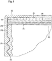
- Figure 1 shows a general structure of the cap according to the invention.
- Figure 1 shows a cap (1) according to the invention with a screw thread (2) for closing a container (3), comprising at least one grid (4) that is applied to the cap inner wall (5) in the cap, and at least one foamed polymer layer (6) which is applied to the grid (4) and at least one further polymer layer (7) which is applied to the foamed polymer layer (6) and which closes the container opening (8).
- the container (3) is preferably closed by pressing the cap (1) with the grid (4), the foamed polymer (6) and the further polymer layer (7).
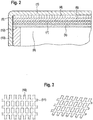
- Figure 2 shows a further embodiment according to the invention in which a seal (9) is used, which additionally seals the container opening (8) at the edge (12) of the opening.
- the polymer layer (7) is placed on the seal (9).
- the polymer layer (7) and the seal (9) are preferably connected to one another. This is preferably done by gluing.
- the foamed polymer layer (6) can move into the open areas of the grid (4).
- the further polymer layer (7) follows the movement of the foamed polymer layer (6) and thereby exposes areas at the edge (12) of the bottle opening, which allow pressure relief via the gap (13) between the container opening and the cap.
- Figure 3 shows the grid (4) with the grid struts (10) and (11).
- the invention makes it possible with extremely little effort and without any structural change in the cap, just by inserting a grid and two different polymers or a composite of these polymers, to install an overpressure prevention device. It is not necessary to carry out structural measures on the cap, so that considerable costs and resources are saved.
- the construction allows a safe avoidance of overpressure without compromising the integrity of the packaging at any point in time.
- a round polyethylene grid (diameter: 6.6 cm, diameter of the grid struts: 2 mm, spacing of the grid struts in the square grid: 10 mm) and a Composite of foamed polyethylene (PE) (thickness: 3 mm, density: 194 kg / m 3 , diameter: 6.6 cm) and a polytetrafluoroethylene layer (PTFE) with a thickness of 0.5 mm (diameter: 6.6 cm), inserted.
- PE foamed polyethylene
- PTFE polytetrafluoroethylene layer
- the cap also had a locking ring to indicate that it was intact before opening.
- a round polyethylene grid (diameter: 6.6 cm, diameter of the grid struts: 2 mm, spacing of the grid struts in the square grid: 10 mm) and a Composite of foamed polyethylene (PE) (thickness: 3 mm, density: 194 kg / m 3 , diameter: 6.6 cm) and a polytetrafluoroethylene layer (PTFE) with a thickness of 0.5 mm (diameter: 6.6 cm), inserted.
- PE foamed polyethylene
- PTFE polytetrafluoroethylene layer
- the cap also had a locking ring to indicate that it was intact before opening.
- An aluminum bottle with a volume of 6 l was closed with a commercially available cap with screw thread with a torque of 6.7 Nm; A pressure of 1.5 bar was generated by means of compressed air and a possible decrease in pressure was observed over a period of 3 days.
- the internal pressure in the bottle was measured by a manometer integrated in the bottle. No pressure relief was measured.
- the cap with inlaid composite comprising foamed polyethylene (PE) (6) and polytetrafluoroethylene layer (PTFE) (7), from Example 1, but without the additional grid (4), was used around a 30 liter glass bottle filled with 3 liters Dimethyl dicarbonate and 1 liter of water to close with a torque of 6.7 Nm. After a pressure build-up of 24 hours, the glass burst at a pressure of 10 bar.
- PE polyethylene
- PTFE polytetrafluoroethylene layer
Landscapes
- Engineering & Computer Science (AREA)
- Mechanical Engineering (AREA)
- Closures For Containers (AREA)
- Packages (AREA)
- Sealing Material Composition (AREA)
Abstract
Description
- Die Erfindung betrifft eine Kappe zum Verschließen von Behältern umfassend zumindest ein Gitter, ein geschäumtes Polymer und mindestens ein weiteres Polymer und Behälter, die mit der erfindungsgemäßen Kappe ausgestattet sind.
- In geschlossenen, insbesondere blickdichten, aber auch transparenten Behältern, wie sie beispielsweise zum Transport und der Lagerung von Chemikalien verwendet werden, besteht für den Zwischen- oder Endverbraucher oftmals der Wunsch etwaigen Überdruck, welcher sind in den Behältern bilden kann, zu vermeiden. Überdruck kann insbesondere entstehen, wenn die Substanzen länger gelagert wurden oder wenn erhöhte Temperaturbelastung die Lagerung beeinträchtigen konnte.
- Dies ist in all den Fällen von entscheidender sicherheitstechnischer Bedeutung, in denen sich zum Beispiel über den Lagerzeitraum bzw. den Transport unerwünschte Veränderungen im Behälter ergeben können. Beispielsweise gibt es viele Chemikalien oder Stoffmischungen, welche sich tendenziell zersetzen können und dabei gasförmige Substanzen abgeben können. Auch ein Zerfall der Stoffe oder Stoffmischungen selbst, in unter Standardbedingungen gasförmige Substanzen, ist bekannt. Die entstehenden Gase können nicht entweichen, denn die Behälter müssen dicht verschlossen sein, beispielsweise um den gefahrlosen Transport sicherzustellen. Je nach Situation besteht damit die Möglichkeit, dass sich durch die angesammelten Gase der Innendruck in dem Behälter erhöht. Der unkontrollierte und unbekannte Innendruck führt dann zu einer Reihe unerwünschter Effekte.
- Beispielsweise kommt es beim Öffnen zu einer schlagartigen Entspannung. Dies wiederum kann dazu führen, dass die im Behälter befindliche Substanz, wenn es eine Flüssigkeit ist, mitgerissen wird, ungewollt in die Umgebung austritt und Personen und Gegenstände verunreinigt.
- Weiter kann durch die ungewollte spontane Expansion der angesammelten Gase, während des Vorgangs der Öffnung, ein Gegenstand, beispielsweise der Verschluss selbst, stark beschleunigt werden und Personen oder Objekte im Umfeld verletzen.
- Weiter kann durch den sich aufbauenden Innendruck eine im Behälter befindliche Flüssigkeit stark mit Gas gesättigt sein. Durch die Entspannung während des Öffnens kann dies beispielsweise zu schlagartigem Schäumen mit vehementem Substanzaustritt führen.
- Weiter kann durch den sich aufbauenden Innendruck auch ohne den Vorgang des Öffnens die mechanische Stabilität des Behälter und der jeweiligen Verpackung in Mitleidenschaft gezogen werden. Der Behälter kann sich unerwünscht verformen oder sogar bersten. Durch die mechanische Beschleunigung der Stücke, während des Berstens, sind weitere Verletzungen möglich, was beispielweise bei Glasbehältern und daraus folgenden Glassplittern sehr leicht zu weitergehenden und ernsten Verletzungen von Personen führen kann.
- Die einfachste aus dem Stand der Technik bekannte Vorrichtung, um Überdruck einfach und sicher zu vermeiden, sind an die Behälter angebrachte Berstscheiben. Diese werden in unterschiedlichsten Ausführungen, beispielsweise von der Firma Fike Deutschland, Innstrasse 28, 68199 Mannheim, vertrieben. Leider wird hier bei erhöhtem Druck die Integrität der Behälter aufgegeben, insofern als die Scheiben nachgeben und zerbrechen. Dadurch besteht die Gefahr, dass der chemische, gegebenenfalls toxische Inhalt, freigesetzt wird. Außerdem sind Berstscheiben aufwendig in der Herstellung. Weiter ist die Einarbeitung der Berstscheibe in bestehende Verpackungslösungen oft sehr aufwendig und für viele der eingesetzten Gebinde für Flüssigkeiten in Flaschenform mit Schraubkappe, aus Kostengründen, nicht auf dem Markt verfügbar.
- Für größere Behältnisse, beispielsweise Tanks, sind nach dem Stand der Technik Überdruckventile bekannt, welche ohne die Integrität der Behältnisse aufzugeben, eine sichere Druckentlastung erlauben. Allerdings sind konstruktionsbedingt derartige Überdruckventile für kleinere Gebinde, wie beispielsweise transparente Flaschen aus Polyethylenterephtalat zu 250, 330, 500, 1000 oder 2000 ml, wie sie in der Getränkeindustrie verwendet werden, nicht bekannt, da diese nur mit einfachen Schraubkappen aus Polythethylen oder Polypropylen verschlossen werden und diese für Überdruckventile konstruktiv nicht einfach eingefügt werden können. Ebenso sind auch für Aluminumflaschen oder Glasflaschen mit Schraubverschluss aus Kunststoff keine einfachen Lösungen mit Überdruckventilen bekannt.
- Aus der
US-B 4121728 ist eine Entlüftungsauskleidung aus geschäumten Polymeren und zwei undurchlässigen Kunststoffschichten bekannt, deren Oberfläche strukturiert ist und z.B. Einkerbungen aufweisen kann. Diese laminierten Kunststoffformen werden dann in runde Plättchen gestanzt und in einer Verschlusskappe angebracht. Die Entlastung bei Überdruck erfolgt jetzt dadurch, dass durch die aufgeprägten Strukturen Hohlräume entstanden sind, die zur Druckableitung genutzt werden und zum Druckausgleich über das Gewinde führen. Diese Form der Entlüftung eignet sich nur zur Entspannung höhere Drücke. Zudem erfordert die Herstellung der Kunststoffschichten technisch aufwendige Prozesse und ist daher nicht ökonomisch. - Es bestand daher die Aufgabe ohne konstruktive Veränderung bestehender Kunststoff, Glas oder Metallflaschen, welches mit Schraubverschlüssen flüssigkeitsdicht verschlossen werden, ein Verschlusssystem zu finden, welche ein Entweichen von Überdruck erlauben würde.
- Überraschend wurde nun ein Verschlusssystem gefunden, mit dem die Nachteile des Standes der Technik überwunden werden können ohne die Verwendung von technisch aufwendigen und schlecht handhabbaren zusätzlichen Bauteilen. Insbesondere erlaubt die Konstruktion die besonders wichtige Anpassung an die erforderlichen Druckverhältnisse.
- Gegenstand der Erfindung ist daher eine Kappe mit Schraubgewinde zum Verschließen eines Behälters, umfassend zumindest ein Gitter, dass in der Kappe auf die Kappeninnenwand aufgebracht ist, und mindestens eine geschäumte Polymerschicht, welche auf das Gitter aufgebracht ist und mindestens eine weitere Polymerschicht die auf die geschäumten Polymerschicht aufgebracht ist und die Behälteröffnung verschließt.
- Die Kappe besteht vorzugsweise aus Polymeren oder Metall. Als Metalle, aus denen die Kappen bestehen können, werden vorzugsweise Edelstahl und Aluminium verwendet. Als Polymere, aus denen die Kappen bestehen können, werden vorzugsweise Polyethylenterephthalat (PET), Polypropylen (PP) oder Polyethylen (PE) oder Mischungen dieser Polymere eingesetzt. Besonders bevorzugt besteht die Kappe aus optisch transparentem, opaken oder eingefärbten Polyethylenterephthalat (PET), Polypropylen (PP) oder Polyethylen (PE) oder Mischungen dieser Polymeren. Noch weiter bevorzugt besteht die Kappe aus Polyethylen. Die Herstellung von Kappen der genannten Art, ist dem Fachmann bekannt. Beispielsweise sind Kappen aus Polyethylenterephthalat (PET), Polypropylen (PP) oder Polyethylen (PE) im Handel erhältlich.
- Die Kappe an sich, ohne den erfindungsgemäßen Einsatz mit zumindest einem Gitter, dass in der Kappe auf die Kappeninnenwand aufgebracht ist, und mindestens eine geschäumte Polymerschicht, welche auf das Gitter aufgebracht ist und mindestens eine weitere Polymerschicht an der die geschäumten Polymerschicht aufgebracht ist und die Behälteröffnung verschließt, ist eine handelsübliche Kappe bzw. ein Deckel mit Schraubverschluss. Die Begriffe Kappe mit Schraubverschluss und Deckel mit Schraubverschluss werden im Sinne der Erfindung synonym verwendet.
- Die Kappe weist ein Schraubgewinde auf mit dem sie auf die Öffnung des Behälters aufgeschraubt werden kann.
- Die Kappe kann vorzugsweise auch durch Sicherheitsringe modifiziert sein. Sicherheitsringe dienen zum Anzeigen einer Erstöffnung einer Flasche und sind zum Beispiel aus der
WO-A-9213773 - Bei dem Behälter handelt es sich vorzugsweise um Flaschen. Die Behälter weisen vorzugsweise ein Volumen von 250, 330, 500, 1000, 2000, 6000, 10000 ml oder 40000 ml auf. Besonders bevorzugt weisen die Behälter ein Volumen von 2000 ml bis 40000 ml auf. Der Behälter kann aus Polymeren, wie vorzugsweise Polyethylenterpthalat, Polypropylen oder Polyethylen, oder aus Metall, wie vorzugsweise Aluminium und Edelstahl oder aus Glas bestehen. Besonders bevorzugt besteht der Behälter mindestens zu 95 Gew. % aus Aluminium bezogen auf das Gesamtgewicht des Behälters ohne Verschluss, oder aus Glas. Die Erfindung betrifft ebenfalls den Behälter umfassend die erfindungsgemäße Kappe. Vorzugsweise wird der Behälter mit der erfindungsgemäßen Kappe zum Transport und der Lagerung von Chemikalien, besonders bevorzugt zum Transport und Lagerung von flüssigem Dimethyldicarbonat verwendet. Es hat sich zudem gezeigt, dass gerade auch bei nur teilweise gefüllten Behältern, die Druckableitung mit der erfindungsgemäßen Kappe überzeugend funktioniert.
- Daher ist von der Erfindung ebenfalls ein Behälter mit der erfindungsgemäßen Kappe umfasst, bei dem der Behälter teilweise oder vollständig mit flüssigem Dimethyldicarbonat gefüllt ist. Bevorzugt ist der Behälter teilweise befüllt.
- Das Gitter kann sowohl formstabil sein als auch elastomere Eigenschaften aufweisen. Es kann beispielsweise auch aus geschäumtem Polymeren bestehen.
- Das Gitter besteht vorzugsweise aus Polymeren oder Metall. Als Metalle, aus denen das Gitter bestehen kann, werden vorzugsweise Edelstahl und Aluminium verwendet. Als Polymere, aus denen das Gitter bestehen kann, werden vorzugsweise Polyethylenterephthalat (PET), Polypropylen (PP), Polyethylen (PE), Polycarbonat oder Polytetrafluorethylen (PTFE) oder Mischungen dieser Polymere eingesetzt. Besonders bevorzugt besteht das Gitter aus Polypropylen (PP) oder Polyethylen (PE) oder Mischungen dieser Polymeren.
- Die Gitterstreben des Gitters können rechteckig oder rund geformt sein oder eine andere Form aufweisen. Die Gitterstreben des Gitters weisen bevorzugt eine runde Form auf.
- Die Gitterstreben können senkrecht zueinander angeordnet sein, können aber auch andere Winkel aufweisen, wie beispielsweise und vorzugsweise 55° bis 65 °, 85 ° bis 95° oder 110 ° bis 130°. Besonders bevorzugt sind die Gitterstreben in einem Winkel von 85 ° bis 95° zueinander angeordnet.
- Vorzugsweise haben die Gitterstreben des Gitters eine Breite von 0.2 mm bis 5 mm und eine Höhe von 0.2 mm bis 5 mm, falls es sich um im Wesentlichen rechteckige Gitterstreben handelt. Besonders bevorzugt haben die Gitterstreben des Gitters eine Breite von 0.5 mm bis 2 mm hat und eine Höhe von 0.5 mm bis 2 mm, falls es sich um im Wesentlichen rechteckige Gitterstreben handelt. Vorzugsweise weisen beide Gitterstreben im Rahmen einer Fehlerbreite von 5 %, die gleiche Breite und Höhe auf. Vorzugsweise haben die Gitterstreben des Gitters einen Durchmesser von 0.2 mm bis 5 mm, besonders bevorzugt einen Durchmesser von 0.5 mm bis 2 mm auf, falls es sich im Wesentlichen um runde Gitterstreben handelt. Der Abstand der Gitterstreben beträgt vorzugsweise 2 mm bis 20 mm. Vorzugsweise ist das Verhältnis zwischen dem Durchmesser der Gitterstrebe und dem Raum zwischen den Gitterstreben 1 : 7 bis 1 :12. Vorzugsweise handelt es sich bei dem Gitter um ein Polyethylengitter mit runden Gitterstreben mit einem Durchmesser von 2 mm und einem Abstand von 10 mm, die rechtwinkelig zueinander ausgerichtet sind.
- Das Gitter kann auf unterschiedliche Arten hergestellt werden. Beispielsweise können Gitter aus Polymeren durch einen Extrusionsprozess hergestellt werden. Weiterhin können polymere Gitter durch einen Walzprozess mit entsprechend geformten Walzen hergestellt werden. Des Weiteren können polymere Gitter durch einen Fräsprozess aus einer Kunststoffschicht hergestellt werden. Ein Web oder Verklebprozess ist ebenso geeignet. Gitter aus Polymeren sind beispielsweise gewerblich erhältlich von HaGa-Welt GmbH & Co. KG, Lange Str. 5, 31171 Nordstemmen, Deutschland. Gitter aus Metallen können beispielsweise durch Guss- oder Drahterodierungsverfahren hergestellt werden.
- Vorzugsweise besitzt das Gitter eine runde Form um im Wesentlichen passgenau an die Kappeninnenwand angepasst werden zu können. Vorzugsweise ist der Durchmesser des Gitters 2 cm bis 10 cm. Besonders bevorzugt ist der Durchmesser des Gitters 6.6 cm +/- 0,2 cm. Besonders bevorzugt weist das Gitter Gitterstreben mit einem Durchmesser von 2 mm +/- 0,1 mm mit einem Gitterabstand von 10 mm +/- 0,5 mm auf. Das Gitter könnte eine Randbegrenzung aufweisen, damit es dicht mit der Kappeninnenwand abschließen kann. Diese Randbegrenzung besteht vorzugsweise aus dem selben Polymeren, aus dem das Gitter besteht. Vorzugsweise besitzt das Gitter keine solche Randbegrenzung.
- Im "Wesentlichen" bedeutet im Sinne der vorliegenden Erfindung, dass die Größendifferenz zwischen zwei zu vergleichenden Bauteilen nicht mehr als 5 %, bevorzugt nicht mehr als 1 %, abweichen.
- Geeignete geschäumte Polymere, aus denen die geschäumte Polymerschicht bestehen kann, sind vorzugsweise Polypropylen, Polyethylen, High Density Polyethylen (HDPE), Low Density Polyethylen (LDPE), High Density Polypropylen (HDPP) oder Low Density Polypropylen (LDPP), Polyethylenterephthalat, Polystyrene, Polyurethan, Polycarbonat, Ethylen-Propylen-Dien-Kautschuk (EPDM), oder fluorierte geschäumte Polymere, wie vorzugsweise Fluorkautschuk (FKM) nach DIN ISO 1629 und Fluorkautschuck nach ASTM D 1418, Polytetrafluorethylen (PTFE) oder anderer geschäumte teil- oder per-fluorierte Kohlenwasserstoffe auf Basis von Vinyliden(di)fluorid oder Mischungen dieser geschäumte Polymeren. Als geschäumte Polymeren werden vorzugsweise Polystyrol, Polyethylen oder Polypropylen eingesetzt. Die Herstellung von geschäumten Polymeren ist aus dem Stand der Technik bekannt und erfolgt daher nach bekannten Verfahren. Besonders bevorzugt besteht die geschäumte Polymerschicht aus geschäumtem Polyethylen, geschäumtem Polyethylen, geschäumtem Polypropylen oder geschäumtem Polypropylen.
- Vorzugsweise weist der geschäumte Polymer eine Dichte von 45 bis 450 kg/m3. Besonders bevorzugt 100 kg/ m3 bis 250 kg/ m3.
- Vorzugsweise besitzt die geschäumte Polymerschicht eine runde Form um im Wesentlichen passgenau auf das Gitter angepasst zu sein. Vorzugsweise ist der Durchmesser der geschäumten Polymerschicht 2 cm bis 10 cm. Besonders bevorzugt ist der Durchmesser der geschäumten Polymerschicht 6.6 cm +/- 0,2 cm. Vorzugsweise besitzt die geschäumte Polymerschicht eine Dicke von 0.2 mm bis 5 mm. Besonders bevorzugt besitzt die geschäumte Polymerschicht eine Dicke von 3 mm +/- 0,15 mm.
- Auf die geschäumte Polymerschicht wird eine weitere Polymerschicht aufgebracht. Diese Polymerschicht besteht vorzugsweise aus Polytetrafluorethylen (PTFE). Es können aber auch andere Polymere verwendet werden. Diese Polymere müssen die Eigenschaft aufweisen, die geschäumte Polymerschicht gegenüber dem Behälterinhalt abzutrennen und wirken daher als Dichtung.
- Vorzugsweise besitzt die weitere Polymerschicht eine runde Form um im Wesentlichen passgenau auf die geschäumte Polymerschicht angepasst werden zu können. Vorzugsweise ist der Durchmesser der weiteren Polymerschicht 2 cm bis 10 cm. Besonders bevorzugt ist der Durchmesser der weiteren Polymerschicht 6.6 cm +/- 0,2 cm. Vorzugsweise besitzt die Polymerschicht eine Dicke von 0.01 mm bis 4 mm. Besonders bevorzugt besitzt die weitere Polymerschicht eine Dicke von 0,5 mm +/- 0,025 mm. Die Polymerschicht kann durch Auflegen mit der geschäumten Polymerschicht in Kontakt gebracht werden und nicht weiter befestigt werden. Vorzugsweise wird die weitere Polymerschicht an der geschäumten Polymerschicht befestigt.
- Vorzugsweise wird das geschäumte Polymer und die weitere Polymerschicht mittels eines Klebers verbunden.
- Als Kleber werden vorzugsweise Kleber auf Basis von Cyanacrylate, Methylmethacrylate, ungesättigte Polyester, Epoxidharze, Phenolharze, Polyimide, Polysulfide, Bismaleimide und 1-Komponenten- und 2-Komponenten kondensationsvernetzende Silikone eingesetzt.
- Die geschäumte Polymerschicht und die weitere Polymerschicht werden vorzugsweise als Komposit eingesetzt. Vorzugsweise wird das Komposit durch Laminierung der geschäumten Polymerschicht und der weiteren Polymerschicht in Gegenwart eines Klebers hergestellt. Besonders bevorzugt wird als Kleber ein Cyanacrylatkleber verwendet.
- Das Komposit wird vorzugsweise auf das Gitter aufgelegt.
- Zwischen der Behälteröffnung und der Polymerschicht kann eine Dichtung oder ein Dichtring aufgelegt werden. Die Dichtung besteht vorzugsweise aus Polyethylen. Vorzugsweise besitzt die Dichtung einen Durchmesser, der im Wesentlichen mit dem Durchmesser der weiteren Polymerschicht übereinstimmt. Vorzugsweise besitzt die Dichtung eine Dicke, die im Wesentlichen mit der Dicke der weiteren Polymerschicht übereinstimmt. Diese Dichtung wird vorzugsweise ebenfalls durch einen Kleber an der weiteren Polymerschicht fixiert. Ebenso könnte die Fixierung der Dichtung auf der Polymerschicht und der Behälteröffnung, insbesondere des Behälterrandes, durch die mechanische Kraft, die beim Verschließen der Behälteröffnung mit der Kappe wirkt, also durch Einklemmen der Dichtung, erfolgen. Bevorzugt wird keine Dichtung zwischen der Behälteröffnung und der Polymerschicht eingefügt. Bevorzugt bildet die Polymerschicht die Verschlussschicht der Behälteröffnung. Vorzugsweise dient die Polymerschicht als Dichtung.
- Vorzugsweise erfolgt die Fixierung der geschäumten Polymerschicht, der weiteren Polymerschicht und des Gitters auf der Behälteröffnung durch Verschließen des Behälters mit der Kappe.
- Vorzugsweise erfolgt das Verschließen des Behälters mit der erfindungsgemäßen Kappe mit einem maximalen Anzugsdrehmoment M, wobei für das maximale Anzugsdrehmoment M vorzugsweise 4 Nm ≤ M ≤ 8 Nm, besonders bevorzugt 5 Nm ≤ M ≤ 7 Nm, gilt.
- Mit Hilfe der erfindungsgemäßen Kappe können Drücke ≥ 1,2 bar abgeführt werden.
- Im Folgenden wird die Erfindung ohne Beschränkung des allgemeinen Erfindungsgedankens unter Bezugnahme auf die Figuren näher erläutert.
-
Figur 1 zeigt einen allgemeinen Aufbau der erfindungsgemäßen Kappe. -
Figur 1 zeigt dabei eine erfindungsgemäße Kappe (1) mit Schraubgewinde (2) zum Verschließen eines Behälters (3), umfassend zumindest ein Gitter (4), dass in der Kappe auf die Kappeninnenwand (5) aufgebracht ist, und mindestens eine geschäumte Polymerschicht (6), welche auf das Gitter (4) aufgebracht ist und mindestens eine weitere Polymerschicht (7), die auf die geschäumte Polymerschicht (6) aufgebracht ist und die die Behälteröffnung (8) verschließt. - Durch Anpressen der Kappe (1) mit dem Gitter (4), dem geschäumten Polymeren (6) und der weiteren Polymerschicht (7) wird vorzugsweise der Behälter (3) verschlossen.
-
Figur 2 zeigt eine weitere erfindungsgemäße Ausführungsform, bei der eine Dichtung (9) eingesetzt wird, die Behälteröffnung (8) am Rand (12) der Öffnung zusätzlich abdichtet. Bei dieser Ausführungsform wird die Polymerschicht (7) auf die Dichtung (9) aufgelegt. Vorzugsweise wird die Polymerschicht (7) und die Dichtung (9) miteinander verbunden. Dies geschieht vorzugsweise durch verkleben. - Durch den Druck kann sich die geschäumte Polymerschicht (6) in die offenen Bereiche des Gitters (4) bewegen. Die weitere Polymerschicht (7) folgt der Bewegung der geschäumten Polymerschicht (6) und gibt dadurch Bereiche am Rand (12) der Flaschenöffnung frei, die eine Druckentlastung über den Spalt (13) zwischen Behälteröffnung und Kappe ermöglichen.
-
Figur 3 zeigt das Gitter (4) mit den Gitterstreben (10) und (11). - Durch die Erfindung ist es möglich mit extrem geringem Aufwand und ohne jegliche strukturelle Veränderung der Kappe, nur durch Einlegen eines Gitters und zweier voneinander unterschiedlicher Polymeren oder eines Komposits dieser Polymeren, eine Überdruckverhinderung einzubauen. Strukturelle Maßnahmen an der Kappe sind nicht nötig durchzuführen, so dass erhebliche Kosten und Ressourcen eingespart werden.
- Die Konstruktion erlaubt eine sichere Vermeidung von Überdruck, ohne zu irgendeinem Zeitpunkt die Integrität der Verpackung aufzugeben.
- In eine handelsübliche Verschluss-Kappe von 6.6 cm Durchmesser mit Schraubgewinde, welche aus Polyethylen gefertigt war, wurde ein rundes Gitter aus Polyethylen (Durchmesser: 6.6 cm, Durchmesser der Gitterstreben: 2 mm, Abstand der Gitterstreben im quadratischen Gitter: 10 mm) und ein Komposit aus geschäumtem Polyethylen (PE) (Dicke: 3 mm, Dichte: 194 kg/m3, Durchmesser: 6.6 cm) und einer Polytetrafluorethylenschicht (PTFE) mit einer Dicke von 0.5 mm (Durchmesser: 6.6 cm), eingelegt. Die Kappe trug außerdem einen Sicherungsring zur Indikation der Unversehrtheit vor Öffnung.
- Danach wurde eine leere Aluminiumflasche mit einem Volumen von 6 I mit der obigen Kappe mit einem Anzugsdrehmoment von 6.7 Nm verschlossen und der Flascheninnendruck langsam , durch Zugabe von Druckluft, auf 1,5 bar erhöht. Der Flascheninnendruck wurde durch ein in der Flasche integriertes Manometer gemessen. Bei Erreichen von 1,5 bar wurde eine Druckentlastung festgestellt; durch den Druck konnte sich die geschäumte Polymerschicht (6) in die offenen Bereiche des Gitters (Gitters) bewegen. Die Polytetrafluorethylenschicht (7) folgt der Bewegung der geschäumten Polymerschicht (6) und gibt dadurch Bereiche am Rand (12) der Flaschenöffnung frei, die eine Druckentlastung über den Spalt (13) zwischen Behälteröffnung und Kappe ermöglichen. Der Druck nahm innerhalb von 15 Minuten von 1,5 bar auf 1,2 bar ab.
- Ist der Druck entsprechend entlastet schließen sich die Polymerschichten wieder.
- In eine handelsübliche Verschluss-Kappe von 6.6 cm Durchmesser mit Schraubgewinde, welche aus Polyethylen gefertigt war, wurde ein rundes Gitter aus Polyethylen (Durchmesser: 6.6 cm, Durchmesser der Gitterstreben: 2 mm, Abstand der Gitterstreben im quadratischen Gitter: 10 mm) und ein Komposit aus geschäumtem Polyethylen (PE) (Dicke: 3 mm, Dichte: 194 kg/m3, Durchmesser: 6.6 cm) und einer Polytetrafluorethylenschicht (PTFE) mit einer Dicke von 0.5 mm (Durchmesser: 6.6 cm), eingelegt. Die Kappe trug außerdem einen Sicherungsring zur Indikation der Unversehrtheit vor Öffnung.
- Danach wurde eine Aluminiumflasche mit einem Volumen von 6 I mit der obigen Kappe mit einem Anzugsdrehmoment von 6.7 Nm verschlossen. Die Flasche enthielt 6 kg Dimethyldicarbonat (Velcorin, Lanxesss Deutschland GmbH, Charge CHWV5547, Reinheit > 99.8%). Nach Befüllen und Verschließen wurde die Flasche 12 Monate bei Raumtemperatur gelagert. Danach wurde die Flasche 6 Monate bei 50°C gelagert. Danach wurde die Flasche geöffnet. Beim Öffnen war die Flasche unversehrt und es konnte kein Druckaufbau ≥ 1,2 bar bemerkt werden. Die Reinheit des DMDC betrug nur noch 90%. Das bei der partiellen Zersetzung des DMDC gebildete CO2 konnte durch die erfindungsgemäße Kappe entweichen.
- Der Versuch wurde mit einer 3 I Glasflasche, enthaltend 3 kg Dimethyldicarbonat, wiederholt. Auch in diesem Fall konnte bei Öffnung kein Druckaufbau ≥ 1,2 bar beobachtet werden und die Flasche blieb unversehrt.
- Eine Aluminiumflasche mit einem Volumen von 6 I wurde mit einer handelsüblichen Kappe mit Schraubgewinde mit einem Drehmoment von 6.7 Nm verschlossen; mittels Druckluft wurde ein Druck von 1,5 bar erzeugt und eine eventuelle Druckabnahme über einen Zeitraum von 3 Tagen beobachtet. Der Flascheninnendruck wurde durch ein in der Flasche integriertes Manometer gemessen. Es wurde keine Druckentlastung gemessen.
- Die Kappe mit eingelegtem Komposit umfassend geschäumtes Polyethylen (PE) (6) und Polytetrafluorethylenschicht (PTFE) (7), aus Beispiel 1, jedoch ohne das zusätzliche Gitter (4), wurde verwendet um eine 30 Liter Glas-Flasche, gefüllt mit 3 Liter Dimethyldicarbonat und 1 Liter Wasser, mit einem Drehmoment von 6.7 Nm zu verschließen. Nach 24 h Druckaufbau zerplatzte das Glas bei einem Druck von 10 bar.
Claims (15)
- Kappe (1) mit Schraubgewinde (2) zum Verschließen eines Behälters (3), umfassend zumindest ein Gitter (4), das in der Kappe auf die Kappeninnenwand (5) aufgebracht ist, und mindestens eine geschäumte Polymerschicht (6), welche auf das Gitter (4) aufgebracht ist und mindestens eine weitere Polymerschicht (7), die auf der geschäumten Polymerschicht (6) aufgebracht ist und die die Behälteröffnung (8) verschließt.
- Kappe gemäß Anspruch 1, dadurch gekennzeichnet, dass im Gitter (4) die im Wesentlichen runden Gitterstreben einen Durchmesser von 0.2 mm bis 5 mm haben.
- Kappe gemäß einem der Ansprüche 1 bis 2, dadurch gekennzeichnet, dass die geschäumte Polymerschicht (6) mindestens ein Polymer ausgewählt aus der Gruppe Polypropylen, Polyethylen, High Density Polyethylen (HDPE), Low Density Polyethylen (LDPE), High Density Polypropylen (HDPP), Low Density Polypropylen (LDPP), Polyethylenterephthalat, Polystyrene, Polyurethan, Polycarbonat, Ethylen-Propylen-Dien-Kautschuk (EPDM), oder fluorierte geschäumte Polymere, wie vorzugsweise Fluorkautschuk (FKM) nach DIN ISO 1629 und Fluorkautschuck nach ASTM D 1418, Polytetrafluorethylen (PTFE) oder anderer geschäumte teil- oder per-fluorierte Kohlenwasserstoffe auf Basis von Vinyliden(di)fluorid oder Mischungen dieser geschäumte Polymeren, umfasst.
- Kappe gemäß einem der Ansprüche 1 bis 3, dadurch gekennzeichnet, dass die geschäumte Polymerschicht (6) eine Dichte von 45 bis 450 kg/m3 aufweist.
- Kappe gemäß einem der Ansprüche 1 bis 4, dadurch gekennzeichnet, dass die Polymerschicht (7) aus Polytetrafluorethylen besteht.
- Kappe gemäß einem der Ansprüche 1 bis 5, dadurch gekennzeichnet, dass die geschäumte Polymerschicht (6) mit der Polymerschicht (7) mit Hilfe eines Klebers verbunden wird.
- Kappe gemäß Anspruch 6, dadurch gekennzeichnet, dass Kleber auf Basis von Cyanacrylate, Methylmethacrylate, ungesättigte Polyester, Epoxidharze, Phenolharze, Polyimide, Polysulfide, Bismaleimide und 1-Komponenten- und 2-Komponenten Kondensationsvernetzende Silikone und Glutinleim oder Mischungen dieser Kleber eingesetzt werden.
- Kappe gemäß einem der Ansprüche 1 bis 7, dadurch gekennzeichnet, dass das Gitter (4) aus Polypropylen (PP) oder Polyethylen (PE) oder Mischungen dieser Polymeren besteht.
- Kappe gemäß einem der Ansprüche 1 bis 8, dadurch gekennzeichnet, dass als Dichtung auf den Rand (12) der Behälteröffnung (8) eine Polyethylendichtung eingesetzt wird.
- Kappe gemäß einem der Ansprüche 1 bis 9, dadurch gekennzeichnet, dass die Kappe (1) aus Polyethylenterephthalat (PET), Polypropylen (PP) oder Polyethylen (PE) oder Mischungen dieser Polymeren besteht.
- Behälter umfassend die Kappe gemäß mindestens einem Anspruch 1 bis 10.
- Behälter gemäß Anspruch 11, dadurch gekennzeichnet, dass der Behälter zumindest teilweise mit flüssigem Dimethyldicarbonat gefüllt ist.
- Behälter gemäß Anspruch 11 oder 12, dadurch gekennzeichnet, dass die Kappe mit einem maximalen Anzugsdrehmoment M von 4 Nm ≤ M ≤ 8 Nm verschlossen wird.
- Behälter gemäß einem der Ansprüche 10 bis 13, dadurch gekennzeichnet, dass der Behälter einen Aluminiumgehalt von ≥ 95 Gew.% bezogen auf das Gesamtgewicht des Behälters ohne Kappe aufweist.
- Verwendung der Kappe gemäß einem der Ansprüche 1 bis 10 zum Verschließen von Behältern.
Priority Applications (8)
| Application Number | Priority Date | Filing Date | Title |
|---|---|---|---|
| EP20178455.0A EP3919408B1 (de) | 2020-06-05 | 2020-06-05 | Kappen mit sicherheitsfunktion gegen überdruck |
| ARP210101481A AR122490A1 (es) | 2020-06-05 | 2021-06-01 | Tapas con función de seguridad para la prevención de presión excesiva |
| BR102021010662-0A BR102021010662B1 (pt) | 2020-06-05 | 2021-06-01 | Tampas com função de segurança para prevenção de pressão excessiva |
| AU2021203644A AU2021203644B2 (en) | 2020-06-05 | 2021-06-03 | Caps with safety function for prevention of excessive pressure |
| CN202110627015.0A CN113753401B (zh) | 2020-06-05 | 2021-06-04 | 具有防止过压的安全功能的盖 |
| ZA2021/03841A ZA202103841B (en) | 2020-06-05 | 2021-06-04 | Caps with safety function for prevention of excessive pressure |
| JP2021094336A JP7434212B2 (ja) | 2020-06-05 | 2021-06-04 | 過圧を防ぐための安全機能を備えたキャップ |
| US17/339,943 US20210380317A1 (en) | 2020-06-05 | 2021-06-05 | Caps with safety function for prevention of excessive pressure |
Applications Claiming Priority (1)
| Application Number | Priority Date | Filing Date | Title |
|---|---|---|---|
| EP20178455.0A EP3919408B1 (de) | 2020-06-05 | 2020-06-05 | Kappen mit sicherheitsfunktion gegen überdruck |
Publications (2)
| Publication Number | Publication Date |
|---|---|
| EP3919408A1 true EP3919408A1 (de) | 2021-12-08 |
| EP3919408B1 EP3919408B1 (de) | 2024-03-13 |
Family
ID=71016387
Family Applications (1)
| Application Number | Title | Priority Date | Filing Date |
|---|---|---|---|
| EP20178455.0A Active EP3919408B1 (de) | 2020-06-05 | 2020-06-05 | Kappen mit sicherheitsfunktion gegen überdruck |
Country Status (7)
| Country | Link |
|---|---|
| US (1) | US20210380317A1 (de) |
| EP (1) | EP3919408B1 (de) |
| JP (1) | JP7434212B2 (de) |
| CN (1) | CN113753401B (de) |
| AR (1) | AR122490A1 (de) |
| AU (1) | AU2021203644B2 (de) |
| ZA (1) | ZA202103841B (de) |
Citations (5)
| Publication number | Priority date | Publication date | Assignee | Title |
|---|---|---|---|---|
| US2542741A (en) * | 1949-03-26 | 1951-02-20 | Armstrong Cork Co | Vent-type bottle closure |
| US2602559A (en) * | 1948-09-24 | 1952-07-08 | Armstrong Cork Co | Venting closure and liner therefor |
| US2946471A (en) * | 1957-11-04 | 1960-07-26 | Owens Illinois Glass Co | Venting closure cap |
| US4121728A (en) | 1976-12-10 | 1978-10-24 | Selig Sealing Products | Venting liners |
| WO1992013773A1 (de) | 1991-02-11 | 1992-08-20 | Mhk Max Hübner Gmbh | Flaschenkappe mit sicherungsring |
Family Cites Families (14)
| Publication number | Priority date | Publication date | Assignee | Title |
|---|---|---|---|---|
| DE2403244C3 (de) * | 1974-01-24 | 1980-12-04 | Riedel-De Haen Ag, 3016 Seelze | Für Gase permeable, flüssigkeitsdichte Absperrvorrichtung |
| JPS62125751U (de) * | 1986-02-01 | 1987-08-10 | ||
| US5579936A (en) * | 1994-10-31 | 1996-12-03 | The Clorox Company | Reverse channel bi-directional venting liner |
| CN101421166B (zh) * | 2006-04-17 | 2011-06-15 | 大和制罐株式会社 | 带螺纹的罐容器 |
| CN101511578A (zh) * | 2006-07-14 | 2009-08-19 | 陶氏环球技术公司 | 各向异性泡沫-薄膜复合结构 |
| PL2051913T3 (pl) * | 2006-08-15 | 2011-03-31 | Akzo Nobel Nv | Pokrywa odpowietrzająca i pojemnik z taką pokrywą odpowietrzającą |
| KR20090018494A (ko) * | 2007-08-17 | 2009-02-20 | 삼화화학공업주식회사 | 폴리에스테르 부직포를 이용한 탁주용기 밀폐 뚜껑 용패킹과 그 제조방법 |
| US9708110B2 (en) * | 2008-03-12 | 2017-07-18 | Dewal Industries, Llc | Venting liner and method |
| KR101367205B1 (ko) * | 2009-09-23 | 2014-03-12 | 현봉석 | 가스배출용 패킹 |
| CN202265032U (zh) * | 2011-10-10 | 2012-06-06 | 杜斌 | 防水透气电磁封口膜 |
| US20130341325A1 (en) * | 2012-06-20 | 2013-12-26 | Juan E. Bruna | Scent permeation container seal, container including said seal and methods of making said seal and said container |
| JP6650357B2 (ja) * | 2016-06-30 | 2020-02-19 | 株式会社吉野工業所 | ガス抜き機構付き容器 |
| IT201700073534A1 (it) * | 2017-06-30 | 2018-12-30 | Mario Gaia | Tappo a vite per bottiglie di vino |
| KR102155248B1 (ko) * | 2018-07-18 | 2020-09-11 | 대상 주식회사 | 가스 배출용 패킹시트 및 이를 포함하는 식품 용기 |
-
2020
- 2020-06-05 EP EP20178455.0A patent/EP3919408B1/de active Active
-
2021
- 2021-06-01 AR ARP210101481A patent/AR122490A1/es active IP Right Grant
- 2021-06-03 AU AU2021203644A patent/AU2021203644B2/en active Active
- 2021-06-04 ZA ZA2021/03841A patent/ZA202103841B/en unknown
- 2021-06-04 JP JP2021094336A patent/JP7434212B2/ja active Active
- 2021-06-04 CN CN202110627015.0A patent/CN113753401B/zh active Active
- 2021-06-05 US US17/339,943 patent/US20210380317A1/en not_active Abandoned
Patent Citations (5)
| Publication number | Priority date | Publication date | Assignee | Title |
|---|---|---|---|---|
| US2602559A (en) * | 1948-09-24 | 1952-07-08 | Armstrong Cork Co | Venting closure and liner therefor |
| US2542741A (en) * | 1949-03-26 | 1951-02-20 | Armstrong Cork Co | Vent-type bottle closure |
| US2946471A (en) * | 1957-11-04 | 1960-07-26 | Owens Illinois Glass Co | Venting closure cap |
| US4121728A (en) | 1976-12-10 | 1978-10-24 | Selig Sealing Products | Venting liners |
| WO1992013773A1 (de) | 1991-02-11 | 1992-08-20 | Mhk Max Hübner Gmbh | Flaschenkappe mit sicherungsring |
Also Published As
| Publication number | Publication date |
|---|---|
| US20210380317A1 (en) | 2021-12-09 |
| JP2021193037A (ja) | 2021-12-23 |
| AR122490A1 (es) | 2022-09-14 |
| EP3919408B1 (de) | 2024-03-13 |
| AU2021203644B2 (en) | 2023-01-19 |
| BR102021010662A2 (pt) | 2022-01-11 |
| CN113753401A (zh) | 2021-12-07 |
| JP7434212B2 (ja) | 2024-02-20 |
| ZA202103841B (en) | 2022-09-28 |
| CN113753401B (zh) | 2023-07-14 |
| AU2021203644A1 (en) | 2021-12-23 |
Similar Documents
| Publication | Publication Date | Title |
|---|---|---|
| DE2403244C3 (de) | Für Gase permeable, flüssigkeitsdichte Absperrvorrichtung | |
| EP0803445B1 (de) | Dichtungsscheibe für eine Verschlusskappe für Behältnisse | |
| EP0960054B2 (de) | Pet-flasche mit einem kunststoffschraubverschluss | |
| DE2615115A1 (de) | Deckel fuer einmachgefaesse | |
| EP2032459A1 (de) | Dichtscheibe mit einer sauerstoffabsorbierenden substanz | |
| DE3307904A1 (de) | Schraubkappe | |
| DE102012020529A1 (de) | Wiederverschließbares Ausgießelement für eine Verpackung und Dorn eines drehbaren Dornrades einer Verpackungsmaschine zur Aufnahme eines solchen Ausgießelementes und Kombination von Ausgießelement und Dorn | |
| WO2012080190A1 (de) | Verfahren zur befüllung einer kavität, insbesondere eines blisters einer blisterverpackung, mit einer flüssigkeit sowie halbzeug zur verwendung in einem solchen verfahren | |
| DE2245121C3 (de) | Behälterverschluß aus Blech | |
| EP3919408B1 (de) | Kappen mit sicherheitsfunktion gegen überdruck | |
| DE69312545T2 (de) | Verschleissfester Stöpsel zur Vermeidung des Erzeugungs von Teilchen beim Durchbohren | |
| DE2424354A1 (de) | Fluessigkeitsbehaelter mit perforierbarem sperrverschluss | |
| CH711328A2 (de) | Kapsel mit einem vorzugsweise rotationssymmetrisch ausgebildeten Kapselkörper. | |
| DE212013000188U1 (de) | Druckbeständiger Behälterverschluss | |
| EP1545998B1 (de) | Schraubkappe f r unter druck stehende beh lter | |
| AT524056B1 (de) | Schraubverschluss für Behälter | |
| EP0759401A1 (de) | Entgasungsverschluss | |
| DE68909694T2 (de) | Polymerische Zusammensetzungen und ihre Anwendung für Behälterverschlüsse. | |
| EP3636964A1 (de) | Kappen mit druckanzeige für behälter | |
| DE102007058126A1 (de) | Spreizdichtung, insbesondere für Gase | |
| EP0671339B1 (de) | Spundstopfen mit Entgasungseinrichtung | |
| EP2268556A2 (de) | Schraubverschluss für flaschen | |
| DE102012103354A1 (de) | Behälterverschluss sowie Vorrichtung und Verfahren zu dessen Herstellung | |
| DE922691C (de) | Verschluss von Aufbewahrungsbehaeltern fuer Atemschutzgeraete, insbesondere fuer Filterselbstretter | |
| DE2341728A1 (de) | Verfahren zum verschliessen einer flasche oder eines aehnlichen behaelters und vorrichtung hierfuer |
Legal Events
| Date | Code | Title | Description |
|---|---|---|---|
| PUAI | Public reference made under article 153(3) epc to a published international application that has entered the european phase |
Free format text: ORIGINAL CODE: 0009012 |
|
| STAA | Information on the status of an ep patent application or granted ep patent |
Free format text: STATUS: THE APPLICATION HAS BEEN PUBLISHED |
|
| AK | Designated contracting states |
Kind code of ref document: A1 Designated state(s): AL AT BE BG CH CY CZ DE DK EE ES FI FR GB GR HR HU IE IS IT LI LT LU LV MC MK MT NL NO PL PT RO RS SE SI SK SM TR |
|
| B565 | Issuance of search results under rule 164(2) epc |
Effective date: 20201210 |
|
| STAA | Information on the status of an ep patent application or granted ep patent |
Free format text: STATUS: REQUEST FOR EXAMINATION WAS MADE |
|
| 17P | Request for examination filed |
Effective date: 20220608 |
|
| RBV | Designated contracting states (corrected) |
Designated state(s): AL AT BE BG CH CY CZ DE DK EE ES FI FR GB GR HR HU IE IS IT LI LT LU LV MC MK MT NL NO PL PT RO RS SE SI SK SM TR |
|
| GRAP | Despatch of communication of intention to grant a patent |
Free format text: ORIGINAL CODE: EPIDOSNIGR1 |
|
| STAA | Information on the status of an ep patent application or granted ep patent |
Free format text: STATUS: GRANT OF PATENT IS INTENDED |
|
| INTG | Intention to grant announced |
Effective date: 20231114 |
|
| GRAS | Grant fee paid |
Free format text: ORIGINAL CODE: EPIDOSNIGR3 |
|
| GRAA | (expected) grant |
Free format text: ORIGINAL CODE: 0009210 |
|
| STAA | Information on the status of an ep patent application or granted ep patent |
Free format text: STATUS: THE PATENT HAS BEEN GRANTED |
|
| AK | Designated contracting states |
Kind code of ref document: B1 Designated state(s): AL AT BE BG CH CY CZ DE DK EE ES FI FR GB GR HR HU IE IS IT LI LT LU LV MC MK MT NL NO PL PT RO RS SE SI SK SM TR |
|
| REG | Reference to a national code |
Ref country code: GB Ref legal event code: FG4D Free format text: NOT ENGLISH |
|
| REG | Reference to a national code |
Ref country code: CH Ref legal event code: EP |
|
| REG | Reference to a national code |
Ref country code: DE Ref legal event code: R096 Ref document number: 502020007301 Country of ref document: DE |
|
| REG | Reference to a national code |
Ref country code: IE Ref legal event code: FG4D Free format text: LANGUAGE OF EP DOCUMENT: GERMAN |
|
| P01 | Opt-out of the competence of the unified patent court (upc) registered |
Effective date: 20240516 |
|
| PG25 | Lapsed in a contracting state [announced via postgrant information from national office to epo] |
Ref country code: LT Free format text: LAPSE BECAUSE OF FAILURE TO SUBMIT A TRANSLATION OF THE DESCRIPTION OR TO PAY THE FEE WITHIN THE PRESCRIBED TIME-LIMIT Effective date: 20240313 |
|
| REG | Reference to a national code |
Ref country code: LT Ref legal event code: MG9D |
|
| PG25 | Lapsed in a contracting state [announced via postgrant information from national office to epo] |
Ref country code: GR Free format text: LAPSE BECAUSE OF FAILURE TO SUBMIT A TRANSLATION OF THE DESCRIPTION OR TO PAY THE FEE WITHIN THE PRESCRIBED TIME-LIMIT Effective date: 20240614 |
|
| REG | Reference to a national code |
Ref country code: NL Ref legal event code: MP Effective date: 20240313 |
|
| PG25 | Lapsed in a contracting state [announced via postgrant information from national office to epo] |
Ref country code: HR Free format text: LAPSE BECAUSE OF FAILURE TO SUBMIT A TRANSLATION OF THE DESCRIPTION OR TO PAY THE FEE WITHIN THE PRESCRIBED TIME-LIMIT Effective date: 20240313 Ref country code: RS Free format text: LAPSE BECAUSE OF FAILURE TO SUBMIT A TRANSLATION OF THE DESCRIPTION OR TO PAY THE FEE WITHIN THE PRESCRIBED TIME-LIMIT Effective date: 20240613 |
|
| PG25 | Lapsed in a contracting state [announced via postgrant information from national office to epo] |
Ref country code: ES Free format text: LAPSE BECAUSE OF FAILURE TO SUBMIT A TRANSLATION OF THE DESCRIPTION OR TO PAY THE FEE WITHIN THE PRESCRIBED TIME-LIMIT Effective date: 20240313 |
|
| PG25 | Lapsed in a contracting state [announced via postgrant information from national office to epo] |
Ref country code: RS Free format text: LAPSE BECAUSE OF FAILURE TO SUBMIT A TRANSLATION OF THE DESCRIPTION OR TO PAY THE FEE WITHIN THE PRESCRIBED TIME-LIMIT Effective date: 20240613 Ref country code: NO Free format text: LAPSE BECAUSE OF FAILURE TO SUBMIT A TRANSLATION OF THE DESCRIPTION OR TO PAY THE FEE WITHIN THE PRESCRIBED TIME-LIMIT Effective date: 20240613 Ref country code: LT Free format text: LAPSE BECAUSE OF FAILURE TO SUBMIT A TRANSLATION OF THE DESCRIPTION OR TO PAY THE FEE WITHIN THE PRESCRIBED TIME-LIMIT Effective date: 20240313 Ref country code: HR Free format text: LAPSE BECAUSE OF FAILURE TO SUBMIT A TRANSLATION OF THE DESCRIPTION OR TO PAY THE FEE WITHIN THE PRESCRIBED TIME-LIMIT Effective date: 20240313 Ref country code: GR Free format text: LAPSE BECAUSE OF FAILURE TO SUBMIT A TRANSLATION OF THE DESCRIPTION OR TO PAY THE FEE WITHIN THE PRESCRIBED TIME-LIMIT Effective date: 20240614 Ref country code: FI Free format text: LAPSE BECAUSE OF FAILURE TO SUBMIT A TRANSLATION OF THE DESCRIPTION OR TO PAY THE FEE WITHIN THE PRESCRIBED TIME-LIMIT Effective date: 20240313 Ref country code: ES Free format text: LAPSE BECAUSE OF FAILURE TO SUBMIT A TRANSLATION OF THE DESCRIPTION OR TO PAY THE FEE WITHIN THE PRESCRIBED TIME-LIMIT Effective date: 20240313 Ref country code: BG Free format text: LAPSE BECAUSE OF FAILURE TO SUBMIT A TRANSLATION OF THE DESCRIPTION OR TO PAY THE FEE WITHIN THE PRESCRIBED TIME-LIMIT Effective date: 20240313 |
|
| PG25 | Lapsed in a contracting state [announced via postgrant information from national office to epo] |
Ref country code: SE Free format text: LAPSE BECAUSE OF FAILURE TO SUBMIT A TRANSLATION OF THE DESCRIPTION OR TO PAY THE FEE WITHIN THE PRESCRIBED TIME-LIMIT Effective date: 20240313 Ref country code: LV Free format text: LAPSE BECAUSE OF FAILURE TO SUBMIT A TRANSLATION OF THE DESCRIPTION OR TO PAY THE FEE WITHIN THE PRESCRIBED TIME-LIMIT Effective date: 20240313 |
|
| PG25 | Lapsed in a contracting state [announced via postgrant information from national office to epo] |
Ref country code: NL Free format text: LAPSE BECAUSE OF FAILURE TO SUBMIT A TRANSLATION OF THE DESCRIPTION OR TO PAY THE FEE WITHIN THE PRESCRIBED TIME-LIMIT Effective date: 20240313 |
|
| PG25 | Lapsed in a contracting state [announced via postgrant information from national office to epo] |
Ref country code: NL Free format text: LAPSE BECAUSE OF FAILURE TO SUBMIT A TRANSLATION OF THE DESCRIPTION OR TO PAY THE FEE WITHIN THE PRESCRIBED TIME-LIMIT Effective date: 20240313 |
|
| PG25 | Lapsed in a contracting state [announced via postgrant information from national office to epo] |
Ref country code: IS Free format text: LAPSE BECAUSE OF FAILURE TO SUBMIT A TRANSLATION OF THE DESCRIPTION OR TO PAY THE FEE WITHIN THE PRESCRIBED TIME-LIMIT Effective date: 20240713 |
|
| PG25 | Lapsed in a contracting state [announced via postgrant information from national office to epo] |
Ref country code: SM Free format text: LAPSE BECAUSE OF FAILURE TO SUBMIT A TRANSLATION OF THE DESCRIPTION OR TO PAY THE FEE WITHIN THE PRESCRIBED TIME-LIMIT Effective date: 20240313 Ref country code: PT Free format text: LAPSE BECAUSE OF FAILURE TO SUBMIT A TRANSLATION OF THE DESCRIPTION OR TO PAY THE FEE WITHIN THE PRESCRIBED TIME-LIMIT Effective date: 20240715 |
|
| PG25 | Lapsed in a contracting state [announced via postgrant information from national office to epo] |
Ref country code: EE Free format text: LAPSE BECAUSE OF FAILURE TO SUBMIT A TRANSLATION OF THE DESCRIPTION OR TO PAY THE FEE WITHIN THE PRESCRIBED TIME-LIMIT Effective date: 20240313 Ref country code: CZ Free format text: LAPSE BECAUSE OF FAILURE TO SUBMIT A TRANSLATION OF THE DESCRIPTION OR TO PAY THE FEE WITHIN THE PRESCRIBED TIME-LIMIT Effective date: 20240313 |
|
| PG25 | Lapsed in a contracting state [announced via postgrant information from national office to epo] |
Ref country code: PL Free format text: LAPSE BECAUSE OF FAILURE TO SUBMIT A TRANSLATION OF THE DESCRIPTION OR TO PAY THE FEE WITHIN THE PRESCRIBED TIME-LIMIT Effective date: 20240313 |
|
| PG25 | Lapsed in a contracting state [announced via postgrant information from national office to epo] |
Ref country code: SK Free format text: LAPSE BECAUSE OF FAILURE TO SUBMIT A TRANSLATION OF THE DESCRIPTION OR TO PAY THE FEE WITHIN THE PRESCRIBED TIME-LIMIT Effective date: 20240313 |
|
| PG25 | Lapsed in a contracting state [announced via postgrant information from national office to epo] |
Ref country code: SM Free format text: LAPSE BECAUSE OF FAILURE TO SUBMIT A TRANSLATION OF THE DESCRIPTION OR TO PAY THE FEE WITHIN THE PRESCRIBED TIME-LIMIT Effective date: 20240313 Ref country code: SK Free format text: LAPSE BECAUSE OF FAILURE TO SUBMIT A TRANSLATION OF THE DESCRIPTION OR TO PAY THE FEE WITHIN THE PRESCRIBED TIME-LIMIT Effective date: 20240313 Ref country code: RO Free format text: LAPSE BECAUSE OF FAILURE TO SUBMIT A TRANSLATION OF THE DESCRIPTION OR TO PAY THE FEE WITHIN THE PRESCRIBED TIME-LIMIT Effective date: 20240313 Ref country code: PT Free format text: LAPSE BECAUSE OF FAILURE TO SUBMIT A TRANSLATION OF THE DESCRIPTION OR TO PAY THE FEE WITHIN THE PRESCRIBED TIME-LIMIT Effective date: 20240715 Ref country code: PL Free format text: LAPSE BECAUSE OF FAILURE TO SUBMIT A TRANSLATION OF THE DESCRIPTION OR TO PAY THE FEE WITHIN THE PRESCRIBED TIME-LIMIT Effective date: 20240313 Ref country code: IS Free format text: LAPSE BECAUSE OF FAILURE TO SUBMIT A TRANSLATION OF THE DESCRIPTION OR TO PAY THE FEE WITHIN THE PRESCRIBED TIME-LIMIT Effective date: 20240713 Ref country code: EE Free format text: LAPSE BECAUSE OF FAILURE TO SUBMIT A TRANSLATION OF THE DESCRIPTION OR TO PAY THE FEE WITHIN THE PRESCRIBED TIME-LIMIT Effective date: 20240313 Ref country code: CZ Free format text: LAPSE BECAUSE OF FAILURE TO SUBMIT A TRANSLATION OF THE DESCRIPTION OR TO PAY THE FEE WITHIN THE PRESCRIBED TIME-LIMIT Effective date: 20240313 |
|
| REG | Reference to a national code |
Ref country code: DE Ref legal event code: R097 Ref document number: 502020007301 Country of ref document: DE |
|
| PG25 | Lapsed in a contracting state [announced via postgrant information from national office to epo] |
Ref country code: DK Free format text: LAPSE BECAUSE OF FAILURE TO SUBMIT A TRANSLATION OF THE DESCRIPTION OR TO PAY THE FEE WITHIN THE PRESCRIBED TIME-LIMIT Effective date: 20240313 |
|
| PLBE | No opposition filed within time limit |
Free format text: ORIGINAL CODE: 0009261 |
|
| STAA | Information on the status of an ep patent application or granted ep patent |
Free format text: STATUS: NO OPPOSITION FILED WITHIN TIME LIMIT |
|
| PG25 | Lapsed in a contracting state [announced via postgrant information from national office to epo] |
Ref country code: DK Free format text: LAPSE BECAUSE OF FAILURE TO SUBMIT A TRANSLATION OF THE DESCRIPTION OR TO PAY THE FEE WITHIN THE PRESCRIBED TIME-LIMIT Effective date: 20240313 Ref country code: MC Free format text: LAPSE BECAUSE OF FAILURE TO SUBMIT A TRANSLATION OF THE DESCRIPTION OR TO PAY THE FEE WITHIN THE PRESCRIBED TIME-LIMIT Effective date: 20240313 |
|
| REG | Reference to a national code |
Ref country code: CH Ref legal event code: PL |
|
| PG25 | Lapsed in a contracting state [announced via postgrant information from national office to epo] |
Ref country code: LU Free format text: LAPSE BECAUSE OF NON-PAYMENT OF DUE FEES Effective date: 20240605 |
|
| 26N | No opposition filed |
Effective date: 20241216 |
|
| PG25 | Lapsed in a contracting state [announced via postgrant information from national office to epo] |
Ref country code: IE Free format text: LAPSE BECAUSE OF NON-PAYMENT OF DUE FEES Effective date: 20240605 |
|
| PG25 | Lapsed in a contracting state [announced via postgrant information from national office to epo] |
Ref country code: SI Free format text: LAPSE BECAUSE OF FAILURE TO SUBMIT A TRANSLATION OF THE DESCRIPTION OR TO PAY THE FEE WITHIN THE PRESCRIBED TIME-LIMIT Effective date: 20240313 Ref country code: BE Free format text: LAPSE BECAUSE OF NON-PAYMENT OF DUE FEES Effective date: 20240630 Ref country code: CH Free format text: LAPSE BECAUSE OF NON-PAYMENT OF DUE FEES Effective date: 20240630 |
|
| REG | Reference to a national code |
Ref country code: BE Ref legal event code: MM Effective date: 20240630 |
|
| PGFP | Annual fee paid to national office [announced via postgrant information from national office to epo] |
Ref country code: AT Payment date: 20250721 Year of fee payment: 5 |
|
| PG25 | Lapsed in a contracting state [announced via postgrant information from national office to epo] |
Ref country code: CY Free format text: LAPSE BECAUSE OF FAILURE TO SUBMIT A TRANSLATION OF THE DESCRIPTION OR TO PAY THE FEE WITHIN THE PRESCRIBED TIME-LIMIT; INVALID AB INITIO Effective date: 20200605 |
|
| PG25 | Lapsed in a contracting state [announced via postgrant information from national office to epo] |
Ref country code: HU Free format text: LAPSE BECAUSE OF FAILURE TO SUBMIT A TRANSLATION OF THE DESCRIPTION OR TO PAY THE FEE WITHIN THE PRESCRIBED TIME-LIMIT; INVALID AB INITIO Effective date: 20200605 |
|
| PG25 | Lapsed in a contracting state [announced via postgrant information from national office to epo] |
Ref country code: TR Free format text: LAPSE BECAUSE OF FAILURE TO SUBMIT A TRANSLATION OF THE DESCRIPTION OR TO PAY THE FEE WITHIN THE PRESCRIBED TIME-LIMIT Effective date: 20240313 |
|
| PGFP | Annual fee paid to national office [announced via postgrant information from national office to epo] |
Ref country code: GB Payment date: 20260408 Year of fee payment: 7 |
|
| PGFP | Annual fee paid to national office [announced via postgrant information from national office to epo] |
Ref country code: IT Payment date: 20260522 Year of fee payment: 7 |
|
| PGFP | Annual fee paid to national office [announced via postgrant information from national office to epo] |
Ref country code: DE Payment date: 20260331 Year of fee payment: 7 |
|
| PGFP | Annual fee paid to national office [announced via postgrant information from national office to epo] |
Ref country code: FR Payment date: 20260401 Year of fee payment: 7 |
|
| PG25 | Lapsed in a contracting state [announced via postgrant information from national office to epo] |
Ref country code: AT Free format text: LAPSE BECAUSE OF NON-PAYMENT OF DUE FEES Effective date: 20250605 |