EP3916144A1 - Wäschebehandlungsmaschine mit einer düse zum einführen eines strahls von flüssigkeit - Google Patents
Wäschebehandlungsmaschine mit einer düse zum einführen eines strahls von flüssigkeit Download PDFInfo
- Publication number
- EP3916144A1 EP3916144A1 EP21171437.3A EP21171437A EP3916144A1 EP 3916144 A1 EP3916144 A1 EP 3916144A1 EP 21171437 A EP21171437 A EP 21171437A EP 3916144 A1 EP3916144 A1 EP 3916144A1
- Authority
- EP
- European Patent Office
- Prior art keywords
- nozzle
- treatment machine
- laundry treatment
- laundry
- longitudinal axis
- Prior art date
- Legal status (The legal status is an assumption and is not a legal conclusion. Google has not performed a legal analysis and makes no representation as to the accuracy of the status listed.)
- Granted
Links
Images




Classifications
-
- D—TEXTILES; PAPER
- D06—TREATMENT OF TEXTILES OR THE LIKE; LAUNDERING; FLEXIBLE MATERIALS NOT OTHERWISE PROVIDED FOR
- D06F—LAUNDERING, DRYING, IRONING, PRESSING OR FOLDING TEXTILE ARTICLES
- D06F37/00—Details specific to washing machines covered by groups D06F21/00 - D06F25/00
- D06F37/26—Casings; Tubs
- D06F37/266—Gaskets mounted between tub and casing around the loading opening
-
- D—TEXTILES; PAPER
- D06—TREATMENT OF TEXTILES OR THE LIKE; LAUNDERING; FLEXIBLE MATERIALS NOT OTHERWISE PROVIDED FOR
- D06F—LAUNDERING, DRYING, IRONING, PRESSING OR FOLDING TEXTILE ARTICLES
- D06F39/00—Details of washing machines not specific to a single type of machines covered by groups D06F9/00 - D06F27/00
- D06F39/08—Liquid supply or discharge arrangements
- D06F39/088—Liquid supply arrangements
-
- B—PERFORMING OPERATIONS; TRANSPORTING
- B05—SPRAYING OR ATOMISING IN GENERAL; APPLYING FLUENT MATERIALS TO SURFACES, IN GENERAL
- B05B—SPRAYING APPARATUS; ATOMISING APPARATUS; NOZZLES
- B05B1/00—Nozzles, spray heads or other outlets, with or without auxiliary devices such as valves, heating means
- B05B1/02—Nozzles, spray heads or other outlets, with or without auxiliary devices such as valves, heating means designed to produce a jet, spray, or other discharge of particular shape or nature, e.g. in single drops, or having an outlet of particular shape
-
- B—PERFORMING OPERATIONS; TRANSPORTING
- B05—SPRAYING OR ATOMISING IN GENERAL; APPLYING FLUENT MATERIALS TO SURFACES, IN GENERAL
- B05B—SPRAYING APPARATUS; ATOMISING APPARATUS; NOZZLES
- B05B15/00—Details of spraying plant or spraying apparatus not otherwise provided for; Accessories
- B05B15/50—Arrangements for cleaning; Arrangements for preventing deposits, drying-out or blockage; Arrangements for detecting improper discharge caused by the presence of foreign matter
- B05B15/52—Arrangements for cleaning; Arrangements for preventing deposits, drying-out or blockage; Arrangements for detecting improper discharge caused by the presence of foreign matter for removal of clogging particles
- B05B15/525—Arrangements for cleaning; Arrangements for preventing deposits, drying-out or blockage; Arrangements for detecting improper discharge caused by the presence of foreign matter for removal of clogging particles by increasing the cross section of the discharge openings
-
- B—PERFORMING OPERATIONS; TRANSPORTING
- B05—SPRAYING OR ATOMISING IN GENERAL; APPLYING FLUENT MATERIALS TO SURFACES, IN GENERAL
- B05B—SPRAYING APPARATUS; ATOMISING APPARATUS; NOZZLES
- B05B15/00—Details of spraying plant or spraying apparatus not otherwise provided for; Accessories
- B05B15/50—Arrangements for cleaning; Arrangements for preventing deposits, drying-out or blockage; Arrangements for detecting improper discharge caused by the presence of foreign matter
- B05B15/52—Arrangements for cleaning; Arrangements for preventing deposits, drying-out or blockage; Arrangements for detecting improper discharge caused by the presence of foreign matter for removal of clogging particles
- B05B15/528—Arrangements for cleaning; Arrangements for preventing deposits, drying-out or blockage; Arrangements for detecting improper discharge caused by the presence of foreign matter for removal of clogging particles by resilient deformation of the nozzle
-
- D—TEXTILES; PAPER
- D06—TREATMENT OF TEXTILES OR THE LIKE; LAUNDERING; FLEXIBLE MATERIALS NOT OTHERWISE PROVIDED FOR
- D06F—LAUNDERING, DRYING, IRONING, PRESSING OR FOLDING TEXTILE ARTICLES
- D06F39/00—Details of washing machines not specific to a single type of machines covered by groups D06F9/00 - D06F27/00
- D06F39/08—Liquid supply or discharge arrangements
- D06F39/083—Liquid discharge or recirculation arrangements
Definitions
- the invention relates to a laundry treatment machine which has a rotatable drum located in a lye container suspended in a swinging manner and can be loaded with laundry through a tightly closable door located in a substantially vertically oriented front side, the door against by means of a sleeve made of an elastically deformable material the front side and the tub is sealed, and which has a conveying device and a nozzle for introducing a jet of liquid into the drum, the nozzle being arranged on the sleeve.
- the document EP 1 505 191 A1 discloses a laundry treating machine of this type.
- a washing machine which is provided with a nozzle for spraying washing liquor into a drum, the washing liquor being distributed at a widened angle in the range from 30 ° to 40 °.
- the washing machine comprises a tub for receiving the washing liquor, a drum for receiving laundry, which drum is rotatably arranged in the tub, a motor for rotating the drum and a circulating device for circulating the washing liquor so that it passes through the nozzle into the drum is sprayed into it.
- the document DE 43 30 079 A1 discloses a front-loading drum washing machine with an injection nozzle for fresh water or washing liquor, which injection nozzle is arranged unobstructed for the operator and reliably for spraying fresh water or washing liquor into the drum.
- the spray nozzle is arranged in a door that closes the tub and its inflow opening, when the door is closed, is connected via a seal to the outlet opening of a supply line that is arranged to the side of the loading and unloading opening of the tub and the drum.
- washing or rinsing liquor by means of a corresponding conveyor system and a nozzle through which washing or rinsing liquor pumped out of the tub is sprayed back into the drum and onto the laundry located there, a particularly intensive wetting of the laundry with the washing or rinsing liquor.
- particles are usually suspended which are detached from the laundry in the course of washing and rinsing.
- dirt particles and fiber particles that detach from the textile materials in the laundry and are usually referred to as lint.
- Such dirt particles and fluff can agglomerate in the washing or rinsing liquor to form conglomerates, which can clog the conveying device and especially the nozzle through which the washing or rinsing liquor is converted.
- the jet of circulated washing or rinsing liquor emerging from the nozzle does not get deep enough into the drum, and the wetting of the laundry in the drum by means of the jet is uneven.
- the wetting of laundry that is far away from the loading opening of the drum is particularly poor.
- a laundry treatment machine with the generic features listed at the beginning and in the preamble of claim 1 is specified, which additionally has the features of the characterizing part of claim 1.
- a laundry treatment machine which has a rotatable drum located in a tubing suspended swinging tub and can be loaded with laundry through a tightly closable door located in a substantially vertically oriented front side, the door by means of a an elastically deformable material cuff is sealed against the front side and the tub, and which has a conveying device and a nozzle for introducing a jet of liquid into the drum, the nozzle being arranged on the cuff.
- the nozzle is made of an elastically deformable material and has an exit surface which is stretched along a longitudinal axis and is multiply concave.
- the nozzle consists of an elastically deformable material on the one hand and has a shape determined by the exit surface, which, due to its relatively large circumference, favors elastic deformation of the nozzle if a conglomerate of dirt particles and / or or fluff should accumulate and this creates an increased pressure gradient across the nozzle when the liquid is circulated.
- This nozzle can be deformed in such a way that the conglomerate can emerge from the nozzle through the exit surface. This effectively prevents the nozzle from clogging.
- the nozzle of the laundry treatment machine according to the invention is free and can be produced by methods usually used in the processing of corresponding materials and can thus be shaped, positioned and connected to the sleeve according to its function. In this way, a jet of circulated liquid can also be implemented, which reaches deep into the drum with the laundry to be treated and thus ensures uniform, intensive wetting of the laundry.
- the exit surface is symmetrical with respect to the longitudinal axis and has several indentations on both sides of the longitudinal axis. This results in a shaping of the jet by the nozzle which is particularly suitable for the uniform distribution of liquid over the laundry treated in the drum, which jet can in particular extend deep into the drum from an area of the drum close to the nozzle.
- the exit surface has a circumferential line which is formed from circular arcs.
- the indentations lie opposite one another in pairs along the longitudinal axis and narrow the exit surface perpendicular to the longitudinal axis to 50% of its maximum width perpendicular to the longitudinal axis.
- the nozzle can be designed and manufactured in a particularly simple manner and is particularly well suited for shaping the jet from circulated liquid.
- the number of indentations is equal to 4.
- the exit surface is formed from three adjacent, separated circles, which are connected to one another by two corresponding connections, in particular circular arcs.
- the corresponding nozzle can be elastically deformed well and is easy to design and manufacture.
- the nozzle protrudes openly from the sleeve. This facilitates the deformation of the nozzle, since it is largely unhindered by other components of the laundry treatment machine, in particular the cuff.
- the nozzle is connected to the conveying device via a nozzle holder, the nozzle holder traversing the sleeve and connecting the nozzle to the conveying device, and wherein the nozzle has support ribs on both sides along the longitudinal axis, which the nozzle against the nozzle holder prop up.
- the largely unimpeded deformability of the nozzle is thus combined with an alignment of the nozzle which is improved by the support ribs in order to support the uniformity of the distribution of the circulated liquid in the drum.
- the nozzle holder is aligned on the inside with the sleeve. This is a step or depression in the surface avoided near the nozzle, which is advantageous in terms of avoiding deposits of lint or dirt particles in the vicinity of the nozzle.
- the cuff is essentially circular and has a central axis. This results in possibilities for advantageous additional developments, in particular as described below.
- the nozzle is arranged in a vertical plane perpendicular to the central axis and above a horizontal axis lying in the vertical plane and intersecting the central axis.
- a position line starting from the central axis, lying in the vertical plane and leading to the nozzle encloses an angle between 30 ° and 60 °, in particular approximately 45 °, with the horizontal axis.
- the nozzle is located between a two o'clock position and a three o'clock position on the cuff.
- the design of the delivery device is important, in particular the amount of liquid it can deliver and the pressure at which it can deliver it to the nozzle.
- Corresponding construction and operating parameters for the conveyor device are therefore to be selected within the framework of normal practice.
- the nozzle is aligned in such a way that the jet formed by the conveying device and the nozzle wets the laundry in the drum as evenly as possible.
- the operating parameters of the delivery device in particular the speed of a pump, can be varied during operation in order to set different delivery rates and pressures.
- Such a variation of the operating parameters can advantageously influence the formation of the beam, see above that the laundry which faces the nozzle and which is also positioned in an area deep in the drum, for example just in front of the rear wall of the drum, is evenly wetted.
- the exit surface therefore defines an exit plane which encloses an angle between 20 ° and 40 °, in particular approximately 28 °, with the position line.
- the longitudinal axis therefore forms an angle between 15 ° and 30 °, in particular approximately 22 °, with the vertical plane.
- the nozzle is therefore oriented in such a way that the jet formed by the conveying device passes through the center of the drum. This ensures that the jet formed by the conveying device and the nozzle wets the laundry in the drum as evenly as possible. This is particularly advantageous if the laundry is wetted when the laundry is distributed on the drum wall due to a higher drum speed and a free space has formed in the middle of the drum.
- the material from which the nozzle is made is the same as the material from which the sleeve is made. This simplifies the design and construction of the nozzle and also ensures that the function of the sleeve with the nozzle is not impaired by incompatibilities between different materials.
- the material is a synthetic rubber, in particular EPDM, or a thermoplastic elastomer (TPE).
- TPE thermoplastic elastomer
- the material has a Shore A hardness between 35 and 50, in particular between 35 and 41 or between 42 and 48.
- Figure 1 shows a horizontal section through a laundry treatment machine 1, which has a rotatable drum 3 located in a swinging tub 2 and can be loaded with laundry through a tightly closable door 5 located in a substantially vertically oriented front side 4.
- the position of the front 4 is in Fig. 1 indicated only schematically by a dashed line. From door 5 is in Fig. 1 for the sake of clarity, only a sight glass is shown; For the sake of clarity, no further components have been shown.
- the door 5 is if it is like in Fig. 1 is closed, by means of one of an elastic deformable material existing sleeve 6 sealed against the front 4 and the tub 2.
- the cuff 6 must be movable, because it must move along with the movements of the tub 2, which it executes in spite of a damping suspension (not shown) in the housing of the laundry treatment machine 1 when the drum 3 rotates with the laundry loaded, and at the same time the tub 2 against the door 5 seal permanently.
- a central axis 7 defines both the spatial center of the door 5 or its sight glass and the cuff 6 as well as the axis of rotation of the drum 3, which is rotatably mounted in the tub 2 and cantilevered by means of a drum bearing 8.
- the drum 3 is driven to rotate through the drum bearing 8 by means of a motor (not shown).
- carriers 9 are attached, which serve to lift items of laundry located in the drum 3 in a washing or rinsing process during the rotation of the drum 3 and to mix them in order to process them mechanically.
- the drivers 9 can also serve to scoop lye from the tub 2 and let it flow down onto the laundry.
- FIG. 13 shows a vertical view of the cuff 6 for the laundry treating machine 1 of FIG Figure 1 .
- an inlet 10 is initially attached, through which fresh lye or fresh water can be introduced into the lye container 2 by means of a corresponding feed device (not shown).
- a drain 11 through which the lye that has collected in the folds of the cuff 6 can drain, this preferably being done back into the lye container 2.
- a nozzle 12 which is provided in order to circulate liquid intensively in the tub 2 during a laundry treatment process.
- a conveying device 14 which pumps liquid out of the tub 2 and the nozzle 12 for introducing a jet of liquid into the Drum 3 feeds.
- This nozzle 12 is arranged on the sleeve 6 and is made of an elastically deformable material. It has a specifically shaped exit surface 23, to be described in more detail with reference to the following figures, which is stretched along a longitudinal axis 22 and is multiply concave.
- the nozzle 12 also protrudes from the cuff 6 in an open manner. This is used in particular to allow the nozzle to deform if a foreign body, for example a conglomerate of dirt particles and lint, passes through the conveying device 14 into the nozzle 12 with the liquid to be circulated. As a result of the deformation, the nozzle 12 can enable such a foreign body to pass, which effectively prevents the nozzle 12 from becoming clogged.
- the nozzle 12 is in a vertical plane perpendicular to the central axis 7 and above a horizontal axis 16 lying in the vertical plane and intersecting the central axis 7, which is shown in FIG Fig. 2 also represents the vertical plane, arranged.
- a position line 17 starting from the central axis 7 and lying in the vertical plane and leading to the nozzle 12 forms a first angle 18 with the horizontal axis 16, which can be between 30 ° and 60 ° and according to FIG Fig. 2 is about 45 °.
- the nozzle 12 has a specific orientation and is accordingly tilted and rotated with respect to the horizontal as well as with respect to the vertical.
- This serves the purpose that the jet formed by the conveyor device and the nozzle wets the laundry in the drum as evenly as possible.
- the delivery device 14 in particular on the amount of liquid it can deliver and at what pressure it can deliver it to the nozzle 12.
- Corresponding construction and operating parameters for the conveying device 14 are therefore to be selected within the framework of normal practice.
- the nozzle 12 is aligned in such a way that the jet formed by the conveying device 14 crosses the drum 3 in the center and wets the laundry in the drum 3 evenly.
- the longitudinal axis 22 of the nozzle encloses a second angle 20 with the vertical plane, which can be between 15 ° and 30 ° and according to FIG FIGS. 3 and 4 is about 22 °.
- the nozzle 12 is connected to the conveying device 14 via a nozzle holder 13, the The nozzle holder 13 traverses the cuff 6 and connects the nozzle 12 to the conveying device 14.
- the nozzle 12 has a support rib 21 on both sides along its longitudinal axis 22, the support ribs 21 supporting the nozzle 12 against the nozzle holder 13.
- the shape of the nozzle 12, which is stretched along the longitudinal axis, determines and maintains its deformability in order to allow conglomerates of dirt particles and / or lint to pass through, even in the presence of the support ribs 21.
- One advantage of the support ribs is that they place the nozzle 12 against the nozzle holder 13 and thus to ensure the alignment of the nozzle 12 for the formation of said jet.
- the nozzle holder 13 is aligned on the inside with the sleeve 6, as best Fig. 6 to recognize. This avoids steps and depressions in the surface in the vicinity of the nozzle 12, which is sensible and advantageous with regard to the avoidance of deposits of lint or dirt particles in the vicinity of the nozzle 12.
- the exit surface 23 of the nozzle 12 is symmetrical with respect to the longitudinal axis 22, specifically mirror-symmetrical, and has several, specifically four, indentations on both sides of the longitudinal axis 22.
- the exit surface 23 has a circumferential line which is formed from circular arcs.
- the indentations lie opposite one another in pairs along the longitudinal axis 22, and the exit surface 23 is thereby narrowed perpendicular to the longitudinal axis 22 to 50% of its maximum width perpendicular to the longitudinal axis 22. This configuration has proven to be particularly suitable for the intended operation of the nozzle 12.
- Fig. 7 shows a simplified partial view of the nozzle 12, from which some of the details already mentioned emerge particularly precisely.
- Fig. 7 also shows how the nozzle 12 is tilted with respect to its local vertical which is defined by the position line 17.
- the exit surface 23 defines an exit plane which encloses a third angle 26 with the position line 17, which can be between 20 ° and 40 ° and in the present case is approximately 28 °.
- the material from which the nozzle 12 is made is the same as the material from which the sleeve 6 is made.
- materials such as synthetic rubber, in particular EPDM, and thermoplastic elastomers (TPE) come into consideration, whereby when selecting the latter, care must be taken that the materials are used in the Laundry treatment machine 1 conceivable temperatures, that is 0 ° C. to 100 ° C., and ambient conditions, which are determined in particular by the presence of strongly alkaline washing liquors, are sufficiently inert.
- the nozzle 12 consists of an elastically deformable material on the one hand and has a shape determined by its exit surface 23, which, due to its relatively large circumference, favors elastic deformation if a conglomerate of dirt particles and / or lint should deposit and thus an increased pressure gradient over the nozzle 12 is established when the liquid is circulated.
- This nozzle 12 can be deformed in such a way that the conglomerate can exit through the exit surface 23. This effectively prevents the nozzle from clogging. In this way, a jet of circulated liquid can be realized, which reaches deep into the drum with the laundry to be treated and ensures uniform, intensive wetting of the laundry.
Landscapes
- Engineering & Computer Science (AREA)
- Textile Engineering (AREA)
- Detail Structures Of Washing Machines And Dryers (AREA)
- Main Body Construction Of Washing Machines And Laundry Dryers (AREA)
Abstract
Description
- Die Erfindung betrifft eine Wäschebehandlungsmaschine, welche eine in einem schwingend aufgehängten Laugenbehälter befindliche drehbare Trommel aufweist und durch eine in einer im Wesentlichen vertikal ausgerichteten Frontseite befindliche und dicht verschließbare Tür mit Wäsche beschickbar ist, wobei die Tür mittels einer aus einem elastisch verformbaren Werkstoff bestehende Manschette gegen die Frontseite und den Laugenbehälter abgedichtet ist, und welche eine Fördereinrichtung und eine Düse zum Einführen eines Strahls von Flüssigkeit in die Trommel aufweist, wobei die Düse an der Manschette angeordnet ist.
- Das Dokument
EP 1 505 191 A1 offenbart eine Wäschebehandlungsmaschine solcher Gattung. Offenbart ist dort eine Waschmaschine, die mit einer Düse zum Sprühen von Waschlauge in eine Trommel versehen ist, wobei die Waschlauge in einem verbreiterten Winkel im Bereich von 30° bis 40° verteilt wird. Die Waschmaschine umfasst einen Laugenbehälter zum Aufnehmen der Waschlauge, eine Trommel zum Aufnehmen von Wäsche, welche Trommel drehbar in dem Laugenbehälter angeordnet ist, einen Motor zum Drehen der Trommel und eine Umwälzvorrichtung zum Umwälzen der Waschlauge, so dass diese durch die Düse hindurch in die Trommel hinein gesprüht wird. - Das Dokument
DE 43 30 079 A1 offenbart eine frontseitig zu beladende Trommelwaschmaschine mit einer Einsprühdüse für Frischwasser oder Waschlauge, welche Einsprühdüse behinderungsfrei für die Bedienungsperson und betriebssicher für das Einsprühen des Frischwassers oder der Waschlauge in die Trommel angeordnet ist. Dazu ist die Sprühdüse in einer den Laugenbehälter verschließenden Tür angeordnet und ihre Einströmöffnung, wenn sich die Tür im geschlossenen Zustand befindet, über eine Dichtung mit der Auslassöffnung einer Zuleitung, die seitlich der Belade- und Entladeöffnung des Laugenbehälters und der Trommel angeordnet ist, verbunden. - In einer solchen bekannten Wäschebehandlungsmaschine, ausgestaltet als Waschmaschine oder als Waschtrockner, welche die Funktion des Waschens von Wäsche mit der Funktion des Trocknens von Wäsche verbindet, dient das Umwälzen der Wasch- oder Spüllauge mittels eines entsprechenden Fördersystems und einer Düse, durch welche aus dem Laugenbehälter abgepumpte Wasch- oder Spüllauge zurück in die Trommel und auf die dort befindliche Wäsche gesprüht wird, einer besonders intensiven Benetzung der Wäsche mit der Wasch- oder Spüllauge.
- In Wasch- oder Spüllauge in einer Wäschebehandlungsmaschine sind gewöhnlich Partikel suspendiert, welche im Rahmen des Waschens und Spülens von der Wäsche abgelöst werden. Es handelt sich dabei um Schmutzteilchen und um Faserpartikel, welche sich von den Textilmaterialien der Wäsche lösen und gewöhnlich als Flusen bezeichnete werden. Solche Schmutzteilchen und Flusen können sich in der Wasch- oder Spüllauge zu Konglomeraten zusammenballen, welche die Fördereinrichtung und besonders auch die Düse, durch die die Wasch- oder Spüllauge umgesetzt wird, verstopfen können.
- In der bekannten Wäschebehandlungsmaschine gelangt der aus der Düse austretende Strahl von umgewälzter Wasch- oder Spüllauge jedoch nicht tief genug in die Trommel hinein, und die Benetzung der Wäsche in der Trommel mittels des Strahls ist ungleichmäßig. Dabei ist die Benetzung von Wäsche, die sich weit abseits der Einfüllöffnung der Trommel befindet, besonders schlecht.
- Es besteht daher ein Bedarf an einer gattungsgemäßen Wäschebehandlungsmaschine, welche sowohl unempfindlicher gegen Verstopfung durch Schmutzteilchen und Flusen ist als auch eine bessere Verteilung der umgewälzten Wasch- oder Spüllauge ermöglicht.
- Zur Lösung dieser Aufgabe wird gemäß der Erfindung eine Wäschebehandlungsmaschine mit den eingangs und im Oberbegriff des Anspruchs 1 aufgeführten Gattungsmerkmalen angegeben, welche zusätzlich die Merkmale des kennzeichnenden Teils des Anspruchs 1 aufweist.
- Bevorzugte Ausgestaltungen der erfindungsgemäßen Wäschebehandlungsmaschine sind in den abhängigen Patentansprüchen sowie in nachfolgender Beschreibung aufgeführt und können auch in Kombinationen untereinander angewendet werden, soweit technische Erwägungen dies gestatten, auch wenn dies hierin nicht explizit ausgeführt ist.
- Zur Lösung der Aufgabe wird gemäß der Erfindung dementsprechend angegeben eine Wäschebehandlungsmaschine, welche eine in einem schwingend aufgehängten Laugenbehälter befindliche drehbare Trommel aufweist und durch eine in einer im Wesentlichen vertikal ausgerichteten Frontseite befindliche und dicht verschließbare Tür mit Wäsche beschickbar ist, wobei die Tür mittels einer aus einem elastisch verformbaren Werkstoff bestehende Manschette gegen die Frontseite und den Laugenbehälter abgedichtet ist, und welche eine Fördereinrichtung und eine Düse zum Einführen eines Strahls von Flüssigkeit in die Trommel aufweist, wobei die Düse an der Manschette angeordnet ist. Außerdem ist die Düse aus einem elastisch verformbaren Werkstoff gebildet und weist eine Austrittsfläche auf, welche entlang einer Längsachse gestreckt und mehrfach konkav ist.
- Gemäß der Erfindung besteht die Düse aus einem elastisch verformbaren Werkstoff einerseits und hat eine durch die Austrittsfläche bestimmte Form, welche aufgrund deren relativ großen Umfangs eine elastische Verformung der Düse begünstigt, wenn sich in an oder in der Nähe ihrer Austrittsfläche ein Konglomerat aus Schmutzteilchen und/oder Flusen ablagern sollte und sich damit beim Umwälzen von Flüssigkeit ein erhöhtes Druckgefälle über der Düse einstellt. Diese Düse kann sich dabei so verformen, dass das Konglomerat durch die Austrittsfläche aus der Düse austreten kann. Somit ist einer Verstopfung der Düse effektiv vorgebeugt.
- Die Düse der erfindungsgemäßen Wäschebehandlungsmaschine ist frei und durch gewöhnlich bei der Verarbeitung entsprechender Werkstoffe genutzte Verfahren herstellbar und kann damit ihrer Funktion entsprechend geformt, positioniert und mit der Manschette verbunden werden. Somit ist auch ein Strahl von umgewälzter Flüssigkeit realisierbar, welcher tief in die Trommel mit der zu behandelnden Wäsche hinein gelangt und somit ein gleichmäßig intensives Benetzen der Wäsche sicherstellt.
- In einer bevorzugten Ausgestaltung der Erfindung ist die Austrittsfläche bezüglich der Längsachse symmetrisch und weist beidseitig der Längsachse mehrere Einbuchtungen auf. Damit ergibt sich eine für die gleichmäßige Verteilung von Flüssigkeit über die in der Trommel behandelte Wäsche besonders geeignete Formung des Strahls durch die Düse, welcher insbesondere von einem der Düse nahegelegenen Bereich der Trommel bis tief in die Trommel hinein reichen kann.
- In einer weiteren bevorzugten Ausgestaltung der Erfindung weist die Austrittsfläche eine Umfangslinie auf, welche aus Kreisbögen gebildet ist. Dadurch ist die Düse besonders einfach konstruierbar und herstellbar und zur Formung des Strahls aus umgewälzter Flüssigkeit besonders gut geeignet.
- In einer anderen bevorzugten Ausgestaltung der Erfindung liegen die Einbuchtungen entlang der Längsachse paarweise einander gegenüber und verengen die Austrittsfläche senkrecht zur Längsachse bis auf 50% ihrer maximalen Breite senkrecht zur Längsachse. Auch dadurch ist die Düse besonders einfach konstruierbar und herstellbar und zur Formung des Strahls aus umgewälzter Flüssigkeit besonders gut geeignet.
- In einer zusätzlichen bevorzugten Ausgestaltung der Erfindung ist die Anzahl der Einbuchtungen gleich 4. Dadurch stellt sich die Austrittsfläche dar als gebildet aus drei nebeneinander liegenden, voneinander separierten Kreisen, die durch zwei entsprechende Verbindungen, insbesondere Kreisbögen, untereinander verbunden sind. Die entsprechende Düse ist gut elastisch verformbar und dabei einfach konstruierbar und herstellbar.
- In noch einer bevorzugten Ausgestaltung der Erfindung ragt die Düse offen aus der Manschette hinaus. Dies erleichtert die Verformung der Düse, da sie von weiteren Komponenten der Wäschebehandlungsmaschine, insbesondere der Manschette, weitgehend unbehindert ist.
- In noch einer anderen bevorzugten Ausgestaltung der Erfindung ist die Düse über einen Düsenhalter mit der Fördereinrichtung verbunden, wobei der Düsenhalter die Manschette durchquert und die Düse mit der Fördereinrichtung verbindet, und wobei die Düse entlang der Längsachse beidseitig Stützrippen aufweist, welche die Düse gegen den Düsenhalter abstützen. Damit ist die weitgehend unbehinderte Verformbarkeit der Düse verbunden mit einer durch die Stützrippen verbesserten Ausrichtung der Düse, um die Gleichmäßigkeit der Verteilung der umgewälzten Flüssigkeit in der Trommel zu unterstützen.
- In noch einer weiteren bevorzugten Ausgestaltung der Erfindung fluchtet der Düsenhalter innenseitig mit der Manschette. Damit ist eine Stufe oder Einsenkung der Oberfläche in der Nähe der Düse vermieden, was im Hinblick auf die Vermeidung von Ablagerungen von Flusen oder Schmutzpartikeln in der Nähe der Düse vorteilhaft ist.
- In noch einer zusätzlichen bevorzugten Ausgestaltung der Erfindung ist die Manschette im Wesentlichen kreisrund und weist eine Mittelachse auf. Daraus ergeben sich Möglichkeiten für vorteilhafte zusätzliche Weiterbildungen insbesondere wie nachfolgend beschrieben.
- In einer bevorzugten Ausgestaltung der Erfindung ist die Düse in einer zur Mittelachse senkrechten Vertikalebene und oberhalb einer in der Vertikalebene liegenden und die Mittelachse schneidenden Horizontalachse angeordnet.
- In einer der vorigen entsprechenden bevorzugten Ausgestaltung der Erfindung schließt eine von der Mittelachse ausgehende, in der Vertikalebene liegende und zur Düse führende Positionslinie mit der Horizontalachse einen Winkel zwischen 30° und 60°, insbesondere von etwa 45°, ein. Somit ist die Düse zwischen einer Zwei-Uhr-Position und einer Drei-Uhr-Position an der Manschette angeordnet. Dadurch wird einerseits eine Beeinträchtigung des Beladens und Entladens der Wäschebehandlungsmaschine durch eine Bedienungsperson ausgeschlossen und andererseits eine günstige Lage der Düse zur Bildung eines die Wäsche in der Trommel gleichmäßig benetzenden Strahls erzielt.
- Zur Erzielung eines die Wäsche gleichmäßig benetzenden Strahls kommt es auf die Auslegung der Fördereinrichtung an, insbesondere darauf, welche Menge an Flüssigkeit diese fördern und bei welchem Druck sie diese der Düse zustellen kann. Entsprechende Konstruktions- und Betriebsparameter für die Fördereinrichtung sind deshalb im Rahmen gewöhnlicher Praxis zu wählen. Zusätzlich wird im Rahmen einer weiteren bevorzugten Ausgestaltung der Erfindung die Düse derart ausgerichtet, dass der durch die Fördereinrichtung und die Düse gebildete Strahl die Wäsche in der Trommel möglichst gleichmäßig benetzt.
- Ferner kann auch die Betriebsparameter der Fördereinrichtung, insbesondere die Drehzahl einer Pumpe, während des Betriebs variiert werden, um unterschiedliche Fördermengen und Drücke einzustellen. Durch eine solche Variation der Betriebsparameter kann vorteilhaft die Ausbildung des Strahls beeinflusst werden, so dass die Wäsche, welche der Düse zugewandt ist und auch welche an einem tief in der Trommel liegenden Bereich, bspw. kurz vor der Rückwand der Trommel, positioniert ist, gleichmäßig benetzt wird. Ebenso ist eine Variation der Betriebsparameter der Fördereinrichtung in Abhängigkeit der Wäschebeladungsmenge möglich.
- In einer entsprechenden bevorzugten Ausgestaltung der Erfindung bestimmt deshalb die Austrittsfläche eine Austrittsebene, welche mit der Positionslinie einen Winkel zwischen 20° und 40°, insbesondere etwa 28°, einschließt.
- In einer anderen entsprechenden bevorzugten Ausgestaltung der Erfindung schließt deshalb die Längsachse mit der Vertikalebene einen Winkel zwischen 15° und 30°, insbesondere von etwa 22°, ein.
- In einer weiteren entsprechenden bevorzugten Ausgestaltung der Erfindung ist deshalb die Düse derart ausgerichtet, dass der durch die Fördereinrichtung gebildete Strahl die Trommel mittig durchquert. Dadurch ist sicher gewährleistet, dass der durch die Fördereinrichtung und die Düse gebildete Strahl die Wäsche in der Trommel möglichst gleichmäßig benetzt. Dies ist insbesondere von Vorteil, wenn die Wäsche benetzt wird, wenn die Wäsche verteilt an der Trommelwandung aufgrund einer höheren Trommeldrehzahl anliegt und sich in der Mitte der Trommel ein Freiraum gebildet hat.
- In einer bevorzugten Ausgestaltung der Erfindung ist der Werkstoff, aus dem die Düse besteht, derselbe wie der Werkstoff, aus dem die Manschette besteht. Dies erleichtert die Auslegung und Konstruktion der Düse und sichert auch eine von Inkompatibilitäten zwischen verschiedenen Werkstoffen unbeeinträchtigte Funktion der Manschette mit der Düse.
- In einer weiter bevorzugten entsprechenden Ausgestaltung der Erfindung ist der Werkstoff ein synthetischer Kautschuk, insbesondere EPDM, oder ein thermoplastisches Elastomer (TPE). Solche Werkstoffe sind im Rahmen der Verwendung zur Herstellung einer Manschette einer Wäschebehandlungsmaschine bewährt. Insbesondere bieten solche Werkstoffe Einsatzmöglichkeit unter den gesamten vorliegend in Betracht zu ziehenden Temperaturen (von 0°C bis 100°C), Umgebungs- und Einsatzbedingungen. In einer noch weiter bevorzugten entsprechenden Ausgestaltung der Erfindung weist der Werkstoff eine Härte Shore A zwischen 35 und 50, insbesondere zwischen 35 und 41 oder zwischen 42 und 48, auf.
- Ausführungsbeispiele der Erfindung sind nachfolgend anhand der beigefügten Zeichnung näher erläutert. Es zeigen:
- Fig. 1
- einen horizontalen Schnitt durch eine Wäschebehandlungsmaschine;
- Fig. 2
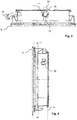
- eine vertikale Ansicht einer Manschette für eine Wäschebehandlungsmaschine, in welcher eine Düse angebracht ist;
- Fig. 3
- eine Ansicht der Manschette in
Fig. 2 senkrecht zur dortigen Linie A-A; - Fig. 4
- eine Ansicht der Manschette in
Fig. 2 senkrecht zur dortigen Linie B-B; - Fig. 5
- eine Ansicht der Manschette in
Fig. 4 senkrecht zur dortigen Linie C-C; - Fig. 6
- eine Vergrößerung des Kreises D in
Fig. 5 ; und - Fig. 7
- eine schematische Teilansicht einer Düse.
-
Figur 1 zeigt einen horizontalen Schnitt durch eine Wäschebehandlungsmaschine 1, welche eine in einem schwingend aufgehängten Laugenbehälter 2 befindliche drehbare Trommel 3 aufweist und durch eine in einer im Wesentlichen vertikal ausgerichteten Frontseite 4 befindliche und dicht verschließbare Tür 5 mit Wäsche beschickbar ist. Die Lage der Frontseite 4 ist inFig. 1 nur schematisch durch eine gestrichelte Linie angedeutet. Von der Tür 5 ist inFig. 1 der Übersicht halber nur ein Schauglas dargestellt; von der Darstellung weiterer Komponenten ist der Übersicht halber abgesehen worden. Die Tür 5 ist, wenn sie wie inFig. 1 geschlossen ist, mittels einer aus einem elastisch verformbaren Werkstoff bestehende Manschette 6 gegen die Frontseite 4 und den Laugenbehälter 2 abgedichtet. Die Manschette 6 muss beweglich sein, denn sie muss Bewegungen des Laugenbehälters 2, die dieser trotz einer (nicht dargestellten) dämpfenden Aufhängung im Gehäuse der Wäschebehandlungsmaschine 1 beim Rotieren der Trommel 3 mit eingefüllter Wäsche vollführt, mittvollziehen und dabei den Laugenbehälter 2 gegen die Tür 5 dauerhaft abdichten. - Eine Mittelachse 7 definiert sowohl die räumliche Mitte der Tür 5 bzw. deren Schauglases und der Manschette 6 als auch die Rotationsachse der Trommel 3, welche drehbar im Laugenbehälter 2 angebracht und mittels eines Trommellagers 8 fliegend gelagert ist. Durch das Trommellager 8 hindurch wird die Trommel 3 mittels eines nicht dargestellten Motors zur Rotation angetrieben. In der Trommel 3 sind Mitnehmer 9 angebracht, welche dazu dienen, in der Trommel 3 befindliche Wäschestücke in einem Wasch- oder Spülprozess während der Rotation der Trommel 3 hochzuheben und zu durchmischen, um sie mechanisch zu bearbeiten. Die Mitnehmer 9 können auch dazu dienen, Lauge aus dem Laugenbehälter 2 zu schöpfen und diese auf die Wäsche herabfließen zu lassen.
- Die auf
Figur 1 folgenden Figuren der Zeichnung zeigen, wie die Manschette 6 mit Mitteln versehen ist, um - ggf. zusätzlich zu der Schöpffunktion der Mitnehmer 9 - eine intensive Umwälzung von Wasch- oder Spüllauge (nachfolgend gemeinsam als "Lauge" oder "Flüssigkeit" bezeichnet) im Laugenbehälter 2 zu erreichen und die zu behandelnde Wäsche intensiv mit solcher Wasch- oder Spüllauge zu benetzen. -
Figur 2 zeigt eine vertikale Ansicht der Manschette 6 für die Wäschebehandlungsmaschine 1 derFigur 1 . In dieser im Wesentlichen kreisrunden Manschette 6 ist zunächst ein Zulauf 10 angebracht, durch welchen mittels einer entsprechenden, nicht dargestellten Zuführeinrichtung frische Lauge bzw. frisches Wasser in den Laugenbehälter 2 eingebracht werden kann. Auch ist ein Ablauf 11 vorhanden, durch welchen Lauge, die sich in den Falten der Manschette 6 gesammelt hat, ablaufen kann, wobei dies vorzugsweise in den Laugenbehälter 2 zurück erfolgt. Außerdem ist eine Düse 12 vorhanden, welche vorgesehen ist, um Flüssigkeit in dem Laugenbehälter 2 während eines Wäschebehandlungsprozesses intensiv umzuwälzen. Dazu ist eine Fördereinrichtung 14 vorgesehen, welche Flüssigkeit aus dem Laugenbehälter 2 herauspumpt und der Düse 12 zum Einführen eines Strahls von Flüssigkeit in die Trommel 3 zuführt. Diese Düse 12 ist an der Manschette 6 angeordnet und ist aus einem elastisch verformbaren Werkstoff gebildet. Sie weist eine anhand der folgenden Figuren näher zu beschreibende spezifisch geformte Austrittsfläche 23 auf, welche entlang einer Längsachse 22 gestreckt und mehrfach konkav ist. Die Düse 12 ragt auch offen aus der Manschette 6 hinaus. Dies dient insbesondere dazu, der Düse eine Verformung zu gestatten, wenn mit der umzuwälzenden Flüssigkeit ein Fremdkörper, zum Beispiel ein Konglomerat aus Schmutzpartikeln und Flusen, durch die Fördereinrichtung 14 in die Düse 12 gelangt. Durch die Verformung kann die Düse 12 einem solchen Fremdkörper die Passage ermöglichen, wodurch einer Verstopfung der Düse 12 wirksam vorgebeugt ist. - Die Düse 12 ist in einer zur Mittelachse 7 senkrechten Vertikalebene und oberhalb einer in der Vertikalebene liegenden und die Mittelachse 7 schneidenden Horizontalachse 16, welche in
Fig. 2 auch die Vertikalebene repräsentiert, angeordnet. Dabei schließt eine von der Mittelachse 7 ausgehende, in der Vertikalebene liegende und zur Düse 12 führende Positionslinie 17 mit der Horizontalachse 16 einen ersten Winkel 18 ein, welcher zwischen 30° und 60° liegen kann und gemäßFig. 2 etwa 45° beträgt. - Aus
Fig. 3 und Fig. 4 erweist sich, dass die Düse 12 eine spezifische Ausrichtung hat und demgemäß bezüglich der Horizontalen als auch bezüglich der Vertikalen gekippt und gedreht ist. Dies dient dem Zweck, dass der durch die Fördereinrichtung und die Düse gebildete Strahl die Wäsche in der Trommel möglichst gleichmäßig benetzt. Dazu kommt es auch auf die Auslegung der Fördereinrichtung 14 an, insbesondere darauf, welche Menge an Flüssigkeit diese fördern und bei welchem Druck sie diese der Düse 12 zustellen kann. Entsprechende Konstruktions- und Betriebsparameter für die Fördereinrichtung 14 sind deshalb im Rahmen gewöhnlicher Praxis zu wählen. Insbesondere ist die Düse 12 derart ausgerichtet, dass der durch die Fördereinrichtung 14 gebildete Strahl die Trommel 3 mittig durchquert und die Wäsche in der Trommel 3 gleichmäßig benetzt. Dementsprechend schließt die Längsachse 22 der Düse mit der Vertikalebene einen zweiten Winkel 20 ein, welcher zwischen 15° und 30° liegen kann und gemäßFig. 3 und Fig. 4 etwa 22° beträgt. - Gemäß den
Figuren 5 und 6 , wobeiFig. 6 einen Teil derFig. 5 vergrößert darstellt, ist die Düse 12 über einen Düsenhalter 13 mit der Fördereinrichtung 14 verbunden, wobei der Düsenhalter 13 die Manschette 6 durchquert und die Düse 12 mit der Fördereinrichtung 14 verbindet. Die Düse 12 weist entlang ihrer Längsachse 22 beidseitig jeweils eine Stützrippe 21 auf, wobei die Stützrippen 21 die Düse 12 gegen den Düsenhalter 13 abstützen. Die entlang der Längsachse gestreckte Form der Düse 12 bestimmt und wahrt deren Verformbarkeit, um gegebenenfalls Konglomerate aus Schmutzteilchen und/oder Flusen passieren zu lassen, auch in Gegenwart der Stützrippen 21. Ein Vorteil der Stützrippen liegt darin, dass sie die Düse 12 gegen den Düsenhalter 13 abstützen und somit die Ausrichtung der Düse 12 zur Bildung besagten Strahls zu gewährleisten. - Der Düsenhalter 13 fluchtet innenseitig mit der Manschette 6, wie am besten aus
Fig. 6 zu erkennen. Damit sind Stufen und Einsenkungen der Oberfläche in der Nähe der Düse 12 vermieden, was im Hinblick auf die Vermeidung von Ablagerungen von Flusen oder Schmutzpartikeln in der Nähe der Düse 12 sinnvoll und vorteilhaft ist. - Die Austrittsfläche 23 der Düse 12 ist bezüglich der Längsachse 22 symmetrisch, speziell spiegelsymmetrisch, und weist beidseitig der Längsachse 22 mehrere, speziell vier, Einbuchtungen auf. Die Austrittsfläche 23 hat eine Umfangslinie, welche aus Kreisbögen gebildet ist. Dabei liegen sich die Einbuchtungen entlang der Längsachse 22 einander paarweise gegenüber, und die Austrittsfläche 23 wird dadurch senkrecht zur Längsachse 22 bis auf 50% ihrer maximalen Breite senkrecht zur Längsachse 22 verengt. Diese Ausgestaltung hat sich für den bestimmungsgemäßen Betrieb der Düse 12 als besonders geeignet erwiesen.
-
Fig. 7 zeigt eine vereinfachte Teilansicht der Düse 12, aus welcher auch einige bereits erwähnte Details besonders genau hervorgehen.Fig. 7 zeigt auch, wie die Düse 12 in Bezug auf ihre lokale Vertikale, welche durch die Positionslinie 17 definiert ist, gekippt ist. Dazu bestimmt die Austrittsfläche 23 eine Austrittsebene, welche mit der Positionslinie 17 einen dritten Winkel 26 einschließt der zwischen 20° und 40° betragen kann und vorliegend etwa 28° beträgt. - Der Werkstoff, aus dem die Düse 12 besteht, ist derselbe wie der Werkstoff, aus dem die Manschette 6 besteht. Dazu kommen besonders in Betracht Werkstoffe wie synthetischer Kautschuk, insbesondere EPDM, und thermoplastische Elastomere (TPE), wobei bei der Auswahl letzterer darauf zu achten ist, dass die Werkstoffe bei den in der Wäschebehandlungsmaschine 1 denkbaren Temperaturen, also 0°C bis 100°C, und Umgebungsbedingungen, welche insbesondere durch die Anwesenheit stark alkalischer Waschlaugen bestimmt sind, ausreichend inert sind. Speziell kommen Werkstoffe in Betracht, deren Härte Shore A zwischen 35 und 50, insbesondere zwischen 35 und 41 oder zwischen 42 und 48, beträgt.
- Gemäß der Erfindung besteht die Düse 12 aus einem elastisch verformbaren Werkstoff einerseits und hat eine durch ihre Austrittsfläche 23 bestimmte Form, welche aufgrund deren relativ großen Umfangs eine elastische Verformung begünstigt, wenn sich in an oder in der Nähe der Austrittsfläche 23 ein Konglomerat aus Schmutzteilchen und/oder Flusen ablagern sollte und sich damit beim Umwälzen von Flüssigkeit ein erhöhtes Druckgefälle über der Düse 12 einstellt. Diese Düse 12 kann sich dabei so verformen, dass das Konglomerat durch die Austrittsfläche 23 austreten kann. Somit ist einer Verstopfung der Düse effektiv vorgebeugt. Somit ist ein Strahl von umgewälzter Flüssigkeit realisierbar, welcher tief in die Trommel mit der zu behandelnden Wäsche hinein gelangt und ein gleichmäßig intensives Benetzen der Wäsche sicherstellt.
-
- 1
- Wäschebehandlungsmaschine
- 2
- Laugenbehälter
- 3
- Trommel
- 4
- Frontseite
- 5
- Tür
- 6
- Manschette
- 7
- Mittelachse
- 8
- Trommellager
- 9
- Mitnehmer
- 10
- Zulauf
- 11
- Ablauf
- 12
- Düse
- 13
- Düsenhalter
- 14
- Fördereinrichtung
- 15
- Wäscheabweiser
- 16
- Horizontalachse
- 17
- Positionslinie
- 18
- Erster Winkel
- 19
- Senkrechte auf die Austrittsfläche
- 20
- Zweiter Winkel
- 21
- Stützrippe
- 22
- Längsachse
- 23
- Austrittsfläche
- 24
- Eintrittsfläche
- 25
- Mittelachsenparallele
- 26
- Dritter Winkel
Claims (15)
- Wäschebehandlungsmaschine (1), welche eine in einem schwingend aufgehängten Laugenbehälter (2) befindliche drehbare Trommel (3) aufweist und durch eine in einer im Wesentlichen vertikal ausgerichteten Frontseite (4) befindliche und dicht verschließbare Tür (5) mit Wäsche beschickbar ist, wobei die Tür (5) mittels einer aus einem elastisch verformbaren Werkstoff bestehende Manschette (6) gegen die Frontseite (4) und den Laugenbehälter (2) abgedichtet ist, und welche eine Fördereinrichtung (14) und eine Düse (12) zum Einführen eines Strahls von Flüssigkeit in die Trommel (3) aufweist, wobei die Düse (12) an der Manschette (6) angeordnet ist, dadurch gekennzeichnet, dass die Düse (12) aus einem elastisch verformbaren Werkstoff gebildet ist und eine Austrittsfläche (23) aufweist, welche entlang einer Längsachse (22) gestreckt und mehrfach konkav ist.
- Wäschebehandlungsmaschine (1) nach Anspruch 1, bei der die Austrittsfläche (23) bezüglich der Längsachse (22) symmetrisch ist und beidseitig der Längsachse (22) mehrere Einbuchtungen aufweist.
- Wäschebehandlungsmaschine (1) nach Anspruch 2, bei der die Austrittsfläche (23) eine Umfangslinie aufweist, welche aus Kreisbögen gebildet ist.
- Wäschebehandlungsmaschine (1) nach einem der Ansprüche 2 und 3, bei der die Einbuchtungen entlang der Längsachse (22) paarweise einander gegenüberliegen und die Austrittsfläche (23) senkrecht zur Längsachse (22) bis auf 50% ihrer maximalen Breite senkrecht zur Längsachse (22) verengen.
- Wäschebehandlungsmaschine (1) nach einem der vorigen Ansprüche, bei der die Düse (12) offen aus der Manschette (6) hinausragt.
- Wäschebehandlungsmaschine (1) nach Anspruch 5, bei der die Düse (12) über einen Düsenhalter (13) mit der Fördereinrichtung (14) verbunden ist, wobei der Düsenhalter (13) die Manschette (6) durchquert und die Düse (12) mit der Fördereinrichtung (14) verbindet, und wobei die Düse (12) entlang der Längsachse (22) beidseitig jeweils eine Stützrippe (21) aufweist, welche Stützrippen (21) die Düse (12) gegen den Düsenhalter (13) abstützen.
- Wäschebehandlungsmaschine (1) nah Anspruch 6, bei der der Düsenhalter (13) innenseitig mit der Manschette (6) fluchtet.
- Wäschebehandlungsmaschine (1) nach einem der vorhergehenden Ansprüche, bei der die Manschette (6) im Wesentlichen kreisrund ist, die Manschette (6) eine Mittelachse (7) aufweist und bei der die Düse (12) in einer zur Mittelachse (7) senkrechten Vertikalebene und oberhalb einer in der Vertikalebene liegenden und die Mittelachse (7) schneidenden Horizontalachse (16) angeordnet ist.
- Wäschebehandlungsmaschine (1) nach Anspruch 8, bei der eine von der Mittelachse (7) ausgehende, in der Vertikalebene liegende und zur Düse (12) führende Positionslinie (17) mit der Horizontalachse (16) einen ersten Winkel (18) zwischen 30° und 60°, insbesondere von etwa 45°, einschließt.
- Wäschebehandlungsmaschine (1) nach Anspruch 9, bei der die Austrittsfläche (23) eine Austrittsebene bestimmt, welche mit der Positionslinie (17) einen dritten Winkel (26) zwischen 20° und 40°, insbesondere etwa 28°, einschließt.
- Wäschebehandlungsmaschine (1) nach einem der Ansprüche 8 bis 10, bei der die Längsachse (22) mit der Vertikalebene einen zweiten Winkel (20) zwischen 15° und 30°, insbesondere von etwa 22°, einschließt.
- Wäschebehandlungsmaschine (1) nach einem der vorigen Ansprüche, bei der die Düse (12) derart ausgerichtet ist, dass der durch die Fördereinrichtung (14) gebildete Strahl die Trommel (3) mittig durchquert.
- Wäschebehandlungsmaschine (1) nach einem der vorigen Ansprüche, bei der der Werkstoff, aus dem die Düse (12) besteht, derselbe ist wie der Werkstoff, aus dem die Manschette (6) besteht.
- Wäschebehandlungsmaschine (1) nach Anspruch 15, bei der der Werkstoff ein synthetischer Kautschuk, insb. EPDM, oder ein thermoplastisches Elastomer (TPE) ist.
- Wäschebehandlungsmaschine (1) nach einem der Ansprüche 15 und 16, bei der der Werkstoff eine Härte Shore A zwischen 35 und 50, insbesondere zwischen 35 und 41 oder zwischen 42 und 48, aufweist.
Applications Claiming Priority (1)
| Application Number | Priority Date | Filing Date | Title |
|---|---|---|---|
| DE102020206472.5A DE102020206472A1 (de) | 2020-05-25 | 2020-05-25 | Wäschebehandlungsmaschine mit einer düse zum einführen eines strahls von flüssigkeit |
Publications (2)
| Publication Number | Publication Date |
|---|---|
| EP3916144A1 true EP3916144A1 (de) | 2021-12-01 |
| EP3916144B1 EP3916144B1 (de) | 2023-10-18 |
Family
ID=75746396
Family Applications (1)
| Application Number | Title | Priority Date | Filing Date |
|---|---|---|---|
| EP21171437.3A Active EP3916144B1 (de) | 2020-05-25 | 2021-04-30 | Wäschebehandlungsmaschine mit einer düse zum einführen eines strahls von flüssigkeit |
Country Status (3)
| Country | Link |
|---|---|
| EP (1) | EP3916144B1 (de) |
| CN (1) | CN113718490B (de) |
| DE (1) | DE102020206472A1 (de) |
Families Citing this family (1)
| Publication number | Priority date | Publication date | Assignee | Title |
|---|---|---|---|---|
| DE102022212508A1 (de) * | 2022-11-23 | 2024-05-23 | BSH Hausgeräte GmbH | Wäschepflegegerät mit einer Steuerung |
Citations (7)
| Publication number | Priority date | Publication date | Assignee | Title |
|---|---|---|---|---|
| DE3738388A1 (de) * | 1987-11-12 | 1989-05-24 | Bauknecht Hausgeraete | Waschmaschine |
| DE4330079A1 (de) | 1993-09-06 | 1995-03-09 | Bosch Siemens Hausgeraete | Frontseitig beschickbare Trommelwaschmaschine |
| EP1505191A1 (de) | 2003-08-07 | 2005-02-09 | Lg Electronics Inc. | Waschmaschine |
| WO2006027149A1 (de) * | 2004-09-07 | 2006-03-16 | Miele & Cie. Kg | Frontbeschickbare trommelwaschmaschine mit wäscheabweiser an der faltenbalgdichtung |
| DE102005055777B3 (de) * | 2005-11-21 | 2006-11-16 | Miele & Cie. Kg | Stirnseitig beschickbare Wäschebehandlungsmaschine, wie Waschmaschine oder Waschtrockner |
| US20110083477A1 (en) * | 2009-10-13 | 2011-04-14 | Wooyoung Kim | Laundry treating apparatus |
| WO2019161898A1 (en) * | 2018-02-22 | 2019-08-29 | Electrolux Appliances Aktiebolag | Laundry washing machine equipped with a liquid supply line |
Family Cites Families (6)
| Publication number | Priority date | Publication date | Assignee | Title |
|---|---|---|---|---|
| CN1521340A (zh) * | 2003-02-13 | 2004-08-18 | 乐金电子(天津)电器有限公司 | 滚桶洗衣机防止泡沫溢出装置 |
| JP4704187B2 (ja) * | 2005-10-28 | 2011-06-15 | 日立アプライアンス株式会社 | 洗濯乾燥機 |
| CN2926285Y (zh) * | 2005-12-27 | 2007-07-25 | 苏州三星电子有限公司 | 门缝进水滚筒洗衣机 |
| JP5446901B2 (ja) * | 2010-01-15 | 2014-03-19 | パナソニック株式会社 | ドラム式洗濯乾燥機 |
| DE102018214137A1 (de) | 2018-08-22 | 2020-02-27 | BSH Hausgeräte GmbH | Wäschepflegegerät mit einer Einlassdüse |
| CN209741476U (zh) * | 2019-01-30 | 2019-12-06 | 青岛海尔滚筒洗衣机有限公司 | 滚筒洗衣机 |
-
2020
- 2020-05-25 DE DE102020206472.5A patent/DE102020206472A1/de not_active Withdrawn
-
2021
- 2021-04-30 EP EP21171437.3A patent/EP3916144B1/de active Active
- 2021-05-20 CN CN202110550012.1A patent/CN113718490B/zh active Active
Patent Citations (7)
| Publication number | Priority date | Publication date | Assignee | Title |
|---|---|---|---|---|
| DE3738388A1 (de) * | 1987-11-12 | 1989-05-24 | Bauknecht Hausgeraete | Waschmaschine |
| DE4330079A1 (de) | 1993-09-06 | 1995-03-09 | Bosch Siemens Hausgeraete | Frontseitig beschickbare Trommelwaschmaschine |
| EP1505191A1 (de) | 2003-08-07 | 2005-02-09 | Lg Electronics Inc. | Waschmaschine |
| WO2006027149A1 (de) * | 2004-09-07 | 2006-03-16 | Miele & Cie. Kg | Frontbeschickbare trommelwaschmaschine mit wäscheabweiser an der faltenbalgdichtung |
| DE102005055777B3 (de) * | 2005-11-21 | 2006-11-16 | Miele & Cie. Kg | Stirnseitig beschickbare Wäschebehandlungsmaschine, wie Waschmaschine oder Waschtrockner |
| US20110083477A1 (en) * | 2009-10-13 | 2011-04-14 | Wooyoung Kim | Laundry treating apparatus |
| WO2019161898A1 (en) * | 2018-02-22 | 2019-08-29 | Electrolux Appliances Aktiebolag | Laundry washing machine equipped with a liquid supply line |
Also Published As
| Publication number | Publication date |
|---|---|
| EP3916144B1 (de) | 2023-10-18 |
| DE102020206472A1 (de) | 2021-11-25 |
| CN113718490A (zh) | 2021-11-30 |
| CN113718490B (zh) | 2026-05-01 |
Similar Documents
| Publication | Publication Date | Title |
|---|---|---|
| DE60317274T2 (de) | Waschmaschine | |
| DE10227863B4 (de) | Trommelwaschmaschine | |
| DE69618826T2 (de) | Düsenfärbeapparat und düsenfärbeverfahren | |
| DE10349374B4 (de) | Nassbehandlungsmaschine für strangförmiges Textilgut | |
| DE102010042514A1 (de) | Verfahren zum Steuern einer Waschmaschine | |
| EP3916144B1 (de) | Wäschebehandlungsmaschine mit einer düse zum einführen eines strahls von flüssigkeit | |
| DE112018001841B4 (de) | Waschmaschine | |
| EP1700943B1 (de) | Waschmaschine mit Einspritzdüse | |
| EP2022882A2 (de) | Trommel für eine Waschmaschine und Waschmaschine | |
| WO2008000591A1 (de) | Verfahren zum einbringen von waschmitteln und waschmaschine dafür | |
| DE102008054392A1 (de) | Mitnehmer, Wäschetrommel und Waschmaschine | |
| EP2348152A1 (de) | Waschmaschine mit Umfluteinrichtung | |
| DE734205C (de) | Schleudermaschine | |
| DE102018214137A1 (de) | Wäschepflegegerät mit einer Einlassdüse | |
| DE2903125A1 (de) | Vorrichtung zum kontinuierlichen nassbehandeln von fluessigkeitsdurchlaessigem textilgut o.dgl. | |
| DE3506948C2 (de) | Verfahren zum Abziehen von Flusen bei einer Textilwaschmaschine und Textilwaschmaschine | |
| DE19500370A1 (de) | Programmgesteuerte Waschmaschine | |
| DE4210782A1 (de) | Programmgesteuerte Trommelwaschmaschine | |
| EP4180565A1 (de) | Einspülsystem, wasserführendes haushaltsgerät und verfahren zum leiten von fluid | |
| DE102013106097B4 (de) | Verfahren zum Betreiben einer Waschmaschine und Waschmaschine | |
| CH712014B1 (de) | Waschmaschine mit Wasserzufuhr durch die Trommelrückseite. | |
| DE3633441A1 (de) | Verfahren und einrichtung zum nasswaschen von kleidungsstuecken | |
| DE102022207454B3 (de) | Waschmaschine und Verfahren zum Betrieb einer Waschmaschine | |
| EP2821539A1 (de) | Trommelwaschmaschine mit Unwuchtausgleich und Umflutung | |
| BE1029571B1 (de) | Trommel für eine Waschmaschine und Waschmaschine |
Legal Events
| Date | Code | Title | Description |
|---|---|---|---|
| PUAI | Public reference made under article 153(3) epc to a published international application that has entered the european phase |
Free format text: ORIGINAL CODE: 0009012 |
|
| STAA | Information on the status of an ep patent application or granted ep patent |
Free format text: STATUS: THE APPLICATION HAS BEEN PUBLISHED |
|
| AK | Designated contracting states |
Kind code of ref document: A1 Designated state(s): AL AT BE BG CH CY CZ DE DK EE ES FI FR GB GR HR HU IE IS IT LI LT LU LV MC MK MT NL NO PL PT RO RS SE SI SK SM TR |
|
| B565 | Issuance of search results under rule 164(2) epc |
Effective date: 20211005 |
|
| STAA | Information on the status of an ep patent application or granted ep patent |
Free format text: STATUS: REQUEST FOR EXAMINATION WAS MADE |
|
| 17P | Request for examination filed |
Effective date: 20220601 |
|
| RBV | Designated contracting states (corrected) |
Designated state(s): AL AT BE BG CH CY CZ DE DK EE ES FI FR GB GR HR HU IE IS IT LI LT LU LV MC MK MT NL NO PL PT RO RS SE SI SK SM TR |
|
| GRAP | Despatch of communication of intention to grant a patent |
Free format text: ORIGINAL CODE: EPIDOSNIGR1 |
|
| STAA | Information on the status of an ep patent application or granted ep patent |
Free format text: STATUS: GRANT OF PATENT IS INTENDED |
|
| INTG | Intention to grant announced |
Effective date: 20230601 |
|
| GRAS | Grant fee paid |
Free format text: ORIGINAL CODE: EPIDOSNIGR3 |
|
| GRAA | (expected) grant |
Free format text: ORIGINAL CODE: 0009210 |
|
| STAA | Information on the status of an ep patent application or granted ep patent |
Free format text: STATUS: THE PATENT HAS BEEN GRANTED |
|
| AK | Designated contracting states |
Kind code of ref document: B1 Designated state(s): AL AT BE BG CH CY CZ DE DK EE ES FI FR GB GR HR HU IE IS IT LI LT LU LV MC MK MT NL NO PL PT RO RS SE SI SK SM TR |
|
| REG | Reference to a national code |
Ref country code: GB Ref legal event code: FG4D Free format text: NOT ENGLISH |
|
| REG | Reference to a national code |
Ref country code: CH Ref legal event code: EP |
|
| REG | Reference to a national code |
Ref country code: IE Ref legal event code: FG4D Free format text: LANGUAGE OF EP DOCUMENT: GERMAN |
|
| REG | Reference to a national code |
Ref country code: DE Ref legal event code: R096 Ref document number: 502021001719 Country of ref document: DE |
|
| REG | Reference to a national code |
Ref country code: LT Ref legal event code: MG9D |
|
| REG | Reference to a national code |
Ref country code: NL Ref legal event code: MP Effective date: 20231018 |
|
| PG25 | Lapsed in a contracting state [announced via postgrant information from national office to epo] |
Ref country code: NL Free format text: LAPSE BECAUSE OF FAILURE TO SUBMIT A TRANSLATION OF THE DESCRIPTION OR TO PAY THE FEE WITHIN THE PRESCRIBED TIME-LIMIT Effective date: 20231018 |
|
| PG25 | Lapsed in a contracting state [announced via postgrant information from national office to epo] |
Ref country code: GR Free format text: LAPSE BECAUSE OF FAILURE TO SUBMIT A TRANSLATION OF THE DESCRIPTION OR TO PAY THE FEE WITHIN THE PRESCRIBED TIME-LIMIT Effective date: 20240119 |
|
| PG25 | Lapsed in a contracting state [announced via postgrant information from national office to epo] |
Ref country code: IS Free format text: LAPSE BECAUSE OF FAILURE TO SUBMIT A TRANSLATION OF THE DESCRIPTION OR TO PAY THE FEE WITHIN THE PRESCRIBED TIME-LIMIT Effective date: 20240218 |
|
| PG25 | Lapsed in a contracting state [announced via postgrant information from national office to epo] |
Ref country code: LT Free format text: LAPSE BECAUSE OF FAILURE TO SUBMIT A TRANSLATION OF THE DESCRIPTION OR TO PAY THE FEE WITHIN THE PRESCRIBED TIME-LIMIT Effective date: 20231018 |
|
| PG25 | Lapsed in a contracting state [announced via postgrant information from national office to epo] |
Ref country code: ES Free format text: LAPSE BECAUSE OF FAILURE TO SUBMIT A TRANSLATION OF THE DESCRIPTION OR TO PAY THE FEE WITHIN THE PRESCRIBED TIME-LIMIT Effective date: 20231018 |
|
| PG25 | Lapsed in a contracting state [announced via postgrant information from national office to epo] |
Ref country code: LT Free format text: LAPSE BECAUSE OF FAILURE TO SUBMIT A TRANSLATION OF THE DESCRIPTION OR TO PAY THE FEE WITHIN THE PRESCRIBED TIME-LIMIT Effective date: 20231018 Ref country code: IS Free format text: LAPSE BECAUSE OF FAILURE TO SUBMIT A TRANSLATION OF THE DESCRIPTION OR TO PAY THE FEE WITHIN THE PRESCRIBED TIME-LIMIT Effective date: 20240218 Ref country code: GR Free format text: LAPSE BECAUSE OF FAILURE TO SUBMIT A TRANSLATION OF THE DESCRIPTION OR TO PAY THE FEE WITHIN THE PRESCRIBED TIME-LIMIT Effective date: 20240119 Ref country code: ES Free format text: LAPSE BECAUSE OF FAILURE TO SUBMIT A TRANSLATION OF THE DESCRIPTION OR TO PAY THE FEE WITHIN THE PRESCRIBED TIME-LIMIT Effective date: 20231018 Ref country code: BG Free format text: LAPSE BECAUSE OF FAILURE TO SUBMIT A TRANSLATION OF THE DESCRIPTION OR TO PAY THE FEE WITHIN THE PRESCRIBED TIME-LIMIT Effective date: 20240118 Ref country code: PT Free format text: LAPSE BECAUSE OF FAILURE TO SUBMIT A TRANSLATION OF THE DESCRIPTION OR TO PAY THE FEE WITHIN THE PRESCRIBED TIME-LIMIT Effective date: 20240219 |
|
| PG25 | Lapsed in a contracting state [announced via postgrant information from national office to epo] |
Ref country code: SE Free format text: LAPSE BECAUSE OF FAILURE TO SUBMIT A TRANSLATION OF THE DESCRIPTION OR TO PAY THE FEE WITHIN THE PRESCRIBED TIME-LIMIT Effective date: 20231018 Ref country code: RS Free format text: LAPSE BECAUSE OF FAILURE TO SUBMIT A TRANSLATION OF THE DESCRIPTION OR TO PAY THE FEE WITHIN THE PRESCRIBED TIME-LIMIT Effective date: 20231018 Ref country code: PL Free format text: LAPSE BECAUSE OF FAILURE TO SUBMIT A TRANSLATION OF THE DESCRIPTION OR TO PAY THE FEE WITHIN THE PRESCRIBED TIME-LIMIT Effective date: 20231018 Ref country code: NO Free format text: LAPSE BECAUSE OF FAILURE TO SUBMIT A TRANSLATION OF THE DESCRIPTION OR TO PAY THE FEE WITHIN THE PRESCRIBED TIME-LIMIT Effective date: 20240118 Ref country code: LV Free format text: LAPSE BECAUSE OF FAILURE TO SUBMIT A TRANSLATION OF THE DESCRIPTION OR TO PAY THE FEE WITHIN THE PRESCRIBED TIME-LIMIT Effective date: 20231018 Ref country code: HR Free format text: LAPSE BECAUSE OF FAILURE TO SUBMIT A TRANSLATION OF THE DESCRIPTION OR TO PAY THE FEE WITHIN THE PRESCRIBED TIME-LIMIT Effective date: 20231018 |
|
| PG25 | Lapsed in a contracting state [announced via postgrant information from national office to epo] |
Ref country code: DK Free format text: LAPSE BECAUSE OF FAILURE TO SUBMIT A TRANSLATION OF THE DESCRIPTION OR TO PAY THE FEE WITHIN THE PRESCRIBED TIME-LIMIT Effective date: 20231018 |
|
| REG | Reference to a national code |
Ref country code: DE Ref legal event code: R097 Ref document number: 502021001719 Country of ref document: DE |
|
| PG25 | Lapsed in a contracting state [announced via postgrant information from national office to epo] |
Ref country code: CZ Free format text: LAPSE BECAUSE OF FAILURE TO SUBMIT A TRANSLATION OF THE DESCRIPTION OR TO PAY THE FEE WITHIN THE PRESCRIBED TIME-LIMIT Effective date: 20231018 |
|
| PG25 | Lapsed in a contracting state [announced via postgrant information from national office to epo] |
Ref country code: SK Free format text: LAPSE BECAUSE OF FAILURE TO SUBMIT A TRANSLATION OF THE DESCRIPTION OR TO PAY THE FEE WITHIN THE PRESCRIBED TIME-LIMIT Effective date: 20231018 |
|
| PG25 | Lapsed in a contracting state [announced via postgrant information from national office to epo] |
Ref country code: SM Free format text: LAPSE BECAUSE OF FAILURE TO SUBMIT A TRANSLATION OF THE DESCRIPTION OR TO PAY THE FEE WITHIN THE PRESCRIBED TIME-LIMIT Effective date: 20231018 Ref country code: SK Free format text: LAPSE BECAUSE OF FAILURE TO SUBMIT A TRANSLATION OF THE DESCRIPTION OR TO PAY THE FEE WITHIN THE PRESCRIBED TIME-LIMIT Effective date: 20231018 Ref country code: RO Free format text: LAPSE BECAUSE OF FAILURE TO SUBMIT A TRANSLATION OF THE DESCRIPTION OR TO PAY THE FEE WITHIN THE PRESCRIBED TIME-LIMIT Effective date: 20231018 Ref country code: IT Free format text: LAPSE BECAUSE OF FAILURE TO SUBMIT A TRANSLATION OF THE DESCRIPTION OR TO PAY THE FEE WITHIN THE PRESCRIBED TIME-LIMIT Effective date: 20231018 Ref country code: EE Free format text: LAPSE BECAUSE OF FAILURE TO SUBMIT A TRANSLATION OF THE DESCRIPTION OR TO PAY THE FEE WITHIN THE PRESCRIBED TIME-LIMIT Effective date: 20231018 Ref country code: DK Free format text: LAPSE BECAUSE OF FAILURE TO SUBMIT A TRANSLATION OF THE DESCRIPTION OR TO PAY THE FEE WITHIN THE PRESCRIBED TIME-LIMIT Effective date: 20231018 Ref country code: CZ Free format text: LAPSE BECAUSE OF FAILURE TO SUBMIT A TRANSLATION OF THE DESCRIPTION OR TO PAY THE FEE WITHIN THE PRESCRIBED TIME-LIMIT Effective date: 20231018 |
|
| PLBE | No opposition filed within time limit |
Free format text: ORIGINAL CODE: 0009261 |
|
| STAA | Information on the status of an ep patent application or granted ep patent |
Free format text: STATUS: NO OPPOSITION FILED WITHIN TIME LIMIT |
|
| 26N | No opposition filed |
Effective date: 20240719 |
|
| PG25 | Lapsed in a contracting state [announced via postgrant information from national office to epo] |
Ref country code: SI Free format text: LAPSE BECAUSE OF FAILURE TO SUBMIT A TRANSLATION OF THE DESCRIPTION OR TO PAY THE FEE WITHIN THE PRESCRIBED TIME-LIMIT Effective date: 20231018 |
|
| PG25 | Lapsed in a contracting state [announced via postgrant information from national office to epo] |
Ref country code: SI Free format text: LAPSE BECAUSE OF FAILURE TO SUBMIT A TRANSLATION OF THE DESCRIPTION OR TO PAY THE FEE WITHIN THE PRESCRIBED TIME-LIMIT Effective date: 20231018 |
|
| PG25 | Lapsed in a contracting state [announced via postgrant information from national office to epo] |
Ref country code: MC Free format text: LAPSE BECAUSE OF FAILURE TO SUBMIT A TRANSLATION OF THE DESCRIPTION OR TO PAY THE FEE WITHIN THE PRESCRIBED TIME-LIMIT Effective date: 20231018 |
|
| PG25 | Lapsed in a contracting state [announced via postgrant information from national office to epo] |
Ref country code: MC Free format text: LAPSE BECAUSE OF FAILURE TO SUBMIT A TRANSLATION OF THE DESCRIPTION OR TO PAY THE FEE WITHIN THE PRESCRIBED TIME-LIMIT Effective date: 20231018 |
|
| REG | Reference to a national code |
Ref country code: CH Ref legal event code: PL |
|
| PG25 | Lapsed in a contracting state [announced via postgrant information from national office to epo] |
Ref country code: LU Free format text: LAPSE BECAUSE OF NON-PAYMENT OF DUE FEES Effective date: 20240430 |
|
| REG | Reference to a national code |
Ref country code: BE Ref legal event code: MM Effective date: 20240430 |
|
| PG25 | Lapsed in a contracting state [announced via postgrant information from national office to epo] |
Ref country code: LU Free format text: LAPSE BECAUSE OF NON-PAYMENT OF DUE FEES Effective date: 20240430 |
|
| PG25 | Lapsed in a contracting state [announced via postgrant information from national office to epo] |
Ref country code: BE Free format text: LAPSE BECAUSE OF NON-PAYMENT OF DUE FEES Effective date: 20240430 |
|
| PG25 | Lapsed in a contracting state [announced via postgrant information from national office to epo] |
Ref country code: FR Free format text: LAPSE BECAUSE OF NON-PAYMENT OF DUE FEES Effective date: 20240430 |
|
| PG25 | Lapsed in a contracting state [announced via postgrant information from national office to epo] |
Ref country code: FR Free format text: LAPSE BECAUSE OF NON-PAYMENT OF DUE FEES Effective date: 20240430 Ref country code: BE Free format text: LAPSE BECAUSE OF NON-PAYMENT OF DUE FEES Effective date: 20240430 Ref country code: CH Free format text: LAPSE BECAUSE OF NON-PAYMENT OF DUE FEES Effective date: 20240430 |
|
| PG25 | Lapsed in a contracting state [announced via postgrant information from national office to epo] |
Ref country code: IE Free format text: LAPSE BECAUSE OF NON-PAYMENT OF DUE FEES Effective date: 20240430 |
|
| PGFP | Annual fee paid to national office [announced via postgrant information from national office to epo] |
Ref country code: DE Payment date: 20250430 Year of fee payment: 5 |
|
| PGFP | Annual fee paid to national office [announced via postgrant information from national office to epo] |
Ref country code: AT Payment date: 20250721 Year of fee payment: 5 |
|
| PGFP | Annual fee paid to national office [announced via postgrant information from national office to epo] |
Ref country code: TR Payment date: 20250424 Year of fee payment: 5 |
|
| PG25 | Lapsed in a contracting state [announced via postgrant information from national office to epo] |
Ref country code: CY Free format text: LAPSE BECAUSE OF FAILURE TO SUBMIT A TRANSLATION OF THE DESCRIPTION OR TO PAY THE FEE WITHIN THE PRESCRIBED TIME-LIMIT; INVALID AB INITIO Effective date: 20210430 |
|
| PG25 | Lapsed in a contracting state [announced via postgrant information from national office to epo] |
Ref country code: HU Free format text: LAPSE BECAUSE OF FAILURE TO SUBMIT A TRANSLATION OF THE DESCRIPTION OR TO PAY THE FEE WITHIN THE PRESCRIBED TIME-LIMIT; INVALID AB INITIO Effective date: 20210430 |
|
| PG25 | Lapsed in a contracting state [announced via postgrant information from national office to epo] |
Ref country code: FI Free format text: LAPSE BECAUSE OF FAILURE TO SUBMIT A TRANSLATION OF THE DESCRIPTION OR TO PAY THE FEE WITHIN THE PRESCRIBED TIME-LIMIT Effective date: 20231019 |
|
| GBPC | Gb: european patent ceased through non-payment of renewal fee |
Effective date: 20250430 |
|
| PG25 | Lapsed in a contracting state [announced via postgrant information from national office to epo] |
Ref country code: GB Free format text: LAPSE BECAUSE OF NON-PAYMENT OF DUE FEES Effective date: 20250430 |