EP3901697A1 - Bildgebungsvorrichtung - Google Patents
Bildgebungsvorrichtung Download PDFInfo
- Publication number
- EP3901697A1 EP3901697A1 EP19874763.6A EP19874763A EP3901697A1 EP 3901697 A1 EP3901697 A1 EP 3901697A1 EP 19874763 A EP19874763 A EP 19874763A EP 3901697 A1 EP3901697 A1 EP 3901697A1
- Authority
- EP
- European Patent Office
- Prior art keywords
- imaging device
- power
- battery
- usb
- power source
- Prior art date
- Legal status (The legal status is an assumption and is not a legal conclusion. Google has not performed a legal analysis and makes no representation as to the accuracy of the status listed.)
- Granted
Links
Images


Classifications
-
- G—PHYSICS
- G03—PHOTOGRAPHY; CINEMATOGRAPHY; ANALOGOUS TECHNIQUES USING WAVES OTHER THAN OPTICAL WAVES; ELECTROGRAPHY; HOLOGRAPHY
- G03B—APPARATUS OR ARRANGEMENTS FOR TAKING PHOTOGRAPHS OR FOR PROJECTING OR VIEWING THEM; APPARATUS OR ARRANGEMENTS EMPLOYING ANALOGOUS TECHNIQUES USING WAVES OTHER THAN OPTICAL WAVES; ACCESSORIES THEREFOR
- G03B17/00—Details of cameras or camera bodies; Accessories therefor
- G03B17/02—Bodies
-
- H—ELECTRICITY
- H04—ELECTRIC COMMUNICATION TECHNIQUE
- H04N—PICTORIAL COMMUNICATION, e.g. TELEVISION
- H04N23/00—Cameras or camera modules comprising electronic image sensors; Control thereof
- H04N23/60—Control of cameras or camera modules
- H04N23/63—Control of cameras or camera modules by using electronic viewfinders
- H04N23/633—Control of cameras or camera modules by using electronic viewfinders for displaying additional information relating to control or operation of the camera
- H04N23/634—Warning indications
-
- H—ELECTRICITY
- H04—ELECTRIC COMMUNICATION TECHNIQUE
- H04N—PICTORIAL COMMUNICATION, e.g. TELEVISION
- H04N23/00—Cameras or camera modules comprising electronic image sensors; Control thereof
- H04N23/60—Control of cameras or camera modules
- H04N23/65—Control of camera operation in relation to power supply
-
- G—PHYSICS
- G03—PHOTOGRAPHY; CINEMATOGRAPHY; ANALOGOUS TECHNIQUES USING WAVES OTHER THAN OPTICAL WAVES; ELECTROGRAPHY; HOLOGRAPHY
- G03B—APPARATUS OR ARRANGEMENTS FOR TAKING PHOTOGRAPHS OR FOR PROJECTING OR VIEWING THEM; APPARATUS OR ARRANGEMENTS EMPLOYING ANALOGOUS TECHNIQUES USING WAVES OTHER THAN OPTICAL WAVES; ACCESSORIES THEREFOR
- G03B17/00—Details of cameras or camera bodies; Accessories therefor
- G03B17/56—Accessories
-
- G—PHYSICS
- G03—PHOTOGRAPHY; CINEMATOGRAPHY; ANALOGOUS TECHNIQUES USING WAVES OTHER THAN OPTICAL WAVES; ELECTROGRAPHY; HOLOGRAPHY
- G03B—APPARATUS OR ARRANGEMENTS FOR TAKING PHOTOGRAPHS OR FOR PROJECTING OR VIEWING THEM; APPARATUS OR ARRANGEMENTS EMPLOYING ANALOGOUS TECHNIQUES USING WAVES OTHER THAN OPTICAL WAVES; ACCESSORIES THEREFOR
- G03B2217/00—Details of cameras or camera bodies; Accessories therefor
- G03B2217/007—Details of energy supply or management
Definitions
- the present disclosure relates to an imaging device in and from which a battery can be fitted and removed, and particularly relates to an imaging device that can receive a supply of power provided by USB power delivery (PD).
- PD USB power delivery
- a camera When a camera is connected to a device compliant with the USB PD specification (referred to below as a USB PD-compliant device), the camera is driven by a power supply from the device. Consequently, when a user pulls out a USB cable, the power supply from the device is cut off, and driving of the camera is stopped as long as there is no power supply from a battery. In particular, the user is often not aware of whether or not a battery is fitted in the camera, and pulling out the USB cable while a battery is not fitted in the camera may unintentionally stop a function of the camera. When the driving of the camera stops while an image is being recorded on a recording medium, there is a possibility of data being damaged. When the driving of the camera stops during a firmware update, there is a possibility that a fault will occur in a program and the camera will be unable to start.
- the present disclosure provides an imaging device which complies with the USB PD specification and can be safely supplied with power.
- An imaging device of the present disclosure is an imaging device in and from which a battery can be fitted and removed, the imaging device comprising a power supply terminal and a controller.
- the power supply terminal is configured to be connected to an external device via a USB cable and supply power to the imaging device from the external device.
- the controller is configured to detect whether or not the battery has been removed from the imaging device while the power is being supplied from the external device to the imaging device in a case where the external device is a USB PD-compliant device, the controller configured to cut off the power supply from the external device according to the detection.
- a supply of power can be safely received in an imaging device compliant with the USB PD specification.
- an external USB-connectable device and an imaging device can be connected via a USB cable having a plug complying with various USB specifications, which are shown in FIG. 8 , and the plug is fitted in and removed from a USB port 16 of an imaging device 1 (described hereinafter).
- a USB PD-compliant device as shown in FIG. 8 , is a device complying with the standard of being able to supply 15 W to 100 W, and is the first type of device to be able to simultaneously charge and deliver power (supply power for driving the imaging device), as is described hereinafter.
- USB-connectable devices Current USB-connectable devices meet the specifications of USB 2.0, USB 3.0, and USB BC1.2, and these devices transfer power of approximately 5 V/0.5 A to 5 V/1.5 A, as shown in FIG. 8 .
- current USB-connectable devices are capable of supplying power at 7.5 W or less, and it has therefore not been possible to obtain sufficient power to drive all functions of an imaging device, even when the battery for the connected imaging device can be charged.
- a USB PD-compliant device can transfer power up to 100 W, as shown in FIG. 8 . Therefore, in an imaging device connected to a USB PD-compliant device, not only will the battery be charged, but also drive power will be obtained.
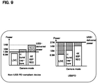
- FIG. 9 is a graph that shows power consumption when main functions of an imaging device are carried out. Examples of the main functions include a live view (LIVE), high-speed burst capturing (H burst capturing), and recording a 4K image at a frame rate of 60P (4k60P REC).
- the imaging device consumes about 10 W of power for high-speed burst capturing, and 14 W of power for 4k60P REC, as shown in FIG. 10.
- USB PD-compliant device As shown in the right-hand graph of FIG. 9 , not only is it possible to provide the drive power needed to carry out the main functions of the imaging device, excess power from the power delivery (slanted-line parts in the right-hand graph) can be used to charge the battery.
- Embodiment 1 An imaging device according to Embodiment 1 is described below with reference to FIGS. 1 to 5 .
- FIG. 1 shows an overall configuration of an imaging device 1 according to Embodiment 1.
- the imaging device 1 is, for example, an integrated-lens digital camera capable of imaging still images and/or moving images.
- the imaging device 1 comprises a sub microcomputer 11, a charging integrated circuit (IC) 12, a PD controller 13, a status liquid-crystal monitor 15, a USB port 16, an analog switch 17, a power source switch-monitoring integrated circuit (IC) 18, a power source integrated circuit (IC) 19, and a battery 20. These components activate in a control of power supply to the imaging device 1, as is described hereinafter.
- the imaging device 1 further comprises a body controller 30, an operation unit 33, a flash memory 34, a liquid crystal monitor 35, a wireless communication unit 36, a CMOS image sensor 37, a sound output unit 38, and a memory card 40.
- the imaging device 1 also comprises an optical system 50 securely attached to a body of the imaging device. Through actions of the body controller 30, these components carry out the main functions of the imaging device 1.
- the main functions of the imaging device 1 include imaging, image processing, inputting/outputting image data, writing and/or reading of image data in a recording medium, update processing of firmware and other software, etc.
- dashed-line arrows indicate a flow of a signal relating to power supply
- solid-line arrows indicate a flow of a serial signal or a parallel signal for other communications and/or controls. Functions of the components including signal exchange are described below.
- the sub microcomputer 11 includes a CPU and/or a memory such as a ROM and a RAM.
- the sub microcomputer 11 switches the analog switch 17 and inputs a D+/D- signal from the USB port 16 to the body controller 30, the sub microcomputer 11, or the charging IC 12.
- the sub microcomputer 11 obtains a result of a port determination from the charging IC 12.
- the sub microcomputer 11 detects a signal (High signal or Low signal) generated in response to fitting and removing of the battery 20 when the power source is OFF, and determines whether or not the battery 20 is fitted in.
- the sub microcomputer 11 acquires a remaining charge of the battery 20. For the remaining charge of the battery 20, for example, a voltage value of the battery 20 may be monitored by the power source IC 19, and the remaining charge of the battery 20 may be acquired in accordance with the voltage value.
- the charging IC 12 controls the supply of power from the USB port 16. Through this control, power obtained from the USB port 16 is used to charge the battery 20 or start up the body controller 30 of the imaging device 1.
- the charging IC 12 is also connected to the sub microcomputer 11, and the charging IC performs a port determination (described hereinafter).
- the port determination determines a type of the connected device. For example, the port determination determines if the connected device is a personal computer (PC), an AC adapter, etc.
- the PD controller 13 performs a negotiation with the connected device via a configuration channel (CC) terminal of the USB port 16. In the negotiation, a direction of power supply between the imaging device 1 and the connected device, a setting of current/voltage, roles of terminals, etc., are decided via the CC terminal, as described hereinafter.
- the sub microcomputer 11 determines whether or not the connected device is a USB PD-compliant device by acquiring the results of the negotiation from the PD controller 13.
- the status liquid-crystal monitor 15 is a display disposed on the body of the imaging device 1 (e.g., on an upper surface of the body), separately from the liquid crystal monitor 35.
- the status liquid-crystal monitor 15 displays messages, etc., that correspond to commands from the sub microcomputer 11.
- the USB port 16 (one example of a power supply terminal) is a type C terminal, and connects an external device to the imaging device 1 via a USB cable (not shown).
- the USB port 16 includes a VBUS terminal for a power source, a GND terminal, the above-described CC terminal, and/or a terminal for D+ and D- signals.
- the connected device has similar terminals, and pulls up a CC and monitors voltage of the CC terminal. The connected device supplies voltage to the VBUS upon detecting a pulling down of the CC on the imaging device 1 side. Power is thereby supplied to the imaging device 1 side.
- the analog switch 17 is switched under control by the sub microcomputer 11, and the analog switch connects the USB port 16 to either the sub microcomputer 11, the body controller 30, or the charging IC 12.
- the analog switch 17 connects the USB port 16 to the charging IC 12, and the charging IC 12 performs a port determination.
- the connected device is, for example, a PC and the PC communicates with the imaging device 1
- the analog switch 17 connects the USB port 16 to the body controller 30.
- the power source IC 19 controls the supply of power from the battery 20.
- the power source IC 19 also performs execution and interruption of the supply of power to the body of the imaging device 1 in accordance with the power source switch of the imaging device 1 being operated ON and OFF.
- the battery 20 supplies power for activating the imaging device 1.
- the battery 20 may be a primary battery or a secondary battery.
- the battery 200 may be an internal battery attached inside the body of the imaging device 1, or an external battery attached to an exterior of the body of the imaging device 1 by a battery grip, etc.
- the body controller 30 (one example of a controller) comprises a main microcomputer 30a, an image processor 31, and a DRAM 32.
- the main microcomputer 30a is a computer device containing a CPU, a RAM and/or ROM and other memory, and peripheral circuitry.
- the main microcomputer 30a controls the actions of the entire imaging device 1, including image processing, in accordance with instructions from the operation unit 33 and/or software written into the ROM.
- the main microcomputer 30a detects a signal (High signal or Low signal) generated by the power source IC 19 in response to fitting and removing of the battery 20 when the power source is ON, and determines whether or not the battery 20 is fitted in.
- the image processor 31 performs prescribed image processing on image data outputted from the CMOS image sensor 37.
- the prescribed image processing includes gamma correction processing, white balance correction processing, flaw correction processing, YC conversion processing, digital zoom processing, shrink processing, stretch processing, etc.
- the DRAM 32 is used as working memory of the body controller 30.
- the body controller 30 also communicates with the connected device through the USB port 16. For example, the body controller 30 communicates with the connected device during mass storage connection and/or tethered shooting.
- the operation unit 33 includes a release button, other types of buttons, a directional keypad, a dial, a touch panel disposed in the liquid crystal monitor 35, etc.
- the user causes the functions of the imaging device 1 to be carried out by operating the operation unit 33.
- the operation unit 33 includes the power source switch of the imaging device 1. When the power source switch is set to ON, the body controller 30 is able to start up and the main functions of the imaging device 1 can be carried out. When the power source switch is set to OFF, the body controller 30 does not start up and the main functions of the imaging device 1 cannot be carried out.
- the flash memory 34 stores image data processed by the body controller 30.
- the flash memory 34 also stores programs and parameters used by the body controller 30.
- the liquid crystal monitor 35 (one example of an output unit) is a display disposed on, for example, a rear surface of the body of the imaging device 1.
- the liquid crystal monitor 35 displays image data (still images or moving images) processed by the image processor 31.
- the liquid crystal monitor 35 displays a setting menu for setting actuating conditions of the imaging device 1.
- the liquid crystal monitor 35 may include a touch panel that functions as part of the operation unit 33. Instead of the liquid crystal monitor 35, an organic EL display or another display may be used.
- the wireless communication unit 36 includes a WiFi- and/or Bluetooth-compliant communication module, and the body controller 30 performs bi-directional communication control with wirelessly connected devices.
- the communication module may use infrared communication, a wireless local area network (LAN), etc., and is preferably capable of connecting wirelessly with external devices.
- LAN wireless local area network
- the sound output unit 38 (one example of an output unit) outputs sound under control by the body controller 30.
- the sound output unit 38 is, for example, a speaker.
- the memory card 40 is fitted in a memory slot, the memory card internally including a semiconductor memory or another storage element.
- the memory card 40 stores image data.
- the body controller 30 reads the image data stored in the memory card 40, processes the read image data through the image processor 31, and displays the image data on the liquid crystal monitor 35.
- a plurality of memory cards 40 e.g., two, may be provided.
- the optical system 50 is configured from a lens barrel and is securely attached to the body of the imaging device 1.
- the optical system 50 includes: a group of lenses including a focus lens, a zoom lens, etc.; a drive unit for the lenses; etc.
- the optical system 50 is controlled and driven by the body controller 30.
- FIG. 2 is a flowchart of an action of the imaging device 1 carried out mainly by the main microcomputer 30a according to Embodiment 1.
- the sub microcomputer 11 detects connection of a USB cable and determines whether or not a USB PD-compliant device is connected to the USB port 16 through a port determination by the charging IC 12 and a negotiation with the connected device by the PD controller 13.
- FIG. 3 is referenced here to describe a negotiation, made via the CC terminal, for detecting that the connected device is a USB PD-compliant device.
- the sub microcomputer 11 applies a power source to the PD controller 13 through power source control (S1311: control power source ON).
- the sub microcomputer 11 implements the requested power/current settings in the PD controller 13 (S1132: initial settings configured).
- the PD controller 13 restarts, and according to a setting value set in S1132, connects to the connected device and initiates the negotiation (S1133).
- the PD controller 13 notifies the sub microcomputer 11 that a plug of a USB cable has been inserted into the USB port 16. In the negotiation, notification of a power delivery capability is given from the connected device to the PD controller 13.
- the PD controller 13 issues a notification to the sub microcomputer 11 stating that a power delivery capability list has been received.
- the sub microcomputer 11 determines whether or not the connected device is a USB PD-compliant device.
- the PD controller 13 then issues a power delivery request to the connected device. Having received this request, the connected device notifies the PD controller 13 of an acceptance of the power delivery and also of a completion of a power delivery preparation.
- the PD controller 13 notifies the sub microcomputer 11 that a "PD contract" including the above-described power delivery condition has been completed (S1134), and the PD contract is completed.
- the sub microcomputer 11 gives the PD controller 13 confirmation of the voltage and current set in the PD contract (S1135).
- the connected device is a USB PD-compliant device.
- An action of the imaging device 1 when the connected device is a USB PD-compliant device will be described below.
- FIG. 2 the power source of the imaging device 1 is turned ON (Sill). As a result, the body controller 30 starts up and the main functions of the imaging device 1 can be carried out.
- FIG. 4 shows a control flow for setting a power source of the imaging device to ON.
- the power source switch-monitoring IC 18 detects that the power source switch has been operated to ON, and transmits a power source ON request signal to the sub microcomputer 11.
- the sub microcomputer 11 transmits the power source ON request signal to the power source IC 19, whereby the power source IC 19 turns ON the power source.
- the main microcomputer 30a detects removing of the battery 20 (S112).
- the main microcomputer 30a detects a signal (High signal or Low signal) generated by the power source IC 19 in response to the removing of the battery 20.
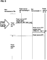
- FIG. 5 shows a control flow for setting the power source to OFF.
- the main microcomputer 30a of the body controller 30 transmits a power source OFF request signal to the sub microcomputer 11.
- the sub microcomputer 11 transmits the power source OFF request signal to the power source IC 19, and the power source IC 19 turns OFF the power source. As a result, power supply from the connected device is cut off.
- the main microcomputer 30a turns OFF the power source(S112) if the power source switch is operated to OFF(Yes in S114).
- the imaging device 1 is an imaging device in and from which a battery 20 can be fitted and removed, the imaging device 1 comprising a USB port 16 and a body controller 30.
- the USB port 16 is connectable to an external device via a USB cable, and delivers power from the external device to the imaging device 1.
- the body controller 30 detects removal of the battery 20 from the imaging device 1 while power is supplied from the external device to the imaging device 1, and in response to the detection, cuts off the supply of power from the external device.
- the imaging device 1 of Embodiment 1 it is possible to retain the power of the battery 20 and prevent power supply from being stopped upon the USB cable being pulled out. This can prevent problems incurred due to the power supply being cut off while a main function of the imaging device 1 is carried out Such problems may include: data being damaged during recording of an image in media; an update of firmware of the body controller 30 stopping partway through and a fault occurring in a program, etc. Consequently, the imaging device 1 can safely receive a supply of power.
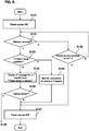
- FIG. 6 is a flowchart of an action of the imaging device 1 according to Embodiment 2.
- the configuration of the imaging device according to the present embodiment is similar to the configuration of the imaging device 1 shown in FIG. 1 , and is therefore not described.
- the power source of the imaging device 1 is turned OFF when removal of the battery 20 is detected.
- the function can be disrupted.
- the power source is turned OFF and an update of firmware of the main microcomputer 30a is stopped partway through, a fault may occur in a program so that the imaging device 1 may not be able to start up.
- the power source it is preferable for the power source not to be turned OFF right away.
- the imaging device 1 according to Embodiment 2 performs the process as shown in FIG. 6 .
- step 111 in FIG. 2 the power source is turned ON (S121), whereby the body controller 30 starts up and the main functions are ready to be carried out.
- the main microcomputer 30a detects removal of the battery 20 (S122).
- the main microcomputer 30a determines whether a firmware is being updated (S123). If the firmware is being updated(Yes in step S123), the main microcomputer 30a waits for completion of the update of the firmware (S124). At this time, the liquid crystal monitor 35 or the sound output unit 38 may output information notifying the firmware being updated. When detecting completion of the update of the firmware, the main microcomputer 30a turns OFF the power source (S127), similarly to step S113.
- the main microcomputer 30a waits for a specific time while causing the liquid crystal monitor 5 to display message (one example of warning information) urging the battery to be fitted in (S125).
- the massage may be output as sound by the sound output unit 38.
- the specific time is, for example, a time (e.g. 5 seconds) for a user to take for changing the battery 20.
- the main microcomputer 30a detects that the battery 20 has been fitted in within the specific time (Yes in S126), as far as the power source is not turned OFF (No in step S128), the power source is kept ON. If the main microcomputer 30a does not detect that the battery 20 is fitted in within the specific time (No in S126), the power source is turned OFF (S127).
- the main microcomputer 30a keeps the power source ON unless the power source is operated to OFF (No in step S128).
- the imaging device 1 When carrying out a specific action, the imaging device 1 according to the present embodiment keeps the power source ON until the specific action is completed while keeping a power supply in a safe manner. Therefore, it is possible to prevent a problem from being caused by stop of power supply while the specific action is carried out. Furthermore, even when the imaging device 1 is not carrying out the specific action, it turns OFF the power source after a lapse of the specific time. As a result, it is possible to prevent the power supply from being suddenly stopped, for example, during change of the battery 20.
- the imaging device may determine whether image data is being recorded or not, in addition to or in place of whether the firmware is being updated in step S123 above. In this case, if the image data (still image or video) is being recorded, the main microcomputer 30a waits for completion of the image data recording. When completion of the image data recording is detected, the power source of the imaging device 1 may be turned OFF. Therefore, the data is prevented from being damaged due to the driving of the imaging device 1 being stopped during the image data recording.
- the imaging device 1 according to the present embodiment does not necessarily execute all of the above processes.
- the imaging device 1 can execute only processes in steps S121 to S127 through S122, S123, and S124 and processes in steps S121 to S127 through S122 and S128 without executing a process relating to a lapse of a specific time.
- the imaging device 1 turns OFF the power source after completing the specific action. If the specific action is not being carried out, it turns OFF the power source.
- the imaging device 1 can execute only processes in steps S121 to S126 through S122 and S125 and processes in steps S121 to S127 through S122 and S128. In this case, if the battery 20 has been removed, the imaging device 1 does not execute a process based on determination on whether the specific action is being carried out. Instead, the imaging device 1 waits for a specific time and then turns OFF the power source unless the battery 20 is fitted in within the specific time.
- Embodiments were described above as examples of the technology disclosed in the present application. However, these embodiments are not provided by way of limitation as to the technology in the present disclosure; this technology can also be applied as appropriate to embodiments in which changes, replacements, additions, omissions, etc., have been made. The constituent elements described in the above embodiments can also be combined to yield new embodiments.
- USB PD-compliant device When connected device is USB PD-compliant device
- charging can be performed in addition to power delivery for the drive power for the imaging device 1 because power equal to or greater than the power consumption of the imaging device 1 can be supplied.
- the connected device is a PC or an AC adapter
- charging is performed when the battery 20 is fitted in the imaging device 1, and charging is not performed when the battery 20 is not fitted in.
- a MASS connection is a connection for transferring large-volume data of an SD card, etc.
- a PTP connection is a connection for transferring image data.
- the connected device is an AC adapter
- charging with the excess power is performed in addition to the delivery of power when the battery is fitted in.
- the power source switch of the imaging device 1 is not turned ON as is described hereinafter, and neither power delivery nor charging is performed.
- the connected device is a PC or an AC adapter
- charging is performed when the battery 20 is fitted in the imaging device 1, and charging is not performed when the battery 20 is not fitted in.
- the connected device is a PC
- only a MASS connection or a PTP connection and power delivery are performed.
- the connected device is an AC adapter
- only power delivery is performed.
- the computer program described above is not limited to being recorded on the recording medium described above; the computer program may be acquired via an electric communication circuit, a wireless or wired communication circuit, networks typified by the internet, etc.
- the present disclosure can be applied to a digital camera, a movie camera, a portable phone with a camera, and other electronic devices provided with an imaging function.
- Patent Literature 1 Japanese Laid-open Patent Publication No. 2013-80392
Landscapes
- Engineering & Computer Science (AREA)
- Multimedia (AREA)
- Signal Processing (AREA)
- Physics & Mathematics (AREA)
- General Physics & Mathematics (AREA)
- Studio Devices (AREA)
- Camera Bodies And Camera Details Or Accessories (AREA)
- Indication In Cameras, And Counting Of Exposures (AREA)
- Accessories Of Cameras (AREA)
Applications Claiming Priority (2)
| Application Number | Priority Date | Filing Date | Title |
|---|---|---|---|
| JP2018237560 | 2018-12-19 | ||
| PCT/JP2019/033075 WO2020129304A1 (ja) | 2018-12-19 | 2019-08-23 | 撮像装置 |
Publications (3)
| Publication Number | Publication Date |
|---|---|
| EP3901697A1 true EP3901697A1 (de) | 2021-10-27 |
| EP3901697A4 EP3901697A4 (de) | 2022-02-09 |
| EP3901697B1 EP3901697B1 (de) | 2025-10-01 |
Family
ID=71102780
Family Applications (1)
| Application Number | Title | Priority Date | Filing Date |
|---|---|---|---|
| EP19874763.6A Active EP3901697B1 (de) | 2018-12-19 | 2019-08-23 | Bildgebungsvorrichtung |
Country Status (4)
| Country | Link |
|---|---|
| US (1) | US11184533B2 (de) |
| EP (1) | EP3901697B1 (de) |
| JP (1) | JPWO2020129304A1 (de) |
| WO (1) | WO2020129304A1 (de) |
Families Citing this family (2)
| Publication number | Priority date | Publication date | Assignee | Title |
|---|---|---|---|---|
| JP7527164B2 (ja) * | 2020-09-09 | 2024-08-02 | キヤノン株式会社 | 撮像装置、制御方法及びプログラム |
| JP2024037061A (ja) * | 2022-09-06 | 2024-03-18 | キヤノン株式会社 | 撮像装置、アクセサリ、撮像システム、撮像装置およびアクセサリの制御方法、並びにプログラム |
Family Cites Families (27)
| Publication number | Priority date | Publication date | Assignee | Title |
|---|---|---|---|---|
| JPH0488411A (ja) * | 1990-07-25 | 1992-03-23 | Sharp Corp | 小型電子機器における電源電圧検知装置 |
| JPH06178452A (ja) | 1992-12-09 | 1994-06-24 | Matsushita Electric Works Ltd | 充交両用電気機器 |
| JP4593834B2 (ja) * | 2001-07-02 | 2010-12-08 | 富士フイルム株式会社 | デジタルカメラ及びそのシステム |
| JP2003101624A (ja) * | 2001-09-26 | 2003-04-04 | Toshiba Corp | 携帯端末 |
| JP2004227381A (ja) | 2003-01-24 | 2004-08-12 | Matsushita Electric Ind Co Ltd | 情報端末機器 |
| JP4355250B2 (ja) * | 2004-03-31 | 2009-10-28 | Hoya株式会社 | デジタルカメラ |
| JP2007158604A (ja) * | 2005-12-02 | 2007-06-21 | Canon Inc | 撮像装置及びその制御方法 |
| JP2007214786A (ja) * | 2006-02-08 | 2007-08-23 | Toshiba Corp | 携帯型撮像装置 |
| JP2007329519A (ja) * | 2006-06-06 | 2007-12-20 | Hitachi Ltd | 情報記録装置、情報処理装置 |
| JP5628022B2 (ja) * | 2009-12-28 | 2014-11-19 | パナソニック株式会社 | 電子機器及び給電制御方法 |
| JP2013080392A (ja) | 2011-10-04 | 2013-05-02 | Olympus Imaging Corp | 携帯装置のusb充電 |
| JP2013135347A (ja) * | 2011-12-27 | 2013-07-08 | Xacti Corp | 記録装置 |
| JP2013140463A (ja) * | 2011-12-29 | 2013-07-18 | Sony Corp | 撮像装置および電源供給方法 |
| JP2013239060A (ja) * | 2012-05-16 | 2013-11-28 | Seiko Epson Corp | 印刷装置用の電源回路 |
| JP6288913B2 (ja) * | 2012-12-28 | 2018-03-07 | キヤノン株式会社 | 電子機器及びプログラム |
| JP2014188931A (ja) * | 2013-03-28 | 2014-10-06 | Seiko Epson Corp | 印刷装置 |
| US10514744B2 (en) * | 2015-08-16 | 2019-12-24 | The Code Corporation | Portable computing device with hibernate mode |
| WO2017029839A1 (ja) * | 2015-08-18 | 2017-02-23 | オリンパス株式会社 | ワイヤレス内視鏡 |
| CN107493462B (zh) * | 2016-06-13 | 2020-11-27 | 中兴通讯股份有限公司 | 视频处理设备 |
| JP6797579B2 (ja) * | 2016-07-04 | 2020-12-09 | キヤノン株式会社 | 電子機器、電子機器の制御方法及びプログラム |
| JP6714469B2 (ja) * | 2016-08-24 | 2020-06-24 | キヤノン株式会社 | 電子機器およびその制御方法 |
| JP2018106555A (ja) * | 2016-12-27 | 2018-07-05 | キヤノン株式会社 | 電子機器及びその制御方法、プログラム、記憶媒体 |
| JP2019062690A (ja) * | 2017-09-27 | 2019-04-18 | パナソニックIpマネジメント株式会社 | 充電装置および電子機器 |
| JP7130373B2 (ja) * | 2018-01-09 | 2022-09-05 | キヤノン株式会社 | 撮像装置 |
| JP7148293B2 (ja) * | 2018-06-29 | 2022-10-05 | キヤノン株式会社 | 電子機器及び電子機器の制御方法及び撮像装置 |
| JP7143173B2 (ja) * | 2018-09-28 | 2022-09-28 | キヤノン株式会社 | 電子機器、制御方法およびプログラム |
| JP7218137B2 (ja) * | 2018-10-10 | 2023-02-06 | キヤノン株式会社 | 電子装置およびその制御方法 |
-
2019
- 2019-08-23 JP JP2019566703A patent/JPWO2020129304A1/ja active Pending
- 2019-08-23 EP EP19874763.6A patent/EP3901697B1/de active Active
- 2019-08-23 US US16/765,774 patent/US11184533B2/en active Active
- 2019-08-23 WO PCT/JP2019/033075 patent/WO2020129304A1/ja not_active Ceased
Also Published As
| Publication number | Publication date |
|---|---|
| US11184533B2 (en) | 2021-11-23 |
| US20210227135A1 (en) | 2021-07-22 |
| WO2020129304A1 (ja) | 2020-06-25 |
| JPWO2020129304A1 (ja) | 2021-11-25 |
| EP3901697A4 (de) | 2022-02-09 |
| EP3901697B1 (de) | 2025-10-01 |
Similar Documents
| Publication | Publication Date | Title |
|---|---|---|
| US9047073B2 (en) | System method for detecting a type of device wherein a potential level of the device determines if power should be supplied based on the type of the device | |
| EP3780328B1 (de) | Reverse-charging-vorrichtung | |
| US11239684B2 (en) | Electronic device and control method | |
| US11176078B2 (en) | Communication method using input/output interface, and apparatus therefor | |
| JP5382045B2 (ja) | 電子機器、電子機器システムおよびプログラム | |
| US9395781B2 (en) | Electronic device to perform enumeration without power request to an external device when electronic device is on | |
| US11736790B2 (en) | Electronic device and control method | |
| EP3699686B1 (de) | Bildaufnahmevorrichtung | |
| EP3901697B1 (de) | Bildgebungsvorrichtung | |
| CN111886852B (zh) | 摄像装置 | |
| JP2013080392A (ja) | 携帯装置のusb充電 | |
| US11405550B2 (en) | Imaging device with battery prioritization | |
| US11431885B2 (en) | Communication apparatus including a communication device for communicating with an external apparatus, and to control in activating the communication device by the communication apparatus and method for controlling the same | |
| JP6176920B2 (ja) | 電子機器、制御方法及びプログラム | |
| CN119440207A (zh) | 电子设备、控制方法、存储介质及程序产品 | |
| JP5169598B2 (ja) | 画像転送装置およびカメラ | |
| JP2021032979A (ja) | 撮像装置 |
Legal Events
| Date | Code | Title | Description |
|---|---|---|---|
| STAA | Information on the status of an ep patent application or granted ep patent |
Free format text: STATUS: UNKNOWN |
|
| STAA | Information on the status of an ep patent application or granted ep patent |
Free format text: STATUS: THE INTERNATIONAL PUBLICATION HAS BEEN MADE |
|
| PUAI | Public reference made under article 153(3) epc to a published international application that has entered the european phase |
Free format text: ORIGINAL CODE: 0009012 |
|
| STAA | Information on the status of an ep patent application or granted ep patent |
Free format text: STATUS: REQUEST FOR EXAMINATION WAS MADE |
|
| 17P | Request for examination filed |
Effective date: 20210521 |
|
| AK | Designated contracting states |
Kind code of ref document: A1 Designated state(s): AL AT BE BG CH CY CZ DE DK EE ES FI FR GB GR HR HU IE IS IT LI LT LU LV MC MK MT NL NO PL PT RO RS SE SI SK SM TR |
|
| A4 | Supplementary search report drawn up and despatched |
Effective date: 20220110 |
|
| RIC1 | Information provided on ipc code assigned before grant |
Ipc: H04N 5/232 20060101ALI20220103BHEP Ipc: G03B 17/56 20210101ALI20220103BHEP Ipc: G03B 17/02 20210101AFI20220103BHEP |
|
| DAV | Request for validation of the european patent (deleted) | ||
| DAX | Request for extension of the european patent (deleted) | ||
| STAA | Information on the status of an ep patent application or granted ep patent |
Free format text: STATUS: EXAMINATION IS IN PROGRESS |
|
| 17Q | First examination report despatched |
Effective date: 20231102 |
|
| RIC1 | Information provided on ipc code assigned before grant |
Ipc: H04N 23/65 20230101ALI20250409BHEP Ipc: H04N 23/63 20230101ALI20250409BHEP Ipc: G03B 17/56 20210101ALI20250409BHEP Ipc: G03B 17/02 20210101AFI20250409BHEP |
|
| GRAP | Despatch of communication of intention to grant a patent |
Free format text: ORIGINAL CODE: EPIDOSNIGR1 |
|
| STAA | Information on the status of an ep patent application or granted ep patent |
Free format text: STATUS: GRANT OF PATENT IS INTENDED |
|
| INTG | Intention to grant announced |
Effective date: 20250521 |
|
| GRAS | Grant fee paid |
Free format text: ORIGINAL CODE: EPIDOSNIGR3 |
|
| GRAA | (expected) grant |
Free format text: ORIGINAL CODE: 0009210 |
|
| STAA | Information on the status of an ep patent application or granted ep patent |
Free format text: STATUS: THE PATENT HAS BEEN GRANTED |
|
| AK | Designated contracting states |
Kind code of ref document: B1 Designated state(s): AL AT BE BG CH CY CZ DE DK EE ES FI FR GB GR HR HU IE IS IT LI LT LU LV MC MK MT NL NO PL PT RO RS SE SI SK SM TR |
|
| REG | Reference to a national code |
Ref country code: GB Ref legal event code: FG4D Ref country code: CH Ref legal event code: F10 Free format text: ST27 STATUS EVENT CODE: U-0-0-F10-F00 (AS PROVIDED BY THE NATIONAL OFFICE) Effective date: 20251001 |
|
| REG | Reference to a national code |
Ref country code: DE Ref legal event code: R096 Ref document number: 602019076484 Country of ref document: DE |