EP3887701B1 - Connector socket, connector assembly, cooling plate and cooling system including the connector socket - Google Patents
Connector socket, connector assembly, cooling plate and cooling system including the connector socket Download PDFInfo
- Publication number
- EP3887701B1 EP3887701B1 EP18815967.7A EP18815967A EP3887701B1 EP 3887701 B1 EP3887701 B1 EP 3887701B1 EP 18815967 A EP18815967 A EP 18815967A EP 3887701 B1 EP3887701 B1 EP 3887701B1
- Authority
- EP
- European Patent Office
- Prior art keywords
- connector
- collar structure
- spigot
- snap
- ring
- Prior art date
- Legal status (The legal status is an assumption and is not a legal conclusion. Google has not performed a legal analysis and makes no representation as to the accuracy of the status listed.)
- Active
Links
Images

Classifications
-
- F—MECHANICAL ENGINEERING; LIGHTING; HEATING; WEAPONS; BLASTING
- F16—ENGINEERING ELEMENTS AND UNITS; GENERAL MEASURES FOR PRODUCING AND MAINTAINING EFFECTIVE FUNCTIONING OF MACHINES OR INSTALLATIONS; THERMAL INSULATION IN GENERAL
- F16L—PIPES; JOINTS OR FITTINGS FOR PIPES; SUPPORTS FOR PIPES, CABLES OR PROTECTIVE TUBING; MEANS FOR THERMAL INSULATION IN GENERAL
- F16L37/00—Couplings of the quick-acting type
- F16L37/008—Couplings of the quick-acting type for branching pipes; for joining pipes to walls
-
- F—MECHANICAL ENGINEERING; LIGHTING; HEATING; WEAPONS; BLASTING
- F16—ENGINEERING ELEMENTS AND UNITS; GENERAL MEASURES FOR PRODUCING AND MAINTAINING EFFECTIVE FUNCTIONING OF MACHINES OR INSTALLATIONS; THERMAL INSULATION IN GENERAL
- F16L—PIPES; JOINTS OR FITTINGS FOR PIPES; SUPPORTS FOR PIPES, CABLES OR PROTECTIVE TUBING; MEANS FOR THERMAL INSULATION IN GENERAL
- F16L41/00—Branching pipes; Joining pipes to walls
- F16L41/001—Branching pipes; Joining pipes to walls the wall being a pipe plate
-
- F—MECHANICAL ENGINEERING; LIGHTING; HEATING; WEAPONS; BLASTING
- F16—ENGINEERING ELEMENTS AND UNITS; GENERAL MEASURES FOR PRODUCING AND MAINTAINING EFFECTIVE FUNCTIONING OF MACHINES OR INSTALLATIONS; THERMAL INSULATION IN GENERAL
- F16L—PIPES; JOINTS OR FITTINGS FOR PIPES; SUPPORTS FOR PIPES, CABLES OR PROTECTIVE TUBING; MEANS FOR THERMAL INSULATION IN GENERAL
- F16L5/00—Devices for use where pipes, cables or protective tubing pass through walls or partitions
- F16L5/02—Sealing
- F16L5/027—Sealing by means of a joint of the quick-acting type
-
- F—MECHANICAL ENGINEERING; LIGHTING; HEATING; WEAPONS; BLASTING
- F28—HEAT EXCHANGE IN GENERAL
- F28F—DETAILS OF HEAT-EXCHANGE AND HEAT-TRANSFER APPARATUS, OF GENERAL APPLICATION
- F28F9/00—Casings; Header boxes; Auxiliary supports for elements; Auxiliary members within casings
- F28F9/02—Header boxes; End plates
- F28F9/0246—Arrangements for connecting header boxes with flow lines
- F28F9/0248—Arrangements for sealing connectors to header boxes
-
- Y—GENERAL TAGGING OF NEW TECHNOLOGICAL DEVELOPMENTS; GENERAL TAGGING OF CROSS-SECTIONAL TECHNOLOGIES SPANNING OVER SEVERAL SECTIONS OF THE IPC; TECHNICAL SUBJECTS COVERED BY FORMER USPC CROSS-REFERENCE ART COLLECTIONS [XRACs] AND DIGESTS
- Y02—TECHNOLOGIES OR APPLICATIONS FOR MITIGATION OR ADAPTATION AGAINST CLIMATE CHANGE
- Y02E—REDUCTION OF GREENHOUSE GAS [GHG] EMISSIONS, RELATED TO ENERGY GENERATION, TRANSMISSION OR DISTRIBUTION
- Y02E60/00—Enabling technologies; Technologies with a potential or indirect contribution to GHG emissions mitigation
- Y02E60/10—Energy storage using batteries
Definitions
- the invention relates to a connector assembly for liquid flows, for example for cooling liquids.
- the document US 2004/083884 A1 discloses a connector socket for a brake booster.
- the document JP5807720A discloses flange plate for a bearing as used in a gear transmission having a double-layered collar structure where the folds are oriented in the radial direction.
- the document JP2001349689A discloses a collar provided on a portion reinforced by non-circular ribs.
- the mounting normally requires tools, e.g. for screwing to generate a sufficient contact pressure for sealing the connection. This is burdensome and a source of potential errors.
- the invention seeks to overcome these problems by providing a compact, light and easy to use connector assembly, plate for use with such an assembly and a cooling system including such an assembly.
- the invention relates to a connector socket for connecting a spigot to an orifice, said connector socket including a sheet metal plate with said orifice and a protruding collar structure surrounding said orifice.
- said collar structure is integrally made of the sheet metal of said sheet metal plate by a sheet metal form ⁇ ing process.
- the collar structure By forming the collar structure integrally with the sheet metal plate using sheet metal forming process, additional manufacturing steps including brazing or welding can be avoided and the manufacturing process can be simplified.
- the collar structure can be very rigid and virtually impossible to break off.
- the structure itself forms a reinforcing rib. Impurities resulting from brazing or welding processes or leakage due to imperfect welding can be avoided.
- the sheet metal forming process may include different techniques such as stamping, deep-drawing, punching, blanking, stamping, embossing, bending, forming, tap extrusion or coil extrusion, optionally complemented by laser cutting.
- the spigot may be designed e.g. for use with liquids such as coolants or cooling liquids.
- the invention further proposes that the collar structure is configured to receive a male end of said spigot. This lends additional stability by a deep seating of the spigot in the socket.
- the socket further includes a connector means mediating the connection of the spigot with the collar structure.
- the connector means further includes a ring-shaped snap-on module configured to be fitted over the collar structure, said snap-on module including a cylindrical insertion part configured to be inserted into an orifice of said collar structure, wherein a remote end of the cylindrical insertion part in the insertion direction is provided with first snap-on structures engaging with the collar structure.
- the snap-on module enables an easy assembly even without tools while providing a reliable, robust and precise connection structure for the spigot.
- the invention in particular in the embodiment with the snap-on module, lends itself in particular to applications where the spigot has to be mounted from the outside of the container or receptacle if there is no possibility reach the inside thereof.
- the connector means is configured to create a snap-lock connection with both the collar structure and with the male end of the spigot. This enables an easy mounting of the entire assembly without tools.
- cylindrical inner wall of the insertion part of the ring-shaped snap-on module is provided a notch configured to receive an 0-ring.
- the first 0-ring can provide a reliable sealing between the inner wall of the orifice in the snap-on module and the outer wall of the male end of the spigot.
- an inner circumference of the collar structure includes a structure such as a notch or a flange configured to support a second 0-ring to be arranged between collar structure and the outer wall of the insertion part.
- the second 0-ring can ensure a reliable sealing between the snap-on module and the collar structure.
- the inventor further proposes that a second 0-ring is provided around an outer wall of the collar structure and/or that the ring-shaped snap-on module further includes an outer wall surrounding said collar structure and a second 0-ring provided in a gap between the outer wall of the snap-on module and the collar structure.
- the second 0-ring can ensure a reliable sealing between the snap-on module and the collar structure.
- the 0-ring on the inner side of the collar structure and the 0-ring on the outer side of the collar structure may be used alone or in combination.
- the ring-shaped snap-on module is a plastic part.
- the plastic can be chosen according to the chemical and thermal requirements imposed by the application and may include fibre reinforcement or metal reinforcement if necessary.
- the collar structure is a cylindrical double layer structure obtained by folding the sheet metal back, the rim of the sheet metal being arranged on the inside of the collar structure.
- the rim may then be used as a stable, sharp and well-defined engagement point for latching structures of the spigot or of the ring-shaped snap-on module.
- the male end of said spigot includes at least one latching structure on a radial outside surface of its end portion, said latching structures being configured to interact with corresponding latching structures on a cylindrical inner surface of said connector means. This enables an easy and simple snap-on assembly of the spigot without requiring special tools.
- the latching structure on the radial outside surface of the end portion of the spigot is configured to engage around a rim of the cylindrical inner surface of said connector means.
- the cylindrical inner surface of said connector means is a cylindrical inner surface of said ring-shaped snap-on module.
- a yet further aspect of the invention relates to a cooling system, in particular for battery assemblies, including a connector socket and/or connector assembly as defined above.
- Figure 1 to 3 show a connector socket and a connector assembly according to a first embodiment of the invention.
- the connector assembly is configured for use in a battery cooling system of an electric or hybrid vehicle and guides the cooling liquid to a heat exchanger.
- One of the walls of the heat exchanger is a sheet metal plate 10 having an orifice 10a.
- a spigot 12 is to be attached to the orifice 10a.
- the spigot 12 has an internal, angular flow path for liquid, e.g. coolant or water ending in an orifice 10c of the spigot 10c arranged within the orifice 10a of the plate 10.
- Connector means 14 are provided for connecting the spigot 12 to the metal plate 10 so as to guide the liquid flowing in the flow path through the orifice 10c.
- the connector means 14 include a connector socket, which has a protruding collar structure 16 surrounding the orifice 10a.
- the collar structure 16 is integrally made of the sheet metal of said sheet metal plate 10 by a sheet metal forming process such as punching and deep-drawing.
- the circular cylindrical collar structure 16 protrudes from the sheet metal plate 10 as a roughly cylinder-barrel shaped circular wall in a direction perpendicular to a main plane or tangential plane of the sheet metal plate 10. From a viewpoint of stiffness, the collar structure is a circular reinforcing rib of the sheet metal plate.
- the collar structure 16 lends stability to the connection between the spigot 12 and the sheet metal plate 10 and stabilizes the rim of the orifice 10a provided in the centre of the collar structure 16.
- the collar structure 16 has double layer structure obtained by folding the sheet metal back, the rim of the sheet metal being arranged on the inside of the collar structure 16.
- the connector means 14 further includes a ring-shaped snap-on module 18 formed as an injection-moulded plastic part configured to be fitted over the collar structure 16.
- the snap-on module 18 includes a cylindrical insertion part 18a configured to be inserted into an orifice 10a of said collar structure 16, wherein a remote end of the cylindrical insertion part 18a in the insertion direction is provided with a plurality of latches 18b with snap-fitting protrusions protruding radially outward as first snap-on structures engaging with the lower rim of the collar structure 16.
- the cylindrical inner wall of the insertion part 18a of the ring-shaped snap-on module 18 is provided with a notch 18c configured to receive a first O-ring 20.
- a male end of said spigot 12 is configured to be inserted into an orifice 10b of the ring-shaped snap-on module 18 and thus into the collar structure 16 and locked in place by interacting with the connector means 14.
- a flange 28 of the spigot limits the depth of its insertion into the snap-on module 18. The inward deflection of the latches 18b is blocked by the inserted spigot 12.
- the male end of said spigot 12 includes a plurality latching structure on a radial outside surface of its end portion, the latching structures being configured to engage with the lower rim of the cylindrical inner surface of the ring-shaped snap-on module 18.
- the latches 18b When inserting the cylindrical insertion part 18a into the orifice 10a of the collar structure 16, the latches 18b are deflected radially inward and snap back upon reaching the final engagement position. As illustrated in Fig. 3 , the latching ends of the spigot 12 protrude slightly over the inner (lower) surface of the snap-on module 18.
- the ring-shaped snap-on module 18 further includes an outer wall surrounding the collar structure 16 and abutting to the radially outer wall of the collar structure 16 such that the overall profile of the ring-shaped snap-on module 16 is that of a reverse U-shape clipped onto the collar structure 16.
- a second O-ring 22 sealing the connection between the snap-on module 18 and the metal plate 10 is arranged on an inner circumference of the collar structure 16, wherein the latter includes a flange 16a protruding radially inward configured to support the second O-ring 22 arranged between collar structure 16 and the outer wall of the insertion part 18a.
- the remote end of the spigot 12 is configured with a barb structure fitting into a coolant hose, which may for example be further fixed by a hose clamp.
- the structure of the remote end of the spigot 12 is not particularly limited and may be of any structure suitable for connecting hoses or tubes.
- Fig. 4 is an explosion view of the connector assembly including the spigot 12, the snap-on module 18, the first O-ring 20 sealing the connection between spigot 12 and snap-on module 18 and the second O-ring 22 sealing the connection between the snap-on module 18 and the metal plate 10.
- the ring-shaped snap-on module 18 may be pre-assembled and snapped on the collar structure 16 of the metal plate 10 in an easily transportable unit without requiring special tools.
- the pre-assembled structure is illustrated in Fig. 5 .
- the pre-assembled unit can be transported without risk of loss of the snap-on module 18 and the spigot 12 and a hose can then be attached in the final assembly of the application using the connector assembly.
- the sheet metal plate 10 with the collar structure 16 is part of a cooling plate, heat exchanger or battery plate assembly but is not limited thereto.
- the invention can be applied to an easy connectable spigot 12 for all kinds of receptacles in any material.
- the sheet metal plate 10 and the connector assembly are suitable for use in a cooling system, in particular for battery assemblies, for transporting cooling liquids.
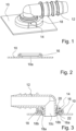
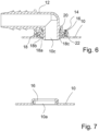
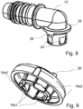
- Figures 6 to 9 show a connector assembly , a collar structure, a spigot and a snap-on module, not parts of the present invention.
- an O-ring 22 is provided in a gap between the outer wall and the collar structure 16 to seal the connection between the snap-on module 18 and the sheet metal plate 10.
- the flange on the inside of the collar structure 16 can be dispensed with in this embodiment.
- Fig. 8 and 9 illustrate a spigot 12 and a snap-on module of a connector assembly, wherein the end portion of the spigot 12 to be inserted into the orifice 10b of the snap-on module 18 is provided with recesses 24 accommodating inwardly protruding end portions of a subset of latches 18b1 of the snap-on module 18.
- a second subset of latches 18b2 engages radially outward with the orifice 10a of the sheet metal plate 10 (not illustrated).
- the limited width of the recesses 24 in the circumferential direction define the relative rotational position of the spigot 12 and the snap-on module 18, which is further defined by mating structures 26, 26' on an upper surface of the snap-on module 18 and on a flange 28 of the spigot 12.
Landscapes
- Engineering & Computer Science (AREA)
- General Engineering & Computer Science (AREA)
- Mechanical Engineering (AREA)
- Physics & Mathematics (AREA)
- Thermal Sciences (AREA)
- Quick-Acting Or Multi-Walled Pipe Joints (AREA)
- Secondary Cells (AREA)
- Motor Or Generator Cooling System (AREA)
- Connector Housings Or Holding Contact Members (AREA)
- Coupling Device And Connection With Printed Circuit (AREA)
- Battery Mounting, Suspending (AREA)
Priority Applications (1)
| Application Number | Priority Date | Filing Date | Title |
|---|---|---|---|
| PL18815967.7T PL3887701T3 (pl) | 2018-11-29 | 2018-11-29 | Gniazdo złącza, zespół złącza, płyta chłodząca i układ chłodzenia zawierający gniazdo złącza |
Applications Claiming Priority (1)
| Application Number | Priority Date | Filing Date | Title |
|---|---|---|---|
| PCT/EP2018/083068 WO2020108764A1 (en) | 2018-11-29 | 2018-11-29 | Connector socket, connector assembly, cooling plate and cooling system including a connector socket |
Publications (3)
| Publication Number | Publication Date |
|---|---|
| EP3887701A1 EP3887701A1 (en) | 2021-10-06 |
| EP3887701B1 true EP3887701B1 (en) | 2025-03-19 |
| EP3887701C0 EP3887701C0 (en) | 2025-03-19 |
Family
ID=64664239
Family Applications (1)
| Application Number | Title | Priority Date | Filing Date |
|---|---|---|---|
| EP18815967.7A Active EP3887701B1 (en) | 2018-11-29 | 2018-11-29 | Connector socket, connector assembly, cooling plate and cooling system including the connector socket |
Country Status (11)
| Country | Link |
|---|---|
| US (1) | US11835166B2 (pl) |
| EP (1) | EP3887701B1 (pl) |
| JP (1) | JP7213350B2 (pl) |
| KR (1) | KR102587118B1 (pl) |
| CN (1) | CN113167411B (pl) |
| BR (1) | BR112021008885B1 (pl) |
| CA (1) | CA3118970C (pl) |
| ES (1) | ES3018409T3 (pl) |
| MX (1) | MX2021005563A (pl) |
| PL (1) | PL3887701T3 (pl) |
| WO (1) | WO2020108764A1 (pl) |
Families Citing this family (7)
| Publication number | Priority date | Publication date | Assignee | Title |
|---|---|---|---|---|
| FR3086381B1 (fr) * | 2018-09-25 | 2022-05-20 | Valeo Systemes Thermiques | Adaptateur pour collecteur d'un echangeur de chaleur |
| EP3855108A1 (en) * | 2020-01-23 | 2021-07-28 | Valeo Autosystemy SP. Z.O.O. | A plate and spigot connection system |
| DE202020103791U1 (de) | 2020-06-30 | 2021-10-04 | Reinz-Dichtungs-Gmbh | Stutzen zur Anbringung an einem plattenartigen Fluidbehälter sowie ein plattenartiger Fluidbehälter mit einem derartigen Stutzen |
| FR3115089A1 (fr) * | 2020-10-09 | 2022-04-15 | Psa Automobiles Sa | Dispositif de traversee de paroi |
| KR102712606B1 (ko) * | 2020-11-05 | 2024-09-30 | 주식회사 엘지에너지솔루션 | 쿨런트 포트 어셈블리 |
| DE102021126530A1 (de) | 2021-10-13 | 2023-04-13 | Benteler Automobiltechnik Gmbh | Temperiervorrichtung für Batteriemodule |
| FR3132943B1 (fr) * | 2022-02-18 | 2024-04-12 | A Raymond Et Cie | Dispositif d’échange thermique et procédé de raccordement dudit dispositif |
Citations (1)
| Publication number | Priority date | Publication date | Assignee | Title |
|---|---|---|---|---|
| JP2001349689A (ja) * | 2000-04-27 | 2001-12-21 | Valeo Thermique Moteur | マニホールドを小型化した自動車用熱交換器 |
Family Cites Families (20)
| Publication number | Priority date | Publication date | Assignee | Title |
|---|---|---|---|---|
| FR1322978A (fr) * | 1962-02-22 | 1963-04-05 | Chausson Usines Sa | Dispositif pour le raccordement d'une boîte à eau d'un échangeur de chaleur avec une tubulure, notamment une tubulure d'amenée de liquide |
| DE2353362C3 (de) * | 1973-10-25 | 1982-05-13 | Süddeutsche Kühlerfabrik Julius Fr. Behr GmbH & Co KG, 7000 Stuttgart | Wasserkasten für Wärmetauscher |
| JPS5877720A (ja) | 1981-10-31 | 1983-05-11 | Aisin Warner Ltd | 3重折りボス部付環状フランジ板の製造方法 |
| JPH0542893Y2 (pl) * | 1987-09-08 | 1993-10-28 | ||
| JPH082464Y2 (ja) * | 1989-04-18 | 1996-01-29 | 臼井国際産業株式会社 | フユーエルデリバリパイプ |
| US5131572A (en) * | 1990-09-24 | 1992-07-21 | Tolco Corporation | Jug and dispensing valve |
| JPH078947Y2 (ja) * | 1991-10-29 | 1995-03-06 | 株式会社ヒロテック | フランジ付パイプの結合構造 |
| JPH0618130U (ja) * | 1992-08-17 | 1994-03-08 | トキコ株式会社 | 気圧式倍力装置 |
| DE29802029U1 (de) * | 1998-02-06 | 1998-03-26 | Anton Hummel Verwaltungs Gmbh, 79183 Waldkirch | Anschlußarmatur mit axial vorstehendem Befestigungsvorsprung |
| JP2000088167A (ja) * | 1998-09-18 | 2000-03-31 | Usui Internatl Ind Co Ltd | 分岐管の接続構造 |
| EP1373040B1 (de) * | 2001-03-21 | 2010-04-28 | Continental Teves AG & Co. oHG | Bremskraftverstärker mit einem anschlusselement mit definierter winkellage |
| JP4588933B2 (ja) * | 2001-07-10 | 2010-12-01 | 株式会社ティラド | 樹脂製パイプとタンクとの接続構造 |
| US6942255B2 (en) * | 2002-04-23 | 2005-09-13 | Q3Jmc, Inc. | Twist fitting for air tank connections |
| JP2004100864A (ja) * | 2002-09-11 | 2004-04-02 | Tacmina Corp | 継手装置 |
| DE102004016051B4 (de) * | 2003-08-18 | 2014-08-28 | Continental Teves Ag & Co. Ohg | Bremskraftverstärker |
| JP5182540B2 (ja) * | 2004-12-07 | 2013-04-17 | トヨタ自動車株式会社 | 燃料電池用ケース |
| US7862090B1 (en) * | 2007-12-28 | 2011-01-04 | R.L. Hudson & Company | Plug-in fitting for direct connection to housing |
| KR101210861B1 (ko) * | 2012-01-17 | 2012-12-11 | 오두만 | 고온고압의 기체가 흐르는 관로의 플랜지 접속을 위한 스테인리스 가스켓의 제조방법 |
| DE202012102342U1 (de) * | 2012-06-26 | 2013-10-02 | Voss Automotive Gmbh | Anschlussvorrichtung für Rohrleitungen |
| JP6299681B2 (ja) * | 2015-06-17 | 2018-03-28 | マツダ株式会社 | 電動車両用バッテリの冷却構造 |
-
2018
- 2018-11-29 BR BR112021008885-7A patent/BR112021008885B1/pt active IP Right Grant
- 2018-11-29 CN CN201880099816.0A patent/CN113167411B/zh active Active
- 2018-11-29 US US17/297,482 patent/US11835166B2/en active Active
- 2018-11-29 WO PCT/EP2018/083068 patent/WO2020108764A1/en not_active Ceased
- 2018-11-29 PL PL18815967.7T patent/PL3887701T3/pl unknown
- 2018-11-29 MX MX2021005563A patent/MX2021005563A/es unknown
- 2018-11-29 KR KR1020217019627A patent/KR102587118B1/ko active Active
- 2018-11-29 ES ES18815967T patent/ES3018409T3/es active Active
- 2018-11-29 CA CA3118970A patent/CA3118970C/en active Active
- 2018-11-29 JP JP2021530264A patent/JP7213350B2/ja active Active
- 2018-11-29 EP EP18815967.7A patent/EP3887701B1/en active Active
Patent Citations (1)
| Publication number | Priority date | Publication date | Assignee | Title |
|---|---|---|---|---|
| JP2001349689A (ja) * | 2000-04-27 | 2001-12-21 | Valeo Thermique Moteur | マニホールドを小型化した自動車用熱交換器 |
Also Published As
| Publication number | Publication date |
|---|---|
| EP3887701A1 (en) | 2021-10-06 |
| WO2020108764A1 (en) | 2020-06-04 |
| CN113167411B (zh) | 2023-12-19 |
| KR20210093342A (ko) | 2021-07-27 |
| ES3018409T3 (es) | 2025-05-16 |
| KR102587118B1 (ko) | 2023-10-16 |
| JP2022514205A (ja) | 2022-02-10 |
| BR112021008885A2 (pt) | 2021-08-10 |
| US20220003346A1 (en) | 2022-01-06 |
| CA3118970A1 (en) | 2020-06-04 |
| PL3887701T3 (pl) | 2025-07-07 |
| JP7213350B2 (ja) | 2023-01-26 |
| CA3118970C (en) | 2024-01-16 |
| US11835166B2 (en) | 2023-12-05 |
| BR112021008885B1 (pt) | 2023-10-24 |
| CN113167411A (zh) | 2021-07-23 |
| MX2021005563A (es) | 2021-07-02 |
| EP3887701C0 (en) | 2025-03-19 |
Similar Documents
| Publication | Publication Date | Title |
|---|---|---|
| EP3887701B1 (en) | Connector socket, connector assembly, cooling plate and cooling system including the connector socket | |
| EP3887702B1 (en) | Connector assembly and cooling system including such an assembly | |
| CN102989082A (zh) | 管连接器 | |
| US11014441B2 (en) | Closure assembly for fuel-tank filler neck | |
| US11391403B2 (en) | Manufacturing method for a fluidic arrangement and related fluidic arrangement | |
| CN107588256A (zh) | 塑料密封配件 | |
| US20030090109A1 (en) | Fluid quick connector with secure electrical contact | |
| US6106028A (en) | Snap-fastening coupling for a fluid duct, in particular for a motor vehicle | |
| US20230175623A1 (en) | Connector assembly for coupling a vessel to a fluid tube | |
| JP2005155917A (ja) | 2つの管体を同軸的に連結する管体連結装置 | |
| RU2773858C1 (ru) | Соединительное гнездо, соединительный узел и система охлаждения, содержащая соединительное гнездо | |
| RU2773766C1 (ru) | Соединительный узел и система охлаждения, содержащая такой узел | |
| BR112021008856B1 (pt) | Montagem de conector, e sistema de refrigeração incluindo tal montagem | |
| EP4077997B1 (en) | Fluid connector including a retaining clip cartridge | |
| EP1099897B1 (en) | Pipe with a fast-fit integral fitting | |
| JP2006105201A (ja) | パイプ部材の接続構造 | |
| MX2012010338A (es) | Montaje de cuello. | |
| WO2021165715A1 (en) | Quick connector | |
| JP2019015300A (ja) | 流体機器の接続構造 |
Legal Events
| Date | Code | Title | Description |
|---|---|---|---|
| STAA | Information on the status of an ep patent application or granted ep patent |
Free format text: STATUS: UNKNOWN |
|
| STAA | Information on the status of an ep patent application or granted ep patent |
Free format text: STATUS: THE INTERNATIONAL PUBLICATION HAS BEEN MADE |
|
| PUAI | Public reference made under article 153(3) epc to a published international application that has entered the european phase |
Free format text: ORIGINAL CODE: 0009012 |
|
| STAA | Information on the status of an ep patent application or granted ep patent |
Free format text: STATUS: REQUEST FOR EXAMINATION WAS MADE |
|
| 17P | Request for examination filed |
Effective date: 20210511 |
|
| AK | Designated contracting states |
Kind code of ref document: A1 Designated state(s): AL AT BE BG CH CY CZ DE DK EE ES FI FR GB GR HR HU IE IS IT LI LT LU LV MC MK MT NL NO PL PT RO RS SE SI SK SM TR |
|
| DAV | Request for validation of the european patent (deleted) | ||
| DAX | Request for extension of the european patent (deleted) | ||
| STAA | Information on the status of an ep patent application or granted ep patent |
Free format text: STATUS: EXAMINATION IS IN PROGRESS |
|
| 17Q | First examination report despatched |
Effective date: 20230509 |
|
| GRAP | Despatch of communication of intention to grant a patent |
Free format text: ORIGINAL CODE: EPIDOSNIGR1 |
|
| STAA | Information on the status of an ep patent application or granted ep patent |
Free format text: STATUS: GRANT OF PATENT IS INTENDED |
|
| INTG | Intention to grant announced |
Effective date: 20241025 |
|
| GRAS | Grant fee paid |
Free format text: ORIGINAL CODE: EPIDOSNIGR3 |
|
| GRAA | (expected) grant |
Free format text: ORIGINAL CODE: 0009210 |
|
| STAA | Information on the status of an ep patent application or granted ep patent |
Free format text: STATUS: THE PATENT HAS BEEN GRANTED |
|
| AK | Designated contracting states |
Kind code of ref document: B1 Designated state(s): AL AT BE BG CH CY CZ DE DK EE ES FI FR GB GR HR HU IE IS IT LI LT LU LV MC MK MT NL NO PL PT RO RS SE SI SK SM TR |
|
| REG | Reference to a national code |
Ref country code: GB Ref legal event code: FG4D |
|
| REG | Reference to a national code |
Ref country code: CH Ref legal event code: EP |
|
| REG | Reference to a national code |
Ref country code: IE Ref legal event code: FG4D |
|
| REG | Reference to a national code |
Ref country code: DE Ref legal event code: R096 Ref document number: 602018080311 Country of ref document: DE |
|
| REG | Reference to a national code |
Ref country code: ES Ref legal event code: FG2A Ref document number: 3018409 Country of ref document: ES Kind code of ref document: T3 Effective date: 20250516 |
|
| U01 | Request for unitary effect filed |
Effective date: 20250417 |
|
| U07 | Unitary effect registered |
Designated state(s): AT BE BG DE DK EE FI FR IT LT LU LV MT NL PT RO SE SI Effective date: 20250424 |
|
| PG25 | Lapsed in a contracting state [announced via postgrant information from national office to epo] |
Ref country code: RS Free format text: LAPSE BECAUSE OF FAILURE TO SUBMIT A TRANSLATION OF THE DESCRIPTION OR TO PAY THE FEE WITHIN THE PRESCRIBED TIME-LIMIT Effective date: 20250619 |
|
| PG25 | Lapsed in a contracting state [announced via postgrant information from national office to epo] |
Ref country code: NO Free format text: LAPSE BECAUSE OF FAILURE TO SUBMIT A TRANSLATION OF THE DESCRIPTION OR TO PAY THE FEE WITHIN THE PRESCRIBED TIME-LIMIT Effective date: 20250619 |
|
| PG25 | Lapsed in a contracting state [announced via postgrant information from national office to epo] |
Ref country code: HR Free format text: LAPSE BECAUSE OF FAILURE TO SUBMIT A TRANSLATION OF THE DESCRIPTION OR TO PAY THE FEE WITHIN THE PRESCRIBED TIME-LIMIT Effective date: 20250319 |
|
| PG25 | Lapsed in a contracting state [announced via postgrant information from national office to epo] |
Ref country code: GR Free format text: LAPSE BECAUSE OF FAILURE TO SUBMIT A TRANSLATION OF THE DESCRIPTION OR TO PAY THE FEE WITHIN THE PRESCRIBED TIME-LIMIT Effective date: 20250620 |
|
| PG25 | Lapsed in a contracting state [announced via postgrant information from national office to epo] |
Ref country code: SM Free format text: LAPSE BECAUSE OF FAILURE TO SUBMIT A TRANSLATION OF THE DESCRIPTION OR TO PAY THE FEE WITHIN THE PRESCRIBED TIME-LIMIT Effective date: 20250319 |
|
| PG25 | Lapsed in a contracting state [announced via postgrant information from national office to epo] |
Ref country code: CZ Free format text: LAPSE BECAUSE OF FAILURE TO SUBMIT A TRANSLATION OF THE DESCRIPTION OR TO PAY THE FEE WITHIN THE PRESCRIBED TIME-LIMIT Effective date: 20250319 |
|
| PG25 | Lapsed in a contracting state [announced via postgrant information from national office to epo] |
Ref country code: SK Free format text: LAPSE BECAUSE OF FAILURE TO SUBMIT A TRANSLATION OF THE DESCRIPTION OR TO PAY THE FEE WITHIN THE PRESCRIBED TIME-LIMIT Effective date: 20250319 |
|
| PG25 | Lapsed in a contracting state [announced via postgrant information from national office to epo] |
Ref country code: IS Free format text: LAPSE BECAUSE OF FAILURE TO SUBMIT A TRANSLATION OF THE DESCRIPTION OR TO PAY THE FEE WITHIN THE PRESCRIBED TIME-LIMIT Effective date: 20250719 |
|
| REG | Reference to a national code |
Ref country code: CH Ref legal event code: U11 Free format text: ST27 STATUS EVENT CODE: U-0-0-U10-U11 (AS PROVIDED BY THE NATIONAL OFFICE) Effective date: 20251201 |
|
| U20 | Renewal fee for the european patent with unitary effect paid |
Year of fee payment: 8 Effective date: 20251125 |
|
| PGFP | Annual fee paid to national office [announced via postgrant information from national office to epo] |
Ref country code: GB Payment date: 20251125 Year of fee payment: 8 |
|
| PGFP | Annual fee paid to national office [announced via postgrant information from national office to epo] |
Ref country code: TR Payment date: 20251110 Year of fee payment: 8 |
|
| PGFP | Annual fee paid to national office [announced via postgrant information from national office to epo] |
Ref country code: CH Payment date: 20251201 Year of fee payment: 8 |
|
| PGFP | Annual fee paid to national office [announced via postgrant information from national office to epo] |
Ref country code: PL Payment date: 20251104 Year of fee payment: 8 |
|
| PLBE | No opposition filed within time limit |
Free format text: ORIGINAL CODE: 0009261 |
|
| STAA | Information on the status of an ep patent application or granted ep patent |
Free format text: STATUS: NO OPPOSITION FILED WITHIN TIME LIMIT |
|
| REG | Reference to a national code |
Ref country code: CH Ref legal event code: L10 Free format text: ST27 STATUS EVENT CODE: U-0-0-L10-L00 (AS PROVIDED BY THE NATIONAL OFFICE) Effective date: 20260128 |
|
| PGFP | Annual fee paid to national office [announced via postgrant information from national office to epo] |
Ref country code: ES Payment date: 20251209 Year of fee payment: 8 |
|
| 26N | No opposition filed |
Effective date: 20251222 |