EP3885298A1 - Machine textile fabriquant des bobines croisées et procédé de fonctionnement d'une machine textile fabriquant des bobines croisées - Google Patents
Machine textile fabriquant des bobines croisées et procédé de fonctionnement d'une machine textile fabriquant des bobines croisées Download PDFInfo
- Publication number
- EP3885298A1 EP3885298A1 EP21164438.0A EP21164438A EP3885298A1 EP 3885298 A1 EP3885298 A1 EP 3885298A1 EP 21164438 A EP21164438 A EP 21164438A EP 3885298 A1 EP3885298 A1 EP 3885298A1
- Authority
- EP
- European Patent Office
- Prior art keywords
- tube
- textile machine
- conveyor belt
- wound bobbins
- empty
- Prior art date
- Legal status (The legal status is an assumption and is not a legal conclusion. Google has not performed a legal analysis and makes no representation as to the accuracy of the status listed.)
- Granted
Links
- 239000004753 textile Substances 0.000 title claims abstract description 63
- 238000000034 method Methods 0.000 title claims description 17
- 238000004804 winding Methods 0.000 claims abstract description 32
- 235000013351 cheese Nutrition 0.000 claims abstract description 22
- 230000002441 reversible effect Effects 0.000 claims abstract description 6
- 238000001514 detection method Methods 0.000 claims description 6
- 238000012546 transfer Methods 0.000 claims description 6
- 238000007383 open-end spinning Methods 0.000 description 41
- 238000009987 spinning Methods 0.000 description 14
- 230000008859 change Effects 0.000 description 9
- 238000004140 cleaning Methods 0.000 description 7
- 238000003860 storage Methods 0.000 description 6
- 230000006870 function Effects 0.000 description 5
- 230000008569 process Effects 0.000 description 4
- 238000013461 design Methods 0.000 description 3
- 240000002129 Malva sylvestris Species 0.000 description 2
- 235000006770 Malva sylvestris Nutrition 0.000 description 2
- 230000008901 benefit Effects 0.000 description 2
- 238000009826 distribution Methods 0.000 description 2
- 230000007246 mechanism Effects 0.000 description 2
- 238000012545 processing Methods 0.000 description 2
- 230000009471 action Effects 0.000 description 1
- 230000003213 activating effect Effects 0.000 description 1
- 238000010042 air jet spinning Methods 0.000 description 1
- 230000000903 blocking effect Effects 0.000 description 1
- 239000000969 carrier Substances 0.000 description 1
- 239000003086 colorant Substances 0.000 description 1
- 238000004040 coloring Methods 0.000 description 1
- 239000002131 composite material Substances 0.000 description 1
- 230000004069 differentiation Effects 0.000 description 1
- 230000000694 effects Effects 0.000 description 1
- 238000011156 evaluation Methods 0.000 description 1
- 238000011089 mechanical engineering Methods 0.000 description 1
- 230000008092 positive effect Effects 0.000 description 1
Images

Classifications
-
- B—PERFORMING OPERATIONS; TRANSPORTING
- B65—CONVEYING; PACKING; STORING; HANDLING THIN OR FILAMENTARY MATERIAL
- B65H—HANDLING THIN OR FILAMENTARY MATERIAL, e.g. SHEETS, WEBS, CABLES
- B65H67/00—Replacing or removing cores, receptacles, or completed packages at paying-out, winding, or depositing stations
- B65H67/06—Supplying cores, receptacles, or packages to, or transporting from, winding or depositing stations
- B65H67/068—Supplying or transporting empty cores
-
- B—PERFORMING OPERATIONS; TRANSPORTING
- B65—CONVEYING; PACKING; STORING; HANDLING THIN OR FILAMENTARY MATERIAL
- B65H—HANDLING THIN OR FILAMENTARY MATERIAL, e.g. SHEETS, WEBS, CABLES
- B65H51/00—Forwarding filamentary material
- B65H51/16—Devices for entraining material by flow of liquids or gases, e.g. air-blast devices
-
- B—PERFORMING OPERATIONS; TRANSPORTING
- B65—CONVEYING; PACKING; STORING; HANDLING THIN OR FILAMENTARY MATERIAL
- B65H—HANDLING THIN OR FILAMENTARY MATERIAL, e.g. SHEETS, WEBS, CABLES
- B65H67/00—Replacing or removing cores, receptacles, or completed packages at paying-out, winding, or depositing stations
- B65H67/04—Arrangements for removing completed take-up packages and or replacing by cores, formers, or empty receptacles at winding or depositing stations; Transferring material between adjacent full and empty take-up elements
- B65H67/0405—Arrangements for removing completed take-up packages or for loading an empty core
- B65H67/0417—Arrangements for removing completed take-up packages or for loading an empty core for loading an empty core
-
- B—PERFORMING OPERATIONS; TRANSPORTING
- B65—CONVEYING; PACKING; STORING; HANDLING THIN OR FILAMENTARY MATERIAL
- B65H—HANDLING THIN OR FILAMENTARY MATERIAL, e.g. SHEETS, WEBS, CABLES
- B65H67/00—Replacing or removing cores, receptacles, or completed packages at paying-out, winding, or depositing stations
- B65H67/06—Supplying cores, receptacles, or packages to, or transporting from, winding or depositing stations
- B65H67/063—Marking or identifying devices for packages
-
- B—PERFORMING OPERATIONS; TRANSPORTING
- B65—CONVEYING; PACKING; STORING; HANDLING THIN OR FILAMENTARY MATERIAL
- B65H—HANDLING THIN OR FILAMENTARY MATERIAL, e.g. SHEETS, WEBS, CABLES
- B65H67/00—Replacing or removing cores, receptacles, or completed packages at paying-out, winding, or depositing stations
- B65H67/06—Supplying cores, receptacles, or packages to, or transporting from, winding or depositing stations
- B65H67/064—Supplying or transporting cross-wound packages, also combined with transporting the empty core
-
- B—PERFORMING OPERATIONS; TRANSPORTING
- B65—CONVEYING; PACKING; STORING; HANDLING THIN OR FILAMENTARY MATERIAL
- B65H—HANDLING THIN OR FILAMENTARY MATERIAL, e.g. SHEETS, WEBS, CABLES
- B65H67/00—Replacing or removing cores, receptacles, or completed packages at paying-out, winding, or depositing stations
- B65H67/08—Automatic end-finding and material-interconnecting arrangements
-
- B—PERFORMING OPERATIONS; TRANSPORTING
- B65—CONVEYING; PACKING; STORING; HANDLING THIN OR FILAMENTARY MATERIAL
- B65H—HANDLING THIN OR FILAMENTARY MATERIAL, e.g. SHEETS, WEBS, CABLES
- B65H2701/00—Handled material; Storage means
- B65H2701/30—Handled filamentary material
- B65H2701/31—Textiles threads or artificial strands of filaments
Definitions
- the invention relates to a textile machine producing cross-wound bobbins with a large number of identical workstations, which are arranged in the area of the machine longitudinal sides of the textile machine and each have a winding device, and with a tube delivery device, which has a central tube magazine, preferably arranged at the end of the machine, and at least one in the area of the machine longitudinal sides comprises installed tube conveyor belt, wherein on the textile machine producing cross-wound bobbins preferably at least one service unit is movably arranged, which, if necessary, a cross-wound bobbin, the z. B.
- the tube delivery device is designed so that the at least one tube conveyor belt can be used as a tube store for empty tubes during the operation of the textile machine producing cross-wound bobbins, or a method for operating such a textile machine.
- an open-end rotor spinning machine which has two rows of work stations running in the longitudinal direction of the machine and a transport device for cross-wound bobbins and / or empty tubes arranged between the rows of work stations.
- the transport device consists of a large number of interconnected, revolving individual transport elements, each of which has a transport surface for transporting a cross-wound bobbin completed at the work stations or an empty tube required at the work stations.
- a comparable transport device which is also arranged between the rows of workstations of an open-end rotor spinning machine, is also in the DE 44 43 818 B4 described.
- this known transport device is designed in such a way that a cheese and an empty tube can be conveyed on it at the same time.
- open-end rotor spinning machines which have a transport device for transporting away finished cross-wound bobbins and a separate tube delivery device for providing fresh empty tubes.
- the tube delivery device comprises a tube magazine arranged at the end of the machine and two machine-length tube conveyor belts arranged on the longitudinal sides of the textile machine above the work stations.
- the workplaces of such open-end rotor spinning machines are supplied by an automatically operating service unit which, among other things, has a memory for an empty tube.
- the service unit requests a new empty tube from the tube magazine after a cheese / empty tube change, which tube is then delivered via one of the tube conveyor belts.
- the service units of such open-end spinning machines can also have various embodiments.
- service units have been known for a long time which are designed as so-called piecing wagons. Such service units are particularly active when a job has to be re-spun after a thread break. Such service units are, however, also active when a package change / empty tube change is pending at one of the work stations.
- the known service units accordingly have various devices that are used either in connection with the re-piecing of a job or when changing cross-wound bobbins / empty tubes.
- the service units of open-end spinning machines can also, for example, in the DE 10 2017 129 700 A1 described, be designed as a cleaner and changer trolley.
- Such cleaning and changer trolleys are usually used in open-end spinning machines that have largely self-sufficient workplaces.
- largely autarkic jobs have, in addition to an open-end spinning device for producing a thread and a winding device for making a cheese, further functional elements that enable the jobs to automatically start again immediately after a thread break.
- self-sufficient workplaces only need the help of a mobile service unit when there is a job has to be cleaned, or if a package / empty tube change is due at one of the workstations, which also requires a new piecing thread.
- the cleaner and changer trolley which has meanwhile transferred the finished cheese from the package frame of the respective work station to a machine-length cheese transport device of the textile machine, waits for the requested empty tube and changes it into the coil frame of the work station upon receipt.
- the cleaner and changer trolley has a tube gripper with which the delivered empty tube can be removed from the tube transport track and placed in the bobbin frame of the work station.
- the cleaner and changer trolley then ensures that the open-end spinning device of the work site is re-spun using a so-called auxiliary thread and that the thread freshly made in the open-end spinning device is placed on the empty tube that was previously replaced in the bobbin frame.
- the pure transport time of an empty tube is often relatively long, for example, because the requesting job is located relatively far away from the tube magazine, which is often the case because it is useful in the sense of a high economic efficiency of such textile machines that The number of jobs per open-end rotor spinning machine should be selected as large as possible.
- Another disadvantage of the known method is that the efficiency of such textile machines is usually considerably reduced when a yarn section runs out in a block on a textile machine producing cross-wound bobbins, ie. i.e. if z. B. all jobs on a longitudinal side of the machine are finished at the same time and want to restart accordingly at the same time. Since the tube supply takes significantly longer than the cleaner and changer trolley needs to process the workplaces, unnecessary waiting times occur. As already indicated above, such waiting times have an overall negative effect on the efficiency of such open-end spinning machines.
- the DE 28 16 418 A1 discloses a tube conveyor belt running around a spinning machine, which can store empty tubes. This is to avoid a time delay in the delivery of empty tubes to the spinning stations. Nevertheless, in the worst case, especially when changing a lot, an empty tube has to be transported around the entire textile machine once.
- the concept leads to very long conveyor belts, since the conveyor belt must be at least twice the machine length. Due to the stretching of the conveyor belt during operation, the greater the length of the conveyor belt, the worse the accuracy of the positioning of the sleeves in front of the spinning stations.
- sensor devices are often used in such composite systems, which are designed, for example, as color sensors.
- color sensors can distinguish up to eight different sleeve colors.
- the use of such color sensors has proven itself in practice in connection with reusable, single-colored roving tubes or reusable, single-colored spinning-head tubes.
- Such color sensors cannot, however, be used when it comes to differentiating sleeves that are not embodied in a monochrome multi-color, but rather have other characteristic features.
- Such "disposable" sleeves which are usually made of cardboard at low cost, have, for example, a pattern on the surface of the sleeve or a specific print which identifies a specific thread section.
- a method and apparatus for identifying such "disposable" sleeves is e.g. B. in the DE 10 2007 057 921 A1 described.
- the known device has a CCD camera for creating an image of the bobbin and a light source, a digital image processing device being connected to the CCD camera.
- the image processing device the image of the bobbin tube to be identified is checked for characteristic features and compared with images of already classified bobbin tubes that are stored in a memory. If the characteristic features of the image of the bobbin case match one of the images of an already classified bobbin case, the bobbin case to be checked is deemed to have been identified.
- transponders it is z. B. by the EP 0 593 808 A1 known to arrange identification markings in the form of electronic information carriers, so-called transponders, on textile spools or their sleeves. These intrinsically passive electronic transponders can be activated electromagnetically via sensor devices to emit an individual identifier, which is read into a storage and evaluation unit.
- the invention is based on the object of further improving the known tube delivery devices, in particular the aim of the a textile machine producing cheeses, when changing cheeses / empty tubes and / or changing yarn batches, tube delivery times can be minimized.
- this object is achieved in that a drive is connected to the at least one tube conveyor belt which enables the tube conveyor belt to operate in a reversible manner.
- the invention can in principle be applied to all textile machines producing cross-wound bobbins. These are in particular open-end spinning machines, e.g. B. rotor spinning machine and air-jet spinning machine, but also winding machines.
- open-end spinning machines e.g. B. rotor spinning machine and air-jet spinning machine, but also winding machines.
- the inventive design and use of the tube conveyor belt or the tube conveyor belts of the tube delivery device of the textile machine producing cross-wound bobbins has the advantage that the transport routes of the empty tubes to the work stations are greatly shortened in this way.
- This means that the tube conveyor belts can be controlled in such a way that one of the empty tubes stored on the tube conveyor belts can immediately be transferred quickly and as required to a requesting work station and inserted there into the bobbin frame of the work station in question by a movable service unit positioned at the work station or by facilities at the work station can be.
- the simultaneous function of the tube conveyor belts as a transport and storage device ensures a quick and reliable supply of the workplaces with empty tubes in a simple manner, which has a very positive effect on the efficiency of the textile machine producing cross-wound bobbins.
- drives are connected to the tube conveyor belts which enable the tube conveyor belts to be operated in a reversible and precise manner. In this way it is ensured that the delivery path of the empty tubes is optimized and thus the delivery times of the empty tubes that occur during the operation of the textile machine are very short for all workplaces of the textile machine.
- Means for blocking the empty tubes are preferably assigned to a tube conveyor belt. As a result, only the empty tube is to be blocked, whereas the tube conveyor belt continues to be driven. In this way, gaps on the tube conveyor belt that arise when empty tubes are removed from the tube conveyor belt for changing into the winding device of a work station can be closed again.
- These means are preferably arranged at one end of the tube conveyor belt. When an empty tube has reached the end of the tube conveyor belt, the tube conveyor belt is first driven further in the corresponding direction. This pushes the empty tubes together on the tube conveyor belt and closes any gaps. Then there are free positions for empty tubes at the other end of the tube conveyor belt. By reversing the drive of the tube conveyor belt, the free positions can then be filled again by a central tube magazine preferably arranged at the other end of the tube conveyor belt.
- the drives are preferably designed as stepper motors, since such stepper motors are tried and tested, inexpensive mass-produced components.
- stepper motors are also relatively uncomplicated in terms of their control and can therefore be implemented inexpensively.
- a plurality of empty tubes can be stored on the tube conveyor belt or the tube conveyor belts of the tube delivery device during operation of the textile machine.
- Workplaces are preferably arranged on both machine longitudinal sides of the textile machine.
- the empty tubes stored on one of the tube conveyor belts are designed identically if all the work stations on the associated longitudinal side of the machine produce the same yarn section. That is, if on all work stations of a machine longitudinal side of a textile machine producing cross-wound bobbins, bobbins of the same yarn section are produced, only empty tubes of the type required for this yarn section are located on the associated tube conveyor belt.
- These identical empty tubes stored on the tube conveyor belt are stored by the service unit or the work stations for sure recognized and, if necessary, can be quickly fed to each of the work stations on this longitudinal side of the machine.
- Such a party-specific identification of the empty tubes can be made, for example, by a specific coloring of the empty tubes, or by virtue of the fact that the empty tubes have a special pattern.
- the empty tubes are each equipped with an RFID transponder which has a party-specific identifier. Using the identification of such RFID transponders, a proper, party-specific assignment of the empty tubes is possible in a simple manner.
- the service unit or the work stations are equipped with a tube recognition device which, depending on the design or equipment of the empty tube that has to be recognized, is designed either as a color sensor or CCD camera or as an RFID reader.
- a tube recognition device which, depending on the design or equipment of the empty tube that has to be recognized, is designed either as a color sensor or CCD camera or as an RFID reader.
- Such tube detection devices are known both in general mechanical engineering and in the textile machine industry and are in use in practice.
- the service unit or the work stations also preferably have a tube gripper which is designed so that it can properly pick up an empty tube from the tube conveyor belt and transfer it into the reel frame of the winding device of a work station. That is, the tube gripper is designed in such a way that, regardless of the direction from which the empty tube is delivered by the tube conveyor belt, it can stop the empty tube, remove it from the tube conveyor belt and change it to the bobbin frame of the job in question.
- the method according to the invention for operating a textile machine producing cross-wound bobbins which is preferably operated by a service unit and has a tube delivery device with a reversible, precisely drivable tube conveyor belt, which during operation of the textile machine producing cross-wound bobbins large parts of their length can be used as tube storage for a large number of empty tubes, has the advantage that the transport routes of the individual empty tubes and thus the waiting times of the service unit or the work station can be minimized. This means that by activating a tube conveyor belt as required, empty tubes can be transferred quickly and easily to workplaces that are to be requested and placed there in the reel frame of the workplaces in question.
- the tube conveyor belt is reversed if necessary.
- the closest, matching empty tube can be supplied to the requesting work station as quickly as possible, regardless of the position of the empty tube in relation to the work place.
- the tube conveyor belt can also be reversed when the tubes have reached the end of the tube conveyor belt.
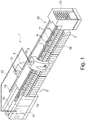
- the Figure 1 shows a textile machine producing cross-wound bobbins, in the exemplary embodiment an open-end spinning machine 1, which has a tube delivery device which can be used in the manner according to the invention.
- an open-end spinning machine 1 between end frames on a plurality of identical work stations 2 arranged on both machine longitudinal sides of the textile machine 1.
- the workplaces are designed as self-sufficient workplaces 2, that is, the workplaces 2 are each equipped with an open-end spinning device 3, a winding device 4 and a suction nozzle 29 that can be subjected to negative pressure.
- the work stations 2 are supplied by service units 5; in the exemplary embodiment by two identically designed cleaner and changer carriages.
- the service units 5, guided on guide rails 17, 18, can be moved at least along the work stations 2 of a machine longitudinal side of the open-end spinning machine 1.
- slivers that are stored in sliver cans 6 are spun into threads, which are then wound up on the winding devices 4 of the work stations 2 to form cross-wound bobbins 7.
- the winding devices 4 are for this purpose, as in Figure 2 shown, each equipped with a bobbin frame 8 for rotatably holding an empty tube 9 or a cheese 7, a winding drum 10 for properly rotating these elements and a thread traversing device 24.
- the open-end spinning machine 1 also has a central control unit 11 which is connected via a bus system 12 both to the control devices 19 of the service units 5 and to the control devices 13 of the work stations 2.
- such open-end spinning machines 1 have a cross-bobbin transport device 14 for disposing of finished cross-wound bobbins 7 and a tube delivery device 30, which essentially consists of a central tube magazine 15 arranged at the end of the machine and tube conveyor belts 16.
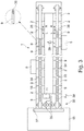
- the tube conveyor belts 16 can during the spinning / winding operation of the open-end spinning machine 1, as in FIG Figure 3 also function as a tube store 34, that is, a plurality of empty tubes 9 can be constantly stored on the tube conveyor belts 16 during the spinning / winding operation of the open-end spinning machine 1.
- the cleaner and changer trolleys 5 are, as in Figure 2 shown schematically and z. B. in the DE 44 43 818 B4 described in relative detail, each on guide rails 17, 18, which are arranged at or on the open-end spinning machine 1, can be moved along the work stations 2 and, if necessary, positioned at one of the work stations 2.
- the cleaner and changer trolleys 5 each have different handling devices that enable the service units to clean a work station if necessary or to carry out a cross-wound bobbin / empty tube change at a work station 2.
- Such service units 5 are, for example, with a highly schematically illustrated device 21 for cleaning the open-end spinning devices 3, an auxiliary thread delivery device 22 for providing a piecing thread 25, a pivotably mounted thread delivery tube 28 and with a thread application and thread transfer device 23 equipped, among other things, via a so-called (not shown) bobbin frame opener has.
- the auxiliary thread delivery device 22 is preferably equipped with a supply spool 27 and a thread delivery mechanism 26 which, if necessary, pulls the piecing thread 25 from the supply spool 27.
- the tube gripper 20 is designed in such a way that it properly receives from the tube conveyor belt 16 an empty tube 9 that is ready or delivered on the tube conveyor belt 16, regardless of the transport direction R or L in which the empty tube 9 is delivered Can transfer the coil frame 8 of the job 2.
- the cleaner and changer trolley 5 is advantageously also equipped with a tube detection device 31, which is arranged, for example, in the area of the gripping device of the tube gripper 20.
- the tube detection device 31 is adapted to the design of the empty tubes 9 that are to be identified, for. B. designed as a color sensor or as an RFID reader.
- Figure 3 shows a schematic plan view of an open-end spinning machine 1, which has a plurality of identical, preferably self-sufficient work stations 2 and which is equipped with a tube delivery device 30, the tube conveyor belts 16 of which during the Spinning / winding operation of the open-end spinning machine 1 can also function as a tube store 34.
- the tube delivery device 30 has a tube magazine 15 arranged at the end of the machine with a tube distribution device 37 and two machine-length tube conveyor belts 16 which can be driven reversibly or reversibly by means of electric drives 35.
- the electric drives 35 for example stepping motors, are connected to the central control unit 11 of the open-end spinning machine 1.
- the tube conveyor belts 16 can also function as tube storage 34 during the spinning / winding operation of the textile machine, which means that the tube conveyor belts 16 loaded with a large number of empty tubes 9 can be reversible either as required, as indicated by the double arrows 38 Running direction R or drivable in running direction L, so that empty tubes 9 stored on them can be conveyed in the shortest possible time, regardless of the location of a requesting job 2.
- the associated service unit 5 is also positioned at the relevant work station 2 and changes the present or delivered empty tube 9 into the reel frame 8 of the work station 2.
- the tube conveyor belts 16 of the tube delivery device 30 are first loaded with a large number of empty tubes 9 of the yarn section that are on the work stations 2 of the respective Long side of the machine is being processed or is to be processed soon.
- the service unit 5 transfers the completed cheese 7 to the cheese transport device 14 of the open-end spinning machine 1 by means of an ejector and drive arm.
- the tube conveyor belt 16 equipped with a large number of empty tubes 9 is controlled in such a way that a new empty tube 9 is conveyed to the relevant work station 2 as quickly as possible.
- the service unit 5 stops with its tube gripper 20, regardless of the delivery direction, then the tube gripper 20 takes the empty tube 9 from the tube conveyor belt 16, on which there are usually numerous other empty tubes 9, and changes them into the reel frame 8 of the work station 2.
- an auxiliary thread delivery device 22 of the cleaner and changer carriage 5 provides a piecing thread 25 which is fed by a thread delivery mechanism 26 from a supply bobbin 27 is withdrawn and pneumatically transferred via a pivotably mounted delivery pipe 28 into the area of a workstation's own suction nozzle 29 which sucks in the thread end.
- the delivery tube 28 then conveys the piecing thread 25 into the area of the thread laying and threading device 23, which in turn brings the piecing thread 25 into the area of the empty tube 9 held in the bobbin frame 8 of a work station 2.
- the piecing process is then started by means of the prepared piecing thread 25 and the spinning thread freshly produced in the open-end spinning device 3 is applied to the empty tube 9 held in the bobbin frame 8 and subjected to rotation by the winding drum 10.
Landscapes
- Spinning Or Twisting Of Yarns (AREA)
- Replacing, Conveying, And Pick-Finding For Filamentary Materials (AREA)
Applications Claiming Priority (1)
| Application Number | Priority Date | Filing Date | Title |
|---|---|---|---|
| DE102020108339.4A DE102020108339A1 (de) | 2020-03-26 | 2020-03-26 | Kreuzspulen herstellende Textilmaschine bzw. Verfahren zum Betreiben einer Kreuzspulen herstellenden Textilmaschine |
Publications (2)
| Publication Number | Publication Date |
|---|---|
| EP3885298A1 true EP3885298A1 (fr) | 2021-09-29 |
| EP3885298B1 EP3885298B1 (fr) | 2024-03-20 |
Family
ID=75203092
Family Applications (1)
| Application Number | Title | Priority Date | Filing Date |
|---|---|---|---|
| EP21164438.0A Active EP3885298B1 (fr) | 2020-03-26 | 2021-03-24 | Machine textile fabriquant des bobines croisées et procédé de fonctionnement d'une machine textile fabriquant des bobines croisées |
Country Status (4)
| Country | Link |
|---|---|
| US (1) | US11873185B2 (fr) |
| EP (1) | EP3885298B1 (fr) |
| CN (1) | CN113443524B (fr) |
| DE (1) | DE102020108339A1 (fr) |
Families Citing this family (2)
| Publication number | Priority date | Publication date | Assignee | Title |
|---|---|---|---|---|
| CN113911846B (zh) * | 2021-11-11 | 2023-05-09 | 浙江精功机器人智能装备有限公司 | 一种基于agv小车的智能纺织生产系统 |
| DE102022101155A1 (de) | 2022-01-19 | 2023-07-20 | Maschinenfabrik Rieter Ag | Verfahren an einer Spinnmaschine sowie Spinnmaschine |
Citations (9)
| Publication number | Priority date | Publication date | Assignee | Title |
|---|---|---|---|---|
| DE2816418A1 (de) | 1978-04-15 | 1979-10-25 | Fritz Stahlecker | Offenend-spinnmaschine mit einer spulenwechseleinrichtung |
| EP0593808A1 (fr) | 1992-10-22 | 1994-04-27 | W. SCHLAFHORST AG & CO. | Dispositif pour transporter des bobines et/ou des tubes de bobine qui sont obtenue ou qui vont être traités par des machines textiles |
| DE4402143A1 (de) | 1993-04-24 | 1994-10-27 | Schlafhorst & Co W | Vorrichtung zum Ent- und Versorgen einer Kreuzspulen herstellenden Maschine |
| DE19905856A1 (de) | 1999-02-12 | 2000-08-17 | Schlafhorst & Co W | Hülsenliefereinrichtung für eine Kreuzspulen herstellende Textilmaschine |
| DE4443818B4 (de) | 1994-12-09 | 2005-08-18 | Saurer Gmbh & Co. Kg | Kreuzspulen herstellende Textilmaschine |
| DE102007057921A1 (de) | 2007-12-01 | 2009-06-04 | Oerlikon Textile Gmbh & Co. Kg | Verfahren und Vorrichtung zum automatisierten Identifizieren von Spulenhülsen |
| DE102004012254B4 (de) | 2004-03-12 | 2014-04-17 | Rieter Ingolstadt Gmbh | Verfahren und Vorrichtung zur Bereitstellung von Leerhülsen |
| EP3382072A1 (fr) * | 2017-03-28 | 2018-10-03 | Maschinenfabrik Rieter AG | Procédé de fourniture de dispositifs de bobine croisée d'un métier à filer à douilles et métier à filer |
| DE102017129700A1 (de) | 2017-12-13 | 2019-06-13 | Saurer Spinning Solutions Gmbh & Co. Kg | Verfahren zum Betreiben eines Serviceaggregates |
Family Cites Families (8)
| Publication number | Priority date | Publication date | Assignee | Title |
|---|---|---|---|---|
| DE4222723A1 (de) | 1992-07-10 | 1994-01-13 | Schlafhorst & Co W | Vorrichtung zur Handhabung von Kreuzspulen |
| DE4338552C2 (de) * | 1993-11-11 | 2002-08-01 | Schlafhorst & Co W | Kreuzspulen herstellende Textilmaschine mit einer Vielzahl von in Reihe angeordneten Spulstellen |
| DE19739557A1 (de) | 1997-09-09 | 1999-03-11 | Rieter Ag Maschf | Transporteinrichtung für Spinnmaschine |
| DE10008036A1 (de) | 1999-02-24 | 2000-08-31 | Barmag Barmer Maschf | Vorrichtung zum Entladen mehrerer Spulen |
| WO2006031199A1 (fr) * | 2004-09-17 | 2006-03-23 | Alex Poh Teck Choong | Système et procédé de conversion en lots d’une étiquette rfid en label rfid |
| DE102010049432A1 (de) * | 2010-10-23 | 2012-04-26 | Oerlikon Textile Gmbh & Co. Kg | Hülsengreifer für ein Kreuzspulenwechselaggregat |
| DE102014001626A1 (de) | 2014-02-07 | 2015-08-13 | Saurer Germany Gmbh & Co. Kg | Kreuzspulen herstellende Textilmaschine und Verfahren zum Betreiben der Textilmaschine |
| DE102017106319A1 (de) * | 2017-03-23 | 2018-09-27 | Maschinenfabrik Rieter Ag | Spinnereimaschine sowie ein Verfahren zum Betreiben von Hülsentransportvorrichtungen an einer Spinnereimaschine |
-
2020
- 2020-03-26 DE DE102020108339.4A patent/DE102020108339A1/de active Pending
-
2021
- 2021-03-24 US US17/211,555 patent/US11873185B2/en active Active
- 2021-03-24 CN CN202110314536.0A patent/CN113443524B/zh active Active
- 2021-03-24 EP EP21164438.0A patent/EP3885298B1/fr active Active
Patent Citations (9)
| Publication number | Priority date | Publication date | Assignee | Title |
|---|---|---|---|---|
| DE2816418A1 (de) | 1978-04-15 | 1979-10-25 | Fritz Stahlecker | Offenend-spinnmaschine mit einer spulenwechseleinrichtung |
| EP0593808A1 (fr) | 1992-10-22 | 1994-04-27 | W. SCHLAFHORST AG & CO. | Dispositif pour transporter des bobines et/ou des tubes de bobine qui sont obtenue ou qui vont être traités par des machines textiles |
| DE4402143A1 (de) | 1993-04-24 | 1994-10-27 | Schlafhorst & Co W | Vorrichtung zum Ent- und Versorgen einer Kreuzspulen herstellenden Maschine |
| DE4443818B4 (de) | 1994-12-09 | 2005-08-18 | Saurer Gmbh & Co. Kg | Kreuzspulen herstellende Textilmaschine |
| DE19905856A1 (de) | 1999-02-12 | 2000-08-17 | Schlafhorst & Co W | Hülsenliefereinrichtung für eine Kreuzspulen herstellende Textilmaschine |
| DE102004012254B4 (de) | 2004-03-12 | 2014-04-17 | Rieter Ingolstadt Gmbh | Verfahren und Vorrichtung zur Bereitstellung von Leerhülsen |
| DE102007057921A1 (de) | 2007-12-01 | 2009-06-04 | Oerlikon Textile Gmbh & Co. Kg | Verfahren und Vorrichtung zum automatisierten Identifizieren von Spulenhülsen |
| EP3382072A1 (fr) * | 2017-03-28 | 2018-10-03 | Maschinenfabrik Rieter AG | Procédé de fourniture de dispositifs de bobine croisée d'un métier à filer à douilles et métier à filer |
| DE102017129700A1 (de) | 2017-12-13 | 2019-06-13 | Saurer Spinning Solutions Gmbh & Co. Kg | Verfahren zum Betreiben eines Serviceaggregates |
Also Published As
| Publication number | Publication date |
|---|---|
| US20210300717A1 (en) | 2021-09-30 |
| CN113443524B (zh) | 2023-02-28 |
| US11873185B2 (en) | 2024-01-16 |
| DE102020108339A1 (de) | 2021-09-30 |
| CN113443524A (zh) | 2021-09-28 |
| EP3885298B1 (fr) | 2024-03-20 |
Similar Documents
| Publication | Publication Date | Title |
|---|---|---|
| EP1428783B1 (fr) | Méthode et dispositif de mise en service d'un poste de travail d'une machine textile pour la fabrication de bobines à spires croisées | |
| EP3498896B1 (fr) | Procédé de fonctionnement d'un module de service | |
| EP0402630A2 (fr) | Bobinoir automatique avec un système de transport de canettes et de tubes avec plusieurs boucles de transport | |
| DE102007056561A1 (de) | Kreuzspulen herstellende Textilmaschine | |
| EP3885298B1 (fr) | Machine textile fabriquant des bobines croisées et procédé de fonctionnement d'une machine textile fabriquant des bobines croisées | |
| CH589560A5 (fr) | ||
| EP0531754A1 (fr) | Dispositif pour la distribution de pots | |
| DE4324039A1 (de) | Transportsystem an einer Topfspinnmaschine | |
| EP0392249B1 (fr) | Système d'information dans une connexion entre un ou plusieurs métiers à filer ou machines de bobinage | |
| EP2388224A2 (fr) | Agrégat de commande | |
| EP0979791A2 (fr) | Machine textile fabricant des bobines croisées | |
| EP1127831B1 (fr) | Dispositif de mise en service d'un poste de travail d'une machine textile pour la fabrication de bobines à spires croisées | |
| DE19905856B4 (de) | Hülsenliefereinrichtung für eine Kreuzspulen herstellende Textilmaschine | |
| DE19855126A1 (de) | Kreuzspulautomat sowie Verfahren zum Betreiben eines Kreuzspulautomaten | |
| DE102019110294A1 (de) | Hülsenspeicher- und -transporteinrichtung für eine Kreuzspulen herstellende Textilmaschine | |
| EP3670409A1 (fr) | Machine textile fabriquant des bobines croisées dotée d'un dispositif de transport des bobines croisées | |
| DE3800186A1 (de) | Verfahren zur belieferung des bedienungswerkes einer textilmaschine mit leeren spulhuelsen, sowie vorrichtung zum durchfuehren dieses verfahrens | |
| DE4233819C2 (de) | Verfahren zum Betreiben einer automatischen Spulmaschine bei Partiewechsel | |
| DE4328033A1 (de) | Kreuzspulen herstellende Textilmaschine | |
| DE3636654A1 (de) | Vorrichtung und verfahren zum automatischen abnehmen fertig gesponnener kopse von einer ringspinnmaschine | |
| EP4021835B1 (fr) | Dispositif d'alimentation en tubes destiné à une machine textile qui produit des bobines croisées | |
| DE102018132459A1 (de) | Kreuzspulen herstellende Textilmaschine mit einer Kreuzspulentransporteinrichtung | |
| WO2020136055A1 (fr) | Dispositif de fourniture de douilles de bobine | |
| DE4407110A1 (de) | Verfahren und Vorrichtung zum Füllen von Kannen mit länglichem Querschnitt (Flachkannen) an einer Spinnereimaschine, z. B. Strecke | |
| EP4034487B1 (fr) | Procédé pour faire fonctionner une machine textile produisant des bobines croisées et machine textile produisant des bobines croisées |
Legal Events
| Date | Code | Title | Description |
|---|---|---|---|
| PUAI | Public reference made under article 153(3) epc to a published international application that has entered the european phase |
Free format text: ORIGINAL CODE: 0009012 |
|
| STAA | Information on the status of an ep patent application or granted ep patent |
Free format text: STATUS: THE APPLICATION HAS BEEN PUBLISHED |
|
| AK | Designated contracting states |
Kind code of ref document: A1 Designated state(s): AL AT BE BG CH CY CZ DE DK EE ES FI FR GB GR HR HU IE IS IT LI LT LU LV MC MK MT NL NO PL PT RO RS SE SI SK SM TR |
|
| STAA | Information on the status of an ep patent application or granted ep patent |
Free format text: STATUS: REQUEST FOR EXAMINATION WAS MADE |
|
| 17P | Request for examination filed |
Effective date: 20220329 |
|
| RBV | Designated contracting states (corrected) |
Designated state(s): AL AT BE BG CH CY CZ DE DK EE ES FI FR GB GR HR HU IE IS IT LI LT LU LV MC MK MT NL NO PL PT RO RS SE SI SK SM TR |
|
| GRAP | Despatch of communication of intention to grant a patent |
Free format text: ORIGINAL CODE: EPIDOSNIGR1 |
|
| STAA | Information on the status of an ep patent application or granted ep patent |
Free format text: STATUS: GRANT OF PATENT IS INTENDED |
|
| INTG | Intention to grant announced |
Effective date: 20231116 |
|
| GRAS | Grant fee paid |
Free format text: ORIGINAL CODE: EPIDOSNIGR3 |
|
| GRAA | (expected) grant |
Free format text: ORIGINAL CODE: 0009210 |
|
| STAA | Information on the status of an ep patent application or granted ep patent |
Free format text: STATUS: THE PATENT HAS BEEN GRANTED |
|
| AK | Designated contracting states |
Kind code of ref document: B1 Designated state(s): AL AT BE BG CH CY CZ DE DK EE ES FI FR GB GR HR HU IE IS IT LI LT LU LV MC MK MT NL NO PL PT RO RS SE SI SK SM TR |
|
| REG | Reference to a national code |
Ref country code: GB Ref legal event code: FG4D Free format text: NOT ENGLISH |
|
| REG | Reference to a national code |
Ref country code: CH Ref legal event code: EP |
|
| REG | Reference to a national code |
Ref country code: IE Ref legal event code: FG4D Free format text: LANGUAGE OF EP DOCUMENT: GERMAN |
|
| REG | Reference to a national code |
Ref country code: DE Ref legal event code: R096 Ref document number: 502021003005 Country of ref document: DE |