EP3885298A1 - Textile machine producing cross-wound bobbins and method for operating a textile machine for creating cross-wound bobbins - Google Patents
Textile machine producing cross-wound bobbins and method for operating a textile machine for creating cross-wound bobbins Download PDFInfo
- Publication number
- EP3885298A1 EP3885298A1 EP21164438.0A EP21164438A EP3885298A1 EP 3885298 A1 EP3885298 A1 EP 3885298A1 EP 21164438 A EP21164438 A EP 21164438A EP 3885298 A1 EP3885298 A1 EP 3885298A1
- Authority
- EP
- European Patent Office
- Prior art keywords
- tube
- textile machine
- conveyor belt
- wound bobbins
- empty
- Prior art date
- Legal status (The legal status is an assumption and is not a legal conclusion. Google has not performed a legal analysis and makes no representation as to the accuracy of the status listed.)
- Granted
Links
- 239000004753 textile Substances 0.000 title claims abstract description 63
- 238000000034 method Methods 0.000 title claims description 17
- 238000004804 winding Methods 0.000 claims abstract description 32
- 235000013351 cheese Nutrition 0.000 claims abstract description 22
- 230000002441 reversible effect Effects 0.000 claims abstract description 6
- 238000001514 detection method Methods 0.000 claims description 6
- 238000012546 transfer Methods 0.000 claims description 6
- 238000007383 open-end spinning Methods 0.000 description 41
- 238000009987 spinning Methods 0.000 description 14
- 230000008859 change Effects 0.000 description 9
- 238000004140 cleaning Methods 0.000 description 7
- 238000003860 storage Methods 0.000 description 6
- 230000006870 function Effects 0.000 description 5
- 230000008569 process Effects 0.000 description 4
- 238000013461 design Methods 0.000 description 3
- 240000002129 Malva sylvestris Species 0.000 description 2
- 235000006770 Malva sylvestris Nutrition 0.000 description 2
- 230000008901 benefit Effects 0.000 description 2
- 238000009826 distribution Methods 0.000 description 2
- 230000007246 mechanism Effects 0.000 description 2
- 238000012545 processing Methods 0.000 description 2
- 230000009471 action Effects 0.000 description 1
- 230000003213 activating effect Effects 0.000 description 1
- 238000010042 air jet spinning Methods 0.000 description 1
- 230000000903 blocking effect Effects 0.000 description 1
- 239000000969 carrier Substances 0.000 description 1
- 239000003086 colorant Substances 0.000 description 1
- 238000004040 coloring Methods 0.000 description 1
- 239000002131 composite material Substances 0.000 description 1
- 230000004069 differentiation Effects 0.000 description 1
- 230000000694 effects Effects 0.000 description 1
- 238000011156 evaluation Methods 0.000 description 1
- 238000011089 mechanical engineering Methods 0.000 description 1
- 230000008092 positive effect Effects 0.000 description 1
Images

Classifications
-
- B—PERFORMING OPERATIONS; TRANSPORTING
- B65—CONVEYING; PACKING; STORING; HANDLING THIN OR FILAMENTARY MATERIAL
- B65H—HANDLING THIN OR FILAMENTARY MATERIAL, e.g. SHEETS, WEBS, CABLES
- B65H67/00—Replacing or removing cores, receptacles, or completed packages at paying-out, winding, or depositing stations
- B65H67/06—Supplying cores, receptacles, or packages to, or transporting from, winding or depositing stations
- B65H67/068—Supplying or transporting empty cores
-
- B—PERFORMING OPERATIONS; TRANSPORTING
- B65—CONVEYING; PACKING; STORING; HANDLING THIN OR FILAMENTARY MATERIAL
- B65H—HANDLING THIN OR FILAMENTARY MATERIAL, e.g. SHEETS, WEBS, CABLES
- B65H51/00—Forwarding filamentary material
- B65H51/16—Devices for entraining material by flow of liquids or gases, e.g. air-blast devices
-
- B—PERFORMING OPERATIONS; TRANSPORTING
- B65—CONVEYING; PACKING; STORING; HANDLING THIN OR FILAMENTARY MATERIAL
- B65H—HANDLING THIN OR FILAMENTARY MATERIAL, e.g. SHEETS, WEBS, CABLES
- B65H67/00—Replacing or removing cores, receptacles, or completed packages at paying-out, winding, or depositing stations
- B65H67/04—Arrangements for removing completed take-up packages and or replacing by cores, formers, or empty receptacles at winding or depositing stations; Transferring material between adjacent full and empty take-up elements
- B65H67/0405—Arrangements for removing completed take-up packages or for loading an empty core
- B65H67/0417—Arrangements for removing completed take-up packages or for loading an empty core for loading an empty core
-
- B—PERFORMING OPERATIONS; TRANSPORTING
- B65—CONVEYING; PACKING; STORING; HANDLING THIN OR FILAMENTARY MATERIAL
- B65H—HANDLING THIN OR FILAMENTARY MATERIAL, e.g. SHEETS, WEBS, CABLES
- B65H67/00—Replacing or removing cores, receptacles, or completed packages at paying-out, winding, or depositing stations
- B65H67/06—Supplying cores, receptacles, or packages to, or transporting from, winding or depositing stations
- B65H67/063—Marking or identifying devices for packages
-
- B—PERFORMING OPERATIONS; TRANSPORTING
- B65—CONVEYING; PACKING; STORING; HANDLING THIN OR FILAMENTARY MATERIAL
- B65H—HANDLING THIN OR FILAMENTARY MATERIAL, e.g. SHEETS, WEBS, CABLES
- B65H67/00—Replacing or removing cores, receptacles, or completed packages at paying-out, winding, or depositing stations
- B65H67/06—Supplying cores, receptacles, or packages to, or transporting from, winding or depositing stations
- B65H67/064—Supplying or transporting cross-wound packages, also combined with transporting the empty core
-
- B—PERFORMING OPERATIONS; TRANSPORTING
- B65—CONVEYING; PACKING; STORING; HANDLING THIN OR FILAMENTARY MATERIAL
- B65H—HANDLING THIN OR FILAMENTARY MATERIAL, e.g. SHEETS, WEBS, CABLES
- B65H67/00—Replacing or removing cores, receptacles, or completed packages at paying-out, winding, or depositing stations
- B65H67/08—Automatic end-finding and material-interconnecting arrangements
-
- B—PERFORMING OPERATIONS; TRANSPORTING
- B65—CONVEYING; PACKING; STORING; HANDLING THIN OR FILAMENTARY MATERIAL
- B65H—HANDLING THIN OR FILAMENTARY MATERIAL, e.g. SHEETS, WEBS, CABLES
- B65H2701/00—Handled material; Storage means
- B65H2701/30—Handled filamentary material
- B65H2701/31—Textiles threads or artificial strands of filaments
Definitions
- the invention relates to a textile machine producing cross-wound bobbins with a large number of identical workstations, which are arranged in the area of the machine longitudinal sides of the textile machine and each have a winding device, and with a tube delivery device, which has a central tube magazine, preferably arranged at the end of the machine, and at least one in the area of the machine longitudinal sides comprises installed tube conveyor belt, wherein on the textile machine producing cross-wound bobbins preferably at least one service unit is movably arranged, which, if necessary, a cross-wound bobbin, the z. B.
- the tube delivery device is designed so that the at least one tube conveyor belt can be used as a tube store for empty tubes during the operation of the textile machine producing cross-wound bobbins, or a method for operating such a textile machine.
- an open-end rotor spinning machine which has two rows of work stations running in the longitudinal direction of the machine and a transport device for cross-wound bobbins and / or empty tubes arranged between the rows of work stations.
- the transport device consists of a large number of interconnected, revolving individual transport elements, each of which has a transport surface for transporting a cross-wound bobbin completed at the work stations or an empty tube required at the work stations.
- a comparable transport device which is also arranged between the rows of workstations of an open-end rotor spinning machine, is also in the DE 44 43 818 B4 described.
- this known transport device is designed in such a way that a cheese and an empty tube can be conveyed on it at the same time.
- open-end rotor spinning machines which have a transport device for transporting away finished cross-wound bobbins and a separate tube delivery device for providing fresh empty tubes.
- the tube delivery device comprises a tube magazine arranged at the end of the machine and two machine-length tube conveyor belts arranged on the longitudinal sides of the textile machine above the work stations.
- the workplaces of such open-end rotor spinning machines are supplied by an automatically operating service unit which, among other things, has a memory for an empty tube.
- the service unit requests a new empty tube from the tube magazine after a cheese / empty tube change, which tube is then delivered via one of the tube conveyor belts.
- the service units of such open-end spinning machines can also have various embodiments.
- service units have been known for a long time which are designed as so-called piecing wagons. Such service units are particularly active when a job has to be re-spun after a thread break. Such service units are, however, also active when a package change / empty tube change is pending at one of the work stations.
- the known service units accordingly have various devices that are used either in connection with the re-piecing of a job or when changing cross-wound bobbins / empty tubes.
- the service units of open-end spinning machines can also, for example, in the DE 10 2017 129 700 A1 described, be designed as a cleaner and changer trolley.
- Such cleaning and changer trolleys are usually used in open-end spinning machines that have largely self-sufficient workplaces.
- largely autarkic jobs have, in addition to an open-end spinning device for producing a thread and a winding device for making a cheese, further functional elements that enable the jobs to automatically start again immediately after a thread break.
- self-sufficient workplaces only need the help of a mobile service unit when there is a job has to be cleaned, or if a package / empty tube change is due at one of the workstations, which also requires a new piecing thread.
- the cleaner and changer trolley which has meanwhile transferred the finished cheese from the package frame of the respective work station to a machine-length cheese transport device of the textile machine, waits for the requested empty tube and changes it into the coil frame of the work station upon receipt.
- the cleaner and changer trolley has a tube gripper with which the delivered empty tube can be removed from the tube transport track and placed in the bobbin frame of the work station.
- the cleaner and changer trolley then ensures that the open-end spinning device of the work site is re-spun using a so-called auxiliary thread and that the thread freshly made in the open-end spinning device is placed on the empty tube that was previously replaced in the bobbin frame.
- the pure transport time of an empty tube is often relatively long, for example, because the requesting job is located relatively far away from the tube magazine, which is often the case because it is useful in the sense of a high economic efficiency of such textile machines that The number of jobs per open-end rotor spinning machine should be selected as large as possible.
- Another disadvantage of the known method is that the efficiency of such textile machines is usually considerably reduced when a yarn section runs out in a block on a textile machine producing cross-wound bobbins, ie. i.e. if z. B. all jobs on a longitudinal side of the machine are finished at the same time and want to restart accordingly at the same time. Since the tube supply takes significantly longer than the cleaner and changer trolley needs to process the workplaces, unnecessary waiting times occur. As already indicated above, such waiting times have an overall negative effect on the efficiency of such open-end spinning machines.
- the DE 28 16 418 A1 discloses a tube conveyor belt running around a spinning machine, which can store empty tubes. This is to avoid a time delay in the delivery of empty tubes to the spinning stations. Nevertheless, in the worst case, especially when changing a lot, an empty tube has to be transported around the entire textile machine once.
- the concept leads to very long conveyor belts, since the conveyor belt must be at least twice the machine length. Due to the stretching of the conveyor belt during operation, the greater the length of the conveyor belt, the worse the accuracy of the positioning of the sleeves in front of the spinning stations.
- sensor devices are often used in such composite systems, which are designed, for example, as color sensors.
- color sensors can distinguish up to eight different sleeve colors.
- the use of such color sensors has proven itself in practice in connection with reusable, single-colored roving tubes or reusable, single-colored spinning-head tubes.
- Such color sensors cannot, however, be used when it comes to differentiating sleeves that are not embodied in a monochrome multi-color, but rather have other characteristic features.
- Such "disposable" sleeves which are usually made of cardboard at low cost, have, for example, a pattern on the surface of the sleeve or a specific print which identifies a specific thread section.
- a method and apparatus for identifying such "disposable" sleeves is e.g. B. in the DE 10 2007 057 921 A1 described.
- the known device has a CCD camera for creating an image of the bobbin and a light source, a digital image processing device being connected to the CCD camera.
- the image processing device the image of the bobbin tube to be identified is checked for characteristic features and compared with images of already classified bobbin tubes that are stored in a memory. If the characteristic features of the image of the bobbin case match one of the images of an already classified bobbin case, the bobbin case to be checked is deemed to have been identified.
- transponders it is z. B. by the EP 0 593 808 A1 known to arrange identification markings in the form of electronic information carriers, so-called transponders, on textile spools or their sleeves. These intrinsically passive electronic transponders can be activated electromagnetically via sensor devices to emit an individual identifier, which is read into a storage and evaluation unit.
- the invention is based on the object of further improving the known tube delivery devices, in particular the aim of the a textile machine producing cheeses, when changing cheeses / empty tubes and / or changing yarn batches, tube delivery times can be minimized.
- this object is achieved in that a drive is connected to the at least one tube conveyor belt which enables the tube conveyor belt to operate in a reversible manner.
- the invention can in principle be applied to all textile machines producing cross-wound bobbins. These are in particular open-end spinning machines, e.g. B. rotor spinning machine and air-jet spinning machine, but also winding machines.
- open-end spinning machines e.g. B. rotor spinning machine and air-jet spinning machine, but also winding machines.
- the inventive design and use of the tube conveyor belt or the tube conveyor belts of the tube delivery device of the textile machine producing cross-wound bobbins has the advantage that the transport routes of the empty tubes to the work stations are greatly shortened in this way.
- This means that the tube conveyor belts can be controlled in such a way that one of the empty tubes stored on the tube conveyor belts can immediately be transferred quickly and as required to a requesting work station and inserted there into the bobbin frame of the work station in question by a movable service unit positioned at the work station or by facilities at the work station can be.
- the simultaneous function of the tube conveyor belts as a transport and storage device ensures a quick and reliable supply of the workplaces with empty tubes in a simple manner, which has a very positive effect on the efficiency of the textile machine producing cross-wound bobbins.
- drives are connected to the tube conveyor belts which enable the tube conveyor belts to be operated in a reversible and precise manner. In this way it is ensured that the delivery path of the empty tubes is optimized and thus the delivery times of the empty tubes that occur during the operation of the textile machine are very short for all workplaces of the textile machine.
- Means for blocking the empty tubes are preferably assigned to a tube conveyor belt. As a result, only the empty tube is to be blocked, whereas the tube conveyor belt continues to be driven. In this way, gaps on the tube conveyor belt that arise when empty tubes are removed from the tube conveyor belt for changing into the winding device of a work station can be closed again.
- These means are preferably arranged at one end of the tube conveyor belt. When an empty tube has reached the end of the tube conveyor belt, the tube conveyor belt is first driven further in the corresponding direction. This pushes the empty tubes together on the tube conveyor belt and closes any gaps. Then there are free positions for empty tubes at the other end of the tube conveyor belt. By reversing the drive of the tube conveyor belt, the free positions can then be filled again by a central tube magazine preferably arranged at the other end of the tube conveyor belt.
- the drives are preferably designed as stepper motors, since such stepper motors are tried and tested, inexpensive mass-produced components.
- stepper motors are also relatively uncomplicated in terms of their control and can therefore be implemented inexpensively.
- a plurality of empty tubes can be stored on the tube conveyor belt or the tube conveyor belts of the tube delivery device during operation of the textile machine.
- Workplaces are preferably arranged on both machine longitudinal sides of the textile machine.
- the empty tubes stored on one of the tube conveyor belts are designed identically if all the work stations on the associated longitudinal side of the machine produce the same yarn section. That is, if on all work stations of a machine longitudinal side of a textile machine producing cross-wound bobbins, bobbins of the same yarn section are produced, only empty tubes of the type required for this yarn section are located on the associated tube conveyor belt.
- These identical empty tubes stored on the tube conveyor belt are stored by the service unit or the work stations for sure recognized and, if necessary, can be quickly fed to each of the work stations on this longitudinal side of the machine.
- Such a party-specific identification of the empty tubes can be made, for example, by a specific coloring of the empty tubes, or by virtue of the fact that the empty tubes have a special pattern.
- the empty tubes are each equipped with an RFID transponder which has a party-specific identifier. Using the identification of such RFID transponders, a proper, party-specific assignment of the empty tubes is possible in a simple manner.
- the service unit or the work stations are equipped with a tube recognition device which, depending on the design or equipment of the empty tube that has to be recognized, is designed either as a color sensor or CCD camera or as an RFID reader.
- a tube recognition device which, depending on the design or equipment of the empty tube that has to be recognized, is designed either as a color sensor or CCD camera or as an RFID reader.
- Such tube detection devices are known both in general mechanical engineering and in the textile machine industry and are in use in practice.
- the service unit or the work stations also preferably have a tube gripper which is designed so that it can properly pick up an empty tube from the tube conveyor belt and transfer it into the reel frame of the winding device of a work station. That is, the tube gripper is designed in such a way that, regardless of the direction from which the empty tube is delivered by the tube conveyor belt, it can stop the empty tube, remove it from the tube conveyor belt and change it to the bobbin frame of the job in question.
- the method according to the invention for operating a textile machine producing cross-wound bobbins which is preferably operated by a service unit and has a tube delivery device with a reversible, precisely drivable tube conveyor belt, which during operation of the textile machine producing cross-wound bobbins large parts of their length can be used as tube storage for a large number of empty tubes, has the advantage that the transport routes of the individual empty tubes and thus the waiting times of the service unit or the work station can be minimized. This means that by activating a tube conveyor belt as required, empty tubes can be transferred quickly and easily to workplaces that are to be requested and placed there in the reel frame of the workplaces in question.
- the tube conveyor belt is reversed if necessary.
- the closest, matching empty tube can be supplied to the requesting work station as quickly as possible, regardless of the position of the empty tube in relation to the work place.
- the tube conveyor belt can also be reversed when the tubes have reached the end of the tube conveyor belt.
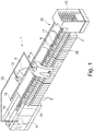
- the Figure 1 shows a textile machine producing cross-wound bobbins, in the exemplary embodiment an open-end spinning machine 1, which has a tube delivery device which can be used in the manner according to the invention.
- an open-end spinning machine 1 between end frames on a plurality of identical work stations 2 arranged on both machine longitudinal sides of the textile machine 1.
- the workplaces are designed as self-sufficient workplaces 2, that is, the workplaces 2 are each equipped with an open-end spinning device 3, a winding device 4 and a suction nozzle 29 that can be subjected to negative pressure.
- the work stations 2 are supplied by service units 5; in the exemplary embodiment by two identically designed cleaner and changer carriages.
- the service units 5, guided on guide rails 17, 18, can be moved at least along the work stations 2 of a machine longitudinal side of the open-end spinning machine 1.
- slivers that are stored in sliver cans 6 are spun into threads, which are then wound up on the winding devices 4 of the work stations 2 to form cross-wound bobbins 7.
- the winding devices 4 are for this purpose, as in Figure 2 shown, each equipped with a bobbin frame 8 for rotatably holding an empty tube 9 or a cheese 7, a winding drum 10 for properly rotating these elements and a thread traversing device 24.
- the open-end spinning machine 1 also has a central control unit 11 which is connected via a bus system 12 both to the control devices 19 of the service units 5 and to the control devices 13 of the work stations 2.
- such open-end spinning machines 1 have a cross-bobbin transport device 14 for disposing of finished cross-wound bobbins 7 and a tube delivery device 30, which essentially consists of a central tube magazine 15 arranged at the end of the machine and tube conveyor belts 16.
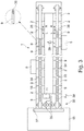
- the tube conveyor belts 16 can during the spinning / winding operation of the open-end spinning machine 1, as in FIG Figure 3 also function as a tube store 34, that is, a plurality of empty tubes 9 can be constantly stored on the tube conveyor belts 16 during the spinning / winding operation of the open-end spinning machine 1.
- the cleaner and changer trolleys 5 are, as in Figure 2 shown schematically and z. B. in the DE 44 43 818 B4 described in relative detail, each on guide rails 17, 18, which are arranged at or on the open-end spinning machine 1, can be moved along the work stations 2 and, if necessary, positioned at one of the work stations 2.
- the cleaner and changer trolleys 5 each have different handling devices that enable the service units to clean a work station if necessary or to carry out a cross-wound bobbin / empty tube change at a work station 2.
- Such service units 5 are, for example, with a highly schematically illustrated device 21 for cleaning the open-end spinning devices 3, an auxiliary thread delivery device 22 for providing a piecing thread 25, a pivotably mounted thread delivery tube 28 and with a thread application and thread transfer device 23 equipped, among other things, via a so-called (not shown) bobbin frame opener has.
- the auxiliary thread delivery device 22 is preferably equipped with a supply spool 27 and a thread delivery mechanism 26 which, if necessary, pulls the piecing thread 25 from the supply spool 27.
- the tube gripper 20 is designed in such a way that it properly receives from the tube conveyor belt 16 an empty tube 9 that is ready or delivered on the tube conveyor belt 16, regardless of the transport direction R or L in which the empty tube 9 is delivered Can transfer the coil frame 8 of the job 2.
- the cleaner and changer trolley 5 is advantageously also equipped with a tube detection device 31, which is arranged, for example, in the area of the gripping device of the tube gripper 20.
- the tube detection device 31 is adapted to the design of the empty tubes 9 that are to be identified, for. B. designed as a color sensor or as an RFID reader.
- Figure 3 shows a schematic plan view of an open-end spinning machine 1, which has a plurality of identical, preferably self-sufficient work stations 2 and which is equipped with a tube delivery device 30, the tube conveyor belts 16 of which during the Spinning / winding operation of the open-end spinning machine 1 can also function as a tube store 34.
- the tube delivery device 30 has a tube magazine 15 arranged at the end of the machine with a tube distribution device 37 and two machine-length tube conveyor belts 16 which can be driven reversibly or reversibly by means of electric drives 35.
- the electric drives 35 for example stepping motors, are connected to the central control unit 11 of the open-end spinning machine 1.
- the tube conveyor belts 16 can also function as tube storage 34 during the spinning / winding operation of the textile machine, which means that the tube conveyor belts 16 loaded with a large number of empty tubes 9 can be reversible either as required, as indicated by the double arrows 38 Running direction R or drivable in running direction L, so that empty tubes 9 stored on them can be conveyed in the shortest possible time, regardless of the location of a requesting job 2.
- the associated service unit 5 is also positioned at the relevant work station 2 and changes the present or delivered empty tube 9 into the reel frame 8 of the work station 2.
- the tube conveyor belts 16 of the tube delivery device 30 are first loaded with a large number of empty tubes 9 of the yarn section that are on the work stations 2 of the respective Long side of the machine is being processed or is to be processed soon.
- the service unit 5 transfers the completed cheese 7 to the cheese transport device 14 of the open-end spinning machine 1 by means of an ejector and drive arm.
- the tube conveyor belt 16 equipped with a large number of empty tubes 9 is controlled in such a way that a new empty tube 9 is conveyed to the relevant work station 2 as quickly as possible.
- the service unit 5 stops with its tube gripper 20, regardless of the delivery direction, then the tube gripper 20 takes the empty tube 9 from the tube conveyor belt 16, on which there are usually numerous other empty tubes 9, and changes them into the reel frame 8 of the work station 2.
- an auxiliary thread delivery device 22 of the cleaner and changer carriage 5 provides a piecing thread 25 which is fed by a thread delivery mechanism 26 from a supply bobbin 27 is withdrawn and pneumatically transferred via a pivotably mounted delivery pipe 28 into the area of a workstation's own suction nozzle 29 which sucks in the thread end.
- the delivery tube 28 then conveys the piecing thread 25 into the area of the thread laying and threading device 23, which in turn brings the piecing thread 25 into the area of the empty tube 9 held in the bobbin frame 8 of a work station 2.
- the piecing process is then started by means of the prepared piecing thread 25 and the spinning thread freshly produced in the open-end spinning device 3 is applied to the empty tube 9 held in the bobbin frame 8 and subjected to rotation by the winding drum 10.
Landscapes
- Spinning Or Twisting Of Yarns (AREA)
- Replacing, Conveying, And Pick-Finding For Filamentary Materials (AREA)
Abstract
Die Erfindung betrifft eine Kreuzspulen herstellende Textilmaschine (1) mit einer Vielzahl identischer Arbeitsstellen (2), die im Bereich der Maschinenlängsseiten der Textilmaschine (1) angeordnet sind und jeweils eine Spuleinrichtung (4) verfügen und die mit einer Hülsenliefereinrichtung (30) ausgestattet ist, welche ein zentrales Hülsenmagazin (15) und mindestens ein im Bereich der Maschinenlängsseiten installiertes Hülsentransportband (16) umfasst, wobei an der Kreuzspulen herstellenden Textilmaschine (1) im Bedarfsfall eine Kreuzspule (7) aus der Spuleinrichtung (4) der betreffenden Arbeitsstelle (2) entfernbar und auf eine maschinenlange Kreuzspulen-Transporteinrichtung (14) überführbar sowie mittels eines Hülsengreifers (20) eine Leerhülse (9), die auf dem Hülsentransportband (16) der Hülsenliefereinrichtung (30) bereitgestellt wird, in die Spuleinrichtung (4) der betroffenen Arbeitsstelle (2) einwechselbar ist. Die Hülsenliefereinrichtung (30) ist so ausgebildet, dass das Hülsentransportband (16) während des Betriebes der Kreuzspulen herstellenden Textilmaschine (1) als Hülsenspeicher (34) für Leerhülsen (9) nutzbar ist.Um den Wirkungsgrad einer solchen Kreuzspulen herstellenden Textilmaschine zu verbessern, insbesondere die bei Garnpartiewechseln an einer Kreuzspulen herstellenden Textilmaschine anfallenden Hülsenlieferzeiten deutlich zu minimieren, ist erfindungsgemäß vorgesehen, dass an das mindestens eine Hülsentransportband (16) ein Antrieb (35) angeschlossen ist, der einen reversierbaren Betrieb des Hülsentransportbandes (16) ermöglicht.The invention relates to a textile machine (1) producing cross-wound bobbins with a large number of identical work stations (2) which are arranged in the area of the longitudinal sides of the textile machine (1) and each have a winding device (4) and which is equipped with a tube delivery device (30), which comprises a central tube magazine (15) and at least one tube conveyor belt (16) installed in the area of the longitudinal sides of the machine, with a cheese (7) being removable from the winding device (4) of the relevant work station (2) on the textile machine (1) producing cheese and can be transferred to a machine-length cheese transport device (14) and, by means of a tube gripper (20), an empty tube (9), which is provided on the tube conveyor belt (16) of the tube delivery device (30), into the winding device (4) of the work station concerned (2 ) is interchangeable. The tube delivery device (30) is designed in such a way that the tube conveyor belt (16) can be used as a tube store (34) for empty tubes (9) during operation of the textile machine (1) producing cross-wound bobbins. In order to improve the efficiency of such a textile machine producing cross-wound bobbins, in particular To significantly minimize the tube delivery times that arise when changing yarn batches on a textile machine producing cheese cross-wound bobbins, the invention provides that a drive (35) is connected to the at least one tube conveyor belt (16), which enables reversible operation of the tube conveyor belt (16).
Description
Die Erfindung betrifft eine Kreuzspulen herstellende Textilmaschine mit einer Vielzahl identischer Arbeitsstellen, die im Bereich der Maschinenlängsseiten der Textilmaschine angeordnet sind und jeweils über eine Spuleinrichtung verfügen, und mit einer Hülsenliefereinrichtung, welche ein zentrales, vorzugweise maschinenendseitig angeordnetes, Hülsenmagazin und mindestens ein im Bereich der Maschinenlängsseiten installiertes Hülsentransportband umfasst, wobei an der Kreuzspulen herstellenden Textilmaschine vorzugsweise wenigstens ein Serviceaggregat verfahrbar angeordnet ist, das im Bedarfsfall eine Kreuzspule, die z. B. einen vorgegebenen Durchmesser erreicht hat, aus der Spulvorrichtung der betreffenden Arbeitsstelle entfernt und auf eine maschinenlange Kreuzspulen-Transporteinrichtung überführt sowie mittels eines Hülsengreifers eine Leerhülse, die auf einem der Hülsentransportbänder der Hülsenliefereinrichtung bereitgestellt wird, in die Spulvorrichtung der betroffenen Arbeitsstelle einwechselt, wobei die Hülsenliefereinrichtung so ausgebildet ist, dass das mindestens eine Hülsentransportband während des Betriebes der Kreuzspulen herstellenden Textilmaschine als Hülsenspeicher für Leerhülsen nutzbar ist, bzw. ein Verfahren zum Betreiben einer solchen Textilmaschine.The invention relates to a textile machine producing cross-wound bobbins with a large number of identical workstations, which are arranged in the area of the machine longitudinal sides of the textile machine and each have a winding device, and with a tube delivery device, which has a central tube magazine, preferably arranged at the end of the machine, and at least one in the area of the machine longitudinal sides comprises installed tube conveyor belt, wherein on the textile machine producing cross-wound bobbins preferably at least one service unit is movably arranged, which, if necessary, a cross-wound bobbin, the z. B. has reached a predetermined diameter, removed from the winding device of the job in question and transferred to a machine-length cross-wound bobbin transport device and, by means of a tube gripper, an empty tube, which is provided on one of the tube conveyor belts of the tube delivery device, changes into the winding device of the workplace concerned, the The tube delivery device is designed so that the at least one tube conveyor belt can be used as a tube store for empty tubes during the operation of the textile machine producing cross-wound bobbins, or a method for operating such a textile machine.
Kreuzspulen herstellende Textilmaschinen, die vorzugsweise auf beiden Maschinenlängsseiten eine Vielzahl von identischen Arbeitsstellen aufweisen und die über eine Hülsenliefereinrichtung für Leerhülsen verfügen, sind seit langem in verschiedenen Ausführungsformen bekannt und in der Patentliteratur zum Teil recht ausführlich beschrieben.Textile machines producing cross-wound bobbins, which preferably have a large number of identical workstations on both longitudinal sides of the machine and which have a tube delivery device for empty tubes, have long been known in various embodiments and are sometimes described in great detail in the patent literature.
In der
Eine vergleichbare Transporteinrichtung, die ebenfalls zwischen den Arbeitsstellenreihen einer Offenend-Rotorspinnmaschine angeordnet ist, ist auch in der
Durch die
Wie die Hülsenliefereinrichtungen können auch die Serviceaggregate solcher Offenend-Spinnmaschinen verschiedene Ausführungsformen aufweisen.Like the tube delivery devices, the service units of such open-end spinning machines can also have various embodiments.
Es sind bspw. seit langem Serviceaggregate bekannt, die als so genannte Anspinnwagen ausgebildet sind. Solche Serviceaggregate werden insbesondere dann tätig, wenn eine Arbeitsstelle nach einem Fadenbruch neu angesponnen werden muss. Derartige Serviceaggregate werden allerdings auch dann tätig, wenn an einer der Arbeitsstellen ein Kreuzspulen-/Leerhülsenwechsel ansteht. Die bekannten Serviceaggregate verfügen entsprechend über verschiedene Einrichtungen, die entweder im Zusammenhang mit dem Neuanspinnen einer Arbeitsstelle oder bei einem Kreuzspulen-/Leerhülsenwechsel zum Einsatz kommen. Die Serviceaggregate von Offenend-Spinnmaschinen können allerdings auch, wie bspw. in der
Solche Reiniger- und Wechslerwagen kommen in der Regel bei Offenend-Spinnmaschinen zum Einsatz, die über weitestgehend autarke Arbeitsstellen verfügen. Solche weitestgehend autarken Arbeitsstellen weisen, wie an sich bekannt, jeweils neben einer Offenend-Spinnvorrichtung zur Fertigung eines Fadens und einer Spulvorrichtung zur Herstellung einer Kreuzspule weitere Funktionselemente auf, die es den Arbeitsstellen ermöglichen, nach einem Fadenbruch sofort wieder selbsttätig anzuspinnen. Das heißt, autarke Arbeitsstellen benötigen die Hilfe eines fahrbaren Serviceaggregates nur dann, wenn eine Arbeitsstelle gereinigt werden muss, oder wenn an einer der Arbeitsstellen ein Kreuzspulen-/Leerhülsenwechsel ansteht, bei dem auch ein neuer Anspinnfaden benötigt wird.Such cleaning and changer trolleys are usually used in open-end spinning machines that have largely self-sufficient workplaces. As is known per se, such largely autarkic jobs have, in addition to an open-end spinning device for producing a thread and a winding device for making a cheese, further functional elements that enable the jobs to automatically start again immediately after a thread break. This means that self-sufficient workplaces only need the help of a mobile service unit when there is a job has to be cleaned, or if a package / empty tube change is due at one of the workstations, which also requires a new piecing thread.
Bei einem Kreuzspulen-/Leerhülsenwechsel, der bekanntlich dann notwendig wird, wenn an einer der Arbeitsstellen die Kreuzspule einen vorgegebenen Durchmesser erreicht hat und gegen eine neue Leerhülse ausgetauscht werden muss, wird seitens der betroffenen Arbeitsstelle ein so genannter Arbeitsauftrag abgesetzt, woraufhin der Reiniger- und Wechslerwagen zu dieser Arbeitsstelle fährt und sich vor der Arbeitsstelle positioniert. Die betroffene Arbeitsstelle fordert außerdem vom maschinenendseitig angeordneten Hülsenmagazin eine Leerhülse an, die über eine der Hülsentransportbahnen der Hülsenliefereinrichtung zum Reiniger- und Wechslerwagen bzw. zur betroffenen Arbeitsstelle transportiert wird.In the case of a cheese / empty tube change, which is known to be necessary when the cheese has reached a specified diameter at one of the workstations and has to be replaced with a new empty tube, a so-called work order is placed by the affected workstation, whereupon the cleaner and The changer trolley drives to this job and positions itself in front of the job. The affected work area also requests an empty tube from the tube magazine arranged at the end of the machine, which is transported via one of the tube transport tracks of the tube delivery device to the cleaning and changer trolley or to the affected work area.
Der Reiniger- und Wechslerwagen, der inzwischen die fertiggestellte Kreuzspule aus dem Spulenrahmen der betreffenden Arbeitsstelle auf eine maschinenlange Kreuzspulen-Transporteinrichtung der Textilmaschine überführt hat, wartet auf die angeforderte Leerhülse und wechselt diese nach Erhalt in den Spulenrahmen der Arbeitsstelle ein. Der Reiniger- und Wechslerwagen weist zu diesem Zweck einen Hülsengreifer auf, mit dem die angelieferte Leerhülse von der Hülsentransportbahn entnommen und in den Spulenrahmen der Arbeitsstelle eingelegt werden kann. Anschließend sorgt der Reiniger- und Wechslerwagen dafür, dass die Offenend-Spinnvorrichtung der Arbeitsstelle mittels eines so genannten Hilfsfadens neu angesponnen und der in der Offenend-Spinnvorrichtung frisch gefertigte Faden an die zuvor in den Spulenrahmen eingewechselte Leerhülse angelegt wird.The cleaner and changer trolley, which has meanwhile transferred the finished cheese from the package frame of the respective work station to a machine-length cheese transport device of the textile machine, waits for the requested empty tube and changes it into the coil frame of the work station upon receipt. For this purpose, the cleaner and changer trolley has a tube gripper with which the delivered empty tube can be removed from the tube transport track and placed in the bobbin frame of the work station. The cleaner and changer trolley then ensures that the open-end spinning device of the work site is re-spun using a so-called auxiliary thread and that the thread freshly made in the open-end spinning device is placed on the empty tube that was previously replaced in the bobbin frame.
Nachteilig bei diesem bekannten Verfahren ist allerdings, dass vor jeder neuen LeerhülsenAnforderung das betreffende Hülsentransportband frei sein muss, das heißt, eine neue Leerhülsenanforderung wird erst dann bearbeitet, wenn das Hülsentransportband nicht mehr durch eine noch reisende Leerhülse blockiert ist.The disadvantage of this known method, however, is that the relevant tube conveyor belt must be free before each new empty tube request, i.e. a new empty tube request is only processed when the tube conveyor belt is no longer blocked by an empty tube that is still traveling.
Außerdem ist bei dem bekannten Verfahren oft auch die reine Transportzeit einer Leerhülse verhältnismäßig lang, bspw., weil die anfordernde Arbeitsstelle relativ weit entfernt vom Hülsenmagazin angeordnet ist, was häufig der Fall ist, da es im Sinne einer hohen Wirtschaftlichkeit solcher Textilmaschinen zweckmäßig ist, die Anzahl der Arbeitsstellen pro Offenend-Rotorspinnmaschine möglichst groß zu wählen.In addition, with the known method, the pure transport time of an empty tube is often relatively long, for example, because the requesting job is located relatively far away from the tube magazine, which is often the case because it is useful in the sense of a high economic efficiency of such textile machines that The number of jobs per open-end rotor spinning machine should be selected as large as possible.
Im Ergebnis ist der Hülsendurchsatz bei diesem bekannten Verfahren oft relativ gering.As a result, the tube throughput in this known method is often relatively low.
Ein weiterer Nachteil des bekannten Verfahrens besteht darin, dass der Nutzeffekt derartiger Textilmaschinen in der Regel erheblich sinkt, wenn an einer Kreuzspulen herstellenden Textilmaschine eine Garnpartie im Block ausläuft, d. h., wenn z. B. alle Arbeitsstellen einer Maschinenlängsseite gleichzeitig fertig werden und entsprechend gleichzeitig wieder neu starten wollen. Da die Hülsenversorgung deutlich länger dauert, als der Reiniger- und Wechslerwagen für die Bearbeitung der Arbeitsstellen benötigt, treten unnötige Wartezeiten auf. Wie vorsteht bereits angedeutet, wirken sich solche Wartezeiten insgesamt negativ auf den Wirkungsgrad derartiger Offenend-Spinnmaschinen aus.Another disadvantage of the known method is that the efficiency of such textile machines is usually considerably reduced when a yarn section runs out in a block on a textile machine producing cross-wound bobbins, ie. i.e. if z. B. all jobs on a longitudinal side of the machine are finished at the same time and want to restart accordingly at the same time. Since the tube supply takes significantly longer than the cleaner and changer trolley needs to process the workplaces, unnecessary waiting times occur. As already indicated above, such waiting times have an overall negative effect on the efficiency of such open-end spinning machines.
Um die Transportzeiten der Leerhülsen bei langen Kreuzspulen herstellenden Textilmaschinen zu verkürzen, ist daher in der Vergangenheit bereits ein Verfahren bzw. eine Vorrichtung entwickelt worden, das/die mit einem Zwischenspeicher arbeitet. In der
Die
In der Textilmaschinenindustrie ist es im Zusammenhang mit dem Verbund mehrerer Textilmaschinen, die im so genanntem Mehrpartien-Betrieb laufen, außerdem seit langem Stand der Technik, die unterschiedlichen Garnpartien für das Bedienpersonal durch z. B. farblich unterschiedlich gekennzeichnete Spulenhülsen erkennbar zu machen.In the textile machine industry, it has long been the state of the art in connection with the network of several textile machines that run in so-called multi-part operation, the different yarn parts for the operating personnel by z. B. to make differently colored bobbin tubes recognizable.
Es ist dabei sowohl bekannt, Vorgarnspulen durch farbige, wieder verwendbare Spulenhülsen zu kennzeichnen, als auch Spinnkopse auf farbige, ebenfalls wiederverwendbare Spinnkopshülsen zu wickeln. Solche wiederverwendbaren Hülsen sind in der Regel aus einem stabilen Kunststoff gefertigt und einfarbig eingefärbt.It is known both to identify roving bobbins by colored, reusable bobbin tubes, and to wind spinning cops onto colored, likewise reusable spinning cops. Such reusable sleeves are usually made of a stable plastic and colored in a single color.
Um während des Maschinenbetriebes automatisch eine sichere Unterscheidung solcher Hülsen zu gewährleisten, kommen bei solchen Verbundsystemen oft Sensoreinrichtungen zum Einsatz, die bspw. als Farbsensoren ausgebildet sind. Solche im Handel erhältlichen Farbsensoren können bis zu acht unterschiedliche Hülsenfarben unterscheiden. Der Einsatz derartiger Farbsensoren hat sich im Zusammenhang mit wiederverwendbaren, einfarbigen Vorgarnhülsen oder wiederverwendbaren, einfarbigen Spinnkopshülsen in der Praxis durchaus bewährt. Solche Farbsensoren sind allerdings nicht einsetzbar, wenn es darum geht, Hülsen zu unterscheiden, die nicht einfarbig bunt ausgebildet sind, sondern andere charakteristische Merkmale aufweisen. Solche, in der Regel kostengünstig aus Pappe gefertigten "Wegwerf"-Hülsen weisen bspw. auf der Hülsenoberfläche eine Musterung oder einen bestimmten Aufdruck auf, der eine bestimmte Garnpartie kennzeichnet.In order to automatically ensure a reliable differentiation of such sleeves during machine operation, sensor devices are often used in such composite systems, which are designed, for example, as color sensors. Such commercially available color sensors can distinguish up to eight different sleeve colors. The use of such color sensors has proven itself in practice in connection with reusable, single-colored roving tubes or reusable, single-colored spinning-head tubes. Such color sensors cannot, however, be used when it comes to differentiating sleeves that are not embodied in a monochrome multi-color, but rather have other characteristic features. Such "disposable" sleeves, which are usually made of cardboard at low cost, have, for example, a pattern on the surface of the sleeve or a specific print which identifies a specific thread section.
Ein Verfahren bzw. eine Vorrichtung zum Identifizieren derartiger "Wegwerf"-Hülsen ist z. B. in der
Des Weiteren ist es z. B. durch die
Ausgehend vom vorgenannten Stand der Technik liegt der Erfindung die Aufgabe zugrunde, die bekannten Hülsenliefereinrichtungen weiter zu verbessern, insbesondere sollen die an einer Kreuzspulen herstellenden Textilmaschine bei Kreuzspulen-/Leerhülsenwechseln und/oder Garnpartiewechseln anfallenden Hülsenlieferzeiten minimiert werden.Proceeding from the aforementioned prior art, the invention is based on the object of further improving the known tube delivery devices, in particular the aim of the a textile machine producing cheeses, when changing cheeses / empty tubes and / or changing yarn batches, tube delivery times can be minimized.
Diese Aufgabe wird erfindungsgemäß dadurch gelöst, dass an das mindestens eine Hülsentransportband ein Antrieb angeschlossen ist, der einen reversierbaren Betrieb des Hülsentransportbandes ermöglicht.According to the invention, this object is achieved in that a drive is connected to the at least one tube conveyor belt which enables the tube conveyor belt to operate in a reversible manner.
Vorteilhafte Ausgestaltungen der erfindungsgemäßen Vorrichtung bzw. das erfindungsgemäße Verfahren sind/ist Gegenstand der Unteransprüche.Advantageous configurations of the device according to the invention and the method according to the invention are / is the subject of the subclaims.
Die Erfindung ist prinzipiell auf alle Kreuzspulen herstellenden Textilmaschinen anwendbar. Das sind insbesondere Offenend-Spinnmaschinen, also z. B. Rotorspinnmaschine und Luftspinnmaschine, aber auch Spulmaschinen.The invention can in principle be applied to all textile machines producing cross-wound bobbins. These are in particular open-end spinning machines, e.g. B. rotor spinning machine and air-jet spinning machine, but also winding machines.
Die erfindungsgemäße Ausbildung und Nutzung des Hülsentransportbandes bzw. der Hülsentransportbänder der Hülsenliefereinrichtung der Kreuzspulen herstellenden Textilmaschine hat den Vorteil, dass auf diese Weise die Transportwege der Leerhülsen zu den Arbeitsstellen stark verkürzt werden. Das bedeutet, die Hülsentransportbänder sind so ansteuerbar, dass eine der auf den Hülsentransportbändern bevorrateten Leerhülse sofort schnell und bedarfsgerecht zu einer anfordernden Arbeitsstelle überführbar ist und dort durch ein an der Arbeitsstelle positioniertes, verfahrbares Serviceaggregat oder durch Einrichtungen der Arbeitsstelle in den Spulenrahmen der betreffenden Arbeitsstelle eingelegt werden kann.The inventive design and use of the tube conveyor belt or the tube conveyor belts of the tube delivery device of the textile machine producing cross-wound bobbins has the advantage that the transport routes of the empty tubes to the work stations are greatly shortened in this way. This means that the tube conveyor belts can be controlled in such a way that one of the empty tubes stored on the tube conveyor belts can immediately be transferred quickly and as required to a requesting work station and inserted there into the bobbin frame of the work station in question by a movable service unit positioned at the work station or by facilities at the work station can be.
Insbesondere bei Garnpartiewechseln kann durch die gleichzeitige Funktion der Hülsentransportbänder als Transport- und Speichereinrichtung auf einfache Weise eine schnelle und zuverlässige Versorgung der Arbeitsstellen mit Leerhülsen sichergestellt werden, was sich sehr positiv auf den Wirkungsgrad der Kreuzspulen herstellenden Textilmaschine auswirkt.Particularly when changing yarn batches, the simultaneous function of the tube conveyor belts as a transport and storage device ensures a quick and reliable supply of the workplaces with empty tubes in a simple manner, which has a very positive effect on the efficiency of the textile machine producing cross-wound bobbins.
Erfindungsgemäß ist vorgesehen, dass an die Hülsentransportbänder Antriebe angeschlossen sind, die einen reversierbaren und exakten Betrieb der Hülsentransportbänder ermöglichen. Auf diese Weise wird sichergestellt, dass der Lieferweg der Leerhülsen optimiert wird und somit die während des Betriebes der Textilmaschine auftretenden Lieferzeiten der Leerhülsen für alle Arbeitsstellen der Textilmaschine sehr kurz sind.According to the invention, it is provided that drives are connected to the tube conveyor belts which enable the tube conveyor belts to be operated in a reversible and precise manner. In this way it is ensured that the delivery path of the empty tubes is optimized and thus the delivery times of the empty tubes that occur during the operation of the textile machine are very short for all workplaces of the textile machine.
Vorzugsweise sind einem Hülsentransportband Mittel zur Blockierung der Leerhülsen zugeordnet. Dadurch soll nur die Leerhülse blockiert werden, wohingegen das Hülsentransportband weiter angetrieben wird. Auf diese Weise lassen sich Lücken auf dem Hülsentransportband, die durch Entnahme von Leerhülsen von dem Hülsentransportband zum Einwechseln in die Spuleinrichtung einer Arbeitsstelle entstehen, wieder schließen. Diese Mittel sind vorzugsweise an einem Ende des Hülsentransportbandes angeordnet. Wenn eine Leerhülse das Ende des Hülsentransportbandes erreicht hat, wird das Hülsentransportband zunächst weiter in die entsprechende Richtung angetrieben. Dadurch werden die Leerhülsen auf dem Hülsentransportband zusammengeschoben und Lücken geschlossen. Dann entstehen freie Positionen für Leerhülsen an dem anderen Ende des Hülsentransportbandes. Durch Reversieren des Antriebes des Hülsentransportbandes können dann die freien Positionen durch ein vorzugsweise an dem anderen Ende des Hülsentransportbandes angeordnetes zentrales Hülsenmagazin wieder befüllt werden.Means for blocking the empty tubes are preferably assigned to a tube conveyor belt. As a result, only the empty tube is to be blocked, whereas the tube conveyor belt continues to be driven. In this way, gaps on the tube conveyor belt that arise when empty tubes are removed from the tube conveyor belt for changing into the winding device of a work station can be closed again. These means are preferably arranged at one end of the tube conveyor belt. When an empty tube has reached the end of the tube conveyor belt, the tube conveyor belt is first driven further in the corresponding direction. This pushes the empty tubes together on the tube conveyor belt and closes any gaps. Then there are free positions for empty tubes at the other end of the tube conveyor belt. By reversing the drive of the tube conveyor belt, the free positions can then be filled again by a central tube magazine preferably arranged at the other end of the tube conveyor belt.
Die Antriebe sind vorzugsweise als Schrittmotoren ausgebildet, da solche Schrittmotoren bewährte, kostengünstige Großserienbauteile sind. Außerdem sind Schrittmotoren auch bezüglich ihrer Ansteuerung relativ unkompliziert und damit preisgünstig realisierbar.The drives are preferably designed as stepper motors, since such stepper motors are tried and tested, inexpensive mass-produced components. In addition, stepper motors are also relatively uncomplicated in terms of their control and can therefore be implemented inexpensively.
In weiterer vorteilhafter Ausführungsform sind während des Betriebes der Textilmaschine auf dem Hülsentransportband bzw. den Hülsentransportbändern der Hülsenliefereinrichtung jeweils eine Vielzahl von Leerhülsen bevorratbar.In a further advantageous embodiment, a plurality of empty tubes can be stored on the tube conveyor belt or the tube conveyor belts of the tube delivery device during operation of the textile machine.
Vorzugsweise sind auf beiden Maschinenlängsseiten der Textilmaschine Arbeitsstellen angeordnet. Bei einer solchen Textilmaschine sind vorzugsweise zwei im Bereich der beiden Maschinenlängsseiten der Textilmaschine angeordnete Hülsentransportbänder vorhanden. Das heißt, jeder Maschinenlängsseite ist vorzugsweise ein Hülsentransportband zugeordnet. Die Länge des Transportbandes entspricht dann maximal der Länge der Textilmaschine.Workplaces are preferably arranged on both machine longitudinal sides of the textile machine. In such a textile machine, there are preferably two tube conveyor belts arranged in the area of the two longitudinal machine sides of the textile machine. This means that a tube conveyor belt is preferably assigned to each longitudinal side of the machine. The length of the conveyor belt then corresponds at most to the length of the textile machine.
Die auf einem der Hülsentransportbänder bevorrateten Leerhülsen sind, wenn alle Arbeitsstellen der zugehörigen Maschinenlängsseite die gleiche Garnpartie fertigen, identisch ausgebildet. Das heißt, wenn auf allen Arbeitsstellen einer Maschinenlängsseite einer Kreuzspulen herstellenden Textilmaschine Auflaufspulen der gleichen Garnpartie gefertigt werden, liegen auf dem zugehörigen Hülsentransportband auch nur Leerhülsen der für diese Garnpartie benötigten Art. Diese auf dem Hülsentransportband bevorrateten, identischen Leerhülsen werden durch das Serviceaggregat oder die Arbeitsstellen sicher erkannt und können im Bedarfsfall schnell jeder der Arbeitsstellen dieser Maschinenlängsseite zugeführt werden.The empty tubes stored on one of the tube conveyor belts are designed identically if all the work stations on the associated longitudinal side of the machine produce the same yarn section. That is, if on all work stations of a machine longitudinal side of a textile machine producing cross-wound bobbins, bobbins of the same yarn section are produced, only empty tubes of the type required for this yarn section are located on the associated tube conveyor belt. These identical empty tubes stored on the tube conveyor belt are stored by the service unit or the work stations for sure recognized and, if necessary, can be quickly fed to each of the work stations on this longitudinal side of the machine.
In weiterer Ausführungsform sind entsprechend, wenn auf den Arbeitsstellen einer Maschinenlängsseite unterschiedliche Garnpartien gefertigt werden, auf dem zugehörigen Hülsentransportband auch unterschiedliche Leerhülsen bevorratet. Die Leerhülsen sind dabei partiespezifisch gekennzeichnet.In a further embodiment, when different yarn sections are manufactured on the work stations of a longitudinal side of the machine, different empty tubes are also stored on the associated tube conveyor belt. The empty tubes are marked for each party.
Eine solche partiespezifische Kennzeichnung der Leerhülsen kann bspw. durch eine bestimmte Farbgebung der Leerhülsen erfolgen, oder dadurch, dass die Leerhülsen eine spezielle Musterung aufweisen.Such a party-specific identification of the empty tubes can be made, for example, by a specific coloring of the empty tubes, or by virtue of the fact that the empty tubes have a special pattern.
In einer weiteren, alternativen Ausführungsform ist vorgesehen, dass die Leerhülsen jeweils mit einem RFID-Transponder ausgestattet sind, der eine partiespezifische Kennung aufweist. Anhand der Kennung solcher RFID-Transponder ist auf einfache Weise eine ordnungsgemäße partiespezifische Zuordnung der Leerhülsen möglich.In a further, alternative embodiment it is provided that the empty tubes are each equipped with an RFID transponder which has a party-specific identifier. Using the identification of such RFID transponders, a proper, party-specific assignment of the empty tubes is possible in a simple manner.
In weiterer vorteilhafter Ausführungsform sind das Serviceaggregat oder die Arbeitsstellen mit einer Hülsenerkennungseinrichtung ausgestattet, die, je nach Ausbildung oder Ausstattung der Leerhülse, die erkannt werden muss, entweder als Farbsensor bzw. CCD-Kamera oder als RFID-Reader ausgebildet ist. Derartige Hülsenerkennungseinrichtungen sind sowohl im Allgemeinen Maschinenbau als auch in der Textilmaschinenindustrie bekannt und in der Praxis im Einsatz.In a further advantageous embodiment, the service unit or the work stations are equipped with a tube recognition device which, depending on the design or equipment of the empty tube that has to be recognized, is designed either as a color sensor or CCD camera or as an RFID reader. Such tube detection devices are known both in general mechanical engineering and in the textile machine industry and are in use in practice.
Das Serviceaggregat oder die Arbeitsstellen weisen außerdem vorzugsweise einen Hülsengreifer auf, der so gestaltet ist, dass er eine Leerhülse ordnungsgemäß vom Hülsentransportband aufnehmen und in den Spulenrahmen der Spulvorrichtung einer Arbeitsstelle überführen kann. Das heißt, der Hülsengreifer ist so ausgebildet, dass er, unabhängig aus welcher Richtung die Leerhülse durch das Hülsentransportband angeliefert wird, die Leerhülse stoppen, vom Hülsentransportband nehmen und in den Spulenrahmen der betreffenden Arbeitsstelle einwechseln kann.The service unit or the work stations also preferably have a tube gripper which is designed so that it can properly pick up an empty tube from the tube conveyor belt and transfer it into the reel frame of the winding device of a work station. That is, the tube gripper is designed in such a way that, regardless of the direction from which the empty tube is delivered by the tube conveyor belt, it can stop the empty tube, remove it from the tube conveyor belt and change it to the bobbin frame of the job in question.
Das erfindungsgemäße Verfahren zum Betreiben einer Kreuzspulen herstellenden Textilmaschine, die vorzugsweise durch ein Serviceaggregat bedient wird und über eine Hülsenliefereinrichtung mit einem reversierbaren, exakt antreibbaren Hülsentransportband verfügt, die während des Betriebes der Kreuzspulen herstellenden Textilmaschine auf großen Teilen ihrer Länge als Hülsenspeicher für eine Vielzahl von Leerhülsen nutzbar sind, hat den Vorteil, dass auf diese Weise die Transportwege der einzelnen Leerhülsen und damit die Wartezeiten des Serviceaggregates bzw. der Arbeitsstelle minimiert werden können. Das heißt, durch bedarfsgerechtes Ansteuern eines Hülsentransportbandes können Leerhülsen schnell und problemlos zu anfordernden Arbeitsstellen überführt und dort in den Spulenrahmen der betreffenden Arbeitsstelle eingelegt werden.The method according to the invention for operating a textile machine producing cross-wound bobbins, which is preferably operated by a service unit and has a tube delivery device with a reversible, precisely drivable tube conveyor belt, which during operation of the textile machine producing cross-wound bobbins large parts of their length can be used as tube storage for a large number of empty tubes, has the advantage that the transport routes of the individual empty tubes and thus the waiting times of the service unit or the work station can be minimized. This means that by activating a tube conveyor belt as required, empty tubes can be transferred quickly and easily to workplaces that are to be requested and placed there in the reel frame of the workplaces in question.
Erfindungsgemäß wird das Hülsentransportband bei Bedarf reversiert. Damit kann die nächstgelegene, passende Leerhülse schnellstmöglich der anfordernden Arbeitsstellen zugeführt werden und zwar unabhängig von der Position der Leerhülse zu der Arbeitsstelle. Das Hülsentransportband kann auch reversiert werden, wenn die Hülsen das Ende des Hülsentransportbandes erreicht haben.According to the invention, the tube conveyor belt is reversed if necessary. In this way, the closest, matching empty tube can be supplied to the requesting work station as quickly as possible, regardless of the position of the empty tube in relation to the work place. The tube conveyor belt can also be reversed when the tubes have reached the end of the tube conveyor belt.
Weitere Einzelheiten der Erfindung sind einem nachfolgend anhand der Zeichnungen erläuterten Ausführungsbeispiel entnehmbar.Further details of the invention can be found in an exemplary embodiment explained below with reference to the drawings.
Es zeigt:
- Fig. 1
- in perspektivischer Ansicht eine Offenend-Spinnmaschine mit einer Vielzahl von Arbeitsstellen, einem maschinenendseitig angeordneten Hülsenmagazin, einer Hülsenliefereinrichtung, die auf beiden Maschinenlängsseiten jeweils ein Hülsentransportband aufweist, wobei die Hülsentransportbänder so ausgebildet und ansteuerbar sind, dass auf ihnen jeweils eine Vielzahl von Leerhülsen bevorratbar ist,
- Fig. 2
- in Seitenansicht eine autarke Arbeitsstelle einer Offenend-Rotorspinnmaschine mit einem vor der Arbeitsstelle positionierten Reiniger- und Wechslerwagen,
- Fig. 3
- schematisch in Draufsicht eine Offenend-Spinnmaschine mit einer Hülsenliefereinrichtung, deren Hülsentransportbänder als Hülsenspeicher fungieren.
- Fig. 1
- a perspective view of an open-end spinning machine with a large number of work stations, a tube magazine arranged at the end of the machine, a tube delivery device which has a tube conveyor belt on each of the two longitudinal sides of the machine, the tube conveyor belts being designed and controllable in such a way that a large number of empty tubes can be stored on them,
- Fig. 2
- a side view of a self-sufficient work station of an open-end rotor spinning machine with a cleaning and changer trolley positioned in front of the work station,
- Fig. 3
- a schematic plan view of an open-end spinning machine with a tube delivery device, the tube conveyor belts of which act as tube stores.
Die
Im vorliegenden Ausführungsbeispiel sind die Arbeitsstellen als autarke Arbeitsstellen 2 ausgebildet, das heißt, die Arbeitsstellen 2 sind jeweils mit einer Offenend-Spinnvorrichtung 3, einer Spuleinrichtung 4 sowie einer unterdruckbeaufschlagbaren Saugdüse 29 ausgerüstet. Während des Spinn-/Spulbetriebes der Textilmaschine 1 werden die Arbeitsstellen 2 durch Serviceaggregate 5 versorgt; im Ausführungsbeispiel durch zwei jeweils identisch ausgebildete Reiniger- und Wechslerwagen. Die Serviceaggregate 5 sind dabei, an Führungsschienen 17, 18 geführt, wenigstens entlang der Arbeitsstellen 2 einer Maschinenlängsseite der Offenend-Spinnmaschine 1 verfahrbar.In the present embodiment, the workplaces are designed as self-
Wie bekannt, werden in den Offenend-Spinnvorrichtungen 3 der Arbeitsstellen 2 Faserbänder, die in Spinnkannen 6 bevorratet sind, zu Fäden versponnen, welche anschließend auf den Spuleinrichtungen 4 der Arbeitsstellen 2 zu Kreuzspulen 7 aufgewickelt werden. Die Spuleinrichtungen 4 sind zu diesem Zweck, wie in
Die Offenend-Spinnmaschine 1 weist außerdem eine Zentralsteuereinheit 11 auf, die über ein Bussystem 12 sowohl mit den Steuereinrichtungen 19 der Serviceaggregate 5, als auch mit den Steuereinrichtungen 13 der Arbeitsstellen 2 verbunden ist.The open-
Des Weiteren verfügen derartige Offenend-Spinnmaschinen 1 über eine Kreuzspulen-Transporteinrichtung 14 zum Entsorgen fertig gestellter Kreuzspulen 7 und über eine Hülsenliefereinrichtung 30, die im Wesentlichen aus einem zentralen, maschinenendseitig angeordneten Hülsenmagazin 15 sowie Hülsentransportbändern 16 besteht.Furthermore, such open-
Die Hülsentransportbänder 16 können während des Spinn-/Spulbetriebes der Offenend-Spinnmaschine 1, wie in
Die Reiniger- und Wechslerwagen 5 sind, wie in
Derartige Serviceaggregate 5 sind bspw. mit einer stark schematisch dargestellten Einrichtung 21 zum Reinigen der Offenend-Spinnvorrichtungen 3, einer Hilfsfadenliefereinrichtung 22 zum Bereitstellen eines Anspinnfadens 25, einem schwenkbar gelagerten Fadenlieferrohr 28 sowie mit einer Fadenanlege- und Fadenverlegeeinrichtung 23 ausrüstet, die unter anderem über einen so genannten (nicht näher dargestellten) Spulenrahmenöffner verfügt. Die Hilfsfadenliefereinrichtung 22 ist dabei vorzugsweise mit einer Vorratsspule 27 und einem Fadenlieferwerk 26 ausgestattet, das im Bedarfsfall den Anspinnfaden 25 von der Vorratsspule 27 zieht.
Des Weiteren sind derartige Reiniger- und Wechslerwagen 5 mit einem in
Gemäß einer vorteilhaften Ausführungsform ist der Hülsengreifer 20 dabei so ausgebildet, dass er eine auf dem Hülsentransportband 16 bereitstehende bzw. angelieferte Leerhülse 9, unabhängig von der Transportrichtung R oder L, in der die Leerhülse 9 angeliefert wird, ordnungsgemäß vom Hülsentransportband 16 aufnehmen und in den Spulenrahmen 8 der Arbeitsstelle 2 überführen kann.According to an advantageous embodiment, the
Der Reiniger- und Wechslerwagen 5 ist vorteilhafterweise des Weiteren mit einer Hülsenerkennungseinrichtung 31 ausgestattet, die bspw. im Bereich der Greifeinrichtung des Hülsengreifers 20 angeordnet ist. Die Hülsenerkennungseinrichtung 31 ist dabei in Anpassung an die Ausbildung der Leerhülsen 9, die identifiziert werden sollen, z. B. als Farbsensor oder als RFID-Reader ausgebildet.The cleaner and
Wie ersichtlich, verfügt die Hülsenliefereinrichtung 30 über ein maschinenendseitig angeordnetes Hülsenmagazin 15 mit einer Hülsenverteileinrichtung 37 sowie über zwei maschinenlange Hülsentransportbänder 16, die mittels Elektroantrieben 35 reversibel bzw. reversierbar antreibbar sind. Die Elektroantriebe 35, bspw. Schrittmotoren, sind an die Zentralsteuereinheit 11 der Offenend-Spinnmaschine 1 angeschlossen. Wie vorstehend bereits angedeutet, können die Hülsentransportbänder 16 während des Spinn-/Spulbetriebes der Textilmaschine auch als Hülsenspeicher 34 fungieren, das bedeutet, die mit einer Vielzahl von Leerhülsen 9 beladenen Hülsentransportbänder 16 sind bei Bedarf, wie durch die Doppelpfeile 38 angedeutet, reversibel entweder in Laufrichtung R oder in Laufrichtung L antreibbar, so dass auf ihnen bevorratete Leerhülsen 9 in kürzester Zeit, unabhängig von der Lage einer anfordernden Arbeitsstelle 2 befördert werden können. Das zugehörige Serviceaggregat 5, positioniert sich ebenfalls an der betreffenden Arbeitsstelle 2 und wechselt die vorliegende oder angelieferte Leerhülse 9 in den Spulenrahmen 8 der Arbeitsstelle 2 ein.As can be seen, the
Zu Beginn des Spinn-/Spulverfahrens der Offenend-Spinnmaschine 1 und/oder vor einem Garnpartiewechsel werden über die Hülsenverteileinrichtung 37 des Hülsenmagazins 15 zunächst die Hülsentransportbänder 16 der Hülsenliefereinrichtung 30 mit einer Vielzahl von Leerhülsen 9 der Garnpartie beladen, die auf den Arbeitsstellen 2 der betreffenden Maschinenlängsseite bearbeitet wird, oder demnächst verarbeitet werden soll.At the beginning of the spinning / winding process of the open-
Wenn es während des Spinn-/Spulverfahrens der Offenend-Spinnmaschine 1 an einer der Arbeitsstellen 2 zu einem Handlungsbedarf kommt, bspw. wenn ein Kreuzspulen-/Leerhülsenwechsel ansteht, wird dies von der Arbeitsstelle 2 signalisiert, das heißt, die betreffende Arbeitsstelle 2 setzt, wie in
Gleichzeitig wird das mit einer Vielzahl von Leerhülsen 9 ausgestattete Hülsentransportband 16 so angesteuert, dass auf schnellstem Wege eine neue Leerhülse 9 zu der betreffenden Arbeitsstelle 2 befördert wird. Das Serviceaggregat 5 stoppt mit seinem Hülsengreifer 20, unabhängig von der Anlieferrichtung, anschließend nimmt der Hülsengreifer 20 die Leerhülse 9 vom Hülsentransportband 16, auf dem in der Regel noch zahlreiche weitere Leerhülsen 9 bereitliegen und wechselt sie in den Spulenrahmen 8 der Arbeitsstelle 2 ein.At the same time, the
Während die Kreuzspulen-Transporteinrichtung 14 der Textilmaschine 1 die fertiggestellte Kreuzspule 7 zu einer maschinenendseitig angeordneten Übergabestelle befördert, wird durch eine Hilfsfadenliefereinrichtung 22 des Reiniger- und Wechslerwagens 5, wie an sich bekannt, ein Anspinnfaden 25 bereitgestellt, der durch ein Fadenlieferwerk 26 von einer Vorratsspule 27 abgezogen und über ein schwenkbar gelagertes Lieferrohr 28 pneumatisch in den Bereich einer arbeitsstelleneigenen Saugdüse 29 überführt wird, die das Fadenende ansaugt. Anschließend befördert das Lieferrohr 28 den Anspinnfaden 25 in den Bereich der Fadenanlege- und Fadenverlegeeinrichtung 23, die den Anspinnfaden 25 ihrerseits in den Bereich der im Spulenrahmen 8 einer Arbeitsstelle 2 gehalterten Leerhülse 9 bringt.While the
Inzwischen wurde außerdem das freie Ende des Anspinnfadens 25 von der Saugdüse 29 an ein (nicht dargestelltes) arbeitsstelleneigenes Anspinnorgan übergeben, das das Fadenende, wie üblich, vorbereitet.In the meantime, the free end of the piecing
Mittels des vorbereiteten Anspinnfadens 25 wird dann der Anspinnvorgang gestartet und der in der Offenend-Spinnvorrichtung 3 frisch erstellte Spinnfaden an die im Spulenrahmen 8 gehalterte und durch die Spultrommel 10 rotatorisch beaufschlagte Leerhülse 9 angelegt.The piecing process is then started by means of the prepared piecing
Claims (12)
dadurch gekennzeichnet, dass
an das mindestens eine Hülsentransportband (16) ein Antrieb (35) angeschlossen ist, der einen reversierbaren Betrieb des Hülsentransportbandes (16) ermöglicht.Textile machine (1) producing cross-wound bobbins with a large number of identical workstations (2) which are arranged in the area of the longitudinal sides of the textile machine (1) and each have a winding device (4), and a tube delivery device (30) which has a central tube magazine ( 15) and at least one tube conveyor belt (16) installed in the area of the longitudinal sides of the machine, with a cheese (7) on the textile machine (1) producing cross-wound bobbins, which can be removed from the winding device (4) of the relevant work station (2) and placed on a cross-wound bobbin -Transport device (14) can be transferred and, by means of a tube gripper (20), an empty tube (9), which is provided on the at least one tube conveyor belt (16) of the tube delivery device (30), can be exchanged into the winding device (4) of the affected work station (2) , wherein the tube delivery device (30) is designed such that the at least one tube conveyor belt (16) can be used as a tube store (34) for empty tubes (9) during operation of the textile machine (1) producing cross-wound bobbins,
characterized in that
to which at least one tube conveyor belt (16) is connected a drive (35) which enables reversible operation of the tube conveyor belt (16).
dadurch gekennzeichnet, dass
das Hülsentransportband (16) bei Bedarf reversiert wird.Method for operating a textile machine (1) producing cross-wound bobbins, which has a large number of identical work stations (2) arranged in the area of the longitudinal sides of the textile machine (1), each of which is equipped with a winding device (4), and which is provided with a tube delivery device (30 ), which comprises a central tube magazine (15) and at least one tube conveyor belt (16) installed in the area of the longitudinal sides of the machine; if necessary, a package (7) is transferred from the winding device (4) of the relevant work station (2) to a machine-length package transport device (14) and then by means of a tube gripper (20) an empty tube (9), which is on the at least one tube conveyor belt (16) of the tube delivery device (30) is provided into which the winding device (4) of the affected work station (2) changes, with a plurality of tubes on the at least one tube conveyor belt (16) during operation of the textile machine (1) producing cross-wound bobbins Empty tubes (9) are stored,
characterized in that
the tube conveyor belt (16) is reversed if necessary.
Applications Claiming Priority (1)
| Application Number | Priority Date | Filing Date | Title |
|---|---|---|---|
| DE102020108339.4A DE102020108339A1 (en) | 2020-03-26 | 2020-03-26 | Textile machine producing cross-wound bobbins or a method for operating a textile machine producing cross-wound bobbins |
Publications (2)
| Publication Number | Publication Date |
|---|---|
| EP3885298A1 true EP3885298A1 (en) | 2021-09-29 |
| EP3885298B1 EP3885298B1 (en) | 2024-03-20 |
Family
ID=75203092
Family Applications (1)
| Application Number | Title | Priority Date | Filing Date |
|---|---|---|---|
| EP21164438.0A Active EP3885298B1 (en) | 2020-03-26 | 2021-03-24 | Textile machine producing cross-wound bobbins and method for operating a textile machine for creating cross-wound bobbins |
Country Status (4)
| Country | Link |
|---|---|
| US (1) | US11873185B2 (en) |
| EP (1) | EP3885298B1 (en) |
| CN (1) | CN113443524B (en) |
| DE (1) | DE102020108339A1 (en) |
Families Citing this family (2)
| Publication number | Priority date | Publication date | Assignee | Title |
|---|---|---|---|---|
| CN113911846B (en) * | 2021-11-11 | 2023-05-09 | 浙江精功机器人智能装备有限公司 | Intelligent textile production system based on AGV trolley |
| DE102022101155A1 (en) | 2022-01-19 | 2023-07-20 | Maschinenfabrik Rieter Ag | Process on a spinning machine and spinning machine |
Citations (9)
| Publication number | Priority date | Publication date | Assignee | Title |
|---|---|---|---|---|
| DE2816418A1 (en) | 1978-04-15 | 1979-10-25 | Fritz Stahlecker | OPEN-END SPINNING MACHINE WITH A SPOOL CHANGING DEVICE |
| EP0593808A1 (en) | 1992-10-22 | 1994-04-27 | W. SCHLAFHORST AG & CO. | Device for transporting bobbins and/or bobbin/tubes which either have been or shall be processed by textile machines |
| DE4402143A1 (en) | 1993-04-24 | 1994-10-27 | Schlafhorst & Co W | Apparatus for removal from and supply to a machine producing cross-wound bobbins |
| DE19905856A1 (en) | 1999-02-12 | 2000-08-17 | Schlafhorst & Co W | Bobbin sleeve feed for winders of cross wound bobbins at open-end spinning stations has sleeve separation unit with trough belt and sleeve inverter for reliable delivery of oriented sleeves |
| DE4443818B4 (en) | 1994-12-09 | 2005-08-18 | Saurer Gmbh & Co. Kg | Cheese making textile machine |
| DE102007057921A1 (en) | 2007-12-01 | 2009-06-04 | Oerlikon Textile Gmbh & Co. Kg | Method and device for automated identification of bobbins |
| DE102004012254B4 (en) | 2004-03-12 | 2014-04-17 | Rieter Ingolstadt Gmbh | Method and device for providing empty tubes |
| EP3382072A1 (en) * | 2017-03-28 | 2018-10-03 | Maschinenfabrik Rieter AG | Method for supplying cross winding mechanisms of a spinning machine with sleeves and spinning machine |
| DE102017129700A1 (en) | 2017-12-13 | 2019-06-13 | Saurer Spinning Solutions Gmbh & Co. Kg | Method for operating a service aggregate |
Family Cites Families (8)
| Publication number | Priority date | Publication date | Assignee | Title |
|---|---|---|---|---|
| DE4222723A1 (en) | 1992-07-10 | 1994-01-13 | Schlafhorst & Co W | Yarn transport - has conveyor installation for the manipulation of various types of fully wound reels into and out of storage positions |
| DE4338552C2 (en) * | 1993-11-11 | 2002-08-01 | Schlafhorst & Co W | Textile machine producing cross-wound bobbins with a large number of bobbins arranged in series |
| DE19739557A1 (en) | 1997-09-09 | 1999-03-11 | Rieter Ag Maschf | Spinning machine transport system |
| DE10008036A1 (en) | 1999-02-24 | 2000-08-31 | Barmag Barmer Maschf | Assembly to unload bobbins carried on a spindle at a mobile doffer trolley has a powered mechanism to push the bobbins in successive steps from the free end of the spindle at the unloading station |
| WO2006031199A1 (en) * | 2004-09-17 | 2006-03-23 | Alex Poh Teck Choong | System and method for batch conversion of rfid tag to rfid label |
| DE102010049432A1 (en) * | 2010-10-23 | 2012-04-26 | Oerlikon Textile Gmbh & Co. Kg | Tube gripper for a cheese change unit |
| DE102014001626A1 (en) | 2014-02-07 | 2015-08-13 | Saurer Germany Gmbh & Co. Kg | Textile machine producing cross-wound bobbins and method for operating the textile machine |
| DE102017106319A1 (en) | 2017-03-23 | 2018-09-27 | Maschinenfabrik Rieter Ag | Spinning machine and a method for operating sleeve transport devices on a spinning machine |
-
2020
- 2020-03-26 DE DE102020108339.4A patent/DE102020108339A1/en active Pending
-
2021
- 2021-03-24 EP EP21164438.0A patent/EP3885298B1/en active Active
- 2021-03-24 CN CN202110314536.0A patent/CN113443524B/en active Active
- 2021-03-24 US US17/211,555 patent/US11873185B2/en active Active
Patent Citations (9)
| Publication number | Priority date | Publication date | Assignee | Title |
|---|---|---|---|---|
| DE2816418A1 (en) | 1978-04-15 | 1979-10-25 | Fritz Stahlecker | OPEN-END SPINNING MACHINE WITH A SPOOL CHANGING DEVICE |
| EP0593808A1 (en) | 1992-10-22 | 1994-04-27 | W. SCHLAFHORST AG & CO. | Device for transporting bobbins and/or bobbin/tubes which either have been or shall be processed by textile machines |
| DE4402143A1 (en) | 1993-04-24 | 1994-10-27 | Schlafhorst & Co W | Apparatus for removal from and supply to a machine producing cross-wound bobbins |
| DE4443818B4 (en) | 1994-12-09 | 2005-08-18 | Saurer Gmbh & Co. Kg | Cheese making textile machine |
| DE19905856A1 (en) | 1999-02-12 | 2000-08-17 | Schlafhorst & Co W | Bobbin sleeve feed for winders of cross wound bobbins at open-end spinning stations has sleeve separation unit with trough belt and sleeve inverter for reliable delivery of oriented sleeves |
| DE102004012254B4 (en) | 2004-03-12 | 2014-04-17 | Rieter Ingolstadt Gmbh | Method and device for providing empty tubes |
| DE102007057921A1 (en) | 2007-12-01 | 2009-06-04 | Oerlikon Textile Gmbh & Co. Kg | Method and device for automated identification of bobbins |
| EP3382072A1 (en) * | 2017-03-28 | 2018-10-03 | Maschinenfabrik Rieter AG | Method for supplying cross winding mechanisms of a spinning machine with sleeves and spinning machine |
| DE102017129700A1 (en) | 2017-12-13 | 2019-06-13 | Saurer Spinning Solutions Gmbh & Co. Kg | Method for operating a service aggregate |
Also Published As
| Publication number | Publication date |
|---|---|
| US20210300717A1 (en) | 2021-09-30 |
| DE102020108339A1 (en) | 2021-09-30 |
| CN113443524B (en) | 2023-02-28 |
| US11873185B2 (en) | 2024-01-16 |
| EP3885298B1 (en) | 2024-03-20 |
| CN113443524A (en) | 2021-09-28 |
Similar Documents
| Publication | Publication Date | Title |
|---|---|---|
| DE3872476T2 (en) | METHOD AND DEVICE FOR REMOVING YARN SPOOLS AND PUTTING THESE REELS INTO A REEL WAGON. | |
| EP3498896B1 (en) | Method for operating a service unit | |
| EP1428783B1 (en) | Method and apparatus for starting a workstation of a textile machine producing cross-wound bobbins | |
| EP0402630A2 (en) | Automatic winder with a cops and tubes transport system with several transport loops | |
| DE102007056561A1 (en) | Textile machine cross-winding thread onto spools, employs data transmission system to change workstation spinning- and spinning-on parameters during spool replacement | |
| EP3885298B1 (en) | Textile machine producing cross-wound bobbins and method for operating a textile machine for creating cross-wound bobbins | |
| CH589560A5 (en) | ||
| EP0531754A1 (en) | Distribution device for cans | |
| DE4324039A1 (en) | Transport system on a can-spinning machine | |
| EP0392249B1 (en) | Information system within a connection between one or more spinning and winding machines | |
| EP2388224A2 (en) | Operating unit | |
| EP0979791A2 (en) | Cross wound bobbins producing textile machine | |
| EP1127831B1 (en) | Apparatus for starting a workstation of a textile machine producing cross-wound bobbins | |
| DE19905856B4 (en) | Sleeve delivery device for a cross-wound textile machine | |
| DE19855126A1 (en) | Cross-winder and method for operating a cross-winder | |
| DE102019110294A1 (en) | Tube storage and transport device for a textile machine producing cheese | |
| EP3670409A1 (en) | Textile machine which produces cross-wound bobbins, with a cross-wound bobbin transport device | |
| DE3800186A1 (en) | METHOD FOR SUPPLYING THE OPERATING MACHINE OF A TEXTILE MACHINE WITH EMPTY REEL COILS, AND DEVICE FOR CARRYING OUT THIS METHOD | |
| DE4233819C2 (en) | Method for operating an automatic winding machine when changing lots | |
| DE4328033A1 (en) | Textile machine producing cross-wound bobbins | |
| DE3636654A1 (en) | DEVICE AND METHOD FOR AUTOMATICALLY REMOVING COMPLETELY WINDED COPS FROM A RING SPIDER | |
| EP4021835B1 (en) | Tube supply device for a textile machine that produces cross-wound packages | |
| DE102018132459A1 (en) | Textile machine producing cross-wound bobbins with a cross-wound bobbin transport device | |
| WO2020136055A1 (en) | Device for providing winding tubes | |
| DE4407110A1 (en) | Method and device for filling cans with an elongated cross-section (flat cans) on a spinning machine, e.g. B. route |
Legal Events
| Date | Code | Title | Description |
|---|---|---|---|
| PUAI | Public reference made under article 153(3) epc to a published international application that has entered the european phase |
Free format text: ORIGINAL CODE: 0009012 |
|
| STAA | Information on the status of an ep patent application or granted ep patent |
Free format text: STATUS: THE APPLICATION HAS BEEN PUBLISHED |
|
| AK | Designated contracting states |
Kind code of ref document: A1 Designated state(s): AL AT BE BG CH CY CZ DE DK EE ES FI FR GB GR HR HU IE IS IT LI LT LU LV MC MK MT NL NO PL PT RO RS SE SI SK SM TR |
|
| STAA | Information on the status of an ep patent application or granted ep patent |
Free format text: STATUS: REQUEST FOR EXAMINATION WAS MADE |
|
| 17P | Request for examination filed |
Effective date: 20220329 |
|
| RBV | Designated contracting states (corrected) |
Designated state(s): AL AT BE BG CH CY CZ DE DK EE ES FI FR GB GR HR HU IE IS IT LI LT LU LV MC MK MT NL NO PL PT RO RS SE SI SK SM TR |
|
| GRAP | Despatch of communication of intention to grant a patent |
Free format text: ORIGINAL CODE: EPIDOSNIGR1 |
|
| STAA | Information on the status of an ep patent application or granted ep patent |
Free format text: STATUS: GRANT OF PATENT IS INTENDED |
|
| INTG | Intention to grant announced |
Effective date: 20231116 |
|
| GRAS | Grant fee paid |
Free format text: ORIGINAL CODE: EPIDOSNIGR3 |
|
| GRAA | (expected) grant |
Free format text: ORIGINAL CODE: 0009210 |
|
| STAA | Information on the status of an ep patent application or granted ep patent |
Free format text: STATUS: THE PATENT HAS BEEN GRANTED |
|
| AK | Designated contracting states |
Kind code of ref document: B1 Designated state(s): AL AT BE BG CH CY CZ DE DK EE ES FI FR GB GR HR HU IE IS IT LI LT LU LV MC MK MT NL NO PL PT RO RS SE SI SK SM TR |
|
| REG | Reference to a national code |
Ref country code: GB Ref legal event code: FG4D Free format text: NOT ENGLISH |
|
| REG | Reference to a national code |
Ref country code: CH Ref legal event code: EP |
|
| REG | Reference to a national code |
Ref country code: IE Ref legal event code: FG4D Free format text: LANGUAGE OF EP DOCUMENT: GERMAN |
|
| REG | Reference to a national code |
Ref country code: DE Ref legal event code: R096 Ref document number: 502021003005 Country of ref document: DE |
|
| PG25 | Lapsed in a contracting state [announced via postgrant information from national office to epo] |
Ref country code: LT Free format text: LAPSE BECAUSE OF FAILURE TO SUBMIT A TRANSLATION OF THE DESCRIPTION OR TO PAY THE FEE WITHIN THE PRESCRIBED TIME-LIMIT Effective date: 20240320 |
|
| REG | Reference to a national code |
Ref country code: LT Ref legal event code: MG9D |
|
| PG25 | Lapsed in a contracting state [announced via postgrant information from national office to epo] |
Ref country code: GR Free format text: LAPSE BECAUSE OF FAILURE TO SUBMIT A TRANSLATION OF THE DESCRIPTION OR TO PAY THE FEE WITHIN THE PRESCRIBED TIME-LIMIT Effective date: 20240621 |
|
| PG25 | Lapsed in a contracting state [announced via postgrant information from national office to epo] |
Ref country code: RS Free format text: LAPSE BECAUSE OF FAILURE TO SUBMIT A TRANSLATION OF THE DESCRIPTION OR TO PAY THE FEE WITHIN THE PRESCRIBED TIME-LIMIT Effective date: 20240620 Ref country code: HR Free format text: LAPSE BECAUSE OF FAILURE TO SUBMIT A TRANSLATION OF THE DESCRIPTION OR TO PAY THE FEE WITHIN THE PRESCRIBED TIME-LIMIT Effective date: 20240320 |
|
| REG | Reference to a national code |
Ref country code: NL Ref legal event code: MP Effective date: 20240320 |
|
| PG25 | Lapsed in a contracting state [announced via postgrant information from national office to epo] |
Ref country code: RS Free format text: LAPSE BECAUSE OF FAILURE TO SUBMIT A TRANSLATION OF THE DESCRIPTION OR TO PAY THE FEE WITHIN THE PRESCRIBED TIME-LIMIT Effective date: 20240620 Ref country code: NO Free format text: LAPSE BECAUSE OF FAILURE TO SUBMIT A TRANSLATION OF THE DESCRIPTION OR TO PAY THE FEE WITHIN THE PRESCRIBED TIME-LIMIT Effective date: 20240620 Ref country code: LT Free format text: LAPSE BECAUSE OF FAILURE TO SUBMIT A TRANSLATION OF THE DESCRIPTION OR TO PAY THE FEE WITHIN THE PRESCRIBED TIME-LIMIT Effective date: 20240320 Ref country code: HR Free format text: LAPSE BECAUSE OF FAILURE TO SUBMIT A TRANSLATION OF THE DESCRIPTION OR TO PAY THE FEE WITHIN THE PRESCRIBED TIME-LIMIT Effective date: 20240320 Ref country code: GR Free format text: LAPSE BECAUSE OF FAILURE TO SUBMIT A TRANSLATION OF THE DESCRIPTION OR TO PAY THE FEE WITHIN THE PRESCRIBED TIME-LIMIT Effective date: 20240621 Ref country code: FI Free format text: LAPSE BECAUSE OF FAILURE TO SUBMIT A TRANSLATION OF THE DESCRIPTION OR TO PAY THE FEE WITHIN THE PRESCRIBED TIME-LIMIT Effective date: 20240320 Ref country code: BG Free format text: LAPSE BECAUSE OF FAILURE TO SUBMIT A TRANSLATION OF THE DESCRIPTION OR TO PAY THE FEE WITHIN THE PRESCRIBED TIME-LIMIT Effective date: 20240320 |
|
| PGFP | Annual fee paid to national office [announced via postgrant information from national office to epo] |
Ref country code: IT Payment date: 20240401 Year of fee payment: 4 |
|
| PG25 | Lapsed in a contracting state [announced via postgrant information from national office to epo] |
Ref country code: SE Free format text: LAPSE BECAUSE OF FAILURE TO SUBMIT A TRANSLATION OF THE DESCRIPTION OR TO PAY THE FEE WITHIN THE PRESCRIBED TIME-LIMIT Effective date: 20240320 Ref country code: LV Free format text: LAPSE BECAUSE OF FAILURE TO SUBMIT A TRANSLATION OF THE DESCRIPTION OR TO PAY THE FEE WITHIN THE PRESCRIBED TIME-LIMIT Effective date: 20240320 |
|
| PG25 | Lapsed in a contracting state [announced via postgrant information from national office to epo] |
Ref country code: NL Free format text: LAPSE BECAUSE OF FAILURE TO SUBMIT A TRANSLATION OF THE DESCRIPTION OR TO PAY THE FEE WITHIN THE PRESCRIBED TIME-LIMIT Effective date: 20240320 |