EP3865649A1 - Vorrichtung zur begrenzung einer öffnungsweite eines gegenüber einem rahmen um zumindest eine achse schwenkbaren flügels - Google Patents
Vorrichtung zur begrenzung einer öffnungsweite eines gegenüber einem rahmen um zumindest eine achse schwenkbaren flügels Download PDFInfo
- Publication number
- EP3865649A1 EP3865649A1 EP21150925.2A EP21150925A EP3865649A1 EP 3865649 A1 EP3865649 A1 EP 3865649A1 EP 21150925 A EP21150925 A EP 21150925A EP 3865649 A1 EP3865649 A1 EP 3865649A1
- Authority
- EP
- European Patent Office
- Prior art keywords
- stopper
- slider
- fitting groove
- latching means
- fitting
- Prior art date
- Legal status (The legal status is an assumption and is not a legal conclusion. Google has not performed a legal analysis and makes no representation as to the accuracy of the status listed.)
- Granted
Links
Images



Classifications
-
- E—FIXED CONSTRUCTIONS
- E05—LOCKS; KEYS; WINDOW OR DOOR FITTINGS; SAFES
- E05D—HINGES OR SUSPENSION DEVICES FOR DOORS, WINDOWS OR WINGS
- E05D15/00—Suspension arrangements for wings
- E05D15/28—Suspension arrangements for wings supported on arms movable in horizontal plane
- E05D15/30—Suspension arrangements for wings supported on arms movable in horizontal plane with pivoted arms and sliding guides
-
- E—FIXED CONSTRUCTIONS
- E05—LOCKS; KEYS; WINDOW OR DOOR FITTINGS; SAFES
- E05C—BOLTS OR FASTENING DEVICES FOR WINGS, SPECIALLY FOR DOORS OR WINDOWS
- E05C17/00—Devices for holding wings open; Devices for limiting opening of wings or for holding wings open by a movable member extending between frame and wing; Braking devices, stops or buffers, combined therewith
- E05C17/02—Devices for holding wings open; Devices for limiting opening of wings or for holding wings open by a movable member extending between frame and wing; Braking devices, stops or buffers, combined therewith by mechanical means
- E05C17/04—Devices for holding wings open; Devices for limiting opening of wings or for holding wings open by a movable member extending between frame and wing; Braking devices, stops or buffers, combined therewith by mechanical means with a movable bar or equivalent member extending between frame and wing
- E05C17/12—Devices for holding wings open; Devices for limiting opening of wings or for holding wings open by a movable member extending between frame and wing; Braking devices, stops or buffers, combined therewith by mechanical means with a movable bar or equivalent member extending between frame and wing consisting of a single rod
- E05C17/24—Devices for holding wings open; Devices for limiting opening of wings or for holding wings open by a movable member extending between frame and wing; Braking devices, stops or buffers, combined therewith by mechanical means with a movable bar or equivalent member extending between frame and wing consisting of a single rod pivoted at one end, and with the other end running along a guide member
-
- E—FIXED CONSTRUCTIONS
- E05—LOCKS; KEYS; WINDOW OR DOOR FITTINGS; SAFES
- E05D—HINGES OR SUSPENSION DEVICES FOR DOORS, WINDOWS OR WINGS
- E05D15/00—Suspension arrangements for wings
- E05D15/48—Suspension arrangements for wings allowing alternative movements
- E05D15/52—Suspension arrangements for wings allowing alternative movements for opening about a vertical as well as a horizontal axis
- E05D15/5205—Suspension arrangements for wings allowing alternative movements for opening about a vertical as well as a horizontal axis with horizontally-extending checks
-
- E—FIXED CONSTRUCTIONS
- E05—LOCKS; KEYS; WINDOW OR DOOR FITTINGS; SAFES
- E05F—DEVICES FOR MOVING WINGS INTO OPEN OR CLOSED POSITION; CHECKS FOR WINGS; WING FITTINGS NOT OTHERWISE PROVIDED FOR, CONCERNED WITH THE FUNCTIONING OF THE WING
- E05F5/00—Braking devices, e.g. checks; Stops; Buffers
- E05F5/06—Buffers or stops limiting opening of swinging wings, e.g. floor or wall stops
-
- E—FIXED CONSTRUCTIONS
- E05—LOCKS; KEYS; WINDOW OR DOOR FITTINGS; SAFES
- E05Y—INDEXING SCHEME ASSOCIATED WITH SUBCLASSES E05D AND E05F, RELATING TO CONSTRUCTION ELEMENTS, ELECTRIC CONTROL, POWER SUPPLY, POWER SIGNAL OR TRANSMISSION, USER INTERFACES, MOUNTING OR COUPLING, DETAILS, ACCESSORIES, AUXILIARY OPERATIONS NOT OTHERWISE PROVIDED FOR, APPLICATION THEREOF
- E05Y2201/00—Constructional elements; Accessories therefor
- E05Y2201/20—Brakes; Disengaging means; Holders; Stops; Valves; Accessories therefor
- E05Y2201/21—Brakes
-
- E—FIXED CONSTRUCTIONS
- E05—LOCKS; KEYS; WINDOW OR DOOR FITTINGS; SAFES
- E05Y—INDEXING SCHEME ASSOCIATED WITH SUBCLASSES E05D AND E05F, RELATING TO CONSTRUCTION ELEMENTS, ELECTRIC CONTROL, POWER SUPPLY, POWER SIGNAL OR TRANSMISSION, USER INTERFACES, MOUNTING OR COUPLING, DETAILS, ACCESSORIES, AUXILIARY OPERATIONS NOT OTHERWISE PROVIDED FOR, APPLICATION THEREOF
- E05Y2201/00—Constructional elements; Accessories therefor
- E05Y2201/20—Brakes; Disengaging means; Holders; Stops; Valves; Accessories therefor
- E05Y2201/218—Holders
-
- E—FIXED CONSTRUCTIONS
- E05—LOCKS; KEYS; WINDOW OR DOOR FITTINGS; SAFES
- E05Y—INDEXING SCHEME ASSOCIATED WITH SUBCLASSES E05D AND E05F, RELATING TO CONSTRUCTION ELEMENTS, ELECTRIC CONTROL, POWER SUPPLY, POWER SIGNAL OR TRANSMISSION, USER INTERFACES, MOUNTING OR COUPLING, DETAILS, ACCESSORIES, AUXILIARY OPERATIONS NOT OTHERWISE PROVIDED FOR, APPLICATION THEREOF
- E05Y2201/00—Constructional elements; Accessories therefor
- E05Y2201/20—Brakes; Disengaging means; Holders; Stops; Valves; Accessories therefor
- E05Y2201/224—Stops
-
- E—FIXED CONSTRUCTIONS
- E05—LOCKS; KEYS; WINDOW OR DOOR FITTINGS; SAFES
- E05Y—INDEXING SCHEME ASSOCIATED WITH SUBCLASSES E05D AND E05F, RELATING TO CONSTRUCTION ELEMENTS, ELECTRIC CONTROL, POWER SUPPLY, POWER SIGNAL OR TRANSMISSION, USER INTERFACES, MOUNTING OR COUPLING, DETAILS, ACCESSORIES, AUXILIARY OPERATIONS NOT OTHERWISE PROVIDED FOR, APPLICATION THEREOF
- E05Y2201/00—Constructional elements; Accessories therefor
- E05Y2201/20—Brakes; Disengaging means; Holders; Stops; Valves; Accessories therefor
- E05Y2201/23—Actuation thereof
- E05Y2201/232—Actuation thereof by automatically acting means
- E05Y2201/236—Actuation thereof by automatically acting means using force or torque
-
- E—FIXED CONSTRUCTIONS
- E05—LOCKS; KEYS; WINDOW OR DOOR FITTINGS; SAFES
- E05Y—INDEXING SCHEME ASSOCIATED WITH SUBCLASSES E05D AND E05F, RELATING TO CONSTRUCTION ELEMENTS, ELECTRIC CONTROL, POWER SUPPLY, POWER SIGNAL OR TRANSMISSION, USER INTERFACES, MOUNTING OR COUPLING, DETAILS, ACCESSORIES, AUXILIARY OPERATIONS NOT OTHERWISE PROVIDED FOR, APPLICATION THEREOF
- E05Y2201/00—Constructional elements; Accessories therefor
- E05Y2201/20—Brakes; Disengaging means; Holders; Stops; Valves; Accessories therefor
- E05Y2201/23—Actuation thereof
- E05Y2201/244—Actuation thereof by manual operation
-
- E—FIXED CONSTRUCTIONS
- E05—LOCKS; KEYS; WINDOW OR DOOR FITTINGS; SAFES
- E05Y—INDEXING SCHEME ASSOCIATED WITH SUBCLASSES E05D AND E05F, RELATING TO CONSTRUCTION ELEMENTS, ELECTRIC CONTROL, POWER SUPPLY, POWER SIGNAL OR TRANSMISSION, USER INTERFACES, MOUNTING OR COUPLING, DETAILS, ACCESSORIES, AUXILIARY OPERATIONS NOT OTHERWISE PROVIDED FOR, APPLICATION THEREOF
- E05Y2201/00—Constructional elements; Accessories therefor
- E05Y2201/20—Brakes; Disengaging means; Holders; Stops; Valves; Accessories therefor
- E05Y2201/252—Type of friction
- E05Y2201/26—Mechanical friction
-
- E—FIXED CONSTRUCTIONS
- E05—LOCKS; KEYS; WINDOW OR DOOR FITTINGS; SAFES
- E05Y—INDEXING SCHEME ASSOCIATED WITH SUBCLASSES E05D AND E05F, RELATING TO CONSTRUCTION ELEMENTS, ELECTRIC CONTROL, POWER SUPPLY, POWER SIGNAL OR TRANSMISSION, USER INTERFACES, MOUNTING OR COUPLING, DETAILS, ACCESSORIES, AUXILIARY OPERATIONS NOT OTHERWISE PROVIDED FOR, APPLICATION THEREOF
- E05Y2600/00—Mounting or coupling arrangements for elements provided for in this subclass
- E05Y2600/50—Mounting methods; Positioning
- E05Y2600/52—Toolless
- E05Y2600/528—Hooking, e.g. using bayonets; Locking
-
- E—FIXED CONSTRUCTIONS
- E05—LOCKS; KEYS; WINDOW OR DOOR FITTINGS; SAFES
- E05Y—INDEXING SCHEME ASSOCIATED WITH SUBCLASSES E05D AND E05F, RELATING TO CONSTRUCTION ELEMENTS, ELECTRIC CONTROL, POWER SUPPLY, POWER SIGNAL OR TRANSMISSION, USER INTERFACES, MOUNTING OR COUPLING, DETAILS, ACCESSORIES, AUXILIARY OPERATIONS NOT OTHERWISE PROVIDED FOR, APPLICATION THEREOF
- E05Y2600/00—Mounting or coupling arrangements for elements provided for in this subclass
- E05Y2600/50—Mounting methods; Positioning
- E05Y2600/52—Toolless
- E05Y2600/53—Snapping
-
- E—FIXED CONSTRUCTIONS
- E05—LOCKS; KEYS; WINDOW OR DOOR FITTINGS; SAFES
- E05Y—INDEXING SCHEME ASSOCIATED WITH SUBCLASSES E05D AND E05F, RELATING TO CONSTRUCTION ELEMENTS, ELECTRIC CONTROL, POWER SUPPLY, POWER SIGNAL OR TRANSMISSION, USER INTERFACES, MOUNTING OR COUPLING, DETAILS, ACCESSORIES, AUXILIARY OPERATIONS NOT OTHERWISE PROVIDED FOR, APPLICATION THEREOF
- E05Y2900/00—Application of doors, windows, wings or fittings thereof
- E05Y2900/10—Application of doors, windows, wings or fittings thereof for buildings or parts thereof
- E05Y2900/13—Type of wing
- E05Y2900/148—Windows
Definitions
- the invention relates to a device for limiting an opening width of a sash of a window, a window door or the like that can be pivoted relative to a frame about at least one axis, with an extension arm mounted on a sash-fixed fitting part and a frame-fixed fitting part, one of the fitting parts having a guide in a fitting groove Has a wing or frame designed slider and a stopper designed for fixed installation in the fitting groove, and that one end of the slider has a first latching means and the stopper has a second latching means corresponding to the first latching means.
- the opening width is limited when the slider hits the stopper. If the locking elements of the slider and the stopper interlock, the wing is held in a force-locking manner in the displayed width. However, it is often desirable to design the device so that the wing is not held in the displayed width. In practice, different components are used for the different requirements.
- Such a device is for example from the EP 3 351 713 A1 famous.
- various sliders and stoppers are provided, which allow assembly with or without locking means. This allows the device to be adapted to the different requirements. However, this requires a complex conversion to meet different requirements and a large number of components to be kept in stock.
- the invention is based on the problem of developing a device of the type mentioned at the beginning in such a way that it can be adapted particularly easily to different requirements.
- the slider has a baffle surface, that the baffle surface for support on the stopper is oriented vertically to the direction of displacement of the slider and that the slider is designed for optional assembly with the baffle surface or the first locking means opposite the stopper.
- the slider can therefore optionally be mounted with the impact surface or the latching means facing the stopper.
- the device can be converted without the use of additional components and adapted to the intended requirements with or without locking means.
- the vertical alignment of the impact surface in relation to the direction of displacement of the slider ensures that the slider can be supported directly on the stopper without being lifted or depressed in the process.
- the device is particularly simple in construction when the impact surface and the first latching means are arranged at opposite ends of the slider.
- the slider can be aligned either with the impact surface or the locking means with respect to the stopper.
- the stopper is particularly simple in construction if the stopper has holding means for clamping or clawing the stopper in the fitting groove.
- the device can be easily adapted to different areas of use if at least one of the latching means is positively connected to a base body of the stopper or the slider.
- at least one of the latching means can be omitted if no latching connection is desired between the slider and the stopper.
- the impact surface of the slider can be supported directly on the base body of the stopper.
- the latching connection of the stopper with the slider is particularly simple in terms of construction when one of the Latching means is partially circular and the other latching means is C-shaped, the C-shaped latching means engaging around the part-circular latching means by more than 180 ° in the latched state of the latching means.
- connection of the second latching means to the base body of the stopper is able to support high forces if the base body of the stopper is designed in the shape of a bridge and overlaps the second latching means.
- the stopper has a holding body provided for engaging in the fitting groove and movable between a holding position held in the fitting groove and an assembly position releasable with respect to the fitting groove.
- Fitting grooves are often C-shaped in cross-section and can therefore be accessed from behind by fitting parts.
- the stopper can support high holding forces according to another advantageous development of the invention if the holding body has a narrow side with which it can be inserted between longitudinal webs of a C-shaped fitting groove, and a broad side with which it has the longitudinal webs of the fitting groove engages behind.
- the stopper helps to increase the strength of the connection of the stopper in the fitting groove if the stopper has an essentially U-shaped spring clip and preloading means for preloading the ends of the spring clip into the fitting groove.
- the ends of the spring clip preferably have one or more tips for clawing in the fitting groove.
- Legs of the U-shaped spring clip can also be inclined in the longitudinal direction of the fitting groove in order to reliably support the stopper.
- a freely swinging wing is often undesirable.
- Known devices therefore have a friction element which is arranged in the slider and which, when sliding along, generates friction between the slider and the profile groove.
- the device can easily be supplemented by such a friction body if the slider has coupling means at one end for connection to a friction body.
- Figure 1 shows a corner area of a window with a sash 2 that can be pivoted against a frame 1.
- the sash 2 can be rotated about a vertical axis 3 on bearings (not shown).
- the wing can also be mounted such that it can be tilted about a horizontal axis (not shown).
- the opening width of the sash 2 is limited by a device 4 with an extension arm 5 mounted on the frame 1 and on the sash 2.
- the extension arm 5 has fitting parts 6, 7 arranged on the frame 1 and the wing 2.
- the fitting part 7 arranged on the wing 2 has a slider 8 and a stopper 9.
- the slider 8 is guided in a fitting groove 10 so that it can be moved longitudinally and has a bearing axis 11 for one end of the extension arm 5.
- the stopper 9 is fastened in the fitting groove 10 and thus limits the opening width of the sash 2 through its position.
- Figure 2 shows in a top view of the device 4 the wing-side fitting part 7 from Figure 1 with a partial area of the extension arm 5.
- the slider 8 and the stopper 9 each have a locking means 12, 13.
- a first locking means 12 of the slider 8 is designed partially circular, while a second locking means 13 of the stopper 9 is C-shaped, the partially circular locking means 12 is designed partially encompassing.
- the locking means 12, 13 are locked into one another and thus the wing 2 is held in a non-positive manner.
- the latching means 12, 13 are released and the slider 8 can move away from the stopper 9.
- the slider 8 has a baffle surface 14 aligned vertically with respect to its direction of displacement.
- the rear engagement of the longitudinal webs is in Figure 7 and is explained in more detail below.
- FIG. 4 shows the top view of the device 4 from FIG Figure 2 after the slider 8 has been mounted upside down.
- the slider 8 is mounted here with the impact surface 14 facing the stopper 9.
- This in Figure 2 Locking means 13 of the stopper 9 shown have also been removed.
- the slider 8 comes with its impact surface 14 against the stopper 9. A latching does not therefore take place.
- FIG. 4 shows the top view of the device 4 from FIG Figure 2 after assembly of a friction body 16.
- the friction body 16 and the slider 8 have coupling means 17 which correspond to one another for their positive connection.
- the friction body 16 generates an intended friction in the fitting groove 10, so that the movement of the wing 2 is damped.
- Figure 5 shows the components of the device 4 from Figure 4 in a perspective view of the fitting groove 10.
- the stopper 9 has a bridge-shaped base body with which it engages over the second latching means 13 in a form-fitting manner.
- the stopper 9 has a retaining body 18 which penetrates into the fitting groove 10 and is rotatable. The retaining body 18 can be inserted in a rotational position between the longitudinal webs 15 of the fitting groove 10 and, in a rotated position, engages behind the in Figure 2 The illustrated longitudinal webs 15 of the fitting groove 10.
- the stopper 9 is also clamped in the fitting groove 10.
- the slider 8 also has a sliding body 19 rotatable on a bridge-shaped base body for engaging behind the Longitudinal webs 15 of the fitting groove 10.
- the coupling means 17 enable the ends of the slider 8 and the friction body 16 to be plugged into one another.
- Figure 6 shows the device for clarity Figure 5 when closing the sash 2. It can be seen here that the latching means 12, 13 of the slider 8 and the stopper 9 are separated from one another.
- FIG. 4 shows a longitudinal section through the device 4 from FIG Figure 2 along the line VII - VII.
- the holding means 18 of the stopper 9 engages behind the longitudinal webs 15 of the fitting groove 10.
- the ends of the bow-shaped stopper 9 are supported on the bottom of the fitting groove 10.
- the ends of the stopper have several tips 20.
- the sliding body 19 of the slider 8 has play below the longitudinal webs 15.
- FIG 8 shows a further embodiment of the stopper 109.
- the stopper 109 has an essentially U-shaped spring clip 21.
- the spring clip 21 is pretensioned by a holding body 118 with the ends against the bottom of the fitting groove 10.
Landscapes
- Engineering & Computer Science (AREA)
- Mechanical Engineering (AREA)
- Wing Frames And Configurations (AREA)
- Hinges (AREA)
Abstract
Description
- Die Erfindung betrifft eine Vorrichtung zur Begrenzung einer Öffnungsweite eines gegenüber einem Rahmen um zumindest eine Achse schwenkbaren Flügels eines Fensters, einer Fenstertür oder dergleichen mit einem an einem flügelfesten Beschlagteil und einem rahmenfesten Beschlagteil gelagerten Ausstellarm, wobei eines der Beschlagteile einen zur Führung in einer Beschlagnut des Flügels oder des Rahmens gestalteten Gleiter und einen zur feststehenden Montage in der Beschlagnut ausgebildeten Stopper hat, und dass ein Ende des Gleiters ein erstes Rastmittel und der Stopper ein zweites, mit dem ersten Rastmittel korrespondierendes Rastmittel aufweist.
- Bei solchen Vorrichtungen wird die Öffnungsweite begrenzt, wenn der Gleiter gegen den Stopper gelangt. Greifen die Rastelemente des Gleiters und des Stoppers ineinander, wird der Flügel in der ausgestellten Weite kraftschlüssig gehalten. Häufig ist es jedoch wünschenswert, die Vorrichtung so zu gestalten, dass der Flügel in der ausgestellten Weite nicht gehalten wird. In der Praxis werden für die unterschiedlichen Anforderungen unterschiedliche Bauteile eingesetzt.
- Eine solche Vorrichtung ist beispielsweise aus der
EP 3 351 713 A1 bekannt. Bei dieser Vorrichtung sind verschiedene Gleiter und Stopper vorgesehen, welche eine Montage mit oder ohne Rastmittel ermöglichen. Hierdurch kann die Vorrichtung für die unterschiedlichen Anforderungen angepasst werden. Dies erfordert jedoch eine aufwändige Umrüstung auf unterschiedliche Anforderungen und eine große Anzahl an vorrätig zu haltenden Bauteilen. - Aus der
EP 1 288 413 A2 ist eine Vorrichtung zur Begrenzung der Öffnungsweite bekannt geworden, bei der ein Öffnungsbegrenzungsanschlag ein Anschlagstück gegen die Bewegung in Öffnungsrichtung abstützt. Gegen Verlassen seiner Anschlagsposition ist der Öffnungsbegrenzungsanschlag mittels einer Bewegungssperre abgestützt. Diese Gestaltung erfordert ebenfalls eine aufwändige Umrüstung für unterschiedliche Anforderungen. - Der Erfindung liegt das Problem zugrunde, eine Vorrichtung der eingangs genannten Art so weiter zu bilden, dass sie besonders einfach auf unterschiedliche Anforderungen angepasst werden kann.
- Dieses Problem wird erfindungsgemäß dadurch gelöst, dass der Gleiter eine Prallfläche hat, dass die Prallfläche zur Abstützung am Stopper vertikal zur Verschieberichtung des Gleiters ausgerichtet ist und dass der Gleiter zur wahlweisen Montage mit der Prallfläche oder dem ersten Rastmittel gegenüber dem Stopper ausgebildet ist.
- Durch diese Gestaltung kann der Gleiter daher wahlweise mit der Prallfläche oder dem Rastmittel dem Stopper zugewandt montiert werden. Hierdurch lässt sich die Vorrichtung ohne Einsatz zusätzlicher Bauteile umrüsten und auf die vorgesehenen Anforderungen mit oder ohne Rastmittel angepasst werden. Durch die vertikale Ausrichtung der Prallfläche zur Verschieberichtung des Gleiters wird sichergestellt, dass sich der Gleiter direkt an dem Stopper abstützen kann, ohne dabei angehoben oder niedergedrückt zu werden.
- Die Vorrichtung gestaltet sich gemäß einer anderen vorteilhaften Weiterbildung der Erfindung konstruktiv besonders einfach, wenn die Prallfläche und das erste Rastmittel an einander gegenüberliegenden Enden des Gleiters angeordnet sind. Durch diese Gestaltung lässt sich der Gleiter wahlweise mit der Prallfläche oder dem Rastmittel gegenüber dem Stopper ausrichten.
- Der Stopper gestaltet sich gemäß einer vorteilhaften Weiterbildung der Erfindung konstruktiv besonders einfach, wenn der Stopper Haltemittel zur Verklemmung oder Verkrallung des Stoppers in der Beschlagnut hat.
- Die Vorrichtung lässt sich gemäß einer anderen vorteilhaften Weiterbildung der Erfindung einfach auf verschiedene Einsatzgebiete anpassen, wenn zumindest eines der Rastmittel formschlüssig mit einem Grundkörper des Stoppers oder des Gleiters verbunden ist. Durch diese Gestaltung kann zumindest eines der Rastmittel weggelassen werden, wenn keine Rastverbindung zwischen Gleiter und Stopper gewünscht ist. Dabei kann sich die Prallfläche des Gleiters unmittelbar am Grundkörper des Stoppers abstützen.
- Die Rastverbindung des Stoppers mit dem Gleiter gestaltet sich gemäß einer anderen vorteilhaften Weiterbildung der Erfindung konstruktiv besonders einfach, wenn eines der Rastmittel teilkreisförmig und das andere Rastmittel C-förmig gestaltet ist, wobei im verrasteten Zustand der Rastmittel das C-förmig gestaltete Rastmittel das teilkreisförmige Rastmittel um mehr als 180° umgreift.
- Die Verbindung des zweiten Rastmittels mit dem Grundkörper des Stoppers vermag gemäß einer anderen vorteilhaften Weiterbildung der Erfindung hohe Kräfte abzustützen, wenn der Grundkörper des Stoppers brückenförmig gestaltet ist und das zweite Rastmittel übergreift.
- Zur Vereinfachung der Montage des Stoppers trägt es gemäß einer anderen vorteilhaften Weiterbildung der Erfindung bei, wenn der Stopper einen zum Eingreifen in die Beschlagnut vorgesehenen, zwischen einer in der Beschlagnut gehaltenen Haltestellung und einer gegenüber der Beschlagnut lösbaren Montagestellung bewegbaren Haltekörper hat.
- Häufig sind Beschlagnuten im Querschnitt C-förmig gestaltet und können daher von Beschlagteilen hintergriffen werden. Bei solchen Beschlagnuten vermag der Stopper gemäß einer anderen vorteilhaften Weiterbildung der Erfindung hohe Haltekräfte abzustützen, wenn der Haltekörper eine Schmalseite hat, mit der er zwischen Längsstegen einer C-förmig gestalteten Beschlagnut einführbar ist, und eine Breitseite hat, mit der er die Längsstege der Beschlagnut hintergreift.
- Zur Erhöhung der Festigkeit der Verbindung des Stoppers in der Beschlagnut trägt es gemäß einer anderen vorteilhaften Weiterbildung der Erfindung bei, wenn der Stopper eine im Wesentlichen U-förmige Federklammer und Vorspannmittel zur Vorspannung der Enden der Federklammer in die Beschlagnut hat. Vorzugsweise haben die Enden der Federklammer eine oder mehrere Spitzen zur Verkrallung in der Beschlagnut. Schenkel der U-förmigen Federklammer können zudem in Längsrichtung der Beschlagnut geneigt sein, um den Stopper zuverlässig abzustützen.
- Häufig ist ein frei schwingender Flügel unerwünscht. Daher haben bekannte Vorrichtungen ein in dem Gleiter angeordnetes Reibungselement, welches beim Entlanggleiten eine Reibung zwischen Gleiter und der Profilnut erzeugt. Die Vorrichtung lässt sich gemäß einer anderen vorteilhaften Weiterbildung der Erfindung einfach um einen solchen Reibungskörper ergänzen, wenn der Gleiter an einem Ende Koppelmittel zur Verbindung mit einem Reibungskörper hat.
- Die Erfindung lässt zahlreiche Ausführungsformen zu. Zur weiteren Verdeutlichung ihres Grundprinzips ist eine davon in der Zeichnung dargestellt und wird nachfolgend beschrieben. Diese zeigt in
- Fig.1
- perspektivisch einen Teilbereich eines Fensters mit einer Vorrichtung zur Begrenzung einer Öffnungsweite,
- Fig.2
- vergrößert eine Draufsicht auf einen Teilbereich der Vorrichtung aus
Figur 1 , - Fig.3
- die Vorrichtung aus
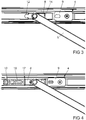
Figur 2 nach einer Anpassung, - Fig.4
- die Vorrichtung aus
Figur 2 nach einer weiteren Anpassung mit einem Reibungselement, - Fig.5
- Bauteile der Vorrichtung aus
Figur 4 in einer perspektivischen Darstellung, - Fig.6
- die Bauteile aus
Figur 5 nach einer Bewegung, - Fig.7
- einen Längsschnitt durch ein flügelseitiges Beschlagteil aus
Figur 2 , - Fig.8
- einen Längsschnitt durch eine alternative Halterung eines Stoppers.
-
Figur 1 zeigt einen Eckbereich eines Fensters mit einem gegen einen Rahmen 1 schwenkbaren Flügel 2. Der Flügel 2 ist an nicht dargestellten Lagern um eine vertikale Achse 3 drehbar. Alternativ dazu kann der Flügel auch um eine nicht dargestellte horizontale Achse kippbar gelagert sein. Die Öffnungsweite des Flügels 2 ist von einer Vorrichtung 4 mit einem am Rahmen 1 und am Flügel 2 gelagerten Ausstellarm 5 begrenzt. Zur Lagerung hat der Ausstellarm 5 am Rahmen 1 und am Flügel 2 angeordnete Beschlagteile 6, 7. Das am Flügel 2 angeordnete Beschlagteil 7 hat einen Gleiter 8 und einen Stopper 9. Der Gleiter 8 ist in einer Beschlagnut 10 längsverschieblich geführt und hat eine Lagerachse 11 für ein Ende des Ausstellarms 5. Der Stopper 9 ist in der Beschlagnut 10 befestigt und begrenzt damit durch seine Position die Öffnungsweite des Flügels 2. -
Figur 2 zeigt in einer Draufsicht der Vorrichtung 4 vergrößert das flügelseitige Beschlagteil 7 ausFigur 1 mit einem Teilbereich des Ausstellarms 5. Der Gleiter 8 und der Stopper 9 weisen jeweils ein Rastmittel 12, 13 auf. Ein erstes Rastmittel 12 des Gleiters 8 ist teilkreisförmig gestaltet, während ein zweites Rastmittel 13 des Stoppers 9 C-förmig, das teilkreisförmige Rastmittel 12 teilweise umgreifend gestaltet ist. In der dargestellten Position sind die Rastmittel 12, 13 ineinander verrastet und damit der Flügel 2 kraftschlüssig gehalten. Beim Schließen des Flügels 2 werden die Rastmittel 12, 13 gelöst und der Gleiter 8 kann sich von dem Stopper 9 entfernen. An seinem dem Rastmittel 12 abgewandten Ende hat der Gleiter 8 eine vertikal zu seiner Verschieberichtung ausgerichtete Prallfläche 14. Die Beschlagnut 10 ist im Querschnitt C-förmig gestaltet und hat Längsstege 15, welche von Bauteilen des Gleiters 8 und des Stoppers 9 hintergriffen werden. Die Hintergreifung der Längsstege ist inFigur 7 dargestellt und wird weiter unten näher erläutert. -
Figur 3 zeigt die Draufsicht der Vorrichtung 4 ausFigur 2 nach einer umgedrehten Montage des Gleiters 8. Der Gleiter 8 ist hier mit der Prallfläche 14 dem Stopper 9 zugewandt montiert. Das inFigur 2 dargestellte Rastmittel 13 des Stoppers 9 wurde zudem entfernt. Damit gelangt der Gleiter 8 bei Erreichen der Öffnungsweite mit seiner Prallfläche 14 gegen den Stopper 9. Eine Verrastung findet damit nicht statt. -
Figur 4 zeigt die Draufsicht der Vorrichtung 4 ausFigur 2 nach einer Montage eines Reibungskörpers 16. Der Reibungskörper 16 und der Gleiter 8 weisen miteinander korrespondierende Koppelmittel 17 zu ihrer formschlüssigen Verbindung auf. Der Reibungskörper 16 erzeugt bei der Bewegung mit dem Gleiter 8 eine vorgesehene Reibung in der Beschlagnut 10, so dass die Bewegung des Flügels 2 gedämpft wird. -
Figur 5 zeigt die Bauteile der Vorrichtung 4 ausFigur 4 in einer perspektivischen Darstellung von der Beschlagnut 10 aus. Hierbei ist zu erkennen, dass der Stopper 9 einen brückenförmigen Grundkörper aufweist, mit dem er das zweite Rastmittel 13 formschlüssig übergreift. Wenn das zweite Rastmittel 13 wie bei der inFigur 3 dargestellten Ausführung nicht gebraucht wird, lässt es sich einfach entfernen und der Stopper 9 ohne Rastmittel 13 montieren. Der Stopper 9 hat einen in die Beschlagnut 10 eindringenden und verdrehbaren Haltekörper 18. Der Haltekörper 18 lässt sich in einer Drehstellung zwischen den Längsstegen 15 der Beschlagnut 10 einsetzen und hintergreift in einer verdrehten Stellung die inFigur 2 dargestellten Längsstege 15 der Beschlagnut 10. Hierbei wird zudem der Stopper 9 in der Beschlagnut 10 festgespannt. Der Gleiter 8 hat ebenfalls einen an einem brückenförmigen Grundkörper verdrehbaren Gleitkörper 19 zur Hintergreifung der Längsstege 15 der Beschlagnut 10. Die Koppelmittel 17 ermöglichen ein Ineinanderstecken der Enden des Gleiters 8 und des Reibungskörpers 16. -
Figur 6 zeigt zur Verdeutlichung die Vorrichtung ausFigur 5 beim Schließen des Flügels 2. Hierbei ist zu erkennen, dass die Rastmittel 12, 13 des Gleiters 8 und des Stoppers 9 voneinander getrennt sind. -
Figur 7 zeigt einen Längsschnitt durch die Vorrichtung 4 ausFigur 2 entlang der Linie VII - VII. Das Haltemittel 18 des Stoppers 9 hintergreift die Längsstege 15 der Beschlagnut 10. Die Enden des bügelförmigen Stoppers 9 stützen sich am Boden der Beschlagnut 10 ab. Zur Verkrallung in der Beschlagnut 10 haben die Enden des Stoppers mehrere Spitzen 20. Der Gleitkörper 19 des Gleiters 8 hat Spiel unterhalb der Längsstege 15. -
Figur 8 zeigt eine weitere Ausführungsform des Stoppers 109. Der Stopper 109 hat eine im Wesentlichen U-förmige Federklammer 21. Die Federklammer 21 ist von einem Haltekörper 118 mit den Enden gegen den Boden der Beschlagnut 10 vorgespannt.
Claims (10)
- Vorrichtung (4) zur Begrenzung einer Öffnungsweite eines gegenüber einem Rahmen (1) um zumindest eine Achse (3) schwenkbaren Flügels (2) eines Fensters, einer Fenstertür oder dergleichen mit einem an einem flügelfesten Beschlagteil (7) und einem rahmenfesten Beschlagteil (6) gelagerten Ausstellarm (5), wobei eines der Beschlagteile (7) einen zur Führung in einer Beschlagnut (10) des Flügels (2) oder des Rahmens (1) gestalteten Gleiter (8) und einen zur feststehenden Montage in der Beschlagnut (10) ausgebildeten Stopper (9) hat, und dass ein Ende des Gleiters (8) ein erstes Rastmittel (12) und der Stopper (9) ein zweites, mit dem ersten Rastmittel (121) korrespondierende Rastmittel (13) aufweist, dadurch gekennzeichnet, dass der Gleiter (8) eine Prallfläche (14) hat, dass die Prallfläche (14) zur Abstützung am Stopper (9) vertikal zur Verschieberichtung des Gleiters (8) ausgerichtet ist und dass der Gleiter (8) zur wahlweisen Montage mit der Prallfläche (14) oder dem ersten Rastmittel (12) gegenüber dem Stopper ausgebildet ist.
- Vorrichtung nach Anspruch 1, dadurch gekennzeichnet, dass die Prall-fläche (14) und das erste Rastmittel (12) an einander gegenüberliegenden Enden des Gleiters (8) angeordnet sind.
- Vorrichtung nach Anspruch 1 oder 2, dadurch gekennzeichnet, dass der Stopper (9) Haltemittel zur Verklemmung oder Verkrallung des Stoppers (9) in der Beschlagnut (10) hat.
- Vorrichtung nach zumindest einem der vorhergehenden Ansprüche, dadurch gekennzeichnet, dass zumindest eines der Rastmittel (12, 13) formschlüssig mit einem Grundkörper des Stoppers (9) oder des Gleiters (8) verbunden ist.
- Vorrichtung nach zumindest einem der vorhergehenden Ansprüche, dadurch gekennzeichnet, dass eines der Rastmittel (12) teilkreisförmig und das andere Rastmittel (13) C-förmig gestaltet ist, wobei im verrasteten Zu-stand der Rastmittel das C-förmig gestaltete Rastmittel (13) das teilkreisförmige Rastmittel (12) um mehr als 180° umgreift.
- Vorrichtung nach zumindest einem der vorhergehenden Ansprüche, dadurch gekennzeichnet, dass der Grundkörper des Stoppers (9) brücken-förmig gestaltet ist und das zweite Rastmittel (13) übergreift.
- Vorrichtung nach zumindest einem der vorhergehenden Ansprüche, dadurch gekennzeichnet, dass der Stopper (9) einen zum Eingreifen in die Beschlagnut (10) vorgesehenen, zwischen einer in der Beschlagnut (10) gehaltenen Haltestellung und einer gegenüber der Beschlagnut (10) lösbaren Montagestellung bewegbaren Haltekörper (18, 118) hat.
- Vorrichtung nach Anspruch 7, dadurch gekennzeichnet, dass der Halte-körper (18, 118) eine Schmalseite hat, mit der er zwischen Längsstegen (15) einer C-förmig gestalteten Beschlagnut (10) einführbar ist, und eine Breitseite hat, mit der er die Längsstege (15) der Beschlagnut (10) hintergreift.
- Vorrichtung nach zumindest einem der vorhergehenden Ansprüche, dadurch gekennzeichnet, dass der Stopper (9) eine im Wesentlichen U-förmige Federklammer (21) und Vorspannmittel zur Vorspannung der Enden der Federklammer (21) in die Beschlagnut (10) hat.
- Vorrichtung nach zumindest einem der vorhergehenden Ansprüche, dadurch gekennzeichnet, dass der Gleiter (8) an einem Ende Koppelmittel (17) zur Verbindung mit einem Reibungskörper (16) hat.
Applications Claiming Priority (1)
| Application Number | Priority Date | Filing Date | Title |
|---|---|---|---|
| DE102020201680.1A DE102020201680A1 (de) | 2020-02-11 | 2020-02-11 | Vorrichtung zur Begrenzung einer Öffnungsweite eines gegenüber einem Rahmen um zumindest eine Achse schwenkbaren Flügels |
Publications (2)
| Publication Number | Publication Date |
|---|---|
| EP3865649A1 true EP3865649A1 (de) | 2021-08-18 |
| EP3865649B1 EP3865649B1 (de) | 2024-09-04 |
Family
ID=74130109
Family Applications (1)
| Application Number | Title | Priority Date | Filing Date |
|---|---|---|---|
| EP21150925.2A Active EP3865649B1 (de) | 2020-02-11 | 2021-01-11 | Vorrichtung zur begrenzung einer öffnungsweite eines gegenüber einem rahmen um zumindest eine achse schwenkbaren flügels |
Country Status (4)
| Country | Link |
|---|---|
| EP (1) | EP3865649B1 (de) |
| DE (1) | DE102020201680A1 (de) |
| ES (1) | ES2994120T3 (de) |
| PL (1) | PL3865649T3 (de) |
Cited By (1)
| Publication number | Priority date | Publication date | Assignee | Title |
|---|---|---|---|---|
| DE202024101120U1 (de) | 2024-03-07 | 2024-04-03 | Siegenia-Aubi Kg | Öffnungsbegrenzer |
Citations (5)
| Publication number | Priority date | Publication date | Assignee | Title |
|---|---|---|---|---|
| EP0648909A2 (de) * | 1993-10-15 | 1995-04-19 | Von Duprin, Inc. | Obenliegender Türhalter |
| EP1288413A2 (de) | 2001-08-30 | 2003-03-05 | Roto Frank Ag | Vorrichtung zur Begrenzung der Öffnungsweite eines dreh- und/oder kippbaren Flügels eines Fensters oder einer Tür |
| DE102012104851A1 (de) * | 2012-06-05 | 2013-12-05 | Dorma Gmbh + Co. Kg | Führungsschienenanordnung |
| DE102012104861A1 (de) * | 2012-06-05 | 2013-12-05 | Dorma Gmbh + Co. Kg | Führungsschienenanordnung |
| EP3351713A1 (de) | 2015-09-16 | 2018-07-25 | Sistemas Técnicos Del Accesorio Y Componentes, S.L | Türbegrenzer |
-
2020
- 2020-02-11 DE DE102020201680.1A patent/DE102020201680A1/de active Pending
-
2021
- 2021-01-11 ES ES21150925T patent/ES2994120T3/es active Active
- 2021-01-11 PL PL21150925.2T patent/PL3865649T3/pl unknown
- 2021-01-11 EP EP21150925.2A patent/EP3865649B1/de active Active
Patent Citations (5)
| Publication number | Priority date | Publication date | Assignee | Title |
|---|---|---|---|---|
| EP0648909A2 (de) * | 1993-10-15 | 1995-04-19 | Von Duprin, Inc. | Obenliegender Türhalter |
| EP1288413A2 (de) | 2001-08-30 | 2003-03-05 | Roto Frank Ag | Vorrichtung zur Begrenzung der Öffnungsweite eines dreh- und/oder kippbaren Flügels eines Fensters oder einer Tür |
| DE102012104851A1 (de) * | 2012-06-05 | 2013-12-05 | Dorma Gmbh + Co. Kg | Führungsschienenanordnung |
| DE102012104861A1 (de) * | 2012-06-05 | 2013-12-05 | Dorma Gmbh + Co. Kg | Führungsschienenanordnung |
| EP3351713A1 (de) | 2015-09-16 | 2018-07-25 | Sistemas Técnicos Del Accesorio Y Componentes, S.L | Türbegrenzer |
Cited By (2)
| Publication number | Priority date | Publication date | Assignee | Title |
|---|---|---|---|---|
| DE202024101120U1 (de) | 2024-03-07 | 2024-04-03 | Siegenia-Aubi Kg | Öffnungsbegrenzer |
| WO2025185870A1 (de) | 2024-03-07 | 2025-09-12 | Siegenia-Aubi Kg | Öffnungsbegrenzer |
Also Published As
| Publication number | Publication date |
|---|---|
| DE102020201680A1 (de) | 2021-08-12 |
| ES2994120T3 (en) | 2025-01-17 |
| PL3865649T3 (pl) | 2024-11-18 |
| EP3865649B1 (de) | 2024-09-04 |
Similar Documents
| Publication | Publication Date | Title |
|---|---|---|
| EP2811092A2 (de) | Tür oder Fenster mit einem Schwenkbeschlag | |
| EP2085553B1 (de) | Eckband eines Ecklagers | |
| DE3026082C2 (de) | Trittstufe für Kraftfahrzeuge | |
| WO2021115656A1 (de) | Schiebe- und drehflügelsystem | |
| EP3621484B1 (de) | Haltevorrichtung für eine frontblende einer schublade | |
| DE2702470B2 (de) | Feststellvorichtung für eine Tür, insbesondere an Kraftfahrzeugen | |
| DE202005015034U1 (de) | Gleitstück für einen Beschlag | |
| EP3865649B1 (de) | Vorrichtung zur begrenzung einer öffnungsweite eines gegenüber einem rahmen um zumindest eine achse schwenkbaren flügels | |
| AT524607B1 (de) | Anordnung zur Führung eines bewegbaren Möbelteils | |
| DE102007024572B4 (de) | Scharnier für eine Kraftfahrzeugtür | |
| DE2658626C3 (de) | Schaltsperre für Treibstangenbeschläge | |
| EP4074931B1 (de) | Beschlag mit einem durch längsschieben arretierbaren rasthaken | |
| EP3688260B1 (de) | In der kippstellung verrastbarer und dennoch beim schieb-schliessen leicht bewegbarer beschlag für ein fenster oder eine tür | |
| EP0292683B1 (de) | Kraftwagen-Türfeststeller | |
| EP3771793B1 (de) | Beschlag für eine schiebetür | |
| DE112008000005T5 (de) | Dreifachklemmen-Verriegelungsvorrichtung | |
| DE3004830C2 (de) | Aufreihvorrichtung für einen Ringordner | |
| DE102007021979B3 (de) | Gleitvorrichtung für Schiebe- oder Abstellschiebeflügel | |
| DE3517067C2 (de) | ||
| EP2479363B1 (de) | Verschluss für einen Treibstangenbeschlag | |
| EP3296492A1 (de) | Führungssystem für eine schiebetür sowie schiebetür mit einem führungssystem und entsprechend ausgestattetes kraftfahrzeug | |
| DE3718840C1 (en) | Window lifter for motor vehicles | |
| DE102012222210A1 (de) | Zur verdeckten Anordnung vorgesehenes Ecklager | |
| EP4124709B1 (de) | Führungsprofil für eine auszugssperre, auszugssperre, möbel und verfahren zur bestückung eines führungsprofils | |
| DE102013219734B3 (de) | Verriegelungseinheit für einen fahrzeugsitz und fahrzeugsitz |
Legal Events
| Date | Code | Title | Description |
|---|---|---|---|
| PUAI | Public reference made under article 153(3) epc to a published international application that has entered the european phase |
Free format text: ORIGINAL CODE: 0009012 |
|
| STAA | Information on the status of an ep patent application or granted ep patent |
Free format text: STATUS: THE APPLICATION HAS BEEN PUBLISHED |
|
| AK | Designated contracting states |
Kind code of ref document: A1 Designated state(s): AL AT BE BG CH CY CZ DE DK EE ES FI FR GB GR HR HU IE IS IT LI LT LU LV MC MK MT NL NO PL PT RO RS SE SI SK SM TR |
|
| STAA | Information on the status of an ep patent application or granted ep patent |
Free format text: STATUS: REQUEST FOR EXAMINATION WAS MADE |
|
| 17P | Request for examination filed |
Effective date: 20220119 |
|
| RBV | Designated contracting states (corrected) |
Designated state(s): AL AT BE BG CH CY CZ DE DK EE ES FI FR GB GR HR HU IE IS IT LI LT LU LV MC MK MT NL NO PL PT RO RS SE SI SK SM TR |
|
| P01 | Opt-out of the competence of the unified patent court (upc) registered |
Effective date: 20230516 |
|
| GRAP | Despatch of communication of intention to grant a patent |
Free format text: ORIGINAL CODE: EPIDOSNIGR1 |
|
| STAA | Information on the status of an ep patent application or granted ep patent |
Free format text: STATUS: GRANT OF PATENT IS INTENDED |
|
| INTG | Intention to grant announced |
Effective date: 20240429 |
|
| GRAS | Grant fee paid |
Free format text: ORIGINAL CODE: EPIDOSNIGR3 |
|
| GRAA | (expected) grant |
Free format text: ORIGINAL CODE: 0009210 |
|
| STAA | Information on the status of an ep patent application or granted ep patent |
Free format text: STATUS: THE PATENT HAS BEEN GRANTED |
|
| AK | Designated contracting states |
Kind code of ref document: B1 Designated state(s): AL AT BE BG CH CY CZ DE DK EE ES FI FR GB GR HR HU IE IS IT LI LT LU LV MC MK MT NL NO PL PT RO RS SE SI SK SM TR |
|
| REG | Reference to a national code |
Ref country code: GB Ref legal event code: FG4D Free format text: NOT ENGLISH |
|
| REG | Reference to a national code |
Ref country code: CH Ref legal event code: EP |
|
| REG | Reference to a national code |
Ref country code: IE Ref legal event code: FG4D Free format text: LANGUAGE OF EP DOCUMENT: GERMAN |
|
| REG | Reference to a national code |
Ref country code: DE Ref legal event code: R096 Ref document number: 502021005005 Country of ref document: DE |
|
| REG | Reference to a national code |
Ref country code: DE Ref legal event code: R081 Ref document number: 502021005005 Country of ref document: DE Owner name: AUG. WINKHAUS SE & CO. KG, DE Free format text: FORMER OWNER: AUG. WINKHAUS GMBH & CO. KG, 48291 TELGTE, DE Ref country code: DE Ref legal event code: R081 Ref document number: 502021005005 Country of ref document: DE Owner name: AUG. WINKHAUS SE, DE Free format text: FORMER OWNER: AUG. WINKHAUS GMBH & CO. KG, 48291 TELGTE, DE |
|
| RAP4 | Party data changed (patent owner data changed or rights of a patent transferred) |
Owner name: AUG. WINKHAUS SE & CO. KG |
|
| REG | Reference to a national code |
Ref country code: LT Ref legal event code: MG9D |
|
| REG | Reference to a national code |
Ref country code: NL Ref legal event code: MP Effective date: 20240904 |
|
| PG25 | Lapsed in a contracting state [announced via postgrant information from national office to epo] |
Ref country code: NO Free format text: LAPSE BECAUSE OF FAILURE TO SUBMIT A TRANSLATION OF THE DESCRIPTION OR TO PAY THE FEE WITHIN THE PRESCRIBED TIME-LIMIT Effective date: 20241204 |
|
| PG25 | Lapsed in a contracting state [announced via postgrant information from national office to epo] |
Ref country code: GR Free format text: LAPSE BECAUSE OF FAILURE TO SUBMIT A TRANSLATION OF THE DESCRIPTION OR TO PAY THE FEE WITHIN THE PRESCRIBED TIME-LIMIT Effective date: 20241205 Ref country code: FI Free format text: LAPSE BECAUSE OF FAILURE TO SUBMIT A TRANSLATION OF THE DESCRIPTION OR TO PAY THE FEE WITHIN THE PRESCRIBED TIME-LIMIT Effective date: 20240904 |
|
| REG | Reference to a national code |
Ref country code: ES Ref legal event code: FG2A Ref document number: 2994120 Country of ref document: ES Kind code of ref document: T3 Effective date: 20250117 |
|
| PG25 | Lapsed in a contracting state [announced via postgrant information from national office to epo] |
Ref country code: BG Free format text: LAPSE BECAUSE OF FAILURE TO SUBMIT A TRANSLATION OF THE DESCRIPTION OR TO PAY THE FEE WITHIN THE PRESCRIBED TIME-LIMIT Effective date: 20240904 |
|
| PG25 | Lapsed in a contracting state [announced via postgrant information from national office to epo] |
Ref country code: LV Free format text: LAPSE BECAUSE OF FAILURE TO SUBMIT A TRANSLATION OF THE DESCRIPTION OR TO PAY THE FEE WITHIN THE PRESCRIBED TIME-LIMIT Effective date: 20240904 |
|
| PG25 | Lapsed in a contracting state [announced via postgrant information from national office to epo] |
Ref country code: HR Free format text: LAPSE BECAUSE OF FAILURE TO SUBMIT A TRANSLATION OF THE DESCRIPTION OR TO PAY THE FEE WITHIN THE PRESCRIBED TIME-LIMIT Effective date: 20240904 |
|
| PG25 | Lapsed in a contracting state [announced via postgrant information from national office to epo] |
Ref country code: RS Free format text: LAPSE BECAUSE OF FAILURE TO SUBMIT A TRANSLATION OF THE DESCRIPTION OR TO PAY THE FEE WITHIN THE PRESCRIBED TIME-LIMIT Effective date: 20241204 |
|
| PG25 | Lapsed in a contracting state [announced via postgrant information from national office to epo] |
Ref country code: RS Free format text: LAPSE BECAUSE OF FAILURE TO SUBMIT A TRANSLATION OF THE DESCRIPTION OR TO PAY THE FEE WITHIN THE PRESCRIBED TIME-LIMIT Effective date: 20241204 Ref country code: NO Free format text: LAPSE BECAUSE OF FAILURE TO SUBMIT A TRANSLATION OF THE DESCRIPTION OR TO PAY THE FEE WITHIN THE PRESCRIBED TIME-LIMIT Effective date: 20241204 Ref country code: LV Free format text: LAPSE BECAUSE OF FAILURE TO SUBMIT A TRANSLATION OF THE DESCRIPTION OR TO PAY THE FEE WITHIN THE PRESCRIBED TIME-LIMIT Effective date: 20240904 Ref country code: HR Free format text: LAPSE BECAUSE OF FAILURE TO SUBMIT A TRANSLATION OF THE DESCRIPTION OR TO PAY THE FEE WITHIN THE PRESCRIBED TIME-LIMIT Effective date: 20240904 Ref country code: GR Free format text: LAPSE BECAUSE OF FAILURE TO SUBMIT A TRANSLATION OF THE DESCRIPTION OR TO PAY THE FEE WITHIN THE PRESCRIBED TIME-LIMIT Effective date: 20241205 Ref country code: FI Free format text: LAPSE BECAUSE OF FAILURE TO SUBMIT A TRANSLATION OF THE DESCRIPTION OR TO PAY THE FEE WITHIN THE PRESCRIBED TIME-LIMIT Effective date: 20240904 Ref country code: BG Free format text: LAPSE BECAUSE OF FAILURE TO SUBMIT A TRANSLATION OF THE DESCRIPTION OR TO PAY THE FEE WITHIN THE PRESCRIBED TIME-LIMIT Effective date: 20240904 |
|
| PG25 | Lapsed in a contracting state [announced via postgrant information from national office to epo] |
Ref country code: NL Free format text: LAPSE BECAUSE OF FAILURE TO SUBMIT A TRANSLATION OF THE DESCRIPTION OR TO PAY THE FEE WITHIN THE PRESCRIBED TIME-LIMIT Effective date: 20240904 |
|
| PG25 | Lapsed in a contracting state [announced via postgrant information from national office to epo] |
Ref country code: IS Free format text: LAPSE BECAUSE OF FAILURE TO SUBMIT A TRANSLATION OF THE DESCRIPTION OR TO PAY THE FEE WITHIN THE PRESCRIBED TIME-LIMIT Effective date: 20250104 Ref country code: PT Free format text: LAPSE BECAUSE OF FAILURE TO SUBMIT A TRANSLATION OF THE DESCRIPTION OR TO PAY THE FEE WITHIN THE PRESCRIBED TIME-LIMIT Effective date: 20250106 |
|
| PG25 | Lapsed in a contracting state [announced via postgrant information from national office to epo] |
Ref country code: RO Free format text: LAPSE BECAUSE OF FAILURE TO SUBMIT A TRANSLATION OF THE DESCRIPTION OR TO PAY THE FEE WITHIN THE PRESCRIBED TIME-LIMIT Effective date: 20240904 Ref country code: SM Free format text: LAPSE BECAUSE OF FAILURE TO SUBMIT A TRANSLATION OF THE DESCRIPTION OR TO PAY THE FEE WITHIN THE PRESCRIBED TIME-LIMIT Effective date: 20240904 |
|
| PG25 | Lapsed in a contracting state [announced via postgrant information from national office to epo] |
Ref country code: EE Free format text: LAPSE BECAUSE OF FAILURE TO SUBMIT A TRANSLATION OF THE DESCRIPTION OR TO PAY THE FEE WITHIN THE PRESCRIBED TIME-LIMIT Effective date: 20240904 |
|
| PG25 | Lapsed in a contracting state [announced via postgrant information from national office to epo] |
Ref country code: CZ Free format text: LAPSE BECAUSE OF FAILURE TO SUBMIT A TRANSLATION OF THE DESCRIPTION OR TO PAY THE FEE WITHIN THE PRESCRIBED TIME-LIMIT Effective date: 20240904 |
|
| PG25 | Lapsed in a contracting state [announced via postgrant information from national office to epo] |
Ref country code: SK Free format text: LAPSE BECAUSE OF FAILURE TO SUBMIT A TRANSLATION OF THE DESCRIPTION OR TO PAY THE FEE WITHIN THE PRESCRIBED TIME-LIMIT Effective date: 20240904 |
|
| REG | Reference to a national code |
Ref country code: DE Ref legal event code: R097 Ref document number: 502021005005 Country of ref document: DE |
|
| PG25 | Lapsed in a contracting state [announced via postgrant information from national office to epo] |
Ref country code: DK Free format text: LAPSE BECAUSE OF FAILURE TO SUBMIT A TRANSLATION OF THE DESCRIPTION OR TO PAY THE FEE WITHIN THE PRESCRIBED TIME-LIMIT Effective date: 20240904 |
|
| PLBE | No opposition filed within time limit |
Free format text: ORIGINAL CODE: 0009261 |
|
| STAA | Information on the status of an ep patent application or granted ep patent |
Free format text: STATUS: NO OPPOSITION FILED WITHIN TIME LIMIT |
|
| 26N | No opposition filed |
Effective date: 20250605 |
|
| REG | Reference to a national code |
Ref country code: CH Ref legal event code: PL |
|
| REG | Reference to a national code |
Ref country code: DE Ref legal event code: R081 Ref document number: 502021005005 Country of ref document: DE Owner name: AUG. WINKHAUS SE, DE Free format text: FORMER OWNER: AUG. WINKHAUS SE & CO. KG, 48291 TELGTE, DE |
|
| PG25 | Lapsed in a contracting state [announced via postgrant information from national office to epo] |
Ref country code: SE Free format text: LAPSE BECAUSE OF FAILURE TO SUBMIT A TRANSLATION OF THE DESCRIPTION OR TO PAY THE FEE WITHIN THE PRESCRIBED TIME-LIMIT Effective date: 20240904 |
|
| PG25 | Lapsed in a contracting state [announced via postgrant information from national office to epo] |
Ref country code: LU Free format text: LAPSE BECAUSE OF NON-PAYMENT OF DUE FEES Effective date: 20250111 Ref country code: MC Free format text: LAPSE BECAUSE OF FAILURE TO SUBMIT A TRANSLATION OF THE DESCRIPTION OR TO PAY THE FEE WITHIN THE PRESCRIBED TIME-LIMIT Effective date: 20240904 |
|
| GBPC | Gb: european patent ceased through non-payment of renewal fee |
Effective date: 20250111 |
|
| PG25 | Lapsed in a contracting state [announced via postgrant information from national office to epo] |
Ref country code: GB Free format text: LAPSE BECAUSE OF NON-PAYMENT OF DUE FEES Effective date: 20250111 |
|
| PG25 | Lapsed in a contracting state [announced via postgrant information from national office to epo] |
Ref country code: FR Free format text: LAPSE BECAUSE OF NON-PAYMENT OF DUE FEES Effective date: 20250131 |
|
| PG25 | Lapsed in a contracting state [announced via postgrant information from national office to epo] |
Ref country code: CH Free format text: LAPSE BECAUSE OF NON-PAYMENT OF DUE FEES Effective date: 20250131 |
|
| PG25 | Lapsed in a contracting state [announced via postgrant information from national office to epo] |
Ref country code: IE Free format text: LAPSE BECAUSE OF NON-PAYMENT OF DUE FEES Effective date: 20250111 |
|
| PGFP | Annual fee paid to national office [announced via postgrant information from national office to epo] |
Ref country code: ES Payment date: 20260217 Year of fee payment: 6 |
|
| PGFP | Annual fee paid to national office [announced via postgrant information from national office to epo] |
Ref country code: DE Payment date: 20260120 Year of fee payment: 6 |
|
| PGFP | Annual fee paid to national office [announced via postgrant information from national office to epo] |
Ref country code: AT Payment date: 20260119 Year of fee payment: 6 |
|
| PGFP | Annual fee paid to national office [announced via postgrant information from national office to epo] |
Ref country code: BE Payment date: 20260121 Year of fee payment: 6 Ref country code: IT Payment date: 20260130 Year of fee payment: 6 |
|
| PGFP | Annual fee paid to national office [announced via postgrant information from national office to epo] |
Ref country code: PL Payment date: 20260109 Year of fee payment: 6 |