EP0648909A2 - Obenliegender Türhalter - Google Patents
Obenliegender Türhalter Download PDFInfo
- Publication number
- EP0648909A2 EP0648909A2 EP94307548A EP94307548A EP0648909A2 EP 0648909 A2 EP0648909 A2 EP 0648909A2 EP 94307548 A EP94307548 A EP 94307548A EP 94307548 A EP94307548 A EP 94307548A EP 0648909 A2 EP0648909 A2 EP 0648909A2
- Authority
- EP
- European Patent Office
- Prior art keywords
- assembly
- door
- channel
- slide
- jamb
- Prior art date
- Legal status (The legal status is an assumption and is not a legal conclusion. Google has not performed a legal analysis and makes no representation as to the accuracy of the status listed.)
- Withdrawn
Links
- 230000000712 assembly Effects 0.000 claims abstract description 8
- 238000000429 assembly Methods 0.000 claims abstract description 8
- 230000006835 compression Effects 0.000 claims description 6
- 238000007906 compression Methods 0.000 claims description 6
- 239000004677 Nylon Substances 0.000 claims description 4
- 229920001778 nylon Polymers 0.000 claims description 4
- 229920001169 thermoplastic Polymers 0.000 claims description 4
- 239000004416 thermosoftening plastic Substances 0.000 claims description 4
- 230000004044 response Effects 0.000 claims description 2
- 230000002441 reversible effect Effects 0.000 claims 1
- 230000007246 mechanism Effects 0.000 description 4
- 229920006074 Nylatron® Polymers 0.000 description 2
- 229910000831 Steel Inorganic materials 0.000 description 2
- 238000005461 lubrication Methods 0.000 description 2
- 239000000463 material Substances 0.000 description 2
- 230000004048 modification Effects 0.000 description 2
- 238000012986 modification Methods 0.000 description 2
- 239000010959 steel Substances 0.000 description 2
- 229910001369 Brass Inorganic materials 0.000 description 1
- OKTJSMMVPCPJKN-UHFFFAOYSA-N Carbon Chemical compound [C] OKTJSMMVPCPJKN-UHFFFAOYSA-N 0.000 description 1
- 206010017577 Gait disturbance Diseases 0.000 description 1
- 239000010951 brass Substances 0.000 description 1
- 230000008859 change Effects 0.000 description 1
- 238000010276 construction Methods 0.000 description 1
- 230000000694 effects Effects 0.000 description 1
- 239000002783 friction material Substances 0.000 description 1
- 229910002804 graphite Inorganic materials 0.000 description 1
- 239000010439 graphite Substances 0.000 description 1
- 239000003779 heat-resistant material Substances 0.000 description 1
- 238000003780 insertion Methods 0.000 description 1
- 230000037431 insertion Effects 0.000 description 1
- 239000000314 lubricant Substances 0.000 description 1
- 239000002184 metal Substances 0.000 description 1
- 238000000034 method Methods 0.000 description 1
- 239000003921 oil Substances 0.000 description 1
- 230000000737 periodic effect Effects 0.000 description 1
- 229920000642 polymer Polymers 0.000 description 1
- 239000007787 solid Substances 0.000 description 1
- 230000003068 static effect Effects 0.000 description 1
Images



Classifications
-
- E—FIXED CONSTRUCTIONS
- E05—LOCKS; KEYS; WINDOW OR DOOR FITTINGS; SAFES
- E05C—BOLTS OR FASTENING DEVICES FOR WINGS, SPECIALLY FOR DOORS OR WINDOWS
- E05C17/00—Devices for holding wings open; Devices for limiting opening of wings or for holding wings open by a movable member extending between frame and wing; Braking devices, stops or buffers, combined therewith
- E05C17/02—Devices for holding wings open; Devices for limiting opening of wings or for holding wings open by a movable member extending between frame and wing; Braking devices, stops or buffers, combined therewith by mechanical means
- E05C17/04—Devices for holding wings open; Devices for limiting opening of wings or for holding wings open by a movable member extending between frame and wing; Braking devices, stops or buffers, combined therewith by mechanical means with a movable bar or equivalent member extending between frame and wing
- E05C17/12—Devices for holding wings open; Devices for limiting opening of wings or for holding wings open by a movable member extending between frame and wing; Braking devices, stops or buffers, combined therewith by mechanical means with a movable bar or equivalent member extending between frame and wing consisting of a single rod
- E05C17/24—Devices for holding wings open; Devices for limiting opening of wings or for holding wings open by a movable member extending between frame and wing; Braking devices, stops or buffers, combined therewith by mechanical means with a movable bar or equivalent member extending between frame and wing consisting of a single rod pivoted at one end, and with the other end running along a guide member
- E05C17/28—Devices for holding wings open; Devices for limiting opening of wings or for holding wings open by a movable member extending between frame and wing; Braking devices, stops or buffers, combined therewith by mechanical means with a movable bar or equivalent member extending between frame and wing consisting of a single rod pivoted at one end, and with the other end running along a guide member with braking, clamping or securing means at the connection to the guide member
-
- E—FIXED CONSTRUCTIONS
- E05—LOCKS; KEYS; WINDOW OR DOOR FITTINGS; SAFES
- E05B—LOCKS; ACCESSORIES THEREFOR; HANDCUFFS
- E05B15/00—Other details of locks; Parts for engagement by bolts of fastening devices
- E05B15/16—Use of special materials for parts of locks
- E05B15/1635—Use of special materials for parts of locks of plastics materials
-
- Y—GENERAL TAGGING OF NEW TECHNOLOGICAL DEVELOPMENTS; GENERAL TAGGING OF CROSS-SECTIONAL TECHNOLOGIES SPANNING OVER SEVERAL SECTIONS OF THE IPC; TECHNICAL SUBJECTS COVERED BY FORMER USPC CROSS-REFERENCE ART COLLECTIONS [XRACs] AND DIGESTS
- Y10—TECHNICAL SUBJECTS COVERED BY FORMER USPC
- Y10T—TECHNICAL SUBJECTS COVERED BY FORMER US CLASSIFICATION
- Y10T292/00—Closure fasteners
- Y10T292/28—Extension link
- Y10T292/304—Sliding catch
Definitions
- This invention relates to an overhead door holder assembly and more particularly to a modular door holder assembly having interchangeable sliding elements with reduced sliding friction.
- Temporarily holding a door in an open position is often necessary for convenience and safety, and one commonly employed method uses an overhead door control device that includes a pivoting arm attached between an upper portion of a door jamb and an upper part of a door.
- an overhead door control device that includes a pivoting arm attached between an upper portion of a door jamb and an upper part of a door.
- a door holder assembly for attachment between a door jamb and a door for selectively holding the door in an open position
- the assembly comprising a jamb bracket for attachment to the door jamb; a jamb arm pivotally attached to the jamb bracket; a channel assembly having a channel therein defined by channel walls; and a slide assembly selectively engageable with the channel assembly to hold open the door in use, and the slide assembly being pivotally attached to the jamb arm for movement in response to opening or closing of the door, characterised in that the slide assembly supports at least one low friction polymeric block in contact with the channel walls.
- a modular overhead door holder system comprising a jamb arm for pivotal attachment to a door jamb; a channel assembly having a channel therein defined by channel walls, and a plurality of slide assemblies, each slide assembly being configured to fit into the channel for sliding movement therein; characterised in that any one of the plurality of slide assemblies is selected for positioning in the channel and for pivotal connection with the jamb arm and there being means for engaging the selected one of the plurality of slide assemblies and the channel assembly to control positioning of a door.
- the invention also extends to a door incorporating a door holder assembly essentially as just defined.
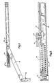
- an overhead door holder assembly 10 has a channel assembly 22 positioned in a door inset 20 at an upper edge 13 of a door 12.
- the channel assembly 22 is attached to the door 12 so that its longitudinally extending and generally U-shaped channel 23 is upwardly open.
- a slide assembly 26 Positioned for sliding movement within the channel 23 is a slide assembly 26.
- the slide assembly 26 has an attached polymeric block 27 for contacting the channel assembly 22 to reduce sliding friction and wear.
- the low friction polymeric block is constructed from durable, inexpensive and low friction materials such as nylon filled thermoplastics.
- nylon filled thermoplastics A favoured nylon filled thermoplastics is the material known and sold under the Registered Trade Mark “Nylatron", produced by Polymer Corporation, of Reading, Pennsylvania, U.S.A.
- Use of the polymeric block 27 extends the useful wear life of the channel assembly 22 and slide assembly 26, eliminates the need for periodic lubrication with oils or solid lubricants such as graphite and reduces noise of door opening or closing.
- the door holder assembly 10 also includes a jamb bracket 16 permanently affixed by screws, bolts, rivets or other fasteners to a door jamb 14.
- a jamb arm 18 is pivotally connected at one end to the jamb bracket 16 and at its opposite end to the slide assembly 26.
- the jamb bracket 16, jamb arm 18 and channel assembly 22 are formed from extruded brass or other durable, wear resistant material such as steel.
- the slide assembly 26 When the door 12 is closed, the slide assembly 26 is positioned in the channel 23 distant from a spring support 24 for a rebound or stop spring 34.
- the pivoting connection of the jamb arm 18 between the jamb bracket 16 and the slide assembly 26 allows the slide assembly 26 to move along the channel 23 toward the spring support 24.
- the slide assembly 26 moves along the channel toward the spring support 24 until the slide assembly contacts and rebounds from the stop spring 34.
- the stop spring 34 absorbs the force of slider movement, preventing damage to the door or door holder assembly 10.
- conventional compression springs are not required to be fitted into the channel assembly.
- polymeric or steel blocks can be fitted in the channel assembly to absorb force of the slider, and other mechanisms for engaging the slider can also be attached to the channel assembly.
- a hold open stop 128, formed from stamped metal and shaped for permanent insertion into the channel assembly 22 has an integrally formed flange 136 that can be snapped into a slot formed in the spring support 24 for locking engagement.
- the hold open stop 128 has a stop element 138.
- the stop element 138 has angled and opposed first and second ramps 139 and 140.
- the first ramp 139 is typically configured to present a wedge shape surface having a dihedral angle of between about 10 degrees to about 40 degrees, with an angle of 25 to 35 degrees being typical.
- the dihedral angle presented by the second ramp 140 is much steeper, having a range of between about 50 degrees to about 85 degrees, with angles of 65 degrees to 75 degrees being typical.
- the stop element 138 engages the slide assembly 126 to hold the door 12 open.
- the slide assembly 26 includes an axle pin 143 for pivotally supporting a rocker 142, and an adjustment wedge 146 to permit altering the force exerted by the rocker 142 on the stop element 138 of the hold open stop 128.
- the adjustment wedge 146 has an internal channel 154 through which passes a position pin 156 connected to the slide assembly 126. The position of the adjustment wedge 146 is itself adjusted by an adjustment screw 148 that engages a compression spring 150 situated between a head of the screw 148 and the adjustment wedge 146.
- Engagement of the slide assembly 126 and the hold open stop 128 requires a catch 144 of the rocker 142 to contact the stop element 138 of the hold open stop 128.
- the catch 144 moves upward on the first ramp 139 of the stop element 138 as the slide assembly moves closer to the hold open stop 28 and ultimately slides down the second ramp 140 of the stop element 138 to a position of locked engagement with the second ramp 140 of the stop element 138, holding the door in an open position.
- a reversal of this sequence is required to disengage the door from the hold open position; however, a greater force is required to pull the catch 144 up the steeper angled second ramp 140 compared to that required to push the catch 144 up the gentler angled first ramp 139. This difference in required force ensures that the door will remain in a held open position as long as required, while permitting a nearly normal opening force to lock the door temporarily in the hold open position.
- Adjustment of the force needed to impel the catch 144 up the first ramp 139 and pull the catch 144 back up the second ramp 140 is modified with the aid of the adjustment wedge 146.
- a rocker face 145 engages a wedge face 152 of the adjustment wedge 146.
- the necessary rotation of the rocker 142 to allow movement of the catch 144 up the first ramp 139 is resisted by the adjustment wedge 146, with the adjustment wedge being pushed against the compression spring 150 and increasing the resistance to rotation of the rocker 142.
- the precise force can be easily adjusted with readily available tools by tightening or loosening the adjustment screw to change the position of the compression spring 150 (and consequently the position of the adjustment wedge 146).
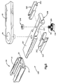
- a slide assembly 226 suitable for modular placement in the channel assembly 22 can incorporate frictional engaging features for holding open a door.
- the slide assembly 226 includes a slider 236 having serrations 237 defined on it, first and second springs 242 and 243, first and second friction pads 244 and 245 (formed from brake lining or other wear and heat resistant material), and a friction cam 238 connected to the slider 236 by its shaft 241 and a nut 240, along with additional locking engagement being provided by matched locking of its serrations 239 and serrations 237 of the slider 236.
- the top surface of the slider 236 has an attached polymeric block 287 constructed from a nylon filled thermoplastics such as "Nylatron" that provides low friction and low wear engagement of the slider 236 with the channel assembly 22 and its channel walls 21.
- the springs 242 and 243 have a generally U-shaped cross sectional shape and are respectively positioned between the centrally located slider 236 and the first and second friction pads 244 and 245. When assembled, the springs 242 and 243 press the pads 244 and 245 against the channel walls 21 of the channel assembly 22, the exact amount of pressure being determined by the angle of rotation of the friction cam 238.
- the friction cam 238 has an elliptical cross section. As the cam 238 is rotated from a first position with the long axis of the ellipse parallel to the channel to an increasingly angled position with respect to the longitudinal axis of the channel assembly, the springs 242 and 243 are increasingly compressed. This compression of the springs 242 and 243 consequently results in greater static and dynamic frictional force exerted by the pads 243 and 244. Depending on the thickness, type of pad, door resistance and other appropriate factors, the friction cam 238 can be adjusted to compress the springs a desired amount by adjusting its rotation angle.
- the friction cam 238 When the friction cam 238 is set at the correct rotational angle, it is slightly rocked so that the serrations 237 of the slider and serrations 239 of the friction cam 238 mesh, providing resistance to movement out of position as the nut 240 is tightened on the shaft 241.
- the present construction allows simple and quick adjustment of door hold force.
- slide mechanism can also be used in conjunction with the present channel assembly.
- the examples described are not intended to limit the particular type of hold open stop, stop block, slide or other modular mechanism suitable for use in conjunction with the channel assembly.
Landscapes
- Engineering & Computer Science (AREA)
- Mechanical Engineering (AREA)
- Closing And Opening Devices For Wings, And Checks For Wings (AREA)
Applications Claiming Priority (2)
| Application Number | Priority Date | Filing Date | Title |
|---|---|---|---|
| US08/138,523 US5426820A (en) | 1993-10-15 | 1993-10-15 | Modular reduced friction overhead door holder assembly |
| US138523 | 2002-05-06 |
Publications (2)
| Publication Number | Publication Date |
|---|---|
| EP0648909A2 true EP0648909A2 (de) | 1995-04-19 |
| EP0648909A3 EP0648909A3 (de) | 1995-06-14 |
Family
ID=22482403
Family Applications (1)
| Application Number | Title | Priority Date | Filing Date |
|---|---|---|---|
| EP94307548A Withdrawn EP0648909A3 (de) | 1993-10-15 | 1994-10-14 | Obenliegender Türhalter. |
Country Status (3)
| Country | Link |
|---|---|
| US (1) | US5426820A (de) |
| EP (1) | EP0648909A3 (de) |
| CA (1) | CA2117978A1 (de) |
Cited By (3)
| Publication number | Priority date | Publication date | Assignee | Title |
|---|---|---|---|---|
| DE202015004372U1 (de) * | 2015-06-18 | 2015-07-20 | Siegenia-Aubi Kg | Endlageeinzugs- und Endlagedämpfungsvorrichtung für einen an einem Rahmen drehbar gelagerten Flügel eines Fensters oder einer Tür |
| CN111706198A (zh) * | 2020-06-05 | 2020-09-25 | 马鞍山市谷庆门业有限公司 | 一种应用于门体的防高速撞击机构 |
| EP3865649A1 (de) * | 2020-02-11 | 2021-08-18 | Aug. Winkhaus GmbH & Co. KG | Vorrichtung zur begrenzung einer öffnungsweite eines gegenüber einem rahmen um zumindest eine achse schwenkbaren flügels |
Families Citing this family (7)
| Publication number | Priority date | Publication date | Assignee | Title |
|---|---|---|---|---|
| US6019892A (en) * | 1997-01-21 | 2000-02-01 | United States Filter Corporation | Guide tracking for cog rake bar screens |
| DE10013163A1 (de) * | 2000-03-17 | 2001-09-20 | Geze Gmbh | Feststellvorrichtung für eine mit einem Türschließer versehene Tür |
| DE10025185C2 (de) * | 2000-05-20 | 2002-12-19 | Edscha Ag | Kugeldruckgleiter-Türfeststeller |
| DE102008061731A1 (de) * | 2008-12-12 | 2010-06-17 | Dorma Gmbh + Co. Kg | Schiebetür |
| DE102008061728A1 (de) * | 2008-12-12 | 2010-06-17 | Dorma Gmbh + Co. Kg | Schiebetür |
| TWM592021U (zh) * | 2019-11-19 | 2020-03-11 | 弘晉五金製品股份有限公司 | 門擋裝置 |
| CN111005632A (zh) * | 2019-12-25 | 2020-04-14 | 安徽正日电气有限公司 | 一种配电柜的开关门结构 |
Family Cites Families (12)
| Publication number | Priority date | Publication date | Assignee | Title |
|---|---|---|---|---|
| GB382734A (en) * | 1931-10-16 | 1932-11-03 | Joseph Steane | Improvements relating to stays for windows, doors and the like |
| US1986677A (en) * | 1932-03-14 | 1935-01-01 | Elvin H Johnson | Builder's hardware |
| US2277316A (en) * | 1941-01-02 | 1942-03-24 | Oscar C Rixson Company | Door holder |
| US3164404A (en) * | 1963-03-08 | 1965-01-05 | Rixson Inc | Automatic hold-open release |
| US3683450A (en) * | 1970-06-22 | 1972-08-15 | Rixson Inc | Friction door holder |
| US3601842A (en) * | 1970-06-22 | 1971-08-31 | Rixson Inc | Door holder |
| US3630560A (en) * | 1970-11-12 | 1971-12-28 | Glynn Johnson Corp | Surface-mounted nonhanded door holder |
| DE7901009U1 (de) * | 1979-01-16 | 1979-04-19 | Wilh. Frank Gmbh, 7022 Leinfelden- Echterdingen | Fluegelfeststeller fuer ein fenster, eine tuer o.dgl. |
| AT378230B (de) * | 1983-12-16 | 1985-07-10 | Mayer & Co Riegel Beschlag | Vorrichtung zum begrenzen der oeffnungsweite des fluegels eines fensters oder einer tuer |
| US4750236A (en) * | 1987-01-02 | 1988-06-14 | Yale Security Inc. | Track-type door hold-open device |
| DE4005203A1 (de) * | 1990-02-20 | 1991-08-22 | Dorma Gmbh & Co Kg | Feststellvorrichtung fuer tuerfluegel mit einem tuerschliesser |
| US5263807A (en) * | 1992-01-08 | 1993-11-23 | Pijanowski Joseph A | Vehicle with multi-positionable flat-bed |
-
1993
- 1993-10-15 US US08/138,523 patent/US5426820A/en not_active Expired - Lifetime
-
1994
- 1994-10-12 CA CA002117978A patent/CA2117978A1/en not_active Abandoned
- 1994-10-14 EP EP94307548A patent/EP0648909A3/de not_active Withdrawn
Cited By (3)
| Publication number | Priority date | Publication date | Assignee | Title |
|---|---|---|---|---|
| DE202015004372U1 (de) * | 2015-06-18 | 2015-07-20 | Siegenia-Aubi Kg | Endlageeinzugs- und Endlagedämpfungsvorrichtung für einen an einem Rahmen drehbar gelagerten Flügel eines Fensters oder einer Tür |
| EP3865649A1 (de) * | 2020-02-11 | 2021-08-18 | Aug. Winkhaus GmbH & Co. KG | Vorrichtung zur begrenzung einer öffnungsweite eines gegenüber einem rahmen um zumindest eine achse schwenkbaren flügels |
| CN111706198A (zh) * | 2020-06-05 | 2020-09-25 | 马鞍山市谷庆门业有限公司 | 一种应用于门体的防高速撞击机构 |
Also Published As
| Publication number | Publication date |
|---|---|
| CA2117978A1 (en) | 1995-04-16 |
| US5426820A (en) | 1995-06-27 |
| EP0648909A3 (de) | 1995-06-14 |
Similar Documents
| Publication | Publication Date | Title |
|---|---|---|
| US7865999B2 (en) | Door motion controller assembly | |
| EP0648909A2 (de) | Obenliegender Türhalter | |
| CN100389703C (zh) | 具有调节机构的抽屉滑动组件 | |
| US6041475A (en) | Locking counterbalance shoe for tiltably removable sash windows | |
| US5901992A (en) | Electromechanical locking mechanism for door leaves having a door closing device | |
| US5450651A (en) | End cap locking overhead mounted door holder assembly | |
| CN1240327C (zh) | 抽屉滑动装置的可调节制动机构 | |
| CA1174080A (en) | Tensioning device | |
| EP0791709A2 (de) | Vorrichtung zum Halten einer Fahrzeugschiebetür in voll geöffneter Stellung | |
| DE19936280B4 (de) | Türscharniersystem | |
| CN101248244B (zh) | 缓冲元件 | |
| EP0649961A1 (de) | Türhalter | |
| US5448798A (en) | Low profile overhead mounted door holder assembly | |
| WO1999020865A1 (en) | Adjustable locking hinge | |
| EP0649963A1 (de) | Türhalter mit wählbarer Reibungsunterstützung | |
| GB2311324A (en) | Releasably lockable window stay | |
| EP0649965A1 (de) | Federbelasteter Verriegelungskolben | |
| CA2231496C (en) | Adjustable shoe for awning window hinge | |
| CA2514299A1 (en) | Track clamping holder for fixing tracks of sliding door systems | |
| WO2004013438A1 (en) | Restricting device | |
| US6032331A (en) | Checking mechanisms with variable plane trigger plates | |
| EP0649960A1 (de) | Türhalter | |
| EP0649964A1 (de) | Einstellvorrichtung für die Haltekraft einer Türfeststellvorrichtung | |
| EP4212689A1 (de) | Hydraulisches scharnier für glastüren | |
| GB2323627A (en) | A locking device for a window stay |
Legal Events
| Date | Code | Title | Description |
|---|---|---|---|
| PUAI | Public reference made under article 153(3) epc to a published international application that has entered the european phase |
Free format text: ORIGINAL CODE: 0009012 |
|
| AK | Designated contracting states |
Kind code of ref document: A2 Designated state(s): DE FR GB IT |
|
| PUAL | Search report despatched |
Free format text: ORIGINAL CODE: 0009013 |
|
| AK | Designated contracting states |
Kind code of ref document: A3 Designated state(s): DE FR GB IT |
|
| 17P | Request for examination filed |
Effective date: 19951211 |
|
| 17Q | First examination report despatched |
Effective date: 19960111 |
|
| STAA | Information on the status of an ep patent application or granted ep patent |
Free format text: STATUS: THE APPLICATION IS DEEMED TO BE WITHDRAWN |
|
| 18D | Application deemed to be withdrawn |
Effective date: 19970301 |