EP3862590B1 - Electric parking brake device - Google Patents
Electric parking brake device Download PDFInfo
- Publication number
- EP3862590B1 EP3862590B1 EP19868445.8A EP19868445A EP3862590B1 EP 3862590 B1 EP3862590 B1 EP 3862590B1 EP 19868445 A EP19868445 A EP 19868445A EP 3862590 B1 EP3862590 B1 EP 3862590B1
- Authority
- EP
- European Patent Office
- Prior art keywords
- engaging member
- insertion hole
- parking brake
- state
- diameter
- Prior art date
- Legal status (The legal status is an assumption and is not a legal conclusion. Google has not performed a legal analysis and makes no representation as to the accuracy of the status listed.)
- Active
Links
Images


Classifications
-
- F—MECHANICAL ENGINEERING; LIGHTING; HEATING; WEAPONS; BLASTING
- F16—ENGINEERING ELEMENTS AND UNITS; GENERAL MEASURES FOR PRODUCING AND MAINTAINING EFFECTIVE FUNCTIONING OF MACHINES OR INSTALLATIONS; THERMAL INSULATION IN GENERAL
- F16D—COUPLINGS FOR TRANSMITTING ROTATION; CLUTCHES; BRAKES
- F16D51/00—Brakes with outwardly-movable braking members co-operating with the inner surface of a drum or the like
- F16D51/16—Brakes with outwardly-movable braking members co-operating with the inner surface of a drum or the like shaped as brake-shoes pivoted on a fixed or nearly-fixed axis
- F16D51/18—Brakes with outwardly-movable braking members co-operating with the inner surface of a drum or the like shaped as brake-shoes pivoted on a fixed or nearly-fixed axis with two brake-shoes
- F16D51/20—Brakes with outwardly-movable braking members co-operating with the inner surface of a drum or the like shaped as brake-shoes pivoted on a fixed or nearly-fixed axis with two brake-shoes extending in opposite directions from their pivots
- F16D51/22—Brakes with outwardly-movable braking members co-operating with the inner surface of a drum or the like shaped as brake-shoes pivoted on a fixed or nearly-fixed axis with two brake-shoes extending in opposite directions from their pivots mechanically actuated
-
- B—PERFORMING OPERATIONS; TRANSPORTING
- B60—VEHICLES IN GENERAL
- B60T—VEHICLE BRAKE CONTROL SYSTEMS OR PARTS THEREOF; BRAKE CONTROL SYSTEMS OR PARTS THEREOF, IN GENERAL; ARRANGEMENT OF BRAKING ELEMENTS ON VEHICLES IN GENERAL; PORTABLE DEVICES FOR PREVENTING UNWANTED MOVEMENT OF VEHICLES; VEHICLE MODIFICATIONS TO FACILITATE COOLING OF BRAKES
- B60T13/00—Transmitting braking action from initiating means to ultimate brake actuator with power assistance or drive; Brake systems incorporating such transmitting means, e.g. air-pressure brake systems
- B60T13/74—Transmitting braking action from initiating means to ultimate brake actuator with power assistance or drive; Brake systems incorporating such transmitting means, e.g. air-pressure brake systems with electrical assistance or drive
- B60T13/741—Transmitting braking action from initiating means to ultimate brake actuator with power assistance or drive; Brake systems incorporating such transmitting means, e.g. air-pressure brake systems with electrical assistance or drive acting on an ultimate actuator
-
- F—MECHANICAL ENGINEERING; LIGHTING; HEATING; WEAPONS; BLASTING
- F16—ENGINEERING ELEMENTS AND UNITS; GENERAL MEASURES FOR PRODUCING AND MAINTAINING EFFECTIVE FUNCTIONING OF MACHINES OR INSTALLATIONS; THERMAL INSULATION IN GENERAL
- F16B—DEVICES FOR FASTENING OR SECURING CONSTRUCTIONAL ELEMENTS OR MACHINE PARTS TOGETHER, e.g. NAILS, BOLTS, CIRCLIPS, CLAMPS, CLIPS OR WEDGES; JOINTS OR JOINTING
- F16B21/00—Means for preventing relative axial movement of a pin, spigot, shaft or the like and a member surrounding it; Stud-and-socket releasable fastenings
- F16B21/10—Means for preventing relative axial movement of a pin, spigot, shaft or the like and a member surrounding it; Stud-and-socket releasable fastenings by separate parts
- F16B21/16—Means for preventing relative axial movement of a pin, spigot, shaft or the like and a member surrounding it; Stud-and-socket releasable fastenings by separate parts with grooves or notches in the pin or shaft
- F16B21/18—Means for preventing relative axial movement of a pin, spigot, shaft or the like and a member surrounding it; Stud-and-socket releasable fastenings by separate parts with grooves or notches in the pin or shaft with circlips or like resilient retaining devices, i.e. resilient in the plane of the ring or the like; Details
- F16B21/183—Means for preventing relative axial movement of a pin, spigot, shaft or the like and a member surrounding it; Stud-and-socket releasable fastenings by separate parts with grooves or notches in the pin or shaft with circlips or like resilient retaining devices, i.e. resilient in the plane of the ring or the like; Details internal, i.e. with spreading action
-
- F—MECHANICAL ENGINEERING; LIGHTING; HEATING; WEAPONS; BLASTING
- F16—ENGINEERING ELEMENTS AND UNITS; GENERAL MEASURES FOR PRODUCING AND MAINTAINING EFFECTIVE FUNCTIONING OF MACHINES OR INSTALLATIONS; THERMAL INSULATION IN GENERAL
- F16D—COUPLINGS FOR TRANSMITTING ROTATION; CLUTCHES; BRAKES
- F16D65/00—Parts or details
- F16D65/14—Actuating mechanisms for brakes; Means for initiating operation at a predetermined position
- F16D65/16—Actuating mechanisms for brakes; Means for initiating operation at a predetermined position arranged in or on the brake
- F16D65/22—Actuating mechanisms for brakes; Means for initiating operation at a predetermined position arranged in or on the brake adapted for pressing members apart, e.g. for drum brakes
-
- F—MECHANICAL ENGINEERING; LIGHTING; HEATING; WEAPONS; BLASTING
- F16—ENGINEERING ELEMENTS AND UNITS; GENERAL MEASURES FOR PRODUCING AND MAINTAINING EFFECTIVE FUNCTIONING OF MACHINES OR INSTALLATIONS; THERMAL INSULATION IN GENERAL
- F16D—COUPLINGS FOR TRANSMITTING ROTATION; CLUTCHES; BRAKES
- F16D2121/00—Type of actuator operation force
- F16D2121/18—Electric or magnetic
- F16D2121/24—Electric or magnetic using motors
-
- F—MECHANICAL ENGINEERING; LIGHTING; HEATING; WEAPONS; BLASTING
- F16—ENGINEERING ELEMENTS AND UNITS; GENERAL MEASURES FOR PRODUCING AND MAINTAINING EFFECTIVE FUNCTIONING OF MACHINES OR INSTALLATIONS; THERMAL INSULATION IN GENERAL
- F16D—COUPLINGS FOR TRANSMITTING ROTATION; CLUTCHES; BRAKES
- F16D2125/00—Components of actuators
- F16D2125/18—Mechanical mechanisms
- F16D2125/20—Mechanical mechanisms converting rotation to linear movement or vice versa
- F16D2125/34—Mechanical mechanisms converting rotation to linear movement or vice versa acting in the direction of the axis of rotation
- F16D2125/40—Screw-and-nut
-
- F—MECHANICAL ENGINEERING; LIGHTING; HEATING; WEAPONS; BLASTING
- F16—ENGINEERING ELEMENTS AND UNITS; GENERAL MEASURES FOR PRODUCING AND MAINTAINING EFFECTIVE FUNCTIONING OF MACHINES OR INSTALLATIONS; THERMAL INSULATION IN GENERAL
- F16D—COUPLINGS FOR TRANSMITTING ROTATION; CLUTCHES; BRAKES
- F16D2125/00—Components of actuators
- F16D2125/18—Mechanical mechanisms
- F16D2125/58—Mechanical mechanisms transmitting linear movement
- F16D2125/60—Cables or chains, e.g. Bowden cables
- F16D2125/62—Fixing arrangements therefor, e.g. cable end attachments
Definitions
- the present invention relates to an electric parking brake device including a parking brake lever capable of generating a parking brake force according to an operation, a brake cable including, at one end thereof, an engagement piece to be engaged with the parking brake lever, and an electric actuator including a drive shaft to be connected, at one end thereof, to the other end of the brake cable and enabling the drive shaft to move reciprocally in an axial direction.
- JP 2008 279827 A discloses an electric parking brake in which operation of a screw shaft of a cable driving device is transmitted to a brake cable.
- WO 2006/050770 A1 and DE 102017214938 A1 also disclose connections between components in electric parking brakes.
- An electric parking brake device configured to gain a parking brake force by pulling a brake cable by an electric actuator and rotationally driving a parking brake lever is known by JP-A-2016-222159 .
- the device disclosed in JP-A-2016-222159 described above is not excellent in terms of assimilability because the brake cable is coupled to a screw shaft member, which is a drive shaft provided in the electric actuator, by caulking coupling, and thus a coupling work between the screw shaft member and the brake cable is cumbersome.
- an object of the present invention to provide an electric parking brake device with improved assemblability by facilitating a coupling work between a drive shaft of an electric actuator and a brake cable.
- the present invention provides an electric parking brake device including: a parking brake lever capable of generating a parking brake force according to an operation; a brake cable including, at one end thereof, an engagement piece to be engaged with the parking brake lever; and an electric actuator including a drive shaft coupled, at one end thereof, to other end of the brake cable and enabling the drive shaft to move reciprocally in an axial direction
- the electric parking brake device has a first characteristic in that an insertion hole is provided on one of a joint and the drive shaft, the joint being secured to the other end of the brake cable, and an insertion shaft part to be inserted into the insertion hole is provided coaxially on the other of the joint and the drive shaft
- the electric parking brake device characterized in that an annular engaging member that can be inserted into the insertion hole together with the insertion shaft part is interposed between an inner periphery of the insertion hole and an outer periphery of the insertion shaft part so as to couple the joint and the drive shaft.
- certain embodiments have a second characteristic in that the insertion hole is formed to have a diameter smaller than an outer diameter of the engaging member when the engaging member repulsively expandable and contractible by an action of an external force is in a natural state, a tapered hole formed to have a diameter increasing as it goes outward in the axial direction and coaxially continuing from one end of the insertion hole is provided on one of the joint and the drive shaft, a first annular recess is formed on the outer periphery of the insertion shaft part, the first annular recess is capable of temporality securing the engaging member in the natural state and allows the engaging member in the temporarily secured state to be contracted in diameter until insertion of the engaging member into the insertion hole is enabled, and a second annular recess configured to rotatably engage an outer peripheral side of the engaging member in an expanded state is formed in the insertion hole.
- certain embodiments have a third characteristic in that the insertion shaft part includes, on the outer periphery thereof, a third annular recess continuing from the first annular recess on a front side of the first annular recess along an insertion direction of the insertion shaft part into the insertion hole and formed to be shallower than the first annular recess while being capable of receiving an inner peripheral side of the engaging member.
- certain embodiments have a fourth characteristic in that the insertion shaft part includes, on the outer periphery thereof, a fourth annular recess including: a small diameter shaft section capable of temporarily securing the engaging member expandable and contractible by an action of an external force in a state of having a maximum outer diameter smaller than an inner diameter of the insertion hole and enabling displacement in a direction orthogonal to a center axis of the insertion shaft part, a first tapered portion having a small diameter end coaxially continuing from a front end of the small diameter shaft section along the insertion direction of the insertion shaft part into the insertion hole, a large diameter shaft section coaxially continuing from a large diameter end of the first tapered portion, and a second tapered portion having a small diameter end coaxially continuing from a front end of the large diameter shaft section along the insertion direction, and the insertion hole includes, on an inner periphery thereof, an annular locking recess, which allows engagement of part of the outer peripher
- certain embodiments have a fifth characteristic in that the insertion shaft part includes, on the outer periphery thereof, a fourth annular recess having a small diameter shaft section capable of temporarily securing the engaging member repulsively expandable and contractible by an action of an external force in a state of having the maximum outer diameter larger than the inner diameter of the insertion hole in the natural state and capable of being contracted in diameter when being inserted into the insertion hole, a first tapered portion having a small diameter end coaxially continuing from a front end of the small diameter shaft section along the insertion direction of the insertion shaft part into the insertion hole, a large diameter shaft section coaxially continuing from a large diameter end of the first tapered portion, and a second tapered portion having a small diameter end coaxially continuing from a front end of the large diameter shaft section along the insertion direction, and the insertion hole includes, on the inner periphery thereof, an annular locking recess, which allows engagement of part of the outer periphery of
- certain embodiments have the sixth characteristic in that the engaging member is a C-ring.
- certain embodiments have a seventh characteristic in that a regulating member interposed between a rear end wall and the joint along the insertion direction of the fourth annular recess is fitted to the small diameter shaft section in a state in which the engaging member fitted to the large diameter shaft section is engaged with the locking recess.
- certain embodiments include an eighth characteristic in that the engaging member includes, on the inner periphery or the outer periphery thereof, a plurality of grooves at regular intervals in a circumferential direction.
- certain embodiments have a ninth characteristic in that the regulating member is an E-type retaining ring.
- the engaging member is interposed between the inner periphery of the insertion hole and the outer periphery of the insertion shaft part and thus the joint and the drive shaft are coupled, whereby a coupling work between the drive shaft of the electric actuator and the brake cable is facilitated for ease of assembly.
- the tapered hole coaxially continues to one end of the insertion hole, which is smaller in diameter than the outer diameter of the engaging member in the natural state
- the insertion shaft part includes, on the outer periphery thereof, the first annular recess capable of temporarily securing the engaging member in the natural state and allows the engaging member in the temporarily secured state to be contracted in diameter until insertion of the engaging member into the insertion hole is enabled, and the second annular recess which rotatably engages the outer peripheral side of the engaging member in an expanded state is formed in the insertion hole.
- the outer peripheral side of the engaging member contracted in diameter by an abutment with the tapered hole engages the second annular recess, so that the engaging member is engaged with both of the outer periphery of the insertion shaft part and the inner periphery of the insertion hole.
- the rotation of the engaging member in the second annular recess is allowed, and thus the brake cable can be rotatably coupled to the drive shaft with a simple operation such as inserting the insertion shaft part having the engaging member temporarily secured into the insertion hole, so that the brake cable is free from twisting even when an engagement position of the engagement piece at the one end of the brake cable with the parking brake lever is constant.
- the third annular recess shallower than the first annular recess is formed on the outer periphery of the insertion shaft part continuously from the first annular recess on the front side of the first annular recess along the insertion direction of the insertion shaft part into the insertion hole, and the third annular recess can receive the inner peripheral side of the engaging member. Therefore, even when the expanding force of the engaging member is lowered, such an event that the entire engaging member is accommodated in the first annular recess and hence is decoupled from the second annular recess is prevented from occurring, so that the engaging member is inhibited from coming off.
- the fourth annular recess formed on the outer periphery of the insertion shaft part includes: the small diameter shaft section capable of temporarily securing the engaging member in the state of enabling displacement in the direction orthogonal to the center axis of the insertion shaft part while having the maximum outer diameter smaller than the inner diameter of the insertion hole; the first tapered portion having the small diameter end coaxially continuing from the front end of the small diameter shaft section along the insertion direction of the insertion shaft part into the insertion hole, the large diameter shaft section coaxially continuing from the large diameter end of the first tapered portion, and the second tapered portion having the small diameter end coaxially continuing from the front end of the large diameter shaft section along the insertion direction, and the annular locking recess formed on the inner periphery of the insertion hole allows engagement of part of the outer periphery of the engaging member according to the displacement of the engaging member temporarily secured to the small diameter shaft section in the direction orthogonal to the center axis of the insertion shaft part.
- the engaging member When the insertion shaft part is inserted into the insertion hole in the horizontal direction in a state in which the engaging member is temporarily secured to the small diameter shaft section of the fourth annular recess, the engaging member drops in the direction orthogonal to the center axis of the insertion shaft part under it's own weight when the engaging member reaches the position corresponding to the locking recess. Accordingly, part of the outer periphery of the engaging member engages the locking recess.
- the engaging member restricted from retraction movement by the engagement with the locking recess is expanded in diameter by the abutment with the first tapered portion and is fitted to the large diameter shaft section.
- the engaging member engaged with the locking recess is inhibited from being contracted in diameter, the engaging member engages with both of the outer periphery of the insertion shaft part and the inner periphery of the insertion hole, whereby the engaging member is allowed to rotate in the annular locking recess.
- the brake cable can be rotatably coupled to the drive shaft with a simple operation such as inserting the insertion shaft part having the engaging member temporarily secured into the insertion hole and then retracting the same, so that the brake cable is free from twisting even when an engagement position of the engagement piece at the one end of the brake cable with the parking brake lever is constant.
- the fourth annular recess formed on the outer periphery of the insertion shaft part includes: the small diameter shaft section capable of temporarily securing the engaging member in the state of contractible in diameter; the first tapered portion having the small diameter end coaxially continuing from the front end of the small diameter shaft section along the insertion direction of the insertion shaft part into the insertion hole, a large diameter shaft section coaxially continuing from the large diameter end of the first tapered portion, and the second tapered portion having the small diameter end coaxially continuing from the front end of the large diameter shaft section along the insertion direction, and the annular locking recess formed on the inner periphery of the insertion hole having a diameter larger than the maximum outer diameter of the engaging member temporarily secured to the small diameter shaft section and in the natural state allows engagement of at least part of the outer periphery of the engaging member by the restoration of the engaging member in a state of being contracted in diameter by being inserted into the insertion hole to the natural state.
- the outer periphery of the engaging member engages the locking recess when the engaging member reaches a position corresponding to the locking recess.
- the engaging member engaged with the locking recess is inhibited from being contracted in diameter, the engaging member engages with both of the outer periphery of the insertion shaft part and the inner periphery of the insertion hole, whereby the engaging member is allowed to rotate in the annular locking recess.
- the brake cable can be rotatably coupled to the drive shaft with a simple operation such as inserting the insertion shaft part having the engaging member temporarily secured into the insertion hole and then retracting the same, so that the brake cable is free from twisting even when an engagement position of the engagement piece at the one end of the brake cable with the parking brake lever is constant.
- the cost reduction is achieved by employing an inexpensive C-ring for the engaging member.
- the regulating member is fitted to the small diameter shaft section of the fourth annular recess in a state in which the engaging member fitted to the large diameter shaft section of the fourth annular recess is engaged with the locking recess, and the regulating member is interposed between the rear end wall and the joint along the insertion direction of the fourth annular recess. Therefore, the insertion shaft part is prevented from unintentionally enters the insertion hole in a state in which the insertion shaft part and the joint are coupled via the engaging member, and the engaging member can be prevented from becoming a state of being fitted to the small diameter shaft section.
- the eighth characteristic of the present invention by the plurality of grooves formed on the inner periphery or the outer periphery of the engaging member, expansion and contraction of the engaging member are facilitated.
- the cost reduction is achieved by employing an inexpensive E-type retaining ring for the regulating member.
- a drum brake is provided on, for example, a left rear wheel of a four-wheeled vehicle
- the drum brake includes: a secured back plate 13 having a through hole 12 for allowing passage of an axle 11 of the left rear wheel at a center thereof, first and second brake shoes 15, 16 disposed in the back plate 13 to allow sliding contact with an inner periphery of a brake drum 14 rotating together with the left rear wheel, a wheel cylinder 17 secured to the back plate 13 to cause the first and second brake shoes 15, 16 to exert a force for expanding operation, automatic braking gap adjusting means (so-called an auto-adjuster) 18 configured to automatically adjust a gap between the first and second brake shoes 15, 16 and the brake drum 14, and a return spring 19 provided between the first and second brake shoes 15, 16.
- automatic braking gap adjusting means so-called an auto-adjuster
- the first and second brake shoes 15, 16 include first and second webs 15a, 16a formed into arched flat plates along the inner periphery of the brake drum 14, first and second rims 15b, 16b provided continuously from and orthogonally to outer peripheries of the first and second webs 15a, 16a, and first and second linings 15c, 16c adhered to outer peripheries of the first and second rims 15b, 16b.
- the wheel cylinder 17 is secured to the back plate 13 between the other side of the first brake shoe 15 and the other side of the second brake shoe 16 so as to be actuated by an output hydraulic pressure of a master cylinder (not illustrated) operated by a brake pedal and to exert a force to drive the first and second brake shoes 15, 16 to an expanding side with the anchor block 21 as a fulcrum.
- Outer ends of a pair of pistons 20 provided on the wheel cylinder 17 are disposed so as to face ends of the first and second webs 15a, 16a on the other side (upper ends in this embodiment).
- a coil spring 22 is provided between the lower ends of the first and second webs 15a, 16a to urge the lower ends of the first and second webs 15a, 16a toward the anchor block 21, and a pair of the return springs 19 are provided between the upper ends of the first and second webs 15a, 16a to urge the first and second brake shoes 15, 16 in a contracting direction.
- the automatic braking gap adjusting means 18 includes a contracting position regulating strut 24 which is provided between the first and second webs 15a, 16a provided on the first and second brake shoes 15, 16 and may be expanded by rotation of an adjust gear 23, an adjust lever 25 having a feed pawl 25a configured to engage the adjust gear 23 and rotatably supported by the second web 16a of the second brake shoe 16 of the first and second brake shoes 15, 16, and an adjust spring 26 configured to rotate and urge the adjust lever 25 to a side rotating the adjust gear 23 in a direction of extending the contracting position regulating strut 24.
- the contracting position regulating strut 24 is configured to regulate a contracted position of the first and second brake shoes 15, 16, and includes a first rod 27 having a first engagement coupling portion 27a configured to engage the first web 15a, near the upper end thereof, provided on the first brake shoe 15 of the first and second brake shoes 15, 16, a second rod 28 having a second engagement coupling portion 28a configured to engage the second web 16a, near the upper end thereof, provided on the second brake shoe 16 and disposed coaxially with the first rod 27, and an adjust bolt 29 inserted at one end thereof into the first rod 27 to allow relative movement in an axial direction and screwed at the other end thereof coaxially into the second rod 28.
- the adjust gear 23 is disposed between the first and second rods 27, 28 and formed on an outer periphery of the adjust bolt 29.
- a first locking recess 30 to bring the first engagement coupling portion 27a into engagement is provided on a side edge of the first web 15a, near the upper end thereof, facing the axle 11, while a second locking recess 31 to bring the second engagement coupling portion 28a into engagement is provided on a side edge of the second web 16a, near the upper end thereof, facing the axle 11.
- the adjust lever 25 having the feed pawl 25a to be engaged with the adjust gear 23 is rotatably supported via a support shaft 32 by the second web 16a, and the adjust spring 26 is provided between the second web 16a and the adjust lever 25. Moreover, a spring force of the adjust spring 26 is set to be less than a spring force of the return spring 19.
- the adjust lever 25 is rotated about an axis of the support shaft 32 by a spring force of the adjust spring 26, thereby rotating the adjust gear 23, and in response thereto, correcting an effective length of the contracting position regulating strut 24 to be longer.
- the drum brake is provided with a parking brake lever 34 which may generate a parking brake force in response to the operation.
- the parking brake lever 34 is disposed so as to overlap with a portion of the first web 15a of the first brake shoe 15 in front view (a direction indicated in Fig. 1 ) in a direction along a rotation axis of the brake drum 14, and extends along a longitudinal direction of the first web 15a.
- the parking brake lever 34 When the parking brake of a vehicle is operated, the parking brake lever 34 is rotated and driven counterclockwise in Fig. 1 with the pin 35 as a fulcrum by a pulling force input from the brake cable 37. The rotation of the parking brake lever 34 causes a force of bringing the second lining 16c provided on the second brake shoe 16 into press contact with the inner periphery of the brake drum 14 to act on the second brake shoe 16 via the contracting position regulating strut 24. Furthermore, when the parking brake lever 34 is rotated and driven continuously counterclockwise in Fig.
- the parking brake lever 34 rotates with an engaging portion between the contracting position regulating strut 24 and the first engagement coupling portion 27a as a fulcrum, and the first brake shoe 15, in turn, is brought into the expanding operation via the pin 35, which brings the first lining 15c of the first brake shoe 15 into press contact with the inner periphery of the brake drum 14.
- the parking brake lever 34 is operated to an operating position in which the first and second linings 15c, 16c of the first and second brake shoes 15, 16 are in press contact with the inner periphery of the brake drum 14, and in this state, a state in which the parking brake is applied is achieved.
- the parking brake lever 34 When application of the rotational driving force to the parking brake lever 34 is stopped by loosening the brake cable 37, the parking brake lever 34 is returned to a non-operating position together with the first and second brake shoes 15, 16 operated by a spring force of the return spring 19 in a direction away from the inner periphery of the brake drum 14.
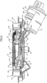
- the brake cable 37 is configured to be pulled by a motive force exerted by an electric actuator 38
- the electric actuator 38 includes a screw shaft 39 as a drive shaft coupled to the brake cable 37, an actuator case 40 configured to support the screw shaft 39 so as to allow reciprocating motion in the axial direction while inhibiting the rotation thereof, an electric motor 41 supported by the actuator case 40 so as to be freely rotatable in forward and reverse directions, and a motion conversion mechanism (not illustrated) interposed between the electric motor 41 and the screw shaft 39 and housed in the actuator case 40 while enabling conversion of the rotational motion generated by the electric motor 41 into the linear motion of the screw shaft 39.
- the back plate 13 is provided with a mounting cylinder portion 13a protruding therefrom, and a cylinder portion 40a provided on the actuator case 40 of the electric actuator 38 is fitted and secured to the mounting cylinder portion 13a.
- a boot 44 is provided between a portion of the screw shaft 39 protruding from the cylinder portion 40a and the insertion shaft part 39a so as to cover the portion of the screw shaft 39 protruding from the cylinder portion 40a.
- the engagement piece 36 secured to one end of the brake cable 37 is configured to be engaged with the lower end of the parking brake lever 34 while keeping the position with respect to the parking brake lever 34 constant.
- the engagement piece 36 integrally includes a shaft portion 36a to be inserted into a groove 46 formed at the lower end of the parking brake lever 34 and an engaging portion 36b continuing from the shaft portion 36a at a right angle so as to engage the lower end of the parking brake lever 34 from the opposite side of the brake cable 37 to form a substantially T-shape.
- a holding plate 45 which sandwiches the anchor block 21 with the back plate 13 is mounted to a lower portion of the back plate 13 with a pair of rivets 47 together with the anchor block 21, and a guide portion 45a configured to guide the brake cable 37 is integrally provided on the holding plate 45 so as to have a cross-sectional shape of substantially U-shape.
- a joint 48 is secured to the other end of the brake cable 37 having the engagement piece 36 at one end, for example, by caulking coupling, the screw shaft 39 of the electric actuator 38 and the joint 48 are coupled via an annular engaging member 49, which is repulsively expandable and contractible by an action of an external force.
- the engaging member 49 is a C-ring.
- the joint 48 is provided coaxially with an insertion hole 50 having a diameter smaller than an outer diameter of the engaging member 49 when the engaging member 49 is in the natural state, and a tapered hole 51 formed to increase in diameter as it goes outward in the axial direction and coaxially continuing from one end of the insertion hole 50.
- the joint 48 includes a mounting hole 52 continuing coaxially with the other end of the insertion hole 50 and formed to be smaller in diameter than the insertion hole 50, and the joint 48 is secured to the other end of the brake cable 37 by caulking with the other end of the brake cable 37 inserted into the mounting hole 52.
- An insertion shaft part 39a inserted from one end thereof into the insertion hole 50 is provided coaxially with the other one of the joint 48 and the screw shaft 39.
- a portion of the screw shaft 39 protruding from the boot 44 is inserted into the insertion hole 50 as the insertion shaft part 39a.
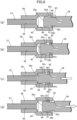
- the insertion shaft part 39a includes, on an outer periphery thereof, a first annular recess 53 capable of temporarily securing the engaging member 49 in the natural state as illustrated in Fig. 4 and allows the engaging member 49 in the temporarily secured state to be contracted in diameter until insertion into the insertion hole 50 is enabled.
- the insertion hole 50 includes a second annular recess 54 which rotatably engages the outer peripheral side of the engaging member 49 in an expanded state.
- the insertion shaft part 39a includes, on the outer periphery thereof, a third annular recess 55 continuing from the first annular recess 53 on a front side of the first annular recess 53 along the insertion direction of the insertion shaft part 39a into the insertion hole 50 and formed to be shallower than the first annular recess 53 while being capable of receiving the inner peripheral side of the engaging member 49.
- the engaging member 49 is engaged with both of the outer periphery of the insertion shaft part 39a and the inner periphery of the insertion hole 50 in this state, and thus the insertion shaft part 39a is allowed to rotate in the second annular recess 54, so that the brake cable 37 can be rotatably coupled to the screw shaft 39.
- the third annular recess 55 on the outer periphery of the insertion shaft part 39a receives the inner peripheral side of the engaging member 49 as illustrated in Fig. 5(c) , so that the insertion shaft part 39a is inhibited from being decoupled from the insertion hole 50.
- the insertion hole 50 is provided on one of the joint 48 secured to the brake cable 37 and the screw shaft 39 of the electric actuator 38, the insertion shaft part 39a inserted into the insertion hole 50 is coaxially provided on the other one of the joint 48 and the screw shaft 39, and the annular engaging member 49 that can be inserted into the insertion hole 50 together with the insertion shaft part 39a is interposed between the inner periphery of the insertion hole 50 and the outer periphery of the insertion shaft part 39a such that the joint 48 and the screw shaft 39 are coupled.
- the engaging member 49 is interposed between the inner periphery of the insertion hole 50 and the outer periphery of the insertion shaft part 39a, so that the joint 48 and the screw shaft 39 are coupled, whereby a coupling work between the screw shaft 39 and the brake cable 37 is facilitated for ease of assembly.
- the insertion hole 50 is formed to have a diameter smaller than an outer diameter of the engaging member 49 when the engaging member 49 repulsively expandable and contractible by an action of an external force is in a natural state, the tapered hole 51 formed to increase in diameter as it goes outward in the axial direction and coaxially continuing from one end of the insertion hole 50 is provided on one of the joint 48 and the screw shaft 39, the insertion shaft part 39a includes, on an outer periphery thereof, the first annular recess 53 capable of temporality securing the engaging member 49 in the natural state and allowing the engaging member 49 in the temporarily secured state to be contracted in diameter until insertion into the insertion hole 50 is enabled, and the insertion hole 50 includes the second annular recess 54 configured to rotatably engage the outer peripheral side of the engaging member 49 in the expanded state.
- the brake cable 37 can be rotatably coupled to the screw shaft 39 by a simple operation such as inserting the insertion shaft part 39a with the engaging member 49 temporarily secured thereto into the insertion hole 50, so that the brake cable 37 is free from twisting even when an engagement position of the engagement piece 36 at the one end of the brake cable 37 with the parking brake lever 34 is constant.
- the insertion shaft part 39a includes, on the outer periphery thereof, the third annular recess 55 continuing from the first annular recess 53 on the front side of the first annular recess 53 along the insertion direction of the insertion shaft part 39a into the insertion hole 50 and formed to be shallower than the first annular recess 53 while being capable of receiving the inner peripheral side of the engaging member 49. Therefore, even when an expanding force of the engaging member 49 is lowered, such an event that the entire engaging member 49 is accommodated in the first annular recess 53 and hence is decoupled from the second annular recess 54 is prevented from occurring, so that the engaging member 49 is inhibited from coming off.
- the engaging member 49 is an inexpensive C-ring, the cost reduction is achieved.
- a joint 58 is secured to the brake cable 37 for example, by caulking coupling, and a screw shaft 59 as a drive shaft provided on the electric actuator 38 (see the first embodiment) and the joint 58 are coupled via an annular engaging member 60, which is expandable and contractible by an action of an external force.
- the engaging member 60 is made of metal, for example, an iron-made C-ring, and includes a plurality of grooves 61 at regular intervals in a circumferential direction on an inner periphery or an outer periphery (outer periphery in this embodiment) of the engaging member 60 for facilitating expansion and contraction.
- the joint 58 is provided coaxially with a mounting hole 62 opened at one end thereof, a tapered hole 63 continuing, at a small diameter end, to the other end of the mounting hole 62, and an insertion hole 64 formed to have a diameter larger than the mounting hole 62 and continuing, at one end thereof, to a large diameter end of the tapered hole 63, and opening at the other end, and the joint 58 is secured to the brake cable 37 by caulking the joint 58 in a state in which the brake cable 37 is inserted into the mounting hole 62.
- the screw shaft 59 is provided coaxially with an insertion shaft part 59a inserted into the insertion hole 64.
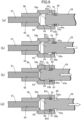
- the insertion shaft part 59a includes, on an outer periphery thereof, a fourth annular recess 65 having: a small diameter shaft section 65a, a first tapered portion 65b having a small diameter end coaxially continuing from a front end of the small diameter shaft section 65a along an insertion direction 66 of the insertion shaft part 59a into the insertion hole 64, a large diameter shaft section 65c coaxially continuing from a large diameter end of the first tapered portion 65b, and a second tapered portion 65d having a small diameter end coaxially continuing from a front end of the large diameter shaft section 65c along the insertion direction 66.
- the engaging member 60 which is expandable and contractible by an action of the external force may be temporarily secured to the small diameter shaft section 65a in a state of allowing displacement in a direction orthogonal to a center axis of the insertion shaft part 59a while allowing insertion into the insertion hole 64.
- the insertion hole 64 includes, on an inner periphery thereof, an annular locking recess 67, which allows engagement of part of the outer periphery of the engaging member 60 in a state of being temporality secured to the small diameter shaft section 65a according to the displacement of the engaging member 60 in the direction orthogonal to the center axis of the insertion shaft part 59a and allows engagement of the entire outer periphery of the engaging member 60 in a state of being fitted to the large diameter shaft section 65c.
- an inner diameter Da of the engaging member 60 in a natural state without being temporarily secured to the small diameter shaft section 65a of the insertion shaft part 59a is set to be larger than an outer diameter Db of the small diameter shaft section 65a and smaller than an outer diameter Dd of the large diameter shaft section 65c (Db ⁇ Da ⁇ Dd), so that the engaging member 60 is expanded and contracted by exerting an external force so as to have a smaller outer diameter Dc than an inner diameter De of the insertion hole 64 (Dc ⁇ De), and is temporarily secured to the small diameter shaft section 65a as illustrated in Fig. 6(b) and Fig. 7 .
- the engaging member 60 drops under its own weight to the direction orthogonal to the center axis of the insertion shaft part 59a. Accordingly, part of the outer periphery of the engaging member 60 engages the locking recess 67, and when the insertion shaft part 59a is retracted in this state as illustrated in Fig. 8(d) , the engaging member 60 regulated in retraction movement by the engagement with the locking recess 67 is expanded in diameter by the abutment with the first tapered portion 65b, fitted to the large diameter shaft section 65c, and engaged with the locking recess 67.
- a regulating member 68 interposed between a rear end wall 65e and the joint 58 along the insertion direction 66 of the fourth annular recess 65 is fitted to the small diameter shaft section 65a in a state in which the engaging member 60 fitted to the large diameter shaft section 65c is engaged with the locking recess 67 as illustrated in Fig. 6(c) , and the regulating member 68 is an E-type retaining ring in this embodiment.
- the brake cable 37 can be rotatably coupled to the screw shaft 59 by a simple operation such as inserting the insertion shaft part 59a with the engaging member 60 temporarily secured thereto into the insertion hole 64 and then retracting the same, so that the brake cable 37 is free from twisting even when the engagement position of the engagement piece 36 (see first embodiment) at the one end of the brake cable 37 with the parking brake lever 34 (see first embodiment) is constant.
- the regulating member 68 interposed between the rear end wall 65e and the joint 58 along the insertion direction 66 of the fourth annular recess 65 is fitted to the small diameter shaft section 65a in a state in which the engaging member 60 fitted to the large diameter shaft section 65c is engaged with the locking recess 67, the insertion shaft part 59a is prevented from unintentionally entering the insertion hole 64 in a state in which the insertion shaft part 59a and the joint 58 are coupled via the engaging member 60, so that the engaging member 60 may be prevented from becoming a state of being fitted to the small diameter shaft section 65a.
- the cost reduction may be achieved by employing an inexpensive E-type retaining ring for the regulating member 68.
- Fig. 9 a third embodiment of the present invention will be described. Parts corresponding to the second embodiment illustrated in Fig. 6 to Fig. 8 are only illustrated with the same reference numerals, and detailed description will be omitted.
- the joint 58 secured to the brake cable 37 and the insertion shaft part 59a of the screw shaft 59 are coupled via an annular engaging member 70 repulsively expandable and contractible by an action of an external force, and the engaging member 70 is a C-ring.
- the engaging member 70 is temporarily secured to the small diameter shaft section 65a of the fourth annular recess 65 formed on the outer periphery of the insertion shaft part 59a in a state of having a maximum outer diameter larger than an inner diameter of the insertion hole 64 formed in the joint 58 in a natural state and capable of contracting in diameter when inserted into the insertion hole 64.
- the locking recess 67 formed on an inner periphery of the insertion hole 64 allows engagement of at lest part of an outer periphery of the engaging member 70 by the engaging member 70 in a state of being temporarily secured to the small diameter shaft section 65a restoring from the state of being contracted in diameter to the natural state, and can engage the entire outer periphery of the engaging member 70 in a state of being fitted to the large diameter shaft section 65c of the fourth annular recess 65.
- the engaging member 70 is expanded in diameter so as to repulsively restore from the state of being contracted in diameter to the natural state, whereby at least part of the engaging member 70 engages the locking recess 67.
- the engaging member 70 drops under its own weight in a direction orthogonal to the center axis of the insertion shaft part 59a, whereby part of the outer periphery of the engaging member 70 engages the locking recess 67.
- the engaging member 70 regulated in retraction movement by the engagement with the locking recess 67 is expanded in diameter by the abutment with the first tapered portion 65b, fitted to the large diameter shaft section 65c, and engaged with the locking recess 67.
- the contraction in diameter of the engaging member 70 engaged with the locking recess 67 is inhibited, and the engaging member 70 engages with both of the outer periphery of the insertion shaft part 59a and the inner periphery of the insertion hole 64, so that the engaging member 70 is allowed to rotate in the locking recess 67.
- the regulating member 68 (see the second embodiment), which is an E-type retaining ring in the same manner as the second embodiment described above, is fitted to the small diameter shaft section 65a in a state in which the engaging member 70 fitted to the large diameter shaft section 65c is engaged with the locking recess 67.
- the same effects as the second embodiment are achieved with a simple operation such as inserting the insertion shaft part 59a on which the engaging member 70 is temporarily secured into the insertion hole 64 and then retracting the same.
Landscapes
- Engineering & Computer Science (AREA)
- General Engineering & Computer Science (AREA)
- Mechanical Engineering (AREA)
- Transportation (AREA)
- Braking Arrangements (AREA)
- Braking Systems And Boosters (AREA)
- Snaps, Bayonet Connections, Set Pins, And Snap Rings (AREA)
Applications Claiming Priority (2)
| Application Number | Priority Date | Filing Date | Title |
|---|---|---|---|
| JP2018187233 | 2018-10-02 | ||
| PCT/JP2019/037607 WO2020071211A1 (ja) | 2018-10-02 | 2019-09-25 | 電動パーキングブレーキ装置 |
Publications (3)
| Publication Number | Publication Date |
|---|---|
| EP3862590A1 EP3862590A1 (en) | 2021-08-11 |
| EP3862590A4 EP3862590A4 (en) | 2022-06-22 |
| EP3862590B1 true EP3862590B1 (en) | 2024-05-08 |
Family
ID=70054997
Family Applications (1)
| Application Number | Title | Priority Date | Filing Date |
|---|---|---|---|
| EP19868445.8A Active EP3862590B1 (en) | 2018-10-02 | 2019-09-25 | Electric parking brake device |
Country Status (3)
| Country | Link |
|---|---|
| EP (1) | EP3862590B1 (https=) |
| JP (1) | JP7265556B2 (https=) |
| WO (1) | WO2020071211A1 (https=) |
Families Citing this family (2)
| Publication number | Priority date | Publication date | Assignee | Title |
|---|---|---|---|---|
| FR3130000B1 (fr) * | 2021-12-03 | 2024-02-02 | Hitachi Astemo France | Actionneur électrique pour un frein de véhicule automobile comprenant un dispositif vis-écrou |
| JP2024142702A (ja) * | 2023-03-30 | 2024-10-11 | 株式会社アドヴィックス | 電動シリンダ装置及びブレーキ液圧制御装置 |
Family Cites Families (5)
| Publication number | Priority date | Publication date | Assignee | Title |
|---|---|---|---|---|
| JP5027940B2 (ja) * | 2004-06-30 | 2012-09-19 | 株式会社ハイレックスコーポレーション | 電動式のケーブル駆動装置および電動ブレーキ装置 |
| DE102004054864A1 (de) * | 2004-11-12 | 2006-05-24 | Ims Gear Gmbh | Spindel |
| JP5055014B2 (ja) * | 2007-05-08 | 2012-10-24 | 株式会社ハイレックスコーポレーション | インナーケーブルの連結解除機構およびそれを用いたケーブル駆動装置 |
| JP6576696B2 (ja) | 2015-06-01 | 2019-09-18 | 豊生ブレーキ工業株式会社 | 電動式ドラムブレーキ |
| US11002326B2 (en) * | 2016-08-31 | 2021-05-11 | Mando Corporation | Electronic parking brake |
-
2019
- 2019-09-25 JP JP2020550338A patent/JP7265556B2/ja active Active
- 2019-09-25 EP EP19868445.8A patent/EP3862590B1/en active Active
- 2019-09-25 WO PCT/JP2019/037607 patent/WO2020071211A1/ja not_active Ceased
Also Published As
| Publication number | Publication date |
|---|---|
| EP3862590A4 (en) | 2022-06-22 |
| JPWO2020071211A1 (ja) | 2021-09-02 |
| EP3862590A1 (en) | 2021-08-11 |
| WO2020071211A1 (ja) | 2020-04-09 |
| JP7265556B2 (ja) | 2023-04-26 |
Similar Documents
| Publication | Publication Date | Title |
|---|---|---|
| JP5960534B2 (ja) | ドラムブレーキ式電動駐車ブレーキ装置 | |
| US7073636B2 (en) | Disk brake with mechanical self-boosting | |
| EP3426943B1 (en) | Spindle nut assembly having multiple stop cams | |
| EP3862590B1 (en) | Electric parking brake device | |
| JP2017502228A (ja) | 不可逆なねじナットシステムを有するアクチュエータ、ドラムブレーキ、およびこれを備えるブレーキ装置 | |
| US3966028A (en) | Automatic brake adjusting mechanism | |
| DE10126556A1 (de) | Motorbetriebene Scheibenbremse | |
| CN109114133B (zh) | 鼓式制动装置 | |
| JP7529831B2 (ja) | 電動パーキングブレーキ装置 | |
| US20110127130A1 (en) | Mechanical drum brake | |
| JPS604382B2 (ja) | 円板ブレ−キ用自動弛み調節装置 | |
| US11867245B2 (en) | Electric parking brake device | |
| JP2019070405A (ja) | 電動パーキングブレーキ装置 | |
| JP2015152044A (ja) | 電動駐車ブレーキ | |
| JP6595471B2 (ja) | シンプレックス・モードでの且つ/又はサーボデュアル・モードでのドラム・ブレーキ動作 | |
| JP7451496B2 (ja) | 電動パーキングブレーキ装置 | |
| EP3998415B1 (en) | Vehicle drum brake | |
| US4392558A (en) | Actuator mechanisms for vehicle brakes | |
| WO2013035626A1 (ja) | ドラムブレーキ装置 | |
| US3261435A (en) | Brake adjuster | |
| JP5960535B2 (ja) | ドラムブレーキ式電動駐車ブレーキ装置用ケーブル接続装置 | |
| JP7037518B2 (ja) | 車両用ドラムブレーキ | |
| JP7526254B2 (ja) | 電動パーキングブレーキ装置 | |
| CN1003883B (zh) | 刹车致动器 | |
| JP2017141937A (ja) | ドラムブレーキ装置 |
Legal Events
| Date | Code | Title | Description |
|---|---|---|---|
| STAA | Information on the status of an ep patent application or granted ep patent |
Free format text: STATUS: THE INTERNATIONAL PUBLICATION HAS BEEN MADE |
|
| PUAI | Public reference made under article 153(3) epc to a published international application that has entered the european phase |
Free format text: ORIGINAL CODE: 0009012 |
|
| STAA | Information on the status of an ep patent application or granted ep patent |
Free format text: STATUS: REQUEST FOR EXAMINATION WAS MADE |
|
| 17P | Request for examination filed |
Effective date: 20210331 |
|
| AK | Designated contracting states |
Kind code of ref document: A1 Designated state(s): AL AT BE BG CH CY CZ DE DK EE ES FI FR GB GR HR HU IE IS IT LI LT LU LV MC MK MT NL NO PL PT RO RS SE SI SK SM TR |
|
| DAV | Request for validation of the european patent (deleted) | ||
| DAX | Request for extension of the european patent (deleted) | ||
| A4 | Supplementary search report drawn up and despatched |
Effective date: 20220520 |
|
| RIC1 | Information provided on ipc code assigned before grant |
Ipc: F16D 125/40 20120101ALN20220516BHEP Ipc: F16D 51/22 20060101ALI20220516BHEP Ipc: F16D 125/62 20120101ALI20220516BHEP Ipc: F16D 121/24 20120101ALI20220516BHEP Ipc: F16D 65/22 20060101ALI20220516BHEP Ipc: F16B 21/18 20060101ALI20220516BHEP Ipc: B60T 13/74 20060101AFI20220516BHEP |
|
| REG | Reference to a national code |
Ref country code: DE Ref legal event code: R079 Free format text: PREVIOUS MAIN CLASS: F16D0065220000 Ipc: B60T0013740000 Ref document number: 602019052079 Country of ref document: DE |
|
| GRAP | Despatch of communication of intention to grant a patent |
Free format text: ORIGINAL CODE: EPIDOSNIGR1 |
|
| STAA | Information on the status of an ep patent application or granted ep patent |
Free format text: STATUS: GRANT OF PATENT IS INTENDED |
|
| RIC1 | Information provided on ipc code assigned before grant |
Ipc: F16D 125/40 20120101ALN20231221BHEP Ipc: F16D 51/22 20060101ALI20231221BHEP Ipc: F16D 125/62 20120101ALI20231221BHEP Ipc: F16D 121/24 20120101ALI20231221BHEP Ipc: F16D 65/22 20060101ALI20231221BHEP Ipc: F16B 21/18 20060101ALI20231221BHEP Ipc: B60T 13/74 20060101AFI20231221BHEP |
|
| INTG | Intention to grant announced |
Effective date: 20240119 |
|
| GRAS | Grant fee paid |
Free format text: ORIGINAL CODE: EPIDOSNIGR3 |
|
| GRAA | (expected) grant |
Free format text: ORIGINAL CODE: 0009210 |
|
| STAA | Information on the status of an ep patent application or granted ep patent |
Free format text: STATUS: THE PATENT HAS BEEN GRANTED |
|
| AK | Designated contracting states |
Kind code of ref document: B1 Designated state(s): AL AT BE BG CH CY CZ DE DK EE ES FI FR GB GR HR HU IE IS IT LI LT LU LV MC MK MT NL NO PL PT RO RS SE SI SK SM TR |
|
| REG | Reference to a national code |
Ref country code: GB Ref legal event code: FG4D |
|
| REG | Reference to a national code |
Ref country code: CH Ref legal event code: EP |
|
| REG | Reference to a national code |
Ref country code: DE Ref legal event code: R096 Ref document number: 602019052079 Country of ref document: DE |
|
| REG | Reference to a national code |
Ref country code: IE Ref legal event code: FG4D |
|
| REG | Reference to a national code |
Ref country code: LT Ref legal event code: MG9D |
|
| REG | Reference to a national code |
Ref country code: NL Ref legal event code: MP Effective date: 20240508 |
|
| PG25 | Lapsed in a contracting state [announced via postgrant information from national office to epo] |
Ref country code: IS Free format text: LAPSE BECAUSE OF FAILURE TO SUBMIT A TRANSLATION OF THE DESCRIPTION OR TO PAY THE FEE WITHIN THE PRESCRIBED TIME-LIMIT Effective date: 20240908 |
|
| PG25 | Lapsed in a contracting state [announced via postgrant information from national office to epo] |
Ref country code: BG Free format text: LAPSE BECAUSE OF FAILURE TO SUBMIT A TRANSLATION OF THE DESCRIPTION OR TO PAY THE FEE WITHIN THE PRESCRIBED TIME-LIMIT Effective date: 20240508 |
|
| PG25 | Lapsed in a contracting state [announced via postgrant information from national office to epo] |
Ref country code: HR Free format text: LAPSE BECAUSE OF FAILURE TO SUBMIT A TRANSLATION OF THE DESCRIPTION OR TO PAY THE FEE WITHIN THE PRESCRIBED TIME-LIMIT Effective date: 20240508 Ref country code: FI Free format text: LAPSE BECAUSE OF FAILURE TO SUBMIT A TRANSLATION OF THE DESCRIPTION OR TO PAY THE FEE WITHIN THE PRESCRIBED TIME-LIMIT Effective date: 20240508 |
|
| PG25 | Lapsed in a contracting state [announced via postgrant information from national office to epo] |
Ref country code: GR Free format text: LAPSE BECAUSE OF FAILURE TO SUBMIT A TRANSLATION OF THE DESCRIPTION OR TO PAY THE FEE WITHIN THE PRESCRIBED TIME-LIMIT Effective date: 20240809 |
|
| PG25 | Lapsed in a contracting state [announced via postgrant information from national office to epo] |
Ref country code: PT Free format text: LAPSE BECAUSE OF FAILURE TO SUBMIT A TRANSLATION OF THE DESCRIPTION OR TO PAY THE FEE WITHIN THE PRESCRIBED TIME-LIMIT Effective date: 20240909 |
|
| REG | Reference to a national code |
Ref country code: AT Ref legal event code: MK05 Ref document number: 1684762 Country of ref document: AT Kind code of ref document: T Effective date: 20240508 |
|
| PG25 | Lapsed in a contracting state [announced via postgrant information from national office to epo] |
Ref country code: NL Free format text: LAPSE BECAUSE OF FAILURE TO SUBMIT A TRANSLATION OF THE DESCRIPTION OR TO PAY THE FEE WITHIN THE PRESCRIBED TIME-LIMIT Effective date: 20240508 |
|
| PG25 | Lapsed in a contracting state [announced via postgrant information from national office to epo] |
Ref country code: ES Free format text: LAPSE BECAUSE OF FAILURE TO SUBMIT A TRANSLATION OF THE DESCRIPTION OR TO PAY THE FEE WITHIN THE PRESCRIBED TIME-LIMIT Effective date: 20240508 |
|
| PG25 | Lapsed in a contracting state [announced via postgrant information from national office to epo] |
Ref country code: AT Free format text: LAPSE BECAUSE OF FAILURE TO SUBMIT A TRANSLATION OF THE DESCRIPTION OR TO PAY THE FEE WITHIN THE PRESCRIBED TIME-LIMIT Effective date: 20240508 |
|
| PG25 | Lapsed in a contracting state [announced via postgrant information from national office to epo] |
Ref country code: PL Free format text: LAPSE BECAUSE OF FAILURE TO SUBMIT A TRANSLATION OF THE DESCRIPTION OR TO PAY THE FEE WITHIN THE PRESCRIBED TIME-LIMIT Effective date: 20240508 |
|
| PG25 | Lapsed in a contracting state [announced via postgrant information from national office to epo] |
Ref country code: LV Free format text: LAPSE BECAUSE OF FAILURE TO SUBMIT A TRANSLATION OF THE DESCRIPTION OR TO PAY THE FEE WITHIN THE PRESCRIBED TIME-LIMIT Effective date: 20240508 |
|
| PG25 | Lapsed in a contracting state [announced via postgrant information from national office to epo] |
Ref country code: PT Free format text: LAPSE BECAUSE OF FAILURE TO SUBMIT A TRANSLATION OF THE DESCRIPTION OR TO PAY THE FEE WITHIN THE PRESCRIBED TIME-LIMIT Effective date: 20240909 Ref country code: PL Free format text: LAPSE BECAUSE OF FAILURE TO SUBMIT A TRANSLATION OF THE DESCRIPTION OR TO PAY THE FEE WITHIN THE PRESCRIBED TIME-LIMIT Effective date: 20240508 Ref country code: NO Free format text: LAPSE BECAUSE OF FAILURE TO SUBMIT A TRANSLATION OF THE DESCRIPTION OR TO PAY THE FEE WITHIN THE PRESCRIBED TIME-LIMIT Effective date: 20240808 Ref country code: NL Free format text: LAPSE BECAUSE OF FAILURE TO SUBMIT A TRANSLATION OF THE DESCRIPTION OR TO PAY THE FEE WITHIN THE PRESCRIBED TIME-LIMIT Effective date: 20240508 Ref country code: LV Free format text: LAPSE BECAUSE OF FAILURE TO SUBMIT A TRANSLATION OF THE DESCRIPTION OR TO PAY THE FEE WITHIN THE PRESCRIBED TIME-LIMIT Effective date: 20240508 Ref country code: IS Free format text: LAPSE BECAUSE OF FAILURE TO SUBMIT A TRANSLATION OF THE DESCRIPTION OR TO PAY THE FEE WITHIN THE PRESCRIBED TIME-LIMIT Effective date: 20240908 Ref country code: HR Free format text: LAPSE BECAUSE OF FAILURE TO SUBMIT A TRANSLATION OF THE DESCRIPTION OR TO PAY THE FEE WITHIN THE PRESCRIBED TIME-LIMIT Effective date: 20240508 Ref country code: GR Free format text: LAPSE BECAUSE OF FAILURE TO SUBMIT A TRANSLATION OF THE DESCRIPTION OR TO PAY THE FEE WITHIN THE PRESCRIBED TIME-LIMIT Effective date: 20240809 Ref country code: FI Free format text: LAPSE BECAUSE OF FAILURE TO SUBMIT A TRANSLATION OF THE DESCRIPTION OR TO PAY THE FEE WITHIN THE PRESCRIBED TIME-LIMIT Effective date: 20240508 Ref country code: ES Free format text: LAPSE BECAUSE OF FAILURE TO SUBMIT A TRANSLATION OF THE DESCRIPTION OR TO PAY THE FEE WITHIN THE PRESCRIBED TIME-LIMIT Effective date: 20240508 Ref country code: BG Free format text: LAPSE BECAUSE OF FAILURE TO SUBMIT A TRANSLATION OF THE DESCRIPTION OR TO PAY THE FEE WITHIN THE PRESCRIBED TIME-LIMIT Effective date: 20240508 Ref country code: AT Free format text: LAPSE BECAUSE OF FAILURE TO SUBMIT A TRANSLATION OF THE DESCRIPTION OR TO PAY THE FEE WITHIN THE PRESCRIBED TIME-LIMIT Effective date: 20240508 Ref country code: RS Free format text: LAPSE BECAUSE OF FAILURE TO SUBMIT A TRANSLATION OF THE DESCRIPTION OR TO PAY THE FEE WITHIN THE PRESCRIBED TIME-LIMIT Effective date: 20240808 |
|
| PG25 | Lapsed in a contracting state [announced via postgrant information from national office to epo] |
Ref country code: DK Free format text: LAPSE BECAUSE OF FAILURE TO SUBMIT A TRANSLATION OF THE DESCRIPTION OR TO PAY THE FEE WITHIN THE PRESCRIBED TIME-LIMIT Effective date: 20240508 |
|
| PG25 | Lapsed in a contracting state [announced via postgrant information from national office to epo] |
Ref country code: EE Free format text: LAPSE BECAUSE OF FAILURE TO SUBMIT A TRANSLATION OF THE DESCRIPTION OR TO PAY THE FEE WITHIN THE PRESCRIBED TIME-LIMIT Effective date: 20240508 |
|
| PG25 | Lapsed in a contracting state [announced via postgrant information from national office to epo] |
Ref country code: CZ Free format text: LAPSE BECAUSE OF FAILURE TO SUBMIT A TRANSLATION OF THE DESCRIPTION OR TO PAY THE FEE WITHIN THE PRESCRIBED TIME-LIMIT Effective date: 20240508 |
|
| PG25 | Lapsed in a contracting state [announced via postgrant information from national office to epo] |
Ref country code: SK Free format text: LAPSE BECAUSE OF FAILURE TO SUBMIT A TRANSLATION OF THE DESCRIPTION OR TO PAY THE FEE WITHIN THE PRESCRIBED TIME-LIMIT Effective date: 20240508 Ref country code: RO Free format text: LAPSE BECAUSE OF FAILURE TO SUBMIT A TRANSLATION OF THE DESCRIPTION OR TO PAY THE FEE WITHIN THE PRESCRIBED TIME-LIMIT Effective date: 20240508 |
|
| PG25 | Lapsed in a contracting state [announced via postgrant information from national office to epo] |
Ref country code: SM Free format text: LAPSE BECAUSE OF FAILURE TO SUBMIT A TRANSLATION OF THE DESCRIPTION OR TO PAY THE FEE WITHIN THE PRESCRIBED TIME-LIMIT Effective date: 20240508 |
|
| PG25 | Lapsed in a contracting state [announced via postgrant information from national office to epo] |
Ref country code: SM Free format text: LAPSE BECAUSE OF FAILURE TO SUBMIT A TRANSLATION OF THE DESCRIPTION OR TO PAY THE FEE WITHIN THE PRESCRIBED TIME-LIMIT Effective date: 20240508 Ref country code: SK Free format text: LAPSE BECAUSE OF FAILURE TO SUBMIT A TRANSLATION OF THE DESCRIPTION OR TO PAY THE FEE WITHIN THE PRESCRIBED TIME-LIMIT Effective date: 20240508 Ref country code: RO Free format text: LAPSE BECAUSE OF FAILURE TO SUBMIT A TRANSLATION OF THE DESCRIPTION OR TO PAY THE FEE WITHIN THE PRESCRIBED TIME-LIMIT Effective date: 20240508 Ref country code: EE Free format text: LAPSE BECAUSE OF FAILURE TO SUBMIT A TRANSLATION OF THE DESCRIPTION OR TO PAY THE FEE WITHIN THE PRESCRIBED TIME-LIMIT Effective date: 20240508 Ref country code: DK Free format text: LAPSE BECAUSE OF FAILURE TO SUBMIT A TRANSLATION OF THE DESCRIPTION OR TO PAY THE FEE WITHIN THE PRESCRIBED TIME-LIMIT Effective date: 20240508 Ref country code: CZ Free format text: LAPSE BECAUSE OF FAILURE TO SUBMIT A TRANSLATION OF THE DESCRIPTION OR TO PAY THE FEE WITHIN THE PRESCRIBED TIME-LIMIT Effective date: 20240508 |
|
| PG25 | Lapsed in a contracting state [announced via postgrant information from national office to epo] |
Ref country code: IT Free format text: LAPSE BECAUSE OF FAILURE TO SUBMIT A TRANSLATION OF THE DESCRIPTION OR TO PAY THE FEE WITHIN THE PRESCRIBED TIME-LIMIT Effective date: 20240508 |
|
| REG | Reference to a national code |
Ref country code: DE Ref legal event code: R097 Ref document number: 602019052079 Country of ref document: DE |
|
| PLBE | No opposition filed within time limit |
Free format text: ORIGINAL CODE: 0009261 |
|
| STAA | Information on the status of an ep patent application or granted ep patent |
Free format text: STATUS: NO OPPOSITION FILED WITHIN TIME LIMIT |
|
| 26N | No opposition filed |
Effective date: 20250211 |
|
| PG25 | Lapsed in a contracting state [announced via postgrant information from national office to epo] |
Ref country code: SI Free format text: LAPSE BECAUSE OF FAILURE TO SUBMIT A TRANSLATION OF THE DESCRIPTION OR TO PAY THE FEE WITHIN THE PRESCRIBED TIME-LIMIT Effective date: 20240508 Ref country code: MC Free format text: LAPSE BECAUSE OF FAILURE TO SUBMIT A TRANSLATION OF THE DESCRIPTION OR TO PAY THE FEE WITHIN THE PRESCRIBED TIME-LIMIT Effective date: 20240508 |
|
| REG | Reference to a national code |
Ref country code: CH Ref legal event code: PL |
|
| PG25 | Lapsed in a contracting state [announced via postgrant information from national office to epo] |
Ref country code: LU Free format text: LAPSE BECAUSE OF NON-PAYMENT OF DUE FEES Effective date: 20240925 |
|
| REG | Reference to a national code |
Ref country code: BE Ref legal event code: MM Effective date: 20240930 |
|
| PG25 | Lapsed in a contracting state [announced via postgrant information from national office to epo] |
Ref country code: BE Free format text: LAPSE BECAUSE OF NON-PAYMENT OF DUE FEES Effective date: 20240930 |
|
| PG25 | Lapsed in a contracting state [announced via postgrant information from national office to epo] |
Ref country code: CH Free format text: LAPSE BECAUSE OF NON-PAYMENT OF DUE FEES Effective date: 20240930 |
|
| PG25 | Lapsed in a contracting state [announced via postgrant information from national office to epo] |
Ref country code: IE Free format text: LAPSE BECAUSE OF NON-PAYMENT OF DUE FEES Effective date: 20240925 |
|
| PG25 | Lapsed in a contracting state [announced via postgrant information from national office to epo] |
Ref country code: SE Free format text: LAPSE BECAUSE OF FAILURE TO SUBMIT A TRANSLATION OF THE DESCRIPTION OR TO PAY THE FEE WITHIN THE PRESCRIBED TIME-LIMIT Effective date: 20240508 |
|
| PGFP | Annual fee paid to national office [announced via postgrant information from national office to epo] |
Ref country code: DE Payment date: 20250730 Year of fee payment: 7 |
|
| PGFP | Annual fee paid to national office [announced via postgrant information from national office to epo] |
Ref country code: GB Payment date: 20250807 Year of fee payment: 7 |
|
| PGFP | Annual fee paid to national office [announced via postgrant information from national office to epo] |
Ref country code: FR Payment date: 20250808 Year of fee payment: 7 |
|
| PG25 | Lapsed in a contracting state [announced via postgrant information from national office to epo] |
Ref country code: CY Free format text: LAPSE BECAUSE OF FAILURE TO SUBMIT A TRANSLATION OF THE DESCRIPTION OR TO PAY THE FEE WITHIN THE PRESCRIBED TIME-LIMIT; INVALID AB INITIO Effective date: 20190925 |
|
| PG25 | Lapsed in a contracting state [announced via postgrant information from national office to epo] |
Ref country code: HU Free format text: LAPSE BECAUSE OF FAILURE TO SUBMIT A TRANSLATION OF THE DESCRIPTION OR TO PAY THE FEE WITHIN THE PRESCRIBED TIME-LIMIT; INVALID AB INITIO Effective date: 20190925 |