EP3845189A2 - Dynamisches chirurgisches visualisierungssystem - Google Patents
Dynamisches chirurgisches visualisierungssystem Download PDFInfo
- Publication number
- EP3845189A2 EP3845189A2 EP20217602.0A EP20217602A EP3845189A2 EP 3845189 A2 EP3845189 A2 EP 3845189A2 EP 20217602 A EP20217602 A EP 20217602A EP 3845189 A2 EP3845189 A2 EP 3845189A2
- Authority
- EP
- European Patent Office
- Prior art keywords
- surgical
- image
- tissue
- visualization
- imaging
- Prior art date
- Legal status (The legal status is an assumption and is not a legal conclusion. Google has not performed a legal analysis and makes no representation as to the accuracy of the status listed.)
- Granted
Links
- 0 C[C@]1C(C2)C(C3)*(*)CCC3C2C1 Chemical compound C[C@]1C(C2)C(C3)*(*)CCC3C2C1 0.000 description 1
Images












Classifications
-
- G—PHYSICS
- G16—INFORMATION AND COMMUNICATION TECHNOLOGY [ICT] SPECIALLY ADAPTED FOR SPECIFIC APPLICATION FIELDS
- G16H—HEALTHCARE INFORMATICS, i.e. INFORMATION AND COMMUNICATION TECHNOLOGY [ICT] SPECIALLY ADAPTED FOR THE HANDLING OR PROCESSING OF MEDICAL OR HEALTHCARE DATA
- G16H30/00—ICT specially adapted for the handling or processing of medical images
- G16H30/40—ICT specially adapted for the handling or processing of medical images for processing medical images, e.g. editing
-
- A—HUMAN NECESSITIES
- A61—MEDICAL OR VETERINARY SCIENCE; HYGIENE
- A61B—DIAGNOSIS; SURGERY; IDENTIFICATION
- A61B1/00—Instruments for performing medical examinations of the interior of cavities or tubes of the body by visual or photographical inspection, e.g. endoscopes; Illuminating arrangements therefor
- A61B1/00002—Operational features of endoscopes
- A61B1/00004—Operational features of endoscopes characterised by electronic signal processing
- A61B1/00009—Operational features of endoscopes characterised by electronic signal processing of image signals during a use of endoscope
- A61B1/000094—Operational features of endoscopes characterised by electronic signal processing of image signals during a use of endoscope extracting biological structures
-
- A—HUMAN NECESSITIES
- A61—MEDICAL OR VETERINARY SCIENCE; HYGIENE
- A61B—DIAGNOSIS; SURGERY; IDENTIFICATION
- A61B1/00—Instruments for performing medical examinations of the interior of cavities or tubes of the body by visual or photographical inspection, e.g. endoscopes; Illuminating arrangements therefor
- A61B1/06—Instruments for performing medical examinations of the interior of cavities or tubes of the body by visual or photographical inspection, e.g. endoscopes; Illuminating arrangements therefor with illuminating arrangements
- A61B1/0638—Instruments for performing medical examinations of the interior of cavities or tubes of the body by visual or photographical inspection, e.g. endoscopes; Illuminating arrangements therefor with illuminating arrangements providing two or more wavelengths
-
- A—HUMAN NECESSITIES
- A61—MEDICAL OR VETERINARY SCIENCE; HYGIENE
- A61B—DIAGNOSIS; SURGERY; IDENTIFICATION
- A61B1/00—Instruments for performing medical examinations of the interior of cavities or tubes of the body by visual or photographical inspection, e.g. endoscopes; Illuminating arrangements therefor
- A61B1/06—Instruments for performing medical examinations of the interior of cavities or tubes of the body by visual or photographical inspection, e.g. endoscopes; Illuminating arrangements therefor with illuminating arrangements
- A61B1/0646—Instruments for performing medical examinations of the interior of cavities or tubes of the body by visual or photographical inspection, e.g. endoscopes; Illuminating arrangements therefor with illuminating arrangements with illumination filters
-
- A—HUMAN NECESSITIES
- A61—MEDICAL OR VETERINARY SCIENCE; HYGIENE
- A61B—DIAGNOSIS; SURGERY; IDENTIFICATION
- A61B18/00—Surgical instruments, devices or methods for transferring non-mechanical forms of energy to or from the body
- A61B18/04—Surgical instruments, devices or methods for transferring non-mechanical forms of energy to or from the body by heating
- A61B18/12—Surgical instruments, devices or methods for transferring non-mechanical forms of energy to or from the body by heating by passing a current through the tissue to be heated, e.g. high-frequency current
- A61B18/14—Probes or electrodes therefor
- A61B18/1442—Probes having pivoting end effectors, e.g. forceps
- A61B18/1445—Probes having pivoting end effectors, e.g. forceps at the distal end of a shaft, e.g. forceps or scissors at the end of a rigid rod
-
- A—HUMAN NECESSITIES
- A61—MEDICAL OR VETERINARY SCIENCE; HYGIENE
- A61B—DIAGNOSIS; SURGERY; IDENTIFICATION
- A61B34/00—Computer-aided surgery; Manipulators or robots specially adapted for use in surgery
- A61B34/10—Computer-aided planning, simulation or modelling of surgical operations
-
- A—HUMAN NECESSITIES
- A61—MEDICAL OR VETERINARY SCIENCE; HYGIENE
- A61B—DIAGNOSIS; SURGERY; IDENTIFICATION
- A61B34/00—Computer-aided surgery; Manipulators or robots specially adapted for use in surgery
- A61B34/25—User interfaces for surgical systems
-
- A—HUMAN NECESSITIES
- A61—MEDICAL OR VETERINARY SCIENCE; HYGIENE
- A61B—DIAGNOSIS; SURGERY; IDENTIFICATION
- A61B34/00—Computer-aided surgery; Manipulators or robots specially adapted for use in surgery
- A61B34/30—Surgical robots
-
- A—HUMAN NECESSITIES
- A61—MEDICAL OR VETERINARY SCIENCE; HYGIENE
- A61B—DIAGNOSIS; SURGERY; IDENTIFICATION
- A61B90/00—Instruments, implements or accessories specially adapted for surgery or diagnosis and not covered by any of the groups A61B1/00 - A61B50/00, e.g. for luxation treatment or for protecting wound edges
- A61B90/36—Image-producing devices or illumination devices not otherwise provided for
- A61B90/361—Image-producing devices, e.g. surgical cameras
-
- G—PHYSICS
- G01—MEASURING; TESTING
- G01B—MEASURING LENGTH, THICKNESS OR SIMILAR LINEAR DIMENSIONS; MEASURING ANGLES; MEASURING AREAS; MEASURING IRREGULARITIES OF SURFACES OR CONTOURS
- G01B11/00—Measuring arrangements characterised by the use of optical techniques
- G01B11/02—Measuring arrangements characterised by the use of optical techniques for measuring length, width or thickness
- G01B11/026—Measuring arrangements characterised by the use of optical techniques for measuring length, width or thickness by measuring distance between sensor and object
-
- G—PHYSICS
- G01—MEASURING; TESTING
- G01B—MEASURING LENGTH, THICKNESS OR SIMILAR LINEAR DIMENSIONS; MEASURING ANGLES; MEASURING AREAS; MEASURING IRREGULARITIES OF SURFACES OR CONTOURS
- G01B11/00—Measuring arrangements characterised by the use of optical techniques
- G01B11/24—Measuring arrangements characterised by the use of optical techniques for measuring contours or curvatures
- G01B11/25—Measuring arrangements characterised by the use of optical techniques for measuring contours or curvatures by projecting a pattern, e.g. one or more lines, moiré fringes on the object
- G01B11/2513—Measuring arrangements characterised by the use of optical techniques for measuring contours or curvatures by projecting a pattern, e.g. one or more lines, moiré fringes on the object with several lines being projected in more than one direction, e.g. grids, patterns
-
- G—PHYSICS
- G06—COMPUTING OR CALCULATING; COUNTING
- G06T—IMAGE DATA PROCESSING OR GENERATION, IN GENERAL
- G06T15/00—Three-dimensional [3D] image rendering
- G06T15/10—Geometric effects
- G06T15/20—Perspective computation
-
- G—PHYSICS
- G16—INFORMATION AND COMMUNICATION TECHNOLOGY [ICT] SPECIALLY ADAPTED FOR SPECIFIC APPLICATION FIELDS
- G16H—HEALTHCARE INFORMATICS, i.e. INFORMATION AND COMMUNICATION TECHNOLOGY [ICT] SPECIALLY ADAPTED FOR THE HANDLING OR PROCESSING OF MEDICAL OR HEALTHCARE DATA
- G16H20/00—ICT specially adapted for therapies or health-improving plans, e.g. for handling prescriptions, for steering therapy or for monitoring patient compliance
- G16H20/40—ICT specially adapted for therapies or health-improving plans, e.g. for handling prescriptions, for steering therapy or for monitoring patient compliance relating to mechanical, radiation or invasive therapies, e.g. surgery, laser therapy, dialysis or acupuncture
-
- A—HUMAN NECESSITIES
- A61—MEDICAL OR VETERINARY SCIENCE; HYGIENE
- A61B—DIAGNOSIS; SURGERY; IDENTIFICATION
- A61B17/00—Surgical instruments, devices or methods
- A61B17/32—Surgical cutting instruments
- A61B17/320068—Surgical cutting instruments using mechanical vibrations, e.g. ultrasonic
-
- A—HUMAN NECESSITIES
- A61—MEDICAL OR VETERINARY SCIENCE; HYGIENE
- A61B—DIAGNOSIS; SURGERY; IDENTIFICATION
- A61B18/00—Surgical instruments, devices or methods for transferring non-mechanical forms of energy to or from the body
- A61B18/04—Surgical instruments, devices or methods for transferring non-mechanical forms of energy to or from the body by heating
- A61B18/12—Surgical instruments, devices or methods for transferring non-mechanical forms of energy to or from the body by heating by passing a current through the tissue to be heated, e.g. high-frequency current
- A61B18/14—Probes or electrodes therefor
-
- A—HUMAN NECESSITIES
- A61—MEDICAL OR VETERINARY SCIENCE; HYGIENE
- A61B—DIAGNOSIS; SURGERY; IDENTIFICATION
- A61B17/00—Surgical instruments, devices or methods
- A61B2017/00743—Type of operation; Specification of treatment sites
- A61B2017/00809—Lung operations
-
- A—HUMAN NECESSITIES
- A61—MEDICAL OR VETERINARY SCIENCE; HYGIENE
- A61B—DIAGNOSIS; SURGERY; IDENTIFICATION
- A61B18/00—Surgical instruments, devices or methods for transferring non-mechanical forms of energy to or from the body
- A61B2018/00571—Surgical instruments, devices or methods for transferring non-mechanical forms of energy to or from the body for achieving a particular surgical effect
- A61B2018/00601—Cutting
-
- A—HUMAN NECESSITIES
- A61—MEDICAL OR VETERINARY SCIENCE; HYGIENE
- A61B—DIAGNOSIS; SURGERY; IDENTIFICATION
- A61B34/00—Computer-aided surgery; Manipulators or robots specially adapted for use in surgery
- A61B34/20—Surgical navigation systems; Devices for tracking or guiding surgical instruments, e.g. for frameless stereotaxis
- A61B2034/2046—Tracking techniques
- A61B2034/2051—Electromagnetic tracking systems
-
- A—HUMAN NECESSITIES
- A61—MEDICAL OR VETERINARY SCIENCE; HYGIENE
- A61B—DIAGNOSIS; SURGERY; IDENTIFICATION
- A61B34/00—Computer-aided surgery; Manipulators or robots specially adapted for use in surgery
- A61B34/20—Surgical navigation systems; Devices for tracking or guiding surgical instruments, e.g. for frameless stereotaxis
- A61B2034/2046—Tracking techniques
- A61B2034/2065—Tracking using image or pattern recognition
-
- A—HUMAN NECESSITIES
- A61—MEDICAL OR VETERINARY SCIENCE; HYGIENE
- A61B—DIAGNOSIS; SURGERY; IDENTIFICATION
- A61B34/00—Computer-aided surgery; Manipulators or robots specially adapted for use in surgery
- A61B34/30—Surgical robots
- A61B2034/302—Surgical robots specifically adapted for manipulations within body cavities, e.g. within abdominal or thoracic cavities
-
- A—HUMAN NECESSITIES
- A61—MEDICAL OR VETERINARY SCIENCE; HYGIENE
- A61B—DIAGNOSIS; SURGERY; IDENTIFICATION
- A61B90/00—Instruments, implements or accessories specially adapted for surgery or diagnosis and not covered by any of the groups A61B1/00 - A61B50/00, e.g. for luxation treatment or for protecting wound edges
- A61B90/30—Devices for illuminating a surgical field, the devices having an interrelation with other surgical devices or with a surgical procedure
- A61B2090/304—Devices for illuminating a surgical field, the devices having an interrelation with other surgical devices or with a surgical procedure using chemi-luminescent materials
-
- A—HUMAN NECESSITIES
- A61—MEDICAL OR VETERINARY SCIENCE; HYGIENE
- A61B—DIAGNOSIS; SURGERY; IDENTIFICATION
- A61B90/00—Instruments, implements or accessories specially adapted for surgery or diagnosis and not covered by any of the groups A61B1/00 - A61B50/00, e.g. for luxation treatment or for protecting wound edges
- A61B90/36—Image-producing devices or illumination devices not otherwise provided for
- A61B2090/364—Correlation of different images or relation of image positions in respect to the body
- A61B2090/365—Correlation of different images or relation of image positions in respect to the body augmented reality, i.e. correlating a live optical image with another image
-
- A—HUMAN NECESSITIES
- A61—MEDICAL OR VETERINARY SCIENCE; HYGIENE
- A61B—DIAGNOSIS; SURGERY; IDENTIFICATION
- A61B90/00—Instruments, implements or accessories specially adapted for surgery or diagnosis and not covered by any of the groups A61B1/00 - A61B50/00, e.g. for luxation treatment or for protecting wound edges
- A61B90/36—Image-producing devices or illumination devices not otherwise provided for
- A61B2090/364—Correlation of different images or relation of image positions in respect to the body
- A61B2090/367—Correlation of different images or relation of image positions in respect to the body creating a 3D dataset from 2D images using position information
-
- A—HUMAN NECESSITIES
- A61—MEDICAL OR VETERINARY SCIENCE; HYGIENE
- A61B—DIAGNOSIS; SURGERY; IDENTIFICATION
- A61B90/00—Instruments, implements or accessories specially adapted for surgery or diagnosis and not covered by any of the groups A61B1/00 - A61B50/00, e.g. for luxation treatment or for protecting wound edges
- A61B90/36—Image-producing devices or illumination devices not otherwise provided for
- A61B90/37—Surgical systems with images on a monitor during operation
- A61B2090/371—Surgical systems with images on a monitor during operation with simultaneous use of two cameras
-
- A—HUMAN NECESSITIES
- A61—MEDICAL OR VETERINARY SCIENCE; HYGIENE
- A61B—DIAGNOSIS; SURGERY; IDENTIFICATION
- A61B90/00—Instruments, implements or accessories specially adapted for surgery or diagnosis and not covered by any of the groups A61B1/00 - A61B50/00, e.g. for luxation treatment or for protecting wound edges
- A61B90/36—Image-producing devices or illumination devices not otherwise provided for
- A61B90/37—Surgical systems with images on a monitor during operation
- A61B2090/372—Details of monitor hardware
-
- A—HUMAN NECESSITIES
- A61—MEDICAL OR VETERINARY SCIENCE; HYGIENE
- A61B—DIAGNOSIS; SURGERY; IDENTIFICATION
- A61B90/00—Instruments, implements or accessories specially adapted for surgery or diagnosis and not covered by any of the groups A61B1/00 - A61B50/00, e.g. for luxation treatment or for protecting wound edges
- A61B90/36—Image-producing devices or illumination devices not otherwise provided for
- A61B90/37—Surgical systems with images on a monitor during operation
- A61B2090/373—Surgical systems with images on a monitor during operation using light, e.g. by using optical scanners
-
- A—HUMAN NECESSITIES
- A61—MEDICAL OR VETERINARY SCIENCE; HYGIENE
- A61B—DIAGNOSIS; SURGERY; IDENTIFICATION
- A61B90/00—Instruments, implements or accessories specially adapted for surgery or diagnosis and not covered by any of the groups A61B1/00 - A61B50/00, e.g. for luxation treatment or for protecting wound edges
- A61B90/36—Image-producing devices or illumination devices not otherwise provided for
- A61B90/37—Surgical systems with images on a monitor during operation
- A61B2090/374—NMR or MRI
-
- A—HUMAN NECESSITIES
- A61—MEDICAL OR VETERINARY SCIENCE; HYGIENE
- A61B—DIAGNOSIS; SURGERY; IDENTIFICATION
- A61B90/00—Instruments, implements or accessories specially adapted for surgery or diagnosis and not covered by any of the groups A61B1/00 - A61B50/00, e.g. for luxation treatment or for protecting wound edges
- A61B90/36—Image-producing devices or illumination devices not otherwise provided for
- A61B90/37—Surgical systems with images on a monitor during operation
- A61B2090/376—Surgical systems with images on a monitor during operation using X-rays, e.g. fluoroscopy
- A61B2090/3762—Surgical systems with images on a monitor during operation using X-rays, e.g. fluoroscopy using computed tomography systems [CT]
-
- A—HUMAN NECESSITIES
- A61—MEDICAL OR VETERINARY SCIENCE; HYGIENE
- A61B—DIAGNOSIS; SURGERY; IDENTIFICATION
- A61B90/00—Instruments, implements or accessories specially adapted for surgery or diagnosis and not covered by any of the groups A61B1/00 - A61B50/00, e.g. for luxation treatment or for protecting wound edges
- A61B90/39—Markers, e.g. radio-opaque or breast lesions markers
- A61B2090/3937—Visible markers
- A61B2090/3941—Photoluminescent markers
-
- A—HUMAN NECESSITIES
- A61—MEDICAL OR VETERINARY SCIENCE; HYGIENE
- A61B—DIAGNOSIS; SURGERY; IDENTIFICATION
- A61B5/00—Measuring for diagnostic purposes; Identification of persons
- A61B5/02—Detecting, measuring or recording for evaluating the cardiovascular system, e.g. pulse, heart rate, blood pressure or blood flow
-
- G—PHYSICS
- G01—MEASURING; TESTING
- G01J—MEASUREMENT OF INTENSITY, VELOCITY, SPECTRAL CONTENT, POLARISATION, PHASE OR PULSE CHARACTERISTICS OF INFRARED, VISIBLE OR ULTRAVIOLET LIGHT; COLORIMETRY; RADIATION PYROMETRY
- G01J3/00—Spectrometry; Spectrophotometry; Monochromators; Measuring colours
- G01J3/28—Investigating the spectrum
- G01J3/2823—Imaging spectrometer
- G01J2003/2826—Multispectral imaging, e.g. filter imaging
-
- G—PHYSICS
- G01—MEASURING; TESTING
- G01S—RADIO DIRECTION-FINDING; RADIO NAVIGATION; DETERMINING DISTANCE OR VELOCITY BY USE OF RADIO WAVES; LOCATING OR PRESENCE-DETECTING BY USE OF THE REFLECTION OR RERADIATION OF RADIO WAVES; ANALOGOUS ARRANGEMENTS USING OTHER WAVES
- G01S17/00—Systems using the reflection or reradiation of electromagnetic waves other than radio waves, e.g. lidar systems
- G01S17/88—Lidar systems specially adapted for specific applications
- G01S17/89—Lidar systems specially adapted for specific applications for mapping or imaging
- G01S17/894—Three-dimensional [3D] imaging with simultaneous measurement of time-of-flight at a two-dimensional [2D] array of receiver pixels, e.g. time-of-flight cameras or flash lidar
-
- G—PHYSICS
- G06—COMPUTING OR CALCULATING; COUNTING
- G06T—IMAGE DATA PROCESSING OR GENERATION, IN GENERAL
- G06T2200/00—Indexing scheme for image data processing or generation, in general
- G06T2200/24—Indexing scheme for image data processing or generation, in general involving graphical user interfaces [GUIs]
-
- G—PHYSICS
- G06—COMPUTING OR CALCULATING; COUNTING
- G06T—IMAGE DATA PROCESSING OR GENERATION, IN GENERAL
- G06T2210/00—Indexing scheme for image generation or computer graphics
- G06T2210/41—Medical
Definitions
- Scopes include, but are not limited to, arthroscopes, angioscopes, bronchoscopes, choledochoscopes, colonoscopes, cytoscopes, duodenoscopes, enteroscopes, esophagogastro-duodenoscopes (gastroscopes), endoscopes, laryngoscopes, nasopharyngo-neproscopes, sigmoidoscopes, thoracoscopes, ureteroscopes, and exoscopes.
- Imaging systems can be limited by the information that they are able to recognize and/or convey to the clinician(s). For example, certain concealed structures, physical contours, and/or dimensions within a three-dimensional space may be unrecognizable intraoperatively by certain imaging systems. Additionally, certain imaging systems may be incapable of communicating and/or conveying certain information to the clinician(s) intraoperatively.
- the control system allows the orientation of the surgical instrument (i.e., the shaft and/or end effector of the surgical instrument) currently displayed to the surgeon by the imaging system on a display screen to be utilized as a reference relative to a global coordinate system associated with the patient. Accordingly, the displayed orientation of the surgical instrument relative to the global coordinate system could be utilized to adjust the function of the controls on the surgical instrument, which would in turn cause the controls to correspond to the orientation displayed on the display screen.
- the surgical instrument i.e., the shaft and/or end effector of the surgical instrument
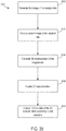
- the control circuit is configured to generate a first image of the surgical site based on the structured EMR received by the image sensor, receive a second image of the surgical site, align the first image and the second image, generate a three-dimensional representation of the surgical site based on the first image and the second image as aligned, display the three-dimensional representation on the display screen, receive a user selection to manipulate the three-dimensional representation, and update the three-dimensional representation as displayed on the displayed screen from a first state to a second state according to the user selection.
- FOV field of view
- the POV offered by the cameras could be non-ideal for performing particular steps of the surgical procedure (e.g., dissecting a vessel), hiding particular tissues and/or structures from view, and so on.
- the imaging system can create 3D representations of objects within the visualization field of the imaging system using aligned images and characterize the 3D shapes to allow users to make user selections to manipulate the displayed visualization with respect to the established coordinate system to better visualize the surgical site.
- the 3D representations can be generated from images generated from real-time sources (e.g., the imaging system) or non-real-time sources (e.g., CT scans or MRIs). Exemplary further details are discussed at paragraphs [0247] to [0262].
- a control system comprising an imaging system, a display screen, and a control circuit
- the imaging system comprises a first image sensor comprising a first field of view of a surgical site and a second image sensor comprising a second field of view of the surgical site.
- the first field of view and the second field of view at least partially overlap.
- the control circuit is operably in signal communication with the imaging system and the display screen.
- the present disclosure is directed to a surgical visualization platform that leverages "digital surgery" to obtain additional information about a patient's anatomy and/or a surgical procedure.
- the surgical visualization platform is further configured to convey data and/or information to one or more clinicians in a helpful manner.
- various aspects of the present disclosure provide improved visualization of the patient's anatomy and/or the surgical procedure.
- the information available to the clinician via the "naked eye” and/or an imaging system may provide an incomplete view of the surgical site.
- certain structures such as structures embedded or buried within an organ, can be at least partially concealed or hidden from view.
- certain dimensions and/or relative distances can be difficult to ascertain with existing sensor systems and/or difficult for the "naked eye” to perceive.
- certain structures can move preoperatively (e.g. before a surgical procedure but after a preoperative scan) and/or intraoperatively. In such instances, the clinician can be unable to accurately determine the location of a critical structure intraoperatively.
- a clinician's decision-making process can be inhibited. For example, a clinician may avoid certain areas in order to avoid inadvertent dissection of a critical structure; however, the avoided area may be unnecessarily large and/or at least partially misplaced. Due to uncertainty and/or overly/excessive exercises in caution, the clinician may not access certain desired regions. For example, excess caution may cause a clinician to leave a portion of a tumor and/or other undesirable tissue in an effort to avoid a critical structure even if the critical structure is not in the particular area and/or would not be negatively impacted by the clinician working in that particular area. In certain instances, surgical results can be improved with increased knowledge and/or certainty, which can allow a surgeon to be more accurate and, in certain instances, less conservative/more aggressive with respect to particular anatomical areas.
- a surgical visualization system for intraoperative identification and avoidance of critical structures.
- a surgical visualization system can provide valuable information to a clinician during a surgical procedure.
- the clinician can confidently maintain momentum throughout the surgical procedure knowing that the surgical visualization system is tracking a critical structure such as a ureter, specific nerves, and/or critical blood vessels, for example, which may be approached during dissection, for example.
- the surgical visualization system can provide an indication to the clinician in sufficient time for the clinician to pause and/or slow down the surgical procedure and evaluate the proximity to the critical structure to prevent inadvertent damage thereto.
- the surgical visualization system can provide an ideal, optimized, and/or customizable amount of information to the clinician to allow the clinician to move confidently and/or quickly through tissue while avoiding inadvertent damage to healthy tissue and/or critical structure(s) and, thus, to minimize the risk of harm resulting from the surgical procedure.
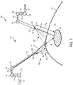
- FIG. 1 is a schematic of a surgical visualization system 100 according to at least one aspect of the present disclosure.
- the surgical visualization system 100 can create a visual representation of a critical structure 101 within an anatomical field.
- the surgical visualization system 100 can be used for clinical analysis and/or medical intervention, for example.
- the surgical visualization system 100 can be used intraoperatively to provide real-time, or near real-time, information to the clinician regarding proximity data, dimensions, and/or distances during a surgical procedure.
- the surgical visualization system 100 is configured for intraoperative identification of critical structure(s) and/or to facilitate the avoidance of the critical structure(s) 101 by a surgical device.
- a clinician can avoid maneuvering a surgical device around the critical structure 101 and/or a region in a predefined proximity of the critical structure 101 during a surgical procedure.
- the clinician can avoid dissection of and/or near a vein, artery, nerve, and/or vessel, for example, identified as the critical structure 101, for example.
- the critical structure 101 can be determined on a patient-by-patient and/or a procedure-by-procedure basis.
- the imaging device can include a camera or imaging sensor that is configured to detect visible light, spectral light waves (visible or invisible), and a structured light pattern (visible or invisible), for example.
- the imaging system can include an imaging device such as an endoscope, for example. Additionally or alternatively, the imaging system can include an imaging device such as an arthroscope, angioscope, bronchoscope, choledochoscope, colonoscope, cytoscope, duodenoscope, enteroscope, esophagogastro-duodenoscope (gastroscope), laryngoscope, nasopharyngo-neproscope, sigmoidoscope, thoracoscope, ureteroscope, or exoscope, for example. In other instances, such as in open surgery applications, the imaging system may not include a scope.
- the tissue identification subsystem can be achieved with a spectral imaging system.
- the spectral imaging system can rely on hyperspectral imaging, multispectral imaging, or selective spectral imaging, for example.
- Hyperspectral imaging of tissue is further described in U.S. Patent No. 9,274,047 , titled SYSTEM AND METHOD FOR GROSS ANATOMIC PATHOLOGY USING HYPERSPECTRAL IMAGING, issued March 1, 2016, which is incorporated by reference herein in its entirety.
- the distance determining system can be incorporated into the surface mapping system.
- structured light can be utilized to generate a three-dimensional virtual model of the visible surface and determine various distances with respect to the visible surface.
- the distance determining system can rely on time-of-flight measurements to determine one or more distances to the identified tissue (or other structures) at the surgical site.
- the heart of the camera 144 is the image sensor 135.
- image sensors 135 are solid-state electronic devices containing up to millions of discrete photodetector sites called pixels.
- the image sensor 135 technology falls into one of two categories: Charge-Coupled Device (CCD) and Complementary Metal Oxide Semiconductor (CMOS) imagers and more recently, short-wave infrared (SWIR) is an emerging technology in imaging.
- CCD Charge-Coupled Device
- CMOS Complementary Metal Oxide Semiconductor
- SWIR short-wave infrared
- Another type of image sensor 135 employs a hybrid CCD/CMOS architecture (sold under the name "sCMOS”) and consists of CMOS readout integrated circuits (ROICs) that are bump bonded to a CCD imaging substrate.
- sCMOS complementary metal Oxide Semiconductor
- the surface mapping logic 136 can determine the surface contours of the visible tissue based on reflected structured light. With time-of-flight measurements, the distance determining logic 141 can determine one or more distance(s) to the visible tissue and/or the critical structure 101. One or more outputs from the surface mapping logic 136, the tissue identification logic 140, and the distance determining logic 141, can be provided to the imaging logic 138, and combined, blended, and/or overlaid to be conveyed to a clinician via the display 146 of the imaging system 142.
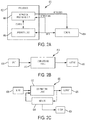
- the circuit may comprise a combination of a processor (e.g., processor 402 in FIG. 2A ) and a finite state machine to implement various processes herein.
- the finite state machine may comprise a combination of a combinational logic circuit (e.g., combinational logic circuit 410, FIG. 2B ) and the sequential logic circuit 420.
- the critical structure 101 can be an anatomical structure of interest.
- the critical structure 101 can be a ureter, an artery such as a superior mesenteric artery, a vein such as a portal vein, a nerve such as a phrenic nerve, and/or a tumor, among other anatomical structures.
- the critical structure 101 can be a foreign structure in the anatomical field, such as a surgical device, surgical fastener, clip, tack, bougie, band, and/or plate, for example.
- Example critical structures are further described herein and in the aforementioned U.S. Patent Applications, including U.S. Patent Application No. 16/128,192 , titled VISUALIZATION OF SURGICAL DEVICES, filed September 11, 2018, for example, which are incorporated by reference herein in their respective entireties.
- the imaging device 120 of the surgical visualization system 100 is configured to detect light at various wavelengths, such as, for example, visible light, spectral light waves (visible or invisible), and a structured light pattern (visible or invisible).
- the imaging device 120 may include a plurality of lenses, sensors, and/or receivers for detecting the different signals.
- the imaging device 120 can be a hyperspectral, multispectral, or selective spectral camera, as further described herein.
- the imaging device 120 can also include a waveform sensor 122 (such as a spectral image sensor, detector, and/or three-dimensional camera lens).
- the imaging device 120 also may include an optical waveform emitter 123 that is configured to emit electromagnetic radiation 124 (NIR photons) that can penetrate the surface 105 of the tissue 103 and reach the critical structure 101.
- the imaging device 120 and the optical waveform emitter 123 thereon can be positionable by the robotic arm 114.
- a corresponding waveform sensor 122 an image sensor, spectrometer, or vibrational sensor, for example
- the wavelengths of the electromagnetic radiation 124 emitted by the optical waveform emitter 123 can be configured to enable the identification of the type of anatomical and/or physical structure, such as the critical structure 101.
- the surgical visualization system 100 also may include the distance sensor system 104 configured to determine one or more distances at the surgical site.
- the time-of-flight distance sensor system 104 may be a time-of-flight distance sensor system that includes an emitter, such as the emitter 106, and a receiver 108, which can be positioned on the surgical device 102. In other instances, the time-of-flight emitter can be separate from the structured light emitter.
- the emitter 106 portion of the time-of-flight distance sensor system 104 may include a very tiny laser source and the receiver 108 portion of the time-of-flight distance sensor system 104 may include a matching sensor.
- the receiver 108 for the time-of-flight distance sensor system 104 can be mounted on a separate surgical device instead of the surgical device 102.
- the receiver 108 can be mounted on a cannula or trocar through which the surgical device 102 extends to reach the surgical site.
- the receiver 108 for the time-of-flight distance sensor system 104 can be mounted on a separate robotically-controlled arm (e.g. the robotic arm 114), on a movable arm that is operated by another robot, and/or to an operating room (OR) table or fixture.
- the position of the emitter 106 of the time-of-flight distance sensor system 104 can be controlled by the first robotic arm 112 and the position of the receiver 108 of the time-of-flight distance sensor system 104 can be controlled by the second robotic arm 114.
- the surgical visualization system 100 can be utilized apart from a robotic system. In such instances, the distance sensor system 104 can be independent of the robotic system.
- one or more of the robotic arms 112, 114 may be separate from a main robotic system used in the surgical procedure. At least one of the robotic arms 112, 114 can be positioned and registered to a particular coordinate system without a servomotor control. For example, a closed-loop control system and/or a plurality of sensors for the robotic arms 110 can control and/or register the position of the robotic arm(s) 112, 114 relative to the particular coordinate system. Similarly, the position of the surgical device 102 and the imaging device 120 can be registered relative to a particular coordinate system.
- the depth d A of the critical structure 101 relative to the surface 105 of the tissue 103 can be determined by triangulating from the distance d w and known positions of the emitter 106 on the surgical device 102 and the optical waveform emitter 123 on the imaging device 120 (and, thus, the known distance d x therebetween) to determine the distance d y , which is the sum of the distances d e and d A .
- various information regarding visible tissue, embedded critical structures, and surgical devices can be determined by utilizing a combination approach that incorporates one or more time-of-flight distance sensors, spectral imaging, and/or structured light arrays in combination with an image sensor configured to detect the spectral wavelengths and the structured light arrays.
- the image sensor can be configured to receive visible light and, thus, provide images of the surgical site to an imaging system.
- Logic or algorithms are employed to discern the information received from the time-of-flight sensors, spectral wavelengths, structured light, and visible light and render three-dimensional images of the surface tissue and underlying anatomical structures.
- the imaging device 120 can include multiple image sensors.
- the camera-to-critical structure distance d w can also be detected in one or more alternative ways.
- a fluoroscopy visualization technology such as fluorescent indosciedine green (ICG), for example, can be utilized to illuminate a critical structure 201, as shown in FIGS. 6-8 .
- a camera 220 can include two optical waveforms sensors 222, 224, which take simultaneous left-side and right-side images of the critical structure 201 ( FIG. 7A and 7B ). In such instances, the camera 220 can depict a glow of the critical structure 201 below the surface 205 of the tissue 203, and the distance d w can be determined by the known distance between the sensors 222 and 224.
- distances can be determined more accurately by utilizing more than one camera or by moving a camera between multiple locations.
- one camera can be controlled by a first robotic arm and a second camera by another robotic arm.
- one camera can be a follower camera on a follower arm, for example.
- the follower arm, and camera thereon, can be programmed to track the other camera and to maintain a particular distance and/or lens angle, for example.
- the surgical visualization system 100 may employ two separate waveform receivers (i.e. cameras/image sensors) to determine d w .
- two separate waveform receivers i.e. cameras/image sensors
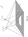
- the actual location can be triangulated from two separate cameras 320a, 320b at known locations.
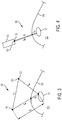
- a surgical visualization system may employ a dithering or moving camera 440 to determine the distance d w .
- the camera 440 is robotically-controlled such that the three-dimensional coordinates of the camera 440 at the different positions are known.
- the camera 440 can pivot at a cannula or patient interface.
- a critical structure 401 or the contents thereof e.g. a vessel or the contents of the vessel
- the actual location can be triangulated from the camera 440 moved rapidly between two or more known locations.
- the camera 440 is moved axially along an axis A.
- the camera 440 translates a distance d 1 closer to the critical structure 401 along the axis A to the location indicated as a location 440', such as by moving in and out on a robotic arm.
- the distance to the critical structure 401 can be calculated.
- a 4.28 mm axial translation (the distance d 1 ) can correspond to an angle ⁇ 1 of 6.28 degrees and an angle ⁇ 2 of 8.19 degrees.
- the camera 440 can rotate or sweep along an arc between different positions. Referring now to FIG.
- the camera 440 is moved axially along the axis A and is rotated an angle ⁇ 3 about the axis A.
- a pivot point 442 for rotation of the camera 440 is positioned at the cannula/patient interface.
- the camera 440 is translated and rotated to a location 440".
- a distance d 2 can be 9.01 mm, for example, and the angle ⁇ 3 can be 0.9 degrees, for example.
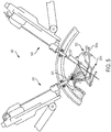
- FIG. 5 depicts a surgical visualization system 500, which is similar to the surgical visualization system 100 in many respects.
- the surgical visualization system 500 can be a further exemplification of the surgical visualization system 100.
- the surgical visualization system 500 includes a surgical device 502 and an imaging device 520.
- the imaging device 520 includes a spectral light emitter 523, which is configured to emit spectral light in a plurality of wavelengths to obtain a spectral image of hidden structures, for example.
- the imaging device 520 can also include a three-dimensional camera and associated electronic processing circuits in various instances.
- the surgical visualization system 500 is shown being utilized intraoperatively to identify and facilitate avoidance of certain critical structures, such as a ureter 501 a and vessels 501b in an organ 503 (the uterus in this example), that are not visible on the surface.
- the surgical visualization system 500 is configured to determine an emitter-to-tissue distance d e from an emitter 506 on the surgical device 502 to a surface 505 of the uterus 503 via structured light.
- the surgical visualization system 500 is configured to extrapolate a device-to-tissue distance d t from the surgical device 502 to the surface 505 of the uterus 503 based on the emitter-to-tissue distance d e .
- the surgical visualization system 500 is also configured to determine a tissue-to-ureter distance d A from the ureter 501a to the surface 505 and a camera-to ureter distance d w from the imaging device 520 to the ureter 501a. As described herein with respect to FIG.
- the surgical visualization system 500 can determine the distance d w with spectral imaging and time-of-flight sensors, for example. In various instances, the surgical visualization system 500 can determine (e.g. triangulate) the tissue-to-ureter distance d A (or depth) based on other distances and/or the surface mapping logic described herein.
- the control system 600 is a conversion system that integrates spectral signature tissue identification and structured light tissue positioning to identify critical structures, especially when those structures are obscured by other tissue, such as fat, connective tissue, blood, and/or other organs, for example.
- tissue variability such as differentiating tumors and/or non-healthy tissue from healthy tissue within an organ.
- the control system 600 is configured for implementing a hyperspectral imaging and visualization system in which a molecular response is utilized to detect and identify anatomy in a surgical field of view.
- the control system 600 includes a conversion logic circuit 648 to convert tissue data to surgeon usable information.
- the variable reflectance based on wavelengths with respect to obscuring material can be utilized to identify the critical structure in the anatomy.
- the control system 600 combines the identified spectral signature and the structural light data in an image.
- the control system 600 can be employed to create of three-dimensional data set for surgical use in a system with augmentation image overlays. Techniques can be employed both intraoperatively and preoperatively using additional visual information.
- the control system 600 is configured to provide warnings to a clinician when in the proximity of one or more critical structures.
- Various algorithms can be employed to guide robotic automation and semi-automated approaches based on the surgical procedure and proximity to the critical structure(s).
- a projected array of lights is employed to determine tissue shape and motion intraoperatively.
- flash Lidar may be utilized for surface mapping of the tissue.
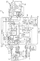
- the control system 600 includes a spectral control circuit 602.
- the spectral control circuit 602 can be a field programmable gate array (FPGA) or another suitable circuit configuration as described herein in connection with FIGS. 2A-2C , for example.
- the spectral control circuit 602 includes a processor 604 to receive video input signals from a video input processor 606.
- the processor 604 can be configured for hyperspectral processing and can utilize C/C++ code, for example.
- the video input processor 606 receives video-in of control (metadata) data such as shutter time, wave length, and sensor analytics, for example.
- the processor 604 is configured to process the video input signal from the video input processor 606 and provide a video output signal to a video output processor 608, which includes a hyperspectral video-out of interface control (metadata) data, for example.
- the video output processor 608 provides the video output signal to an image overlay controller 610.
- the video input processor 606 is coupled to a camera 612 at the patient side via a patient isolation circuit 614.
- the camera 612 includes a solid state image sensor 634.
- the patient isolation circuit can include a plurality of transformers so that the patient is isolated from other circuits in the system.
- the camera 612 receives intraoperative images through optics 632 and the image sensor 634.
- the image sensor 634 can include a CMOS image sensor, for example, or may include any of the image sensor technologies discussed herein in connection with FIG. 2 , for example.
- the camera 612 outputs images in 14 bit / pixel signals. It will be appreciated that higher or lower pixel resolutions may be employed without departing from the scope of the present disclosure.
- 13A is a graph 2300 depicting how the absorption coefficient of various biological materials varies across the EMR wavelength spectrum.
- the vertical axis 2303 represents absorption coefficient of the biological material (e.g., in cm -1 ) and the horizontal axis 2304 represents EMR wavelength (e.g., in ⁇ m).
- the imaging system 142 can be configured to tailor or update the displayed surgical site visualization according to the identified tissue and/or structure types.
- the imaging system 142 can display a margin 2330a associated with the tumor 2332 being visualized on a display screen (e.g., display 146).
- the margin 2330a can indicate the area or amount of tissue that should be excised to ensure complete removal of the tumor 2332.
- the control system 133 FIG. 2
- the imaging system 142 has identified multiple abnormalities 2338 within the FOV.
- a time-of-flight sensor system 1204 utilizing waves 1224a, 1224b, 1224c, 1225a, 1225b, 1225c is shown.
- the time-of-flight sensor system 1204 can be incorporated into the surgical visualization system 100 ( FIG. 1 ) in certain instances.
- the time-of-flight sensor system 1204 includes a waveform emitter 1206 and a waveform receiver 1208.
- the waveform emitter 1206 is positioned on a first surgical device 1202a
- the waveform receiver 1208 is positioned on a second surgical device 1202b.
- Knowledge of the positions of the emitter 1206 and the receiver 1208, as well as the time of the photon stream to target a certain tissue and the information received by the receiver 1208 of that particular response can allow a determination of the distances d 1a , d 2a , d 3a , d 1b , d 2b , d 2c .
- the distance to the obscured critical structures 1201a, 1201b can be triangulated using penetrating wavelengths. Because the speed of light is constant for any wavelength of visible or invisible light, the time-of-flight sensor system 1204 can determine the various distances.
- time-of-flight spectral waveforms are configured to determine the depth of the critical structure and/or the proximity of a surgical device to the critical structure.
- the various surgical visualization systems disclosed herein include surface mapping logic that is configured to create three-dimensional rendering of the surface of the visible tissue. In such instances, even when the visible tissue obstructs a critical structure, the clinician can be aware of the proximity (or lack thereof) of a surgical device to the critical structure. In one instances, the topography of the surgical site is provided on a monitor by the surface mapping logic. If the critical structure is close to the surface of the tissue, spectral imaging can convey the position of the critical structure to the clinician. For example, spectral imaging may detect structures within 5 or 10 mm of the surface.
- an alert can be provided to the clinician at a first distance (such as 10 mm, for example), and if the temperature of the tool is less than or equal to the predefined threshold, the alert can be provided to the clinician at a second distance (such as 5 mm, for example).
- the predefined thresholds and/or warning distances can be default settings and/or programmable by the clinician.
- a proximity alert can be linked to thermal measurements made by the tool itself, such as a thermocouple that measures the heat in a distal jaw of a monopolar or bipolar dissector or vessel sealer, for example.
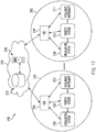
- a surgical system 2102 may include an M number of hubs 2106, an N number of visualization systems 2108, an O number of robotic systems 2110, and a P number of handheld intelligent surgical instruments 2112, where M, N, O, and P are integers greater than or equal to one.
- the situational awareness system can include a lookup table storing pre-characterized contextual information regarding a surgical procedure in association with one or more inputs (or ranges of inputs) corresponding to the contextual information.
- the lookup table can return the corresponding contextual information for the situational awareness system for controlling the modular devices 2402.
- the contextual information received by the situational awareness system of the surgical hub 2404 is associated with a particular control adjustment or set of control adjustments for one or more modular devices 2402.
- the situational awareness system includes a further machine learning system, lookup table, or other such system, which generates or retrieves one or more control adjustments for one or more modular devices 2402 when provided the contextual information as input.
- the surgical hub 2404 can be further configured to compare a physiologic measurement (e.g., blood pressure sensed by a BP monitor communicably connected to the surgical hub 2404) with the visual or image data of hemostasis (e.g., from a medical imaging device 124 ( FIG. 2 ) communicably coupled to the surgical hub 2404) to make a determination on the integrity of the staple line or tissue weld.
- a physiologic measurement e.g., blood pressure sensed by a BP monitor communicably connected to the surgical hub 2404
- the visual or image data of hemostasis e.g., from a medical imaging device 124 ( FIG. 2 ) communicably coupled to the surgical hub 2404
- the situational awareness system of the surgical hub 2404 can consider the physiological measurement data to provide additional context in analyzing the visualization data.
- the additional context can be useful when the visualization data may be inconclusive or incomplete on its own.
- Third step 2506 the medical personnel scan the patient band via a scanner that is communicably connected to the surgical hub 106, 206.
- the surgical hub 106, 206 can then confirm the patient's identity based on the scanned data.
- the staff members attach the EKG electrodes and other patient monitoring devices to the patient.
- the EKG electrodes and other patient monitoring devices are able to pair with the surgical hub 106, 206.
- the surgical hub 106, 206 begins receiving data from the patient monitoring devices, the surgical hub 106, 206 thus confirms that the patient is in the operating theater.
- the situational awareness system can be trained to recognize the positioning of the medical imaging device according to the visualization of the patient's anatomy.
- one technique for performing a VATS lobectomy utilizes a single medical imaging device, whereas another technique for performing a VATS segmentectomy utilizes multiple cameras.
- one technique for performing a VATS segmentectomy utilizes an infrared light source (which can be communicably coupled to the surgical hub as part of the visualization system) to visualize the segmental fissure, which is not utilized in a VATS lobectomy.
- the surgical hub 106, 206 can thereby determine the specific type of surgical procedure being performed and/or the technique being used for a particular type of surgical procedure.
- Tenth step 2520 the surgical team proceeds to the ligation step of the procedure.
- the surgical hub 106, 206 can infer that the surgeon is ligating arteries and veins because it receives data from the surgical stapling and cutting instrument indicating that the instrument is being fired. Similarly to the prior step, the surgical hub 106, 206 can derive this inference by cross-referencing the receipt of data from the surgical stapling and cutting instrument with the retrieved steps in the process.
- the surgical instrument can be a surgical tool mounted to a robotic arm of a robotic surgical system.
- tissue often moves and/or changes during a surgical procedure.
- the tissue is dynamic.
- the tissue may be distorted, stressed, or become otherwise deformed by a surgical fastening operation.
- the tissue may also be transected and/or certain portions and/or layers of tissue may be removed. Underlying tissue and/or structures may become exposed during the surgical procedure.
- embedded structures underlying the visible tissue and/or hidden tissue margins within an anatomical structure may also move.
- a resection margin may be concentrically positioned around a tumor prior to tissue deformation; however, as the anatomical structure is deformed during a surgical procedure, the resection margin may also become deformed.
- adjacent portions of tissue can shift, including those portions with previously-identified physical characteristics or properties.
- Imaging by a visualization system can be converted into measurable data and information for the clinician(s) and/or surgical hub(s).
- visualization can be utilized to analyze surgical device usage and to provide opportunities for improvement or device optimization in certain instances.
- situational awareness can inform the visualization system.
- a surgical system including a situational awareness module communicatively coupled to a visualization system, as described herein, can be configured to provide updated information, such as updated tissue characteristics and/or metadata, for example, to a clinician via a display during a surgical procedure.
- Updated visualization imaging or other data can be provided automatically based on input from the situational awareness module and/or can be suggested by the situational awareness module based on an awareness of the surgical procedure, patient, and/or tissue.
- Such a visualization system is adaptive to the surgical scenario.
- the visualization images can be updated in accordance with input from the situational awareness module.
- the situational awareness module can determine the type of surgical procedure, the step in the surgical procedure, the type(s) of tissue, and/or various tissue characteristics, as further described herein. Updates to the visualization images can be automated and/or recommended to a clinician based on inputs from the situational awareness module. For example, if the situational awareness module becomes aware that a staple line has been fired into tissue, the situational awareness module can order or suggest updating the visualization imaging to show the tissue compression along the staple line. As another example, if the situational awareness module becomes aware that visible tissue has shifted during a surgical procedure, the situational awareness module can order or suggest updating the visualization imaging to show the updated configuration of a resection margin. Additional surgical scenarios are contemplated and various examples are provided throughout the present disclosure.
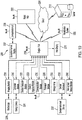
- the visualization system 6008 can be similar in many respects to the visualization system 100 ( FIG. 1 ) and the visualization system 2108 ( FIG. 17 ).
- the visualization system 6008 includes a memory 6034 communicatively coupled to the control circuit 6032.
- the visualization system 6008 also includes multiple light sources 6050, an imaging system 6042 having a camera 6044, a display 6046, and controls 6048.
- the camera 6044 includes at least one image sensor 6035.
- the adaptive visualization system 6008 can include multiple cameras, for example.
- the visualization system 6008 is configured to adapt in response to input from the hub 6006.
- the visualization system 6008 is an adaptive visualization system.
- the hub 6006 includes the situational awareness module 6007, which is configured to synthesize data from multiple sources to determine an appropriate response to a surgical event.
- the situational awareness module 6007 can determine the type of surgical procedure, step in the surgical procedure, type of tissue, and/or tissue characteristics, as further described herein.
- such a situational awareness module 6007 can recommend a particular course of action or possible choices to a system based on the synthesized data.
- a sensor system encompassing a plurality of sensors distributed throughout a surgical system can provide data, images, and/or other information to the situational awareness module 6007.
- Such a situational awareness module 6007 can be incorporated into a control unit of the surgical hub 6006, for example.
- the visualization system 6008 is configured to update or otherwise modify the visualization(s) provided to the clinician(s) based on the input from the situational awareness module 6007.
- the light sources 6050 can include at least one structured light source for determining the surface geometry and contours of an anatomical structure.
- 3Dlntegrated, Inc. (3Di) of Copenhagen, Denmark provides a platform based on structured light, deep learning, and structure from motion principles to obtain three-dimensional data in real-time.
- 3Di software can be utilized to determine the three-dimensional position of surgical tools, generate the three-dimensional reconstruction of surgical surfaces, and obtain coordinates for computer-driven surgery, for example.
- a structured light pattern utilizing a single imaging array can be utilized to determine surface contouring, for example. Reliance on a single structured light pattern can provide an incomplete digital model.
- Certain portions of a surface can be obstructed if there are surface irregularities, for example.
- multiple structured light arrays can be employed, such as multiple arrays on the same laparoscopy camera, for example, to generate a more complete digital model.
- the visualization system 6008, for example, can include multiple light sources in combination with structured light patterns to extrapolate additional aspects, characterizations, or metadata of the imaged tissue.
- the additional aspects can be tissue velocity, tissue distortion, tissue irregularity, tissue vascularization, and identification of an embedded structure within the anatomical structure, for example.
- Vascularization can be analyzed by tracking the underlying moving particles, for example.
- Doppler imaging may be used to determine the velocity flow of particles such as blood cells flowing within a blood vessel such as a vein, capillary, or artery. Doppler imaging may provide a direction and velocity of cell flow through the blood vessel.
- infrared (IR) absorption may identify the red blood cells as being oxygen-rich—thereby identifying the blood vessel as an artery-or oxygen-depleted—thereby identifying the blood vessel as a vein.
- IR infrared
- Tissue characterization is further described in U.S. Patent Application No. 15/940,722 , titled CHARACTERIZATION OF TISSUE IRREGULARITIES THROUGH THE USE OF MONO-CHROMATIC LIGHT REFRACTIVITY and U.S. Patent Application No.
- certain portions of the imaging frames with structured light can be utilized to add three-dimensional tissue variances. These portions can provide additional tissue characteristics and/or metadata of the imaged tissue.
- the structured light source can include a multi-source structured light.
- the light sources 6050 FIG. 22
- the use of coherent light can enable the differentiation and separation of the surface refractivity from the three-dimensional distortion of the structured light pattern.
- phase shift data from the multiple coherent light sources can be utilized to characterize tissue properties.
- sequential frames may be taken using alternating light wavelengths for each frame.
- a portion of the frames can be digitally removed from the three-dimensional surface mapping visualization. For example, ten frames for each of the sixty frames of each wavelength can be digitally removed. If the visualized tissue remains stationary throughout a group of frames, the digitally removed frames may be used to produce an averaged image.
- the digitally-removed frames may not be utilized for three-dimensional surface mapping, the surface refractivity (or other properties) of those portions can be utilized to determine additional tissue characteristics and/or metadata. Examples of such tissue characteristics may include, without limitation, a tissue composition and/or a tissue sub-structure orientation (for example, the underlying orientation of collagen or elastin fibers). Tissue characterization is further described in U.S.
- Patent Application No. 15/940,722 titled CHARACTERIZATION OF TISSUE IRREGULARITIES THROUGH THE USE OF MONO-CHROMATIC LIGHT REFRACTIVITY, filed March 29, 2018, which is incorporated by reference herein in its entirety.
- the light source 6050 can includes red, green, blue, infrared, and ultraviolet lasers. Multiple wavelengths can be utilized for certain light, such as infrared and/or ultraviolet, for example. In some aspects, multiple infrared light sources within the range of about 700 nm to about 1400 nm may be used. In some examples, the infrared light may have a wavelength of about 705 nm, about 730 nm, about 761 nm, about 780 nm, about 785 nm, about 800 nm, about 830 nm, 850 nm, 940 nm, 980 nm, 1064 nm, or 1370 nm.
- CMOS arrays and FPGA conversion circuits can be incorporated into the visualization system to acquire time-synced interrelated metadata about the imaged tissue.
- the resolution of an image obtained by a CMOS sensor can be enhanced by combining a multi-color structured light image received by the CMOS sensor with an image obtained by a higher resolution grey scale imaging sensor to enable the micronization of the specific array such that more than one array can be positioned on the same laparoscopy camera.
- the multiple arrays enable stereoscopic replication of the same image as well as independent FPGAs or independent sensors to monitor different aspects of the image or related metadata in real-time. Multi-array imaging is further described in U.S. Patent Application No. 15/940,742 , titled DUAL CMOS ARRAY IMAGING, filed March 29, 2018, which is incorporated by reference herein in its entirety.
- the visualization system 6108 is similar in many respects to the visualization system 6008 in FIG. 22 .
- the visualization system 6108 includes a structured light projector 6150 for projecting structured light patterns onto tissue T at a plurality of different wavelengths and a camera 6144 having at least one image sensor.
- the structured light projector 6150 and the camera 6144 are communicatively coupled to a control circuit, such as the control circuit 6032 ( FIG. 22 ).
- the camera 6144 is configured to detect imaging data from the structured light projector 6150 and convey the imaging data to the control circuit for processing.
- surface irregularities of the tissue T can be identified with the imaging data obtained by the camera 6144 and sent to the control circuit.
- the structured light pattern reflected from the surface of the tissue T may provide an incomplete picture of the surgical site due to irregularities along the surface of the tissue T in certain instances.
- the surface has one or more irregularities such as a tear, cut, and/or deformation that interferes with the structured light pattern
- the entire structured light pattern may not be reflected by the surface and, thus, may not be detected by the image sensor of the camera 6144.
- a surface deformation can cast a shadow that obstructs a portion of the structured light pattern.
- structured light patterns penetrating the surface of the tissue and reflected from a sub-surface thereof can be utilized to fill gaps in the three-dimensional digital rendering.
- one or more wavelengths of coherent light that penetrate the surface of the tissue can be utilized to determine the contours of the subsurface.
- the structured light pattern or patterns can be emitted at different wavelengths and captured by the image sensor.
- Certain subsurface light patterns may be digitally removed from the three-dimensional digital rendering; however, such patterns can be used to extrapolate the contours of the tissue surface. More specifically, the geometry of the tissue surface can be extrapolated from the curvature of one or more tissue sub-surfaces.
- the visualization system 6108 can be configured to identify the surface geometry of an organ 6160, such as a stomach, for example, as further described herein.
- irregularities 6164 on the surface of the organ 6160 can inhibit the generation of a complete three-dimensional model of the organ 6160.
- the irregularity 6164 which may be a scar or other tissue malformation, can block the structured light pattern emitted by the structured light projector 6150 from reaching portions of the tissue T surface.
- a pattern of structured light at a tissue-penetrating wavelength can be configured to penetrate the irregularity 6164 and can be detected at a sub-surface layer by the image sensor of the camera 6144.
- the tissue-penetrating structured light pattern can be utilized by the control circuit to determine a curvature of the underlying tissue surface and, thus, extrapolate the surface of the organ 6160 including the irregularity 6164 thereof.
- the refractivity R of the structured light pattern can provide supplemental information and/or metadata regarding the tissue characteristics of the imaged tissue in certain instances.
- phase shift data for multiple coherent lights from the structured light projector 6150 can provide supplemental information and/or metadata regarding the imaged tissue.
- irregularities 6164 can be identified based on refractivity and/or phase shift data.
- an irregularity 6164 can include one or more key anatomical structures 6162, which can be tracked by the structured light pattern reflected thereon and mapped to the digital model thereof.
- the visualization system 6208 can be similar to the visualization system 6108 ( FIG. 23 ) and can be configured to visualize the organ 6160, including irregularities 6164 along the surface and/or key anatomical structures 6162 thereof.
- the visualization system 6208 comprises a single surgical device including both a structured light source 6250 and a camera 6244.
- the structured light source 6250 can be configured to emit coherent light
- the camera 6244 can be configured to detect the phase shift of the coherent light reflected back from the surface of the tissue T.
- the tissue can be characterized by the phase shift data.
- the phase shift data can be a supplementary source of information regarding the visualized tissue. Different degrees of phase shift can correspond to different physical properties.
- a phase shift of the reflected light may indicate motion of the surface or subsurface structures.
- a phase shift of the reflected light may indicate subsurface layers.
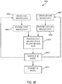
- FIG. 40 a logic flow diagram of a process 6800 of conveying a three dimensional model to a clinician is shown.
- the process 6800 can be embodied as a set of computer-executable instructions embodied as software (e.g., as stored in the memory 134) or hardware that are executed by the control circuit 132 of the control system 133 and/or the control circuit 6032.
- the visualization system 6008 executing the process 6800 can obtain, at block 6802, first imaging data from an image sensor, such as the image sensor 6035, for example.
- the first imaging data can be indicative of an outer surface contour of an anatomical structure from a first pattern of structured light detected by the image sensor 6035.
- the visualization system 6008 can obtain second imaging data from the image sensor 6035.
- the second imaging data can be indicative of a subsurface contour of the anatomical structure from a second pattern of structured light.
- the second pattern of structured light can comprise a different wavelength than the first pattern of structured light.
- the first imaging data and the second imaging data can be transmitted to the control circuit 6032, for example, at blocks 6806 and 6808, respectively.
- the control circuit 6032 can generate a three-dimensional digital representation of the anatomical structure at block 6812.
- the digital representation or model can include the outer surface contour and the subsurface contour. In various instances, additional layers of tissue can be imaged with the process 6800.
- the control circuit 6032 can transmit, at block 6814, the three-dimensional model to a display 6046, for example.
- control circuit 6032 is also configured to receive a signal from the situational awareness module 6007 of the surgical hub 6006 and, in response to the signal from the situational awareness module 6007, update the three-dimensional model of the anatomical structure.
- control circuit 6032 is further configured to obtain metadata from at least one of the first imaging data and the second imaging data at the processing block 6810.
- the control circuit 6032 can be configured to overlay the metadata with the three-dimensional model at block 6812 and transmit the additional information to the clinician at block 6814.
- the metadata can correspond to at least one of tissue velocity, tissue distortion, tissue irregularity, tissue vascularization, or identification of an embedded structure within the anatomical structure, as further described herein.
- an adaptive visualization system can provide visualization of motion at the surgical site.
- Structured light can be used with stereoscopic imaging sensors and multi-source coherent light to map light pattern distortions from one time frame to another time frame.
- the mapping of light pattern distortions across frames can be used to visualize and analyze anatomic distortion.
- any superimposed three-dimensional imaging-such as embedded structures, tissue irregularities, and/or hidden boundaries and/or tissue margins- can be proportionately deformed with the three-dimensional model.
- the visualization system can convey movement of the superimposed three-dimensional imaging to a clinician as the tissue is manipulated, e.g. dissected and/or retracted.
- an adaptive visualization system can obtain baseline visualization data based on situational awareness (e.g. input from the situational awareness module 6007).
- a baseline visualization of an anatomical structure and/or surgical site can be obtained before initiation of a surgical procedure-such as before the manipulation and dissection of tissue at the surgical site.
- the baseline visualization image of the anatomical geometry can include a visualization of the surface of the anatomical structure and its boundaries.
- Such a baseline visualization image can be used to preserve overall orientation of the surgical site and anatomic structure even as local regions within the anatomic structure are progressively disrupted, altered, or otherwise manipulated during the surgical procedure. Maintaining the baseline visualization image can allow the disrupted regions to be ignored when mapping other imaging irregularities. For example, when mapping or overlaying structures and/or features obtained by other imaging sources, the baseline visualization image can be used and the distorted regions ignored to appropriately position the additional structures and/or features in the updated visualization image.
- Situational awareness can be used to instruct and/or recommend an update to a baseline visualization image.
- the situational awareness module 6007 can instruct the control circuit 6032 to update the baseline visualization image upon identifying a particular type of surgical procedure, step in the surgical procedure, type of tissue, and/or one or more specific tissue characteristics.
- an updated baseline visualization image can be helpful after a transection or after the application of one or more rows of staples.
- distorted sub-regions within an original anatomical structure can separately create a new baseline visualization image or update an existing baseline visualization image for the distorted sub-region(s) to properly inform image overlays.
- a key region of a patient's anatomy can be updated after removal of a tumor or growth therein.
- a frame-to-frame comparison can be used to calculate the deformation of the tissue.
- surface features can be tracked and compared against subsequent frames with a reference frame set by the user or by an external data source.
- the pattern of structured light on the surface can deflect and move as the tissue surface moves.
- Stereoscopic image sensors can detect the deflection of the structured light patterns.
- a user can set the reference frame with a manual timestamp, for example.
- a ventilator i.e. external data source
- the ventilator timestamp can correspond to the expiratory pressure to denote an expired lung.
- Non-rigid iterative closest point algorithms can be used to compute correspondences between the frames.
- an initial image frame may be taken as a baseline image and subsequent image frames may be geometrically transformed so that the subsequent images are referenced to the baseline image. From this comparison, deformation between the frames can be computed. Such a technique can become more robust with increased strain rates, for example.
- the model can be analyzed to compute estimated changes in deformation for a proposed resection. For example, before a clinician resects a portion of tissue, the proposed resection line(s) can be added to the digital model, which can be updated to show the anatomical structure with the hypothetical resection.
- a clinician may intend to remove a wedge-shaped portion from the tissue at the surgical site 2325 to remove the tumor 2332 along with the tissue abnormalities 2338.
- the model can be updated to show the organ with the wedge-shaped portion removed therefrom.
- the updated model can depict the deformation of the tissue, as well as the computed stress and/or strain in the tissue based on the known tissue mechanical properties and the deformation induced by the surgery.
- the tissue can be shaded or otherwise layered with the stress and/or strain data so that the clinician is informed regarding how a particular resection may impact strain on the tissue.
- the stress/strain data may be overlaid on the image as a set of vector lines indicating stress/strain direction and line type or color to indicate the value of the stress/strain.
- a clinician may modify the proposed resection and consider an alternative strategy to reduce and/or better distribute the stresses and strains within the tissue. For example, the angles of the resections can be modified. In certain instances, the clinician can reorient a staple line with a preferred strain direction.
- the deformation data can be used to effect resection margins.
- a resection margin can be distorted in the same distortion pattern as the tissue boundary.
- the digital model can be updated by comparing the frames and computing the deformation of the tissue. As the tissue visualized with the structured light moves, the underlying resection margins 2330a, 2330b, 2330c can also shift and/or move.
- the digital model can be updated to show the surgical site 2325 including the computed updated position of the resection margins 2330a, 2330b, 2330c, which can be modeled with the same distortion pattern as the visible tissue at the surgical site 2325. It can be assumed the resection margins 2330a, 2330b, 2330c deform along with the visible tissue, for example. Additionally, with the use of tissue penetrating laser light, the structure or orientation of the underlying tissue components, such as collagen or elastin fibers, may be determined. Such fiber orientation may provide additional information regarding the stress and/or strain applied to the tissue.
- the projected distorted resection margins i.e. distortions based on frame-to-frame comparisons of structured light patterns on a tissue surface
- the newly-identified tissue characteristics can be indicated to the user in real-time during tissue dissections and/or as the clinician approaches the margin boundaries.
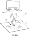
- a surgical site 6325 includes tissue T and a surgical device includes a structured light source 6350 and image sensor 6344, similar to the surgical device in FIG. 24 .
- a first refractivity R can be expected ( FIG. 25A ); however, the actual deflected reflected light R' ( FIG.
- the different refractivity can be indicative of different tissue characteristics. For example, upon complete removal of a tumor 2332 and/or tissue abnormalities 2338, the refractivity can indicate different, i.e. healthy, tissue properties. In various instances, refractivity within a boundary 6330 of an irregularity can be different than the refractivity outside the boundary 6330 of the irregularity.
- a surgical system can be configured to communicate a locally displayed coordinate system from an imaging system to a surgical instrument or other medical device to enable the instrument/device controls to be adapted to control motion relative to a local visualization coordinate system.
- at least one measurement derived from the imaging system can be utilized to define the local coordinate system.
- the surgical instrument or other medical device can be provided a transfer function from the visualization system 2108 and/or the surgical hub 2106 (e.g., as described in connection with FIGS. 17-19 ) coupled to the visualization system 2108 to enable the surgical instrument or other medical device to orient the user controls relative to the local coordinate system, rather than a standard global coordinate system or another coordinate system.
- handheld surgical instruments that have a rotatable shaft and/or an articulatable end effector require the user to understand how the shaft and the end effector are oriented relative to the patient when deciding which articulation control (e.g., left or right articulation controls) will articulate the end effector in the desired direction with respect to the patient.
- the surgical instrument or a control system coupled to the surgical instrument can be configured to automatically reorient the function of the articulation controls based on the shaft and the end effector's position relative to the handle.
- linking the reorientation of the controls directly to a change in the orientation of the surgical instrument handle assembly or rotation of the surgical instrument shaft can be undesirable in certain instances because the particular orientation of the handle assembly, shaft, and/or other surgical instrument components relative to the user may not necessarily correspond to how those components are oriented on a display screen in a video-assisted surgical procedure, such as a VATS procedure.
- Surgeons utilize display screens or video monitors as their sole POV for controlling the surgical instrument(s) during a video-assisted surgical procedure. Causing the surgical instrument controls to automatically change in response to reorientation or rotation of the surgical instrument could cause the functions of the controls to change unpredictably for users and would not necessarily correspond to the POV provided on the display for the surgeon.
- the orientation of the surgical instrument i.e., the shaft and/or end effector of the surgical instrument
- the displayed orientation of the surgical instrument relative to the global coordinate system could be utilized to adjust the function of the controls on the surgical instrument, which would in turn cause the controls to correspond to the orientation displayed on the display screen.
- the surgical instrument's controls be automatically adjusted so that they correspond to how the surgical instrument is shown on the display screen would improve the ease of using the surgical instruments and reduce user confusion and disorientation by obviating the need for surgeons to be constantly aware of how the handle, shaft, and/or end effector of the surgical instrument is oriented relative to the patient before controlling the articulation or movement of the surgical instrument.
- the orientation of the display screens could likewise be controlled in the same manner as the controls of the surgical instrument.
- the functions of the controls such as the left/right articulation controls and/or display screen of a surgical instrument, could be adjusted according to, or to coincide with, the locally displayed coordinate system.
- the present disclosure is directed to a control system for a surgical instrument that includes a user control.
- the control system can include an imaging system and a control circuit connected to the imaging system and connectable to the surgical instrument (e.g., via wired or wireless connections).
- the imaging system can be configured to visualize a surgical site, as described above.
- the control circuit can be configured to generate an image of the surgical site utilizing the imaging system, define a first coordinate system with respect to the surgical site according to the image thereof, receive a second coordinate system defined by the surgical instrument, determine a transfer function to translate a coordinate in the second coordinate system to the first coordinate system, and provide the transfer function to the surgical instrument to cause the surgical instrument to adjust the user control according to the transfer function.
- the present disclosure is directed to a surgical instrument operably in signal communication with the control system, including the imaging system that is configured to generate an image of the surgical site based on the electromagnetic radiation (EMR) reflected therefrom and define a first coordinate system with respect to the surgical site according to the image thereof.
- the surgical instrument can include a user control configured to control a function of the surgical instrument and/or a display screen.
- the surgical instrument can further include a control circuit coupled to the user control and/or the display screen.
- the control circuit can be configured to determine a second coordinate system with respect to the surgical instrument that can be provided to the control system, receive the transfer function to translate a coordinate in the second coordinate system to the first coordinate system from the control system, and adjust the user control and/or the display screen according to the transfer function.
- a VATS procedure is a surgical procedure whereby one or more surgical instruments and one or more thoracoscopes (i.e., cameras) are inserted into the patient's chest cavity through slits positioned between the patient's ribs. The cameras are utilized to provide the surgeons with a view of the interior of the patient's chest cavity to allow the surgeon to properly position/move the surgical instrument(s) and manipulate tissue/structures within the chest cavity.
- thoracoscopes i.e., cameras
- the spatial relationship between the surgical instrument and the POV displayed by the imaging system can be potentially disorienting, especially for imaging systems that allow users to pan, manipulate, and reorient the displayed visualization, as described below under the headings "Fusion of Images from Different Sources to Expand Visualization Field Scope" and "Fusion of Overlapping Images to Expand Visualization Field Scope", for example.
- the present disclosure is directed to surgical instruments and control systems associated therewith that are configured to intelligently adapt the surgical instrument controls so that they correspond to the POV displayed to the surgeon.
- FIGS. 26 and 27 are diagrams of aspects of a VATS procedure.
- the surgeon is seeking to remove a tumor 6506 located within the apical segment of the superior lobe of a lung 6508.
- the surgeon has placed a port 6502 between the second rib 6501 and the third rib 6503 to provide an access path 6504 for a surgical instrument 6510 (e.g., a surgical stapler) insertable through the port 6502 to access the tumor 6506 and/or the surrounding area within the chest cavity.
- a surgical instrument 6510 e.g., a surgical stapler
- the surgeon can place one or more cameras 6520a, 6520b through other ports 6502 that are positioned to allow the camera(s) 6520a, 6520b to visualize the interior of the patent chest cavity in the vicinity of the surgical site. Visualizing the surgical site in this manner allows the surgeon to position and orient an end effector 6514 of the surgical instrument 6510 to manipulate the tissue as needed (e.g., excise a portion of the lung 6508 around the tumor 6506).
- two cameras 6520a, 6520b are utilized, although a different number of cameras can be utilized and/or one or more of the cameras 6520a, 6520b can be oriented in a different manner depending upon the particular type of surgical procedure that is being performed and/or the region within the body of the patient 6500 that needs to be visualized.
- a variety of different coordinate systems can be defined with respect to the differing POVs of the patient, devices, or device components.
- “virtual" POVs can be defined that correspond to the virtual or predicted visualization being displayed to the surgeon and coordinate systems can also be defined according to these POVs. The generation and control of such visualizations are further described herein.
- the coordinate systems can be defined based upon sensor measurements and/or measurements by the imaging system 142 ( FIG. 2 ).
- a coordinate system with respect to a surgical instrument handle assembly 6512, a shaft 6513, or the end effector 6514 could be defined according to measurements by an accelerometer or another such sensor associated with the respective components.
- any of the aforementioned coordinate systems could be defined based upon measurements of the relative distances and/or positions of objects with respect to each other or a global coordinate system as determined by imaging the objects via the imaging system 142.
- FIG. 29 a logic flow diagram of a process 6550 of adjusting a display screen 6516 and/or user control 6518 (e.g., articulation control 6519a, 6519b) of a surgical instrument 6510 according to a displayed coordinate system is shown.
- the process 6550 can be embodied as a set of computer-executable instructions embodied as software (e.g., as stored in the memory 134) or hardware that are executed by the control circuit 132 of the control system 133.
- the control circuit 132 executing the process 6550 can generate, at block 6552, an image of the surgical site utilizing the imaging system 142.
- the imaging system 142 can be configured to generate images (including of both visible and nonvisible structures) and take measurements of or characterize imaged objects by emitting structured or non-structured EMR, emitting EMR in both the visible and nonvisible spectrums, and so on.
- the generated image can include an image directly captured by an image sensor 135 representing the POV of one of the cameras 6520a, 6520b, as shown in FIG. 30 , for example.
- the generated image can include a virtual image, as are shown in FIGS. 33 and 34 , for example.
- the control circuit 132 can define, at block 6554, a local or POV coordinate system based on the imaging system 142 for the generated image.
- the local coordinate system can be defined based on sensor measurements, imaging system measurements, tracking movement relative to an established coordinate system (e.g., a camera coordinate system x c , y c , z c as shown in FIG. 32 ), and so on.
- the control circuit 132 can receive, at block 6556, a coordinate system from the surgical instrument 6510.
- the control circuit 132 is operably in signal communication with the surgical instrument 6510 via a wireless connection (e.g., a Bluetooth connection), for example.
- the control circuit 132 can be embodied as a control circuit of a surgical hub 2106, 2236 ( FIGS. 17-19 ) and the surgical instrument 6510 can be paired with the surgical hub 2106, 2236 to transmit data therebetween.
- the control circuit 132 can determine, at block 6558, a transfer function to translate a coordinate in one of the surgical instrument coordinate system or the local coordinate system to the other coordinate system.
- the transfer function can be configured to translate.
- the transfer function can be embodied as an algorithm, an equation, a lookup table, and so on.
- the control circuit 132 can provide, at block 6560, the transfer function to the surgical instrument 6510.
- the control circuit 132 can be communicatively coupled to the surgical instrument 6510 via a wireless connection, for example, for transferring data therebetween.
- the surgical instrument 6510 can utilize the transfer function to translate the coordinates in its coordinate system to the displayed coordinate system and determine whether to adjust its controls 6518 and/or display screen 6516 based upon the updated coordinates, which indicate how the surgical instrument 6510 or components thereof are being visualized by the surgeon.
- the surgical instrument 6510 has utilized the provided transfer function to determine that the controls 6518 and display screen 6516 should be adjusted based on the updated coordinates.
- situational awareness can inform when the controls 6518 and/or the display screen 6516 are updated.
- the display screen 6516 can display a GUI 6517 that is adjusted from a first orientation, shown on the left side of FIG. 28 , to a second orientation, shown on the right side of FIG. 28 , to ensure that the GUI 6517 is oriented properly for the surgeon controlling the surgical instrument 6510.
- the GUI 6517 can further include a GUI element 6524 (e.g., an icon) indicating the POV or coordinate system being utilized by the surgical instrument 6510.
- the GUI element 6524 shifts to indicate that the POV displayed by the visualization system 2108 has changed from the device coordinate system ("DVC") to the local coordinate system ("Local”) associated with the image/video displayed by the visualization system 2108.
- DVC device coordinate system
- Local local coordinate system
- the surgical instrument controls 6518 adjusted according to the updated coordinates can include articulation controls.
- the articulation controls can include a first control 6519a configured to cause the surgical instrument 6510 to articulate in a first direction and a second control 6519b configured to cause the surgical instrument 6510 to articulate in a second direction, for example.
- the articulation controls 6519a, 6519b can be embodied as a rocker, toggle, or separate actuators and/or buttons, for example.
- the surgical instrument 6510 has caused the first articulation control 6519a and the second articulation control 6519b to swap functions in response to the change in orientation of the surgical instrument 6510.
- actuating the first articulation control 6519a would instead cause the surgical instrument 6510 to articulate in the second direction
- actuating the second articulation control 6519b would cause the surgical instrument 6510 to articulate in the first direction
- the functions of the articulation controls 6519a, 6519b can be set according to the orientation of the surgical instrument 6510 or a component thereof (e.g., the end effector 6514) as displayed to the user, such as shown in FIGS. 30 and 32-34 .
- the GUI 6517 on the display screen 6516 can be adjusted.
- the GUI 6517 can be inverted when the handle assembly 6512 is inverted.
- the GUI 6517 can include a touch screen such that the surgeon can switch between coordinate systems by interacting with the GUI 6517.
- the surgeon can toggle between a device POV, local POV, and/or one or more other POVs by interacting with the GUI 6517.
- a surgical system comprising an imaging system can be configured to create 3D representations of objects within the visualization field of the imaging system and characterize the 3D shapes to allow users to alter the displayed visualization with respect to the established coordinate system to better visualize the surgical site.
- the 3D representations can be generated from images generated from real-time sources (e.g., the imaging system 142) or non-real-time sources (e.g., CT scans or MRIs).
- the imaging system 142 can be configured to project structured light, or structured EMR, to create structured 3D shapes that can be tracked in real time. These 3D shapes could be generated in such a manner as to allow the POV displayed by the imaging system 142 to be moved or rotated away from the scanning source's local coordinate system to improve the perspective view of the user through the display.
- the present disclosure is directed to a control system, including an imaging system, a display screen, and a control circuit coupled to the imaging system and the display screen.
- the imaging system can be configured to image tissues, structures, and objects at the surgical site using a variety of different imaging techniques, including structured EMR.
- control circuit can be configured to generate a first image of the surgical site based on the structured EMR reflected therefrom received by the image sensor, receive a second image of the surgical site, generate a 3D representation of the surgical site based on the first image and the second image as aligned, display the 3D representation on the display screen, receive a user selection to manipulate the 3D representation, and update the 3D representation as displayed on the display screen from a first state to a second state according to the user selection.
- FIG. 30 illustrates a FOV 6570 of a camera 6520 ( FIG. 32 ) during a VATS procedure.
- the target of this particular illustrative procedure is a tumor 6506 located within the apical segment of the superior lobe 6580 of a lung 6508.
- a number of biological structures are identifiable within this FOV 6570, including the thoracic wall 6509, veins 6574, arteries 6576, bronchi 6578, the fissure 6582 delineating the superior lobe 6580, a pulmonary artery 6584, and a pulmonary vein 6586.
- Non-biological objects are also viewable within the FOV 6570, including the end effector 6514 and the shaft 6513 of the surgical instrument 6510 being controlled by the surgeon.
- a conventional imaging system such a view, in combination with any corresponding views from any additional camera(s) 6520 being utilized, would be the sole view(s) available to surgeons performing a video-assisted procedure.
- the cameras are placed with the intent to provide the surgeon with an adequate visualization field scope for performing the surgical procedure, the visualization field scope provided by the camera(s) 6520 may ultimately not provide the ideal FOV 6570 for performing each step or task in the surgical procedure, or unexpected obstructions may be present at the surgical site that impede the surgeon's view. Further, intraoperatively repositioning or reorienting the camera(s) 6520 can be impractical or undesirable in certain instances due to the surgical constraints of the procedure.
- a surgical system can be configured to expand the visualization field scope provided by the camera(s) 6520 by combining multiple images of the surgical site, including preoperative images and intraoperative images, to generate 3D representations of the surgical site or tissues and/or structures located at the surgical site.
- the user can then manipulate the 3D representations displayed by the imaging system 142 to visualize the surgical site from orientations that are outside the scope of the FOV 6570 of the camera(s) 6520 being utilized in the procedure.
- Such reoriented views can be referred to as "virtual POVs," as noted above.
- the surgical system can supplement the FOV 6570 provided by the camera(s) 6520 and allow surgeons to dynamically adjust the displayed visualization of the surgical site during the surgical procedure to find ideal viewing POVs for performing one or more of the surgical tasks.
- FIG. 31 is a diagram of image sources from which a 3D representation of a surgical site can be generated.
- the patient cavity would need to be viewed from multiple reference points (e.g., camera positions). These different reference points or perspectives can in turn be utilized to construct the 3D representations that can be intraoperatively manipulated by the surgeon to extend the visualization field scope beyond the fixed perspectives of the camera(s) 6520.
- at least some of the images can be captured utilizing structured EMR to map the surface of the tissues and/or structures located at the surgical site for generating the 3D representations.
- intraoperative images 6600 can be utilized in constructing the 3D representations.
- the user may be prompted by the surgical system to pan the camera 6520 around the patient cavity to observe all of the anatomy and thereby establish a baseline set of images that can be fused together to form a 3D representation of the surgical site.
- This baseline can be updated automatically throughout the procedure as tissues are manipulated, the patient is moved, and so on.
- the baseline can be generated automatically as the camera 6520 is panned and/or reoriented during the surgical procedure and updated as more regions of the patient anatomy are exposed to the FOV 6570 of the camera 6520.
- situational awareness can provide update instructions and/or suggestions to the surgeon based on the detected surgical scenario.
- preoperative images such as CT scans 6602 and MRIs 6604 can be utilized in constructing the 3D representations.
- images from non-real-time sources e.g., CT scans 6602 and MRIs 6604 can be incorporated into the real-time mapping of the surgical site in its baseline coordinate system.
- the corresponding fused images provided by the non-real-time image sources can then be utilized to generate the 3D representation and manipulated in a similar fashion as described above.
- the 3D representations can be generated from any combination of preoperative and intraoperative image sources.
- the 3D representations can be generated by aligning two-dimensional images and then constructing the 3D representation using photogrammetry techniques and/or 3D scanning software.
- some captured images can include or indicate a 3D topography of the tissues and/or structures that can aid in constructing the 3D representations, such as images captured via structured EMR. Further details regarding the generation of 3D representations of tissues and/or structures can be found in U.S. Patent Application No. 16/128,195 , titled INTEGRATION OF IMAGING DATA, filed on September 11, 2018, which is hereby incorporated by reference herein in its entirety.
- the imaging system 142 can display the 3D representations generated from the fused images and provide users with controls (e.g., a GUI) for manipulating the displayed visualization POV.
- FIG. 32 is a visualization display 6620 and GUI 6622 of the surgical procedure of FIG. 27 provided by an imaging system 142.
- the visualization display 6620 and GUI 6622 can be displayed on a display 146 ( FIG. 2 ), for example.
- the visualization display 6620 can include a real-time video feed from the camera(s) 6520 supplemented with the generated 3D representation of the surgical site, for example.
- the video feed provided by the camera(s) 6520 can be overlaid on or otherwise displayed in conjunction with the generated 3D representations on the visualization display 6620.
- the visualization display 6620 can be configured to display the video feed and transition to the 3D representations when the user causes the visualization display 6620 to display a POV that differs from the real-time video feed POV provided by the camera(s) 6520.
- the visualization display 6620 displays 3D representations of a lung 6508, a tumor 6506, and various structures 6610 (e.g., vessels).
- the 3D representations can be generated from non-real-time image sources and real-time images 6600 captured via the camera 6520, for example.
- the 3D representations can include portions that lie at least partially outside of the FOV of the camera 6520 and that can be displayed on the visualization display 6620 when desired by the user, as shown in FIG. 32 .
- the display 146 can include an interactive control, such as a GUI 6622, which allows the user to select portions of the visualization display 6620, particular camera POVs, or underlying 3D structures and then highlight, zoom in or out, rotate, or otherwise manipulate the visualization display 6620 to visualize the surgical site from a different perspective or approach than the view provided by the camera(s) 6520.
- the GUI 6622 can be configured to allow the user to select a surface, point, coordinate system, instrument, or superimposed scanned image and then adjust the visualization display 6620 with respect to that selection resulting in a view or visualization that is not directly aligned with the real-time image/video being provided by the camera(s) 6520 coupled to the imaging system 142.
- FIG. 33 illustrates the visualization display 6620 as shifted by a user to a first updated perspective 6530 corresponding to a first virtual POV x L1 , y L1, z L1 to view 3D representations of the lung 6508, the tumor 6506, and/or the end effector 6514 of the surgical instrument 6510 from a different, "local" perspective that may be more beneficial for the particular surgical procedure step.
- the first virtual POV x L1 , y L1 , z L1 is shifted relative to the camera POV x c , y c , z c (e.g., as shown in FIG.
- FIG. 34 illustrates the visualization display 6620 as shifted by a user to a second updated perspective 6632 corresponding to a second virtual POV x L2 , y L2 , z L2 to view the lung 6508, the tumor 6506, and/or the end effector 6514 of the surgical instrument 6510 from yet a different "local" perspective that is likewise shifted relative to the camera POV x c , y c , z c (e.g., as shown in FIG. 30 ).
- the GUI 6622 can include a perspective control widget 6628 that can be actuated by the user to shift, pan, or otherwise manipulate the perspective being shown on the visualization display 6620. Further, the GUI 6622 can include a coordinate GUI element 6626 that can indicate the shift in the displayed perspective relative to a reference perspective (e.g., the camera POV x c , y c , z c ). The GUI 6622 can also include various other controls for controlling the visualization display 6620, such as a zoom widget 6625 configured to cause the visualization display 6620 to zoom in our out on a particular point, structure, or object within the visualization display 6620.
- a zoom widget 6625 configured to cause the visualization display 6620 to zoom in our out on a particular point, structure, or object within the visualization display 6620.
- the imaging system 142 can be configured to display the 3D representation in a different color than the real-time video feed, highlight the structure of the 3D representation, or otherwise indicate that the user is no longer viewing the real-time video feed when the user shifts the displayed POV of the visualization display 6620 away from the real-time video feed POV provided by the camera(s) 6520. Further, the imaging system 142 can be configured to allow users to shift back to the real-time video feed POV provided by the camera(s) 6520.
- the GUI 6622 includes a POV selection widget 6624 that allows the user to shift between various POVs, including camera POVs ("CAMERA”), device POVs ("DEVICE 1” and “DEVICE 2”), and virtual POVs defined by the user ("LOCAL").
- CAMERA camera POVs
- DEVICE 1 device POVs
- DEVICE 2 virtual POVs defined by the user
- LOCAL virtual POVs defined by the user
- the visualization display 6620 can be further configured to calculate and/or display various measurements or parameters associated with the displayed tissues, structures, and objects.
- the surgical system can be configured to determine and display a tumor margin 6572 about the tumor 6506.
- the tumor margin 6572 can define the minimum volume of tissue that should be excised by the surgeon to ensure complete removal of the tumor 6506.
- the tumor margin 6572 can be calculated as a set distance extending about the tumor 6506 in three dimensions or can vary according to the size, geometry, location, and other such factors associated with the tumor 6506.
- the surgical system can be configured to determine and display relative distances between tissues, structures, and objects within the visualization display 6620.
- the visualization display 6620 includes the distance d 1 between the surgical instrument 6510 and the tumor margin 6572 and the distance d 2 between the surgical instrument 6510 and the surface of the tissue over which the surgical instrument end effector 6514 is located (which, in the illustrated example, is a lung 6508).
- the GUI 6622 can include a distance GUI element 6627 indicating the calculated distances between the various tissues, structures, and/or objects being visualized, i.e. between the corresponding elements in column A and column B.
- the aforementioned measurements are provided for illustrative purposes and the surgical system can calculate and display a variety of other measurements or parameters.
- FIG. 35 a logic flow diagram of a process 6650 of controlling a visualization display 6620 is shown.
- the process 6650 can be embodied as a set of computer-executable instructions embodied as software (e.g., as stored in the memory 134) or hardware that are executed by the control circuit 132 of the control system 133.
- FIGS. 30-34 In the following description of the process, reference should also be made to FIGS. 30-34 .
- the control circuit 132 executing the process 6650 can generate, at block 6652, a first image of the surgical site.
- the first image can be generated via the imaging system 142 utilizing structured or non-structured EMR to generate a 3D surface map of the imaged region, multispectral imaging techniques to identify and characterize nonvisible tissues and/or structures, and any other visualization techniques described above. Further, the first image can be generated as a series of images obtained by panning a camera about a surgical site to generate a 3D representation of the surgical site, as shown in FIG. 31 , for example.
- the control circuit 132 can receive, at block 6654, a second image of the surgical site.
- the second image can be a non-real-time image, such as a CT scan 6602 or MRI 6604, as shown in FIG. 31 , for example.
- the control circuit 132 can generate, at block 6656, a 3D representation of the surgical site from the first image, the second image, and any other images obtained from various image sources and then display, at block 6658, the 3D representation on a display screen coupled to the imaging system, such as an imaging system display 146 ( FIG. 2 ), a primary display 2119 ( FIG. 18 ), a non-sterile display 2109 ( FIG. 18 ), a hub display 2215 ( FIG. 19 ), a device/instrument display 2237 ( FIG. 19 ), and so on.
- the imaging system display 146 FIG. 2
- a primary display 2119 FIG. 18
- a non-sterile display 2109 FIG. 18
- a hub display 2215 FIG. 19
- a device/instrument display 2237 FIG. 19
- the control circuit 132 can update, at block 6660, the POV or state of the 3D representation according to a user selection.
- the user could update the visualization display 6620 from the camera POV shown in FIG. 30 to a first virtual POV shown in FIG. 33 or a second virtual POV shown in FIG. 34 .
- the user can provide the input to update the visualization display 6620 via a perspective control widget 6628 provided via a GUI 6622 associated with the visualization display 6620, for example.
- the surgical system can create a virtual display visualization POV that can be moved relative to the surgical site, allowing the user to see around structures, tissues, or objects (e.g., surgical instruments) at the surgical site that may be obstructing one of the imaging devices.
- a virtual display visualization POV that can be moved relative to the surgical site, allowing the user to see around structures, tissues, or objects (e.g., surgical instruments) at the surgical site that may be obstructing one of the imaging devices.
- the present disclosure is directed to a control system, including an imaging system, a display screen, and a control circuit coupled to the imaging system and the display screen.
- the imaging system can include a first image sensor having a first FOV and a second image sensor having a second FOV that at least partially overlaps with the first FOV.
- the imaging system can be configured to image tissues, structures, and objects at the surgical site using a variety of different imaging techniques, including structured EMR.
- the control circuit can be configured to generate a first image of the surgical site based on the first image sensor, generate a second image of the surgical site based on the second image sensor, align the first image and the second image according to overlapping portions thereof, generate a 3D representation of a structure based on the first image and the second image as aligned, cause the display screen to display the 3D representation, and cause the display screen to adjust a displayed portion of the 3D representation according to a user selection.
- a computational image generator could also be used to select clear image frames between the imaging devices and to display only the clear image frames in the areas where the FOVs of the imaging devices overlap.
- the surgical system can be configured to remove obstructions from the visualization display or render the obstructions semi-transparent in the areas where the FOVs of the imaging devices overlap.
- a visualization display 6620 ( FIG. 38 ) and/or a GUI 6622 ( FIG. 38 ) associated therewith can be configured to indicate to the user when the advanced visualization features are active to make the user aware that portions of the visualization display 6620 are simulated or have been adjusted from the "real" video feed provided by the cameras 6520a, 6520b ( FIG. 38 ).
- one of the cameras 6520a, 6520b can be designated as the default or primary camera, and images generated therefrom can likewise be considered to be the default or primary images displayed via the visualization display 6620.
- the images or other sensed information e.g., multispectral tissue data
- the surgical system can be interpolated by the surgical system.
- differences between the two sets of images above a threshold can prevent calculated information from being displayed to the user (e.g., due to concerns of the accuracy of the calculated information caused by the lack of consistency between the images within the primary image set).
- situational awareness as further described herein, can determine a suitable accuracy range or tolerance based on the detected surgical scenario, for example.
- the surgical site surface information obtained by the imaging devices can be used to inform the superposition of underlying structures (e.g., a tumor) imaged via another imaging source (e.g., a CT scan).
- the superposition of the underlying structures can be adjusted to account for tissue deformation in the computational image against the data from the alternative or secondary imaging source in order to confirm the projected location of the underlying structures with respect to the imaged surface.
- FIGS. 36-38 various diagrams and a visualization display 6620 of a VATS procedure being performed utilizing two cameras 6520a, 6520b that have overlapping FOVs are shown.
- the first camera 6520a can have a first FOV 6700 and the second camera 6520b can have a second FOV 6702.
- the FOVs 6700, 6702 can further define an overlapping portion 6704 therebetween. Due to the overlapping portion 6704 of the images generated by the cameras 6520a, 6520b, the images can be aligned and then utilized to generate a 3D representation of the surgical site using the various techniques described above.
- the control system 133 FIG.
- control system 133 can be configured to remove an obstruction or correct an imaging artifact present within the overlapping portion 6704 of one of the generated images and replace the offending image portion with an interpolation of the corresponding unobstructed or correct portion of the other image.
- the control system 133 can dynamically update and maximize the visualization scope provided by the visualization display 6620.
- the control system 133 can be configured to remove objects laying within the FOV of one or both of visualization FOVs 6700, 6702, such as the cameras 6520a, 6520b as shown in FIG. 38 or other surgical devices present at the surgical site, from the visualization display 6620.
- FIG. 39 a logic flow diagram of a process 6750 of controlling a visualization display 6620 ( FIG. 38 ) is shown.
- the process 6750 can be embodied as a set of computer-executable instructions embodied as software (e.g., as stored in the memory 134) or hardware that are executed by the control circuit 132 of the control system 133.
- FIGS. 36-38 In the following description of the process, reference should also be made to FIGS. 36-38 .
- the control circuit 132 executing the process 6750 can generate, at block 6752, a first image of the surgical site and can generate, at block 6754, a second image of the surgical site.
- the images can be generated via the imaging system 142 utilizing structured or non-structured EMR to generate a 3D surface map of the imaged region, multispectral imaging techniques to identify and characterize nonvisible tissues and/or structures, and any other visualization techniques described above.
- the first and second images can be generated by respective cameras 6520a, 6520b having overlapping FOVs. Therefore, the first and second images can correspondingly overlap with each other.
- the control circuit 132 can generate, at block 6756, a 3D representation of the surgical site from the first image, the second image, and any other images obtained from various image sources and then display, at block 6758, the 3D representation on a display screen coupled to the imaging system, such as an imaging system display 146 ( FIG. 2 ), a primary display 2119 ( FIG. 18 ), a non-sterile display 2109 ( FIG. 18 ), a hub display 2215 ( FIG. 19 ), a device/instrument display 2237 ( FIG. 19 ), and so on.
- the imaging system display 146 FIG. 2
- a primary display 2119 FIG. 18
- a non-sterile display 2109 FIG. 18
- a hub display 2215 FIG. 19
- a device/instrument display 2237 FIG. 19
- the control circuit 132 can update, at block 6760, the POV or state of the 3D representation according to a user selection.
- the user can provide the input to update the visualization display 6620 via a perspective control widget 6628 provided via a GUI 6622 associated with the visualization display 6620, for example.
- Various surgical visualization systems disclosed herein may be employed in one or more of the following clinical applications.
- the following clinical applications are non-exhaustive and merely illustrative applications for one or more of the various surgical visualization systems disclosed herein.
- a surgical visualization system can be employed in a number of different types of procedures for different medical specialties, such as urology, gynecology, oncology, colorectal, thoracic, bariatric / gastric, and hepato-pancreato-biliary (HPB), for example.
- urological procedures such as a prostatectomy, for example, the ureter may be detected in fat or connective tissue and/or nerves may be detected in fat, for example.
- the ureter may be detected in fat and/or in connective tissue, for example.
- a vessel may be detected in the lung or in connective tissue and/or a nerve may be detected in connective tissue (e.g., an esophagostomy).
- a vessel may be detected in fat.
- a vessel may be detected in fat (extrahepatic), in connective tissue (extrahepatic), and the bile duct may be detected in parenchyma (liver or pancreas) tissue.
- a clinician may want to remove an endometrial myoma. From a preoperative magnetic resonance imaging (MRI) scan, the clinician may know that the endometrial myoma is located on the surface of the bowel. Therefore, the clinician may want to know, intraoperatively, what tissue constitute a portion of the bowel and what tissue constitutes a portion of the rectum.
- a surgical visualization system can indicate the different types of tissue (bowel versus rectum) and convey that information to a clinician via an imaging system.
- the imaging system can determine and communicate the proximity of a surgical device to the select tissue. In such instances, the surgical visualization system can provide increased procedural efficiency without critical complications.
- a clinician may stay away from certain anatomic regions to avoid getting too close to critical structures and, thus, the clinician may not remove all of the endometriosis, for example.
- a surgical visualization system can enable the gynecologist to mitigate the risk of getting too close to the critical structure such that the gynecologist can get close enough with the surgical device to remove all the endometriosis, which can improve the patient outcomes (democratizing surgery).
- Such a system can enable the surgeon to "keep moving" during the surgical procedure instead of repeatedly stopping and restarting in order to identify areas to avoid, especially during the application of therapeutic energy such as ultrasonic or electrosurgical energy, for example.
- therapeutic energy such as ultrasonic or electrosurgical energy
- a clinician may risk dissection of a vessel at a location that is too proximal and, thus, which can affect blood supply to a lobe other than the target lobe.
- anatomic differences from patient to patient may lead to dissection of a vessel (e.g. a branch) that affects a different lobe based on the particular patient.
- a surgical visualization system can enable the identification of the correct vessel at the desired location, which enables the clinician to dissect with appropriate anatomic certainty. For example, the system can confirm that the correct vessel is in the correct place and then the clinician can safely divide the vessel.
- a clinician may make multiple dissections before dissecting at the best location due to uncertainty about the anatomy of the vessel.
- a surgical visualization system can minimize the number of dissections by indicating the correct vessel and the best location for dissection.
- Ureters and cardinal ligaments are dense and provide unique challenges during dissection. In such instances, it can be especially desirable to minimize the number of dissections.
- a clinician e.g. a surgical oncologist
- a surgical visualization system can determine and/or convey such information to the clinician intraoperatively to enhance intraoperative decision making and improve surgical outcomes.
- the surgical visualization system can be compatible with minimally invasive surgery (MIS), open surgery, and/or robotic approaches using either an endoscope or exoscope, for example.
- MIS minimally invasive surgery
- a clinician may want to turn off one or more alerts regarding the proximity of a surgical tool to one or more critical structure to avoid being overly conservative during a surgical procedure.
- the clinician may want to receive certain types of alerts, such as haptic feedback (e.g. vibrations/buzzing) to indicate proximity and/or or "no fly zones" to stay sufficiently far away from one or more critical structures.
- haptic feedback e.g. vibrations/buzzing
- a surgical visualization system can provide flexibility based on the experience of the clinician and/or desired aggressiveness of the procedure, for example. In such instances, the system provides a balance between "knowing too much” and "knowing enough" to anticipate and avoid critical structures.
- the surgical visualization system can assist in planning the next step(s) during a surgical procedure.
- a machine-readable medium may include any mechanism for storing or transmitting information in a form readable by a machine (e.g., a computer), but is not limited to, floppy diskettes, optical disks, compact disc, read-only memory (CD-ROMs), and magneto-optical disks, read-only memory (ROMs), random access memory (RAM), erasable programmable read-only memory (EPROM), electrically erasable programmable read-only memory (EEPROM), magnetic or optical cards, flash memory, or a tangible, machine-readable storage used in the transmission of information over the Internet via electrical, optical, acoustical or other forms of propagated signals (e.g., carrier waves, infrared signals, digital signals, etc.). Accordingly, the non-
- control circuit may refer to, for example, hardwired circuitry, programmable circuitry (e.g., a computer processor including one or more individual instruction processing cores, processing unit, processor, microcontroller, microcontroller unit, controller, digital signal processor (DSP), programmable logic device (PLD), programmable logic array (PLA), or field programmable gate array (FPGA)), state machine circuitry, firmware that stores instructions executed by programmable circuitry, and any combination thereof.
- programmable circuitry e.g., a computer processor including one or more individual instruction processing cores, processing unit, processor, microcontroller, microcontroller unit, controller, digital signal processor (DSP), programmable logic device (PLD), programmable logic array (PLA), or field programmable gate array (FPGA)
- state machine circuitry firmware that stores instructions executed by programmable circuitry, and any combination thereof.
- the control circuit may, collectively or individually, be embodied as circuitry that forms part of a larger system, for example, an integrated circuit (IC), an application-specific integrated circuit (ASIC), a system on-chip (SoC), desktop computers, laptop computers, tablet computers, servers, smart phones, etc.
- IC integrated circuit
- ASIC application-specific integrated circuit
- SoC system on-chip
- control circuit includes, but is not limited to, electrical circuitry having at least one discrete electrical circuit, electrical circuitry having at least one integrated circuit, electrical circuitry having at least one application specific integrated circuit, electrical circuitry forming a general purpose computing device configured by a computer program (e.g., a general purpose computer configured by a computer program which at least partially carries out processes and/or devices described herein, or a microprocessor configured by a computer program which at least partially carries out processes and/or devices described herein), electrical circuitry forming a memory device (e.g., forms of random access memory), and/or electrical circuitry forming a communications device (e.g., a modem, communications switch, or optical-electrical equipment).
- a computer program e.g., a general purpose computer configured by a computer program which at least partially carries out processes and/or devices described herein, or a microprocessor configured by a computer program which at least partially carries out processes and/or devices described herein
- electrical circuitry forming a memory device
- logic may refer to an app, software, firmware and/or circuitry configured to perform any of the aforementioned operations.
- Software may be embodied as a software package, code, instructions, instruction sets and/or data recorded on non-transitory computer readable storage medium.
- Firmware may be embodied as code, instructions or instruction sets and/or data that are hard-coded (e.g., nonvolatile) in memory devices.
- the terms "component,” “system,” “module” and the like can refer to a computer-related entity, either hardware, a combination of hardware and software, software, or software in execution.
- an “algorithm” refers to a self-consistent sequence of steps leading to a desired result, where a “step” refers to a manipulation of physical quantities and/or logic states which may, though need not necessarily, take the form of electrical or magnetic signals capable of being stored, transferred, combined, compared, and otherwise manipulated. It is common usage to refer to these signals as bits, values, elements, symbols, characters, terms, numbers, or the like. These and similar terms may be associated with the appropriate physical quantities and are merely convenient labels applied to these quantities and/or states.
- the communication devices may be capable of communicating with each other using a frame relay communications protocol.
- the frame relay communications protocol may comply or be compatible with a standard promulgated by Consultative Committee for International Circuit and Telephone (CCITT) and/or the American National Standards Institute (ANSI).
- the transceivers may be capable of communicating with each other using an Asynchronous Transfer Mode (ATM) communications protocol.
- ATM Asynchronous Transfer Mode
- the ATM communications protocol may comply or be compatible with an ATM standard published by the ATM Forum titled "ATM-MPLS Network Interworking 2.0" published August 2001, and/or later versions of this standard.
- ATM-MPLS Network Interworking 2.0 published August 2001
- proximal and distal are used herein with reference to a clinician manipulating the handle portion of the surgical instrument.
- proximal refers to the portion closest to the clinician and the term “distal” refers to the portion located away from the clinician.
- distal refers to the portion located away from the clinician.
- spatial terms such as “vertical”, “horizontal”, “up”, and “down” may be used herein with respect to the drawings.
- surgical instruments are used in many orientations and positions, and these terms are not intended to be limiting and/or absolute.
Landscapes
- Health & Medical Sciences (AREA)
- Life Sciences & Earth Sciences (AREA)
- Engineering & Computer Science (AREA)
- Surgery (AREA)
- Public Health (AREA)
- General Health & Medical Sciences (AREA)
- Medical Informatics (AREA)
- Nuclear Medicine, Radiotherapy & Molecular Imaging (AREA)
- Biomedical Technology (AREA)
- Heart & Thoracic Surgery (AREA)
- Veterinary Medicine (AREA)
- Animal Behavior & Ethology (AREA)
- Molecular Biology (AREA)
- Physics & Mathematics (AREA)
- Pathology (AREA)
- Radiology & Medical Imaging (AREA)
- Optics & Photonics (AREA)
- Biophysics (AREA)
- Robotics (AREA)
- Epidemiology (AREA)
- Primary Health Care (AREA)
- General Physics & Mathematics (AREA)
- Oral & Maxillofacial Surgery (AREA)
- Signal Processing (AREA)
- Theoretical Computer Science (AREA)
- Computer Vision & Pattern Recognition (AREA)
- Computing Systems (AREA)
- Geometry (AREA)
- Computer Graphics (AREA)
- Human Computer Interaction (AREA)
- Plasma & Fusion (AREA)
- Otolaryngology (AREA)
- Urology & Nephrology (AREA)
- Endoscopes (AREA)
- Apparatus For Radiation Diagnosis (AREA)
Applications Claiming Priority (1)
| Application Number | Priority Date | Filing Date | Title |
|---|---|---|---|
| US16/729,747 US12002571B2 (en) | 2019-12-30 | 2019-12-30 | Dynamic surgical visualization systems |
Publications (3)
| Publication Number | Publication Date |
|---|---|
| EP3845189A2 true EP3845189A2 (de) | 2021-07-07 |
| EP3845189A3 EP3845189A3 (de) | 2021-09-01 |
| EP3845189B1 EP3845189B1 (de) | 2024-07-24 |
Family
ID=73139078
Family Applications (1)
| Application Number | Title | Priority Date | Filing Date |
|---|---|---|---|
| EP20217602.0A Active EP3845189B1 (de) | 2019-12-30 | 2020-12-29 | Dynamisches chirurgisches visualisierungssystem |
Country Status (6)
| Country | Link |
|---|---|
| US (1) | US12002571B2 (de) |
| EP (1) | EP3845189B1 (de) |
| JP (1) | JP7707173B2 (de) |
| CN (1) | CN115135268A (de) |
| BR (1) | BR112022012946A2 (de) |
| WO (1) | WO2021136994A1 (de) |
Cited By (3)
| Publication number | Priority date | Publication date | Assignee | Title |
|---|---|---|---|---|
| WO2023052951A1 (en) * | 2021-09-29 | 2023-04-06 | Cilag Gmbh International | Surgical systems with intraluminal and extraluminal cooperative instruments |
| WO2023052955A1 (en) * | 2021-09-29 | 2023-04-06 | Cilag Gmbh International | Instrument control surgical imaging systems |
| US12478363B2 (en) | 2021-09-29 | 2025-11-25 | Cilag Gmbh International | Surgical systems with intraluminal and extraluminal cooperative instruments |
Families Citing this family (69)
| Publication number | Priority date | Publication date | Assignee | Title |
|---|---|---|---|---|
| JP2021510327A (ja) * | 2018-01-10 | 2021-04-22 | コヴィディエン リミテッド パートナーシップ | コンピュータビジョンを利用したロボット外科システムのツールの位置および状態の判定 |
| US11559298B2 (en) | 2018-07-16 | 2023-01-24 | Cilag Gmbh International | Surgical visualization of multiple targets |
| US12257013B2 (en) | 2019-03-15 | 2025-03-25 | Cilag Gmbh International | Robotic surgical systems with mechanisms for scaling camera magnification according to proximity of surgical tool to tissue |
| US11648060B2 (en) | 2019-12-30 | 2023-05-16 | Cilag Gmbh International | Surgical system for overlaying surgical instrument data onto a virtual three dimensional construct of an organ |
| US11744667B2 (en) | 2019-12-30 | 2023-09-05 | Cilag Gmbh International | Adaptive visualization by a surgical system |
| US11284963B2 (en) | 2019-12-30 | 2022-03-29 | Cilag Gmbh International | Method of using imaging devices in surgery |
| US11832996B2 (en) | 2019-12-30 | 2023-12-05 | Cilag Gmbh International | Analyzing surgical trends by a surgical system |
| US11219501B2 (en) | 2019-12-30 | 2022-01-11 | Cilag Gmbh International | Visualization systems using structured light |
| US12453592B2 (en) | 2019-12-30 | 2025-10-28 | Cilag Gmbh International | Adaptive surgical system control according to surgical smoke cloud characteristics |
| US11776144B2 (en) | 2019-12-30 | 2023-10-03 | Cilag Gmbh International | System and method for determining, adjusting, and managing resection margin about a subject tissue |
| US11896442B2 (en) | 2019-12-30 | 2024-02-13 | Cilag Gmbh International | Surgical systems for proposing and corroborating organ portion removals |
| US11759283B2 (en) | 2019-12-30 | 2023-09-19 | Cilag Gmbh International | Surgical systems for generating three dimensional constructs of anatomical organs and coupling identified anatomical structures thereto |
| US12207881B2 (en) | 2019-12-30 | 2025-01-28 | Cilag Gmbh International | Surgical systems correlating visualization data and powered surgical instrument data |
| US12053223B2 (en) | 2019-12-30 | 2024-08-06 | Cilag Gmbh International | Adaptive surgical system control according to surgical smoke particulate characteristics |
| WO2021180333A1 (en) * | 2020-03-13 | 2021-09-16 | Brainlab Ag | Stability estimation of a point set registration |
| US12201266B2 (en) | 2020-04-23 | 2025-01-21 | Johnson & Johnson Surgical Vision, Inc. | Location pad surrounding at least part of patient eye and having optical tracking elements |
| DE112021004183T5 (de) * | 2020-08-05 | 2023-06-29 | Gyrus Acmi, Inc. D/B/A Olympus Surgical Technologies America | Tiefen- und konturerfassung für anatomische ziele |
| US12204106B2 (en) * | 2020-08-20 | 2025-01-21 | Johnson & Johnson Surgical Vision, Inc. | Presenting visual and thermal images in a headset during phacoemulsification |
| DE102020124220B4 (de) * | 2020-09-17 | 2025-07-17 | Olympus Winter & Ibe Gmbh | Verfahren und System zur stereoendoskopischen Fluoreszenzmessung sowie Softwareprogrammprodukt |
| US12236624B2 (en) * | 2020-09-23 | 2025-02-25 | Smith & Nephew, Inc. | Optical caliper for 3-D endoscopic imaging and measurement |
| US12580072B2 (en) | 2020-10-02 | 2026-03-17 | Cilag Gmbh International | Cloud analytics packages |
| US11748924B2 (en) | 2020-10-02 | 2023-09-05 | Cilag Gmbh International | Tiered system display control based on capacity and user operation |
| US11992372B2 (en) | 2020-10-02 | 2024-05-28 | Cilag Gmbh International | Cooperative surgical displays |
| US12213801B2 (en) | 2020-10-02 | 2025-02-04 | Cilag Gmbh International | Surgical visualization and particle trend analysis system |
| US12484897B2 (en) | 2020-10-02 | 2025-12-02 | Cilag Gmbh International | Surgical instrument with adaptive configuration control |
| US12016566B2 (en) | 2020-10-02 | 2024-06-25 | Cilag Gmbh International | Surgical instrument with adaptive function controls |
| US11883052B2 (en) | 2020-10-02 | 2024-01-30 | Cilag Gmbh International | End effector updates |
| US11877897B2 (en) | 2020-10-02 | 2024-01-23 | Cilag Gmbh International | Situational awareness of instruments location and individualization of users to control displays |
| US11911030B2 (en) | 2020-10-02 | 2024-02-27 | Cilag Gmbh International | Communication capability of a surgical device with component |
| US12472032B2 (en) | 2020-10-02 | 2025-11-18 | Cilag Gmbh International | Monitoring of user visual gaze to control which display system displays the primary information |
| US11877792B2 (en) | 2020-10-02 | 2024-01-23 | Cilag Gmbh International | Smart energy combo control options |
| US11672534B2 (en) | 2020-10-02 | 2023-06-13 | Cilag Gmbh International | Communication capability of a smart stapler |
| US11830602B2 (en) | 2020-10-02 | 2023-11-28 | Cilag Gmbh International | Surgical hub having variable interconnectivity capabilities |
| US11963683B2 (en) | 2020-10-02 | 2024-04-23 | Cilag Gmbh International | Method for operating tiered operation modes in a surgical system |
| US12064293B2 (en) | 2020-10-02 | 2024-08-20 | Cilag Gmbh International | Field programmable surgical visualization system |
| US20220104878A1 (en) * | 2020-10-06 | 2022-04-07 | Mazor Robotics Ltd. | Method, device, and system for image generation based on calculated robotic arm positions |
| KR102412618B1 (ko) * | 2020-11-18 | 2022-06-23 | 가톨릭대학교 산학협력단 | 자궁 경부 이미지 분석 방법 및 장치 |
| US12100496B2 (en) | 2021-01-22 | 2024-09-24 | Cilag Gmbh International | Patient biomarker monitoring with outcomes to monitor overall healthcare delivery |
| US12440285B2 (en) | 2021-01-22 | 2025-10-14 | Cilag Gmbh International | Prediction of hemostasis issues based on biomarker monitoring |
| US12011163B2 (en) | 2021-01-22 | 2024-06-18 | Cilag Gmbh International | Prediction of tissue irregularities based on biomarker monitoring |
| US11682487B2 (en) | 2021-01-22 | 2023-06-20 | Cilag Gmbh International | Active recognition and pairing sensing systems |
| US12543982B2 (en) | 2021-01-22 | 2026-02-10 | Cilag Gmbh International | Method of adjusting a surgical parameter based on biomarker measurements |
| US11694533B2 (en) | 2021-01-22 | 2023-07-04 | Cilag Gmbh International | Predictive based system adjustments based on biomarker trending |
| US20230020346A1 (en) * | 2021-07-14 | 2023-01-19 | Cilag Gmbh International | Scene adaptive endoscopic hyperspectral imaging system |
| US12075984B2 (en) * | 2021-07-14 | 2024-09-03 | Cilag Gmbh International | Stereoscopic endoscope with critical structure depth estimation |
| US12053150B2 (en) * | 2021-08-11 | 2024-08-06 | Terumo Cardiovascular Systems Corporation | Endoscopic vessel harvesting with thermal management and augmented reality display |
| US12290319B2 (en) | 2021-09-29 | 2025-05-06 | Cilag Gmbh International | Methods for controlling cooperative surgical instruments |
| US12364545B2 (en) | 2021-09-29 | 2025-07-22 | Cilag Gmbh International | Surgical devices, systems, and methods using fiducial identification and tracking |
| US12137986B2 (en) | 2021-09-29 | 2024-11-12 | Cilag Gmbh International | Methods for controlling cooperative surgical instruments |
| US12295667B2 (en) | 2021-09-29 | 2025-05-13 | Cilag Gmbh International | Surgical devices, systems, and methods using multi-source imaging |
| US12376910B2 (en) * | 2021-09-29 | 2025-08-05 | Cilag Gmbh International | Methods for controlling cooperative surgical instruments |
| US12171399B2 (en) | 2021-09-29 | 2024-12-24 | Cilag Gmbh International | Surgical devices, systems, and methods using multi-source imaging |
| US12239387B2 (en) | 2021-09-29 | 2025-03-04 | Cilag Gmbh International | Surgical methods using fiducial identification and tracking |
| US20230110791A1 (en) * | 2021-09-29 | 2023-04-13 | Cilag Gmbh International | Instrument Control Imaging Systems for Visualization of Upcoming Surgical Procedure Steps |
| US12266098B2 (en) * | 2021-11-11 | 2025-04-01 | International Business Machines Corporation | Improving model performance by artificial blending of healthy tissue |
| US20250082411A1 (en) * | 2021-12-16 | 2025-03-13 | University Of Miami | Augmented and mixed reality incorporating pathology results in surgical settings |
| US20230346199A1 (en) * | 2022-04-29 | 2023-11-02 | 3Dintegrated Aps | Anatomy measurement |
| JP7531547B2 (ja) * | 2022-06-15 | 2024-08-09 | 株式会社日進Fulfil | 切削加工装置 |
| US12254977B2 (en) | 2022-12-30 | 2025-03-18 | Cilag Gmbh International | Detection of knock-off or counterfeit surgical devices |
| US12475978B2 (en) | 2022-12-30 | 2025-11-18 | Cilag GmbH Intenational | Adaptable operation range for a surgical device |
| US12315617B2 (en) | 2022-12-30 | 2025-05-27 | Cilag Gmbh International | Surgical data processing associated with multiple system hierarchy levels |
| US12573495B2 (en) | 2022-12-30 | 2026-03-10 | Cilag Gmbh International | Surgical computing system with support for interrelated machine learning models |
| US12573496B2 (en) | 2022-12-30 | 2026-03-10 | Cilag Gmbh International | Advanced data timing in a surgical computing system |
| US12562254B2 (en) | 2022-12-30 | 2026-02-24 | Cilag Gmbh International | Surgical data specialty harmonization for training machine learning models |
| US12531156B2 (en) | 2022-12-30 | 2026-01-20 | Cilag Gmbh International | Method for advanced algorithm support |
| US12496142B2 (en) * | 2023-02-02 | 2025-12-16 | Edda Technology, Inc. | System and method for automated surgical position marking in robot-assisted surgery |
| US12496149B2 (en) | 2023-02-02 | 2025-12-16 | Edda Technology, Inc. | System and method for automated simultaneous trocar and robot base location determination |
| US12245823B2 (en) | 2023-02-02 | 2025-03-11 | Edda Technology, Inc. | System and method for automated trocar and robot base location determination |
| FR3154592A1 (fr) | 2023-10-26 | 2025-05-02 | Maquet Sas | Dispositif d'émission et de détection de l’infrarouge à ondes courtes pour l’imagerie médicale |
Citations (21)
| Publication number | Priority date | Publication date | Assignee | Title |
|---|---|---|---|---|
| US9274047B2 (en) | 2013-05-24 | 2016-03-01 | Massachusetts Institute Of Technology | Methods and apparatus for imaging of occluded objects |
| US20170055819A1 (en) | 2014-02-21 | 2017-03-02 | 3Dintegrated Aps | Set comprising a surgical instrument |
| US20170251900A1 (en) | 2015-10-09 | 2017-09-07 | 3Dintegrated Aps | Depiction system |
| US20190104919A1 (en) | 2012-05-20 | 2019-04-11 | Ethicon Llc | Method for situational awareness for surgical network or surgical network connected device capable of adjusting function based on a sensed situation or usage |
| US20190208641A1 (en) | 2017-12-28 | 2019-07-04 | Ethicon Llc | Method of using reinforced flexible circuits with multiple sensors to optimize performance of radio frequency devices |
| US20190200905A1 (en) | 2017-12-28 | 2019-07-04 | Ethicon Llc | Characterization of tissue irregularities through the use of mono-chromatic light refractivity |
| US20190201594A1 (en) | 2017-12-28 | 2019-07-04 | Ethicon Llc | Method of sensing particulate from smoke evacuated from a patient, adjusting the pump speed based on the sensed information, and communicating the functional parameters of the system to the hub |
| US20190201120A1 (en) | 2017-12-28 | 2019-07-04 | Ethicon Llc | Sensing arrangements for robot-assisted surgical platforms |
| US20190201046A1 (en) | 2017-12-28 | 2019-07-04 | Ethicon Llc | Method for controlling smart energy devices |
| US20190201047A1 (en) | 2017-12-28 | 2019-07-04 | Ethicon Llc | Method for smart energy device infrastructure |
| US20190200981A1 (en) | 2017-12-28 | 2019-07-04 | Ethicon Llc | Method of compressing tissue within a stapling device and simultaneously displaying the location of the tissue within the jaws |
| US20190201137A1 (en) | 2017-12-28 | 2019-07-04 | Ethicon Llc | Method of robotic hub communication, detection, and control |
| US20190200998A1 (en) | 2017-12-28 | 2019-07-04 | Ethicon Llc | Method for circular stapler control algorithm adjustment based on situational awareness |
| US20190201136A1 (en) | 2017-12-28 | 2019-07-04 | Ethicon Llc | Method of hub communication |
| US20190206563A1 (en) | 2017-12-28 | 2019-07-04 | Ethicon Llc | Method for adaptive control schemes for surgical network control and interaction |
| US20190201111A1 (en) | 2017-12-28 | 2019-07-04 | Ethicon Llc | Drive arrangements for robot-assisted surgical platforms |
| US20190201045A1 (en) | 2017-12-28 | 2019-07-04 | Ethicon Llc | Method for smoke evacuation for surgical hub |
| US20190206569A1 (en) | 2017-12-28 | 2019-07-04 | Ethicon Llc | Method of cloud based data analytics for use with the hub |
| US20190201142A1 (en) | 2017-12-28 | 2019-07-04 | Ethicon Llc | Automatic tool adjustments for robot-assisted surgical platforms |
| US20190206562A1 (en) | 2017-12-28 | 2019-07-04 | Ethicon Llc | Method of hub communication, processing, display, and cloud analytics |
| US20190206564A1 (en) | 2017-12-28 | 2019-07-04 | Ethicon Llc | Method for facility data collection and interpretation |
Family Cites Families (474)
| Publication number | Priority date | Publication date | Assignee | Title |
|---|---|---|---|---|
| US3901602A (en) | 1974-05-13 | 1975-08-26 | Us Commerce | Light scattering method and apparatus for the chemical characterization of particulate matter |
| DE3611337A1 (de) | 1986-04-04 | 1987-10-22 | Deutsche Forsch Luft Raumfahrt | In einer kunststoffkugel untergebrachte, opto-elektronische anordnung |
| US4986262A (en) | 1987-03-31 | 1991-01-22 | Kabushiki Kaisha Toshiba | Measuring endoscope |
| US4753641A (en) | 1987-09-10 | 1988-06-28 | Vaslow Dale F | Emergency medical needle |
| EP0359681B1 (de) | 1988-09-15 | 1995-11-08 | The Board Of Trustees Of The University Of Arkansas | Kennzeichnung von Teilchen durch modulierte dynamische Lichtstreuung |
| US5460182A (en) | 1992-09-14 | 1995-10-24 | Sextant Medical Corporation | Tissue penetrating apparatus and methods |
| US5609562A (en) | 1993-11-16 | 1997-03-11 | Worldwide Optical Trocar Licensing Corporation | Visually directed trocar and method |
| WO1999040841A1 (en) | 1998-02-11 | 1999-08-19 | Non-Invasive Technology, Inc. | Imaging and characterization of brain tissue |
| MY130456A (en) | 1998-07-30 | 2007-06-29 | David Lubowski | Sigmoidoscope |
| US7137980B2 (en) | 1998-10-23 | 2006-11-21 | Sherwood Services Ag | Method and system for controlling output of RF medical generator |
| US6951535B2 (en) | 2002-01-16 | 2005-10-04 | Intuitive Surgical, Inc. | Tele-medicine system that transmits an entire state of a subsystem |
| US6503195B1 (en) * | 1999-05-24 | 2003-01-07 | University Of North Carolina At Chapel Hill | Methods and systems for real-time structured light depth extraction and endoscope using real-time structured light depth extraction |
| DE10005628B4 (de) | 2000-02-09 | 2006-04-20 | Siemens Ag | Verfahren und Vorrichtung zur Ausrichtung eines medizinischen Instruments am Körper eines Patienten unter Verwendung eines Computer-Tomographen |
| AU2001251134B2 (en) | 2000-03-31 | 2006-02-02 | Angiodynamics, Inc. | Tissue biopsy and treatment apparatus and method |
| US6614453B1 (en) | 2000-05-05 | 2003-09-02 | Koninklijke Philips Electronics, N.V. | Method and apparatus for medical image display for surgical tool planning and navigation in clinical environments |
| EP1324802B1 (de) | 2000-09-12 | 2006-11-15 | Peter K. Law | Katheter für den myogenen zelltransfer |
| US6826424B1 (en) | 2000-12-19 | 2004-11-30 | Haishan Zeng | Methods and apparatus for fluorescence and reflectance imaging and spectroscopy and for contemporaneous measurements of electromagnetic radiation with multiple measuring devices |
| US7740623B2 (en) | 2001-01-13 | 2010-06-22 | Medtronic, Inc. | Devices and methods for interstitial injection of biologic agents into tissue |
| US6632183B2 (en) | 2001-02-12 | 2003-10-14 | Thermal Technologies, Inc. | Perfusion sensitive biopsy extractor |
| US7547307B2 (en) | 2001-02-27 | 2009-06-16 | Smith & Nephew, Inc. | Computer assisted knee arthroplasty instrumentation, systems, and processes |
| EP1372516B1 (de) | 2001-02-27 | 2009-05-13 | Smith & Nephew, Inc. | Chirurgisches navigationssystem zur teilweisen kniegelenkrekonstruktion |
| US20050113846A1 (en) | 2001-02-27 | 2005-05-26 | Carson Christopher P. | Surgical navigation systems and processes for unicompartmental knee arthroplasty |
| NO20011769D0 (no) | 2001-04-06 | 2001-04-06 | Bjoern Franc Iversen | Anordning og system for gjensidig posisjonering av protesedeler |
| US8231639B2 (en) | 2001-11-28 | 2012-07-31 | Aptus Endosystems, Inc. | Systems and methods for attaching a prosthesis within a body lumen or hollow organ |
| DE10158775B4 (de) | 2001-11-30 | 2004-05-06 | 3Dconnexion Gmbh | Anordnung zum Erfassen von Relativbewegungen oder Relativpositionen zweier Objekte |
| US7747311B2 (en) | 2002-03-06 | 2010-06-29 | Mako Surgical Corp. | System and method for interactive haptic positioning of a medical device |
| US7831292B2 (en) | 2002-03-06 | 2010-11-09 | Mako Surgical Corp. | Guidance system and method for surgical procedures with improved feedback |
| US8010180B2 (en) | 2002-03-06 | 2011-08-30 | Mako Surgical Corp. | Haptic guidance system and method |
| US8996169B2 (en) | 2011-12-29 | 2015-03-31 | Mako Surgical Corp. | Neural monitor-based dynamic haptics |
| US6887247B1 (en) | 2002-04-17 | 2005-05-03 | Orthosoft Inc. | CAS drill guide and drill tracking system |
| JP4106991B2 (ja) | 2002-07-15 | 2008-06-25 | ブラザー工業株式会社 | ミシン制御装置、ミシン制御方法およびミシン制御プログラム |
| US20040176751A1 (en) | 2002-08-14 | 2004-09-09 | Endovia Medical, Inc. | Robotic medical instrument system |
| AU2003273680A1 (en) | 2002-10-04 | 2004-04-23 | Orthosoft Inc. | Computer-assisted hip replacement surgery |
| US20040082842A1 (en) | 2002-10-28 | 2004-04-29 | Lumba Vijay K. | System for monitoring fetal status |
| US20090149871A9 (en) | 2002-11-01 | 2009-06-11 | Jonathan Kagan | Devices and methods for treating morbid obesity |
| ATE476908T1 (de) | 2003-04-18 | 2010-08-15 | Medispectra Inc | System und diagnoseverfahren zur optischen detektion von verdächtigen stellen einer gewebeprobe |
| US20100081875A1 (en) | 2003-07-15 | 2010-04-01 | EndoRobotics Inc. | Surgical Device For Minimal Access Surgery |
| US7905840B2 (en) | 2003-10-17 | 2011-03-15 | Nuvasive, Inc. | Surgical access system and related methods |
| US10041822B2 (en) | 2007-10-05 | 2018-08-07 | Covidien Lp | Methods to shorten calibration times for powered devices |
| US20080269596A1 (en) | 2004-03-10 | 2008-10-30 | Ian Revie | Orthpaedic Monitoring Systems, Methods, Implants and Instruments |
| US20080228104A1 (en) | 2004-03-11 | 2008-09-18 | Uber Arthur E | Energy Assisted Medical Devices, Systems and Methods |
| DE602004006227T2 (de) | 2004-03-17 | 2008-01-03 | 3Dconnexion Gmbh | Benutzerschnittstellenvorrichtung |
| US20050279354A1 (en) | 2004-06-21 | 2005-12-22 | Harvey Deutsch | Structures and Methods for the Joint Delivery of Fluids and Light |
| US9072535B2 (en) | 2011-05-27 | 2015-07-07 | Ethicon Endo-Surgery, Inc. | Surgical stapling instruments with rotatable staple deployment arrangements |
| AU2004323338B2 (en) | 2004-09-15 | 2011-01-20 | Ao Technology Ag | Calibrating device |
| WO2006034129A2 (en) | 2004-09-17 | 2006-03-30 | Jmar Research, Inc. | Systems and methods for detecting scattered light from a particle using illumination incident at an angle |
| US20080015664A1 (en) | 2004-10-06 | 2008-01-17 | Podhajsky Ronald J | Systems and methods for thermally profiling radiofrequency electrodes |
| US20060079841A1 (en) | 2004-10-07 | 2006-04-13 | University Technologies International Inc. | Rapid insufflation drug compartment |
| US9161820B2 (en) | 2004-10-28 | 2015-10-20 | Nico Corporation | Surgical access assembly and method of using same |
| CA2883638C (en) | 2004-11-12 | 2017-06-20 | Xtralis Technologies Ltd | Particle detector, system and method |
| US7477931B2 (en) | 2004-12-06 | 2009-01-13 | Cambridge Research & Instruments, Inc. | Systems and methods for in-vivo and optical imaging and measurement |
| EP1677099A1 (de) | 2004-12-30 | 2006-07-05 | Danmarks Tekniske Universitet | Verfahren und Vorrichtung zur Oberflächenklassifizierung |
| US7564945B2 (en) | 2005-02-11 | 2009-07-21 | University Of Florida Research Foundation, Inc. | System including computed tomography device for image guided treatment |
| JP2008532602A (ja) | 2005-03-11 | 2008-08-21 | ブラッコ・イメージング・ソシエタ・ペル・アチオニ | 外科手術ナビゲーションと顕微鏡による可視化の方法と装置 |
| US20060206007A1 (en) | 2005-03-14 | 2006-09-14 | Bala John L | Disposable illuminator endoscope |
| US7842027B2 (en) | 2005-03-21 | 2010-11-30 | Lieponis Jonas V | Multi-purpose surgical instrument with integral optical system |
| US20060224045A1 (en) | 2005-03-31 | 2006-10-05 | Depuy Spine, Inc. | Integrated access device and light source for surgical procedures |
| AU2006238292B2 (en) | 2005-03-31 | 2010-04-15 | Olympus Medical Systems Corp. | Surgery assisting apparatus and treatment assisting apparatus |
| JP4766902B2 (ja) | 2005-03-31 | 2011-09-07 | オリンパスメディカルシステムズ株式会社 | 手術支援装置 |
| US9005115B2 (en) | 2005-04-04 | 2015-04-14 | Invuity, Inc. | Illuminated telescoping cannula |
| US7510524B2 (en) | 2005-04-04 | 2009-03-31 | Invuity, Inc. | Optical waveguide sheath |
| US8073528B2 (en) | 2007-09-30 | 2011-12-06 | Intuitive Surgical Operations, Inc. | Tool tracking systems, methods and computer products for image guided surgery |
| US8932208B2 (en) | 2005-05-26 | 2015-01-13 | Maquet Cardiovascular Llc | Apparatus and methods for performing minimally-invasive surgical procedures |
| US20100030231A1 (en) | 2005-06-02 | 2010-02-04 | Ian Revie | Surgical system and method |
| US20120143341A1 (en) | 2006-12-12 | 2012-06-07 | Arthrodisc, L.L.C. | Devices and methods for visual differentiation of intervertebral spaces |
| US8500756B2 (en) | 2005-06-13 | 2013-08-06 | Ethicon Endo. Surgery, Inc. | Quick load mechanism for a surgical suturing apparatus |
| US20070014784A1 (en) | 2005-06-23 | 2007-01-18 | Medtronic Vascular, Inc. | Methods and Systems for Treating Injured Cardiac Tissue |
| US20070172472A1 (en) | 2005-06-23 | 2007-07-26 | Asha Nayak | Methods and Systems for Treating Injured Cardiac Tissue |
| US20070093748A1 (en) | 2005-06-23 | 2007-04-26 | Medtronic Vascular, Inc. | Methods and systems for treating injured cardiac tissue |
| US20100280493A1 (en) | 2005-06-23 | 2010-11-04 | Asha Nayak | Methods and Systems for Treating Injured Cardiac Tissue |
| DE102005034684B4 (de) | 2005-07-25 | 2014-10-16 | Siemens Aktiengesellschaft | Computertomographisches System zur kontrollierten Durchführung eines interventionellen Eingriffs |
| US8451327B2 (en) | 2005-08-18 | 2013-05-28 | Hoya Corporation | Electronic endoscope, endoscope light unit, endoscope processor, and electronic endoscope system |
| ES2390593T3 (es) | 2005-09-13 | 2012-11-14 | The Trustees Of Columbia University In The City Of New York | Dispositivo insertable y sistema para un procedimiento de acceso mínimo |
| WO2007033326A2 (en) | 2005-09-14 | 2007-03-22 | Welch Allyn, Inc. | Medical apparatus comprising and adaptive lens |
| US20070066970A1 (en) | 2005-09-16 | 2007-03-22 | Leonard Ineson | Integrated electrosurgical cart and surgical smoke evacuator unit |
| US8079950B2 (en) | 2005-09-29 | 2011-12-20 | Intuitive Surgical Operations, Inc. | Autofocus and/or autoscaling in telesurgery |
| US20070100210A1 (en) | 2005-11-02 | 2007-05-03 | Depuy Spine, Inc. | Illuminated surgical access system including a surgical access device and coupled light emitter |
| US7874982B2 (en) | 2005-11-02 | 2011-01-25 | Depuy Spine, Inc. | Illuminated surgical access system including a surgical access device and coupled light emitter |
| US20070265495A1 (en) | 2005-12-15 | 2007-11-15 | Medivision, Inc. | Method and apparatus for field of view tracking |
| US20070175955A1 (en) | 2006-01-31 | 2007-08-02 | Shelton Frederick E Iv | Surgical cutting and fastening instrument with closure trigger locking mechanism |
| US8763879B2 (en) | 2006-01-31 | 2014-07-01 | Ethicon Endo-Surgery, Inc. | Accessing data stored in a memory of surgical instrument |
| US8161977B2 (en) | 2006-01-31 | 2012-04-24 | Ethicon Endo-Surgery, Inc. | Accessing data stored in a memory of a surgical instrument |
| US7845537B2 (en) | 2006-01-31 | 2010-12-07 | Ethicon Endo-Surgery, Inc. | Surgical instrument having recording capabilities |
| US8820603B2 (en) | 2006-01-31 | 2014-09-02 | Ethicon Endo-Surgery, Inc. | Accessing data stored in a memory of a surgical instrument |
| US7770775B2 (en) | 2006-01-31 | 2010-08-10 | Ethicon Endo-Surgery, Inc. | Motor-driven surgical cutting and fastening instrument with adaptive user feedback |
| US7766210B2 (en) | 2006-01-31 | 2010-08-03 | Ethicon Endo-Surgery, Inc. | Motor-driven surgical cutting and fastening instrument with user feedback system |
| US8623026B2 (en) | 2006-02-06 | 2014-01-07 | Conformis, Inc. | Patient selectable joint arthroplasty devices and surgical tools incorporating anatomical relief |
| US8989528B2 (en) | 2006-02-22 | 2015-03-24 | Hansen Medical, Inc. | Optical fiber grating sensors and methods of manufacture |
| EP1843243B1 (de) | 2006-04-05 | 2012-02-22 | Société Civile "GALILEO 2011" | Optoelektronische Vorrichtung zur Bestimmung der relativen Bewegungen oder relativen Positionen zweier Objekte |
| AU2007254159B2 (en) | 2006-05-19 | 2013-07-04 | Mako Surgical Corp. | System and method for verifying calibration of a surgical device |
| US8560047B2 (en) | 2006-06-16 | 2013-10-15 | Board Of Regents Of The University Of Nebraska | Method and apparatus for computer aided surgery |
| US10376314B2 (en) | 2006-07-14 | 2019-08-13 | Neuwave Medical, Inc. | Energy delivery systems and uses thereof |
| US7551800B2 (en) | 2006-08-09 | 2009-06-23 | Fotonation Vision Limited | Detection of airborne flash artifacts using preflash image |
| US20080144906A1 (en) | 2006-10-09 | 2008-06-19 | General Electric Company | System and method for video capture for fluoroscopy and navigation |
| US20140163664A1 (en) | 2006-11-21 | 2014-06-12 | David S. Goldsmith | Integrated system for the ballistic and nonballistic infixion and retrieval of implants with or without drug targeting |
| US11389171B2 (en) | 2006-11-21 | 2022-07-19 | David S. Goldsmith | Integrated system for the infixion and retrieval of implants |
| EP1925256A1 (de) | 2006-11-24 | 2008-05-28 | BrainLAB AG | Verfahren und Vorrichtung zur Registrierung einer anatomischen Struktur mit Markern |
| US20080194930A1 (en) | 2007-02-09 | 2008-08-14 | Harris Melvyn L | Infrared-visible needle |
| EP2129301A4 (de) | 2007-03-13 | 2015-03-25 | Peter S Harris | Verfahren und vorrichtungen zur verringerung des magenvolumens |
| JP4916011B2 (ja) | 2007-03-20 | 2012-04-11 | 株式会社日立製作所 | マスタ・スレーブ式マニピュレータシステム |
| WO2008122008A1 (en) | 2007-04-02 | 2008-10-09 | Stryker Corporation | Medical/surgical tool for both identifying subcutaneous target tissue by means of emitting an interrrogation signal and positioning a catheter at the target |
| US20140320684A1 (en) | 2007-04-03 | 2014-10-30 | David Chatenever | Universal Control Unit and Display With Non-Contact Adjustment Functionality |
| WO2008133956A2 (en) | 2007-04-23 | 2008-11-06 | Hansen Medical, Inc. | Robotic instrument control system |
| US7810691B2 (en) | 2007-05-16 | 2010-10-12 | The Invention Science Fund I, Llc | Gentle touch surgical stapler |
| US7832611B2 (en) | 2007-05-16 | 2010-11-16 | The Invention Science Fund I, Llc | Steerable surgical stapler |
| US7798385B2 (en) | 2007-05-16 | 2010-09-21 | The Invention Science Fund I, Llc | Surgical stapling instrument with chemical sealant |
| US20080319491A1 (en) | 2007-06-19 | 2008-12-25 | Ryan Schoenefeld | Patient-matched surgical component and methods of use |
| US7516675B2 (en) | 2007-07-03 | 2009-04-14 | Kulite Semiconductor Products, Inc. | Joystick sensor apparatus |
| US8706211B2 (en) | 2007-08-17 | 2014-04-22 | The Invention Science Fund I, Llc | Systems, devices, and methods including catheters having self-cleaning surfaces |
| FR2920086A1 (fr) | 2007-08-24 | 2009-02-27 | Univ Grenoble 1 | Systeme et procede d'analyse pour une operation chirurgicale par endoscopie |
| US7737402B2 (en) | 2007-08-31 | 2010-06-15 | Canon Kabushiki Kaisha | Distance adjusting apparatus and method, and object examining apparatus and method |
| WO2009039391A1 (en) | 2007-09-21 | 2009-03-26 | The Methodist Hospital System | Systems, methods and apparatuses for generating and using representations of individual or aggregate human medical data |
| US8224484B2 (en) | 2007-09-30 | 2012-07-17 | Intuitive Surgical Operations, Inc. | Methods of user interface with alternate tool mode for robotic surgical tools |
| US9522046B2 (en) | 2010-08-23 | 2016-12-20 | Gip | Robotic surgery system |
| RU2493788C2 (ru) | 2008-02-14 | 2013-09-27 | Этикон Эндо-Серджери, Инк. | Хирургический режущий и крепежный инструмент, имеющий радиочастотные электроды |
| US9161817B2 (en) | 2008-03-27 | 2015-10-20 | St. Jude Medical, Atrial Fibrillation Division, Inc. | Robotic catheter system |
| US20090326336A1 (en) | 2008-06-25 | 2009-12-31 | Heinz Ulrich Lemke | Process for comprehensive surgical assist system by means of a therapy imaging and model management system (TIMMS) |
| US8864652B2 (en) * | 2008-06-27 | 2014-10-21 | Intuitive Surgical Operations, Inc. | Medical robotic system providing computer generated auxiliary views of a camera instrument for controlling the positioning and orienting of its tip |
| JP5204564B2 (ja) | 2008-06-30 | 2013-06-05 | オリンパスメディカルシステムズ株式会社 | 医療装置 |
| US8172836B2 (en) | 2008-08-11 | 2012-05-08 | Tyco Healthcare Group Lp | Electrosurgical system having a sensor for monitoring smoke or aerosols |
| US9282878B2 (en) | 2008-08-13 | 2016-03-15 | Invuity, Inc. | Cyclo olefin polymer and copolymer medical devices |
| US20100152539A1 (en) | 2008-12-17 | 2010-06-17 | Ethicon Endo-Surgery, Inc. | Positionable imaging medical devices |
| US8992558B2 (en) | 2008-12-18 | 2015-03-31 | Osteomed, Llc | Lateral access system for the lumbar spine |
| CN102292041A (zh) | 2009-01-20 | 2011-12-21 | 伊顿株式会社 | 吸脂手术机器人 |
| US20100194574A1 (en) | 2009-01-30 | 2010-08-05 | David James Monk | Particle detection system and method of detecting particles |
| US9173717B2 (en) | 2009-02-20 | 2015-11-03 | Truevision Systems, Inc. | Real-time surgical reference indicium apparatus and methods for intraocular lens implantation |
| US8632468B2 (en) | 2009-02-25 | 2014-01-21 | Koninklijke Philips N.V. | Method, system and devices for transjugular intrahepatic portosystemic shunt (TIPS) procedures |
| KR101950377B1 (ko) | 2009-05-29 | 2019-02-21 | 스미스 앤드 네퓨, 인크. | 슬관절 치환술을 수행하기 위한 방법 및 장치 |
| US9259290B2 (en) | 2009-06-08 | 2016-02-16 | MRI Interventions, Inc. | MRI-guided surgical systems with proximity alerts |
| US20110014181A1 (en) | 2009-07-20 | 2011-01-20 | Medtronic Vascular, Inc. | Microneedle Delivery Device and Methods of Using Same |
| US8706184B2 (en) | 2009-10-07 | 2014-04-22 | Intuitive Surgical Operations, Inc. | Methods and apparatus for displaying enhanced imaging data on a clinical image |
| US8934003B2 (en) | 2010-01-08 | 2015-01-13 | Koninklijkle Philips N.V. | Uncalibrated visual servoing using real-time velocity optimization |
| EP2359745A1 (de) | 2010-02-12 | 2011-08-24 | Helmholtz Zentrum München Deutsches Forschungszentrum für Gesundheit und Umwelt (GmbH) | Verfahren und Vorrichtung zur multispektralen photonischen Bildgebung |
| US20110201881A1 (en) | 2010-02-16 | 2011-08-18 | Frederick Emch | Laser guided endoscopic surgical tool |
| US8652148B2 (en) | 2010-02-25 | 2014-02-18 | Zimmer, Inc. | Tracked cartilage repair system |
| JP5421828B2 (ja) | 2010-03-17 | 2014-02-19 | 富士フイルム株式会社 | 内視鏡観察支援システム、並びに、内視鏡観察支援装置、その作動方法およびプログラム |
| JP5380348B2 (ja) * | 2010-03-31 | 2014-01-08 | 富士フイルム株式会社 | 内視鏡観察を支援するシステムおよび方法、並びに、装置およびプログラム |
| US20110257611A1 (en) | 2010-04-16 | 2011-10-20 | Kci Licensing, Inc. | Systems, apparatuses, and methods for sizing a subcutaneous, reduced-pressure treatment device |
| CA2797302C (en) | 2010-04-28 | 2019-01-15 | Ryerson University | System and methods for intraoperative guidance feedback |
| FR2959409B1 (fr) | 2010-05-03 | 2012-06-29 | Gen Electric | Procede de determination d'un trajet d'insertion d'un outil dans une matricee tissulaire pouvant se deformer et systeme robotise mettant en oeuvre le procede |
| US20110306873A1 (en) | 2010-05-07 | 2011-12-15 | Krishna Shenai | System for performing highly accurate surgery |
| JP2011254975A (ja) | 2010-06-09 | 2011-12-22 | Nakashima Medical Co Ltd | 手術支援システム |
| EP2584990B1 (de) | 2010-06-24 | 2019-04-24 | UC-Care Ltd. | System für fokussierte prostatakrebsbehandlung |
| CN103079480B (zh) | 2010-06-25 | 2016-02-10 | 老板仪器有限公司 | 内窥镜缝合装置、系统和方法 |
| EP2595587B1 (de) | 2010-07-20 | 2017-11-08 | The Johns Hopkins University | Interferometrischer kraftsensor für chirurgische instrumente |
| US20120089159A1 (en) | 2010-09-20 | 2012-04-12 | Shluzas Alan E | System for tensioning a surgical closure |
| AU2011326519A1 (en) | 2010-11-09 | 2013-05-30 | Hans-Dietrich Polaschegg | Hemodialysis access system |
| EP2637553A2 (de) | 2010-11-12 | 2013-09-18 | Emory University | Zusätzliche systems und verfahren zur bereitstellung einer anatomischen echtzeitführung bei einem diagnose- oder therapieverfahren |
| US8523043B2 (en) | 2010-12-07 | 2013-09-03 | Immersion Corporation | Surgical stapler having haptic feedback |
| KR20120068597A (ko) | 2010-12-17 | 2012-06-27 | 주식회사 이턴 | 수술 로봇 시스템 및 적응 제어 방법 |
| US9119655B2 (en) | 2012-08-03 | 2015-09-01 | Stryker Corporation | Surgical manipulator capable of controlling a surgical instrument in multiple modes |
| JP5856745B2 (ja) | 2011-03-15 | 2016-02-10 | オリンパス株式会社 | 手術システム及びその制御方法 |
| US9241772B2 (en) | 2011-03-17 | 2016-01-26 | Brainlab Ag | Method for preparing the reconstruction of a damaged bone structure |
| US20120265022A1 (en) | 2011-04-18 | 2012-10-18 | Tyco Healthcare Group Lp | Trocar with integrated light and/or scope optical fibers |
| US9098611B2 (en) | 2012-11-26 | 2015-08-04 | Intouch Technologies, Inc. | Enhanced video interaction for a user interface of a telepresence network |
| JP6097282B2 (ja) * | 2011-05-24 | 2017-03-15 | コーニンクレッカ フィリップス エヌ ヴェKoninklijke Philips N.V. | 構造化された照明を用いる3dスキャナ |
| JP2013013050A (ja) | 2011-05-27 | 2013-01-17 | Ricoh Co Ltd | 撮像装置及びこの撮像装置を用いた表示方法 |
| ITFI20110114A1 (it) | 2011-05-31 | 2012-12-01 | Scuola Superiore Di Studi Universit Arie Di Perfe | Piattaforma robotica per chirurgia mininvasiva |
| EP2723240B1 (de) | 2011-06-27 | 2018-08-08 | Koninklijke Philips N.V. | Live-3d-angiogramm mittels registrierung einer krümmung eines chirurgischen werkzeugs auf einem röntgenbild |
| US9179890B2 (en) | 2011-07-14 | 2015-11-10 | Siemens Aktiengesellschaft | Model-based positioning for intracardiac echocardiography volume stitching |
| KR20130015146A (ko) | 2011-08-02 | 2013-02-13 | 삼성전자주식회사 | 의료 영상 처리 방법 및 장치, 영상 유도를 이용한 로봇 수술 시스템 |
| CN103841924B (zh) | 2011-08-15 | 2016-02-17 | 康复米斯公司 | 用于修正接合部关节置换植入物的修正系统、工具和方法 |
| US9254103B2 (en) | 2011-08-15 | 2016-02-09 | The Trustees Of Dartmouth College | Operative microscope having diffuse optical imaging system with tomographic image reconstruction and superposition in field of view |
| WO2013027201A2 (en) | 2011-08-21 | 2013-02-28 | M.S.T. Medical Surgery Technologies.Ltd. | Device and method for asissting laparoscopic surgery- rule based approach |
| US9204939B2 (en) | 2011-08-21 | 2015-12-08 | M.S.T. Medical Surgery Technologies Ltd. | Device and method for assisting laparoscopic surgery—rule based approach |
| US10866783B2 (en) | 2011-08-21 | 2020-12-15 | Transenterix Europe S.A.R.L. | Vocally activated surgical control system |
| US20130274674A1 (en) | 2011-08-24 | 2013-10-17 | Ablative Solutions, Inc. | Intravascular ablation catheter with precision depth of penetration calibration |
| US20130274673A1 (en) | 2011-08-24 | 2013-10-17 | Ablative Solutions, Inc. | Intravascular ablation catheter with enhanced fluoroscopic visibility |
| US20130053792A1 (en) | 2011-08-24 | 2013-02-28 | Ablative Solutions, Inc. | Expandable catheter system for vessel wall injection and muscle and nerve fiber ablation |
| CN102961166A (zh) | 2011-08-31 | 2013-03-13 | 通用电气公司 | 用于检测和跟踪针的方法 |
| US8744211B2 (en) | 2011-08-31 | 2014-06-03 | Analogic Corporation | Multi-modality image acquisition |
| CA2776203C (en) | 2011-09-08 | 2020-08-04 | Calgary Scientific Inc. | Determining contours of a vessel using an active contouring model |
| US9148649B2 (en) | 2011-10-07 | 2015-09-29 | Massachusetts Institute Of Technology | Methods and apparatus for imaging of occluded objects from scattered light |
| RU2017115669A (ru) | 2011-10-28 | 2019-01-28 | Мэджик Лип, Инк. | Система и способ для дополненной и виртуальной реальности |
| GB201121963D0 (en) | 2011-12-20 | 2012-02-01 | Smiths Medical Int Ltd | Imaging and illumination apparatus |
| US9801685B2 (en) | 2011-12-23 | 2017-10-31 | Orthosoft Inc. | Connection method for MEMS navigation unit for computer-assisted surgery |
| BR112014017369B1 (pt) | 2012-01-18 | 2022-03-03 | Koninklijke Philips N.V. | Sistema de formação de imagem ultrassônica que orienta visualmente a inserção de um dispositivo invasivo tal como uma agulha |
| US20140378843A1 (en) | 2012-01-20 | 2014-12-25 | The Trustees Of Dartmouth College | Method And Apparatus For Quantitative Hyperspectral Fluorescence And Reflectance Imaging For Surgical Guidance |
| US20130211244A1 (en) | 2012-01-25 | 2013-08-15 | Surgix Ltd. | Methods, Devices, Systems, Circuits and Associated Computer Executable Code for Detecting and Predicting the Position, Orientation and Trajectory of Surgical Tools |
| US9044230B2 (en) | 2012-02-13 | 2015-06-02 | Ethicon Endo-Surgery, Inc. | Surgical cutting and fastening instrument with apparatus for determining cartridge and firing motion status |
| US10898064B2 (en) | 2012-03-07 | 2021-01-26 | Transenterix Europe S.A.R.L. | Endoscopic control and maneuvering system in at least two degrees of freedom |
| CA3228582A1 (en) | 2012-03-07 | 2013-09-12 | Ziteo, Inc. | Methods and systems for tracking and guiding sensors and instruments |
| WO2013134480A1 (en) | 2012-03-07 | 2013-09-12 | Blue River Technology, Inc. | Method and apparatus for automated plant necrosis |
| US20150025548A1 (en) | 2012-03-08 | 2015-01-22 | Neutar, Llc | Patient and Procedure Customized Fixation and Targeting Devices for Stereotactic Frames |
| US9351639B2 (en) | 2012-03-17 | 2016-05-31 | Visunex Medical Systems Co. Ltd. | Eye imaging apparatus with a wide field of view and related methods |
| EP2719317A4 (de) * | 2012-03-30 | 2015-05-06 | Olympus Medical Systems Corp | Endoskop |
| WO2013150549A2 (en) | 2012-04-04 | 2013-10-10 | Saxena Sulakshna | System and method for locating blood vessels and analysing blood |
| EP2838463B1 (de) | 2012-04-16 | 2017-11-08 | Children's National Medical Center | Doppelmodus-stereobildgebungssystem zur verfolgung und steuerung in chirurgischen eingriffsverfahren |
| US9788851B2 (en) | 2012-04-18 | 2017-10-17 | Ethicon Llc | Surgical instrument with tissue density sensing |
| WO2013163391A1 (en) | 2012-04-25 | 2013-10-31 | The Trustees Of Columbia University In The City Of New York | Surgical structured light system |
| US20140336461A1 (en) | 2012-04-25 | 2014-11-13 | The Trustees Of Columbia University In The City Of New York | Surgical structured light system |
| US20130296712A1 (en) | 2012-05-03 | 2013-11-07 | Covidien Lp | Integrated non-contact dimensional metrology tool |
| EP2852352B1 (de) | 2012-05-04 | 2021-09-01 | Roger Khouri | Chirurgische instrumente |
| US9439623B2 (en) * | 2012-05-22 | 2016-09-13 | Covidien Lp | Surgical planning system and navigation system |
| US9141868B2 (en) | 2012-06-26 | 2015-09-22 | Xerox Corporation | Contemporaneously reconstructing images captured of a scene illuminated with unstructured and structured illumination sources |
| US9289185B2 (en) | 2012-07-23 | 2016-03-22 | ClariTrac, Inc. | Ultrasound device for needle procedures |
| CA2879414A1 (en) | 2012-08-03 | 2014-02-06 | Stryker Corporation | Systems and methods for robotic surgery |
| EP2700365A1 (de) | 2012-08-23 | 2014-02-26 | Nederlandse Organisatie voor toegepast -natuurwetenschappelijk onderzoek TNO | Chirurgisches Naht-Set |
| US20150238276A1 (en) | 2012-09-30 | 2015-08-27 | M.S.T. Medical Surgery Technologies Ltd. | Device and method for assisting laparoscopic surgery - directing and maneuvering articulating tool |
| WO2014063106A1 (en) | 2012-10-18 | 2014-04-24 | The Arizona Board Of Regents On Behalf Of The University Of Arizona | Multi-resolution foveated endoscope/laparoscope |
| CN104936631B (zh) | 2012-10-24 | 2017-09-26 | 史赛克公司 | 用于医疗/手术废物的废物收集系统具有带真空源的可动运送车和带被接合到抽吸泵的废物容器的可动运送车 |
| US10881458B2 (en) | 2012-10-29 | 2021-01-05 | Ablative Solutions, Inc. | Peri-vascular tissue ablation catheters |
| US10945787B2 (en) | 2012-10-29 | 2021-03-16 | Ablative Solutions, Inc. | Peri-vascular tissue ablation catheters |
| US20190076186A1 (en) | 2012-10-29 | 2019-03-14 | Ablative Solutions, Inc. | Peri-vascular tissue ablation catheters |
| US9370328B2 (en) | 2012-11-29 | 2016-06-21 | University Of Washington Through Its Center For Commercialization | Methods and systems for determining tumor boundary characteristics |
| CA2893786C (en) | 2012-12-07 | 2021-01-05 | University Of Houston | Surgical procedure management systems and methods |
| DE102012025100A1 (de) | 2012-12-20 | 2014-06-26 | avateramedical GmBH | Entkoppeltes Mehrkamerasystem für die minimal-invasive Chirurgie |
| US10104331B2 (en) * | 2012-12-31 | 2018-10-16 | Karl Storz Imaging, Inc. | Camera control unit with stereoscopic video recording and archive |
| DE202014010578U1 (de) | 2013-01-10 | 2016-01-07 | M.S.T. Medical Surgery Technologies Ltd. | Chirurgisches Steuersystem |
| US10022199B2 (en) | 2013-01-29 | 2018-07-17 | Brainlab Ag | Registration correction based on shift detection in image data |
| MY179432A (en) | 2013-02-07 | 2020-11-06 | Shanghai Golden Leaf Med Tec Co Ltd | Radio frequency ablation method, system and radio frequency ablation device thereof |
| US9649109B2 (en) | 2013-03-14 | 2017-05-16 | C.R. Bard, Inc. | Surgical instrument with an actuation lockout |
| KR20230098715A9 (ko) | 2013-03-14 | 2024-11-13 | 씽크 써지컬, 인크. | 크리티컬 리전을 가지는 수술 과정을 모니터링하기 위한 시스템 및 방법 |
| WO2014138923A1 (en) | 2013-03-15 | 2014-09-18 | Synaptive Medical (Barbados) Inc. | Insert imaging device for surgical procedures |
| WO2014139024A1 (en) | 2013-03-15 | 2014-09-18 | Synaptive Medical (Barbados) Inc. | Planning, navigation and simulation systems and methods for minimally invasive therapy |
| US10588699B2 (en) | 2013-03-15 | 2020-03-17 | Synaptive Medical (Barbados) Inc. | Intelligent positioning system and methods therefore |
| EP2967767B1 (de) | 2013-03-15 | 2020-05-06 | Convergent Dental, Inc. | Vorrichtung zur bildgebung bei einer laserzahnbehandlung |
| US9788906B2 (en) | 2013-03-15 | 2017-10-17 | Synaptive Medical (Barbados) Inc. | Context aware surgical systems for intraoperatively configuring imaging devices |
| SG10201707562PA (en) | 2013-03-15 | 2017-11-29 | Synaptive Medical Barbados Inc | Intramodal synchronization of surgical data |
| US11278353B2 (en) | 2016-03-16 | 2022-03-22 | Synaptive Medical Inc. | Trajectory alignment system and methods |
| US9072501B2 (en) | 2013-03-15 | 2015-07-07 | Regents Of The University Of Minnesota | Micro-orifice surgical access system |
| JP6049518B2 (ja) | 2013-03-27 | 2016-12-21 | オリンパス株式会社 | 画像処理装置、内視鏡装置、プログラム及び画像処理装置の作動方法 |
| JP6416887B2 (ja) | 2013-05-15 | 2018-10-31 | ジ アドミニストレーターズ オブ ザ テュレーン エデュケーショナル ファンド | 構造化照明を用いた組織試料の顕微鏡観察 |
| JP6265627B2 (ja) | 2013-05-23 | 2018-01-24 | オリンパス株式会社 | 内視鏡装置及び内視鏡装置の作動方法 |
| US11020016B2 (en) | 2013-05-30 | 2021-06-01 | Auris Health, Inc. | System and method for displaying anatomy and devices on a movable display |
| JP6023324B2 (ja) | 2013-06-11 | 2016-11-09 | 敦 丹治 | 外科手術支援システム、外科手術支援装置、外科手術支援方法、外科手術支援プログラムおよび情報処理装置 |
| US10467752B2 (en) | 2013-06-11 | 2019-11-05 | Atsushi Tanji | Bone cutting support system, information processing apparatus, image processing method, and image processing program |
| KR101427973B1 (ko) | 2013-07-09 | 2014-08-07 | 현대자동차 주식회사 | 차량 조립용 체결 보증 시스템 및 그 제어 방법 |
| WO2015005277A1 (ja) | 2013-07-11 | 2015-01-15 | オリンパスメディカルシステムズ株式会社 | 光源装置 |
| US10170205B2 (en) | 2013-07-24 | 2019-01-01 | Karl Storz Endoscopy-America, Inc. | Multi-dimensional surgical safety countermeasure system |
| JP6164964B2 (ja) | 2013-07-26 | 2017-07-19 | オリンパス株式会社 | 医療用システムおよびその制御方法 |
| US11800991B2 (en) | 2013-08-15 | 2023-10-31 | Intuitive Surgical Operations, Inc. | Graphical user interface for catheter positioning and insertion |
| US11013858B2 (en) | 2016-01-12 | 2021-05-25 | David S. Goldsmith | Nonjacketing side-entry connectors and prosthetic disorder response systems |
| JPWO2015029537A1 (ja) | 2013-08-28 | 2017-03-02 | コニカミノルタ株式会社 | 器官画像撮影装置 |
| WO2015035058A1 (en) | 2013-09-04 | 2015-03-12 | Northwestern University | System and method for animal-human neural interface |
| EP3041427B1 (de) | 2013-09-06 | 2024-11-06 | Brigham and Women's Hospital, Inc. | System für eine vorrichtung zum messen von geweberesektionsrändern |
| US10433911B2 (en) | 2013-09-18 | 2019-10-08 | iMIRGE Medical INC. | Optical targeting and visualization of trajectories |
| US20140175150A1 (en) | 2013-10-01 | 2014-06-26 | Ethicon Endo-Surgery, Inc. | Providing Near Real Time Feedback To A User of A Surgical Instrument |
| US20140035762A1 (en) | 2013-10-01 | 2014-02-06 | Ethicon Endo-Surgery, Inc. | Providing Near Real Time Feedback To A User Of A Surgical Instrument |
| CN105611884B (zh) | 2013-10-09 | 2019-06-28 | 纽文思公司 | 在手术脊椎程序期间术中设计并评定脊椎畸形矫正的系统 |
| WO2015056257A1 (en) | 2013-10-14 | 2015-04-23 | Avraham Aharoni | Device and system for imaging veins |
| US9730687B2 (en) | 2013-10-29 | 2017-08-15 | Entourage Medical Technologies, Inc. | System for providing surgical access |
| EP3063752A4 (de) | 2013-10-31 | 2017-06-14 | Health Research, Inc. | System und verfahren für ein situations- und bewusstseinsbasiertes intelligentes chirurgisches system |
| EP3073894B1 (de) | 2013-11-27 | 2022-03-30 | Children's National Medical Center | Korrigierte 3d-abbildung |
| TWI548388B (zh) | 2013-12-30 | 2016-09-11 | 國立臺灣大學 | 骨科手術之手持式機器人以及其控制方法 |
| US20150202005A1 (en) | 2014-01-20 | 2015-07-23 | Omniguide, Inc. | System and Method To Control Surgical Energy Devices |
| US10531828B2 (en) | 2014-01-31 | 2020-01-14 | The Johns Hopkins University | Method and system for transcranial photoacoustic imaging for guiding skull base surgeries |
| JP6649260B2 (ja) | 2014-02-04 | 2020-02-19 | コーニンクレッカ フィリップス エヌ ヴェKoninklijke Philips N.V. | 血管の深さ及び位置の可視化並びに血管断面のロボットガイド可視化 |
| CN105992568B (zh) | 2014-02-12 | 2018-06-08 | 皇家飞利浦有限公司 | 手术仪器可见性的机器人控制 |
| DE102014002514B4 (de) | 2014-02-21 | 2015-10-29 | Universität Stuttgart | Vorrichtung und Verfahren zur multi- oder hyperspektralen Bildgebung und / oder zur Distanz- und / oder 2-D oder 3-D Profilmessung eines Objekts mittels Spektrometrie |
| US9504529B2 (en) | 2014-02-24 | 2016-11-29 | Vida Diagnostics, Inc. | Treatment outcome prediction for lung volume reduction procedures |
| KR101579111B1 (ko) | 2014-02-24 | 2015-12-21 | 삼성전자주식회사 | 영상 진단 방법, 장치 및 기록매체 |
| JP2017511232A (ja) | 2014-02-28 | 2017-04-20 | ブルー・ベルト・テクノロジーズ・インコーポレーテッド | 骨切断ガイドを位置決めするためのシステムおよび方法 |
| EP3116376B1 (de) | 2014-03-14 | 2021-08-11 | Synaptive Medical Inc. | Verfahren und systeme zur interoperativen bestätigung der stelle von gewebestrukturen |
| US20150272557A1 (en) | 2014-03-26 | 2015-10-01 | Ethicon Endo-Surgery, Inc. | Modular surgical instrument system |
| US10334227B2 (en) | 2014-03-28 | 2019-06-25 | Intuitive Surgical Operations, Inc. | Quantitative three-dimensional imaging of surgical scenes from multiport perspectives |
| EP3122232B1 (de) | 2014-03-28 | 2020-10-21 | Intuitive Surgical Operations Inc. | Ausrichtung von q3d-modellen mit 3d-bildern |
| KR102387096B1 (ko) | 2014-03-28 | 2022-04-15 | 인튜어티브 서지컬 오퍼레이션즈 인코포레이티드 | 시계 내의 기기들의 정량적 3차원 시각화 |
| KR102397670B1 (ko) | 2014-03-28 | 2022-05-16 | 인튜어티브 서지컬 오퍼레이션즈 인코포레이티드 | 정량적 3차원 영상화에 기초한 햅틱 피드백을 갖는 수술 시스템 |
| JP2017518147A (ja) * | 2014-03-28 | 2017-07-06 | インテュイティブ サージカル オペレーションズ, インコーポレイテッド | 手術シーンの定量的三次元撮像 |
| WO2015151098A2 (en) | 2014-04-02 | 2015-10-08 | M.S.T. Medical Surgery Technologies Ltd. | An articulated structured light based-laparoscope |
| EP3128917A4 (de) | 2014-04-08 | 2018-01-03 | Polyvalor, Limited Partnership | System und verfahren zur beurteilung eines krebszustandes von biologischem gewebe |
| US10335116B2 (en) | 2014-04-17 | 2019-07-02 | The Johns Hopkins University | Robot assisted ultrasound system |
| US20150305650A1 (en) | 2014-04-23 | 2015-10-29 | Mark Hunter | Apparatuses and methods for endobronchial navigation to and confirmation of the location of a target tissue and percutaneous interception of the target tissue |
| US9760989B2 (en) | 2014-05-15 | 2017-09-12 | Vida Diagnostics, Inc. | Visualization and quantification of lung disease utilizing image registration |
| JP6566714B2 (ja) | 2014-05-19 | 2019-08-28 | キヤノンメディカルシステムズ株式会社 | X線コンピュータ断層撮影装置、画像表示装置および画像表示方法 |
| CA2949241A1 (en) | 2014-05-20 | 2015-11-26 | University Of Washington Through Its Center For Commercialization | Systems and methods for mediated-reality surgical visualization |
| EP3145385A4 (de) | 2014-05-22 | 2018-02-14 | Invuity, Inc. | Medizinische vorrichtung mit umhülltem wellenleiter |
| WO2015189839A1 (en) | 2014-06-08 | 2015-12-17 | M.S.T. Medical Surgery Technologies Ltd. | Device and method for assisting laparoscopic surgery utilizing a touch screen |
| WO2015191605A1 (en) | 2014-06-09 | 2015-12-17 | The Johns Hopkins University | Virtual rigid body optical tracking system and method |
| US20150366628A1 (en) | 2014-06-18 | 2015-12-24 | Covidien Lp | Augmented surgical reality environment system |
| WO2016002258A1 (ja) | 2014-06-30 | 2016-01-07 | 富士フイルム株式会社 | 光音響画像生成装置、信号処理装置、及び光音響画像生成方法 |
| US10643371B2 (en) | 2014-08-11 | 2020-05-05 | Covidien Lp | Treatment procedure planning system and method |
| JP6615871B2 (ja) | 2014-08-22 | 2019-12-04 | インテュイティブ サージカル オペレーションズ, インコーポレイテッド | 適応入力マッピングのためのシステム及び方法 |
| US9720076B2 (en) | 2014-08-29 | 2017-08-01 | Omnivision Technologies, Inc. | Calibration circuitry and method for a time of flight imaging system |
| US20170231701A1 (en) | 2014-09-04 | 2017-08-17 | Memic Innovative Surgery Ltd. | Method and devices for hysterectomy |
| US9547940B1 (en) | 2014-09-12 | 2017-01-17 | University Of South Florida | Systems and methods for providing augmented reality in minimally invasive surgery |
| US20160086380A1 (en) | 2014-09-22 | 2016-03-24 | Invuity, Inc | Hyperspectral imager |
| US10314463B2 (en) | 2014-10-24 | 2019-06-11 | Auris Health, Inc. | Automated endoscope calibration |
| JP6893877B2 (ja) | 2014-10-29 | 2021-06-23 | スペクトラル エムディー, インコーポレイテッドSpectral Md, Inc. | 組織を分類するための反射モードマルチスペクトル時間分解型光学イメージングの方法および装置 |
| US9717417B2 (en) | 2014-10-29 | 2017-08-01 | Spectral Md, Inc. | Reflective mode multi-spectral time-resolved optical imaging methods and apparatuses for tissue classification |
| US11504192B2 (en) | 2014-10-30 | 2022-11-22 | Cilag Gmbh International | Method of hub communication with surgical instrument systems |
| KR20170097653A (ko) | 2014-12-17 | 2017-08-28 | 케어스트림 헬스 인코포레이티드 | 경구-내 3-d 형광 이미징 |
| US10939967B2 (en) | 2015-01-22 | 2021-03-09 | Koninklijke Philips N.V. | Robotic control of an endovascular deployment device with optical shape sensing feedback |
| US10013808B2 (en) | 2015-02-03 | 2018-07-03 | Globus Medical, Inc. | Surgeon head-mounted display apparatuses |
| EP3254234A4 (de) | 2015-02-06 | 2018-07-11 | The University of Akron | System zur optischen bildgebung und verfahren dafür |
| US10806346B2 (en) | 2015-02-09 | 2020-10-20 | The Johns Hopkins University | Photoacoustic tracking and registration in interventional ultrasound |
| EP3056137B1 (de) | 2015-02-13 | 2017-11-01 | Helmholtz Zentrum München Deutsches Forschungszentrum für Gesundheit und Umwelt GmbH | Vorrichtung und Verfahren zur multispektralen optoakustischen Abbildung |
| AU2016229897B2 (en) | 2015-03-10 | 2020-07-16 | Covidien Lp | Measuring health of a connector member of a robotic surgical system |
| US9855317B2 (en) | 2015-04-27 | 2018-01-02 | Reflex Medical, Inc. | Systems and methods for sympathetic cardiopulmonary neuromodulation |
| US10607738B2 (en) | 2015-05-15 | 2020-03-31 | University Health Network | System and method for minimally invasive thermal ablation treatment planning |
| US10500010B2 (en) | 2015-05-19 | 2019-12-10 | Invuity, Inc. | Multispectral light source |
| US10722293B2 (en) | 2015-05-29 | 2020-07-28 | Covidien Lp | Surgical device with an end effector assembly and system for monitoring of tissue before and after a surgical procedure |
| KR102523779B1 (ko) | 2015-06-09 | 2023-04-20 | 인튜어티브 서지컬 오퍼레이션즈 인코포레이티드 | 수술 절차 아틀라스를 갖는 수술 시스템의 구성 |
| JP2018531437A (ja) | 2015-06-15 | 2018-10-25 | アミール,ハイム | 適応皮膚処置のためのシステムおよび方法 |
| US9857167B2 (en) | 2015-06-23 | 2018-01-02 | Hand Held Products, Inc. | Dual-projector three-dimensional scanner |
| WO2017014691A1 (en) | 2015-07-17 | 2017-01-26 | Heptagon Micro Optics Pte. Ltd. | Generating a distance map based on captured images of a scene |
| CN108024806B (zh) | 2015-07-21 | 2022-07-01 | 3D集成公司 | 套管组装套件、套管针组装套件、套筒组件、微创手术系统及其方法 |
| US11020144B2 (en) | 2015-07-21 | 2021-06-01 | 3Dintegrated Aps | Minimally invasive surgery system |
| WO2017015739A1 (en) | 2015-07-29 | 2017-02-02 | Synaptive Medical (Barbados) Inc. | Handheld scanner for rapid registration in a medical navigation system |
| US10194981B2 (en) | 2015-07-29 | 2019-02-05 | Medlumics S.L. | Radiofrequency ablation catheter with optical tissue evaluation |
| CN111281602A (zh) | 2015-08-14 | 2020-06-16 | 蒂莫西·R·威利斯 | 人工晶体(iol)及相关组件和眼内附着方法 |
| EP3337419B1 (de) | 2015-08-19 | 2020-08-12 | Brainlab AG | Halter für referenzanordnung |
| US11638615B2 (en) | 2015-08-30 | 2023-05-02 | Asensus Surgical Us, Inc. | Intelligent surgical tool control system for laparoscopic surgeries |
| US10987129B2 (en) | 2015-09-04 | 2021-04-27 | Medos International Sarl | Multi-shield spinal access system |
| WO2017042171A1 (en) | 2015-09-10 | 2017-03-16 | Koninklijke Philips N.V. | Apparatus for imaging in a medical treatment |
| EP3351186B1 (de) | 2015-09-17 | 2021-06-23 | Olympus Corporation | Endoskopbehandlungsinstrument |
| EP3351188B1 (de) | 2015-09-17 | 2021-04-07 | Olympus Corporation | Endoskopbehandlungsinstrument |
| WO2017047147A1 (ja) | 2015-09-17 | 2017-03-23 | オリンパス株式会社 | 内視鏡用処置具 |
| EP3351187B1 (de) | 2015-09-17 | 2020-05-06 | Olympus Corporation | Endoskopbehandlungsinstrument |
| DE102015115903A1 (de) | 2015-09-21 | 2017-03-23 | Karl Storz Gmbh & Co. Kg | Mikroinvasives medizinisches Instrument |
| US20190053691A1 (en) | 2015-10-09 | 2019-02-21 | 3Dintegrated Aps | A laparoscopic tool system for minimally invasive surgery |
| EP3361950A4 (de) | 2015-10-13 | 2019-03-20 | HyperMed Imaging, Inc. | Kompakte lichtsensoren für chirurgische anwendungen und schockerkennung |
| US20170189006A1 (en) | 2015-10-13 | 2017-07-06 | Entourage Medical Technologies, Inc. | Surgical closure configurations |
| US10531074B2 (en) | 2015-10-16 | 2020-01-07 | CapsoVision, Inc. | Endoscope employing structured light providing physiological feature size measurement |
| EP3165153A1 (de) | 2015-11-05 | 2017-05-10 | Deutsches Krebsforschungszentrum Stiftung des Öffentlichen Rechts | System zur fluoreszenzunterstützen chirurgie |
| US11523869B2 (en) | 2015-11-20 | 2022-12-13 | Stichting Het Nederlands Kanker Instituut—Antoni van Leeuwenhoek Ziekenhuis | Method and system of providing visual information about a location and shape of a tumour under a body surface of a human or animal body |
| US10390835B2 (en) | 2015-12-10 | 2019-08-27 | Covidien Lp | Surgical fastener apparatus with linear position sensor |
| AU2016370633A1 (en) | 2015-12-14 | 2018-07-05 | Nuvasive, Inc. | 3D visualization during surgery with reduced radiation exposure |
| US10052170B2 (en) | 2015-12-18 | 2018-08-21 | MediLux Capitol Holdings, S.A.R.L. | Mixed reality imaging system, apparatus and surgical suite |
| EP3400884B1 (de) | 2016-01-06 | 2021-06-23 | Olympus Corporation | Vorrichtung zum platzieren eines gewebebefestigers |
| WO2017127929A1 (en) | 2016-01-26 | 2017-08-03 | Novadaq Technologies Inc. | Configurable platform |
| JP6914942B2 (ja) | 2016-01-29 | 2021-08-04 | インテュイティブ サージカル オペレーションズ, インコーポレイテッド | 可変速度手術器具のためのシステム及び方法 |
| WO2017138291A1 (ja) | 2016-02-09 | 2017-08-17 | 富士フイルム株式会社 | 距離画像取得装置及びその応用 |
| WO2017144934A1 (en) | 2016-02-26 | 2017-08-31 | Trophy | Guided surgery apparatus and method |
| WO2017151414A1 (en) | 2016-03-02 | 2017-09-08 | Covidien Lp | Systems and methods for removing occluding objects in surgical images and/or video |
| CN111329552B (zh) | 2016-03-12 | 2021-06-22 | P·K·朗 | 包括机器人的用于引导骨切除的增强现实可视化 |
| WO2020105049A1 (en) | 2018-11-22 | 2020-05-28 | Vuze Medical Ltd. | Apparatus and methods for use with image-guided skeletal procedures |
| US10413366B2 (en) | 2016-03-16 | 2019-09-17 | Synaptive Medical (Bardbados) Inc. | Trajectory guidance alignment system and methods |
| CN114903591B (zh) * | 2016-03-21 | 2026-03-24 | 华盛顿大学 | 3d医学图像的虚拟现实或增强现实可视化 |
| US20190293554A1 (en) | 2016-03-28 | 2019-09-26 | Sony Corporation | Imaging apparatus and imaging method |
| US11607239B2 (en) | 2016-04-15 | 2023-03-21 | Cilag Gmbh International | Systems and methods for controlling a surgical stapling and cutting instrument |
| US10806518B2 (en) | 2016-04-27 | 2020-10-20 | Arthrology Consulting, Llc | Methods for augmenting a surgical field with virtual guidance and tracking and adapting to deviation from a surgical plan |
| US10194990B2 (en) | 2016-04-27 | 2019-02-05 | Arthrology Consulting, Llc | Method for augmenting a surgical field with virtual guidance content |
| US20170312032A1 (en) | 2016-04-27 | 2017-11-02 | Arthrology Consulting, Llc | Method for augmenting a surgical field with virtual guidance content |
| US10813700B2 (en) | 2016-04-27 | 2020-10-27 | Arthrology Consulting, Llc | Methods for augmenting a surgical field with virtual guidance and tracking and adapting to deviation from a surgical plan |
| WO2017185170A1 (en) | 2016-04-28 | 2017-11-02 | Intellijoint Surgical Inc. | Systems, methods and devices to scan 3d surfaces for intra-operative localization |
| CN108882968B (zh) | 2016-06-09 | 2022-05-13 | 直观外科手术操作公司 | 计算机辅助远程操作手术系统和方法 |
| JP6834184B2 (ja) | 2016-06-16 | 2021-02-24 | ソニー株式会社 | 情報処理装置、情報処理装置の作動方法、プログラム及び医療用観察システム |
| WO2017214735A1 (en) * | 2016-06-17 | 2017-12-21 | 7D Surgical Inc. | Systems and methods for obtaining a structured light reconstruction of a 3d surface |
| US11204322B2 (en) | 2016-06-20 | 2021-12-21 | Plair S.a. | Device and method for detecting and/or characterizing fluid-borne particles |
| US20170366773A1 (en) | 2016-06-21 | 2017-12-21 | Siemens Aktiengesellschaft | Projection in endoscopic medical imaging |
| US11315438B1 (en) | 2016-06-24 | 2022-04-26 | Verily Life Sciences Llc | Surgical training systems and methods |
| EP3478199B1 (de) | 2016-07-01 | 2026-02-25 | Cynosure, LLC | Nichtinvasive, gleichmässige und ungleichmässigen rf-verfahren und -systeme und zugehörige anwendungen |
| WO2018022940A1 (en) | 2016-07-27 | 2018-02-01 | Align Technology, Inc. | Intraoral scanner with dental diagnostics capabilities |
| CA3033200A1 (en) | 2016-08-10 | 2018-02-15 | Australian Institute of Robotic Orthopaedics Pty Ltd | Robot-assisted laser surgical system |
| EP4613232A3 (de) | 2016-09-16 | 2025-12-03 | Zimmer, Inc. | Chirurgische technikführung mit erweiterter realität |
| JP6833444B2 (ja) | 2016-10-17 | 2021-02-24 | キヤノン株式会社 | 放射線撮影装置、放射線撮影システム、放射線撮影方法、及びプログラム |
| IL248913B (en) | 2016-11-10 | 2022-01-01 | Imagesat Int N V | Identification and tracking of objects using multiple satellites |
| US10702186B2 (en) | 2016-12-06 | 2020-07-07 | Siemens Healthcare Gmbh | Method and apparatus for identifying an organ structure of an examined object in magnetic resonance image data |
| US11213364B2 (en) | 2016-12-07 | 2022-01-04 | Koninklijke Philips N.V. | Image guided motion scaling for robot control |
| US10918445B2 (en) | 2016-12-19 | 2021-02-16 | Ethicon Llc | Surgical system with augmented reality display |
| US10568701B2 (en) * | 2016-12-19 | 2020-02-25 | Ethicon Llc | Robotic surgical system with virtual control panel for tool actuation |
| EP3554381A1 (de) | 2016-12-19 | 2019-10-23 | Koninklijke Philips N.V. | Ultraschall-führung eines betätigbaren medizinischen instruments |
| WO2018122837A1 (en) | 2016-12-27 | 2018-07-05 | Sensible Medical Innovations Ltd. | Method and system for radiofrequency (rf) tissue(s) monitoring |
| WO2018119683A1 (en) | 2016-12-27 | 2018-07-05 | Zhejiang Dahua Technology Co., Ltd. | Methods and systems of multi-camera |
| US10136959B2 (en) | 2016-12-28 | 2018-11-27 | Auris Health, Inc. | Endolumenal object sizing |
| CN116128937A (zh) | 2017-01-09 | 2023-05-16 | 直观外科手术操作公司 | 用于在图像引导的程序中将细长装置配准到三维图像的系统和方法 |
| GB2552855B (en) | 2017-01-31 | 2019-02-13 | Cmr Surgical Ltd | Surgical instrument engagement detection |
| CN110199324B (zh) | 2017-01-31 | 2023-12-29 | 株式会社和冠 | 显示装置及其控制方法 |
| CA2958163C (en) | 2017-02-15 | 2019-02-12 | Synaptive Medical (Barbados) Inc. | Digitally enhanced surgical instruments |
| EP3585294A1 (de) | 2017-02-22 | 2020-01-01 | Orthosoft Inc. | Knochen- und instrumentenverfolgung in der computergestützten chirurgie |
| US20180242967A1 (en) | 2017-02-26 | 2018-08-30 | Endoevolution, Llc | Apparatus and method for minimally invasive suturing |
| US9788907B1 (en) | 2017-02-28 | 2017-10-17 | Kinosis Ltd. | Automated provision of real-time custom procedural surgical guidance |
| US10806334B2 (en) | 2017-02-28 | 2020-10-20 | Verily Life Sciences Llc | System and method for multiclass classification of images using a programmable light source |
| EP3367387B1 (de) | 2017-02-28 | 2025-10-29 | Digital Surgery Ltd | Verfahren und system zur bereitstellung von chirurgischer führung in echtzeit |
| US10813710B2 (en) | 2017-03-02 | 2020-10-27 | KindHeart, Inc. | Telerobotic surgery system using minimally invasive surgical tool with variable force scaling and feedback and relayed communications between remote surgeon and surgery station |
| US20200397266A1 (en) | 2017-03-10 | 2020-12-24 | Transenterix Surgical, Inc. | Apparatus and method for enhanced tissue visualization |
| EP3599982A4 (de) | 2017-03-20 | 2020-12-23 | 3dintegrated ApS | System zur 3d-rekonstruktion |
| CN110831485B (zh) | 2017-03-21 | 2025-01-21 | 斯特赖克公司 | 使外科手术干预自动化的方法和系统 |
| JP2020512116A (ja) | 2017-03-31 | 2020-04-23 | コーニンクレッカ フィリップス エヌ ヴェKoninklijke Philips N.V. | マーカーレスロボット追跡システム、制御装置、及び方法 |
| EP4183328A1 (de) | 2017-04-04 | 2023-05-24 | Aranz Healthcare Limited | Anatomische oberflächenbeurteilungsverfahren, vorrichtungen und systeme |
| WO2018200767A1 (en) | 2017-04-27 | 2018-11-01 | Arthrology Consulting, Llc | Method for augmenting a surgical with virtual guidance content |
| EP3614902A4 (de) | 2017-04-27 | 2020-12-09 | Curadel, LLC | Entfernungsmessung in der optischen bildgebung |
| US11089941B2 (en) | 2017-05-04 | 2021-08-17 | Boston Scientific Scimed, Inc. | Medical system for identifying material to be removed from a patient and related methods |
| JP7257331B2 (ja) | 2017-05-09 | 2023-04-13 | ボストン サイエンティフィック サイムド,インコーポレイテッド | 手術室デバイス、方法、及びシステム |
| JP6788109B2 (ja) | 2017-05-16 | 2020-11-18 | オリンパス株式会社 | 組織締付具留置システム |
| US20180368883A1 (en) | 2017-05-17 | 2018-12-27 | The Governors Of The University Of Alberta | Hand-held device and computer-implemented system and method for assisted steering of a percutaneously inserted needle |
| CA3056694C (en) | 2017-05-18 | 2022-01-18 | Brainlab Ag | Determining a clinical target volume |
| US10806532B2 (en) | 2017-05-24 | 2020-10-20 | KindHeart, Inc. | Surgical simulation system using force sensing and optical tracking and robotic surgery system |
| US20180344140A1 (en) | 2017-05-30 | 2018-12-06 | Endochoice, Inc. | Illuminator window for a multiple viewing element endoscope |
| US11298128B2 (en) | 2017-06-28 | 2022-04-12 | Cilag Gmbh International | Surgical system couplable with staple cartridge and radio frequency cartridge, and method of using same |
| EP3644889A4 (de) | 2017-06-28 | 2021-04-07 | Intuitive Surgical Operations, Inc. | Systeme und verfahren zur projektion eines endoskopischen bildes auf ein dreidimensionales volumen |
| US12558161B2 (en) | 2017-07-03 | 2026-02-24 | Globus Medical, Inc. | Intraoperative alignment assessment system and method |
| US10704093B2 (en) | 2017-07-05 | 2020-07-07 | The Regents Of The Universtiy Of California | Assay for pre-operative prediction of organ function recovery |
| US20190008579A1 (en) | 2017-07-10 | 2019-01-10 | Covidien Lp | Energy-based surgical devices facilitating breakdown of tissue specimens for removal |
| KR20200072463A (ko) | 2017-07-18 | 2020-06-22 | 센서스 헬스케어 인코포레이티드 | 수술중 방사선 치료에서의 실시간 x선 선량 측정 |
| US10506991B2 (en) | 2017-08-31 | 2019-12-17 | Biosense Webster (Israel) Ltd. | Displaying position and optical axis of an endoscope in an anatomical image |
| CN111050686B (zh) | 2017-09-05 | 2023-06-16 | 柯惠Lp公司 | 手术机器人系统的摄像机控制 |
| US11801114B2 (en) * | 2017-09-11 | 2023-10-31 | Philipp K. Lang | Augmented reality display for vascular and other interventions, compensation for cardiac and respiratory motion |
| EP3258241B1 (de) | 2017-09-14 | 2019-12-25 | Sensirion AG | Schwebstoffteilchen sensorvorrichtung |
| US11147636B2 (en) | 2017-10-04 | 2021-10-19 | Alcon Inc. | Surgical suite integration and optimization |
| US11672412B2 (en) | 2017-10-13 | 2023-06-13 | Intuitive Surgical Operations, Inc. | Systems and methods for detecting environmental forces on an elongate device |
| US10987247B2 (en) | 2017-10-18 | 2021-04-27 | Jesus Moreno | Opthalmic microsurgical instrument |
| US20190117319A1 (en) | 2017-10-20 | 2019-04-25 | Massachusetts Institute Of Technology | Medical probes and methods of use |
| US11291510B2 (en) | 2017-10-30 | 2022-04-05 | Cilag Gmbh International | Method of hub communication with surgical instrument systems |
| US11801098B2 (en) | 2017-10-30 | 2023-10-31 | Cilag Gmbh International | Method of hub communication with surgical instrument systems |
| US11911045B2 (en) | 2017-10-30 | 2024-02-27 | Cllag GmbH International | Method for operating a powered articulating multi-clip applier |
| US11311342B2 (en) | 2017-10-30 | 2022-04-26 | Cilag Gmbh International | Method for communicating with surgical instrument systems |
| US11564756B2 (en) | 2017-10-30 | 2023-01-31 | Cilag Gmbh International | Method of hub communication with surgical instrument systems |
| EP3709926B1 (de) | 2017-11-13 | 2024-08-21 | Koninklijke Philips N.V. | Steuerung von robotischem werkzeug |
| WO2019100212A1 (zh) | 2017-11-21 | 2019-05-31 | 深圳迈瑞生物医疗电子股份有限公司 | 用于规划消融的超声系统及方法 |
| US11881119B2 (en) | 2017-12-06 | 2024-01-23 | Cilag Gmbh International | Modeling air leaks in lungs |
| US11751867B2 (en) | 2017-12-21 | 2023-09-12 | Cilag Gmbh International | Surgical instrument comprising sequenced systems |
| US11424027B2 (en) | 2017-12-28 | 2022-08-23 | Cilag Gmbh International | Method for operating surgical instrument systems |
| US11969216B2 (en) | 2017-12-28 | 2024-04-30 | Cilag Gmbh International | Surgical network recommendations from real time analysis of procedure variables against a baseline highlighting differences from the optimal solution |
| US11100631B2 (en) | 2017-12-28 | 2021-08-24 | Cilag Gmbh International | Use of laser light and red-green-blue coloration to determine properties of back scattered light |
| US10758310B2 (en) | 2017-12-28 | 2020-09-01 | Ethicon Llc | Wireless pairing of a surgical device with another device within a sterile surgical field based on the usage and situational awareness of devices |
| US20190205567A1 (en) | 2017-12-28 | 2019-07-04 | Ethicon Llc | Data pairing to interconnect a device measured parameter with an outcome |
| US11257589B2 (en) | 2017-12-28 | 2022-02-22 | Cilag Gmbh International | Real-time analysis of comprehensive cost of all instrumentation used in surgery utilizing data fluidity to track instruments through stocking and in-house processes |
| US11266468B2 (en) | 2017-12-28 | 2022-03-08 | Cilag Gmbh International | Cooperative utilization of data derived from secondary sources by intelligent surgical hubs |
| US20190200906A1 (en) | 2017-12-28 | 2019-07-04 | Ethicon Llc | Dual cmos array imaging |
| US11410259B2 (en) | 2017-12-28 | 2022-08-09 | Cilag Gmbh International | Adaptive control program updates for surgical devices |
| BR112020013095A2 (pt) | 2017-12-28 | 2020-12-01 | Ethicon Llc | sistemas de segurança para grampeamento cirúrgico inteligente equipado com motor |
| US11937769B2 (en) | 2017-12-28 | 2024-03-26 | Cilag Gmbh International | Method of hub communication, processing, storage and display |
| US11612444B2 (en) | 2017-12-28 | 2023-03-28 | Cilag Gmbh International | Adjustment of a surgical device function based on situational awareness |
| US11771487B2 (en) | 2017-12-28 | 2023-10-03 | Cilag Gmbh International | Mechanisms for controlling different electromechanical systems of an electrosurgical instrument |
| CN111655184B (zh) | 2018-01-10 | 2024-01-02 | 柯惠Lp公司 | 用于放置手术端口的引导 |
| US12102397B2 (en) | 2018-01-19 | 2024-10-01 | Verily Life Sciences Llc | Step-based system for providing surgical intraoperative cues |
| WO2019153352A1 (zh) | 2018-02-12 | 2019-08-15 | 深圳迈瑞生物医疗电子股份有限公司 | 一种超声介入的显示方法及系统 |
| US20190254753A1 (en) * | 2018-02-19 | 2019-08-22 | Globus Medical, Inc. | Augmented reality navigation systems for use with robotic surgical systems and methods of their use |
| US11189379B2 (en) | 2018-03-06 | 2021-11-30 | Digital Surgery Limited | Methods and systems for using multiple data structures to process surgical data |
| US10507153B2 (en) | 2018-03-26 | 2019-12-17 | Augustine Biomedical + Design, LLC | Relocation modules and methods for surgical field |
| US20190311542A1 (en) | 2018-04-10 | 2019-10-10 | Robert E. Douglas | Smart operating room equipped with smart surgical devices |
| US11006100B1 (en) | 2018-04-10 | 2021-05-11 | Robert Edwin Douglas | Smart glasses system |
| US11232556B2 (en) | 2018-04-20 | 2022-01-25 | Verily Life Sciences Llc | Surgical simulator providing labeled data |
| US10058396B1 (en) | 2018-04-24 | 2018-08-28 | Titan Medical Inc. | System and apparatus for insertion of an instrument into a body cavity for performing a surgical procedure |
| US11666411B2 (en) | 2018-05-10 | 2023-06-06 | Memorial Sloan Kettering Cancer Center | Systems for augmented reality surgical and clinical visualization |
| US11278220B2 (en) | 2018-06-08 | 2022-03-22 | East Carolina University | Determining peripheral oxygen saturation (SpO2) and hemoglobin concentration using multi-spectral laser imaging (MSLI) methods and systems |
| WO2019245862A1 (en) | 2018-06-19 | 2019-12-26 | Tornier, Inc. | Visualization of intraoperatively modified surgical plans |
| US20190388157A1 (en) | 2018-06-21 | 2019-12-26 | Acclarent, Inc. | Surgical navigation system with pattern recognition for fail-safe tissue removal |
| JP7357015B2 (ja) | 2018-06-29 | 2023-10-05 | コーニンクレッカ フィリップス エヌ ヴェ | 生検予測及び超音波撮像によるガイド並びに関連するデバイス、システム、及び方法 |
| US20200037858A1 (en) | 2018-07-01 | 2020-02-06 | Luiz Lanat Pedreira de Cerqueira Filho | Fairing for free scar instrument and method |
| US11559298B2 (en) | 2018-07-16 | 2023-01-24 | Cilag Gmbh International | Surgical visualization of multiple targets |
| US11259872B2 (en) | 2018-07-25 | 2022-03-01 | Think Surgical Inc. | Intraoperative adjustment of a pre-operatively planned implant cavity to improve implant fit |
| US11705238B2 (en) | 2018-07-26 | 2023-07-18 | Covidien Lp | Systems and methods for providing assistance during surgery |
| CN109011149B (zh) | 2018-09-04 | 2021-01-08 | 清华大学 | 植入式医疗器械的固定装置、加工方法和植入式医疗器械 |
| US12144136B2 (en) | 2018-09-07 | 2024-11-12 | Cilag Gmbh International | Modular surgical energy system with module positional awareness with digital logic |
| GB2577718B (en) | 2018-10-03 | 2022-08-24 | Cmr Surgical Ltd | Feature identification |
| WO2020075546A1 (en) | 2018-10-12 | 2020-04-16 | Sony Corporation | Surgical support system, data processing apparatus and method |
| US20220000565A1 (en) | 2018-11-15 | 2022-01-06 | Comofi Medtech Private Limited | System for renal puncturing assistance |
| US20220079675A1 (en) | 2018-11-16 | 2022-03-17 | Philipp K. Lang | Augmented Reality Guidance for Surgical Procedures with Adjustment of Scale, Convergence and Focal Plane or Focal Point of Virtual Data |
| KR102188176B1 (ko) | 2018-12-06 | 2020-12-07 | 한국 한의학 연구원 | 침 시술 가이드 기능을 가진 초음파 영상 기기 |
| US11801113B2 (en) | 2018-12-13 | 2023-10-31 | Covidien Lp | Thoracic imaging, distance measuring, and notification system and method |
| US11357593B2 (en) | 2019-01-10 | 2022-06-14 | Covidien Lp | Endoscopic imaging with augmented parallax |
| US11744643B2 (en) | 2019-02-04 | 2023-09-05 | Covidien Lp | Systems and methods facilitating pre-operative prediction of post-operative tissue function |
| US20200272660A1 (en) | 2019-02-21 | 2020-08-27 | Theator inc. | Indexing characterized intraoperative surgical events |
| US11471229B2 (en) | 2019-03-15 | 2022-10-18 | Cilag Gmbh International | Robotic surgical systems with selectively lockable end effectors |
| US12257013B2 (en) | 2019-03-15 | 2025-03-25 | Cilag Gmbh International | Robotic surgical systems with mechanisms for scaling camera magnification according to proximity of surgical tool to tissue |
| US11284957B2 (en) | 2019-03-15 | 2022-03-29 | Cilag Gmbh International | Robotic surgical controls with force feedback |
| US11490981B2 (en) | 2019-03-15 | 2022-11-08 | Cilag Gmbh International | Robotic surgical controls having feedback capabilities |
| US11213361B2 (en) | 2019-03-15 | 2022-01-04 | Cilag Gmbh International | Robotic surgical systems with mechanisms for scaling surgical tool motion according to tissue proximity |
| US11583350B2 (en) | 2019-03-15 | 2023-02-21 | Cilag Gmbh International | Jaw coordination of robotic surgical controls |
| US20200289228A1 (en) | 2019-03-15 | 2020-09-17 | Ethicon Llc | Dual mode controls for robotic surgery |
| US11690690B2 (en) | 2019-03-15 | 2023-07-04 | Cilag Gmbh International | Segmented control inputs for surgical robotic systems |
| US11992282B2 (en) | 2019-03-15 | 2024-05-28 | Cilag Gmbh International | Motion capture controls for robotic surgery |
| US11666401B2 (en) | 2019-03-15 | 2023-06-06 | Cilag Gmbh International | Input controls for robotic surgery |
| CN113950279B (zh) | 2019-04-08 | 2023-04-14 | 艾科缇弗外科公司 | 用于医疗成像的系统和方法 |
| US11413094B2 (en) | 2019-05-24 | 2022-08-16 | University Health Network | System and method for multi-client deployment of augmented reality instrument tracking |
| US11269173B2 (en) | 2019-08-19 | 2022-03-08 | Covidien Lp | Systems and methods for displaying medical video images and/or medical 3D models |
| US11896442B2 (en) | 2019-12-30 | 2024-02-13 | Cilag Gmbh International | Surgical systems for proposing and corroborating organ portion removals |
| US11284963B2 (en) | 2019-12-30 | 2022-03-29 | Cilag Gmbh International | Method of using imaging devices in surgery |
| US12207881B2 (en) | 2019-12-30 | 2025-01-28 | Cilag Gmbh International | Surgical systems correlating visualization data and powered surgical instrument data |
| US12053223B2 (en) | 2019-12-30 | 2024-08-06 | Cilag Gmbh International | Adaptive surgical system control according to surgical smoke particulate characteristics |
| US11744667B2 (en) | 2019-12-30 | 2023-09-05 | Cilag Gmbh International | Adaptive visualization by a surgical system |
| US11648060B2 (en) | 2019-12-30 | 2023-05-16 | Cilag Gmbh International | Surgical system for overlaying surgical instrument data onto a virtual three dimensional construct of an organ |
| US11832996B2 (en) | 2019-12-30 | 2023-12-05 | Cilag Gmbh International | Analyzing surgical trends by a surgical system |
| US12453592B2 (en) | 2019-12-30 | 2025-10-28 | Cilag Gmbh International | Adaptive surgical system control according to surgical smoke cloud characteristics |
| US11776144B2 (en) | 2019-12-30 | 2023-10-03 | Cilag Gmbh International | System and method for determining, adjusting, and managing resection margin about a subject tissue |
| US11759283B2 (en) | 2019-12-30 | 2023-09-19 | Cilag Gmbh International | Surgical systems for generating three dimensional constructs of anatomical organs and coupling identified anatomical structures thereto |
| US20210196098A1 (en) | 2019-12-30 | 2021-07-01 | Ethicon Llc | Surgical system control based on multiple sensed parameters |
| US11219501B2 (en) | 2019-12-30 | 2022-01-11 | Cilag Gmbh International | Visualization systems using structured light |
| US12478431B2 (en) | 2020-07-05 | 2025-11-25 | Asensus Surgical Us, Inc. | Providing surgical assistance via automatic tracking and visual feedback during surgery |
| US12256923B2 (en) | 2020-08-13 | 2025-03-25 | Covidien Lp | Endoluminal robotic systems and methods for suturing |
-
2019
- 2019-12-30 US US16/729,747 patent/US12002571B2/en active Active
-
2020
- 2020-10-28 WO PCT/IB2020/060089 patent/WO2021136994A1/en not_active Ceased
- 2020-10-28 CN CN202080091297.0A patent/CN115135268A/zh active Pending
- 2020-10-28 JP JP2022540390A patent/JP7707173B2/ja active Active
- 2020-10-28 BR BR112022012946A patent/BR112022012946A2/pt not_active IP Right Cessation
- 2020-12-29 EP EP20217602.0A patent/EP3845189B1/de active Active
Patent Citations (21)
| Publication number | Priority date | Publication date | Assignee | Title |
|---|---|---|---|---|
| US20190104919A1 (en) | 2012-05-20 | 2019-04-11 | Ethicon Llc | Method for situational awareness for surgical network or surgical network connected device capable of adjusting function based on a sensed situation or usage |
| US9274047B2 (en) | 2013-05-24 | 2016-03-01 | Massachusetts Institute Of Technology | Methods and apparatus for imaging of occluded objects |
| US20170055819A1 (en) | 2014-02-21 | 2017-03-02 | 3Dintegrated Aps | Set comprising a surgical instrument |
| US20170251900A1 (en) | 2015-10-09 | 2017-09-07 | 3Dintegrated Aps | Depiction system |
| US20190200981A1 (en) | 2017-12-28 | 2019-07-04 | Ethicon Llc | Method of compressing tissue within a stapling device and simultaneously displaying the location of the tissue within the jaws |
| US20190201136A1 (en) | 2017-12-28 | 2019-07-04 | Ethicon Llc | Method of hub communication |
| US20190201594A1 (en) | 2017-12-28 | 2019-07-04 | Ethicon Llc | Method of sensing particulate from smoke evacuated from a patient, adjusting the pump speed based on the sensed information, and communicating the functional parameters of the system to the hub |
| US20190201120A1 (en) | 2017-12-28 | 2019-07-04 | Ethicon Llc | Sensing arrangements for robot-assisted surgical platforms |
| US20190201046A1 (en) | 2017-12-28 | 2019-07-04 | Ethicon Llc | Method for controlling smart energy devices |
| US20190201047A1 (en) | 2017-12-28 | 2019-07-04 | Ethicon Llc | Method for smart energy device infrastructure |
| US20190208641A1 (en) | 2017-12-28 | 2019-07-04 | Ethicon Llc | Method of using reinforced flexible circuits with multiple sensors to optimize performance of radio frequency devices |
| US20190201137A1 (en) | 2017-12-28 | 2019-07-04 | Ethicon Llc | Method of robotic hub communication, detection, and control |
| US20190200998A1 (en) | 2017-12-28 | 2019-07-04 | Ethicon Llc | Method for circular stapler control algorithm adjustment based on situational awareness |
| US20190200905A1 (en) | 2017-12-28 | 2019-07-04 | Ethicon Llc | Characterization of tissue irregularities through the use of mono-chromatic light refractivity |
| US20190206563A1 (en) | 2017-12-28 | 2019-07-04 | Ethicon Llc | Method for adaptive control schemes for surgical network control and interaction |
| US20190201111A1 (en) | 2017-12-28 | 2019-07-04 | Ethicon Llc | Drive arrangements for robot-assisted surgical platforms |
| US20190201045A1 (en) | 2017-12-28 | 2019-07-04 | Ethicon Llc | Method for smoke evacuation for surgical hub |
| US20190206569A1 (en) | 2017-12-28 | 2019-07-04 | Ethicon Llc | Method of cloud based data analytics for use with the hub |
| US20190201142A1 (en) | 2017-12-28 | 2019-07-04 | Ethicon Llc | Automatic tool adjustments for robot-assisted surgical platforms |
| US20190206562A1 (en) | 2017-12-28 | 2019-07-04 | Ethicon Llc | Method of hub communication, processing, display, and cloud analytics |
| US20190206564A1 (en) | 2017-12-28 | 2019-07-04 | Ethicon Llc | Method for facility data collection and interpretation |
Non-Patent Citations (3)
| Title |
|---|
| "ATM-MPLS Network Interworking 2.0", August 2001, ATM FORUM |
| "IEEE 802.3 Standard", December 2008, INSTITUTE OF ELECTRICAL AND ELECTRONICS ENGINEERS (IEEE |
| "TIME-OF-FLIGHT NEAR-INFRARED SPECTROSCOPY FOR NONDESTRUCTIVE MEASUREMENT OF INTERNAL QUALITY IN GRAPEFRUIT", JOURNAL OF THE AMERICAN SOCIETY FOR HORTICULTURAL SCIENCE, vol. 138, no. 3, May 2013 (2013-05-01), pages 225 - 228 |
Cited By (6)
| Publication number | Priority date | Publication date | Assignee | Title |
|---|---|---|---|---|
| WO2023052951A1 (en) * | 2021-09-29 | 2023-04-06 | Cilag Gmbh International | Surgical systems with intraluminal and extraluminal cooperative instruments |
| WO2023052955A1 (en) * | 2021-09-29 | 2023-04-06 | Cilag Gmbh International | Instrument control surgical imaging systems |
| US12478363B2 (en) | 2021-09-29 | 2025-11-25 | Cilag Gmbh International | Surgical systems with intraluminal and extraluminal cooperative instruments |
| US12484889B2 (en) | 2021-09-29 | 2025-12-02 | Cilag Gmbh International | Surgical anchoring systems for endoluminal access |
| US12527563B2 (en) | 2021-09-29 | 2026-01-20 | Cilag Gmbh International | Surgical systems for independently insufflating two separate anatomic spaces |
| US12558082B2 (en) | 2021-09-29 | 2026-02-24 | Cilag Gmbh International | Cooperative access hybrid procedures |
Also Published As
| Publication number | Publication date |
|---|---|
| US20210196384A1 (en) | 2021-07-01 |
| US12002571B2 (en) | 2024-06-04 |
| JP7707173B2 (ja) | 2025-07-14 |
| WO2021136994A1 (en) | 2021-07-08 |
| EP3845189B1 (de) | 2024-07-24 |
| EP3845189A3 (de) | 2021-09-01 |
| CN115135268A (zh) | 2022-09-30 |
| BR112022012946A2 (pt) | 2022-09-06 |
| JP2023508524A (ja) | 2023-03-02 |
Similar Documents
| Publication | Publication Date | Title |
|---|---|---|
| EP3845189B1 (de) | Dynamisches chirurgisches visualisierungssystem | |
| US11589731B2 (en) | Visualization systems using structured light | |
| US12115029B2 (en) | Analyzing surgical trends by a surgical system | |
| US11908146B2 (en) | System and method for determining, adjusting, and managing resection margin about a subject tissue | |
| US11864729B2 (en) | Method of using imaging devices in surgery | |
| US11744667B2 (en) | Adaptive visualization by a surgical system | |
| US12053223B2 (en) | Adaptive surgical system control according to surgical smoke particulate characteristics | |
| US12453592B2 (en) | Adaptive surgical system control according to surgical smoke cloud characteristics | |
| US20210196098A1 (en) | Surgical system control based on multiple sensed parameters | |
| EP4066771A1 (de) | Visualisierungssysteme mit verwendung von strukturiertem licht | |
| US20250090265A1 (en) | Analyzing surgical trends by a surgical system | |
| EP4105939A1 (de) | Analyse chirurgischer trends mittels eines chirurgischen systems | |
| EP4066772A1 (de) | System und verfahren zur bestimmung, anpassung und verwaltung von resektionsreserven um ein patientengewebe |
Legal Events
| Date | Code | Title | Description |
|---|---|---|---|
| PUAI | Public reference made under article 153(3) epc to a published international application that has entered the european phase |
Free format text: ORIGINAL CODE: 0009012 |
|
| STAA | Information on the status of an ep patent application or granted ep patent |
Free format text: STATUS: THE APPLICATION HAS BEEN PUBLISHED |
|
| AK | Designated contracting states |
Kind code of ref document: A2 Designated state(s): AL AT BE BG CH CY CZ DE DK EE ES FI FR GB GR HR HU IE IS IT LI LT LU LV MC MK MT NL NO PL PT RO RS SE SI SK SM TR |
|
| PUAL | Search report despatched |
Free format text: ORIGINAL CODE: 0009013 |
|
| AK | Designated contracting states |
Kind code of ref document: A3 Designated state(s): AL AT BE BG CH CY CZ DE DK EE ES FI FR GB GR HR HU IE IS IT LI LT LU LV MC MK MT NL NO PL PT RO RS SE SI SK SM TR |
|
| RIC1 | Information provided on ipc code assigned before grant |
Ipc: A61B 34/20 20160101AFI20210726BHEP Ipc: A61B 34/30 20160101ALI20210726BHEP Ipc: G16H 40/63 20180101ALI20210726BHEP Ipc: G01B 11/25 20060101ALI20210726BHEP Ipc: G06T 7/521 20170101ALI20210726BHEP Ipc: A61B 90/00 20160101ALI20210726BHEP Ipc: A61B 1/00 20060101ALI20210726BHEP Ipc: A61B 1/06 20060101ALI20210726BHEP Ipc: A61B 18/14 20060101ALI20210726BHEP Ipc: A61B 90/30 20160101ALI20210726BHEP |
|
| STAA | Information on the status of an ep patent application or granted ep patent |
Free format text: STATUS: REQUEST FOR EXAMINATION WAS MADE |
|
| 17P | Request for examination filed |
Effective date: 20220224 |
|
| RBV | Designated contracting states (corrected) |
Designated state(s): AL AT BE BG CH CY CZ DE DK EE ES FI FR GB GR HR HU IE IS IT LI LT LU LV MC MK MT NL NO PL PT RO RS SE SI SK SM TR |
|
| REG | Reference to a national code |
Ref country code: DE Ref legal event code: R079 Free format text: PREVIOUS MAIN CLASS: A61B0034200000 Ipc: A61B0001060000 Ref country code: DE Ref legal event code: R079 Ref document number: 602020034409 Country of ref document: DE Free format text: PREVIOUS MAIN CLASS: A61B0034200000 Ipc: A61B0001060000 |
|
| GRAP | Despatch of communication of intention to grant a patent |
Free format text: ORIGINAL CODE: EPIDOSNIGR1 |
|
| STAA | Information on the status of an ep patent application or granted ep patent |
Free format text: STATUS: GRANT OF PATENT IS INTENDED |
|
| RIC1 | Information provided on ipc code assigned before grant |
Ipc: A61B 17/00 20060101ALN20230911BHEP Ipc: A61B 18/00 20060101ALN20230911BHEP Ipc: A61B 1/00 20060101ALN20230911BHEP Ipc: G01J 3/28 20060101ALN20230911BHEP Ipc: A61B 34/20 20160101ALN20230911BHEP Ipc: A61B 90/00 20160101ALN20230911BHEP Ipc: G06T 15/20 20110101ALI20230911BHEP Ipc: G01B 11/25 20060101ALI20230911BHEP Ipc: G01B 11/02 20060101ALI20230911BHEP Ipc: A61B 34/00 20160101ALI20230911BHEP Ipc: A61B 17/32 20060101ALI20230911BHEP Ipc: A61B 5/02 20060101ALI20230911BHEP Ipc: A61B 34/30 20160101ALI20230911BHEP Ipc: A61B 18/14 20060101ALI20230911BHEP Ipc: A61B 90/30 20160101ALI20230911BHEP Ipc: G16H 30/40 20180101ALI20230911BHEP Ipc: G16H 20/40 20180101ALI20230911BHEP Ipc: A61B 1/06 20060101AFI20230911BHEP |
|
| INTG | Intention to grant announced |
Effective date: 20230925 |
|
| GRAJ | Information related to disapproval of communication of intention to grant by the applicant or resumption of examination proceedings by the epo deleted |
Free format text: ORIGINAL CODE: EPIDOSDIGR1 |
|
| STAA | Information on the status of an ep patent application or granted ep patent |
Free format text: STATUS: REQUEST FOR EXAMINATION WAS MADE |
|
| GRAP | Despatch of communication of intention to grant a patent |
Free format text: ORIGINAL CODE: EPIDOSNIGR1 |
|
| STAA | Information on the status of an ep patent application or granted ep patent |
Free format text: STATUS: GRANT OF PATENT IS INTENDED |
|
| INTG | Intention to grant announced |
Effective date: 20240215 |
|
| RIC1 | Information provided on ipc code assigned before grant |
Ipc: A61B 17/00 20060101ALN20240205BHEP Ipc: A61B 18/00 20060101ALN20240205BHEP Ipc: A61B 1/00 20060101ALN20240205BHEP Ipc: G01J 3/28 20060101ALN20240205BHEP Ipc: A61B 34/20 20160101ALN20240205BHEP Ipc: A61B 90/00 20160101ALN20240205BHEP Ipc: G06T 15/20 20110101ALI20240205BHEP Ipc: G01B 11/25 20060101ALI20240205BHEP Ipc: G01B 11/02 20060101ALI20240205BHEP Ipc: A61B 34/00 20160101ALI20240205BHEP Ipc: A61B 17/32 20060101ALI20240205BHEP Ipc: A61B 5/02 20060101ALI20240205BHEP Ipc: A61B 34/30 20160101ALI20240205BHEP Ipc: A61B 18/14 20060101ALI20240205BHEP Ipc: A61B 90/30 20160101ALI20240205BHEP Ipc: G16H 30/40 20180101ALI20240205BHEP Ipc: G16H 20/40 20180101ALI20240205BHEP Ipc: A61B 1/06 20060101AFI20240205BHEP |
|
| GRAS | Grant fee paid |
Free format text: ORIGINAL CODE: EPIDOSNIGR3 |
|
| GRAA | (expected) grant |
Free format text: ORIGINAL CODE: 0009210 |
|
| STAA | Information on the status of an ep patent application or granted ep patent |
Free format text: STATUS: THE PATENT HAS BEEN GRANTED |
|
| AK | Designated contracting states |
Kind code of ref document: B1 Designated state(s): AL AT BE BG CH CY CZ DE DK EE ES FI FR GB GR HR HU IE IS IT LI LT LU LV MC MK MT NL NO PL PT RO RS SE SI SK SM TR |
|
| REG | Reference to a national code |
Ref country code: GB Ref legal event code: FG4D |
|
| REG | Reference to a national code |
Ref country code: CH Ref legal event code: EP |
|
| REG | Reference to a national code |
Ref country code: DE Ref legal event code: R096 Ref document number: 602020034409 Country of ref document: DE |
|
| REG | Reference to a national code |
Ref country code: IE Ref legal event code: FG4D |
|
| REG | Reference to a national code |
Ref country code: LT Ref legal event code: MG9D |
|
| REG | Reference to a national code |
Ref country code: NL Ref legal event code: MP Effective date: 20240724 |
|
| PG25 | Lapsed in a contracting state [announced via postgrant information from national office to epo] |
Ref country code: PT Free format text: LAPSE BECAUSE OF FAILURE TO SUBMIT A TRANSLATION OF THE DESCRIPTION OR TO PAY THE FEE WITHIN THE PRESCRIBED TIME-LIMIT Effective date: 20241125 |
|
| REG | Reference to a national code |
Ref country code: AT Ref legal event code: MK05 Ref document number: 1705485 Country of ref document: AT Kind code of ref document: T Effective date: 20240724 |
|
| PG25 | Lapsed in a contracting state [announced via postgrant information from national office to epo] |
Ref country code: NL Free format text: LAPSE BECAUSE OF FAILURE TO SUBMIT A TRANSLATION OF THE DESCRIPTION OR TO PAY THE FEE WITHIN THE PRESCRIBED TIME-LIMIT Effective date: 20240724 |
|
| PG25 | Lapsed in a contracting state [announced via postgrant information from national office to epo] |
Ref country code: PT Free format text: LAPSE BECAUSE OF FAILURE TO SUBMIT A TRANSLATION OF THE DESCRIPTION OR TO PAY THE FEE WITHIN THE PRESCRIBED TIME-LIMIT Effective date: 20241125 Ref country code: NL Free format text: LAPSE BECAUSE OF FAILURE TO SUBMIT A TRANSLATION OF THE DESCRIPTION OR TO PAY THE FEE WITHIN THE PRESCRIBED TIME-LIMIT Effective date: 20240724 |
|
| PG25 | Lapsed in a contracting state [announced via postgrant information from national office to epo] |
Ref country code: NO Free format text: LAPSE BECAUSE OF FAILURE TO SUBMIT A TRANSLATION OF THE DESCRIPTION OR TO PAY THE FEE WITHIN THE PRESCRIBED TIME-LIMIT Effective date: 20241024 |
|
| PG25 | Lapsed in a contracting state [announced via postgrant information from national office to epo] |
Ref country code: FI Free format text: LAPSE BECAUSE OF FAILURE TO SUBMIT A TRANSLATION OF THE DESCRIPTION OR TO PAY THE FEE WITHIN THE PRESCRIBED TIME-LIMIT Effective date: 20240724 Ref country code: PL Free format text: LAPSE BECAUSE OF FAILURE TO SUBMIT A TRANSLATION OF THE DESCRIPTION OR TO PAY THE FEE WITHIN THE PRESCRIBED TIME-LIMIT Effective date: 20240724 Ref country code: GR Free format text: LAPSE BECAUSE OF FAILURE TO SUBMIT A TRANSLATION OF THE DESCRIPTION OR TO PAY THE FEE WITHIN THE PRESCRIBED TIME-LIMIT Effective date: 20241025 |
|
| PG25 | Lapsed in a contracting state [announced via postgrant information from national office to epo] |
Ref country code: BG Free format text: LAPSE BECAUSE OF FAILURE TO SUBMIT A TRANSLATION OF THE DESCRIPTION OR TO PAY THE FEE WITHIN THE PRESCRIBED TIME-LIMIT Effective date: 20240724 |
|
| PG25 | Lapsed in a contracting state [announced via postgrant information from national office to epo] |
Ref country code: LV Free format text: LAPSE BECAUSE OF FAILURE TO SUBMIT A TRANSLATION OF THE DESCRIPTION OR TO PAY THE FEE WITHIN THE PRESCRIBED TIME-LIMIT Effective date: 20240724 |
|
| PG25 | Lapsed in a contracting state [announced via postgrant information from national office to epo] |
Ref country code: AT Free format text: LAPSE BECAUSE OF FAILURE TO SUBMIT A TRANSLATION OF THE DESCRIPTION OR TO PAY THE FEE WITHIN THE PRESCRIBED TIME-LIMIT Effective date: 20240724 Ref country code: IS Free format text: LAPSE BECAUSE OF FAILURE TO SUBMIT A TRANSLATION OF THE DESCRIPTION OR TO PAY THE FEE WITHIN THE PRESCRIBED TIME-LIMIT Effective date: 20241124 |
|
| PG25 | Lapsed in a contracting state [announced via postgrant information from national office to epo] |
Ref country code: HR Free format text: LAPSE BECAUSE OF FAILURE TO SUBMIT A TRANSLATION OF THE DESCRIPTION OR TO PAY THE FEE WITHIN THE PRESCRIBED TIME-LIMIT Effective date: 20240724 |
|
| PG25 | Lapsed in a contracting state [announced via postgrant information from national office to epo] |
Ref country code: ES Free format text: LAPSE BECAUSE OF FAILURE TO SUBMIT A TRANSLATION OF THE DESCRIPTION OR TO PAY THE FEE WITHIN THE PRESCRIBED TIME-LIMIT Effective date: 20240724 Ref country code: RS Free format text: LAPSE BECAUSE OF FAILURE TO SUBMIT A TRANSLATION OF THE DESCRIPTION OR TO PAY THE FEE WITHIN THE PRESCRIBED TIME-LIMIT Effective date: 20241024 |
|
| PG25 | Lapsed in a contracting state [announced via postgrant information from national office to epo] |
Ref country code: RS Free format text: LAPSE BECAUSE OF FAILURE TO SUBMIT A TRANSLATION OF THE DESCRIPTION OR TO PAY THE FEE WITHIN THE PRESCRIBED TIME-LIMIT Effective date: 20241024 Ref country code: PL Free format text: LAPSE BECAUSE OF FAILURE TO SUBMIT A TRANSLATION OF THE DESCRIPTION OR TO PAY THE FEE WITHIN THE PRESCRIBED TIME-LIMIT Effective date: 20240724 Ref country code: NO Free format text: LAPSE BECAUSE OF FAILURE TO SUBMIT A TRANSLATION OF THE DESCRIPTION OR TO PAY THE FEE WITHIN THE PRESCRIBED TIME-LIMIT Effective date: 20241024 Ref country code: LV Free format text: LAPSE BECAUSE OF FAILURE TO SUBMIT A TRANSLATION OF THE DESCRIPTION OR TO PAY THE FEE WITHIN THE PRESCRIBED TIME-LIMIT Effective date: 20240724 Ref country code: IS Free format text: LAPSE BECAUSE OF FAILURE TO SUBMIT A TRANSLATION OF THE DESCRIPTION OR TO PAY THE FEE WITHIN THE PRESCRIBED TIME-LIMIT Effective date: 20241124 Ref country code: HR Free format text: LAPSE BECAUSE OF FAILURE TO SUBMIT A TRANSLATION OF THE DESCRIPTION OR TO PAY THE FEE WITHIN THE PRESCRIBED TIME-LIMIT Effective date: 20240724 Ref country code: GR Free format text: LAPSE BECAUSE OF FAILURE TO SUBMIT A TRANSLATION OF THE DESCRIPTION OR TO PAY THE FEE WITHIN THE PRESCRIBED TIME-LIMIT Effective date: 20241025 Ref country code: FI Free format text: LAPSE BECAUSE OF FAILURE TO SUBMIT A TRANSLATION OF THE DESCRIPTION OR TO PAY THE FEE WITHIN THE PRESCRIBED TIME-LIMIT Effective date: 20240724 Ref country code: ES Free format text: LAPSE BECAUSE OF FAILURE TO SUBMIT A TRANSLATION OF THE DESCRIPTION OR TO PAY THE FEE WITHIN THE PRESCRIBED TIME-LIMIT Effective date: 20240724 Ref country code: BG Free format text: LAPSE BECAUSE OF FAILURE TO SUBMIT A TRANSLATION OF THE DESCRIPTION OR TO PAY THE FEE WITHIN THE PRESCRIBED TIME-LIMIT Effective date: 20240724 Ref country code: AT Free format text: LAPSE BECAUSE OF FAILURE TO SUBMIT A TRANSLATION OF THE DESCRIPTION OR TO PAY THE FEE WITHIN THE PRESCRIBED TIME-LIMIT Effective date: 20240724 |
|
| PG25 | Lapsed in a contracting state [announced via postgrant information from national office to epo] |
Ref country code: DK Free format text: LAPSE BECAUSE OF FAILURE TO SUBMIT A TRANSLATION OF THE DESCRIPTION OR TO PAY THE FEE WITHIN THE PRESCRIBED TIME-LIMIT Effective date: 20240724 Ref country code: SM Free format text: LAPSE BECAUSE OF FAILURE TO SUBMIT A TRANSLATION OF THE DESCRIPTION OR TO PAY THE FEE WITHIN THE PRESCRIBED TIME-LIMIT Effective date: 20240724 Ref country code: RO Free format text: LAPSE BECAUSE OF FAILURE TO SUBMIT A TRANSLATION OF THE DESCRIPTION OR TO PAY THE FEE WITHIN THE PRESCRIBED TIME-LIMIT Effective date: 20240724 |
|
| PG25 | Lapsed in a contracting state [announced via postgrant information from national office to epo] |
Ref country code: EE Free format text: LAPSE BECAUSE OF FAILURE TO SUBMIT A TRANSLATION OF THE DESCRIPTION OR TO PAY THE FEE WITHIN THE PRESCRIBED TIME-LIMIT Effective date: 20240724 |
|
| PG25 | Lapsed in a contracting state [announced via postgrant information from national office to epo] |
Ref country code: CZ Free format text: LAPSE BECAUSE OF FAILURE TO SUBMIT A TRANSLATION OF THE DESCRIPTION OR TO PAY THE FEE WITHIN THE PRESCRIBED TIME-LIMIT Effective date: 20240724 |
|
| REG | Reference to a national code |
Ref country code: DE Ref legal event code: R097 Ref document number: 602020034409 Country of ref document: DE |
|
| PG25 | Lapsed in a contracting state [announced via postgrant information from national office to epo] |
Ref country code: SK Free format text: LAPSE BECAUSE OF FAILURE TO SUBMIT A TRANSLATION OF THE DESCRIPTION OR TO PAY THE FEE WITHIN THE PRESCRIBED TIME-LIMIT Effective date: 20240724 Ref country code: IT Free format text: LAPSE BECAUSE OF FAILURE TO SUBMIT A TRANSLATION OF THE DESCRIPTION OR TO PAY THE FEE WITHIN THE PRESCRIBED TIME-LIMIT Effective date: 20240724 |
|
| PLBE | No opposition filed within time limit |
Free format text: ORIGINAL CODE: 0009261 |
|
| STAA | Information on the status of an ep patent application or granted ep patent |
Free format text: STATUS: NO OPPOSITION FILED WITHIN TIME LIMIT |
|
| 26N | No opposition filed |
Effective date: 20250425 |
|
| PG25 | Lapsed in a contracting state [announced via postgrant information from national office to epo] |
Ref country code: MC Free format text: LAPSE BECAUSE OF FAILURE TO SUBMIT A TRANSLATION OF THE DESCRIPTION OR TO PAY THE FEE WITHIN THE PRESCRIBED TIME-LIMIT Effective date: 20240724 |
|
| REG | Reference to a national code |
Ref country code: CH Ref legal event code: PL |
|
| PG25 | Lapsed in a contracting state [announced via postgrant information from national office to epo] |
Ref country code: LU Free format text: LAPSE BECAUSE OF NON-PAYMENT OF DUE FEES Effective date: 20241229 |
|
| PG25 | Lapsed in a contracting state [announced via postgrant information from national office to epo] |
Ref country code: SE Free format text: LAPSE BECAUSE OF FAILURE TO SUBMIT A TRANSLATION OF THE DESCRIPTION OR TO PAY THE FEE WITHIN THE PRESCRIBED TIME-LIMIT Effective date: 20240724 |
|
| REG | Reference to a national code |
Ref country code: BE Ref legal event code: MM Effective date: 20241231 |
|
| PG25 | Lapsed in a contracting state [announced via postgrant information from national office to epo] |
Ref country code: BE Free format text: LAPSE BECAUSE OF NON-PAYMENT OF DUE FEES Effective date: 20241231 |
|
| PG25 | Lapsed in a contracting state [announced via postgrant information from national office to epo] |
Ref country code: CH Free format text: LAPSE BECAUSE OF NON-PAYMENT OF DUE FEES Effective date: 20241231 |
|
| PG25 | Lapsed in a contracting state [announced via postgrant information from national office to epo] |
Ref country code: IE Free format text: LAPSE BECAUSE OF NON-PAYMENT OF DUE FEES Effective date: 20241229 |
|
| PGFP | Annual fee paid to national office [announced via postgrant information from national office to epo] |
Ref country code: DE Payment date: 20251104 Year of fee payment: 6 |
|
| PGFP | Annual fee paid to national office [announced via postgrant information from national office to epo] |
Ref country code: GB Payment date: 20251114 Year of fee payment: 6 |
|
| PGFP | Annual fee paid to national office [announced via postgrant information from national office to epo] |
Ref country code: FR Payment date: 20251110 Year of fee payment: 6 |