EP2584990B1 - System für fokussierte prostatakrebsbehandlung - Google Patents
System für fokussierte prostatakrebsbehandlung Download PDFInfo
- Publication number
- EP2584990B1 EP2584990B1 EP11738824.9A EP11738824A EP2584990B1 EP 2584990 B1 EP2584990 B1 EP 2584990B1 EP 11738824 A EP11738824 A EP 11738824A EP 2584990 B1 EP2584990 B1 EP 2584990B1
- Authority
- EP
- European Patent Office
- Prior art keywords
- model
- prostate
- images
- positions
- during
- Prior art date
- Legal status (The legal status is an assumption and is not a legal conclusion. Google has not performed a legal analysis and makes no representation as to the accuracy of the status listed.)
- Active
Links
Images


Classifications
-
- A—HUMAN NECESSITIES
- A61—MEDICAL OR VETERINARY SCIENCE; HYGIENE
- A61B—DIAGNOSIS; SURGERY; IDENTIFICATION
- A61B5/00—Measuring for diagnostic purposes; Identification of persons
- A61B5/06—Devices, other than using radiation, for detecting or locating foreign bodies ; determining position of probes within or on the body of the patient
- A61B5/061—Determining position of a probe within the body employing means separate from the probe, e.g. sensing internal probe position employing impedance electrodes on the surface of the body
-
- A—HUMAN NECESSITIES
- A61—MEDICAL OR VETERINARY SCIENCE; HYGIENE
- A61B—DIAGNOSIS; SURGERY; IDENTIFICATION
- A61B10/00—Other methods or instruments for diagnosis, e.g. instruments for taking a cell sample, for biopsy, for vaccination diagnosis; Sex determination; Ovulation-period determination; Throat striking implements
- A61B10/02—Instruments for taking cell samples or for biopsy
- A61B10/0233—Pointed or sharp biopsy instruments
- A61B10/0241—Pointed or sharp biopsy instruments for prostate
-
- A—HUMAN NECESSITIES
- A61—MEDICAL OR VETERINARY SCIENCE; HYGIENE
- A61B—DIAGNOSIS; SURGERY; IDENTIFICATION
- A61B8/00—Diagnosis using ultrasonic, sonic or infrasonic waves
- A61B8/12—Diagnosis using ultrasonic, sonic or infrasonic waves in body cavities or body tracts, e.g. by using catheters
-
- A—HUMAN NECESSITIES
- A61—MEDICAL OR VETERINARY SCIENCE; HYGIENE
- A61B—DIAGNOSIS; SURGERY; IDENTIFICATION
- A61B17/00—Surgical instruments, devices or methods, e.g. tourniquets
- A61B17/00234—Surgical instruments, devices or methods, e.g. tourniquets for minimally invasive surgery
- A61B2017/00238—Type of minimally invasive operation
- A61B2017/00274—Prostate operation, e.g. prostatectomy, turp, bhp treatment
-
- A—HUMAN NECESSITIES
- A61—MEDICAL OR VETERINARY SCIENCE; HYGIENE
- A61B—DIAGNOSIS; SURGERY; IDENTIFICATION
- A61B18/00—Surgical instruments, devices or methods for transferring non-mechanical forms of energy to or from the body
- A61B2018/00315—Surgical instruments, devices or methods for transferring non-mechanical forms of energy to or from the body for treatment of particular body parts
- A61B2018/00547—Prostate
-
- A—HUMAN NECESSITIES
- A61—MEDICAL OR VETERINARY SCIENCE; HYGIENE
- A61B—DIAGNOSIS; SURGERY; IDENTIFICATION
- A61B34/00—Computer-aided surgery; Manipulators or robots specially adapted for use in surgery
- A61B34/10—Computer-aided planning, simulation or modelling of surgical operations
- A61B2034/101—Computer-aided simulation of surgical operations
- A61B2034/105—Modelling of the patient, e.g. for ligaments or bones
-
- A—HUMAN NECESSITIES
- A61—MEDICAL OR VETERINARY SCIENCE; HYGIENE
- A61B—DIAGNOSIS; SURGERY; IDENTIFICATION
- A61B34/00—Computer-aided surgery; Manipulators or robots specially adapted for use in surgery
- A61B34/20—Surgical navigation systems; Devices for tracking or guiding surgical instruments, e.g. for frameless stereotaxis
- A61B2034/2046—Tracking techniques
- A61B2034/2051—Electromagnetic tracking systems
-
- A—HUMAN NECESSITIES
- A61—MEDICAL OR VETERINARY SCIENCE; HYGIENE
- A61B—DIAGNOSIS; SURGERY; IDENTIFICATION
- A61B34/00—Computer-aided surgery; Manipulators or robots specially adapted for use in surgery
- A61B34/20—Surgical navigation systems; Devices for tracking or guiding surgical instruments, e.g. for frameless stereotaxis
- A61B2034/2072—Reference field transducer attached to an instrument or patient
-
- A—HUMAN NECESSITIES
- A61—MEDICAL OR VETERINARY SCIENCE; HYGIENE
- A61B—DIAGNOSIS; SURGERY; IDENTIFICATION
- A61B90/00—Instruments, implements or accessories specially adapted for surgery or diagnosis and not covered by any of the groups A61B1/00 - A61B50/00, e.g. for luxation treatment or for protecting wound edges
- A61B90/36—Image-producing devices or illumination devices not otherwise provided for
- A61B90/37—Surgical systems with images on a monitor during operation
- A61B2090/378—Surgical systems with images on a monitor during operation using ultrasound
-
- A—HUMAN NECESSITIES
- A61—MEDICAL OR VETERINARY SCIENCE; HYGIENE
- A61B—DIAGNOSIS; SURGERY; IDENTIFICATION
- A61B34/00—Computer-aided surgery; Manipulators or robots specially adapted for use in surgery
- A61B34/25—User interfaces for surgical systems
Definitions
- the present invention in some embodiments thereof, relates to devices for diagnosis and/or ablative therapy of a selected portion of an organ. More particularly, the present invention relates to systems for detecting, diagnosing, and selectively treating diseased portions of an organ such as a prostate, while avoiding unnecessary destruction of healthy tissues in within and around the organ during such treatment.
- the present invention relates to apparatus for delivering a medical instrument to a diagnostic and/or treatment site within the body of a patient. More particularly, the present invention simplifies diagnosis and treatment of a variety of ailments by enabling accurate placement of surgical and/or diagnostic tools in areas not directly visible to a surgeon during a medical procedure.
- Surgical treatment of tumors and other conditions usually involve a first set of procedures undertaken for diagnostic purposes, followed, often at a different place and on a different day, by a second set of procedures for more detailed diagnosis and/or for treatment of a condition detected by the first set of procedures.
- an organ inspected at a first time in a first position under an imaging modality such as an imaging probe (e.g. an ultrasound probe) may look completely different when inspected during further diagnostics or treatment, perhaps days later, with patient in a more or less different position, the organ subject to somewhat different weights and pressures, the imaging equipment being somewhat differently positioned, etc.
- an imaging modality such as an imaging probe (e.g. an ultrasound probe)
- an imaging probe e.g. an ultrasound probe
- ablative surgery rather than attempting to use previously gathered location information to guide a surgical procedure, despite disadvantages of inefficiency through repetition of time-consuming procedures, additional exposures to ionizing radiation, exposure to radioactive elements, and various other inconveniences.
- Some physicians also base treatment on previously gathered location information adjusted to the changed situation of a later treatment session merely according to the physician's impression based only on limited information such as printed records of 2D ultrasound images.
- surgeons lacking means to relate diagnostic-phase information to a real-time treatment context usually choose to "err on the side of caution” and to ablate healthy tissues along with pathological tissues, because of lack of an efficient means of distinguishing between the two at the time of treatment.
- Damage to such tissues can lead to incontinence, to impotence, and to a variety of other complications ranging from the merely uncomfortable, through those which retard recovery, to those which comprise serious long-term or permanent deleterious effects on patients' length of life and quality of life.
- saturation biopsy there exists a diagnostic procedure for detecting prostate cancer known in the art as "saturation biopsy", comprising taking numerous tissue samples from throughout the prostate. Perhaps because prior art clinical practice generally calls for ablation of most or all of the prostate once a cancer has been detected, saturation biopsy as currently practiced does not comprise maintaining accurate records of the positions of source sites of each individual tissue sample, and indeed generally involves mixing or combining of tissues taken from several sites prior to diagnostic pathological examination of the tissues.
- the present invention is disclosed in the appended set of claims.
- the present invention in some embodiments thereof, relates to apparatus for delivering a medical instrument to a diagnostic and/or treatment site within the body of a patient. More particularly, the present invention simplifies diagnosis and treatment of a variety of ailments by enabling accurate placement of surgical and/or diagnostic tools in areas not directly visible to a surgeon during a medical procedure.
- some embodiments of the invention can eliminate the need to repeat some diagnostic acts during treatment phase, and can eliminate the necessity for therapies wherein major portions of healthy tissue portions are unnecessarily destroyed along with pathological tissue.
- Some embodiments enable the utilization of location-specific diagnostic information gleaned during diagnostic phase activity to specifically guide and direct treatment activity to specific locations diagnosed as pathological.
- Diagnosis and treatment of conditions of the prostate is particularly suited to use of aspects of the invention described herein, however exemplary discussions of prostate surgery herein should not be taken as limiting. Aspects of the invention can be applied to diagnosis and/or treatment of a variety of ailments in a variety of organs. However, although the invention is not limited to prostate surgery, examples from the field of prostate surgery will be discussed in the following description of exemplary aspects. Descriptions herein relating to the prostate should be understood to relate to the prostate in exemplary fashion, and should be considered as relevant to any organ, for example to the kidney, liver, uterus, and lung.
- references to "diagnostic phase” activity and “treatment phase activity” as used herein are not intended to be limiting. These phrases are convenient for simplicity of exposition, since a prostate treatment cycle typically involves a diagnostic set of procedures performed at a first time and place followed by a treatment set of procedures performed at a second time and place. However it is to be understood that aspects of the invention are relevant to many multi-phase activities, including multi-phase diagnostic procedures and/or multi-phase treatment procedures, and/or repeated exploratory and/or interventionary activity of any sort.
- first phase activity and “diagnostic phase” activity should be understood to include any procedures of a first set of procedures
- second phase activity and “treatment phase” activity should be understood to include any procedures of a second set of procedures practiced at a time later than that of the first phase procedures.
- real-time or near real-time imaging modalities and/or 3D spatial tracking systems and/or 3D modeling of body organs are used to characterize intervention sites at known spatial locations during a first set of procedures, and then a 3D spatial tracking system, a 3D model, and alignment (registration) tools are used to enable guiding a second set of procedures during a second surgical intervention based on first-procedure characterizations of intervention sites, optionally at a time, place, setup, and patient position different from those of the first intervention.
- Some aspects also comprise tools for compensating for patient movements during procedures.
- Some aspects are useful in, for example, interventional cardiology, interventional gastrology, interventional urology, interventional gynecology, endoscopy and laparoscopy, as well as in other medical disciplines.
- Some aspects comprise sampling tissues at a plurality of locations during a first phase of activity, analyzing those tissues to select those where treatment is required, optionally repeating such diagnostic activity as needed, then directing introduction of surgical tools or surgical energies to sites so selected during second phase activity.
- Use of aspects here presented may enhance speed, efficiency, accuracy, and simplicity of some treatment procedures.
- aspects of the present invention provide apparatus for inserting diagnostic tools such as biopsy needles into a prostate or other organ at known positions, for localizing (determining and recording locations of) tissue sample sources within the organ, diagnosing individual neighborhoods within a prostate by diagnostic analysis of the individually localized tissue samples, selecting sites for treatment according to the results of that analysis, and guiding treatment towards those individually selected sites.
- Information gleaned during first (e.g. diagnostic) phase activity is made available during second (e.g. treatment) phase activity, and enables to treat conditions such as prostate cancer while avoiding destruction to prostate regions deemed to be free of cancer.
- tissue samples with respect to one or more images, and/or with respect to a three-dimensional model, and/or with respect to a reproducible coordinate system, and/or with respect to anatomical landmarks and/or with respect to one or more fiduciary (physical) markers inserted in the organ, and/or with respect to one or more sensors inserted in the organ, and/or with respect to one or more sensors inserted in a natural body conduit, and/or with respect to sensors around the body capable of detecting the organ spatial position, and/or with respect to an organ-constraining device such as a prostatic urethral straightener used to constrain the position and/or the form of a flexible organ.
- an organ-constraining device such as a prostatic urethral straightener used to constrain the position and/or the form of a flexible organ.
- Some aspects comprise manual and/or automatic information-guided insertion of insertable diagnostic tools, and/or insertable ablation tools or other treatment tools to individual body sites diagnosed as requiring treatment, and/or focusing of imaging tools for enhanced diagnostics of such sites, and/or focusing of externally supplied energies such as HIFU (High Intensity Focused Ultrasound) towards such sites.
- HIFU High Intensity Focused Ultrasound
- a 'shotgun' tissue sampling approach may be accurately coupled with a specifically directed treatment approach: multiple biopsy samples may be taken throughout a prostate or other organ, each sample's position in the organ being accurately recorded. Each sample may then be diagnostically analyzed, and treatment may then be directed to only those sites and site neighborhoods found to contain pathological tissues. Similarly, sampling locations information recorded during first-phase biopsy sampling can be used to direct second-phase additional biopsy sampling to tissue areas that were not previously examined, and/or to tissues proximate to areas diagnosed as problematic. Such localized and focused treatment facilitates protection of healthy non-prostate structures near the prostate, thereby enhancing recovery of prostate surgery patients and reducing some of the serious health risks known to accompany prostate surgery when practiced according to methods of prior art.
- aspects described herein comprise methods and systems for extracting tissue samples from a plurality of loci within a body, recording a tissue source position for each tissue sample, analyzing the tissue samples to identify tissue neighborhoods requiring ablative treatment, and then guiding treatment tools or treatment energies to each neighborhood so identified.
- a first three-dimensional model is created, based on first images taken during first phase activity.
- a second three-dimensional model is also created, based on second images taken during second phase activity.
- first and second phase images and/or first and second phase models are mapped to each other, so information from the first-phase intervention is available during second-phase intervention, and can be understood in terms of the second-phase (e.g. real-time) images and/or 3D model.
- the terms "alignment” and "registration" of first and second 3D models and/or first and second images provided by imaging modalities should be understood to include reference to construction and/or use of such a mapping.
- mapping from a first-phase 3D model's virtual space to a second-phase 3D model's virtual space is facilitated by (user-assisted or algorithmic) comparison of each model's locating of recognizable physiological landmarks within the body.
- These and similar landmarks can be recognized using image analysis software, or alternatively can be marked by a user on a real-time or other image presented on a computer screen. Spatial locations of these landmarks, as reported by the imaging software and/or 3D tracking apparatus or position-detection sensors can then be recorded.
- Fiduciary markers for example Civco Inc., Fiducial Marker Kit
- Fiducial markers are also called “fiduciary markers” and “physical markers” herein.
- spatial positions of imaging tools and/or other parameters thereof may also be recorded to provide information useful in relating apparent position of objects on an image with actual position of those objects in three-dimensional real space.
- organs are positionally constrained in repeatable ways, thereby reducing differences between first and second images of a same organ between diagnostic phase and treatment phase imaging.
- change may be reduced in amount and limited to fewer variables or to fewer dimensions, thereby facilitating automated comparisons between first and second images and/or human comparisons of first and second images undertaken by the eye of a surgeon, and further facilitating mappings between first and second three-dimensional models and/or graphic manipulations such as combining data from first and second images to produce a combined image for display.
- a urethral straightening device is used as an organ-constraining device.
- the urethral straightening device is insertable into a prostatic urethra during the diagnostic phase and again inserted into the prostatic urethra during a treatment phase.
- differences in shape of that organ between the taking of first-phase images and the taking of second-phase images are substantially reduced.
- the position of the urethral straightener can be well known and reliably replicated if necessary, and images taken from arbitrary angles can be algorithmically rotated so as to cause the straightener position from a first phase to align with the straightener position from a second phase, a common axis for first and second images is thereby produced.
- This common axis greatly facilitates mapping between first and second three-dimensional models and/or first-phase images and second-phase images.
- Such an arrangement also facilitates combining a first-phase image and a second-phase image into a combined image.
- a system comprises one or more of the following features:
- an intra-urethral catheter which comprises a sensor attached at a specific known location within the catheter.
- the sensor is positioned at a part of the catheter which will come to be inside a prostate when the catheter is inserted in the urethra at a known depth.
- the sensor is embedded the catheter has a Foley balloon at a distal end, for inflation within a bladder, thereby helping fix the distal position of the inserted catheter by preventing withdrawal of the distal end of the catheter from the bladder.
- the catheter is provided with a "back stopper", which may be a fixed or positionally adjustable stopper which, once in place, prevents an inserted catheter from further advancing along the urethra, such that when catheter is inserted, Foley balloon is inflated and back stopper is in place, the inserted catheter is prevented from moving distally or proximally within the urethra, and a sensor having a known position with respect to the balloon or other portion of the catheter can be immobilized within the body, providing a fiduciary landmark as mentioned above.
- the sensor can be removed and reinserted into the catheter at a standard position within the catheter.
- a sensor reporting measurements while being moved within a catheter is used to detect the detail of the urethra location as disclosed by the catheter position.
- the catheter is a single use device and the sensor is a multi-use device.
- the catheter has a rigid or semi-rigid section which is optionally positioned so as to be within the prostate when the catheter is inserted in the urethra and immobilized there, the rigid or semi-rigid section thereby providing increased positional and orientational stability to the prostate;
- a system for locating lesions in a prostate during a first intervention session, and for using that lesion location information during a second intervention session comprising
- a data processor such as a computing platform for executing a plurality of instructions.
- the data processor includes a volatile memory for storing instructions and/or data and/or a non-volatile storage, for example, a magnetic hard-disk and/or removable media, for storing instructions and/or data.
- a network connection is provided as well.
- a display and/or a user input device such as a keyboard or mouse are optionally provided as well.
- the present invention in some embodiments thereof, relates to devices for collecting information during a diagnostic process and using the collected information to guide a subsequent treatment process and/or an additional diagnostic process.
- the present invention can be used to diagnose locations of lesions within a body organ during a first diagnostic phase of medical activity, and use that information to guide therapeutic acts during a subsequent second treatment phase of activity.
- a medical procedure starts with physician's free hand insertion of a trans-rectal ultrasound (TRUS) into the rectum of a patient and his use of the TRUS to create and collect in a computer memory a series of two-dimensional ultrasound segment images, typically in transverse mode.
- TRUS trans-rectal ultrasound
- measurements are taken and recorded showing the spatial location and orientation of the transducer with respect to the patient. In some aspects this is accomplished by use of a sensor mounted on the ultrasound transducer and reporting (in six degrees of freedom) its orientation and position.
- measurements are also taken and recorded from one or more sensors (also with six degrees of freedom) which measure body position of the patient.
- sensors may be attached externally to the body and/or may be inserted into the patient, for example by being mounted within a catheter and the catheter inserted into the patient's urethra.
- An electromagnetic transmitter emitting a signal detectable by the sensor(s) enables the sensor to report information defining the sensor's position within a three-dimensional coordinate system related to the position of the electromagnetic transmitter.
- the physician scans the prostate from the apex up to the base and the information (images and sensor readings) are taken every 0.1 seconds.
- images typically about 100 such images may be created, although fewer or more image may be created as desired by an operator.
- a software algorithm running on a system computing device selects a set of images from selected positions (for example 5 mm apart) along the longitudinal axis of the prostate. This set of images is presented consecutively on the screen to the user who, manually or with computer assistance, identifies and marks the border of the prostate, and optionally also the borders of the urethra and/or of other anatomical features.
- about 10 such images are selected, though a larger or smaller number may be used. It is noted that although such images are generally approximately parallel, images used need not be exactly parallel because, as explained elsewhere herein with respect to some embodiments, exact positioning information relating to each image can be detected and recorded by the system, and taken into account in calculations described herein.
- anatomical feature recognition can be done by an image analysis algorithm.
- an image analysis algorithm since user intervention is not required for feature recognition, it may be convenient to select a larger number of images for feature recognition from among all images created, or it may be convenient to use all images created.
- each image is associated with information defining where the image source was and how it was oriented at the time the image was taken, objects in the image can thereby be located (i.e. their location can be defined and recorded) in real space as defined by a common coordinate system.
- the position of anatomical features marked by the user or identified by an image analysis algorithm can be calculated and recorded as a set of coordinates within a 3D coordinate system.
- a 3D model such as a cross-sectional contour model showing a surface rendering of the prostate and placement of the urethra within the prostate is built by computer algorithms and is presented on to the user on a display in the context of a three-dimensional coordinate system. Additional analyses can be carried out and displayed to the user at this time.
- the prostate main axis vector can be determined by plotting a vector that joins the center of area of each of the two-dimensional segmented ultrasound images.
- Well known display manipulations may be provided.
- User manipulation of transparency level of the manipulated image may also be provided. This feature enables to user to study space internal to the model during later phases of the procedure, for example to observe a biopsy needle trajectory or to study biopsy locations.
- a contouring algorithm based on a multipoint curve fitting spline method is used.
- a 3D model is created using a method referred to herein as the "Fast 3D" method, and which may be described as follows:
- the system comprises a set of canonic models. These are 3D surface rendered models of the prostate with typical sizes and shapes. These models are stored in the system memory and can be displayed to the user, who selects the pre-defined model which in his opinion most closely resembles the displayed shape of the patient's prostate as displayed to him as described above. In other words, the user selects "by eye” a one of the canonical shapes available in the system which seems most similar to the modeled 3D shape that was created (as described above) based on actual ultrasound images.
- each of the canonical models comprises marked positions corresponding to strategic landmarks, for example, entrance and exit points of the urethra to and from the prostate, prostate borders, widest point along the prostate length, etc.
- the physician After scanning the prostate as described above, the physician selects and marks several of these strategic locations on images of the actual prostate or on images of the prostate 3D model, and the system records the corresponding 3D spatial locations of these marked location in terms of the 3D coordinate system.
- the algorithmic model matching system uses the correspondence between specific landmarks marked both on the canonical model and on the observed model to help align the two models, adjusting the detailed canonical model to the observed size and position of the actual prostate. This enables rapid formation and screen presentation 'canonized' 3D model imitating the actual organ and having correct (optionally real-time) dimensions and spatial location and orientation.
- landmark points marked by the user can also be use to estimate the volume of the prostate.
- Such a set of points can also be used to automatically select one of a plurality of canonical models that best fits the observed prostate, e.g. by calculating distances between points of the set of points, and selecting that model having proportions most similar to the proportions observed on the actual organ.
- the user can manipulate the TRUS transducer in order to observe a predicted trajectory of a biopsy needle or treatment needle on screen in real time.
- the user Upon reaching a selected area of interest for biopsy the user inserts a biopsy needle through a needle cannula.
- the needle tip location can be seen both on the ultrasound system screen (using a longitudinal view) and on the constructed 3D model.
- One or more spatial location sensor on the ultrasound enables the system to report the real time location of the TRUS transducer and the real-time position of the inserted needle in a same coordinate system and to display the location of the TRUS and the needle trajectory in real time in the context of the displayed 3D model.
- the trajectory of a biopsy needle and position of a distal tip of a biopsy needle or other intervention tool can are calculated and displayed based on information provided by a position sensor (optionally with six degrees of freedom) attached to a proximal portion of a needle or on a needle gun.
- a position sensor optionally with six degrees of freedom
- positions of the ultrasound, of the needle trajectory, and of the needle distal tip can be displayed in the context of the 3D model in real time.
- body movements and prostate movements can be compensated for using additional electromagnetic sensors on the body and/or within the prostate catheter.
- These sensors detect changes in detected electromagnetic fields present in the room, which changes can be interpreted by compensation algorithms as changes in position.
- compensation algorithms therefore enables to report and display real-time positions of the needle trajectory and/or needle tip within the 3D model irrespective of patient movements.
- local deformations of the prostate caused by pressing the ultrasound transducer toward the prostate can also be detected and compensated for. Since both scanner and prostate positions are known, if the scanner head is too close to the prostate this will be visible on the display of the 3D model, and the system can be set either to alert the user or to estimate and display the resultant prostate deformation using simple geometric algorisms. In some aspects, additional feedback is available from an electromagnetic sensor within the prostate, which detects prostate movements resulting from pressure from the scanner head on the prostate gland.
- the apparatus described above allow the user to deliver a needle to any desired location within or around a prostate, to treat tissue at, or take a biopsy sample from, that known position, to record location and nature of the operation in the context of the 3D model, and to save that information for future use.
- Alignment (registration) methods disclosed herein enable a user to align a 3D model (and its associated intervention information) created during a first session with a new 3D model based on ultrasound images (optionally real-time images) created during a second session, making it possible to present historical information (e.g. biopsy locations) in the context of an organ's current orientation and position.
- alignment algorithms use information comprised in first-session and second-session 3D models to find translations and rotations required to map one model onto the other, thereby translating biopsy locations recorded in terms of a first-session 3D model into the context of the real-time 3D model available during a second session.
- the system makes the locations of biopsy samples taken during a first session visible to a surgeon during a subsequent treatment session. Since each biopsy sample is individually identified at that time it is taken, a physician is enabled to treat locations from which samples taken were shown by pathological analysis to be problematic, and has the option of not treating locations from which samples taken were shown to be healthy.
- procedures for locating first intervention sites and for translating those locations to a real-time second intervention 3D model necessarily comprise some degree of possible error or uncertainty.
- calculations may be made regarding the degree of uncertainty which pertains to various measurements and calculations, and that information is communicated to a user.
- some methods described herein comprise matching one image to another and/or one 3D model to another.
- the 'fit' of one image or model to another image or model is generally not perfect, and some degree of approximation or distortion is expected.
- this uncertainty is calculated, and the calculated uncertainty may be communicated to a user graphically or by other means.
- the system can optionally present the location as an area whose size is a measure of the calculated uncertainty of the information, or as a 'cloud' image wherein the density of the 'cloud' at any point expresses a measure of the probability that the first-session recorded location is at the indicated second-session position.
- Figure 1 is a simplified flow chart of a procedure 60 for diagnosing an organ such as a prostate, according to an embodiment of the present invention.
- the organ is visualized by one or more clinical imaging modalities, used to create a set of one or more diagnostic-phase images, referred to herein as "first images".
- first images used to create a set of one or more diagnostic-phase images
- diagnostic-phase three-dimensional model of the organ is created.
- one or more anatomical landmark sites are identified. Anatomical landmarks may be identified by a user on a 2D image provided by an imaging modality or on a display of the 3D model created at 62, or by algorithmic image analysis of imaging modality images. Procedure 64 may be combined with procedure 61.
- a plurality of biopsy samples are taken (e.g. by insertion of biopsy sampling needles into the organ at various positions), and the position from which each sample is taken is be noted with respect to one or more landmarks. Alternatively, positions from which samples are taken may be noted and recorded in terms of coordinates defined by the 3D model created at 62.
- biopsy samples taken at 66 are analyzed to determine which samples, if any, present signs of pathology such as, for example, malignant cells.
- the three-dimensional model created at 62 is updated with results of the pathology exam: since each tissue sample is located with a known location within the model's coordinate system, locations of pathological samples are noted in the model and can be displayed in the context of a display of the model.
- Figure 2 is a simplified flow chart of a procedure 70 for diagnosing an organ such as a prostate, according to an embodiment of the present invention.
- the flow chart of Figure 2 differs from the flow chart of Figure 1 only in that at 74 (corresponding to 64 of Figure 1 ) use of physical markers as landmarks is contemplated.
- These may be of two sorts.
- One sort are physical markers inserted in a body of a patient or positioned on a body of a patient and which are detectable using an imaging modality.
- a radio-opaque or ultrasound reflective object might be such a marker, for example a reflective or radio-opaque marker installed in a catheter which is inserted into the prostatic urethra.
- Another sort is a physical sensor positioned in or on a patient and which is capable of detecting and reporting detection of an environmental field.
- An example is a sensor installed in a catheter insertable into a prostatic urethra, and capable of detecting and reporting strength of electronic or magnetic fields or signals provided by a field or signal generator provided for the purpose and positioned at a known position with respect to the patient, so that detected strength or identity of one or more fields or signals can be used to calculate the position of the sensor with respect to the patient and/or with respect to the 3D coordinate system of the 3D model.
- Use of anatomical landmarks as shown at 64 and use of physical landmarks as shown at 74 may be used alternatively or together to provide landmark information for use in locating intervention sites and in aligning images, as discussed elsewhere herein.
- Figure 3 is a simplified flow-chart of a procedure 80 for treating an organ, according to an embodiment of the present invention.
- the organ diagnosed at 70 is visualized by one or more clinical imaging modalities used to create a set of one or more treatment-phase images, referred to herein as "second images", and an optional second (treatment-phase) three-dimensional model is created.
- Procedure 82 a relationship between first and second images and/or first and second 3-D models is determined.
- Procedure 82 may be undertaken automatically, by algorithmic analysis of data, or by interactive process whereby a surgeon or technician inputs elements of image interpretation (e.g. identifying physiological landmarks in an image) to facilitate the process of detecting and determining that relationship.
- a user may graphically manipulate one or more images to align or match up elements between one or more first images and one or more second images, e.g. by rotating, stretching, squeezing, etc.
- Landmarks identified at 62 or physical markers were introduced at 72 may be used to align images and/or to determine a mapping (i.e.
- a method for converting one to another for relating positions defined in terms the diagnostic-phase 3D model's coordinate system to the treatment-phase 3D model's coordinate system.
- a transform mapping second images to first images or to a first three-dimensional model may be determined without actually creating an independent second three-dimensional model.
- a diagnostic-phase 3-D model created at 62 and/or at 72 and marked at 69 and/or 79 contains location information for sites known to require treatment. It is also noted that a treatment-phase 3-D model including diagnostic-phase information created at 69/79 and mapped to a treatment-phase model at 82 contains real-time locations for diagnosed regions of the organ to be treated, which diagnostic information is hence available at the time and place of treatment (e.g. on an operating table).
- Treatment may consist additional diagnostic steps, of ablative therapy by insertion and operation of ablative probes such as cryoprobes, RF probes, or others, or by focusing of intense radiation towards an identified locus (for example using HIFU), or other treatment methods may be used.
- ablative probes such as cryoprobes, RF probes, or others
- focusing of intense radiation towards an identified locus for example using HIFU
- Real-time positional information for sites requiring treatment, made available at 82, may optionally be used in various ways.
- Servomechanisms may be used to direct probes or energy discharges at a treatment site under algorithmic control or under algorithmically assisted direction of a surgeon.
- location information may be displayed for a surgeon, who then manually directs treatment towards a site.
- a composite image may be displayed on a display, which image combines real-time organ position information and diagnostic-phase information pertaining to sites requiring treatment, both sorts of information displayed on a common image in a common coordinate system, which image also shows to a surgeon real-time feedback regarding positions of therapeutic probes as these are inserted into the organ, thus providing the surgeon with real-time targeting information which includes estimated real-time positions of loci analyzed during diagnostic phase activity, which diagnostic activity may have been obtained at a distant site hours or days previously.
- Figures 4 and 5 are a simplified schematic of a system for diagnosis and treatment of a patient, according to an embodiment of the present invention.
- Figure 4 presents a diagnostic portion 100a of a system 100 for diagnosing and treating an organ of a patient, in accordance with an exemplary embodiment.
- organ 104 of patient 102 is shown, with optional fiducial markers 130 inserted therein.
- An imaging modality 106a may be an ultrasound probe, an x-ray device, an MRI system, or any other imaging modality or combination of imaging modalities. Information gleaned from operation of imaging modality 106a may be formed as a set of one or more images referred to herein as "first images" 89a.
- Information from imaging modality 106a is communicated by wired or wireless transmission to a control module 112a, which optionally comprises a display 114a, a memory 116a, a communications interface 166 and an optional mechanical controller 118a, which may optionally comprise a servomechanism control 115a operable to control a servomechanism 119a operable to displace a diagnostic tool 145, and optionally a position sensor 117a for sensing position of diagnostic tool 145.
- a control module 112a which optionally comprises a display 114a, a memory 116a, a communications interface 166 and an optional mechanical controller 118a, which may optionally comprise a servomechanism control 115a operable to control a servomechanism 119a operable to displace a diagnostic tool 145, and optionally a position sensor 117a for sensing position of diagnostic tool 145.
- Communications interface 166 is any communications device which enables controller 112a to connect to the outside world, for example a Bluetooth unit, a USB port, an infrared link, or any other communications device.
- interface 166 communicates with other hospital systems, for example communicating with systems such as PACS via communication protocols such as DICOM.
- control module 112a is programmed to construct a first three-dimensional model 90a within which information gleaned from imaging modalities 106a is related to a first three-dimensional coordinate system 92a defining a first virtual space.
- a user interface 113a may be provided, by means of which a user may input information serving to facilitate portions of the diagnostic process.
- interface 113a may be programmed to enable a user to identify anatomical landmarks within the first images, which landmarks will also be visible within second images created during a second set of procedures and can be used to facilitate mapping between first and second images and/or between first and second three-dimensional models.
- Display 114a is optionally operable to display first images 89a and/or to display images based on three-dimensional model 90a. These images may be used to guide placement of fiducial markers 130 in organ 104, and may be used to guide extraction of tissue samples from a site or plurality of sites within organ 104 by means of a diagnostic tool 145, which may be a biopsy needle 140 or a plurality of biopsy needles 140, or any other diagnostic tool, and which may optionally be guided by servomechanism 119a and/or which may be connected to tool-position sensor 117a. Diagnostic tool 145 is optionally constructed to be visible under imaging modality 106a.
- locations of sites of biopsy samples taken by diagnostic tool 145 may be identified and recorded in terms of coordinate system 92a of 3-D model 90a.
- Figure 5 presents a treatment portion 100b of a system 100 for diagnosing and treating an organ of a patient, in accordance with an exemplary embodiment of the invention.
- organ 104 of patient 102 is shown with optional fiducial markers 130 inserted therein.
- An imaging modality 106b may be an ultrasound probe, an x-ray device, an MRI system, or any other imaging modality or combination of imaging modalities. Information gleaned from operation of imaging modality 106b may be formed as a set of one or more images referred to herein as "second images" 89b. Information from imaging modality 106b is communicated by wired or wireless transmission to a control module 112b, which optionally comprises a display 114b, a memory 116b, and a mechanical controller 118b, which may comprise a position sensor 117b for sensing position of a therapeutic tool 146.
- control module 112b includes a servomechanism control 115b for operating a servomechanism 199b to move a therapeutic tool 146 into and within patient 102.
- Therapeutic tool 146 optionally comprises materials visible under imaging modality 106b.
- control module 112b is programmed to construct a second three-dimensional model 90b within which information gleaned from imaging modalities 106b is related to a second three-dimensional coordinate system 92b defining a second virtual space.
- Display 114b is optionally operable to display second images 89b and/or to display images based on three-dimensional model 90b. These images may be used to display organ 104 as it exists during a treatment phase of activity.
- locations of sites of biopsy samples taken by diagnostic tool 145 optionally reported by sensor 117a and recorded in memory 116a of control module 112a, and identified and recorded in terms of coordinate system 92a of 3-D model 90a, may be mapped into model 90b and displayed on display 114b in form of a combined (composite) image 128, also referred to herein as common image 128, which combines information from model 90a with information from model 90b, and/or which combines information from first images 89a with information from second images 89b.
- a user interface 113b may be provided, by means of which a user may input information serving to facilitate portions of the therapeutic process.
- interface 113b may be provide graphical tools enabling a user (e.g. using a mouse or a touch screen) to identify anatomical landmarks within second images 89b, which landmarks can be used to facilitate mapping between first images 89a and second images 89b and/or between first three-dimensional model 90a and second three-dimensional model 90b.
- interface 113b may comprise graphical tools 111b for graphically modifying first and/or second images (e.g.
- control module 112b maps first and second 3-D models to each other.
- graphical manipulations required to align a first-image/second-image pair to each other can be repeated by control module 112b to enable continuous presentation of real-time second images with, superimposed thereon, surgical target location information gleaned from first images.
- diagnostic portion 100a and treatment portion 100b are presented separately in Figures 4 and 5 respectively.
- all or part of portions 100a and 100b may optionally be combined into a common system, wherein, for example, a single element of imaging modality equipment 106 may be used during both diagnostic and treatment phases of activity, and some or all elements of control modules 112a and 112b and servomechanisms 119a and 119b may be implemented by a same set tools for processing, sensing, controlling, displaying, and other functions herein described.
- controller 112 For simplicity of exposition, references in the following disclosure to controller 112 should be understood to refer to controller 112a and/or controller 112b, and similarly with respect to the various component elements of controller 112.
- control module 112b is programmed to combine one or more first images 89a and second images 89b (one or both being optionally graphically modified) into a common image 128.
- a common image 128 might show, for example, a real-time image of an organ 104 (e.g. a prostate) of a patient 102 ready for treatment, with superimposed thereon a diagnostic-phase image, of the same patient 102 and organ 104, created during diagnostic phase activity at a time when a specific biopsy sample, later found to contain malignant cells, was extracted from organ 104.
- common image 128 can provide to the surgeon, without need of three-dimensional modeling, a direct visual indication of the relationship between the position of a surgical treatment target and the real-time changing position of a treatment probe he is inserting in a patient with the goal of ablating that imaged surgical target.
- Graphical enhancements such as using different colors to distinguish first-image information from second-image information can enhance clarity of common image 128.
- control module 112b can be programmed to construct common image 128 from information provided by first three-dimensional model 90a and from information provided by second three-dimensional model 90b. Further alternatively, control module 112b can be programmed to construct common image 128 from information provided by first three-dimensional model 90a and from information derived from one or more second images 89b.
- Common image 128 may be presented as a still image, a series of still images, or as a continuously generated video image.
- Common image 128, displayed to a surgeon or other user, provides real-time guidance for a surgeon, by creating an image which directly shows whether a currently inserted ablation probe or other treatment tool 146 is correctly positioned with respect to a previously diagnosed treatment target site.
- first and second 3-D models 90a and 90b can also be used to enable automatic or semi-automatic positioning of one or more treatment tools within organ 104, under control of servomechanism control 115b and/or position sensor 117b, and tool placement device 119b, which may be a servomechanism or a manual or semi-automated stereotactic device.
- FIG. 6 presents a simplified schematic of components of a system according to an embodiment of the present invention.
- the male genitourinary anatomy is sketched on the upper left of the figure, showing the prostate 105a , bladder 105, urethra 105c, and rectum 105b.
- An ultrasound scanner 106a is in use with transrectal ultrasound (TRUS) transducer 106b placed in the rectum.
- TRUS transrectal ultrasound
- ultrasound transducer 106b is equipped with a cannula or needle guide 106c for the insertion of biopsy or treatment needles.
- Cannula or needle guide 106c for the insertion of biopsy or treatment needles.
- a transurethral catheter 152 is stabilized in place inside urethra 105c by Foley balloon 153 which prevents withdrawal of catheter 152 out of bladder 105, and by back stopper 154 which prevents catheter 152 from being drawn further into the body.
- Catheter 152 houses one or more electromagnetic sensors 117b. Sensor 117b is firmly attached at a known location inside the catheter tubing. Therefore, once catheter 152 is inserted and fixed in place by balloon 153 and back stopper 154, any movement of prostate 105a is sensed by the sensor 117b.
- An additional sensor 117a is firmly connected to transducer 106b and detects the spatial location of both the ultrasound imaging plane and the trajectory of any needle inserted through needle guide 106c (since their geometrical relations are known with reference to transducer 106b). Spatial location of urethra 105c is accurately reported during insertion of catheter 152 with has sensor 117b mounted inside it. Additional sensors 117d can be attached to the patient's body to monitor body movement.
- An electromagnetic tracking system 147 (hereafter "EM 147") is used to detect in real time the spatial location of the sensors in the working space.
- EM 147 includes a transmitter 148 that produces local electromagnetic field within the working space.
- Sensors 117a, 117b and 117c and optional 117d transmit output signals to EM 147 on the basis of which EM 147 can calculate the spatial location and angular orientation of the transmitting sensor.
- the output of EM 147 is communicated to controller 112 (112a and/or 112b) and at the same time controller 112 receives ultrasound images or other images from an imaging modality 106a, optionally via a frame grabbing card.
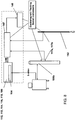
- FIG. 7 is a simplified schematic presenting an optional and exemplary arrangement of a system near a treatment bed, according to an embodiment of the present invention.
- a flat electromagnetic transmitter 148 is placed beneath bed mattress 155.
- a small (e.g. notebook) computer equipped with a frame grabbing card provides the functionality of controller 112 and its components as described herein.
- a sensor 117a is mounted on an ultrasound transducer 106b. Data flow is shown by dotted lines in the figure: ultrasound signals flow from transducer 106b to ultrasound unit 106a where images are visible on a screen. The video signal is also transferred to controller 112 where a frame grabbing card (not shown) digitizes images for use by controller 112's computational algorithms.
- Position information is transferred from sensor 117a to EM processing unit 147 and from there to controller 112. Positioning information is also transferred from sensor 117b in catheter 152 to controller 112. The software adds position information received from EM 147 to each of the images received from ultrasound in real time.
- FIG 8 presents an addition view of the system shown in Figure 6 , according to an embodiment of the invention.
- EM system 147 comprises a processing unit also labeled 147, a transmitter 148, and sensors117b (within catheter 152) and 117a (attached to transducer 106b).
- Ultrasound system 106 comprises a processing unit 106a, transducer 106b and an optional display.
- System controller 112 includes a frame grabbing card 164 and processors, software, memory, user interface data storage and data communications interface 116.
- Figure 9 is a simplified schematic illustrating registration of ultrasound image pixels in a 3D coordinate system, according to an embodiment of the present invention.
- the geometric arrangement shown in the figure allows position and orientation calculations and display of user-marked features on ultrasound images.
- EM transmitter 148 transmits a field detectable by sensor 117a.
- Vector A and the spatial orientation of point a are continuously measured by the EM system 147 in terms of a 3D coordinate system XYZ optionally with origin at transmitter 148.
- Sensor 117a measures six degrees of freedom of its position and orientation.
- Vector B connects between sensor 117a's location and point b, where b is any selected pixel on an ultrasound image.
- Point b is identified by its position in a local coordinate system UVW whose origin is at ultrasound transducer 106b.
- Vector B is measured through calibration or known from the technical data of the transducer (location and orientation of the imaging planes).
- Vector C1 is a vector in UVW along the ultrasound imaging plane from an identified pixel b up to a point of interest c1 .
- Standard ultrasound tools are used to obtain the calibration data, e.g. millimeters per pixel in both vertical and horizontal directions along the imaging plane. Alternatively calibration can be performed.
- the position in coordinate system XYZ of each such point of interest such as clor c2 is simply a vector summation of A + B + C .
- controller 112 calculates the location data for the marked feature (based on real-time sensor date reports) and saves the pixel data and the image location data substantially simultaneously. In this manner the spatial position of any point of interest (e.g. c1, c2) is calculated and stored in controller memory.
- a point of interest e.g. the position of a recognizable anatomical landmark
- Contours of the prostate at any selected spatial location can be calculated by interpolation between marked points (e.g. user-marked feature borders) such as c1. (Alternatively, direct 3Dinterpolation can be used, using the entire data set or using sets of slices.)
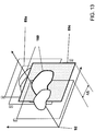
- Figure 10 illustrates contouring (segmentation) and 3D model creation, according to an embodiment of the present invention.
- Figure 10 illustrates the formation of cross-section contour 160 on slice image D of an organ such as a prostate.
- the user marks border points d1, d2, d3 , ..d7 , at least some of the 'slice' images presented by controller 112.
- Controller 112 then completes the contour using known curve-fitting methods (e.g. interpolation, spline). Marked data points for each cross section (each 'slice') are stored in the computer memory in the XYZ coordinate system.
- Figure 10 further illustrates the process of formation and illustration of a 3D model of the organ: cross-section contours on other planes 89a, (e.g. C, E, and F ) are made in a manner similar to that described for cross section D. Positions of marked border points in the XYZ coordinate system are known from location of b (see Figure 9 ), origin of the image plane for each slice, and from the unique vector (e.g. C1 ) to each marked or interpolated point.
- cross-section contours on other planes 89a e.g. C, E, and F
- Positions of marked border points in the XYZ coordinate system are known from location of b (see Figure 9 ), origin of the image plane for each slice, and from the unique vector (e.g. C1 ) to each marked or interpolated point.
- a full 3D model of the organ can be created using standard methods and then can be displayed on the controller display.
- EyeShot viewport control tools from devDept Software, Via Ugo Foscolo, 19, Zola Predosa, BO 40069, Italy, +039(051)7401811 is an example of a system which can create a full 3D model from such data.
- Figure 11 shows how, once a 3D model has been created, standard tools can be used for manipulations (rotation, translations, cross section etc.) on a display, to show any desired view.
- Figures 12A and 12B illustrated real-time presentation of a diagnostic tool or treatment tool in the context of a 3D model, according to embodiments of the present invention.
- sensor 117a detects position of transducer 106b.
- the position of needle cannula 106c with respect to transducer 106b is known, or can be determined by one-time calibration to observe the geometrical relation between the position of sensor 117 and the expected trajectory of a needle 171 passing through cannula 106C. Once this calculation is made, the expected real-time trajectory of an inserted needle can be presented on a display in the context of the 3D model.
- two sensors are used, one (117a) attached to transducer 106b and one (117b) attached to a proximal end an insertable needle 171 (or to a needle gun). Knowing or calibrating the distance between needle sensor 117c and the distal tip of needle 171 allows to calculate and to present on display, in the context of a 3D model of the organ, both the expected needle trajectory and also the real-time position of the needle tip 202.
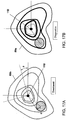
- Figure 13 illustrates handling of a situation where a prostate (or other organ) is displaced during the acquisition of images being used to create a 3D model, according to an embodiment of the present invention.
- a momentary displacement of the prostate is reflected in a slice image 89c in which the prostate profile has been displaced sideways.
- controller 112 uses standard mathematical tools to calculate the required translation of the image to its expected position between the other images, so that the process of creating a continuous 3D model of the prostate can continue as described above.
- Figures 14A-14D illustrates the "Fast 3D" method of creating a 3D model, according to embodiments of the present invention.
- Figure 14A illustrates a canonic model of a prostate, which model represents the three-dimensional shape of one typical type of prostate.
- the system comprises a plurality of such models in the memory or data storage of controller 112, each model optionally being a 3D surface-rendered model of a prostate and each representing one of the typical prostate sizes and shapes. These models are stored in the system memory in an arbitrary coordinate system X'Y'Z'.
- Each canonic model further comprises a plurality of pre-selected landmark locations which can serve as 'anchors' or 'handles' for geometrical manipulation of the model, and which are useful in fitting a canonical model to a 3D model based on real-time observation of a patient. According to the Applicant's current practice, six such points are used, as illustrated in exemplary manner in Figure 14B , but other numbers of points and other selections of points which are anatomically identifiable can be used.
- Figure 14B shows six points marked on two ultrasound images presented on display 114.
- the marked points are extremities seen on a transverse cross section and on a longitudinal cross section.
- the spatial locations of each of the six points is detected and recorded as explained above.
- Figure 14C shows how a user-selected canonical model may be 'fit' to a real-time model of a patient's prostate by stretching, squeezing, or otherwise graphically manipulating the model until the marked points of the model align with marked points on the real-time model (and/or on real-time 2D images of the organ).
- Figure 14D shows how graphically adapting the canonic model to the real-time model causes the canonic model to be expressed in the XYZ coordinate system which is expressive of the real-time location information. This makes the details of the canonic model available to the real-time operation after some simple graphical manipulations matching only six points between one model and the other.
- Controller 112 may have access to a data base containing a plurality of models of the prostate, enabling a physician to select a model that most closely approximates the prostate form that he observes, e.g. by selecting a model with similar proportions as measured by relative distances between specific marked points.
- Figures 15A-15J are simplified schematics presenting methods for aligning two 3D models that were created at different times and at different positions of the patient. These methods can be used in the context of procedures disclosed herein for diagnosing and treating an organ such as a prostate, according to aspects of the present invention.
- Figures 15A-15D present diagnostic-phase activities.
- Figure 15A presents an organ 104 such as a prostate 205 as imaged by a clinical imaging modality 106a which may be, for example, an ultrasound system.
- Prostate 205 traversed by a prostatic urethra 210, is shown as imaged in "slices", as is standard practice in ultrasound and other forms of prostatic imaging.
- Slices 220, 221, 222, 223 and 224 are shown, together with their contours 160.
- Three-dimensional model 90a of organ 104 and its environment based on a set of 'slice' such as images 220, 221, 222, 223 and 224 shown in Figure 15A .
- Such images are typically taken at known and regular intervals, such as every 5mm for example.
- Three-dimensional model 90a so produced constitutes a representation of organ 104 in a virtual three-dimensional space defined by a Cartesian coordinate system 92a or other coordinate system.
- Figure 15B shows fiducial markers 130, marked 130a, 130b, and 130c, inserted within organ 104.
- Figure 15C shows the taking of a plurality of biopsy tissue samples from locations 240a, 240b, 240c, 240d etc., using one or more biopsy probes 145.
- An embodiment of the invention comprises taking of samples from a plurality of sites well distributed throughout organ 104.
- Fiducial position markers 130 are designed to be visible under clinical imaging modalities 106a and 106b, enabling recording positions of sources of each biopsy sample taken. Positions may be identified with respect to positions of physiological landmarks, with respect to positions of markers 130, and/or with respect to a general coordinate system 92a of model 90a, within which fiducial markers 130 have known positions.
- Fiducial markers 130 may be permanent or semi-permanent markers inserted into the body for purpose of guiding therapy and then left in the body at the conclusion of the therapy.
- metal capsules may be used, such as the gold capsules supplied by Northwest Medical Physics Equipment under the trade name ACCULOC®.
- markers may be biodegradable.
- a marker according to embodiments of the present invention may be a bubble of biocompatible gas such as CO 2 enclosed in a biodegradable membrane 131 such as a biocompatible biodegradable polymer, which enclosed bubble would be visible under ultrasound imaging. Such a biodegradable marker would disappear over time, as the materials of which it is composed are absorbed by surrounding tissues or carried away by the blood stream.
- Figure 15D presents results of procedures described at 78 and 79 of Figure 2 , wherein sites which are sources for biopsy samples found to contain pathological tissues are marked for treatment in model 90a.
- biopsy sites 240b and 240c are labeled as treatment targets 250.
- Figures 15E-15J present treatment-phase activities corresponding to procedures 81, 82 and 84 of Figure 3 .
- Treatment-phase activity may take place hours or days after diagnostic phase activities.
- Treatment-phase activity comprises using imaging modalities 106b to create a set of second images 89b of target organ 104, as well as their contours 160 as shown in Figure 15E and described at 81 in Figure 3 .
- Procedures 81 of treatment-phase activity are similar to procedures 71 and 72 of Figure 2 of diagnostic phase activity.
- imaging modalities 106 are used to create a set of images 89 from which a 3-D model 90 is constructed.
- equipment used for diagnostic and for treatment phase activities may be same equipment, similar but separate equipment, or may be different equipment entirely.
- imaging modalities, processors, and algorithms for imaging and for creating three-dimensional models during diagnostic phase and during treatment phase may be identical or may be widely different.
- fiducial markers 130 are implanted during diagnostic phase activity, those markers are identified and their locations noted, as shown in Figure 15F as 130a, 130b, and 130c.
- Other objects introduced into the vicinity of organ 104 during diagnostic phase activity e.g. a urethral straightener discussed below, may be re-introduced during treatment-phase activity, and positions of these too will be noted.
- physiological landmarks may be identified algorithmically and/or these and markers 130 may be identified by a user through interface 113b.
- Figure 15G and 15H present phases of a process by which first and second images are related to each other.
- algorithmic procedures may be used to create first three-dimensional model 90a based on first images 89a, to create second three-dimensional model 90b based on second images 89b, and to relate first and second three dimensional models to each other in a common coordinate system 90c.
- Same objects e.g. images of the entire prostate, images of features of the prostate such as lobes, urethral entrance and exit, implanted fiducial markers, etc.
- same objects e.g. images of the entire prostate, images of features of the prostate such as lobes, urethral entrance and exit, implanted fiducial markers, etc.
- user intervention may be used to facilitate this process.
- a surgeon or other technician may be presented with displays of first and second images, and asked to identify physiological landmarks and/or fiducial markers in both images, thereby facilitating relating of first and second images and/or first and second 3-D models.
- a surgeon or technician may be enabled or instructed to manipulate imaging equipment such as ultrasound probes or other imaging modalities, so as to better align first and second images.
- graphic manipulation tools may be provided to a surgeon or technician enabling to relate first and second images one to another by graphic manipulation.
- Figure 15G and 15H any of the techniques mentioned in the preceding paragraphs and elsewhere herein may be used as indicated in Figures 15G and 15H , wherein first images 89a and second images 89b are aligned with each other, and/or first and second three-dimensional models 90a and 90b are mapped one to another.
- Figure 15I presents a result of these processes, wherein a common image 128 is generated, either by graphic manipulation of a first image 89a combined with a second image 89b, or by generation of combined image 128 directly from a combined three-dimensional model 90c which comprises information from first model 90a and from second model 90b mapped into a common model 90c having a (Cartesian or other) coordinate system 92c with a known relationship to coordinate systems 92a and 92b.
- a common image 128 is generated, either by graphic manipulation of a first image 89a combined with a second image 89b, or by generation of combined image 128 directly from a combined three-dimensional model 90c which comprises information
- common model 90c can comprise, and common image 128 can show, both diagnostic and real-time information.
- Common image 128 can show an organ 104 as positioned within a patient on an operating table ready for a surgical intervention, can show positions of treatment probes or other surgical tools used during the intervention, and can also graphically show locations of sites determined during diagnostic phase activities to be targets of the intervention. A surgeon is thus provided with a graphic presentation of a virtual space in which his patient, his tools, and his surgical targets are together visible.
- Figure 15J portrays a surgical intervention in progress, with intervention probes 146 and target loci 250 both visible on common image 128.
- combined information from models 90a and 90b are used to algorithmically direct intervention tools 146 towards surgical targets 250 under partial or complete algorithmic control. Relevant information is provided by control module 112b to servomotor controller 115b, which commands servomotor 119b and receives feedback from position sensor 117b, as discussed hereinabove. Position sensor 117b may be directly connected to treatment tool 146, or may alternatively be a remote sensor such as an ultrasound system and algorithmic detection system operable to detect position of tool 146 based on ultrasound images.
- fiducial markers 130 is optional. Such markers are a convenience in that they present easily visible positional signposts which facilitate aligning of first and second images and/or which facilitate relating a three-dimensional coordinate system of diagnostic 3-D model 90a based on first images with treatment 3-D model 90b based on second images. Procedures for relating first and second images may however be accomplished without requiring use of fiducial markers: physiological landmarks may be used instead to relate first images to second images.
- a prostate for example, size and relative positions of prostate lobes, positions of major portions of the prostate mass, positions of entrance of the urethral passageway into the prostate and its exit therefrom, and similar objects may be used as landmarks, visible and identifiable in both first and second images, to align first and second images and/or first and second 3-D models.
- User-supplied information such as user supplied identification of such landmarks on a raw ultrasound image or other image, may be used to facilitate this process.
- the system here presented enables to direct tools toward targets.
- Various options for guiding tools toward targets are contemplated. These include automated techniques, such as automated guidance based on directional information derived from comparison of recorded locations of targets in a first coordinate system 92a to an observed or detected position of a treatment tool in second images 89b, graphical techniques such as presenting recorded images of target locations combined with real-time images of tool positions in a combined graphic image 128 constructed using information deriving from both recorded diagnostic phase sources and real-time treatment phase sources, and other forms of assistance which may be provided to a surgeon, such as verbal or graphical instructions on how to orient an imaging modality (such as an ultrasound probe) to produce real-time images easily comparable to recorded images, verbal or graphical instructions on how to orient a stereotactic probe guide or other tool delivery system, and verbal or graphical instructions showing when to insert a probe, what direction to point it in, and how far to advance it.
- automated techniques such as automated guidance based on directional information derived from comparison of recorded locations of
- mapping three-dimensional model 90A to three-dimensional model 90b enables to combine information from these models even when the treated organ has moved or changed shape in the interval between diagnostic activity and treatment activity, and even if the first and second images are created by imaging probes which are differently placed or differently used between the two phases of activity, and even if entirely different imaging modalities are used during the different phases of activity.
- some embodiments comprise means for similarly constraining the form or position of a target organ both during diagnostic phase activities and during treatment phase activities, thereby enhancing similarity between first and second images and thereby facilitating relating of first and second images to each other and/or relating first and second 3-D models to each other.
- uterine manipulators previously used for stabilizing the uterus during treatment of nearby tissues, may be used for this purpose.
- a uterine manipulator called "LUMIN" marketed at www.utahmed.com/lumin.htm could be used to maintain similarity between diagnostic phase and therapy phase images, e.g. during diagnosis and later treatment of uterine fibroids.
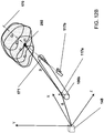
- Figures 16A, 16B are simplified schematics of a urethral straightener positioned within a prostate, according to an embodiment of the present invention.
- U.S. Patent Application 10/517,768 is referenced herein. That application teaches a urethral catheter with a straight section (or section with a known geometric form) which may be inserted into a prostatic urethra prior to imaging and/or treating a prostate. Such a catheter is referred to as a "urethral straightener" herein.
- the urethral straightener may have a section which is permanently straight (or with some other well-understood geometric form, such as a section of a circle with known diameter), or alternatively may be designed to be flexible when inserted, but to become stiff and of straight (or other known) form once inserted, e.g. through inflation of the catheter.
- a urethral straightener is contemplated in some aspects of the present invention.
- Use of a straightener during taking of both first and second images greatly increases similarities between the images and facilitates comparison of images and mapping of 3-D models one to another.
- use of such a urethral straighten enhances stiffness of the prostate, reducing 'noise' which would otherwise be introduced by random changes in prostate shape and position induced by gravity and by other influences, such as TRUS pressures on the organ.
- a urethral straightener can be provided with a sensor as described above for use with a urethral catheter, thereby combining straightening functionality and sensor functionality in a common tool.
- the inserted urethral straightener may be a rigid rod, preferably straight, or may have a flexible structure facilitating insertion, with capacity to be caused to straighten (e.g. by inflation under pressure) subsequent to insertion, as taught in U.S. Patent Application 10/517,768 .
- Figure 16A demonstrates use of an organ constraining device 255 exemplified as a urethral straightener 260, shown as inserted into the prostatic urethra 210 of a prostate 205, according to an embodiment of the present invention.
- Use of a urethral straightener inserted within the prostatic urethra is exemplary of "position standardization" of an organ or portion of an organ, and is exemplary of a general class of physical apparatus for constraining an organ, in a reproducible manner, to a predetermined form or position or condition or orientation.
- An organ constraining device 255, such as a urethral straightener 260 is optionally used during creation of both first images 89a and second images 89b, thereby facilitating comparisons of the two and facilitating relating of first images to second images.
- Figure 16B discloses another method of using the prostatic urethra as a landmark for enhanced mapping technique of the prostate, according to an embodiment of the present invention.
- the urethra, 210 can be easily identified under imaging.
- the urethra entrance to the bladder neck, 211, and the prostate-urethra end at the apex, 212 are two anatomical sites that can be identified and marked on the imaging screen during both a first session and a second session, their positions being recorded each time.
- Two or more such landmarks create as an imaginary line with clear relationship to the organ anatomy. Using this spatially recognized imaginary line, (213 in the figure) to align images or models from a first session with images or models from a second session greatly simplifies the use of other analytical tools and alignment algorithms.
- a first step for alignment between two models is to translate the first model to a position at which its imaginary fine, 213, fits the spatial location of the imaginary line, 213, of the second model.
- a second step is rotate one of the models around line 213, finding the the rotation angle at which the two models are best aligned. That angle is angle ⁇ as discussed below.
- Figures 17A and 17B are simplified schematics demonstrating comparison of first and second images created while using a urethral straightener, according to an embodiment of the present invention.
- a straightener simplify processing when comparing images by inducing a elements of uniformity between the first and second images, but also, with the prostatic urethra straightened, first and second images and/or first and second models may be easily aligned with the straight prostatic urethra as common longitudinal axis.
- Figures 17A and 17B presents comparison of a composite first image 89a with a composite second image 89b, the images being taken as if along the straightened urethra 110, shown centered in each image.
- An angle of rotation ⁇ of image 89b with respect to image 89a is easily determined by eye, by graphical rotation of one of the images around the urethra as axis, or by algorithmic comparison (e.g. by comparing positions of the largest imaged prostate lobe, the one having its border furthest from the prostate axis).
- contemplated embodiments may include facilities for manipulating the imaging equipment to enhance similarity of first and second images (e.g. by rotating an ultrasound probe to line up images 89a and 89b as shown in Figures 17A and 17B , or optionally by showing the images superimposed one on another and in different colors).
- Contemplated embodiments may also include facilities for graphically manipulating those images (i.e. manipulating the imaging presentation through a graphical user interface, rather than manipulating the imaging probe in a patient), and may also include algorithmic methods well known in the art for reducing dissimilarity between the images and recording the transformations required to do so.
- An additional optional embodiment comprises a device connectable to a urethral straightener on the one hand and to an imaging probe on the other hand, operable to standardize positioning of one with respect to the other during first and second imaging processes.
- position sensors mounted on a urethral straightener or position markers such as echogenic markers visible on a urethral straightener under ultrasound imaging, can also provide position and orientation information facilitating comparison of first and second images and mapping between first and second models.
- FIGS. 18A-18C are samples of output of a simulator running an algorithm appropriate for detecting angle ⁇ based on first and second image inputs shown in the Figures, the algorithm outputting instructions to a surgeon detailing how to position a stereotactic probe placement template so that probe positioning information based on first images will be usable on a prostate positioned as shown in second images.
- RMS scores may be calculated by calculating differences between a set of first image radial measurements starting at angle 0° and going around the first image, with a set of second image radial measurements starting at angle (0° plus an increasing factor) and going around the second image.
- comparison scores for all possible rotations need not be calculated since the range of possible actual rotations of the prostate images (between first image taking and second image taking) will be subject to practical limitations.
- three dimensional models 90a and 90b may be constructed using commercially available model construction software or other methods well known in the art (interpolation etc.), and then new sets of derived slice images derived from the 3D models may be created, again using well-known methods, and those derived first and second slice images may be compared.
- appropriate measurements of distances between urethra and prostate border may be derived directly from the models.
- Such methods are particularly important if no urethral straightener is used, since the urethral straightener can constrain orientation of the prostate around the urethral axis and/or can report the actual direction of a urethra within which a urethral straightener has been inserted.
- first and second images may typically differ in that an imaging modality (such as an ultrasound probe) may be closer to the prostate during imaging one set of images than it is during imaging of a second set of images, and thereby produce a larger set of images. Integrating the radial measurements over the entire prostate for both first and second images (or models) will yield first and second integral values corresponding to an apparent prostate "volume" as shown in the image sets. The ratio of the apparent volume of the first images divided by the apparent volume of the second images represents the relative "enlargement" of one of the sets of images with respect to the other. This information may be used to normalize the two sets of images (or models) to a common apparent size, thereby facilitating calculations and facilitating the creating of composite image 128 if desired.
- an imaging modality such as an ultrasound probe
- range format is merely for convenience and brevity and should not be construed as an inflexible limitation on the scope of the invention. Accordingly, the description of a range should be considered to have specifically disclosed all the possible subranges as well as individual numerical values within that range. For example, description of a range such as from 1 to 6 should be considered to have specifically disclosed subranges such as from 1 to 3, from 1 to 4, from 1 to 5, from 2 to 4, from 2 to 6, from 3 to 6 etc., as well as individual numbers within that range, for example, 1, 2, 3, 4, 5, and 6. This applies regardless of the breadth of the range.
- method refers to manners, means, techniques and procedures for accomplishing a given task including, but not limited to, those manners, means, techniques and procedures either known to, or readily developed from known manners, means, techniques and procedures by practitioners of the chemical, pharmacological, biological, biochemical and medical arts.
Landscapes
- Health & Medical Sciences (AREA)
- Life Sciences & Earth Sciences (AREA)
- Engineering & Computer Science (AREA)
- Medical Informatics (AREA)
- Surgery (AREA)
- Pathology (AREA)
- Veterinary Medicine (AREA)
- Public Health (AREA)
- Biomedical Technology (AREA)
- Heart & Thoracic Surgery (AREA)
- General Health & Medical Sciences (AREA)
- Molecular Biology (AREA)
- Animal Behavior & Ethology (AREA)
- Physics & Mathematics (AREA)
- Biophysics (AREA)
- Nuclear Medicine, Radiotherapy & Molecular Imaging (AREA)
- Radiology & Medical Imaging (AREA)
- Human Computer Interaction (AREA)
- Ultra Sonic Daignosis Equipment (AREA)
- Measuring And Recording Apparatus For Diagnosis (AREA)
- Apparatus For Radiation Diagnosis (AREA)
Claims (3)
- System zum Orten von Läsionen in einer Prostata während einer ersten Interventionssitzung und zum Verwenden dieser Läsionsortungsinformationen während einer zweiten Interventionssitzung, wobei das System umfasst:a. ein erstes 3D-Modellierungsmodul, das ein erstes 3D-Modell der Prostata auf Grundlage zumindest zum Teil von Echtzeit-Ultraschallabbildung der Prostata während der ersten Interventionssitzung erzeugt;b. ein Interventionsaufzeichnungsmodul, das Positionen mehrerer Biopsieproben aufzeichnet, die während der ersten Interventionssitzung genommen werden, wobei die Position der Proben in Bezug auf das 3D-Modell aufgezeichnet wird;c. ein Diagnoseaufzeichnungsmodul zum Aufzeichnen von Positionen mindestens einer Läsion, die durch Pathologieuntersuchungen der Biopsieproben entdeckt wurde, wobei die Läsionspositionen in Bezug auf das erste 3D-Modell aufgezeichnet werden;d. ein zweites 3D-Modellierungsmodul, das ein zweites 3D-Modell der Prostata auf Grundlage zumindest zum Teil von Echtzeit-Ultraschallabbildung der Prostata während der zweiten Interventionssitzung erzeugt;e. ein Läsionspositionsberechnungsmodul, das Positionen der entdeckten Läsionen in Bezug auf das zweite 3D-Modell auf Grundlage von durch das Diagnoseaufzeichnungsmodul aufgezeichneten Positionen und darüber hinaus auf Grundlage von Positionsverhältnissen zwischen dem ersten 3D-Modell und dem zweiten 3D-Modell berechnet; undf. ein Anzeigemodul, das die berechneten Läsionspositionen im Zusammenhang mit der Prostataechtzeitposition des Patienten anzeigt, wodurch es einem Chirurgen ermöglicht wird, therapeutische Eingriffe während der zweiten Interventionssitzung entsprechend der Läsionsortungsinformationen zu leiten, die während der ersten Interventionssitzung und während einer Analyse von Biopsien gewonnen wurden, die während der ersten Interventionssitzung entnommen wurden, und:g. ein Modul zum Erfassen und Melden der Position einer Prostata in Echtzeit, das einen oder mehrere Sender für elektronische Signale, der bzw. die nahe einem Patienten positionierbar ist bzw. sind, und einen Sensor zum Erfassen und Melden der Position des Sensors in Bezug auf die durch die Sender übertragenen elektronischen Signale umfasst,wobei das System dadurch gekennzeichnet ist, dass der Sensor an einem Foley-Katheter vorgesehen ist, der einen distalen Ballon, der innerhalb einer Blase aufblasbar ist, um ein distales Ende des Katheters zu immobilisieren, und eine 'Rücklaufstopp'-Immobilisierungsvorrichtung umfasst, um einen proximalen Abschnitt des Katheters am Eingang zur Urethra zu immobilisieren, wobei die Immobilisierungsvorrichtungen den Sensor in der Prostata an einer bekannten und feststehenden Position zwischen dem distalen Katheter-Ende am Blaseneingang und dem Urethra-Eingang am Apex der Prostata immobilisieren.
- System nach Anspruch 1, darüber hinaus ein Bildregistrierungssystem umfassend, um 3D-Modellinformationen der ersten Sitzung auf einem 3D-Modell der zweiten Sitzung durch einen (benutzerunterstützten oder algorithmischen) Vergleich der Ortung erkennbarer physiologischer markanter Punkte von jedem Modell im Körper abzubilden, welches Bildregistrierungssystem umfasst:(i) eine Benutzerschnittstelle, die grafische Hilfsmittel umfasst, mit denen ein Benutzer auf einem ersten Bild, das von der Echtzeitabbildung der Prostata während der ersten Intervention abgeleitet ist, und auf einem zweiten Bild, das von der Echtzeitabbildung der Prostata während der zweiten Intervention abgeleitet ist, beobachtete Position von blasenseitigen und apexseitigen Extremitäten der prostatischen Urethra markieren kann, wodurch eine Prostata-Achse festgelegt wird, die sich zwischen den markierten Positionen der prostatischen Urethra-Extremitäten in jedem Bild erstreckt; und(ii) ein Modellausrichtungsmodul, das dazu programmiert ist, das erste und zweite 3D-Modell auszurichten durch- Markieren der Prostata-Achsen am ersten und zweiten 3D-Modell;- Überlagern des ersten 3D-Modells am zweiten 3D-Modell in einem gemeinsamen virtuellen Raum;- Drehen und Größenanpassen des ersten 3D-Modells so, dass sich die Prostata-Achse des ersten Modells auf der Prostata-Achse des zweiten Modells befindet;- Drehen der ersten Modells schrittweise um die Prostata-Achse des ersten Modells, um einen Satz gedrehter Ansichten des ersten Modells zu erzeugen, und Berechnen für jede derartige Ansicht eines Maßes eines Unterschieds zwischen der gedrehten Ansicht des ersten Modells und dem nicht gedrehten zweiten Modell;- Auswählen von derjenigen gedrehten Ansicht des ersten Modells, für welche das berechnete Maß der Unterschiede am kleinsten ist; und- Übertragen von im ersten Modell aufgezeichneten Datenpositionen in ihren gedrehten Positionen in der ausgewählten gedrehten Ansicht auf entsprechende Positionen im zweiten Modell.
- System nach Anspruch 1 oder 2, darüber hinaus ein Prostatamodellierungserleichterungshilfsmittel umfassend, das umfasst:(i) einen Satz vordefinierter 3D-Modelle der Prostata, wobei jedes der vordefinierten Modelle eine typische Art von Prostataform darstellt und jedes Modell bestimmte Positionen für Blasenend- und Apexend-Extremitäten der urethralen Prostata umfasst; und(ii) eine Schnittstelle, die betätigbar ist, um Echtzeitbilder der Prostata des Patienten und auch grafische Anzeigen der vordefinierten Prostatamodelle darzustellen, und wobei der Benutzer aus dem Satz vordefinierter Modelle das Modell auswählen kann, das seiner Meinung nach der Form der Prostata des Patienten am meisten ähnelt,und wobei das erste und zweite Modellierungsmodul das ausgewählte vordefinierte 3D-Modell beim Aufbauen des ersten und zweiten 3D-Modells nutzen.
Applications Claiming Priority (2)
| Application Number | Priority Date | Filing Date | Title |
|---|---|---|---|
| US35803410P | 2010-06-24 | 2010-06-24 | |
| PCT/IL2011/000507 WO2011161684A2 (en) | 2010-06-24 | 2011-06-23 | Focused prostate cancer treatment system and method |
Publications (2)
| Publication Number | Publication Date |
|---|---|
| EP2584990A2 EP2584990A2 (de) | 2013-05-01 |
| EP2584990B1 true EP2584990B1 (de) | 2019-04-24 |
Family
ID=44514871
Family Applications (1)
| Application Number | Title | Priority Date | Filing Date |
|---|---|---|---|
| EP11738824.9A Active EP2584990B1 (de) | 2010-06-24 | 2011-06-23 | System für fokussierte prostatakrebsbehandlung |
Country Status (3)
| Country | Link |
|---|---|
| US (1) | US9392960B2 (de) |
| EP (1) | EP2584990B1 (de) |
| WO (1) | WO2011161684A2 (de) |
Families Citing this family (55)
| Publication number | Priority date | Publication date | Assignee | Title |
|---|---|---|---|---|
| US11612377B2 (en) * | 2010-12-16 | 2023-03-28 | Best Medical International, Inc. | Image guided surgical methodology and system employing patient movement detection and correction |
| US20120253170A1 (en) * | 2011-03-29 | 2012-10-04 | Samsung Electronics Co., Ltd. | Method and apparatus for generating medical image of body organ by using 3-d model |
| US20120290976A1 (en) * | 2011-05-13 | 2012-11-15 | Medtronic, Inc. | Network distribution of anatomical models |
| US9098611B2 (en) * | 2012-11-26 | 2015-08-04 | Intouch Technologies, Inc. | Enhanced video interaction for a user interface of a telepresence network |
| US9179890B2 (en) * | 2011-07-14 | 2015-11-10 | Siemens Aktiengesellschaft | Model-based positioning for intracardiac echocardiography volume stitching |
| JP5918862B2 (ja) | 2012-01-10 | 2016-05-18 | ユーシー—ケア リミテッド. | 生物組織ハンドリング装置および方法 |
| US9892557B2 (en) | 2012-01-26 | 2018-02-13 | Uc-Care Ltd. | Integrated system for focused treatment and methods thereof |
| JP6106259B2 (ja) * | 2012-03-21 | 2017-03-29 | コーニンクレッカ フィリップス エヌ ヴェKoninklijke Philips N.V. | 医用イメージングと生検データとを統合する臨床ワークステーション及びこれを使用する方法 |
| FR2991160B1 (fr) * | 2012-06-01 | 2015-05-15 | Koelis | Dispositif de guidage d’une sonde d’imagerie medicale, sonde d’imagerie medicale adaptee a etre guidee par un tel dispositif et procede de guidage d’une telle sonde. |
| US9655595B2 (en) * | 2012-06-14 | 2017-05-23 | Arcitrax Inc. | System, method and device for prostate diagnosis and intervention |
| US20150238276A1 (en) * | 2012-09-30 | 2015-08-27 | M.S.T. Medical Surgery Technologies Ltd. | Device and method for assisting laparoscopic surgery - directing and maneuvering articulating tool |
| EP2928559B1 (de) | 2012-12-06 | 2017-10-25 | Koninklijke Philips N.V. | Kalibrierungsvorrichtung |
| CN105163684B (zh) | 2013-03-15 | 2018-02-02 | 圣纳普医疗(巴巴多斯)公司 | 手术数据的联运同步 |
| US10092279B2 (en) | 2013-03-15 | 2018-10-09 | Uc-Care Ltd. | System and methods for processing a biopsy sample |
| US10716536B2 (en) | 2013-07-17 | 2020-07-21 | Tissue Differentiation Intelligence, Llc | Identifying anatomical structures |
| US10154826B2 (en) | 2013-07-17 | 2018-12-18 | Tissue Differentiation Intelligence, Llc | Device and method for identifying anatomical structures |
| US20150033172A1 (en) * | 2013-07-24 | 2015-01-29 | Concurix Corporation | Timeline Charts with Subgraphs |
| KR102205898B1 (ko) * | 2013-09-04 | 2021-01-21 | 삼성전자주식회사 | 의료영상들을 정합하는 방법 및 장치 |
| KR20150074304A (ko) * | 2013-12-23 | 2015-07-02 | 삼성전자주식회사 | 의료 영상 정보를 제공하는 방법 및 그 장치 |
| WO2015140782A1 (en) * | 2014-03-18 | 2015-09-24 | Doron Kwiat | Biopsy method and clinic for imaging and biopsy |
| US11547499B2 (en) * | 2014-04-04 | 2023-01-10 | Surgical Theater, Inc. | Dynamic and interactive navigation in a surgical environment |
| JP6566714B2 (ja) * | 2014-05-19 | 2019-08-28 | キヤノンメディカルシステムズ株式会社 | X線コンピュータ断層撮影装置、画像表示装置および画像表示方法 |
| US9717443B2 (en) * | 2014-06-12 | 2017-08-01 | Coloplast A/S | Surgical tool and method for identifying an incision site |
| US9717578B2 (en) * | 2014-06-12 | 2017-08-01 | Coloplast A/S | Surgical tool adapted for identifying an incision site |
| JP6716538B2 (ja) | 2014-07-28 | 2020-07-01 | インテュイティブ サージカル オペレーションズ, インコーポレイテッド | 多数のインターベンショナル処置を計画するシステム及び方法 |
| CN106794011B (zh) * | 2014-08-23 | 2020-11-27 | 直观外科手术操作公司 | 用于在图像引导程序中显示病理数据的系统和方法 |
| CN106999246B (zh) * | 2014-10-17 | 2020-12-08 | 皇家飞利浦有限公司 | 介入治疗系统和用于对叠加的图像进行绘制的方法 |
| US20160310043A1 (en) * | 2015-04-26 | 2016-10-27 | Endochoice, Inc. | Endoscopic Polyp Measurement Tool and Method for Using the Same |
| US10269114B2 (en) | 2015-06-12 | 2019-04-23 | International Business Machines Corporation | Methods and systems for automatically scoring diagnoses associated with clinical images |
| JP6750194B2 (ja) * | 2015-06-19 | 2020-09-02 | ソニー株式会社 | 医療用画像処理装置、医療用画像処理方法、及び、医療用観察システム |
| WO2017156023A1 (en) * | 2016-03-07 | 2017-09-14 | Avaz Surgical, Llc | Identifying anatomical structures |
| US11986341B1 (en) | 2016-05-26 | 2024-05-21 | Tissue Differentiation Intelligence, Llc | Methods for accessing spinal column using B-mode imaging to determine a trajectory without penetrating the the patient's anatomy |
| US11701086B1 (en) | 2016-06-21 | 2023-07-18 | Tissue Differentiation Intelligence, Llc | Methods and systems for improved nerve detection |
| US10201389B2 (en) * | 2016-10-31 | 2019-02-12 | Edda Technology, Inc. | Method and system for interactive grid placement and measurements for lesion removal |
| US10980509B2 (en) * | 2017-05-11 | 2021-04-20 | Siemens Medical Solutions Usa, Inc. | Deformable registration of preoperative volumes and intraoperative ultrasound images from a tracked transducer |
| WO2019010232A1 (en) * | 2017-07-07 | 2019-01-10 | Canon U.S.A. Inc. | MULTI-PROBE ABLATION PLANNING |
| US11197723B2 (en) | 2017-10-09 | 2021-12-14 | Canon U.S.A., Inc. | Medical guidance system and method using localized insertion plane |
| US10832808B2 (en) | 2017-12-13 | 2020-11-10 | International Business Machines Corporation | Automated selection, arrangement, and processing of key images |
| SG11202005483XA (en) * | 2017-12-28 | 2020-07-29 | Changi General Hospital Pte Ltd | Motion compensation platform for image guided percutaneous access to bodily organs and structures |
| US11754712B2 (en) | 2018-07-16 | 2023-09-12 | Cilag Gmbh International | Combination emitter and camera assembly |
| US11745354B2 (en) | 2018-08-16 | 2023-09-05 | Mitutoyo Corporation | Supplementary metrology position coordinates determination system including an alignment sensor for use with a robot |
| US10871366B2 (en) | 2018-08-16 | 2020-12-22 | Mitutoyo Corporation | Supplementary metrology position coordinates determination system for use with a robot |
| US10751883B2 (en) * | 2018-08-16 | 2020-08-25 | Mitutoyo Corporation | Robot system with supplementary metrology position coordinates determination system |
| US11002529B2 (en) | 2018-08-16 | 2021-05-11 | Mitutoyo Corporation | Robot system with supplementary metrology position determination system |
| US10913156B2 (en) | 2018-09-24 | 2021-02-09 | Mitutoyo Corporation | Robot system with end tool metrology position coordinates determination system |
| WO2020226693A1 (en) | 2019-05-03 | 2020-11-12 | Neil Glossop | Systems, methods, and devices for registering and tracking organs during interventional procedures |
| US20210068750A1 (en) * | 2019-09-09 | 2021-03-11 | 3Dbiopsy, Inc. | Three-Dimensional Biopsy Imaging and Planning System and Method |
| US20210085211A1 (en) * | 2019-09-24 | 2021-03-25 | Covidien Lp | Systems and methods for image-guided navigation of percutaneously- inserted devices |
| US11896442B2 (en) | 2019-12-30 | 2024-02-13 | Cilag Gmbh International | Surgical systems for proposing and corroborating organ portion removals |
| US11832996B2 (en) | 2019-12-30 | 2023-12-05 | Cilag Gmbh International | Analyzing surgical trends by a surgical system |
| US11284963B2 (en) | 2019-12-30 | 2022-03-29 | Cilag Gmbh International | Method of using imaging devices in surgery |
| US11776144B2 (en) | 2019-12-30 | 2023-10-03 | Cilag Gmbh International | System and method for determining, adjusting, and managing resection margin about a subject tissue |
| US11759283B2 (en) | 2019-12-30 | 2023-09-19 | Cilag Gmbh International | Surgical systems for generating three dimensional constructs of anatomical organs and coupling identified anatomical structures thereto |
| US11744667B2 (en) | 2019-12-30 | 2023-09-05 | Cilag Gmbh International | Adaptive visualization by a surgical system |
| US20220409167A1 (en) * | 2021-06-24 | 2022-12-29 | Biosense Webster (Israel) Ltd. | Visualization of 4d ultrasound maps |
Family Cites Families (5)
| Publication number | Priority date | Publication date | Assignee | Title |
|---|---|---|---|---|
| FR2639238B1 (fr) | 1988-11-21 | 1991-02-22 | Technomed Int Sa | Appareil de traitement chirurgical de tissus par hyperthermie, de preference la prostate, comprenant des moyens de protection thermique comprenant de preference des moyens formant ecran radioreflechissant |
| US7670333B2 (en) | 2002-06-27 | 2010-03-02 | Uc-Care Ltd. | Method and apparatus for positioning a surgical instrument |
| US20090287223A1 (en) * | 2006-07-11 | 2009-11-19 | Eric Pua | Real-time 3-d ultrasound guidance of surgical robotics |
| US20090048515A1 (en) | 2007-08-14 | 2009-02-19 | Suri Jasjit S | Biopsy planning system |
| FR2920961B1 (fr) | 2007-09-18 | 2017-06-02 | Koelis | Systeme et procede d'imagerie et de localisation de ponctions sous echographie prostatique |
-
2011
- 2011-06-23 EP EP11738824.9A patent/EP2584990B1/de active Active
- 2011-06-23 WO PCT/IL2011/000507 patent/WO2011161684A2/en active Application Filing
- 2011-06-23 US US13/805,535 patent/US9392960B2/en active Active
Non-Patent Citations (1)
| Title |
|---|
| None * |
Also Published As
| Publication number | Publication date |
|---|---|
| US9392960B2 (en) | 2016-07-19 |
| EP2584990A2 (de) | 2013-05-01 |
| WO2011161684A3 (en) | 2012-04-12 |
| WO2011161684A2 (en) | 2011-12-29 |
| US20130090554A1 (en) | 2013-04-11 |
Similar Documents
| Publication | Publication Date | Title |
|---|---|---|
| EP2584990B1 (de) | System für fokussierte prostatakrebsbehandlung | |
| JP7483271B2 (ja) | テンプレート化されターゲット化されたバイオプシと処置のためのガイダンス及びトラッキングシステム | |
| US10265137B2 (en) | Systems, methods, and devices for assisting or performing guided interventional procedures using custom templates | |
| US9681919B2 (en) | Systems, methods, and devices for assisting or performing guided interventional procedures using custom templates | |
| Boctor et al. | Three‐dimensional ultrasound‐guided robotic needle placement: an experimental evaluation | |
| CN105208958B (zh) | 用于微创治疗的导航和模拟的系统和方法 | |
| US6731966B1 (en) | Systems and methods for targeting a lesion | |
| US11766298B2 (en) | Systems, methods, and devices for registering and tracking organs during interventional procedures | |
| US20110009748A1 (en) | Transperineal prostate biopsy system and methods | |
| CN110811835A (zh) | 计算机断层扫描增强的荧光透视系统、装置及其使用方法 | |
| JP2009078144A (ja) | 副鼻洞形成術ナビゲーションのためのフルオロスコープと計算機式断層写真法との位置揃えのシステム及び利用方法 | |
| JP2008126063A (ja) | フルオロスコピィ画像投影への用具及び/又は埋植物の統合を備えた医用ナビゲーション・システム並びに方法 | |
| JP7221190B2 (ja) | 最適化されたデバイス対画像の位置合わせのための構造マスキングまたはアンマスキング | |
| Mohareri et al. | Automatic localization of the da Vinci surgical instrument tips in 3-D transrectal ultrasound | |
| WO2015148529A1 (en) | Interactive systems and methods for real-time laparoscopic navigation | |
| US10682126B2 (en) | Phantom to determine positional and angular navigation system error | |
| Adebar et al. | Registration of 3D ultrasound through an air–tissue boundary | |
| WO2016135595A1 (en) | Indirect visualization-assisted apparatus and method for positioning medical instruments | |
| EP3261551A1 (de) | Durch indirekte visualisierung unterstützte vorrichtung und verfahren zur positionierung medizinischer instrumente | |
| US20230090468A1 (en) | Systems, methods, and devices for registering and tracking organs during interventional procedures | |
| CN113907883A (zh) | 一种耳侧颅底外科3d可视化手术导航系统及方法 | |
| Troccaz et al. | Medical image computing and computer-aided medical interventions applied to soft tissues: Work in progress in urology | |
| Maier-Hein et al. | Soft tissue navigation using needle-shaped markers: Evaluation of navigation aid tracking accuracy and CT registration | |
| KR20210086871A (ko) | 의료 영상을 이용하는 중재시술 시스템 및 방법 | |
| Venix | The feasibility of EM navigation for gynecologic brachytherapy catheter insertion |
Legal Events
| Date | Code | Title | Description |
|---|---|---|---|
| PUAI | Public reference made under article 153(3) epc to a published international application that has entered the european phase |
Free format text: ORIGINAL CODE: 0009012 |
|
| 17P | Request for examination filed |
Effective date: 20130124 |
|
| AK | Designated contracting states |
Kind code of ref document: A2 Designated state(s): AL AT BE BG CH CY CZ DE DK EE ES FI FR GB GR HR HU IE IS IT LI LT LU LV MC MK MT NL NO PL PT RO RS SE SI SK SM TR |
|
| DAX | Request for extension of the european patent (deleted) | ||
| 17Q | First examination report despatched |
Effective date: 20151214 |
|
| STAA | Information on the status of an ep patent application or granted ep patent |
Free format text: STATUS: EXAMINATION IS IN PROGRESS |
|
| REG | Reference to a national code |
Ref country code: DE Ref legal event code: R079 Ref document number: 602011058308 Country of ref document: DE Free format text: PREVIOUS MAIN CLASS: A61B0019000000 Ipc: A61B0010020000 |
|
| GRAP | Despatch of communication of intention to grant a patent |
Free format text: ORIGINAL CODE: EPIDOSNIGR1 |
|
| STAA | Information on the status of an ep patent application or granted ep patent |
Free format text: STATUS: GRANT OF PATENT IS INTENDED |
|
| RIC1 | Information provided on ipc code assigned before grant |
Ipc: A61B 10/02 20060101AFI20181005BHEP |
|
| INTG | Intention to grant announced |
Effective date: 20181105 |
|
| GRAS | Grant fee paid |
Free format text: ORIGINAL CODE: EPIDOSNIGR3 |
|
| GRAA | (expected) grant |
Free format text: ORIGINAL CODE: 0009210 |
|
| STAA | Information on the status of an ep patent application or granted ep patent |
Free format text: STATUS: THE PATENT HAS BEEN GRANTED |
|
| AK | Designated contracting states |
Kind code of ref document: B1 Designated state(s): AL AT BE BG CH CY CZ DE DK EE ES FI FR GB GR HR HU IE IS IT LI LT LU LV MC MK MT NL NO PL PT RO RS SE SI SK SM TR |
|
| REG | Reference to a national code |
Ref country code: GB Ref legal event code: FG4D |
|
| REG | Reference to a national code |
Ref country code: CH Ref legal event code: EP |
|
| REG | Reference to a national code |
Ref country code: DE Ref legal event code: R096 Ref document number: 602011058308 Country of ref document: DE |
|
| REG | Reference to a national code |
Ref country code: AT Ref legal event code: REF Ref document number: 1123169 Country of ref document: AT Kind code of ref document: T Effective date: 20190515 Ref country code: IE Ref legal event code: FG4D |
|
| REG | Reference to a national code |
Ref country code: NL Ref legal event code: MP Effective date: 20190424 |
|
| REG | Reference to a national code |
Ref country code: LT Ref legal event code: MG4D |
|
| PG25 | Lapsed in a contracting state [announced via postgrant information from national office to epo] |
Ref country code: NL Free format text: LAPSE BECAUSE OF FAILURE TO SUBMIT A TRANSLATION OF THE DESCRIPTION OR TO PAY THE FEE WITHIN THE PRESCRIBED TIME-LIMIT Effective date: 20190424 |
|
| PG25 | Lapsed in a contracting state [announced via postgrant information from national office to epo] |
Ref country code: AL Free format text: LAPSE BECAUSE OF FAILURE TO SUBMIT A TRANSLATION OF THE DESCRIPTION OR TO PAY THE FEE WITHIN THE PRESCRIBED TIME-LIMIT Effective date: 20190424 Ref country code: PT Free format text: LAPSE BECAUSE OF FAILURE TO SUBMIT A TRANSLATION OF THE DESCRIPTION OR TO PAY THE FEE WITHIN THE PRESCRIBED TIME-LIMIT Effective date: 20190824 Ref country code: LT Free format text: LAPSE BECAUSE OF FAILURE TO SUBMIT A TRANSLATION OF THE DESCRIPTION OR TO PAY THE FEE WITHIN THE PRESCRIBED TIME-LIMIT Effective date: 20190424 Ref country code: FI Free format text: LAPSE BECAUSE OF FAILURE TO SUBMIT A TRANSLATION OF THE DESCRIPTION OR TO PAY THE FEE WITHIN THE PRESCRIBED TIME-LIMIT Effective date: 20190424 Ref country code: NO Free format text: LAPSE BECAUSE OF FAILURE TO SUBMIT A TRANSLATION OF THE DESCRIPTION OR TO PAY THE FEE WITHIN THE PRESCRIBED TIME-LIMIT Effective date: 20190724 Ref country code: SE Free format text: LAPSE BECAUSE OF FAILURE TO SUBMIT A TRANSLATION OF THE DESCRIPTION OR TO PAY THE FEE WITHIN THE PRESCRIBED TIME-LIMIT Effective date: 20190424 Ref country code: HR Free format text: LAPSE BECAUSE OF FAILURE TO SUBMIT A TRANSLATION OF THE DESCRIPTION OR TO PAY THE FEE WITHIN THE PRESCRIBED TIME-LIMIT Effective date: 20190424 Ref country code: ES Free format text: LAPSE BECAUSE OF FAILURE TO SUBMIT A TRANSLATION OF THE DESCRIPTION OR TO PAY THE FEE WITHIN THE PRESCRIBED TIME-LIMIT Effective date: 20190424 |
|
| PG25 | Lapsed in a contracting state [announced via postgrant information from national office to epo] |
Ref country code: LV Free format text: LAPSE BECAUSE OF FAILURE TO SUBMIT A TRANSLATION OF THE DESCRIPTION OR TO PAY THE FEE WITHIN THE PRESCRIBED TIME-LIMIT Effective date: 20190424 Ref country code: RS Free format text: LAPSE BECAUSE OF FAILURE TO SUBMIT A TRANSLATION OF THE DESCRIPTION OR TO PAY THE FEE WITHIN THE PRESCRIBED TIME-LIMIT Effective date: 20190424 Ref country code: PL Free format text: LAPSE BECAUSE OF FAILURE TO SUBMIT A TRANSLATION OF THE DESCRIPTION OR TO PAY THE FEE WITHIN THE PRESCRIBED TIME-LIMIT Effective date: 20190424 Ref country code: BG Free format text: LAPSE BECAUSE OF FAILURE TO SUBMIT A TRANSLATION OF THE DESCRIPTION OR TO PAY THE FEE WITHIN THE PRESCRIBED TIME-LIMIT Effective date: 20190724 Ref country code: GR Free format text: LAPSE BECAUSE OF FAILURE TO SUBMIT A TRANSLATION OF THE DESCRIPTION OR TO PAY THE FEE WITHIN THE PRESCRIBED TIME-LIMIT Effective date: 20190725 |
|
| REG | Reference to a national code |
Ref country code: AT Ref legal event code: MK05 Ref document number: 1123169 Country of ref document: AT Kind code of ref document: T Effective date: 20190424 |
|
| PG25 | Lapsed in a contracting state [announced via postgrant information from national office to epo] |
Ref country code: IS Free format text: LAPSE BECAUSE OF FAILURE TO SUBMIT A TRANSLATION OF THE DESCRIPTION OR TO PAY THE FEE WITHIN THE PRESCRIBED TIME-LIMIT Effective date: 20190824 |
|
| REG | Reference to a national code |
Ref country code: DE Ref legal event code: R082 Ref document number: 602011058308 Country of ref document: DE Representative=s name: 2K PATENT- UND RECHTSANWAELTE PARTNERSCHAFT MB, DE |
|
| REG | Reference to a national code |
Ref country code: DE Ref legal event code: R097 Ref document number: 602011058308 Country of ref document: DE |
|
| PG25 | Lapsed in a contracting state [announced via postgrant information from national office to epo] |
Ref country code: MC Free format text: LAPSE BECAUSE OF FAILURE TO SUBMIT A TRANSLATION OF THE DESCRIPTION OR TO PAY THE FEE WITHIN THE PRESCRIBED TIME-LIMIT Effective date: 20190424 Ref country code: CZ Free format text: LAPSE BECAUSE OF FAILURE TO SUBMIT A TRANSLATION OF THE DESCRIPTION OR TO PAY THE FEE WITHIN THE PRESCRIBED TIME-LIMIT Effective date: 20190424 Ref country code: DK Free format text: LAPSE BECAUSE OF FAILURE TO SUBMIT A TRANSLATION OF THE DESCRIPTION OR TO PAY THE FEE WITHIN THE PRESCRIBED TIME-LIMIT Effective date: 20190424 Ref country code: AT Free format text: LAPSE BECAUSE OF FAILURE TO SUBMIT A TRANSLATION OF THE DESCRIPTION OR TO PAY THE FEE WITHIN THE PRESCRIBED TIME-LIMIT Effective date: 20190424 Ref country code: RO Free format text: LAPSE BECAUSE OF FAILURE TO SUBMIT A TRANSLATION OF THE DESCRIPTION OR TO PAY THE FEE WITHIN THE PRESCRIBED TIME-LIMIT Effective date: 20190424 Ref country code: EE Free format text: LAPSE BECAUSE OF FAILURE TO SUBMIT A TRANSLATION OF THE DESCRIPTION OR TO PAY THE FEE WITHIN THE PRESCRIBED TIME-LIMIT Effective date: 20190424 Ref country code: SK Free format text: LAPSE BECAUSE OF FAILURE TO SUBMIT A TRANSLATION OF THE DESCRIPTION OR TO PAY THE FEE WITHIN THE PRESCRIBED TIME-LIMIT Effective date: 20190424 |
|
| REG | Reference to a national code |
Ref country code: CH Ref legal event code: PL |
|
| PG25 | Lapsed in a contracting state [announced via postgrant information from national office to epo] |
Ref country code: IT Free format text: LAPSE BECAUSE OF FAILURE TO SUBMIT A TRANSLATION OF THE DESCRIPTION OR TO PAY THE FEE WITHIN THE PRESCRIBED TIME-LIMIT Effective date: 20190424 Ref country code: SM Free format text: LAPSE BECAUSE OF FAILURE TO SUBMIT A TRANSLATION OF THE DESCRIPTION OR TO PAY THE FEE WITHIN THE PRESCRIBED TIME-LIMIT Effective date: 20190424 |
|
| PLBE | No opposition filed within time limit |
Free format text: ORIGINAL CODE: 0009261 |
|
| STAA | Information on the status of an ep patent application or granted ep patent |
Free format text: STATUS: NO OPPOSITION FILED WITHIN TIME LIMIT |
|
| REG | Reference to a national code |
Ref country code: BE Ref legal event code: MM Effective date: 20190630 |
|
| PG25 | Lapsed in a contracting state [announced via postgrant information from national office to epo] |
Ref country code: TR Free format text: LAPSE BECAUSE OF FAILURE TO SUBMIT A TRANSLATION OF THE DESCRIPTION OR TO PAY THE FEE WITHIN THE PRESCRIBED TIME-LIMIT Effective date: 20190424 |
|
| 26N | No opposition filed |
Effective date: 20200127 |
|
| PG25 | Lapsed in a contracting state [announced via postgrant information from national office to epo] |
Ref country code: IE Free format text: LAPSE BECAUSE OF NON-PAYMENT OF DUE FEES Effective date: 20190623 |
|
| PG25 | Lapsed in a contracting state [announced via postgrant information from national office to epo] |
Ref country code: BE Free format text: LAPSE BECAUSE OF NON-PAYMENT OF DUE FEES Effective date: 20190630 Ref country code: CH Free format text: LAPSE BECAUSE OF NON-PAYMENT OF DUE FEES Effective date: 20190630 Ref country code: LU Free format text: LAPSE BECAUSE OF NON-PAYMENT OF DUE FEES Effective date: 20190623 Ref country code: SI Free format text: LAPSE BECAUSE OF FAILURE TO SUBMIT A TRANSLATION OF THE DESCRIPTION OR TO PAY THE FEE WITHIN THE PRESCRIBED TIME-LIMIT Effective date: 20190424 Ref country code: LI Free format text: LAPSE BECAUSE OF NON-PAYMENT OF DUE FEES Effective date: 20190630 |
|
| PG25 | Lapsed in a contracting state [announced via postgrant information from national office to epo] |
Ref country code: CY Free format text: LAPSE BECAUSE OF FAILURE TO SUBMIT A TRANSLATION OF THE DESCRIPTION OR TO PAY THE FEE WITHIN THE PRESCRIBED TIME-LIMIT Effective date: 20190424 |
|
| PG25 | Lapsed in a contracting state [announced via postgrant information from national office to epo] |
Ref country code: MT Free format text: LAPSE BECAUSE OF FAILURE TO SUBMIT A TRANSLATION OF THE DESCRIPTION OR TO PAY THE FEE WITHIN THE PRESCRIBED TIME-LIMIT Effective date: 20190424 Ref country code: HU Free format text: LAPSE BECAUSE OF FAILURE TO SUBMIT A TRANSLATION OF THE DESCRIPTION OR TO PAY THE FEE WITHIN THE PRESCRIBED TIME-LIMIT; INVALID AB INITIO Effective date: 20110623 |
|
| PG25 | Lapsed in a contracting state [announced via postgrant information from national office to epo] |
Ref country code: MK Free format text: LAPSE BECAUSE OF FAILURE TO SUBMIT A TRANSLATION OF THE DESCRIPTION OR TO PAY THE FEE WITHIN THE PRESCRIBED TIME-LIMIT Effective date: 20190424 |
|
| P01 | Opt-out of the competence of the unified patent court (upc) registered |
Effective date: 20230608 |
|
| PGFP | Annual fee paid to national office [announced via postgrant information from national office to epo] |
Ref country code: FR Payment date: 20230629 Year of fee payment: 13 Ref country code: DE Payment date: 20230629 Year of fee payment: 13 |
|
| PGFP | Annual fee paid to national office [announced via postgrant information from national office to epo] |
Ref country code: GB Payment date: 20230629 Year of fee payment: 13 |