EP3845131B1 - Ultraschallendoskopballon, ultraschallendoskop damit und herstellungsverfahren dafür - Google Patents
Ultraschallendoskopballon, ultraschallendoskop damit und herstellungsverfahren dafür Download PDFInfo
- Publication number
- EP3845131B1 EP3845131B1 EP19853845.6A EP19853845A EP3845131B1 EP 3845131 B1 EP3845131 B1 EP 3845131B1 EP 19853845 A EP19853845 A EP 19853845A EP 3845131 B1 EP3845131 B1 EP 3845131B1
- Authority
- EP
- European Patent Office
- Prior art keywords
- balloon
- bead
- based elastomer
- elastomer
- ultrasonic endoscope
- Prior art date
- Legal status (The legal status is an assumption and is not a legal conclusion. Google has not performed a legal analysis and makes no representation as to the accuracy of the status listed.)
- Active
Links
- 238000004519 manufacturing process Methods 0.000 title claims description 6
- 238000002604 ultrasonography Methods 0.000 title 2
- 229920001971 elastomer Polymers 0.000 claims description 103
- 239000000806 elastomer Substances 0.000 claims description 102
- 239000011324 bead Substances 0.000 claims description 84
- 238000003780 insertion Methods 0.000 claims description 58
- 230000037431 insertion Effects 0.000 claims description 58
- 229920003051 synthetic elastomer Polymers 0.000 claims description 36
- 229920003049 isoprene rubber Polymers 0.000 claims description 25
- 239000011247 coating layer Substances 0.000 claims description 19
- 229920001296 polysiloxane Polymers 0.000 claims description 16
- 239000004814 polyurethane Substances 0.000 claims description 16
- PPBRXRYQALVLMV-UHFFFAOYSA-N Styrene Chemical compound C=CC1=CC=CC=C1 PPBRXRYQALVLMV-UHFFFAOYSA-N 0.000 claims description 14
- 229920002635 polyurethane Polymers 0.000 claims description 13
- YCKRFDGAMUMZLT-UHFFFAOYSA-N Fluorine atom Chemical compound [F] YCKRFDGAMUMZLT-UHFFFAOYSA-N 0.000 claims description 12
- 229910052731 fluorine Inorganic materials 0.000 claims description 12
- 239000011737 fluorine Substances 0.000 claims description 12
- 229920000728 polyester Polymers 0.000 claims description 12
- 229920006124 polyolefin elastomer Polymers 0.000 claims description 12
- 229920002647 polyamide Polymers 0.000 claims description 11
- BZHJMEDXRYGGRV-UHFFFAOYSA-N Vinyl chloride Chemical compound ClC=C BZHJMEDXRYGGRV-UHFFFAOYSA-N 0.000 claims description 8
- 238000000034 method Methods 0.000 claims description 8
- -1 polypropylene Polymers 0.000 description 17
- LYCAIKOWRPUZTN-UHFFFAOYSA-N Ethylene glycol Chemical compound OCCO LYCAIKOWRPUZTN-UHFFFAOYSA-N 0.000 description 15
- XLYOFNOQVPJJNP-UHFFFAOYSA-N water Substances O XLYOFNOQVPJJNP-UHFFFAOYSA-N 0.000 description 12
- 230000000052 comparative effect Effects 0.000 description 10
- 239000007788 liquid Substances 0.000 description 10
- 229920001577 copolymer Polymers 0.000 description 9
- 244000043261 Hevea brasiliensis Species 0.000 description 8
- 239000000463 material Substances 0.000 description 8
- 229920003052 natural elastomer Polymers 0.000 description 8
- 229920001194 natural rubber Polymers 0.000 description 8
- 229920000642 polymer Polymers 0.000 description 8
- 238000012360 testing method Methods 0.000 description 8
- 239000013074 reference sample Substances 0.000 description 7
- 150000002009 diols Chemical class 0.000 description 6
- WGCNASOHLSPBMP-UHFFFAOYSA-N hydroxyacetaldehyde Natural products OCC=O WGCNASOHLSPBMP-UHFFFAOYSA-N 0.000 description 6
- 229920000346 polystyrene-polyisoprene block-polystyrene Polymers 0.000 description 6
- 229920001400 block copolymer Polymers 0.000 description 5
- 229920005549 butyl rubber Polymers 0.000 description 5
- 239000011248 coating agent Substances 0.000 description 5
- 238000000576 coating method Methods 0.000 description 5
- 229920001084 poly(chloroprene) Polymers 0.000 description 5
- 239000000126 substance Substances 0.000 description 5
- 229920002943 EPDM rubber Polymers 0.000 description 4
- 229920000181 Ethylene propylene rubber Polymers 0.000 description 4
- 206010020751 Hypersensitivity Diseases 0.000 description 4
- 239000004743 Polypropylene Substances 0.000 description 4
- 230000007815 allergy Effects 0.000 description 4
- 239000006185 dispersion Substances 0.000 description 4
- BXOUVIIITJXIKB-UHFFFAOYSA-N ethene;styrene Chemical group C=C.C=CC1=CC=CC=C1 BXOUVIIITJXIKB-UHFFFAOYSA-N 0.000 description 4
- 230000000704 physical effect Effects 0.000 description 4
- 229920001195 polyisoprene Polymers 0.000 description 4
- 229920001155 polypropylene Polymers 0.000 description 4
- 229920000089 Cyclic olefin copolymer Polymers 0.000 description 3
- 239000004952 Polyamide Substances 0.000 description 3
- 239000005062 Polybutadiene Substances 0.000 description 3
- 239000004721 Polyphenylene oxide Substances 0.000 description 3
- DNIAPMSPPWPWGF-UHFFFAOYSA-N Propylene glycol Chemical compound CC(O)CO DNIAPMSPPWPWGF-UHFFFAOYSA-N 0.000 description 3
- 208000026935 allergic disease Diseases 0.000 description 3
- XAGFODPZIPBFFR-UHFFFAOYSA-N aluminium Chemical compound [Al] XAGFODPZIPBFFR-UHFFFAOYSA-N 0.000 description 3
- 229910052782 aluminium Inorganic materials 0.000 description 3
- 238000003745 diagnosis Methods 0.000 description 3
- 238000002592 echocardiography Methods 0.000 description 3
- 229920001038 ethylene copolymer Polymers 0.000 description 3
- 229920000126 latex Polymers 0.000 description 3
- 239000004816 latex Substances 0.000 description 3
- 229920000570 polyether Polymers 0.000 description 3
- 229920002742 polystyrene-block-poly(ethylene/propylene) -block-polystyrene Polymers 0.000 description 3
- 239000004800 polyvinyl chloride Substances 0.000 description 3
- 229920000915 polyvinyl chloride Polymers 0.000 description 3
- 229920003048 styrene butadiene rubber Polymers 0.000 description 3
- 229920000468 styrene butadiene styrene block copolymer Polymers 0.000 description 3
- 229920001935 styrene-ethylene-butadiene-styrene Polymers 0.000 description 3
- 239000004711 α-olefin Substances 0.000 description 3
- KAKZBPTYRLMSJV-UHFFFAOYSA-N Butadiene Chemical compound C=CC=C KAKZBPTYRLMSJV-UHFFFAOYSA-N 0.000 description 2
- 229920002261 Corn starch Polymers 0.000 description 2
- 208000007811 Latex Hypersensitivity Diseases 0.000 description 2
- 206010039251 Rubber sensitivity Diseases 0.000 description 2
- 230000005540 biological transmission Effects 0.000 description 2
- IISBACLAFKSPIT-UHFFFAOYSA-N bisphenol A Chemical compound C=1C=C(O)C=CC=1C(C)(C)C1=CC=C(O)C=C1 IISBACLAFKSPIT-UHFFFAOYSA-N 0.000 description 2
- WERYXYBDKMZEQL-UHFFFAOYSA-N butane-1,4-diol Chemical compound OCCCCO WERYXYBDKMZEQL-UHFFFAOYSA-N 0.000 description 2
- 238000006243 chemical reaction Methods 0.000 description 2
- 239000003795 chemical substances by application Substances 0.000 description 2
- 239000008120 corn starch Substances 0.000 description 2
- 125000005442 diisocyanate group Chemical group 0.000 description 2
- 238000011156 evaluation Methods 0.000 description 2
- 201000005391 latex allergy Diseases 0.000 description 2
- 229920001707 polybutylene terephthalate Polymers 0.000 description 2
- 229920005996 polystyrene-poly(ethylene-butylene)-polystyrene Polymers 0.000 description 2
- 229920000909 polytetrahydrofuran Polymers 0.000 description 2
- 239000002904 solvent Substances 0.000 description 2
- 238000003860 storage Methods 0.000 description 2
- 229920006132 styrene block copolymer Polymers 0.000 description 2
- 229920002725 thermoplastic elastomer Polymers 0.000 description 2
- ROGIWVXWXZRRMZ-UHFFFAOYSA-N 2-methylbuta-1,3-diene;styrene Chemical class CC(=C)C=C.C=CC1=CC=CC=C1 ROGIWVXWXZRRMZ-UHFFFAOYSA-N 0.000 description 1
- VSKJLJHPAFKHBX-UHFFFAOYSA-N 2-methylbuta-1,3-diene;styrene Chemical class CC(=C)C=C.C=CC1=CC=CC=C1.C=CC1=CC=CC=C1 VSKJLJHPAFKHBX-UHFFFAOYSA-N 0.000 description 1
- 229920001780 ECTFE Polymers 0.000 description 1
- VEXZGXHMUGYJMC-UHFFFAOYSA-N Hydrochloric acid Chemical group Cl VEXZGXHMUGYJMC-UHFFFAOYSA-N 0.000 description 1
- 229920002633 Kraton (polymer) Polymers 0.000 description 1
- 239000002033 PVDF binder Substances 0.000 description 1
- 244000046052 Phaseolus vulgaris Species 0.000 description 1
- 235000010627 Phaseolus vulgaris Nutrition 0.000 description 1
- 229920000616 Poly(1,4-butylene adipate) Polymers 0.000 description 1
- 229920000562 Poly(ethylene adipate) Polymers 0.000 description 1
- 239000002202 Polyethylene glycol Substances 0.000 description 1
- 239000004793 Polystyrene Substances 0.000 description 1
- 239000002174 Styrene-butadiene Substances 0.000 description 1
- 229920006172 Tetrafluoroethylene propylene Polymers 0.000 description 1
- WNLRTRBMVRJNCN-UHFFFAOYSA-L adipate(2-) Chemical compound [O-]C(=O)CCCCC([O-])=O WNLRTRBMVRJNCN-UHFFFAOYSA-L 0.000 description 1
- 230000002238 attenuated effect Effects 0.000 description 1
- 230000015572 biosynthetic process Effects 0.000 description 1
- FACXGONDLDSNOE-UHFFFAOYSA-N buta-1,3-diene;styrene Chemical class C=CC=C.C=CC1=CC=CC=C1.C=CC1=CC=CC=C1 FACXGONDLDSNOE-UHFFFAOYSA-N 0.000 description 1
- MTAZNLWOLGHBHU-UHFFFAOYSA-N butadiene-styrene rubber Chemical class C=CC=C.C=CC1=CC=CC=C1 MTAZNLWOLGHBHU-UHFFFAOYSA-N 0.000 description 1
- 125000000484 butyl group Chemical group [H]C([*])([H])C([H])([H])C([H])([H])C([H])([H])[H] 0.000 description 1
- 229920003193 cis-1,4-polybutadiene polymer Polymers 0.000 description 1
- 239000002131 composite material Substances 0.000 description 1
- 238000004132 cross linking Methods 0.000 description 1
- 239000004205 dimethyl polysiloxane Substances 0.000 description 1
- 238000009826 distribution Methods 0.000 description 1
- 238000001035 drying Methods 0.000 description 1
- 239000013013 elastic material Substances 0.000 description 1
- 229920000840 ethylene tetrafluoroethylene copolymer Polymers 0.000 description 1
- 238000001125 extrusion Methods 0.000 description 1
- 238000010101 extrusion blow moulding Methods 0.000 description 1
- 230000009477 glass transition Effects 0.000 description 1
- 238000003384 imaging method Methods 0.000 description 1
- 239000001755 magnesium gluconate Substances 0.000 description 1
- 238000000465 moulding Methods 0.000 description 1
- 229920006030 multiblock copolymer Polymers 0.000 description 1
- 229920000435 poly(dimethylsiloxane) Polymers 0.000 description 1
- 229920001921 poly-methyl-phenyl-siloxane Polymers 0.000 description 1
- 229920001610 polycaprolactone Polymers 0.000 description 1
- 239000004632 polycaprolactone Substances 0.000 description 1
- 229920001223 polyethylene glycol Polymers 0.000 description 1
- 238000006116 polymerization reaction Methods 0.000 description 1
- 229920000098 polyolefin Polymers 0.000 description 1
- 229920001451 polypropylene glycol Polymers 0.000 description 1
- 229920002223 polystyrene Polymers 0.000 description 1
- 229920002620 polyvinyl fluoride Polymers 0.000 description 1
- 229920002981 polyvinylidene fluoride Polymers 0.000 description 1
- QQONPFPTGQHPMA-UHFFFAOYSA-N propylene Natural products CC=C QQONPFPTGQHPMA-UHFFFAOYSA-N 0.000 description 1
- 239000005060 rubber Substances 0.000 description 1
- 238000005507 spraying Methods 0.000 description 1
- 229920001059 synthetic polymer Polymers 0.000 description 1
- 125000000383 tetramethylene group Chemical group [H]C([H])([*:1])C([H])([H])C([H])([H])C([H])([H])[*:2] 0.000 description 1
- 229920001169 thermoplastic Polymers 0.000 description 1
- 239000004416 thermosoftening plastic Substances 0.000 description 1
- 125000000391 vinyl group Chemical group [H]C([*])=C([H])[H] 0.000 description 1
- 229920002554 vinyl polymer Polymers 0.000 description 1
- 229920003249 vinylidene fluoride hexafluoropropylene elastomer Polymers 0.000 description 1
- 230000000007 visual effect Effects 0.000 description 1
- 239000004636 vulcanized rubber Substances 0.000 description 1
Images


Classifications
-
- A—HUMAN NECESSITIES
- A61—MEDICAL OR VETERINARY SCIENCE; HYGIENE
- A61B—DIAGNOSIS; SURGERY; IDENTIFICATION
- A61B1/00—Instruments for performing medical examinations of the interior of cavities or tubes of the body by visual or photographical inspection, e.g. endoscopes; Illuminating arrangements therefor
- A61B1/00064—Constructional details of the endoscope body
- A61B1/00071—Insertion part of the endoscope body
- A61B1/0008—Insertion part of the endoscope body characterised by distal tip features
- A61B1/00082—Balloons
-
- A—HUMAN NECESSITIES
- A61—MEDICAL OR VETERINARY SCIENCE; HYGIENE
- A61B—DIAGNOSIS; SURGERY; IDENTIFICATION
- A61B8/00—Diagnosis using ultrasonic, sonic or infrasonic waves
- A61B8/12—Diagnosis using ultrasonic, sonic or infrasonic waves in body cavities or body tracts, e.g. by using catheters
-
- A—HUMAN NECESSITIES
- A61—MEDICAL OR VETERINARY SCIENCE; HYGIENE
- A61B—DIAGNOSIS; SURGERY; IDENTIFICATION
- A61B1/00—Instruments for performing medical examinations of the interior of cavities or tubes of the body by visual or photographical inspection, e.g. endoscopes; Illuminating arrangements therefor
- A61B1/00064—Constructional details of the endoscope body
- A61B1/0011—Manufacturing of endoscope parts
-
- A—HUMAN NECESSITIES
- A61—MEDICAL OR VETERINARY SCIENCE; HYGIENE
- A61B—DIAGNOSIS; SURGERY; IDENTIFICATION
- A61B8/00—Diagnosis using ultrasonic, sonic or infrasonic waves
- A61B8/44—Constructional features of the ultrasonic, sonic or infrasonic diagnostic device
- A61B8/4444—Constructional features of the ultrasonic, sonic or infrasonic diagnostic device related to the probe
- A61B8/445—Details of catheter construction
Definitions
- the present invention relates to a balloon for an ultrasonic endoscope, an ultrasonic endoscope including the balloon, and a method for producing the ultrasonic endoscope.
- Ultrasonic endoscopes are medical devices that have an ultrasonic transmission-reception section in a distal end portion of an endoscope insertion section and that perform ultrasonic diagnosis from the interior of the body.
- the ultrasonic transmission-reception section generates ultrasonic waves and receives echoes produced when the ultrasonic waves are applied to a subject.
- the received ultrasonic echoes are imaged, and, for example, diagnosis of the state of a surface and a deep part of the subject is performed.
- a balloon having elasticity is detachably attached so as to cover the ultrasonic transmission-reception section disposed in the insertion section of the ultrasonic endoscope.
- the balloon By filling a space formed between the endoscope insertion section and the balloon (balloon interior space) with a liquid substance such as water, the balloon is inflated to closely adhere to the observation site, and thus the attenuation of ultrasonic waves by air can be suppressed.
- the attachment of the balloon to the endoscope insertion section is performed by fitting thick bead portions formed on both ends of the balloon into grooves provided in the endoscope insertion section.
- the material of the balloon the use of various elastic members formed of, for example, natural rubber or a synthetic elastomer has been studied.
- Patent Literature 1 Balloons for endoscopes are known from JP 2017 113143 A and US 2017/0172543 A1 .
- natural rubber As the material of the balloon, natural rubber is often used from the viewpoint of mechanical physical properties. However, natural rubber may cause a so-called latex allergy.
- corn starch is used as an adhesion-preventing agent in order to reduce adhesion between balloons during shipping. However, this corn starch may also be a substance that causes an allergy.
- the inventors of the present invention have found that the balloons formed of synthetic elastomers tend to have poor mechanical physical properties compared with balloons formed of natural rubber. For example, it has been found that the balloons tend to easily break when the balloons are attached to endoscope insertion sections or when balloon interior spaces are filled with water.
- an object of the present invention is to provide a balloon for an ultrasonic endoscope, the balloon being formed of a synthetic elastomer and unlikely to develop an allergy, capable of being firmly fixed to an endoscope insertion section, and unlikely to break in this fixed state.
- Another object of the present invention is to provide an ultrasonic endoscope including this balloon for an ultrasonic endoscope.
- the inventors of the present invention have conducted extensive studies in view of the objects described above and found the following. Even in a balloon for an ultrasonic endoscope, the balloon being formed of a synthetic elastomer, when a width of a bead-portion attachment groove provided in an endoscope insertion section to fix the balloon and an outer diameter of a bead portion of the balloon to be attached to this groove have a specific relation, and an inner diameter of an opening of the balloon, the opening being surrounded by the bead potion, and an outer diameter of a part of the endoscope insertion section to which the balloon is to be attached have a specific relation, while the balloon is firmly fixed to the endoscope insertion section, mechanical physical properties of the balloon in this fixed state can also be enhanced.
- the balloon for an ultrasonic endoscope according to the present invention is formed of a synthetic elastomer, which is unlikely to cause an allergy, can be firmly fixed to an endoscope insertion section, and is unlikely to break in this fixed state and thus has good mechanical physical properties.
- the ultrasonic endoscope according to the present invention includes the balloon for an ultrasonic endoscope according to the present invention so as to cover an ultrasonic transmission-reception section of an endoscope insertion section and enables, for example, diagnosis using the ultrasonic endoscope to be performed stably and efficiently.
- a balloon for an ultrasonic endoscope according to the present invention (hereinafter, also simply referred to as a "balloon according to the present invention") is a member which is attached to cover an ultrasonic transmission-reception section disposed in an insertion section of an ultrasonic endoscope where a balloon interior space is filled with a liquid substance such as water in this state, and which suppresses attenuation of ultrasonic waves during the transmission and reception of the ultrasonic waves.
- Fig. 1 illustrates an appearance (a basic configuration) of an example of an ultrasonic endoscope to which the balloon according to the present invention is to be attached.
- an ultrasonic endoscope 2 includes an insertion section 3 to be inserted into a body cavity, a main-body operating section 5 connected to the proximal end portion of the insertion section 3, and a universal cord 6 connected to a processor device and a light source device.
- the insertion section 3 is constituted by a flexible tube 3a connected to the main-body operating section 5, an angle portion 3b connected to the flexible tube 3a, and a distal end portion 3c connected to the distal end of the angle portion 3b.
- the distal end portion 3c has an ultrasonic transducer (not illustrated) built therein for imaging the body cavity.
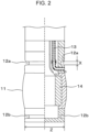
- Fig. 2 illustrates a partial section of the configuration of the distal end portion 3c to which a balloon is to be attached, the distal end portion 3c being a part of the insertion section 3 of the ultrasonic endoscope illustrated in Fig. 1 .
- This distal end portion 3c has an ultrasonic transmission-reception section 11 and is provided with bead-portion attachment grooves 12a and 12b to which a balloon is to be attached to cover the ultrasonic transmission-reception section.
- the distal end portion 3c has a pipe line 13 through which a liquid flows, the liquid filling a balloon interior space formed as a result of attachment of the balloon.
- the cross sections of the distal end portion taken along the bead-portion attachment grooves 12a and 12b are usually each a surface perpendicular to the central axis of the distal end portion 3c.
- the ultrasonic transducer 14 that performs conversion between electrical signals and ultrasonic waves is disposed in the ultrasonic transmission-reception section 11.
- the ultrasonic transducer 14 may have, for example, a radial scanning form in which a plurality of elements are arranged around the central axis of the columnar insertion section 3 in the circumferential direction.
- a width of each of the bead-portion attachment grooves 12a and 12b illustrated in Fig. 2 is a "width X" specified in the present invention.
- an outer diameter of a part of the groove, the part being surrounded by a top of the wall surface of the groove, (Z in Fig. 2 ) is an "outer diameter Z" specified in the present invention.
- the "top of the wall surface of the groove” refers to a part where dropping starts from the surface of the distal end portion 3c toward the bottom of a bead-portion attachment groove in order to form the bead-portion attachment groove, as illustrated in Fig. 2 .
- the width X means a distance between two side faces of a bead-portion attachment groove in a part where the two side faces are formed to be parallel to each other.
- a bead portion of a balloon is fitted in at least the part where the two side faces of the bead-portion attachment groove are formed to be parallel to each other.
- a cross section of the distal end portion 3c usually has a circular shape. Accordingly, a part of the bead-portion attachment groove, the part being surrounded by the top of the wall surface of the bead-portion attachment groove, (cross section of the distal end portion 3c taken along the top of the wall surface of the bead-portion attachment groove) also usually has a circular shape.
- the "outer diameter Z” means an equivalent circle diameter.
- This "equivalent circle diameter” means a diameter of a perfect circle having the same area as the part of the bead-portion attachment groove, the part being surrounded by the top of the wall surface of the bead-portion attachment groove.
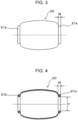
- Fig. 3 is an external view illustrating an example of the balloon according to the present invention
- Fig. 4 is a sectional view of the balloon.
- a balloon 20 is formed to have a substantially cylindrical shape and attached to the distal end portion 3c of the insertion section 3 by inserting the distal end portion 3c therein.
- the balloon 20 has thick annular bead portions 21a and 21b on both ends thereof and is fixed to the distal end portion 3c by attaching the bead portions 21a and 21b to the bead-portion attachment grooves 12a and 12b (refer to Fig. 2 ), respectively, in a watertight manner.
- Fig. 4 illustrates a "width W of a bead portion" and an “inner diameter Y of an opening of a balloon, the opening being surrounded by a bead portion” that are specified in the present invention.
- the bead portion is inserted into a part where two side faces are formed to be parallel to each other in a bead-portion attachment groove provided in the endoscope insertion section.
- a maximum width of the bead portion in a direction perpendicular to these two side faces is the width W of the bead portion.
- the inner diameter Y means an inner diameter of an opening of the balloon, the opening being surrounded by the bead portion, in a state where the balloon is freestanding in a cylindrical shape (which means a state where the balloon is allowed to stand such that the central axis direction of the hole of the balloon corresponds to a lateral direction, hereinafter, the same).
- an equivalent circle diameter is defined as the inner diameter Y.
- This "equivalent circle diameter” means a diameter of a perfect circle having the same area as the opening of the balloon, the opening being surrounded by the bead portion.
- Fig. 5 is a partial sectional view illustrating a state in which a balloon 20 is attached to a distal end portion 3c of an ultrasonic endoscope.
- Bead portions 21a and 21b provided on both ends of the balloon 20 are respectively inserted into bead-portion attachment grooves 12a and 12b that are provided in the distal end portion 3c having an ultrasonic transmission-reception section and attached to the bead-portion attachment grooves 12a and 12b in a watertight manner to provide a state in which a balloon interior space 20A can be filled with a liquid such as water through a pipe line 13.
- the balloon according to the present invention is formed of a synthetic elastomer. Specifically, the material for forming the balloon does not include natural rubber. Accordingly, the risk of developing the latex allergy caused by natural rubber can be reduced.
- the balloon according to the present invention and an endoscope insertion section to which the balloon is to be attached satisfy the following relations (a1) and (b1).
- the (a1) and (b1) above are relations between the balloon before the attachment to the endoscope insertion section (balloon in the unused state) and the ultrasonic endoscope insertion section (distal end portion) to which this balloon is to be attached.
- the (a1) and (b1) above are relations between a bead portion at one end of the balloon and a bead-portion attachment groove of the distal end portion 3c in which the bead portion is to be inserted, and relations between a bead portion at the other end of the balloon and another bead-portion attachment groove of the distal end portion 3c in which the bead portion is to be inserted.
- the above description means that the (a1) and (b1) above are satisfied in the relation between each of the bead portions and a bead-portion attachment groove corresponding to the bead portion.
- the width W of the bead portion is not uniform and there is variation in the width W, the relation between the width W of all the parts of the bead portion at the one end (or the bead portion at the other end) and the width X of the attachment groove of this bead portion satisfies the (a1) above.
- the width W of the bead portion is not uniform, and in a bead-portion attachment groove in which this bead portion is to be inserted, there is also variation in the width X of the groove, the width W of all the parts of the bead portion at the one end (or the bead portion at the other end) and the groove width X in all the parts of the bead-portion attachment groove in which this bead portion is to be inserted satisfy the (a1) above.
- the unit of the width W is the same as the unit of the width X (for example, each of the units is mm), and the unit of the inner diameter Y is also the same as the unit of the outer diameter Z (for example, each of the units is mm).
- the relation between the width W of the bead portion and the width X of the bead-portion attachment groove preferably satisfies 1.6 ⁇ W/X ⁇ 2.4, more preferably satisfies 1.65 ⁇ W/X ⁇ 2.3, and still more preferably satisfies 1.7 ⁇ W/X ⁇ 2.3.
- the dimension of the width W of the bead portion of the balloon is not particularly limited as long as the relation with the width X of the bead-portion attachment groove satisfies the above, and is preferably, for example, 0.5 to 3 mm, also preferably 1 to 2.5 mm, and more preferably 1.5 to 2.0 mm. As in the above case, if there is variation in the width of the bead portion of the balloon, the width of all the parts of the bead portion of the balloon preferably falls within the above preferred range.
- the dimension of the inner diameter Y of the opening of the balloon, the opening being surrounded by the bead portion is not particularly limited as long as the relation with the outer diameter Z of the part of the bead-portion attachment groove in the ultrasonic endoscope insertion section, the part being surrounded by the top of the wall surface of the bead-portion attachment groove, satisfies the above, and is preferably, for example, 1 to 8 mm, also preferably 2.5 to 6.5 mm, and more preferably 3.5 to 5.5 mm.
- the length of the balloon according to the present invention is appropriately determined depending on the purpose.
- the length from a bead portion at one end to a bead portion at the other end may be 10 to 100 mm, preferably 10 to 50 mm, and more preferably 20 to 40 mm.
- the length of the balloon in the central axis direction is preferably longer than the distance between the two bead-portion attachment grooves.
- the relation of the (b1) above preferably satisfies 0.37 ⁇ Y/Z ⁇ 0.55, more preferably satisfies 0.38 ⁇ Y/Z ⁇ 0.55, and still more preferably satisfies 0.40 ⁇ Y/Z ⁇ 0.55.
- Any synthetic polymer that exhibits rubber elasticity at room temperature (25°C) can be used as the synthetic elastomer for forming the balloon without particular limitation.
- vulcanized rubber, rubber-like elastic materials, and thermoplastic elastomers can be widely used.
- the synthetic elastomer used to form the balloon according to the present invention is preferably at least one of a styrene-based elastomer, an olefin-based elastomer, a vinyl chloride-based elastomer, a polyester-based elastomer, a polyurethane-based elastomer, a polyamide-based elastomer, a silicone-based elastomer, or a fluorine-based elastomer.
- Preferred examples of these elastomers will be described below; however, the present invention is not limited to these embodiments.
- the styrene-based elastomer is an elastomer whose hard segment has a polystyrene structure.
- examples of the styrene-based elastomer include styrene-butadiene block copolymers (SBR), hydrogenated styrene-butadiene block copolymers (SEB, styrene-ethylene/butylene block copolymers), styrene-butadiene-styrene block copolymers (SBS), hydrogenated styrene-butadiene-styrene block copolymers (SEBS, styrene-ethylene/butylene-styrene block copolymers), styrene-isoprene block copolymers (SIR), hydrogenated styrene-isoprene block copolymers (SEP, styrene-ethylene/propylene block copolymers
- the olefin-based elastomer is a crosslinked or non-crosslinked elastomer having a polyolefin structure.
- the olefin-based elastomer include ethylene-propylene copolymers, ethylene-1-butene copolymers, ethylene- ⁇ -olefin copolymers, propylene-1-butene copolymers, propylene- ⁇ -olefin copolymers, 1-butene- ⁇ -olefin copolymers, propylene-1-butene-ethylene copolymers, propylene- ⁇ -olefin-ethylene copolymers, propylene- ⁇ -olefin-1-butene copolymers, 1-butene- ⁇ -olefin-ethylene copolymers, isoprene rubber (IR), cis-1,4-polybutadiene (BR), chloroprene rubber (CR), butyl rubber (IIR), elastomers in which
- the vinyl chloride-based elastomer is an elastomer whose hard segment has a polyvinyl chloride structure.
- Examples of the vinyl chloride-based elastomer include polyvinyl chloride having a high degree of polymerization. Examples thereof further include an elastomer obtained by using a partially crosslinked polyvinyl chloride in which a crosslinked part functions as a hard segment and a linear part functions as a soft segment.
- One or two or more of vinyl chloride-based elastomers can be used to form the balloon according to the present invention.
- the polyester-based elastomer is an elastomer whose hard segment has a polyester structure.
- examples thereof that can be used include block copolymers having a high-melting-point polyester segment (hard segment) and a low-melting-point polymer segment (soft segment) having a molecular weight of about 400 to 6,000 and described in, for example, JP1999-92636A ( JP-H11-92636A ).
- An example of the high-melting-point polyester segment is a polybutylene terephthalate (PBT).
- An example of the low-melting-point polymer segment is an amorphous polyether having a glass transition temperature of -70°C, e.g., polytetramethylene ether glycol (PTMG).
- polyester-based elastomers can be used to form the balloon according to the present invention.
- the polyurethane-based elastomer is an elastomer whose hard segment has a polyurethane structure.
- An example of the polyurethane-based elastomer is an elastomer including structural units of a hard segment formed from a low-molecular-weight glycol and a diisocyanate and a soft segment formed from a high-molecular-weight (long-chain) diol and a diisocyanate.
- high-molecular-weight (long-chain) diol examples include polypropylene glycol, polytetramethylene oxide, poly(1,4-butylene adipate), poly(ethylene-1,4-butylene adipate), polycaprolactone, poly(1,6-hexylene carbonate), and poly(1,6-hexylene/neopentylene adipate).
- the high-molecular-weight (long-chain) diol preferably has a number-average molecular weight of 500 or more and less than 10,000.
- a short-chain diol such as ethylene glycol, propylene glycol, 1,4-butane diol, or bisphenol A can be used.
- the short-chain diol preferably has a number-average molecular weight of 48 or more and less than 500.
- One or two or more of polyurethane-based elastomers can be used to form the balloon according to the present invention.
- the polyamide-based elastomer is an elastomer whose hard segment has a polyamide structure.
- Examples thereof include multiblock copolymers including a hard segment formed from a polyamide and a soft segment formed from a polyether or a polyester.
- Examples of the hard segment include polyamides 6, 66, 610, 11, and 12.
- Examples of the polyether in the soft segment include polyethylene glycol, diol poly(oxytetramethylene) glycol, and poly(oxypropylene) glycol.
- Examples of the polyester in the soft segment include poly(ethylene adipate)glycol and poly(butylene-1,4-adipate)glycol.
- One or two or more of polyamide-based elastomers can be used to form the balloon according to the present invention.
- the silicone-based elastomer is an elastomer having an organopolysiloxane structure.
- the silicone-based elastomer is an elastomer produced by introducing a crosslinked structure into an organopolysiloxane.
- polydimethylsiloxane-based, polymethylphenylsiloxane-based, and polydiphenylsiloxane-based elastomers are known.
- Specific examples of a commercially available silicone-based elastomer include KE series (manufactured by Shin-Etsu Chemical Co., Ltd.) and SE series, CY series, and SH series (all of which are manufactured by Dow Corning Toray Silicone Co., Ltd.).
- One or two or more of silicone-based elastomers can be used to form the balloon according to the present invention.
- the fluorine-based elastomer is an elastomer whose hard segment is formed from a fluororesin.
- the fluorine-based elastomer include tetrafluoroethylene-ethylene copolymers, tetrafluoroethylene-propylene copolymers, chlorotrifluoroethylene-ethylene copolymers, polyvinylidene fluoride, polyvinyl fluoride, vinylidene fluoride-hexafluoropropylene copolymers, tetrafluoroethylene-vinylidene fluoride-hexafluoropropylene copolymers, tetrafluoroethylene-vinylidene fluoride-perfluoroalkyl vinyl ether copolymers, tetrafluoroethylene-vinylidene fluoride-propylene copolymers, and tetrafluoroethylene-vinylidene fluoride-hexafluoropropylene copoly
- One or two or more of fluorine-based elastomers can be used to form the balloon according to the present invention.
- the balloon according to the present invention preferably includes at least one olefin-based elastomer, and in particular, preferably includes isoprene rubber.
- the balloon according to the present invention is more preferably formed of at least one olefin-based elastomer and still more preferably formed of isoprene rubber.
- the balloon according to the present invention preferably has a coating layer on at least an outer surface thereof.
- This coating layer can reduce adhesion between balloons during, for example, shipping and storage of the balloons.
- This coating layer is preferably formed of a synthetic elastomer.
- the above synthetic elastomers that can be used to form the balloon can be used as the synthetic elastomers that can be used to form the coating layer.
- the synthetic elastomer used to form the balloon and the synthetic elastomer used to form the coating layer are preferably different types of synthetic elastomers.
- the synthetic elastomer used is preferably at least one of a polyurethane-based elastomer, a silicone-based elastomer, or a fluorine-based elastomer.
- the balloon according to the present invention can be produced by a common method except that the width W of each bead portion of the balloon and the inner diameter Y of the opening of the balloon, the opening being surrounded by the bead portion, satisfy the specific relations described above together with the ultrasonic endoscope insertion section (distal end portion) to which the balloon is to be attached.
- a metallic mold having a desired size and shape is prepared, and the metallic mold is immersed in a dispersion liquid or solution of a polymer used for balloon formation to cause the polymer to adhere to the surface of the metallic mold.
- the adhering polymer is then dried, and the polymer adhering to the metallic mold is rolled up from an end such that the width of each bead portion and the inner diameter of the opening surrounded by the bead portion have desired dimensions.
- the polymer is removed from the metallic mold, optionally washed with, for example, water, and dried or performing a crosslinking reaction.
- the width of the bead portion of the balloon and the inner diameter of the opening surrounded by the bead portion can be determined by observation with a microscope or the like.
- extrusion molding or blow molding can also provide a balloon having a desired width of each bead portion and a desired inner diameter of the opening surrounded by the bead portion.
- the coating layer of the balloon can be formed by a common method except that the balloon to be subjected to coating is the balloon according to the present invention.
- the coating layer can be formed by immersing the balloon in a dispersion liquid, solution, or the like including a coating material or spraying a dispersion liquid, solution, or the like including a coating material on the balloon, and optionally subjecting the balloon to drying treatment or the like.
- An ultrasonic endoscope according to the present invention is an ultrasonic endoscope including the balloon according to the present invention.
- the configuration of the balloon included in the ultrasonic endoscope according to the present invention and the configuration other than that of the balloon (that is, the configuration of the ultrasonic endoscope main body) are as described above.
- the ultrasonic endoscope according to the present invention may be in a state where the balloon is attached.
- an ultrasonic endoscope before the attachment of the balloon and the balloon may be separated from each other. That is, an embodiment in which an ultrasonic endoscope before the attachment of a balloon and an unused balloon are separated from each other (a set of an ultrasonic endoscope and a balloon) is also encompassed by the ultrasonic endoscope according to the present invention.
- the method for attaching the balloon to the insertion section (distal end portion) of the ultrasonic endoscope is not particularly limited.
- the central axis of a tubular holding device and the central axis of the hole of the balloon are caused to substantially coincide with each other, and the balloon is placed in the hole of the holding device.
- the expanded bead portion is folded back to the outer surface of the holding device so that the bead portion is fixed to a groove provided in the outer surface of the holding device, thus providing a state in which one end of the hole of the balloon is expanded to the size of the tube of the holding device.
- the insertion section (distal end portion) of the ultrasonic endoscope is inserted into the hole of the expanded balloon.
- the bead portion fixed to the groove in the outer surface of the holding device is moved to a bead-portion attachment groove (of the two bead-portion attachment grooves provided in the distal end portion, the bead-portion attachment groove provided on the angle portion side) of the endoscope insertion section (distal end portion).
- the one end of the bead portion is fixed to the endoscope insertion section.
- the holding device is removed, and water is supplied to fill the interior of the balloon with water.
- the other bead portion is expanded by the hand, and the bead portion expanded by the hand is fixed to the other bead-portion attachment groove of the endoscope insertion section while preventing air from entering the balloon interior space.
- the balloon can be attached to the insertion section (distal end portion) of the ultrasonic endoscope.
- the present invention provides a method for producing an ultrasonic endoscope with a balloon described below.
- a method for producing an ultrasonic endoscope with a balloon attached to cover an ultrasonic transmission-reception section of an endoscope insertion section including providing a balloon and an ultrasonic endoscope that satisfy relations (a) and (b) below, and attaching the balloon to the ultrasonic endoscope:
- a balloon having the shape illustrated in Figs. 3 and 4 was produced.
- a metallic mold having a shape corresponding to the shape of the balloon illustrated in Figs. 3 and 4 was immersed in a polyisoprene latex dispersion liquid (including a vulcanizing agent) to cause a polyisoprene latex to adhere to the surface of the metallic mold. Subsequently, the adhering polyisoprene latex was dried on the metallic mold. A balloon end was cut, and polyisoprene adhering to the metallic mold was rolled up from the end such that the width of a bead portion and the inner diameter of an opening surrounded by the bead portion were as described in Table 1, thus forming a bean portion. Two bead portions on both ends of the balloon had the same shape and the same size.
- each of the bead portions had a circular shape as illustrated in Fig. 4 .
- the polymer was removed from the metallic mold, washed with water, and vulcanized at 140°C.
- a balloon formed of isoprene rubber and shown in Table 1 was produced.
- the balloon produced as described above had, in the freestanding state, a length of 25 mm in the central axis direction of the balloon.
- the elastomer for forming a balloon was changed as shown in Table 1, and balloons shown in Table 1 were produced.
- the balloons of Examples 10 to 19 each had, in the freestanding state, a length of 25 mm in the central axis direction of the balloon.
- the temperature of the elastomer for forming a balloon was increased to a temperature at which the elastomer had fluidity high enough for molding, and the elastomer was injection-molded in a metallic mold to produce a balloon.
- the elastomer for forming a balloon was blow-molded to produce a balloon.
- the elastomer for forming a balloon was dissolved in a solvent in which the elastomer is soluble, a metallic mold was immersed in the resulting solution and pulled up, and the solvent was then dried to produce a balloon.
- a scope having the shape illustrated in Fig. 2 was used as a distal end portion of an endoscope insertion section to which the balloon was to be attached.
- the widths X of bead-portion attachment grooves are each 1 mm
- the outer diameters Z of parts annularly surrounded by the tops of wall surfaces of the two bead-portion attachment grooves are each 10.7 mm
- the distance between the two bead-portion attachment grooves is 17.8 mm.
- the balloon was attached to the above scope, and water was supplied through the pipe line to the balloon interior space at a flow rate of 100 mL/min. The time taken from the start of this water supply to breaking of the balloon was measured.
- a balloon having the same shape and size as the balloon used in the test was prepared by using natural rubber and used as a reference sample. The balloon strength was evaluated on the basis of evaluation criteria described below.
- breaking of the balloon had not yet occurred, and it was not until after the water supply in the Test Example that breaking occurred. In each of the cases, the breaking of the balloon did not occur in a bead portion but occurred in the vicinity of a bead portion.
- the balloons satisfying the requirements of the present invention in terms of the relations with the endoscope insertion section each could be sufficiently fixed to the endoscope insertion section, and these balloons were resistant to the water pressure and unlikely to break (Examples 1 to 19).
- a balloon was produced as in Example 3.
- the balloon was immersed in a solution prepared by dissolving an elastomer for coating shown in the table below.
- the balloon was then dried.
- the outer surface of the balloon was coated with the elastomer different from the material for forming the balloon.
- Table 2 shows the results.
- the abbreviations in Table 2 have the same meaning as those in Table 1.
- Table 2 Type of elastomer for forming balloon Type of elastomer for forming coating layer Occurrence or nonoccurrence of adhesion between balloons Example 3 IR None Occur Example 20 IR Si Not occur Example 21 IR F Not occur Example 22 IR PUR Not occur The abbreviations are the same as those in Table 1.
- adhesion between balloons can be prevented by providing a coating layer on a balloon formed of a synthetic elastomer. Accordingly, balloons that are easily handled even during storage and distribution can be provided by subjecting the balloons to coating treatment.
Landscapes
- Health & Medical Sciences (AREA)
- Life Sciences & Earth Sciences (AREA)
- Surgery (AREA)
- Engineering & Computer Science (AREA)
- Medical Informatics (AREA)
- Molecular Biology (AREA)
- Radiology & Medical Imaging (AREA)
- Nuclear Medicine, Radiotherapy & Molecular Imaging (AREA)
- Biomedical Technology (AREA)
- Heart & Thoracic Surgery (AREA)
- Physics & Mathematics (AREA)
- Pathology (AREA)
- Biophysics (AREA)
- Animal Behavior & Ethology (AREA)
- General Health & Medical Sciences (AREA)
- Public Health (AREA)
- Veterinary Medicine (AREA)
- Optics & Photonics (AREA)
- Manufacturing & Machinery (AREA)
- Ultra Sonic Daignosis Equipment (AREA)
Claims (9)
- Ultraschallendoskop (2), umfassend einen Ballon (20), wobei der Ballon (20) ein synthetisches Elastomer umfasst,dadurch gekennzeichnet, dass ein Verhältnis zwischen einer Breite W eines Wulstabschnitts (21a, 21b) des Ballons (20) und einer Breite X einer Wulstabschnitt-Befestigungsnut (12a, 12b), die in dem Ultraschallendoskop- (2) - Einführungsabschnitt (3) bereitgestellt ist, um den Ballon (20) zu fixieren, 1,1 <_ W/X <_ 2,5 beträgt, und dassein Verhältnis zwischen einem Innendurchmesser Y einer Öffnung des Ballons (20), wobei die Öffnung von dem Wulstabschnitt (21a, 21b) umgeben ist, und einem Außendurchmesser Z eines Teils der Wulstabschnitt-Befestigungsnut (12a, 12b) in dem Ultraschallendoskop- (2) -Einführungsabschnitt (3), wobei der Teil von einer Oberseite einer Wandfläche der Wulstabschnitt-Befestigungsnut (12a, 12b) umgeben ist, 0,30 ≤ Y/Z ≤ 0,55 beträgt.
- Ultraschallendoskop (2) nach Anspruch 1, wobei das synthetische Elastomer mindestens eines aus einem Elastomer auf Styrolbasis, einem Elastomer auf Olefinbasis, einem Elastomer auf Vinylchloridbasis, einem Elastomer auf Polyesterbasis, einem Elastomer auf Polyurethanbasis, einem Elastomer auf Polyamidbasis, einem Elastomer auf Silikonbasis oder einem Elastomer auf Fluorbasis ist.
- Ultraschallendoskop (2) nach Anspruch 1 oder 2, wobei das synthetische Elastomer mindestens ein Elastomer auf Olefinbasis einschließt.
- Ultraschallendoskop (2) nach einem der Ansprüche 1 bis 3, wobei das synthetische Elastomer Isoprenkautschuk einschließt.
- Ultraschallendoskop (2) nach einem der Ansprüche 1 bis 4, wobei der Ballon (20) zumindest auf einer seiner Außenflächen eine Beschichtung aufweist.
- Ultraschallendoskop (2) nach Anspruch 5, wobei die Beschichtung aus einem synthetischen Elastomer gebildet ist, das sich von dem synthetischen Elastomer, das den Ballon (20) bildet, unterscheidet.
- Ultraschallendoskop (2) nach Anspruch 6, wobei das synthetische Elastomer, das zum Bilden der Beschichtung verwendet wird, mindestens eines aus einem Elastomer auf Styrolbasis, einem Elastomer auf Olefinbasis, einem Elastomer auf Vinylchloridbasis, einem Elastomer auf Polyesterbasis, einem Elastomer auf Polyurethanbasis, einem Elastomer auf Polyamidbasis, einem Elastomer auf Silikonbasis oder einem Elastomer auf Fluorbasis ist.
- Ultraschallendoskop (2) nach Anspruch 6 oder 7, wobei das synthetische Elastomer, das zum Bilden der Beschichtung verwendet wird, mindestens ein Elastomer auf Polyurethanbasis, ein Elastomer auf Silikonbasis oder ein Elastomer auf Fluorbasis ist.
- Verfahren zur Herstellung eines Ultraschallendoskops (2) mit einem Ballon (20), der so angebracht ist, dass er einen Ultraschall-Sende-Empfangsabschnitt eines Endoskop- (2) -Einführungsabschnitts (3) abdeckt, wobei das Verfahren folgendes umfasst:Bereitstellen eines Ballons (20) und eines Ultraschallendoskops (2), die die folgenden Beziehungen (a) und (b) erfüllen; undAnbringen des Ballons (20) an einem Einführungsabschnitt (3) des Ultraschallendoskops (2):(a) ein Verhältnis zwischen einem Außendurchmesser W eines Wulstabschnitts (21a, 21b) des Ballons (20) und einer Breite X einer Wulstabschnitt-Befestigungsnut (12a, 12b), die in dem Einführungsabschnitt (3) des Ultraschallendoskops (2) bereitgestellt ist, um den Ballon (20) zu fixieren, 1,1 ≤ W/X ≤ 2,5 beträgt; und(b) ein Verhältnis zwischen einem Innendurchmesser Y einer Öffnung des Ballons (20), wobei die Öffnung von dem Wulstabschnitt (21a, 21b) umgeben ist, und einem Außendurchmesser Z eines Teils der Wulstabschnitt-Befestigungsnut (12a, 12b) in dem Einführungsabschnitt (3) des Ultraschallendoskops (2), wobei der Teil von einer Oberseite einer Wandfläche der Wulstabschnitt-Befestigungsnut (12a, 12b) umgeben ist, 0,30 ≤ Y/Z ≤ 0,55. beträgt.
Applications Claiming Priority (2)
| Application Number | Priority Date | Filing Date | Title |
|---|---|---|---|
| JP2018158204 | 2018-08-27 | ||
| PCT/JP2019/029573 WO2020044905A1 (ja) | 2018-08-27 | 2019-07-29 | 超音波内視鏡用バルーン、これを備えた超音波内視鏡及びその製造方法 |
Publications (3)
| Publication Number | Publication Date |
|---|---|
| EP3845131A1 EP3845131A1 (de) | 2021-07-07 |
| EP3845131A4 EP3845131A4 (de) | 2021-10-20 |
| EP3845131B1 true EP3845131B1 (de) | 2024-04-24 |
Family
ID=69643620
Family Applications (1)
| Application Number | Title | Priority Date | Filing Date |
|---|---|---|---|
| EP19853845.6A Active EP3845131B1 (de) | 2018-08-27 | 2019-07-29 | Ultraschallendoskopballon, ultraschallendoskop damit und herstellungsverfahren dafür |
Country Status (5)
| Country | Link |
|---|---|
| US (1) | US20210177243A1 (de) |
| EP (1) | EP3845131B1 (de) |
| JP (1) | JP6988002B2 (de) |
| CN (1) | CN112638276A (de) |
| WO (1) | WO2020044905A1 (de) |
Families Citing this family (1)
| Publication number | Priority date | Publication date | Assignee | Title |
|---|---|---|---|---|
| USD855803S1 (en) * | 2015-07-30 | 2019-08-06 | Fujifilm Corporation | Endoscope |
Family Cites Families (15)
| Publication number | Priority date | Publication date | Assignee | Title |
|---|---|---|---|---|
| JP2601022Y2 (ja) * | 1992-07-14 | 1999-11-02 | 旭光学工業株式会社 | 超音波診断装置 |
| CA2114988A1 (en) * | 1993-02-05 | 1994-08-06 | Matthew O'boyle | Ultrasonic angioplasty balloon catheter |
| JP3947943B2 (ja) | 1997-09-22 | 2007-07-25 | 東洋紡績株式会社 | 熱可塑性ポリエステルエラストマー樹脂組成物及びその製造法 |
| JP4588840B2 (ja) * | 2000-05-15 | 2010-12-01 | オリンパス株式会社 | 超音波プローブ及び超音波プローブシステム |
| US20050228452A1 (en) * | 2004-02-11 | 2005-10-13 | Mourlas Nicholas J | Steerable catheters and methods for using them |
| JP4618410B2 (ja) * | 2004-07-06 | 2011-01-26 | 富士フイルム株式会社 | 超音波内視鏡 |
| JP4875450B2 (ja) * | 2006-10-17 | 2012-02-15 | オリンパスメディカルシステムズ株式会社 | 内視鏡、内視鏡用フードおよび内視鏡装置 |
| JP2008200380A (ja) * | 2007-02-22 | 2008-09-04 | Live Aid:Kk | 超音波計測による骨波形の評価方法及びその装置並びにその評価プログラムを記録した記録媒体 |
| JP2010082337A (ja) * | 2008-10-01 | 2010-04-15 | Hitachi Medical Corp | 超音波診断装置 |
| JP5669996B1 (ja) * | 2013-08-22 | 2015-02-18 | オリンパスメディカルシステムズ株式会社 | 超音波内視鏡及び内視鏡用超音波バルーン |
| WO2016038926A1 (ja) * | 2014-09-09 | 2016-03-17 | オリンパス株式会社 | 超音波振動子アレイ |
| JP6616681B2 (ja) * | 2015-12-22 | 2019-12-04 | オリンパス株式会社 | バルーン、及びバルーンの取り付け方法 |
| EP3424435A4 (de) * | 2016-03-03 | 2019-11-27 | Olympus Corporation | Ultraschallendoskop |
| CN109310283A (zh) * | 2016-04-19 | 2019-02-05 | 波士顿科学国际有限公司 | 包括加强元件的球囊导管可视化装置 |
| JP2018158204A (ja) | 2018-07-17 | 2018-10-11 | 株式会社大一商会 | 遊技機 |
-
2019
- 2019-07-29 JP JP2020540166A patent/JP6988002B2/ja active Active
- 2019-07-29 EP EP19853845.6A patent/EP3845131B1/de active Active
- 2019-07-29 WO PCT/JP2019/029573 patent/WO2020044905A1/ja unknown
- 2019-07-29 CN CN201980055985.9A patent/CN112638276A/zh active Pending
-
2021
- 2021-02-17 US US17/177,768 patent/US20210177243A1/en active Pending
Also Published As
| Publication number | Publication date |
|---|---|
| CN112638276A (zh) | 2021-04-09 |
| EP3845131A4 (de) | 2021-10-20 |
| EP3845131A1 (de) | 2021-07-07 |
| WO2020044905A1 (ja) | 2020-03-05 |
| US20210177243A1 (en) | 2021-06-17 |
| JPWO2020044905A1 (ja) | 2021-03-11 |
| JP6988002B2 (ja) | 2022-01-05 |
Similar Documents
| Publication | Publication Date | Title |
|---|---|---|
| US8186349B2 (en) | Tracheostomy tube | |
| US10286115B2 (en) | Multilayer medical balloon | |
| CN102204806B (zh) | 内窥镜用挠性管及其制造方法 | |
| US20070265565A1 (en) | Mesh-Reinforced Catheter Balloons and Methods for Making the Same | |
| US20210177243A1 (en) | Balloon for ultrasonic endoscope, ultrasonic endoscope including the same, and method for producing ultrasonic endoscope | |
| US20100300448A1 (en) | Tracheostomy Tube | |
| JPS6244498B2 (de) | ||
| WO2006121163A1 (ja) | 内視鏡可撓管 | |
| JP2010136834A (ja) | 内視鏡軟性部及び内視鏡 | |
| JP2016533218A (ja) | 耐高圧引裂性バルーン | |
| JP2005021243A (ja) | 内視鏡用可撓管および内視鏡 | |
| US20050113856A1 (en) | Method of joining materials | |
| JP2005027717A (ja) | 内視鏡用可撓管および内視鏡 | |
| JP2000079092A (ja) | 内視鏡装置 | |
| JP2005021242A (ja) | 内視鏡用可撓管および内視鏡 | |
| JP2010110444A (ja) | 内視鏡の可撓管 | |
| JP5935208B2 (ja) | ニトリルゴムとブチルゴムとの架橋接着積層体 | |
| US20200297449A1 (en) | Cover for an ultrasound probe | |
| JP5455458B2 (ja) | 内視鏡の可撓管の製造方法 | |
| JP2001008887A (ja) | 内視鏡のアングル部 | |
| JP2002065590A (ja) | 内視鏡用可撓管 | |
| US20190255224A1 (en) | Medical balloon, method for manufacturing medical balloon, and balloon catheter | |
| JP2022141095A (ja) | カテーテル | |
| CN116018539A (zh) | 内窥镜用挠性管、内窥镜型医疗器材、及它们的制造方法 | |
| JP2002143085A (ja) | 内視鏡用可撓管 |
Legal Events
| Date | Code | Title | Description |
|---|---|---|---|
| STAA | Information on the status of an ep patent application or granted ep patent |
Free format text: STATUS: THE INTERNATIONAL PUBLICATION HAS BEEN MADE |
|
| STAA | Information on the status of an ep patent application or granted ep patent |
Free format text: STATUS: THE INTERNATIONAL PUBLICATION HAS BEEN MADE |
|
| STAA | Information on the status of an ep patent application or granted ep patent |
Free format text: STATUS: REQUEST FOR EXAMINATION WAS MADE |
|
| PUAI | Public reference made under article 153(3) epc to a published international application that has entered the european phase |
Free format text: ORIGINAL CODE: 0009012 |
|
| 17P | Request for examination filed |
Effective date: 20210217 |
|
| AK | Designated contracting states |
Kind code of ref document: A1 Designated state(s): AL AT BE BG CH CY CZ DE DK EE ES FI FR GB GR HR HU IE IS IT LI LT LU LV MC MK MT NL NO PL PT RO RS SE SI SK SM TR |
|
| A4 | Supplementary search report drawn up and despatched |
Effective date: 20210916 |
|
| RIC1 | Information provided on ipc code assigned before grant |
Ipc: A61B 8/00 20060101ALI20210910BHEP Ipc: A61B 1/00 20060101ALI20210910BHEP Ipc: A61B 8/12 20060101AFI20210910BHEP |
|
| DAV | Request for validation of the european patent (deleted) | ||
| DAX | Request for extension of the european patent (deleted) | ||
| STAA | Information on the status of an ep patent application or granted ep patent |
Free format text: STATUS: EXAMINATION IS IN PROGRESS |
|
| 17Q | First examination report despatched |
Effective date: 20230419 |
|
| GRAP | Despatch of communication of intention to grant a patent |
Free format text: ORIGINAL CODE: EPIDOSNIGR1 |
|
| STAA | Information on the status of an ep patent application or granted ep patent |
Free format text: STATUS: GRANT OF PATENT IS INTENDED |
|
| INTG | Intention to grant announced |
Effective date: 20231219 |
|
| GRAS | Grant fee paid |
Free format text: ORIGINAL CODE: EPIDOSNIGR3 |
|
| GRAA | (expected) grant |
Free format text: ORIGINAL CODE: 0009210 |
|
| STAA | Information on the status of an ep patent application or granted ep patent |
Free format text: STATUS: THE PATENT HAS BEEN GRANTED |
|
| AK | Designated contracting states |
Kind code of ref document: B1 Designated state(s): AL AT BE BG CH CY CZ DE DK EE ES FI FR GB GR HR HU IE IS IT LI LT LU LV MC MK MT NL NO PL PT RO RS SE SI SK SM TR |
|
| REG | Reference to a national code |
Ref country code: GB Ref legal event code: FG4D |
|
| REG | Reference to a national code |
Ref country code: CH Ref legal event code: EP |
|
| REG | Reference to a national code |
Ref country code: DE Ref legal event code: R096 Ref document number: 602019051067 Country of ref document: DE |
|
| REG | Reference to a national code |
Ref country code: IE Ref legal event code: FG4D |