EP3842769B1 - Wägezelle und wägezellenwaage - Google Patents
Wägezelle und wägezellenwaage Download PDFInfo
- Publication number
- EP3842769B1 EP3842769B1 EP19852531.3A EP19852531A EP3842769B1 EP 3842769 B1 EP3842769 B1 EP 3842769B1 EP 19852531 A EP19852531 A EP 19852531A EP 3842769 B1 EP3842769 B1 EP 3842769B1
- Authority
- EP
- European Patent Office
- Prior art keywords
- load cell
- stopper
- tip
- cell unit
- weighting
- Prior art date
- Legal status (The legal status is an assumption and is not a legal conclusion. Google has not performed a legal analysis and makes no representation as to the accuracy of the status listed.)
- Active
Links
Images


Classifications
-
- G—PHYSICS
- G01—MEASURING; TESTING
- G01G—WEIGHING
- G01G21/00—Details of weighing apparatus
- G01G21/24—Guides or linkages for ensuring parallel motion of the weigh-pans
- G01G21/244—Guides or linkages for ensuring parallel motion of the weigh-pans combined with flexure-plate fulcrums
-
- G—PHYSICS
- G01—MEASURING; TESTING
- G01G—WEIGHING
- G01G23/00—Auxiliary devices for weighing apparatus
- G01G23/005—Means for preventing overload
-
- G—PHYSICS
- G01—MEASURING; TESTING
- G01G—WEIGHING
- G01G3/00—Weighing apparatus characterised by the use of elastically-deformable members, e.g. spring balances
- G01G3/12—Weighing apparatus characterised by the use of elastically-deformable members, e.g. spring balances wherein the weighing element is in the form of a solid body stressed by pressure or tension during weighing
- G01G3/14—Weighing apparatus characterised by the use of elastically-deformable members, e.g. spring balances wherein the weighing element is in the form of a solid body stressed by pressure or tension during weighing measuring variations of electrical resistance
- G01G3/1402—Special supports with preselected places to mount the resistance strain gauges; Mounting of supports
- G01G3/1412—Special supports with preselected places to mount the resistance strain gauges; Mounting of supports the supports being parallelogram shaped
-
- G—PHYSICS
- G01—MEASURING; TESTING
- G01L—MEASURING FORCE, STRESS, TORQUE, WORK, MECHANICAL POWER, MECHANICAL EFFICIENCY, OR FLUID PRESSURE
- G01L1/00—Measuring force or stress, in general
- G01L1/26—Auxiliary measures taken, or devices used, in connection with the measurement of force, e.g. for preventing influence of transverse components of force, for preventing overload
Definitions
- the present invention relates to a load cell and load cell scale.
- a resolution when using a load cell scale to measure the weight of a weighted object is limited by a gravimetric sensor, more specifically, limited by a measurement range (maximum weight) of a load cell configuring the gravimetric sensor.
- the gravimetric sensor In a general load cell scale, the gravimetric sensor has only one load cell. A tip end portion of the gravimetric sensor is connected to an upper beam thereof to receive a force from a weighing tray of the load cell scale, and a base end portion of the gravimetric sensor is connected to a lower beam thereof to be fixed to a base plate of the load cell scale.
- an electronic scale having a weighting of five kilograms (kg) generally has the resolution less than 1 gram (g) .
- the weighting thereof is generally suitable for weighting a weighted object of several hundred grams.
- the gravimetric sensor in a conventional load cell scale can only weight the weighted obj ect with a single resolution.
- Patent Document 1 a double-weighting electronic scale configured from two gravimetric sensors having different resolutions is disclosed.
- the electronic scale disclosed in Patent Document 1 in a case when a weighted object whose weight is less than a predetermined weight, the weighted object is only supported by the gravimetric sensor having a smaller weighting so as to measure the weight of the weighted object.
- the weighted object in a case when the weighted object whose weight is more than the predetermined weight, the weighted object is supported by both of the gravimetric sensors so as to measure the weight of the weighted object.
- Patent Document 1 Chinese Patent Application Publication No. 106124020A
- the gravimetric sensor whose weighting is larger is supported by a spring which does not have rigidity, for example, in a case when a 10 kg weighted object is placed on the weighting tray, the weighting process becomes unstable due to the vibration of the spring.
- a criterion for switching the two gravimetric sensors having different weightings is determined only by an elastic force of the spring, there is a possibility that the switching of the two gravimetric sensors is not correctly performed. Accordingly, there is a problem that according to the electronic scale disclosed in Patent Document 1, the weighting result may be incorrect and it is not suitable for being used in a commercial environment due to a short service life.
- the present invention is made in consideration of the foregoing circumstance, and an object of the present invention is to provide a load cell configured to be able to restrict the deformation occurring in the load cell even if in a case when a load exceeding the weighting is applied thereto, and a load cell scale having the load cell. Also, the present invention is made to achieve an obj ect to provide a load cell scale configured to have a plurality of load cells having different weightings so as to switch among the different weightings and perform the weighting of the weighted object correctly.
- the present invention is directed to a load cell scale as defined in the appended claims.
- the load cell scale includes a load cell part formed in a columnar shape, the load cell part having a upper surface extending along a longitudinal axis and a lateral surface intersecting with the upper surface, and a stopper part configured to restrict deformation occurring in the load cell due to a load exceeding a predetermined value and applied to the load cell, wherein the load cell part has a strain portion capable of elastically deforming and the strain portion penetrates the load cell part from the lateral surface in a short direction orthogonal to the longitudinal direction, and wherein the stopper portion is provided to be connected to the lateral surface of the load cell part.
- the stopper part is a plate-shaped member formed to extend along the longitudinal axis, and the stopper part has a fixing-end portion fixed to the lateral surface of the load cell and a free-end portion separating from the fixing-end portion along the longitudinal axis, the free-end portion being configured to restrict the elastic deformation of the load cell part due to the load in a state when the fixing-end portion is fixed to the lateral surface.
- the stopper part may have a first width at the fixing-end portion and a second width in a range where the strain portion is formed along the longitudinal axis, and the first width of the stopper part is larger than the second width of the stopper part.
- the fixing-end portion of the stopper part may have a third width between the first width and the second width.
- the load cell part may have a position-restriction member formed to extend from the lateral surface in the short direction
- the stopper part may have a position-restriction hole formed in the free-end portion and having a width suitable for the position-restriction member to enter, wherein when the load less than the predetermined value is applied to the load cell part, the position-restriction member may be at a position movable into the position-restriction hole, and when the load equal to or larger than the predetermined value is applied to the load cell part, the position-restriction member may be engaged with the position-restriction hole.
- the stopper part may have a position-restriction tank configured to restrict an operation of the free-end portion, and the free-end portion may be in the position-restriction tank in the height direction.
- An engaging hole for connecting the stopper part may be formed in the lateral surface of the load cell part, the stopper part may have an engaging member at the fixing-end portion that is capable of engaging with the engaging hole, and the stopper part may be connected to the lateral surface of the load cell part by engaging the engaging member with the engaging hole.
- the lateral surface of the load cell part may have a groove formed along the direction of the longitudinal axis and in a range where the strain portion is formed in the height direction orthogonal to the upper surface, and the stopper part may be disposed to be accommodated in the groove.
- the load cell scale may further have an intermediate member formed to be sandwiched between the load cell part and a portion where the stopper part is fixed to the lateral surface along the short direction.
- the load cell part may be configured by configuring a first load cell having a first weighting and a second load cell having a second weighting that is larger than the first weighting along the direction of the longitudinal axis or the height direction, the stopper part may have a first stopper and a second stopper corresponding to the first load cell and the second load cell respectively, and the fixing-end portion of the first stopper and the free-end portion of the second stopper is adjacent to each other.
- a first length of the first stopper along the direction of the longitudinal axis of the first stopper may be different from a second length of the second stopper along the direction of the longitudinal axis of the second stopper.
- the elastic deformation may occur in the first load cell and the free-end portion of the first stopper may move with respect to the first load cell, and when the load being larger than the first weighting and less than the second weighting is applied to the first load cell, the elastic deformation may occur in the second load cell and the free-end portion of the second stopper may move with respect to the second load cell in a state in which the first stopper and the first load cell are engaged with each other.
- the first load cell and the second load cell may have a first position-restriction member and a second position-restriction member respectively
- the first stopper and the second stopper may have a first position-restriction hole and a second position-restriction hole formed in the free-end portions of the first stopper and the second stopper and having widths suitable for the first position-restriction member and the second position-restriction member to enter respectively, when the load less than the first weighting is applied to the load cell part
- the first position-restriction member and the second position-restriction member may be movable in the first position-restriction hole and the second position-restriction hole respectively, when the load equal to or larger than the first weighting and less than the second weighting is applied to the load cell part
- the first position-restriction member may be engaged with the first position-restriction hole and the second position-restriction member may be movable in the second position-restriction hole, and
- the load cell scale may further include a protection member fixed to the first load cell, and when the load larger than the first weighting is applied, the first load cell and the protection member may operate simultaneously to prevent the deformation occurring in the first load cell.
- the second topper of the second load cell may have a third width between the first width and the second width in the fixing-end portion.
- the load cell disclosed in the above-described aspects even if in a case when the load exceeding the weighting is applied, it is possible to restrict the deformation occurring in the load. Also, according to the above-described aspects, in the load cell scale configured from the plurality of load cells having different weightings, it is possible to accurately switch the weightings and measure the weighting of the weighted object.
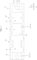
- FIG. 1 is a perspective view showing the load cell 10 according to the present embodiment.
- Fig. 2 is a front view showing the configuration of the load cell 10.
- Fig. 3 is a side view showing the configuration of the load cell. In the present embodiment, a direction along the Y-axis shown in Fig.
- a direction of a longitudinal axis of the load cell 10 a direction along the X-axis that is orthogonal to the direction along the Y-axis is defined as a short direction of the load cell 10, and a direction orthogonal to a plane defined by the X-axis and the Y-axis is defined as a height direction.
- an end portion at the left side of the load cell 10 along the direction along the Y-axis is defined as a tip end
- an end portion at the right side of the load cell 10 is defined as a base end.
- the load cell 10 has a columnar body 100 having a square pole shape formed to extend in the direction of the longitudinal axis (that is, in the direction of Y-axis) and a stopper member 200 connected to the columnar body 100.
- the columnar body 100 and the stopper member 200 of the load cell 10 are members having rigidity and being formed from various metal materials.
- the columnar body 100 is formed to extend in the direction of the longitudinal axis L (that is, in the direction of Y-axis).
- the columnar body 100 has an upper surface 101 formed to extend along the longitudinal axis L, a lateral surface 102 formed to be orthogonal to the upper surface 101, and an end surface 103 orthogonal to both of the upper surface 101 and the lateral surface 102.
- the upper surface 101 is formed in a plane defined by the X-axis and the Y-axis
- the lateral surface 102 is formed in a plane defined by the Y-axis and the Z-axis
- the end surface 103 is formed in a plane defined by the X-axis and the Z-axis.
- a penetration hole 151 is formed by cutting off part of the columnar body 100 inwardly from the lateral surface 102 along the short direction of the columnar body 100 (that is, along the direction of X-axis) .
- an internal circumferential surface of the penetration hole 151 in a case of viewing the penetration hole 151 formed in the columnar body 100 from the direction of X-axis, has a shape formed by arranging two substantial semicircular shape along the longitudinal axis L.
- the internal surface of the penetration hole 151 is symmetrical with respect to the longitudinal axis L as a symmetry axis.
- sensors configured to transform a deformation volume or a stress in response to the deformation of the columnar body 100 into electrical signals are disposed in the internal circumferential surface of the penetration hole 151. Accordingly, when a weighted object (see Fig. 10 ) having a weight M is placed on the load cell scale 1 so as to perform a measurement, the weight of the weighted object is applied to the load cell 10 as a load such that micro deformation occurring in the columnar body 100 is transformed into the electrical signals by the sensors disposed in the internal circumferential surface of the penetration hole 151.
- the load cell scale 1 is configured to measure the weight (mass) of the weighted obj ect by detecting the electrical signals .
- a width W1 of the penetration hole 151 along the direction of the longitudinal axis may be determined in correspondence with the weight of the weighted object.
- the deformation volume of the columnar body may be large so as to perform a weighting with a low weighting.
- the deformation volume of the columnar body may be small so as to perform a weighting with a high weighting.
- the part of the load cell 10 where the penetration hole 151 is formed functions as a strain portion being elastic deformable . In other words, it is possible to measure the weight M of the weighted object by detecting and measuring the elastic deformation volume occurring in the penetration hole 151 of the load cell 10.
- a groove portion 152 is formed by cutting off part of the columnar body 100 from the lateral surface 102 inwardly along the direction of the longitudinal axis (that is, the Y-axis direction) of the columnar body 100.
- the groove portion 152 has a depth W2 in the short direction of the columnar body 100 which is suitable to accommodate at least part of the stopper member200.
- the groove portion 152 has a uniform width H5 in the height direction (that is, the Z-axis direction) of the load cell 10.
- the width H5 of the groove portion 152 is at least larger than a width H4 of a tip end portion (free-end portion) of the stopper member 200 described below.
- the stopper member 200 is connected and fixed to the columnar body 100 in a state in which the stopper member 200 is disposed in the groove portion 152 formed in the columnar body 100.
- the stopper member 200 has a substantial I shape.
- the stopper member 200 has a width H1 at the base end portion (fixing-end portion), a width H2 of a waist portion 155 formed in the range where the penetration hole 151 is formed, a width H3 of a step portion 154 formed at the base end portion, and a width H4 at the tip end portion (free-end portion).
- the width H1 and the width H4 of the stopper member 200 are substantially the same will be described; however, the present embodiment is not limited thereto.
- the width H1 at the base end portion of the stopper member 200 may be substantially the same with the width H5 of the groove portion 152.
- the width H1 of the base end portion is larger than the width H2 of the waist portion 155.
- the width H2 of the waist portion 155 is smaller than the width of the penetration hole 151.
- the stopper member 200 is connected and fixed to the columnar body 100, it is possible to adjust the weighting (for example, the maximum weighting) that can be measured by the load cell 10 by inserting a tool into a gap between the stopper member 200 and the internal circumferential surface of the penetration hole 151 so as to process the internal circumferential surface of the penetration hole 151 into the substantial semicircular shape. Furthermore, it is possible to adjust minute deficiencies such as four-corner errors by processing (perform a cutting processing) the internal circumferential surface of the penetration hole 151 using a file.
- the weighting for example, the maximum weighting
- Such a processing is an essential processing during the procedures to manufacture the load cell and the processing has to be performed in a state in which the stopper member 200 is attached to the load cell such that it is possible to avoid the attachment and detachment of the stopper member 200 every time when the adjustment is performed so as to save time and labor by providing the waist portion 155.
- the width H4 at the tip end portion (free-end portion) is smaller than the width H5 of the groove portion 152. Accordingly, in a case in which the weighted object is not disposed on the load cell scale 1, the tip end portion of the stopper member 200 is separated from the internal circumferential surface for a predetermined interval in the groove portion 152.
- the load due to the weight M of the weighted object applies on the load cell 10 such that elastic deformation occurs across the whole length of the columnar body 100 along the direction of the longitudinal axis.
- the width H5 of the groove portion 152 is still maintained across the whole length of the columnar body 100.
- a downward displacement amount along the height direction of the load cell 10 occurring at the tip end side of the columnar body 100, particularly in the structure in the penetration hole (strain portion) 151 and in the vicinity thereof is different from the downward displacement amount along the height direction of the load cell 10 occurring at the base end side of the columnar body 100, in other words, in the structure connected and fixed to the fixing-end portion of the stopper member 200.
- the gap between the stopper member 200 and the internal circumferential surface of the groove portion 152 of the columnar body 100 becomes smaller following the increase of the weight M of the weighted object disposed on the load cell 10 such that the internal circumferential surface of the groove portion 152 approaches the free-end portion formed at the tip end side of the stopper member 200.
- the columnar body 100 and the stopper member 200 becomes an integrated configuration since the free-end portion of the stopper member 200 almostly contacts with the internal circumferential surface of the groove portion 152.
- the columnar body 100 and the stopper member 200 becomes to the integrated configuration, there is no further deformation occurring in the penetration hole 151 even if the load (the weight M of the weighted object) applied to the load cell further increases.
- the load the weight M of the weighted object
- the weighted object having the weight larger than the maximum weighting of the load cell 10 is disposed on the load cell 10, there is no deformation exceeding an elastic deformation limit of the load cell 10 occurring in the load cell 10.
- the width H4 of the free-end portion formed at the tip end portion of the stopper member 200 by measuring a maximum strain amount of the columnar body 100 when the load equivalent to the maximum weighting of the load cell 10 is applied to the load cell 10 and the width H5 of the groove portion 152 at the time.
- a step portion 154 having the width H3 smaller than the width H1 is formed at the tip end side in the base end portion of the stopper member 200.
- the length of the step portion 154 along the direction of the longitudinal axis of the load cell 10 may be suitably determined as required.
- the step portion 154 is configured to secure a predetermined clearance between the base end portion of the stopper member 200 and the internal circumferential surface of the groove portion 152 in the Z-axis direction. More specifically, for example, in a case in which the step portion 154 is not provided in the base end portion of the stopper member 200, due to tolerance during the manufacturing of the member and the like, before the load of the weighted object is applied on the load cell 10, there is possibility that the base end portion of the stopper 200 unintentionally comes in contact with the internal circumferential surface of the groove portion 152 such that the base end portion of the stopper 200 and the internal circumferential surface of the groove portion 152 press each other. In this case, even if the weighted object is disposed on the load cell 10, there is possibility that the weight M of the weighted object is not correctly reflected by the detected deformation amount generated in the penetration hole (strain portion) 151 of the columnar body 100.
- the present embodiment it is possible to prevent the base end portion of the stopper member 200 and the internal circumferential surface of the groove portion 152 from unintentionally contacting with each other. Accordingly, when the weighted object is disposed on the load cell 10, the deformation amount of the strain portion of the columnar body 100 may be corrected recognized. Also, since the step portion 154 is formed in only part of the base end portion of the stopper member 200, it is possible to retain the rigidity of the stopper member 200.
- a plate-shaped intermediate member 250 is provided to be sandwiched between the base end portion of the stopper member 200 and the columnar body 100.
- the intermediate member 250 is a plate-shaped member having rigidity and a thickness about several millimeters.
- Fig. 2 according to the present embodiment, an example that the intermediate member 250 has a substantial same shape and area with the base end portion of the stopper member 200 is described, the present embodiment is not limited thereto.
- the base end portion of the stopper member 200 and the groove portion 152 of the columnar body 100 are separated from each other in the short direction of the load cell 10 such that a separating state between the free-end portion formed at the tip end side of the stopper member 200 and the groove portion 152 is maintained.
- the intermediate portion 250 only has to be sandwiched and fixed between the base end portion of the stopper member 200 and the columnar body 100 in the short direction of the load cell 10, and the shape and the dimension thereof is not particularly limited.
- the load cell 10 has the intermediate member 250 such that in the short direction of the load cell 10, it is possible to prevent the free-end portion formed at the tip end side of the stopper member 200 from unintentionally contacting with the columnar body 100. Accordingly, since the load cell 10 has the intermediate member 250, it is possible to correctly determine the elastic deformation amount of the penetration hole (strainportion) 151 of the columnar body 100 when the weighted object is disposed on the load cell scale 1.
- the fixing mechanism 150 has a threaded screw hole which is formed to penetrate the fixing-end portion of the stopper member 200 and the intermediate portion 250 and have a predetermined depth at the base end side of the columnar body 100, and a screw being engageable with the threaded screw hole. Accordingly, at the time of assembling the load cell 10, it is easy to adjust an engagement state of the columnar body 100, the intermediate member 250, and the stopper member 200 by operations of tightening the screw or loosening the screw only. More specifically, for example, a relative position of the free-end portion of the stopper member 200 with respect to the groove portion 152 may be adjusted by adjusting the tightening degree of the two screws.
- the method of connecting the columnar body 100, the intermediate member 250, and the stopper member 200 is not limited to the fixing mechanism 150.
- an amount of the threaded screw holes and the positions of the threaded screw holes in the fixing mechanism 150 may be suitably adjusted, and other engagement method besides the screw may be adopted.
- the stopper member 200, the intermediate member 250, and the columnar body 100 may be directly connected by methods such as the welding and the like.
- the load cell 10 has a wiring hole 156 penetrating the base end side of the columnar body 100, the intermediate member 250, and the fixing-end portion of the stopper member 200.
- the wiring hole 156 is suitably formed as desired and it not particularly limited.
- the wiring hole 156 is provided for inserting wirings therethrough so as to transmit the signals detected by the sensors provided on the internal circumferential surface of the penetration hole 151 of the columnar body 100 or the necessary signals for controlling the load cell scale 1.
- the wiring hole 156 is formed in a base-end fixing portion at the base end side of the stopper member 200, that is, the wiring hole 156 is formed in a range where the rigidity is relatively large in the load cell 10 and at a position separated from the penetration hole 151 as the strain portion by a predetermined interval, it is possible to prevent the wirings passing through the wiring hole 156 from unintentionally contacting with the surrounding configurations so as to suppress the effect of the measurement of the deformation amount generated in the strain portion of the load cell 10 and improving the precision of the weighting result of the weighted object.
- connection holes 153 are formed in the end surface 103 at the base end side thereof.
- the two connection holes 153 are formed to connect the load cell 10 to a lower support member 30 (see Fig. 10 ) .
- the load cell 10 is fixed to a base plate 50 (see Fig. 10 ) via the lower support member 30.
- the connection hole 153 is also formed in the end surface at the tip end side of the load cell 10. Accordingly, the load cell 10 is connected to a weighting tray 40 (see Fig. 10 ) via an upper support member 20.
- the load cell 10 is connected to the weighting tray 40 via the upper support member 20 and the load cell is supported by the base plate 50 via the lower support member 30.
- the upper support member 20, the lower support member 30, the weighting tray 40, and the base plate 50 may be configured by adopting various conventional configurations.
- the load cell scale 1 has the above-described configurations so as to correctly measure the weight M of the weighted object that is smaller than the maximum weighting of the load cell 10.
- the weighted object heavier than the maximum weighting of the load cell 10 is disposed on the weighting tray 40, or an unintentional impact is applied on the weighting tray 40, it is possible to avoid the permanent strain and malfunctions occurring in the load cell 10.
- the load cell 10 has the stopper member 200, wherein at least part of the stopper member 200 is accommodated in the groove portion 152 formed by cutting off part of the columnar body 100 inwardly from the lateral surface 102 of the columnar body 100 in the short direction.
- a tip-end free portion of the stopper member 200 is separated from the internal circumferential surface of the groove portion 152 by a predetermined interval such that when the weighted object is disposed on the weighting tray 40, the tip-end free portion of the stopper member 200 relatively moves with respect to the internal circumferential surface of the groove portion 152.
- the tip-end free portion of the stopper member 200 contacts with the internal circumferential surface of the groove portion 152 such that the stopper member 200 and the columnar body 100 become an integrated configuration.
- the stopper member 200 may prevent unintentional deformation occurring in the penetration hole 151 configured as the strain portion of the columnar body 100.
- the stopper member 200 is connected and fixed to the lateral surface 102 of the columnar body 100 so as to suppress the dimension of the load cell 10 in the height direction and it is effective for the thinning of the load cell scale 1.
- the stopper member 200 has the step portion 154 formed in part of the fixing-end portion at the base end side .
- the load cell 10 has the intermediate member 250 configured to be sandwiched between the stopper member 200 and the columnar body 100 in the short direction.
- the step portion 154 and the intermediate member 250 exclude other elements except the weight M of the weighted object that may affect the accuracy of measuring the deformation amount of the penetration hole 151 as the strain portion of the columnar body 100 due to the unintentional contact of the stopper member 200 and the columnar body 100.
- the stopper member 200 has the waist portion 155 formed in the substantial I shape between the tip-end free portion and the base-end fixing portion. Accordingly, at the time of assembling the load cell 10, even if in that state when the stopper member 200 is fixed to the columnar body 100, in the range where the waist portion 155 is formed in the direction of the longitudinal axis, there is enough gap between the waist portion 155 and the penetration hole 151 for inserting the tool thereto to adjust the shape of the internal circumferential surface of the penetration hole 151. Furthermore, as described above, in the load cell 10 according to the present embodiment, it is possible to adjust the engagement of the stopper member 200, the intermediate member 250, and the columnar body 100 by adjusting the screws provided in the fixing mechanism 150.
- a configuration of a load cell 10A according to a first modification example of the present embodiment will be described with reference to Fig. 4 .
- the same configurations with the load cell 10 according to the above-described first embodiment will be given to the same reference signs and the description will be omitted, and configurations different from the above-described embodiment will be described.
- the load cell 10A according to the present modification example is different from the load cell 10 according to the above-described first embodiment in that the groove portion is not formed in a columnar body 100A and a stopper member 200A is formed in a substantial T shape.
- a protrusion 256 protruding outwardly from the lateral surface 103 in the short direction is formed.
- the stopper member 200A of the load cell 10A according to the present embodiment has the base-end fixing portion formed to have the width H1 in the height direction of the load cell 10A and the waist portion 155 having the width H2 smaller than the width H1.
- a penetration hole 255 having an inner diameter (width) suitable for the protrusion 256 to enter is formed at the tip end side of the waist portion 155 of the stopper member 200A.
- a step portion 254 is formed between the base-end fixing portion of the stopper member 200A and the waist portion 155.
- the stopper member 200A may be formed by bending a plate-shaped member formed from the metal material having rigidity at the step portion 254.
- the base-end fixing portion of the load cell 10A according to the present embodiment is fixed to the columnar body 100A by the fixing mechanism 150.
- the step portion 254 is formed in the stopper member 200A, the waist portion 155 and the tip-end free portion of the stopper member 200Aare separated from the lateral surface of the columnar body 100A by a predetermined interval in the short direction of the load cell 10A. That is, in the load cell 10A according to the present modification example, it is not necessary to provide the intermediate member 250 between the base-end fixing portion of the stopper member 200A and the columnar body 100A.
- the configuration of the load cell 10A according to the present modification example is not limited thereto.
- the step portion 254 may not formed in the stopper member 200A of the load cell 10A according to the present modification example, and the intermediate member 250 may be provided between the base-end fixing portion of the stopper member 200A and the lateral surface of the columnar body 100A.
- the load cell 10A according to the present modification example has the above-described configuration such that the same effect with the load cell according to the above-described first embodiment is achieved. More specifically, according to the load cell scale having the load cell 10A according to the present modification example, when the weighted object with a weight less than the maximum weighting of the load cell 10A is disposed on the weighting tray to be weighted, due to the elastic deformation occurring in the strain portion (penetration hole 151) of the columnar body 100A of the load cell 10A, the protrusion 256 formed in the columnar body 100A relatively moves in the penetration hole 255 of the stopper member 200A. Accordingly, similar to the load cell 10 according to the above-described first embodiment, it is possible to measure the weight M of the weighted object by detecting the elastic deformation amount of the strain portion.
- the protrusion 256 formed in the columnar body 100A contacts the internal circumferential surface of the penetration hole 255 of the stopper member 200A and the columnar body 100A and the stopper member 200A become an integrated configuration so as to restrict the further deformation of the strain portion (see Fig. 13 ). Accordingly, according to the load cell 10A according to the present modification example, when the weighted object heavier than the maximum weighting is disposed on the weighting tray or the unintentionally impact is applied on the weighting tray, it is possible to avoid the permanent strain and malfunctions occurring in the load cell 10A.
- a configuration of a load cell 10B according to a second modification example of the present embodiment will be described with reference to Fig. 5 .
- the same configurations with the load cell 10 according to the above-described first embodiment will be given to the same reference signs and the description will be omitted, and configurations different from the above-described embodiment will be described.
- the load cell 10B according to the present modification example is different from the load cell 10 according to the above-described first embodiment in that a stopper member 200B is formed in a substantial T shape and a first position-restriction member 231 is formed at the tip end side of the columnar body 100.
- the first position-restriction member 231 of the load cell 10B according to the present modification number is fixed to the tip end side of the columnar body 100by the fixing mechanism 150.
- the first position-restriction member 231 has a position-restriction tank 2311 that may cover at least part of the tip-end free portion of the stopper member 200B.
- at least part of the tip-end free portion of the stopper member 200B of the load cell 10B is accommodated in the position-restriction tank 2311 formed in the first position-restriction member 231.
- the tip-end free portion of the stopper member 200B and the position-restriction tank 2311 are separated by a predetermined interval in the height direction of the load cell 10B.
- the interval between the tip-end free portion of the stopper member 200B and the position-restriction tank 2311 is suitably determined according to the elastic deformation amount of the strain portion (penetration hole 151) corresponding to the maximum weighting of the load cell 10B.
- the elastic deformation occurs in the strain portion (penetration hole 151) of the load cell 10B, and tip-end free portion of the stopper member 200B relatively moves with respect to the first position-restriction member 231 in the position-restriction tank 2311.
- the elastic deformation of the strain portion of the load cell 10B is not restricted.
- the strain portion (penetration hole 151) of the load cell 10B reaches the limitation of the elastic deformation and the tip-end free portion contacts with the internal surface of the position-restriction tank 2311.
- the stopper member 200B and the columnar body 100 becomes the integrated configuration. Accordingly, it is possible to prevent the deformation exceeding the elastic deformation limit occurring in the strain portion of the columnar body 100.
- the load cell 10B when the weighted obj ect heavier than the maximum weighting is disposed on the weighting tray or the unintentionally impact is applied on the weighting tray, it is possible to avoid the permanent strain and the malfunctions occurring in the load cell 10B.
- the load cell according to the present embodiment and the modification examples only have a single strain portion. Accordingly, as shown in Fig. 10 , the load cell scale 1 having the single weighting is configured by attaching the upper support member 20, the lower support member 30, the weighting tray 40, and the base plate 50 having the conventional configurations to the load cell according to the present embodiment and the modification examples. According to the load cell scale 1 according to the present embodiment and the modification examples, when the weighted object heavier than the maximum weighting is disposed on the weighting tray or the unintentionally impact is applied on the weighting tray, it is possible to avoid the permanent strain and malfunctions occurring in the load cell.
- the stopper member is disposed at the lateral surface of the load cell, it is possible to make the load cell scale 1 to be thin. Furthermore, according to the load cell scale 1 according to the present embodiment and the modification examples, since the strain portion can be adjusted by easy operations, the assembling cost and the maintenance cost of the load cell scale 1 can be reduced.
- the load cell 10 according to the present embodiment has a tip-end load cell unit 110 and a base-end load cell unit 130 which are integrated in the direction of the longitudinal axis. More specifically, as shown in Fig. 8 , in the direction of the longitudinal axis, the load cell unit 10 according to the present embodiment is configured to have a base-end fixing portion 2321 of the tip-end load cell unit 110 and a tip-end free portion 2322 of the base-end load cell unit 130 to be adjacent with each other. Accordingly, the tip end portion of the tip-end load cell unit 110 is the tip end portion of the whole load cell 10, and the base end portion of the base-end load cell unit 130 is the base end portion of the whole load cell 10.
- the tip-end load cell unit 110 and the base-end load cell unit 130 have the substantially same configurations with the load cell 10 according to the above-described first embodiment. More specifically, each of the tip-end load cell unit 110 and the base-end load cell unit 130 is configured to have the stopper member 200 including the base-end fixing portion 2321 and the tip-end free portion 2322. As shown in Figs. 6 and 7 , groove portions 2311 configured to restrict the movement of the tip-end free portions 2322 of the tip-end load cell unit 110 and the base-end load cell unit 130 are formed in the lateral surface of the columnar body 100 of the load cell 10 according to the present embodiment.
- the stopper member 200 having the base-end fixing portion 2321 and the tip-end free portion 2322 is defined as a second position-restriction member 2322, and the groove portion 2311 is defined as the first position-restriction member 231.
- the tip-end load cell unit 110 and the base-end load cell unit 130 have the same configurationswillbedescribed, however, the present embodiment is not limited thereto.
- the tip-end load cell unit 110 and the base-end load cell unit 130 may have different configurations. More specifically, for example, the tip-end load cell unit 110 and the base-end load cell unit 130 may be configured to suitably combine the configurations disclosed in the above-described first embodiments and the modification examples or adopt other conventional configurations.
- the penetration hole 151 as the strain portion is formed in each of the tip-end load cell unit 110 and the base-end load cell unit 130 of the load cell 10.
- the width of the penetration hole 151 of the tip-end load cell unit 110 in the direction of the longitudinal axis is larger than the width of the penetration hole 151 of the base-end load cell unit 130.
- the maximum weighting M1 of the tip-end load cell unit 110 is smaller than the maximum weight ing M2 of the base-end load cell unit 130.
- the maximum weighting of the whole load cell 10 is equal to the maximum weighting M2 of the base-end load cell unit 130.
- the tip-end load cell unit 110 may have a higher weighting accuracy than that of the base-end load cell unit 130.
- the tip-end load cell unit 110 having a relatively higher accuracy is used such that a weighting result with higher accuracy may be achieved.
- the intermediate member 250 is provided between the base-end fixing portion 2321 and the groove portion 2311 of each of the base-end load cell unit 130 and the tip-end load cell unit 110. Accordingly, similar to the load cell according to the above-described first embodiment and the modification examples, the accuracy of the weighting results of the weighted object may be improved by preventing the stopper member 200 and the columnar body 100 from unintentionally contacting with each other. As shown in Fig.
- the groove portion 2311 in the columnar body 100 of the load cell 10 may be formed to have a depth substantially same with the sum of the thicknesses of the stopper member 200 and the intermediate member 250 in the short direction; however, the present embodiment is not limited thereto.
- the intermediate member 250 may not be provided between the stopper member 200 and the columnar body 100, and the stopper member 200 may have the step portion 254.
- the tip-end load cell unit 110 of the load cell 10 has a step portion 254 having the width H3 in the Z-axis direction and formed at the tip end side of the base-end fixing portion 2321, similar to the step portion 154 formed in the stopper member 200 of the load cell 10 according to the above-described first embodiment. Accordingly, according to the load cell 10 disclosed in the present embodiment, similar to the load cell 10 according to the above-described embodiment 1, it is possible to realize both of the goals of correctly recognizing the deformation amount of the strain portion occurring in the tip-end load cell unit 110 and retaining the rigidity of the tip-end load cell unit 110.
- the tip-end load cell unit 110 and the base-end load cell unit 130 are integrated configured along the direction of the longitudinal axis. Accordingly, comparing with a case in which two load cell units are connected to configure a load cell, the load cell 10 according to the present embodiment can eliminate the assembly tolerances and the like during the procedures of connecting several load cell units so as to configure the load cell 10 with a higher assembly precision. Also, since it is not necessary to use a connection member for connecting the several load cell units, it is possible to reduce components, shorten the assembly procedures such that the load cell 10 can be manufactured at a lower cost.
- the load cell scale 1 (see Fig. 10 ) according to the present embodiment can be configured by attaching the above-described lower support member 30, the base plate 50, the upper support member 20, and the weighting tray 40 to the load cell 10 according to the present embodiment.
- the load cell 10 and the load cell scale 1 having the above-described configurations will be described. More specifically, the operations of the load cell 10 according to the present embodiment will be described according to the relation of the weight M of the weighted obj ect, the maximum weighting M1 of the tip-end load cell unit 110 of the load cell 10, and the maximum weighting M2 of the base-end cell unit 130. As described above, in the load cell unit 10 according to the present embodiment, the maximum weighting M1 of the tip-end load cell unit 110 is smaller than the maximum weighting M2 of the base-end load cell unit 130.
- the weight M of the weighted obj ect is less than the maximum weighting M1 of the tip-end load cell unit 110 .
- the weight M of the weighted object applies on the load cell 10 as the load. Since the weight M of the weighted object is less than the maximum weighting M1 of the tip-end load cell unit 110, the elastic deformation occurs in the penetration hole 151 as the strain portion of the tip-end load cell unit 110, however there is almost no elastic deformation occurring in the strain portion of the base-end load cell unit 130.
- the tip-end free portion 2322 of the stopper member 200 is in the groove portion 2311 and moves with respect to the internal surface of the groove portion 2311; however the tip-end free portion 2322 does not contact with the internal surface of the groove portion 2311.
- the tip-end free portion 2322 of the stopper member 200 contacts with the internal surface of the groove portion 1311.
- the stopper member 200 (second position-restriction member 232) and the groove portion 2311 (first position-restriction member 231) of the tip-end load cell unit 110 contact and engage with each other such that the tip-end load cell unit 110 and the columnar body 100 become the integrated configuration.
- the strain portion of the tip-end load cell unit 110 almost reaches the limit of the elastic deformation, however there is almost no elastic deformation occurring in the strain portion of the base-end load cell unit 130.
- the stopper member 200 of the tip-end load cell unit 110 and the columnar body 100 has become the integrated configuration such that the strain portion of the tip-end load cell unit 110 retains the maximum elastic deformation amount and no further deformation occurs therein. Accordingly, in the tip-end load cell unit 110, it is possible to prevent the penetration 151 as the strain portion from further deforming exceeding the limit of the elastic deformation.
- the weight M of the weighted object applies to the base-end load cell unit 130 as the load and the elastic deformation occurs in the penetration hole 151 as the strain portion in the base-end load cell unit 130.
- the tip-end cell unit 110 may be recognized as part of the base-end cell unit 130. Similar to the case described above, it is possible to measure the weight M of the weighted object by detecting the signals indicating the elastic deformation amount of the penetration hole 151 as the strain portion of the base-end load cell unit 130.
- both of the tip-end load cell unit 110 and the base-end load cell unit 130 are in the state where the elastic deformation occurring therein reaches the limit amount.
- the stopper member 200 (second position-restricting member 232) and the groove portion 2311 (first position-restricting member 231) of the tip-end load cell unit 110 and the base-end load cell unit 130 contact and engage with each other such that the tip-end load cell unit 110, the base-end load cell unit 130, and the columnar body 100 become the integrated configuration. Accordingly, according to the load cell 10 disclosed in the present embodiment, it is possible to prevent the deformation exceeding the limit of the elastic deformation and the malfunctions in the tip-end load cell unit 110 and the base-end load cell unit 130.
- the tip-end load cell unit 110 and the base-end load cell unit 130 have almost the same configurations with that of the load cell 10 according to the above-described first embodiment such that the same effect is achieved with the load cell 10 according to the above-described first embodiment. More specifically, even if the weighted object having the weight M larger than the maximum weighting M1 of the tip-end load cell unit 110 or the maximum weighting M2 of the base-end load cell unit 130 is disposed on the weighting tray 40 of the load cell scale 1, there is no elastic deformation exceeding the limit occurring in the tip-end load cell unit 110 and the base-end load cell unit 130. Accordingly, it is possible to avoid unrecoverable deformation occurring in the load cell 10 having the tip-end load cell unit 110 and the base-end load cell unit 130.
- the tip-end load cell unit 110 and the base-end load cell unit 130 are integrated configured such that it is possible to improve the assembly precision and reduce the manufacturing cost and the maintenance cost of the load cell 10.
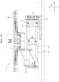
- Fig. 10 is a front view showing a configuration of a load cell scale 1 having the load cell 10 according to the present modification example.
- Fig. 11 is a front view showing the configuration of the load cell 10 according to the present modification example.
- Figs. 12-14 are figures showing the operations of the load cell 10 according to the present modification example.
- the load cell scale 1 has the load cell 10, the upper support member 20, the lower support member 30, the weighting tray 40, and the base plate 50.
- the upper support member 20 is connected to the weighting tray 40 and the tip end of the load cell 10
- the lower support member 40 is connected to the base end of the load cell 10 and the base plate 50.
- the tip end of the load cell 10 is connected to the upper support member 20 to receive the force from the weighting tray 40.
- the base end of the load cell 10 and the lower support member 30 are connected with each other and then fixed to the base plate 50.
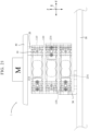
- Fig. 10 shows that the weighted object having the weight M is disposed on the weighting tray 40 of the load cell scale 1.
- the load cell 10 has the configuration that the tip-end load cell unit 110 and the base-end load cell unit 130 are integrated in the direction of the longitudinal axis.
- each of the tip-end load cell unit 110 and the base-end load cell unit 130 has a first region 141 and a second region 142.
- two second regions 142 are positioned at two sides of the first region 141.
- the regions 141 of the tip-end load cell unit 110 and the base-end load cell unit 130 are designated as deformation regions and the regions 141 are shown by being surrounded by broken lines.
- the first region 141 is formed between the second region 142 at the tip end side and the second region 142 at the base end side.
- the tip-end load cell unit 110 and the base-end load cell unit 130 of the load cell 10 according to the present modification example have the same configurations with that of the load cell 10A according to the above-described first modification example of the first embodiment.
- the load cell 10 according to the present modification example has the configuration of using two load cells 10Aaccording to the above-described first modification example of the first embodiment to achieve the integrated configuration in the direction of the longitudinal axis.
- each of the tip-end load cell unit 110 and the base-end load cell unit 130 of the load cell 10 according to the present modification example has the stopper member 232 (second position-restriction member) formed in the T shape and the protrusion 231 (first position-restriction member) formed at the tip end side of the columnar body 100 of the load cell 10. More specifically, for example, as shown in Fig.
- the protrusion 231 and the tip-end free portion 2322 of the stopper member 232 are disposed in the second region 142 at the tip end side, and the base-end fixing portion 2321 of the stopper member 232 is fixed in the second region 142 at the base end side. Accordingly, the stopper member 232 is formed to be across the first region 141 of the tip-end lad cell unit 110.
- a combination of the protrusion (first position-restriction member) 231 formed in the columnar body 100 and the stopper member (second position-restriction member) 232 is defined as a position-restriction mechanism 210.
- the base-end load cell unit 130 has the position-restriction mechanism 210 configured from the protrusion (first position-restriction member) 231 formed in the columnar body 100 and the stopper member (second position-restriction member) 232.
- the position-restriction mechanism is configured to protect the first region 141 as the deformation region in the base-end load cell unit 130 and the tip-end load cell unit 110.
- a penetration hole 2322 having an internal diameter larger than the diameter of the protrusion 231 is formed in the tip-end free portion 2322 of the stopper member 232.
- the elastic deformation does not occur in the tip-end load cell unit 110, and the protrusion 231 is freely movable in the penetration hole 232 and accommodated therein.
- the load cell 10 according to the present modification example has the configuration such that an alignment of the protrusion (first position-restriction member) 231 formed in the columnar body 100 and the stopper member (second position-restriction member) 232 may be performed with a better accuracy.
- the base-end load cell unit 130 of the load cell 10 according to the present modification example has the same configuration with the above-described tip-end load cell unit 110 and the description will be omitted.
- the stopper member 232 is formed in the substantially T shape, and the stopper member 232 is a plate-shaped member formed from the metal material having a suitable rigidity such as the iron and the like.
- the configuration of the stopper member 232 is not limited thereto.
- the stopper member 232 may be suitably formed in a shape besides the T shape.
- the stopper member 232 As shown in Fig. 12 , the stopper member 232 according to the present modification example is formed to have the step portion 254, however, the configuration of the stopper member 232 is not limited thereto. Similar to the above-described embodiments and corresponding modification examples, the load cell 10 may be configured to have the intermediate portion 250 that is sandwiched by the stopper member 232 and the columnar body 100.
- the maximum weighting M1 increase to the maximum weighting M2 in the sequence from the tip-end load cell unit 110 to the base-end load cell unit 130.
- the resolution (measurement accuracy) of the tip-end load cell unit 110 and the base-end load cell unit 130 may be different.
- each protrusion (first position-restriction member) 231 is positioned in the corresponding penetration hole 2323 and the protrusion 231 does not contact with the internal surface of the corresponding penetration hole 2323.
- the protrusion 231 is freely movable in the corresponding penetration hole 2323.
- the weight M of the weighted object is less than the maximum weighting M1 of the tip-end load cell unit 110 of the load cell 10
- the weight M of the weighted object applies on the load cell 10 as the load.
- the elastic deformation occurs in the penetration hole 151 (first region 141) as the strain portion of the tip-end load cell unit 110, however there is almost no elastic deformation occurring in the first region of the base-end load cell unit 130.
- the elastic deformation occurs in the first region 141 of the tip-end load cell unit 110 such that the protrusion 231 moves in the penetration hole 2323, however, the protrusion 231 does not contact with the internal surface of the penetration hole 2323.
- the first region 141 of the tip-end load cell unit 110 is deformed to reach the limit of the elastic deformation such that the protrusion 231 contacts with the internal surface of the penetration hole 2323.
- the protrusion (first position-restriction member) 231 of the tip-end load cell unit 110 contacts and engages with the internal surface of the penetration hole 2323 such that the stopper member (second position-restriction member) 232 and the columnar body 100 in the tip-end load cell unit 110 become the integrated configuration.
- the first region 141 of the tip-end load cell unit 110 almost reaches the limit of the elastic deformation; however, there is almost no elastic deformation occurring in the first region 141 of the base-end load cell unit 130.
- the weight M of the weighted obj ect applies to the base-end load cell unit 130 as the load and the elastic deformation occurs in the first region 141 as the strain portion in the base-end load cell unit 130.
- the tip-end cell unit 110 may be recognized as part of the base-end cell unit 130.
- the protrusion 231 moves in the penetration hole 2323 in response to the elastic deformation amount of the first region 141.
- the protrusion 231 does not contact with the internal circumferential surface of the penetration hole 2323.
- the load cell scale 1 it is possible to measure the weight M of the weighted object by detecting the electrical signals indicating the elastic deformation amount of the first region 141 of the base-end load cell unit 130.
- both of the tip-end load cell unit 110 and the base-end load cell unit 130 enter the state in which the tip-end load cell unit 110 and the base-end load cell unit 130 are deformed to reach the limit of elastic deformation.
- the protrusion 231 contacts and engages with the internal circumferential surface of the corresponding penetration hole 2323.
- the stopper member 232 and the columnar body 100 in the tip-end load cell unit 110 and the base-end load cell unit 130 become the integrated configuration. Accordingly, in the load cell 10 according to the present modification example, it is possible to prevent the tip-end load cell unit 110 and the base-end load cell unit 130 from deforming exceeding the limit of the elastic deformation.
- the configuration of the position-restrict ion mechanism 210 configured from the protrusion (first position-restriction member) 231 and the stopper member (second position-restriction member) 232 is different from that according to the above-described second embodiment, however, the same effect with the above-described second embodiment may be achieved.
- the load cell 10 according to the second modification example of the present embodiment will be described with reference to Figs. 15 and 16 .
- the load cell according to the present modification example has the configuration that the tip-end load cell unit 110 and the base-end load cell unit 130 is integrated in the direction of the longitudinal axis.
- the tip-end load cell unit 110 and the base-end load cell unit 130 have the same configuration as that of the load cell 10B according to the above-described second modification example of the first embodiment.
- the tip-end load cell unit 110 and the base-end load cell unit 130 are configured to have position-restriction tank (first position-restriction member) 231 (see Fig. 15 ) connected and fixed to the columnar body 100 and the stopper member (second position-restriction member) 232 formed in the substantial T shape.
- position-restriction tank first position-restriction member
- second position-restriction member second position-restriction member
- At least part of the tip-end free portion 2322 of the stopper member 232 is covered by the corresponding position-restriction tank 231 in the direction of the longitudinal axis. In other words, at least part of the tip-end free portion 2322 of the stopper member 232 is accommodated in the position-restriction tank 231.
- the tip-end free portion 2322 of the stopper member 232 and the position-restriction tank 231 are separated by a predetermined interval.
- the interval between the tip-end free portion of the stopper member 232 and the position-restriction tank 231 is suitably determined according to the maximum elastic deformation amount of the strain portion corresponding to the maximum weighting M1 of the tip-end load cell unit 110 and the maximum weighting M2 of the base-end load cell unit 130.
- the maximum weighting M1 of the tip-end load cell unit 110 may be less than the maximum weighting M2 of the base-end load cell unit 130.
- the step portion 154 having the width H3 in the height direction may be provided in the base-end fixing portion 2321 of the tip-end load cell unit 110 of the load cell 10 according to the present modification example.
- the load cell 10 according to the present modification example has the step portion 154 so as to prevent the base-end fixing portion 2321 of the stopper member 232 from unintentionally contacting with the internal surface of the groove portion 152. Accordingly, when the weighted object is disposed on the load cell 10, the deformation amount of the columnar body 100 can be correctly recognized.
- the step portion 154 is formed in only part of the base-end fixing portion 2321 of the stopper member 232 such that it is possible to retain the rigidity of the tip-end load cell unit 110.
- the base-end fixing portion 2321 of the base-end load cell unit 130 is separated from the internal surface of the groove portion 152 for an interval is described, however, the present modification example is not limited thereto.
- the base-end load cell unit 130 may have the base-end fixing unit 2321 where the step portion 154 formed therein.
- a combination of the position-restriction tank (first position-restriction member) 231 and the stopper member (second position-restriction member) 232 is defined as the position-restriction mechanism 210. Accordingly, according to the load cell 10 disclosed in the present modification example, similar to the above-described embodiments and modification examples, the movement range of the stopper member 232 is restricted by the position-restriction tank 231 such that it is possible to prevent the tip-end load cell unit 110 and the base-end load cell unit 130 from deforming to exceed the limit of the elastic deformation so as to avoid the malfunctions.
- the stopper member 232 engages with the internal surface of the position-restriction tank 231 of the tip-end load cell unit 110 to be in the integrated state, and the weight M of the weighted object applies on the base-end load cell unit 130 as the load.
- the tip-end free portion 2322 of the stopper member 232 of the base-end load cell unit 130 moves in the corresponding position-restriction tank 231, however, the tip-end free portion 2322 does not contact with the internal surface of the position-restriction tank 231.
- the weight M of the weighted object is measured by detecting the signals indicating the elastic deformation amount in the strain portion of the base-end load cell unit 130.
- Fig. 17 shows a configuration of the load cell 10 according to the third modification example of the present embodiment.
- the load cell 10 according to the present modification example is configured to have the tip-end load cell unit 110, an intermediate load cell unit 120, and the base-end load cell unit 130 fixed to the columnar body 100 sequentially in the sequence from the tip end side toward the base end side in the direction of the longitudinal axis.
- each of the tip-end load cell unit 110, the intermediate load cell unit 120, and the base-end load cell unit 130 has the stopper member 200 fixed to the groove portion 152 formed in the lateral surface 102 of the columnar body 100.
- the maximum weighting M1 of the tip-end load cell unit 110, the maximum weighting M2 of the intermediate load cell unit 120, and the maximum weighting M3 of the base-end load cell unit 130 may be set to increase in this sequence.
- the tip-end load cell unit 110, the intermediate load cell unit 120, and the base-end load cell unit 130 may have different resolutions (measurement accuracies).
- the load cell 10 Similar to the load cell 10 (see Fig. 6 ) according to the above-described second embodiment, the load cell 10 according to the present modification example has the configuration such that when the weighted object having the weight M larger than the maximum weighting of each load cell unit or the unintentional impact applies on the load cell scale 1, it is possible to prevent the deformation exceeding the limit of the elastic deformation and malfunctions occurring in each load cell unit 110, 120, 130.
- the load cell 10 according to the present modification example compared with the load cell 10 according to the above-described second embodiment, it is possible to further expand the maximum weighting of the load cell scale 1 with a simple configuration. Accordingly, it is possible to configure a complex load cell scale having the maximum weighting and resolution as desired by combining various load cell units disclosed in the above-described embodiments and modification examples of the present invention.
- the tip-end load cell unit 110, the intermediate load cell unit 120, and the base-end load cell unit 130 have the same configuration
- the present modification example is not limited thereto.
- the tip-end load cell unit 110, the intermediate load cell unit 120, and the base-end load cell unit 130 may be configured by combining the various configurations according to the above-described first embodiment and the corresponding modification examples.
- Figs. 18 and 19 are front views showing the configuration of part of the load cell 10 according to the present embodiment, more specifically, showing the configuration of the tip-end load cell unit 110 of the load cell 10.
- Fig. 20 is a front view showing the configuration of load cell according to the present embodiment.
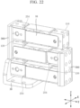
- Figs. 21 and 22 are front view and perspective view showing the load cell scale 1 having the load cell 10 respectively.
- Figs. 23 and 24 are front views showing the operations of the load cell 10 according to the present embodiment.
- the load cell 10 according to the present embodiment is configured to have three load cell units connected with each other. More specifically, the load cell 10 according to the present embodiment is configured to have the tip-end load cell unit 110 and the base-end load cell unit 130 indirectly connected via the intermediate load cell unit 120.
- each of the tip-end load cell unit 110, the intermediate load cell unit 120, and the base-end load cell unit 130 according to the present embodiment is configured by connecting the stopper member (second position-restriction member) 232 to the lateral surface of the columnar body 100.
- the stopper member (second position-restriction member) 232 is connected to the lateral surface of the columnar body 100.
- the first region 141 having the penetration hole 151 formed as the strain portion and two second regions 142 formed at the two sides of the first region 141 are formed in an intermediate portion in the direction of the longitudinal axis of the columnar body 100.
- the first region 141 is formed as the deformation region of the tip-end load cell unit 110.
- the tip-end load cell unit 110 has the base-end fixing portion 2321 of the stopper member 232 that is connected and fixed to the columnar body 100 by the fixing mechanism 150.
- the penetration hole 2323 is formed in the tip-end free portion 2322 of the tip-end load cell unit 110, and the protrusion (first position-restriction member) 231 formed to protrude from the lateral surface at the tip end side of the columnar body 100 is positioned in the penetration hole 2323.
- the external diameter of the protrusion 231 is smaller than the internal diameter of the penetration hole 2323 such that the protrusion 231 is freely movable in the penetration hole 2323.
- the combination of the protrusion (first position-restriction member) 231 formed in the columnar body 100 and the stopper member (second position-restriction member) 232 operates as the position-restriction mechanism 210 of the tip-end load cell unit 110.
- the intermediate load cell unit 120 and the base-end load cell unit 130 may have almost the same configuration with that of the tip-end load cell unit 110.
- the present embodiment in order to make the description easy, an example that in Figs. 18 and 19 , the right side in the figures is the base end side of the tip-end load cell unit 110, and the left side in the figures is the tip end side of the tip-end load cell unit 110 is described, however, the present embodiment is not limited thereto. For example, as shown in Figs. 18 and 19 , the right side in the figures is the base end side of the tip-end load cell unit 110, and the left side in the figures is the tip end side of the tip-end load cell unit 110 is described, however, the present embodiment is not limited thereto. For example, as shown in Figs.
- the base end side of the tip-end load cell unit 110 and the tip end side of the intermediate load cell unit 120 are connected with each other by a connection member 300 having a predetermined rigidity, and the base end side of the intermediate load cell unit 120 and the tip end side of the base end load cell unit 130 are connected with each other by the connection member 300, the extending direction from the base end side toward the tip end side of each load cell unit is not particularly limited.
- the three load cell units 110, 120, 130 only have to be connected with each other to form a hairpin curve shape.
- connection member 300 when the weighted object having the weight M is disposed on the weighting tray 40 of the load cell scale 1 as described below, it is preferable that the connection member 300 according to the present embodiment has the rigidity suitable for supporting the weighted object, the tip-end load cell unit 110, and the intermediate load cell unit 120, however, the shape and the material of the connection member 300 are not particularly limited.
- the load cells according to the above-described embodiments and modification examples are configured by the integrated configuration of various load cell units in the direction of the longitudinal axis, that is, in the horizontal direction.
- the tip-end load cell unit 110, the intermediate load cell unit 120, and the base-end load cell unit 130 according to the present embodiment are stacked in the height direction (Z-axis direction, vertical direction) of the load cell 10.
- the load cell 10 according to the present embodiment has such a module construction such that it is easy to expand the maximum weighting of the load cell 10 by adding the load cell unit.
- the load cell 10 configured from three load cell units of the tip-end load cell unit 110, the intermediate load cell unit 120, and the base-end load cell unit 130 is described, however, the present embodiment is not limited thereto.
- the load cell 10 may be configured by the tip-end load cell unit 110 and the base-end load cell unit 130 only, or the load cell 10 may be configured by equal to or more than four load cell units that is not shown in figures.
- Figs. 21 and 22 the configuration of the load cell scale 1 having the load cell 10 that is configured by using the connection member 300 to connect the tip-end load cell unit 110, the intermediate load cell unit 120, and the base-end load cell unit 130 is shown.
- the weighting tray 40 is connected to the tip end side of the tip-end load cell unit 110 via the upper support member 20.
- the base plate 50 is connected to the base end side of the base-end load cell unit 130 via the lower support member 30. Accordingly, when the weighted member having the weight M is disposed on the weighting tray 40 of the load cell scale 1, the weight M of the weighted object can be measured by detecting the deformation amount of each load cell unit in the load cell 10.
- the load cell scale 1 having the load cell 10 according to the present embodiment has the load cell 10 configured from three load cell units 110, 120, 130, the maximum weighting suitable for weighting is in three steps.
- the maximum weighting M1 for example, three kilograms
- the maximum weighting M2 for example, six kilograms
- the maximum weighting M3 for example, fifteen kilograms
- the tip-end load cell unit 110, the intermediate load cell unit 120, and the base-end load cell unit 130 may have different resolutions (measurement accuracies) .
- the weight M of the weighted object applies to the tip-end load cell unit 110 as the load, and the elastic deformation occurs in the first region 141 as the deformation portion in the tip-end load cell unit 110 such that the protrusion 231 provided in the columnar body 100 moves in the penetration hole 2323 formed in the tip-end free portion 2322 of the stopper member 232; however, the protrusion 231 does not contact with the internal circumferential surface of the penetration hole 2323.
- the weight M of the weighted object can be measured by detecting the electrical signals indicating the elastic deformation amount of the first region of the tip-end load cell unit 110.
- the protrusion 231 formed in the columnar body 100 of the tip-end load cell unit 110 contacts with the internal circumferential surface of the penetration hole 2323 formed in the tip-end free portion 2322 of the stopper member 232.
- the protrusion 231 cannot move in the penetration hole 2323 formed in the stopper member 232 such that the elastic deformation of the first region 141 of the tip-end load cell unit 110 is restricted by the stopper member 232. Accordingly, the columnar body 100 and the stopper member 232 in the tip-end load cell unit 110 become the integrated configuration so as to be recognized as part of the configuration at the tip end side of the intermediate load cell unit 120.
- the weight M of the weighted member applies to the intermediate load cell unit 120 as the load, and the protrusion 231 in the intermediate load cell unit 120 moves in the penetration hole 2323 formed in the corresponding stopper member 232.
- the weight M of the weighted object can be measured by detecting the signals indicating the elastic deformation amount of the first region 141 in the intermediate load cell unit 120.
- the first region 141 of the tip-end load cell unit 110 has reached the limit of the elastic deformation; however, the elastic deformation may occur in the first regions 141 of the intermediate load cell unit 120 and the base-end load cell unit 130.
- the protrusion 231 formed in the columnar body 100 contacts the internal circumferential surface of the penetration hole 2323 formed in the corresponding stopper member 232.
- the columnar body 100 and the stopper member 232 become the integrated configuration in each of the tip-end load cell unit 110 and the intermediate load cell unit 120.
- the weight M of the weighted object applies to the base-end load cell unit 130 as the load such that in the base-end load cell unit 130, the elastic deformation occurs in the first region and the protrusion 231 formed in the columnar body 100 moves in the penetration hole 2323 of the corresponding stopper member 232. Similar to the above-described cases, the weight M of the weighted object can be measured by detecting the signals indicating the elastic deformation amount in the first region 141 of the base-end load cell unit 130.
- the load cell 10 disclosed in the present embodiment similar to the above-described embodiments and modification examples, it is possible to avoid the deformation exceeding the limit of the elastic deformation in the tip-end load cell unit 110, the intermediate load cell unit 120, and the base-end load cell unit 130 and prevent the malfunctions of the load cell 10.
- the load cell 10 according to the first modification example of the present embodiment is configured by using the connection member 300 to connect the tip-end load cell unit 110, the intermediate load cell unit 120, and the base-end load cell unit 130 in the state of being stacked in the vertical direction.
- the tip-end load cell unit 110, the intermediate load cell unit 120, and the base-end load cell unit 130 have the same configuration as that of the load cell 10 (see Figs. 1-3 ) according to the first embodiment.
- Fig. 26 shows the configuration of the load cell 10 according to the second modification example of the present embodiment.
- the load cell 10 according to the present modification example is configured by using the connection member 300 to connect the tip-end load cell unit 110 and the base-end load cell unit 130 in the state of being stacked in the vertical direction.
- the tip-end load cell unit 110 and the base-end load cell unit 130 have the same configuration as that of the load cell 10 (see Figs. 1-3 ) according to the first embodiment. It is possible to configure a further compact load cell scale 1 using the load cell 10 according to the present modification example and correspond to the weighting for a relative light weighted object.
- Fig. 27 shows the configuration of the load cell according to the third modification example of the present embodiment.
- the load cell 10 according to the present modification example is different from the second modification example of the present embodiment in the configurations of the tip-end load cell unit 110 and the base-end load cell unit 130. More specifically, the tip-end load cell unit 110 and the base-end load cell unit 130 have the same configuration as that of each load cell unit of the load cell 10 (see Figs. 18 and 19 ) according to the third embodiment.
- the present embodiment is not limited thereto.
- the several modification examples of the present embodiment are used to describe the feature that it is easy to expand the weighting of the load cell using the modulated load cell units in the load cell 10.
- the several load cell units included in the load cell have the same configuration, however, the present embodiment is not limited thereto.
- the load cell 10 according to the present embodiment and each modification example the load cell having different configuration according to the first embodiment and the corresponding modification examples may be suitably combined.
- the load cell 10 disclosed in the present embodiment and each modification example it is easy to expand the weighting and it is possible to avoid the deformation exceeding the limit of the elastic deformation in each load cell unit configuring the load cell 10 by using a simple configuration so as to prevent the malfunctions of the load cell 10.
- Fig. 18 is a perspective view showing a configuration of the load cell according to the present embodiment.
- Fig. 29 is a cross-sectional view along the break line A-A in Fig. 28 .
- the load cell 10 according to the present embodiment is configured to have a protection member 500 attached to the load cell 10 according to the second embodiment.
- the protection member 500 connected to the tip-end load cell unit 110 for example, is fixed to the tip end surface of the tip-end load cell unit 110 in a state of covering at least part of the tip-end load cell unit 110.
- the protection member 500 has two second stopper members 510 at positions facing the plate-shaped member 520 along the height direction of the load cell 10.
- the second stopper member 510 may be configured by using the screw attached to the top plate of the protection member 500, however, the second stopper member 510 is not limited thereto.
- the second stopper member 510 may be a pin protruding from the top plate of the protection member 500 toward the plate-shaped member 520. As shown in Fig.
- the second stopper member 510 and the plate-shaped member 520 are separated from each other by a distance h.
- the second stopper member 510 has a width in the short direction of the plate-shaped member 520 such that in the case when the top plate of the protection member 500 receives the external force to be bent, the second stopper member 510 moves downward to contact with the plate-shaped member 520.
- the protection member 500 and the plate-shaped member 520 may be formed from the metal materials having the predetermined rigidity.
- the combination of the protection member 500 and the plate-shaped member 520 fixed to the load cell 10 is configured to protect each configuration of the load cell 10 from any unintentional external impact. More specifically, in the case when the external force that is much larger than the maximum weighting of the load cell 10 applies on the load cell 10, for example, when a baggage having a weight of 150 kilograms that is 10 times of the maximum weighting as 15 kilograms of the load cell 10 falls and collides with the load cell 10, it is possible that the real-time impact to the load cell 10 is much larger than the considerable impact to the stopper member 232 provided in the load cell 10. In this state, since the impact cannot be absorbed only by the stopper member 232, it is possible that the deformation exceeding the limit of elastic deformation occurs in the load cell 10 so as to generate the permanent strain therein.
- the force due to the impact firstly applies to the protection member 500.
- the protection member 500 receives the force
- the top plate bends downwardly in the height direction of the load cell 10 to deform.
- the second stopper members 510 provided in the protection member 500 moves downwardly toward the plate-shaped member 520.
- the distance h between the second stopper members 510 and the plate-shaped member 520 decreases.
- the second stopper members 510 moves downwardly until the second stopper members 510 contact with the plate-shaped member 520.
- the protection member 500 is connected with the tip-end load cell unit 110 of the load cell 10, part of the force is transmitted to the tip-end load cell unit 110 such that stopper member 232 included in the tip-end load cell unit 110 moves simultaneously. Furthermore, in some cases, the stopper member 232 included in the base-end load cell unit 130 also moves simultaneously.
- the second stopper member 510 included in the protection member 500, the stopper members 232 provided in the tip-end load cell unit 110 and the base-end load cell unit 130 of the load cell 10 moves simultaneously such that the protection member 500, the columnar body 100 of the load cell 10 and the various stopper member 232 contact with each other to become the integrated configuration.
- the protection member 500 has a large force receiving area for receiving the force from the height direction of the load cell 10 and the protection member 500 is formed from the material having the predetermined rigidity. Accordingly, it is considerable that the rigidity of the configuration formed by combining the columnar body 100 and the stopper member 232 of the load cell 10 together with the protection member 500 can be significantly improved.
- the stopper member 232 is not provided in the tip-end load cell unit 110, it is also possible to avoid the unintentional deformation in the tip-end load cell unit 110 and the base-end load cell unit only by the operations of the protection member 500.
- the load cell 10 due to the load cell 10 according to the present embodiment, even if the unintentional impact applies to the load cell 10, it is possible to avoid the deformation exceeding the limit of the elastic deformation in each load cell unit of the load cell 10 by the protection member 500 so as to prevent the malfunctions in the load cell 10.
- the second stopper member 510 in the case when the second stopper member 510 is configured by the screw, it is considerable to adjust the magnitude of the impact that can be absorbed by the protection member 500 by only adjusting the distance between the second stopper member 510 and the plate-shaped member 520.
- the configuration of the protection member 500 in the load cell 10 according to the present embodiment is described based on the configuration example shown in Figs. 28 and 29 , however, the configuration of the protection member 500 is not limited thereto.
- the second stopper member 510 may be provided in the upper support member 20 (see Fig. 10 ) according to the second embodiment.
- a load cell configured to restrict the deformation occurring in the load cell in a case when the load exceeding the weighting applies to the load cell, and a load cell scale having the load cell. Also, according to the embodiments described above, it is possible to provide a load cell scale configured by several load cells having different weightings so as to correctly switch the weightings and measure the weight of the weighted object.
Landscapes
- Physics & Mathematics (AREA)
- General Physics & Mathematics (AREA)
- Measurement Of Force In General (AREA)
- Force Measurement Appropriate To Specific Purposes (AREA)
Claims (11)
- Wägezellenwaage (1), umfassend:einen Wägezellenteil (10), der in einer säulenförmigen Gestalt ausgebildet ist, wobei der Wägezellenteil (10) eine obenliegende Fläche (101), die sich entlang einer Längsachse (L) erstreckt, und eine seitliche Fläche (102) aufweist, welche die obenliegende Fläche (101) schneidet, und wobei der Wägezellenteil (10) eine erste Wägezelle (110) mit einer ersten Gewichtung und eine zweite Wägezelle (130) mit einer zweiten Gewichtung aufweist,wobei im Wägezellenteil (10) die erste Wägezelle (110) und die zweite Wägezelle (130) entlang einer Längsrichtung oder einer Höhenrichtung anzuordnen sind, undwobei der Wägezellenteil (10) einen Belastungsabschnitt (151) aufweist, der dazu befähigt ist, sich elastisch zu verformen, und der Belastungsabschnitt (151) ausgehend von der seitlichen Fläche in einer Querrichtung, welche rechtwinklig zu der Längsrichtung ist, in die erste Wägezelle (110) und die zweite Wägezelle (130) eindringt,dadurch gekennzeichnet, dass die Wägezelle weiterhin Folgendes umfasst:einen Anschlagteil (200), der dafür ausgelegt ist, eine Verformung zu beschränken, die in dem Wägezellenteil (10) aufgrund einer Last auftritt, welche einen vorbestimmten Wert überschreitet und auf den Wägezellenteil (10) einwirkt, wobei der Anschlagteil (200) derart ausgestaltet ist, dass er entweder der ersten Wägezelle (110) oder der zweiten Wägezelle (130) entspricht,wobei der Anschlagteil (200) ein plattenförmiges Glied ist, das derart ausgebildet ist, dass es sich entlang der Längsrichtung erstreckt,wobei der Anschlagteil (200) Folgendes umfasst:einen befestigenden Endabschnitt, welcher an der seitlichen Fläche (102) des Wägezellenteils (10) befestigt ist; undeinen freiliegenden Endabschnitt, welcher entlang der Längsachse (L) von dem befestigenden Endabschnitt getrennt ist, wobei der freiliegende Endabschnitt dafür ausgelegt ist, die lastbedingte elastische Verformung des Wägezellenteils (10) in einem Zustand zu beschränken, in welchem der befestigende Endabschnitt an der seitlichen Fläche (102) befestigt ist,wobei der Anschlagteil (200) einen ersten Anschlag (200) und einen zweiten Anschlag (200) aufweist, wobei diese der ersten Wägezelle (110) beziehungsweise der zweiten Wägezelle (130) entsprechen, undwobei der befestigende Endabschnitt des ersten Anschlags (200) und der freiliegende Abschnitt des zweiten Anschlags (200) auf der seitlichen Fläche (102) aneinander angrenzen.
- Wägezellenwaage (1) gemäß Anspruch 1, wobei der befestigende Endabschnitt zumindest des ersten Anschlags (200) oder des zweiten Anschlags (200) derart ausgebildet ist, dass er eine dritte Breite (H3) aufweist, die zwischen der ersten Breite (H1) und der zweiten Breite (H2) liegt.
- Wägezellenwaage (1) gemäß Anspruch 1,wobei der Anschlagteil, wenn die Abmessungen des Anschlagteils (200) in einer Höhenrichtung, die rechtwinklig zur obenliegenden Fläche (101) ist, als Breite des Anschlagteils (200) definiert sind, eine erste Breite (H1) am befestigenden Endabschnitt, eine zweite Breite (H2) in einem Bereich, in welchem der Belastungsabschnitt (151) entlang der Längsachse ausgebildet ist, und eine vierte Breite (H4) am freiliegenden Endabschnitt aufweist, unddie erste Breite (H1) des Anschlagteils (200) breiter als die zweite Breite (H2) des Anschlagteils (200) ist.
- Wägezellenwaage (1) gemäß Anspruch 1 oder 2,wobei der Anschlagteil (200) einen positionsbeschränkenden Auffangbehälter (231, 2311) aufweist, der dafür ausgelegt ist, eine Betätigung des freiliegenden Endabschnitts zu beschränken,der freiliegende Endabschnitt in dem positionsbeschränkenden Auffangbehälter (231, 2311) in der Höhenrichtung vorliegt, undwobei der positionsbeschränkende Auffangbehälter (231, 2311) und der befestigende Endabschnitt des ersten Anschlags (200) auf der seitlichen Fläche (102) aneinander angrenzen.
- Wägezellenwaage (1) gemäß einem beliebigen der Ansprüche 1 bis 4,wobei die seitliche Fläche (102) der ersten Wägezelle (110) und der zweiten Wägezelle (130) eine Nut (152) aufweist, die entlang der Richtung der Längsachse (L) in einem Bereich ausgebildet ist, in welchem der Belastungsabschnitt (151) in der Höhenrichtung rechtwinklig zur obenliegenden Fläche (101) ausgebildet ist; undder erste Anschlag (200) und der zweite Anschlag (200) auf derselben Fläche in der Nut (152) nebeneinander angeordnet sind.
- Wägezellenwaage (1) gemäß Anspruch 5, wobei der freiliegende Endabschnitt des ersten Anschlags (200) und der freiliegende Endabschnitt des zweiten Anschlags (200) dafür ausgelegt sind, die elastische Verformung des Wägezellenteils (10) zu beschränken, indem sie mit derselben Nut in Kontakt kommen.
- Wägezellenwaage (1) gemäß einem beliebigen der Ansprüche 1 bis 6, wobei sie weiterhin ein Zwischenglied (250) aufweist, das derart ausgebildet ist, dass es sandwichartig zwischen dem Wägezellenteil (10) und einem Abschnitt angeordnet ist, in welchem der Anschlagteil (200) entlang der Querrichtung an der seitlichen Fläche (102) befestigt ist.
- Wägezellenwaage (1) gemäß einem beliebigen der Ansprüche 1 bis 7, wobei eine erste Länge des ersten Anschlags (200) entlang der Richtung der Längsachse (L) des ersten Anschlags (200) sich von einer zweiten Länge des zweiten Anschlags (200) entlang der Richtung der Längsachse (L) des zweiten Anschlags (200) unterscheidet.
- Wägezellenwaage (1) gemäß einem beliebigen der Ansprüche 1 bis 8,wobei, wenn die Last, welche auf die erste Wägezelle (110) einwirkt, geringer als die erste Gewichtung ist, die elastische Verformung in der ersten Wägezelle (110) erfolgt und der freiliegende Endabschnitt des ersten Anschlags (200) sich gegenüber der ersten Wägezelle (110) bewegt, undwenn die Last, welche auf die erste Wägezelle (110) einwirkt, höher als die erste Gewichtung und geringer als die zweite Gewichtung ist, die elastische Verformung in der zweiten Wägezelle (130) erfolgt und der freiliegende Endabschnitt des zweiten Anschlags (200) sich gegenüber der zweiten Wägezelle (130) derart bewegt, dass er einen Zustand annimmt, in welchem der erste Anschlag (200) und die erste Wägezelle (110) miteinander in Eingriff stehen.
- Wägezellenwaage (1) gemäß Anspruch 1 oder 2,wobei die erste Wägezelle (110) und die zweite Wägezelle (130) ein erstes positionsbeschränkendes Glied (231) beziehungsweise ein zweites positionsbeschränkendes Glied (231) aufweisen,der erste Anschlag (200) und der zweite Anschlag (200) ein erstes positionsbeschränkendes Loch (2323) und ein zweites positionsbeschränkendes Loch (2323) aufweisen, wobei diese in den freiliegenden Endabschnitten des ersten Anschlags (200) und des zweiten Anschlags (200) ausgebildet sind und Weiten haben, die sich zum Einführen des ersten positionsbeschränkenden Glieds (231) beziehungsweise des zweiten positionsbeschränkenden Glieds (231) eignen,wobei, wenn die Last, welche auf den Wägezellenteil (10) einwirkt, geringer als die erste Gewichtung ist, das erste positionsbeschränkende Glied (231) und das zweite positionsbeschränkende Glied (231) in dem ersten positionsbeschränkenden Loch (2323) beziehungsweise dem zweiten positionsbeschränkenden Loch beweglich sind,wobei, wenn die Last, welche auf den Wägezellenteil (10) einwirkt, gleich der ersten Gewichtung oder höher als diese und geringer als die zweite Gewichtung ist, das erste positionsbeschränkende Glied (231) mit dem ersten positionsbeschränkenden Loch (2323) in Eingriff steht und das zweite positionsbeschränkende Glied (231) in dem zweiten positionsbeschränkenden Loch (2323) beweglich ist, undwobei, wenn die Last, welche auf den Wägezellenteil einwirkt, höher als die zweite Gewichtung ist, das erste positionsbeschränkende Glied (231) und das zweite positionsbeschränkende Glied (231) mit dem ersten positionsbeschränkenden Loch (2323) beziehungsweise dem zweiten positionsbeschränkenden Loch in Eingriff stehen.
- Wägezellenwaage (1) gemäß einem beliebigen der Ansprüche 1 bis 10, wobei sie darüber hinaus ein Schutzglied (500) umfasst, welches an der ersten Wägezelle (110) befestigt ist,
wobei, wenn die Last, welche einwirkt, höher als die erste Gewichtung ist, die erste Wägezelle (110) und das Schutzglied (500) gleichzeitig dahingehend wirken, dass ein verhindert wird, dass in der ersten Wägezelle (110) eine dauerhafte Belastung auftritt.
Applications Claiming Priority (2)
| Application Number | Priority Date | Filing Date | Title |
|---|---|---|---|
| CN201810955649.7A CN108692798A (zh) | 2018-08-21 | 2018-08-21 | 称重传感器及包括其的称重秤 |
| PCT/JP2019/007929 WO2020039624A1 (ja) | 2018-08-21 | 2019-02-28 | ロードセルおよびロードセル秤 |
Publications (3)
| Publication Number | Publication Date |
|---|---|
| EP3842769A1 EP3842769A1 (de) | 2021-06-30 |
| EP3842769A4 EP3842769A4 (de) | 2022-05-25 |
| EP3842769B1 true EP3842769B1 (de) | 2025-02-12 |
Family
ID=63841257
Family Applications (1)
| Application Number | Title | Priority Date | Filing Date |
|---|---|---|---|
| EP19852531.3A Active EP3842769B1 (de) | 2018-08-21 | 2019-02-28 | Wägezelle und wägezellenwaage |
Country Status (5)
| Country | Link |
|---|---|
| US (1) | US11933662B2 (de) |
| EP (1) | EP3842769B1 (de) |
| JP (1) | JP7362072B2 (de) |
| CN (2) | CN108692798A (de) |
| WO (1) | WO2020039624A1 (de) |
Families Citing this family (6)
| Publication number | Priority date | Publication date | Assignee | Title |
|---|---|---|---|---|
| CN108692798A (zh) * | 2018-08-21 | 2018-10-23 | 上海寺冈电子有限公司 | 称重传感器及包括其的称重秤 |
| CN109798955A (zh) * | 2019-03-12 | 2019-05-24 | 江苏立华牧业股份有限公司 | 活禽智能称重方法、系统、智能活禽秤和终端 |
| CN111189521B (zh) * | 2020-02-24 | 2025-04-22 | 深圳市晨北科技有限公司 | 称重传感装置及电子秤 |
| CN114485876B (zh) * | 2021-12-30 | 2025-01-17 | 北京万集科技股份有限公司 | 称重传感器、称重系统及称重方法 |
| CN114400402B (zh) * | 2022-03-24 | 2022-06-14 | 深圳市玖木科技发展有限公司 | 一种空气净化设备的蓄电池及其供电输出连接组件 |
| CN117309122B (zh) * | 2023-11-28 | 2024-01-30 | 常州辉宏电子科技有限公司 | 一种自动识别的电子秤 |
Family Cites Families (33)
| Publication number | Priority date | Publication date | Assignee | Title |
|---|---|---|---|---|
| US3135112A (en) * | 1960-09-06 | 1964-06-02 | Baldwin Lima Hamilton Corp | Safety-load control of parallelogram type of load cell |
| US4367801A (en) * | 1978-10-06 | 1983-01-11 | Pennsylvania Scale Company | Load cell for use with electronic counting and weighing scales |
| GB2087085B (en) * | 1980-10-22 | 1984-06-27 | Avery Ltd W & T | Force transducer with multiple measuring sections |
| JPS6196422A (ja) * | 1984-10-17 | 1986-05-15 | Tokyo Electric Co Ltd | マルチレンジロ−ドセル秤 |
| JPS61246631A (ja) * | 1985-04-25 | 1986-11-01 | Tokyo Electric Co Ltd | マルチレンジロ−ドセル秤 |
| JPS61260125A (ja) * | 1985-05-15 | 1986-11-18 | Tokyo Electric Co Ltd | ロ−ドセル秤の調整装置 |
| JPS61260124A (ja) * | 1985-05-15 | 1986-11-18 | Tokyo Electric Co Ltd | マルチレンジロ−ドセル秤 |
| JPS6232324A (ja) * | 1985-08-06 | 1987-02-12 | Tokyo Electric Co Ltd | マルチレンジロ−ドセル秤 |
| JPH0638055B2 (ja) * | 1985-09-17 | 1994-05-18 | 東京電気株式会社 | マルチレンジロ−ドセル秤の計量方法 |
| JPS63201543A (ja) * | 1987-02-17 | 1988-08-19 | Sharp Corp | 歪ゲ−ジ式秤 |
| JPH02150537U (de) * | 1989-05-24 | 1990-12-26 | ||
| JP2554826Y2 (ja) * | 1991-09-25 | 1997-11-19 | アンリツ株式会社 | ロードセルのストッパ機構 |
| JPH0843184A (ja) * | 1994-07-29 | 1996-02-16 | Teraoka Seiko Co Ltd | マルチレンジロードセル秤 |
| FR2796719B1 (fr) * | 1999-07-23 | 2001-10-12 | Sidel Sa | Capteur d'effort comportant un dispositif de protection contre les surcharges |
| TW507066B (en) * | 2000-08-09 | 2002-10-21 | Tanita Seisakusho Kk | Balance composed of load sensor unit with stopper mechanism |
| JP3855780B2 (ja) * | 2002-01-29 | 2006-12-13 | 株式会社島津製作所 | 歪ゲージ式荷重センサ |
| EP1574829B1 (de) * | 2002-03-18 | 2007-04-25 | Mettler-Toledo AG | Montagevorrichtung für einen Kraftaufnehmer und Waage |
| DE102004027619B4 (de) * | 2004-06-05 | 2008-04-03 | Hottinger Baldwin Messtechnik Gmbh | Überlastsicherung für ein Kraftmesselement |
| EP1672335B1 (de) | 2004-12-14 | 2007-08-15 | Mettler-Toledo AG | Wägemodul mit einer positionspräzisen Überlastschutzvorrichtung |
| CN201096513Y (zh) * | 2007-08-17 | 2008-08-06 | 周亚敏 | 传感器的销式限位保护机构 |
| CN201107105Y (zh) * | 2007-10-24 | 2008-08-27 | 东莞市华兰海电子有限公司 | 小量程过载保护称重传感器 |
| WO2010106388A1 (fr) * | 2009-03-19 | 2010-09-23 | S.C.A.I.M.E S.A. | Capteur etanche a jauges de contrainte. |
| CN201408067Y (zh) * | 2009-05-20 | 2010-02-17 | 梅特勒-托利多(常州)精密仪器有限公司 | 称重传感器的弹性体 |
| JP2012117909A (ja) * | 2010-11-30 | 2012-06-21 | Teraoka Seiko Co Ltd | 複合ロードセル秤 |
| JP5840430B2 (ja) * | 2011-09-14 | 2016-01-06 | 大和製衡株式会社 | ロードセルおよびその製造方法 |
| JP6029859B2 (ja) * | 2012-06-01 | 2016-11-24 | 株式会社イシダ | 計量装置 |
| JP6016937B2 (ja) * | 2012-11-02 | 2016-10-26 | 株式会社エー・アンド・デイ | ロードセル |
| WO2014068762A1 (ja) * | 2012-11-02 | 2014-05-08 | 株式会社 エー・アンド・デイ | ロードセル |
| CN204405152U (zh) * | 2015-03-06 | 2015-06-17 | 霍丁格包尔文(苏州)电子测量技术有限公司 | 具有防过载自保护功能的传感器 |
| CN204612803U (zh) * | 2015-04-13 | 2015-09-02 | 上海越平科学仪器(苏州)制造有限公司 | 一种称重传感器的保护装置 |
| CN106124020A (zh) | 2016-01-20 | 2016-11-16 | 申俊 | 一种双精电子秤 |
| CN108414060A (zh) * | 2018-02-12 | 2018-08-17 | 上海寺冈电子有限公司 | 双称量电子秤 |
| CN108692798A (zh) * | 2018-08-21 | 2018-10-23 | 上海寺冈电子有限公司 | 称重传感器及包括其的称重秤 |
-
2018
- 2018-08-21 CN CN201810955649.7A patent/CN108692798A/zh active Pending
-
2019
- 2019-02-28 WO PCT/JP2019/007929 patent/WO2020039624A1/ja not_active Ceased
- 2019-02-28 US US17/269,512 patent/US11933662B2/en active Active
- 2019-02-28 EP EP19852531.3A patent/EP3842769B1/de active Active
- 2019-02-28 CN CN201910151598.7A patent/CN110849450B/zh active Active
- 2019-02-28 JP JP2020538020A patent/JP7362072B2/ja active Active
Also Published As
| Publication number | Publication date |
|---|---|
| JPWO2020039624A1 (ja) | 2021-09-02 |
| CN110849450A (zh) | 2020-02-28 |
| US11933662B2 (en) | 2024-03-19 |
| CN108692798A (zh) | 2018-10-23 |
| JP7362072B2 (ja) | 2023-10-17 |
| WO2020039624A1 (ja) | 2020-02-27 |
| CN110849450B (zh) | 2022-10-04 |
| US20210215530A1 (en) | 2021-07-15 |
| EP3842769A4 (de) | 2022-05-25 |
| EP3842769A1 (de) | 2021-06-30 |
Similar Documents
| Publication | Publication Date | Title |
|---|---|---|
| EP3842769B1 (de) | Wägezelle und wägezellenwaage | |
| US9200969B2 (en) | Force sensor | |
| US9046434B2 (en) | Load cell including excess load preventing mechanism | |
| CN107914265B (zh) | 位移测量设备、机器人及机器人臂 | |
| EP3872470B1 (de) | Kraftsensor | |
| KR20150070766A (ko) | 테스터 및 이를 구비하는 반도체 소자 검사 장치 | |
| EP4019922A1 (de) | Sensorchip und kraftsensorvorrichtung | |
| US12092539B2 (en) | Force sensor | |
| EP2554985B1 (de) | Kontaktelement für einen gassensor und verfahren zur verbindung von sensorelementen eines gassensors mit einem kontaktelement | |
| JP7106065B2 (ja) | フォースプレート | |
| KR20110098070A (ko) | 6축 힘-모멘트 감지센서 | |
| US7339122B2 (en) | Weighing module having portions arranged within the design space of another weighing module | |
| KR100540331B1 (ko) | 중량 측정장치 | |
| JP2004045138A (ja) | 分力計 | |
| CN110494728B (zh) | 传感器一体型轴支撑结构及传感器结构体 | |
| US12242675B2 (en) | Multi-way input device | |
| EP3346241B1 (de) | Elektronische waage | |
| JP5611793B2 (ja) | ロードセル | |
| JP2003247886A (ja) | はかり | |
| CN109406015B (zh) | 载荷转换器 | |
| JP2000337954A (ja) | 電子天びん | |
| JPH0575057B2 (de) | ||
| JP2017058378A (ja) | ロードセルユニットおよび秤装置 | |
| JP6050771B2 (ja) | ロードセルユニットおよび秤装置 | |
| JP6489959B2 (ja) | ロードセル |
Legal Events
| Date | Code | Title | Description |
|---|---|---|---|
| STAA | Information on the status of an ep patent application or granted ep patent |
Free format text: STATUS: THE INTERNATIONAL PUBLICATION HAS BEEN MADE |
|
| PUAI | Public reference made under article 153(3) epc to a published international application that has entered the european phase |
Free format text: ORIGINAL CODE: 0009012 |
|
| STAA | Information on the status of an ep patent application or granted ep patent |
Free format text: STATUS: REQUEST FOR EXAMINATION WAS MADE |
|
| 17P | Request for examination filed |
Effective date: 20210222 |
|
| AK | Designated contracting states |
Kind code of ref document: A1 Designated state(s): AL AT BE BG CH CY CZ DE DK EE ES FI FR GB GR HR HU IE IS IT LI LT LU LV MC MK MT NL NO PL PT RO RS SE SI SK SM TR |
|
| DAV | Request for validation of the european patent (deleted) | ||
| DAX | Request for extension of the european patent (deleted) | ||
| RIN1 | Information on inventor provided before grant (corrected) |
Inventor name: SHI, GUOXING |
|
| REG | Reference to a national code |
Ref country code: DE Ref legal event code: R079 Free format text: PREVIOUS MAIN CLASS: G01G0023020000 Ipc: G01G0023000000 Ref country code: DE Ref legal event code: R079 Ref document number: 602019065914 Country of ref document: DE Free format text: PREVIOUS MAIN CLASS: G01G0023020000 Ipc: G01G0023000000 |
|
| A4 | Supplementary search report drawn up and despatched |
Effective date: 20220428 |
|
| RIC1 | Information provided on ipc code assigned before grant |
Ipc: G01G 21/24 20060101ALI20220421BHEP Ipc: G01L 1/26 20060101ALI20220421BHEP Ipc: G01G 3/12 20060101ALI20220421BHEP Ipc: G01G 23/00 20060101AFI20220421BHEP |
|
| GRAP | Despatch of communication of intention to grant a patent |
Free format text: ORIGINAL CODE: EPIDOSNIGR1 |
|
| STAA | Information on the status of an ep patent application or granted ep patent |
Free format text: STATUS: GRANT OF PATENT IS INTENDED |
|
| INTG | Intention to grant announced |
Effective date: 20240913 |
|
| GRAS | Grant fee paid |
Free format text: ORIGINAL CODE: EPIDOSNIGR3 |
|
| GRAA | (expected) grant |
Free format text: ORIGINAL CODE: 0009210 |
|
| STAA | Information on the status of an ep patent application or granted ep patent |
Free format text: STATUS: THE PATENT HAS BEEN GRANTED |
|
| AK | Designated contracting states |
Kind code of ref document: B1 Designated state(s): AL AT BE BG CH CY CZ DE DK EE ES FI FR GB GR HR HU IE IS IT LI LT LU LV MC MK MT NL NO PL PT RO RS SE SI SK SM TR |
|
| REG | Reference to a national code |
Ref country code: GB Ref legal event code: FG4D |
|
| REG | Reference to a national code |
Ref country code: CH Ref legal event code: EP |
|
| REG | Reference to a national code |
Ref country code: DE Ref legal event code: R096 Ref document number: 602019065914 Country of ref document: DE |
|
| REG | Reference to a national code |
Ref country code: IE Ref legal event code: FG4D |
|
| PGFP | Annual fee paid to national office [announced via postgrant information from national office to epo] |
Ref country code: DE Payment date: 20250212 Year of fee payment: 7 |
|
| PGFP | Annual fee paid to national office [announced via postgrant information from national office to epo] |
Ref country code: GB Payment date: 20250221 Year of fee payment: 7 |
|
| REG | Reference to a national code |
Ref country code: NL Ref legal event code: MP Effective date: 20250212 |
|
| PG25 | Lapsed in a contracting state [announced via postgrant information from national office to epo] |
Ref country code: RS Free format text: LAPSE BECAUSE OF FAILURE TO SUBMIT A TRANSLATION OF THE DESCRIPTION OR TO PAY THE FEE WITHIN THE PRESCRIBED TIME-LIMIT Effective date: 20250512 |
|
| PG25 | Lapsed in a contracting state [announced via postgrant information from national office to epo] |
Ref country code: FI Free format text: LAPSE BECAUSE OF FAILURE TO SUBMIT A TRANSLATION OF THE DESCRIPTION OR TO PAY THE FEE WITHIN THE PRESCRIBED TIME-LIMIT Effective date: 20250212 |
|
| PG25 | Lapsed in a contracting state [announced via postgrant information from national office to epo] |
Ref country code: PL Free format text: LAPSE BECAUSE OF FAILURE TO SUBMIT A TRANSLATION OF THE DESCRIPTION OR TO PAY THE FEE WITHIN THE PRESCRIBED TIME-LIMIT Effective date: 20250212 |
|
| PG25 | Lapsed in a contracting state [announced via postgrant information from national office to epo] |
Ref country code: ES Free format text: LAPSE BECAUSE OF FAILURE TO SUBMIT A TRANSLATION OF THE DESCRIPTION OR TO PAY THE FEE WITHIN THE PRESCRIBED TIME-LIMIT Effective date: 20250212 |
|
| REG | Reference to a national code |
Ref country code: LT Ref legal event code: MG9D |
|
| PG25 | Lapsed in a contracting state [announced via postgrant information from national office to epo] |
Ref country code: NO Free format text: LAPSE BECAUSE OF FAILURE TO SUBMIT A TRANSLATION OF THE DESCRIPTION OR TO PAY THE FEE WITHIN THE PRESCRIBED TIME-LIMIT Effective date: 20250512 Ref country code: IS Free format text: LAPSE BECAUSE OF FAILURE TO SUBMIT A TRANSLATION OF THE DESCRIPTION OR TO PAY THE FEE WITHIN THE PRESCRIBED TIME-LIMIT Effective date: 20250612 |
|
| PG25 | Lapsed in a contracting state [announced via postgrant information from national office to epo] |
Ref country code: NL Free format text: LAPSE BECAUSE OF FAILURE TO SUBMIT A TRANSLATION OF THE DESCRIPTION OR TO PAY THE FEE WITHIN THE PRESCRIBED TIME-LIMIT Effective date: 20250212 |
|
| PG25 | Lapsed in a contracting state [announced via postgrant information from national office to epo] |
Ref country code: HR Free format text: LAPSE BECAUSE OF FAILURE TO SUBMIT A TRANSLATION OF THE DESCRIPTION OR TO PAY THE FEE WITHIN THE PRESCRIBED TIME-LIMIT Effective date: 20250212 |
|
| PG25 | Lapsed in a contracting state [announced via postgrant information from national office to epo] |
Ref country code: LV Free format text: LAPSE BECAUSE OF FAILURE TO SUBMIT A TRANSLATION OF THE DESCRIPTION OR TO PAY THE FEE WITHIN THE PRESCRIBED TIME-LIMIT Effective date: 20250212 Ref country code: PT Free format text: LAPSE BECAUSE OF FAILURE TO SUBMIT A TRANSLATION OF THE DESCRIPTION OR TO PAY THE FEE WITHIN THE PRESCRIBED TIME-LIMIT Effective date: 20250612 |
|
| PG25 | Lapsed in a contracting state [announced via postgrant information from national office to epo] |
Ref country code: BG Free format text: LAPSE BECAUSE OF FAILURE TO SUBMIT A TRANSLATION OF THE DESCRIPTION OR TO PAY THE FEE WITHIN THE PRESCRIBED TIME-LIMIT Effective date: 20250212 Ref country code: GR Free format text: LAPSE BECAUSE OF FAILURE TO SUBMIT A TRANSLATION OF THE DESCRIPTION OR TO PAY THE FEE WITHIN THE PRESCRIBED TIME-LIMIT Effective date: 20250513 |
|
| REG | Reference to a national code |
Ref country code: AT Ref legal event code: MK05 Ref document number: 1766413 Country of ref document: AT Kind code of ref document: T Effective date: 20250212 |
|
| PG25 | Lapsed in a contracting state [announced via postgrant information from national office to epo] |
Ref country code: SE Free format text: LAPSE BECAUSE OF FAILURE TO SUBMIT A TRANSLATION OF THE DESCRIPTION OR TO PAY THE FEE WITHIN THE PRESCRIBED TIME-LIMIT Effective date: 20250212 |
|
| REG | Reference to a national code |
Ref country code: CH Ref legal event code: PL |
|
| PG25 | Lapsed in a contracting state [announced via postgrant information from national office to epo] |
Ref country code: SM Free format text: LAPSE BECAUSE OF FAILURE TO SUBMIT A TRANSLATION OF THE DESCRIPTION OR TO PAY THE FEE WITHIN THE PRESCRIBED TIME-LIMIT Effective date: 20250212 |
|
| PG25 | Lapsed in a contracting state [announced via postgrant information from national office to epo] |
Ref country code: DK Free format text: LAPSE BECAUSE OF FAILURE TO SUBMIT A TRANSLATION OF THE DESCRIPTION OR TO PAY THE FEE WITHIN THE PRESCRIBED TIME-LIMIT Effective date: 20250212 |
|
| PG25 | Lapsed in a contracting state [announced via postgrant information from national office to epo] |
Ref country code: IT Free format text: LAPSE BECAUSE OF FAILURE TO SUBMIT A TRANSLATION OF THE DESCRIPTION OR TO PAY THE FEE WITHIN THE PRESCRIBED TIME-LIMIT Effective date: 20250212 Ref country code: LU Free format text: LAPSE BECAUSE OF NON-PAYMENT OF DUE FEES Effective date: 20250228 |
|
| PG25 | Lapsed in a contracting state [announced via postgrant information from national office to epo] |
Ref country code: AT Free format text: LAPSE BECAUSE OF FAILURE TO SUBMIT A TRANSLATION OF THE DESCRIPTION OR TO PAY THE FEE WITHIN THE PRESCRIBED TIME-LIMIT Effective date: 20250212 |
|
| PG25 | Lapsed in a contracting state [announced via postgrant information from national office to epo] |
Ref country code: CH Free format text: LAPSE BECAUSE OF NON-PAYMENT OF DUE FEES Effective date: 20250228 |
|
| PG25 | Lapsed in a contracting state [announced via postgrant information from national office to epo] |
Ref country code: EE Free format text: LAPSE BECAUSE OF FAILURE TO SUBMIT A TRANSLATION OF THE DESCRIPTION OR TO PAY THE FEE WITHIN THE PRESCRIBED TIME-LIMIT Effective date: 20250212 Ref country code: CZ Free format text: LAPSE BECAUSE OF FAILURE TO SUBMIT A TRANSLATION OF THE DESCRIPTION OR TO PAY THE FEE WITHIN THE PRESCRIBED TIME-LIMIT Effective date: 20250212 |
|
| PG25 | Lapsed in a contracting state [announced via postgrant information from national office to epo] |
Ref country code: RO Free format text: LAPSE BECAUSE OF FAILURE TO SUBMIT A TRANSLATION OF THE DESCRIPTION OR TO PAY THE FEE WITHIN THE PRESCRIBED TIME-LIMIT Effective date: 20250212 |
|
| PG25 | Lapsed in a contracting state [announced via postgrant information from national office to epo] |
Ref country code: SK Free format text: LAPSE BECAUSE OF FAILURE TO SUBMIT A TRANSLATION OF THE DESCRIPTION OR TO PAY THE FEE WITHIN THE PRESCRIBED TIME-LIMIT Effective date: 20250212 |
|
| REG | Reference to a national code |
Ref country code: DE Ref legal event code: R097 Ref document number: 602019065914 Country of ref document: DE |
|
| REG | Reference to a national code |
Ref country code: BE Ref legal event code: MM Effective date: 20250228 |
|
| PLBE | No opposition filed within time limit |
Free format text: ORIGINAL CODE: 0009261 |
|
| STAA | Information on the status of an ep patent application or granted ep patent |
Free format text: STATUS: NO OPPOSITION FILED WITHIN TIME LIMIT |
|
| PG25 | Lapsed in a contracting state [announced via postgrant information from national office to epo] |
Ref country code: MC Free format text: LAPSE BECAUSE OF FAILURE TO SUBMIT A TRANSLATION OF THE DESCRIPTION OR TO PAY THE FEE WITHIN THE PRESCRIBED TIME-LIMIT Effective date: 20250212 |
|
| PG25 | Lapsed in a contracting state [announced via postgrant information from national office to epo] |
Ref country code: FR Free format text: LAPSE BECAUSE OF NON-PAYMENT OF DUE FEES Effective date: 20250412 |
|
| PG25 | Lapsed in a contracting state [announced via postgrant information from national office to epo] |
Ref country code: BE Free format text: LAPSE BECAUSE OF NON-PAYMENT OF DUE FEES Effective date: 20250228 |
|
| PG25 | Lapsed in a contracting state [announced via postgrant information from national office to epo] |
Ref country code: IE Free format text: LAPSE BECAUSE OF NON-PAYMENT OF DUE FEES Effective date: 20250228 |
|
| 26N | No opposition filed |
Effective date: 20251113 |