EP3837740B1 - Steckverbinder - Google Patents
Steckverbinder Download PDFInfo
- Publication number
- EP3837740B1 EP3837740B1 EP19755604.6A EP19755604A EP3837740B1 EP 3837740 B1 EP3837740 B1 EP 3837740B1 EP 19755604 A EP19755604 A EP 19755604A EP 3837740 B1 EP3837740 B1 EP 3837740B1
- Authority
- EP
- European Patent Office
- Prior art keywords
- plug
- template
- opening
- connector
- contact
- Prior art date
- Legal status (The legal status is an assumption and is not a legal conclusion. Google has not performed a legal analysis and makes no representation as to the accuracy of the status listed.)
- Active
Links
Images

Classifications
-
- H—ELECTRICITY
- H01—ELECTRIC ELEMENTS
- H01R—ELECTRICALLY-CONDUCTIVE CONNECTIONS; STRUCTURAL ASSOCIATIONS OF A PLURALITY OF MUTUALLY-INSULATED ELECTRICAL CONNECTING ELEMENTS; COUPLING DEVICES; CURRENT COLLECTORS
- H01R13/00—Details of coupling devices of the kinds covered by groups H01R12/70 or H01R24/00 - H01R33/00
- H01R13/46—Bases; Cases
- H01R13/52—Dustproof, splashproof, drip-proof, waterproof, or flameproof cases
- H01R13/5205—Sealing means between cable and housing, e.g. grommet
- H01R13/5208—Sealing means between cable and housing, e.g. grommet having at least two cable receiving openings
-
- H—ELECTRICITY
- H01—ELECTRIC ELEMENTS
- H01R—ELECTRICALLY-CONDUCTIVE CONNECTIONS; STRUCTURAL ASSOCIATIONS OF A PLURALITY OF MUTUALLY-INSULATED ELECTRICAL CONNECTING ELEMENTS; COUPLING DEVICES; CURRENT COLLECTORS
- H01R43/00—Apparatus or processes specially adapted for manufacturing, assembling, maintaining, or repairing of line connectors or current collectors or for joining electric conductors
- H01R43/005—Apparatus or processes specially adapted for manufacturing, assembling, maintaining, or repairing of line connectors or current collectors or for joining electric conductors for making dustproof, splashproof, drip-proof, waterproof, or flameproof connection, coupling, or casing
Definitions
- the invention relates to a connector for providing an electrical connection to a device part in a motor vehicle, such as a door handle, an engine or an airbag control unit, according to the preamble of the independent device claim.
- the invention also relates to a method for producing a corresponding connector according to the preamble of the independent method claim.
- the plug contacts are usually simply overmolded with a potting compound within a connector housing.
- overmolding can only take place after the final assembly of all contact elements in the connector housing.
- this limits the freedom of assembly with different plug contacts or with a different number of plug contacts and excludes subsequent conversion and/or subsequent maintenance of such connectors.
- the punched edges of the plug contacts for passing through the collective seals must be carefully manufactured without burrs in order to avoid damage to the seal during contact assembly, which involves considerable manufacturing effort.
- Examples of connectors are available from the documents EP 1 556 924 B1 , WO 2015/121874 A1 , JP 2003 092 165 A , DE 196 41 408 A1 and EP 1 001 496 A2 known.
- the object of the invention is therefore to at least partially overcome at least one disadvantage known from the prior art in a connector.
- a connector for providing an electrical connection to a device part in a motor vehicle such as a door handle, an engine or an airbag control unit, which is simple, inexpensive and quick to manufacture, which allows automatic assembly of the connector, which is reliably sealed, which has an extended service life and which can be assembled and/or converted in an adaptable manner and which can be easily maintained.
- the object according to the invention is achieved by a connector for providing an electrical connection with the features of the independent device claim and by a method for producing a corresponding connector with the features of the independent method claim.
- Preferred developments of the invention are listed in the dependent claims.
- the invention provides a connector for providing an electrical connection, in particular to a device part in a motor vehicle, such as a door handle, an engine or an airbag control unit, comprising: a collective seal or a mat seal with at least one through-opening and at least one electrically conductive plug contact which can be passed through the at least one through-opening of the collective seal.
- a connector for providing an electrical connection in particular to a device part in a motor vehicle, such as a door handle, an engine or an airbag control unit, comprising: a collective seal or a mat seal with at least one through-opening and at least one electrically conductive plug contact which can be passed through the at least one through-opening of the collective seal.
- a template is provided for the through-opening in order to support the plug contact when passing through the through-opening of the collective seal.
- the template in the sense of the invention can be understood as a guide and/or centering device, in particular a guide and/or centering film, with a corresponding guide unit for the through-opening.
- the template in particular the guide unit, can in turn have a mapping guide geometry for the through-opening.
- the guide geometry can preferably be designed as a (3D) guide geometry with a certain depth.
- the template can advantageously be designed like a film and arranged flat on one side of the collective seal. By placing the template on one side of the collective seal, the guide geometry can at least partially penetrate into the through-opening.
- the connector according to the invention is particularly suitable as a device connector, preferably on the male side or on the device side of two complementary plug connections, which can have relatively hard and/or thick plug contacts.
- the invention can also be advantageous for connectors on the female side in order to increase the quality and safety of the plug sockets and to simplify their manufacture.
- the plug contact in a plug contact in the sense of the invention, can be designed with a connecting cable on both the female side and the male side.
- a template for the through-opening is provided for the manufacture of the plug connector, which aligns the tip of the contact plug with the through-opening of the collective seal when the plug contact is passed through, so that the plug tip does not penetrate the seal, but is guided specifically through the through-opening in the collective seal.
- the template aligns the plug contact along the surface of the template, preferably on a guide unit of the template, until the plug tip precisely hits the through-opening in the mat seal and is then gently guided through this through-opening.
- This can be achieved by a special shape of a guide geometry, e.g. funnel-shaped, which can at least partially protrude into the through-opening of the collective seal, and/or a specific material composition, e.g.
- the shape of the guide geometry can influence the angle of incidence of the connector tip on the surface of the collective seal, which can cause it to slide along the template instead of the connector tip piercing the material of the mat seal.
- the template can preferably be designed in the form of an elastic film, which can cause the connector tip to touch down in a cushioned manner.
- the template can be applied as a retrofit component for the connector, at least temporarily or permanently.
- the template according to the invention can be formed with a corresponding guide geometry for all through-openings of the collective seal.
- the template according to the invention can have a guide geometry that depicts all through-openings of the collective seal.
- the template can have a guide unit for each through-opening.
- the respective guide unit can have a funnel-shaped guide geometry that tapers in the direction of the through-openings of the collective seal.
- the guide unit can also have a complementary opening for the through-opening at a lower point. It is also conceivable that the guide unit can have flaps that can be opened in the direction of the through holes of the collective seal.
- the guide unit can have a predetermined breaking geometry, e.g. between the flaps, to facilitate the passage of the plug tip.
- the invention can provide for a plug connector that the template is designed to be elastic and/or film-like.
- a template can advantageously absorb shock and deform flexibly in order to be able to align the plug contact in an advantageous manner.
- such a template can have a thin material thickness and can be arranged in the plug connector without significant loss of installation space.
- the invention can provide that the template rests loosely on the collective seal. This means that the template can be installed within the connector or the connector can be assembled easily and without great assembly effort.
- the template can have a material thickness of 0.1 mm to 0.2 mm, preferably 0.15 mm. In this way, a thin template with elastic properties can be provided.
- the template can have a depth of 1 mm to 1.2 mm, in particular 1.1 mm. This allows a guide unit of the template to partially penetrate into the respective through-opening so that the plug tip can be precisely aligned with the through-opening of the collective seal.
- the invention can provide for a plug connector that the template has at least one guide unit to align the plug contact in the direction of the through-opening, wherein the guide unit in particular can have a funnel-shaped guide geometry.
- the funnel-shaped guide geometry can have a depth of 0.5 mm to 0.7 mm, preferably 0.6 mm.
- the template can provide an imaging guide geometry for the through-opening.
- the guide unit advantageously ensures that the plug tip first hits the template when the collective seal is fitted and is guided by the guide unit onto the through hole before it is passed through the through hole.
- the template according to the invention has hinged guide elements that can be opened in the through-opening of the collective seal through the plug contact. This makes it considerably easier to align the plug tip and enables the plug tip to be guided through the through-opening almost seamlessly.
- the guide elements can preferably be attached to the respective guide unit using hinge elements.
- the invention provides for the connector that the template has a predetermined breaking geometry between the hinged guide elements, which can be opened by the plug contact in the direction of the through-opening.
- the template can have a complementary opening for the through-opening.
- the predetermined breaking geometry advantageously ensures that after the connector tip has been aligned, the connector tip can be passed through the through-opening without any problems.
- the template can have a collar element, which can be used to position a holding element or a seal holding grid for the template on a plug housing.
- the collar element can surround the template in a bowl-like manner, so that a receptacle for the holding element is created within the template.
- the template can also be arranged on the collective seal in a captive manner. The template is thus arranged between the collective seal and the holding element.
- the collar element can surround the foot of the holding element in the area of the support surface on the template.
- the object according to the invention is achieved by a method for producing a connector, comprising: a collective seal with at least one through-opening and at least one electrically conductive plug contact, which is passed through the at least one through-opening of the collective seal.
- a method for producing a connector comprising: a collective seal with at least one through-opening and at least one electrically conductive plug contact, which is passed through the at least one through-opening of the collective seal.
- the invention provides that when passing the plug contact through the through-opening of the collective seal, a template is used in order to guide the plug contact through the through-opening of the collective seal in a targeted manner.
- the method according to the invention achieves the same advantages that were described above in connection with the connector according to the invention. To avoid repetition, reference is made to this in full here.
- the method can provide that the template remains on the collective seal after the plug contact has been passed through the through-opening of the collective seal during normal operation of the connector. This can speed up the commissioning of the connector.
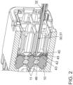
- the Figure 1 shows a connector 100 after fitting a collective seal 10 in the form of a mat seal 10 with an electrically conductive plug contact 30.
- the mat seal 10 has several through openings 11 for a plug contact 30 each, which can be fitted or left free as required.
- the mat seal 10 is housed together with a holding element 20 or a seal holding grid with an opening 21 for a connecting line 33 in a connector housing 50.
- the collective seals 10 are usually only fitted with relatively thin plug contacts 30 in the connectors 100 on the socket side (female). Thicker plug contacts 30 are used in the connectors 100 on the male side than on the socket side. When such thicker contact elements are passed through the mat seal 10, it may happen that the plug contacts 30 can damage the relatively soft mat seal 10, for example by piercing it.
- the invention provides a connector 100 which makes it possible to gently equip the collective seal 10 even in the case of a connector 100 on the plug side with relatively thick plug contacts 30 without damaging the collective seal 10.
- the invention provides a template 40 for the through-opening 11 in order to support the plug contact 30 when passing through the through-opening 11 of the collective seal 10.
- the template 40 can be designed in the form of a guide and/or centering foil.
- the guide foil is designed with a corresponding guide unit 41 for the respective through-opening 11 of the mat seal 10.
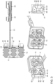
- the template 40 in particular the guide unit 41, can have a mapping guide geometry for the through-opening 11 (cf. the Figure 2 ).
- the guide geometry can be designed as a (3D) guide geometry with a specific depth t2 (cf. the Figure 4 ).
- the template 40 can be applied as a retrofit component for the connector 100, at least temporarily for equipping the mat seal 10 or permanently for the operation of the connector 100.
- the template 40 is arranged flat on one side of the collective seal 10 so that the respective guide unit 41 can at least partially penetrate into the corresponding through-opening 11 of the mat seal 10 (see the Figure 2 ).
- the template 40 only needs to be arranged loosely on the collective seal 10.
- the template 40 can no longer slip.
- the template 40 is positioned between the mat seal 10 and the holding element 20.
- the template 40 can also have a collar element 44 in order to at least partially enclose the holding element 20 in the area of the support surface on the template 40. The template 40 is thus reliably held in its position.
- a cover grille 51 or a locking plate is then placed in front of the other side of the connector 100.
- the cover grille 51 and/or the connector housing 50 in the area of the cover grille 51 can interact with a connector geometry 32 or with a so-called contact box on the plug contact 30 in a form-fitting and/or force-fitting manner in order to fasten the plug contact 30 to the connector 100.
- the template 40 helps in guiding the plug tip 31 through the through opening 11 of the collective seal 10 by precisely aligning the plug tip 31 with the aid of the guide unit 41 so that the plug tip 31 does not penetrate into the collective seal 10, but is guided specifically through the through opening 11 in the collective seal 10.
- the template 40 causes the plug contact 30 to be aligned with the guide unit 41 of the template 40 until the plug tip 31 exactly hits the through-opening 11 in the mat seal 10. The plug tip 31 can then be gently guided through the through-opening 11.
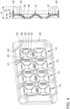
- the template 40 in the sense of the invention can also be formed for all through holes 11 of the collective seal 10 with a corresponding guide geometry, which can depict all through holes 11 of the collective seal 10 (cf. the Figure 4 ).
- the template 40 can have a guide unit 41 for each through-opening 11.
- the respective guide unit 41 can have a funnel-shaped guide geometry that can taper in the direction of the through-openings 11 of the collective seal 10.
- the guide unit 41 can have guide elements 42 in the form of flaps that can be opened in the direction of the through opening 11 of the collective seal 10.
- the guide elements 42 can preferably be attached to the respective guide unit 41 using hinge elements 45, in particular in the form of film hinges.
- the guide unit 41 can have a predetermined breaking geometry 43, for example between the flaps, in order to facilitate the passage of the plug tip 31.
- the guide unit 41 can have a complementary opening 46 for the through opening 11 at a lower point.
- the template 40 is unique within the scope of the invention.
- the template 40 can have a material thickness d of 0.1 mm to 0.2 mm, preferably 0.15 mm and a depth t1 of 1 mm to 1.2 mm, in particular 1.1 mm.
- the depth t2 of the funnel-shaped guide geometry can be in the range of 0.5 mm to 0.7 mm, preferably 0.6 mm.
Landscapes
- Engineering & Computer Science (AREA)
- Manufacturing & Machinery (AREA)
- Connector Housings Or Holding Contact Members (AREA)
Description
- Die Erfindung betrifft einen Steckverbinder zum Bereitstellen eines elektrischen Anschlusses an einem Geräteteil in einem Kraftfahrzeug, wie z.B. einem Türgriff, einem Motor- oder einem Airbagsteuergerät, nach dem Oberbegriff des unabhängigen Vorrichtungsanspruches. Ferner betrifft die Erfindung ein Verfahren zum Herstellen eines entsprechenden Steckverbinders nach dem Oberbegriff des unabhängigen Verfahrensanspruches.
- Bei Steckverbindern, die eine bauraumoptimierte Anordnung aufweisen, werden oft kombinierte Steckverbindungen, bspw. mithilfe von Sammeldichtungen in Form von Mattendichtungen, verwendet, um Bauraum für einzelne Leitungsisolationen unterschiedlicher Steckkontakte zu sparen. Solche Sammeldichtungen eignen sich zum Durchführen von relativ dünnen Steckkontakten in den Steckverbindern auf der Buchsenseite (weiblich). Bei den Steckverbindern auf der Stecherseite (männlich) werden dickere Steckkontakte verwendet als auf der Buchsenseite. Bei der Kontaktmontage werden die Kontaktelemente durch die Mattendichtung geschoben. Dabei besteht das Risiko, dass die Steckkontakte die relativ weiche Mattendichtung bei der Montage des Steckkontaktes beschädigen, bspw. durchstechen können. Aus diesem Grund werden Mattendichtungen bisher nur in Verbindung mit Steckverbindern an der Buchsenseite (weiblich) verwendet. Auf der Stecherseite werden die Steckkontakte zumeist einfach innerhalb eines Steckergehäuses mit einer Vergussmasse umspritzt. Das Umspritzen kann jedoch nur nach der finalen Montage aller Kontaktelemente im Steckergehäuse erfolgen. Dies schränkt jedoch die Montagefreiheit mit unterschiedlichen Steckkontakten bzw. mit einer unterschiedlichen Anzahl an Steckkontakten ein und schließt einen nachträglichen Umbau und/oder eine nachträgliche Wartung solcher Steckverbinder aus. Außerdem müssen die Stanzkanten der Steckkontakte zum Durchführen durch die Sammeldichtungen sorgfältig gratfrei gefertigt werden, um Beschädigungen der Dichtung bei der Kontaktmontage zu vermeiden, was mit einem erheblichen Herstellungsaufwand verbunden ist.
- Beispielhafte Steckverbinder sind aus den Schriften
EP 1 556 924 B1 ,WO 2015/121874 A1 ,JP 2003 092 165 A DE 196 41 408 A1 undEP 1 001 496 A2 bekannt. - Die Aufgabe der Erfindung ist es daher, mindestens einen aus dem Stand der Technik bekannten Nachteil bei einem Steckverbinder zumindest teilweise zu überwinden. Insbesondere ist es Aufgabe der Erfindung, einen Steckverbinder zum Bereitstellen eines elektrischen Anschlusses an einem Geräteteil in einem Kraftfahrzeug, wie z.B. einem Türgriff, einem Motor-oder einem Airbagsteuergerät, bereitzustellen, welcher einfach, kostengünstig und schnell in der Herstellung ist, welcher eine automatische Bestückung des Steckverbinders zulässt, welcher zuverlässig abgedichtet ist, welcher eine verlängerte Lebensdauer aufweist und welcher anpassungsfähig zusammengesetzt und/oder umgebaut sowie leicht gewartet werden kann.
- Die erfindungsgemäße Aufgabe wird durch einen Steckverbinder zum Bereitstellen eines elektrischen Anschlusses mit den Merkmalen des unabhängigen Vorrichtungsanspruches sowie durch ein Verfahren zum Herstellen eines entsprechenden Steckverbinders mit den Merkmalen des unabhängigen Verfahrensanspruches gelöst. In den abhängigen Ansprüchen sind bevorzugte Weiterbildungen der Erfindung aufgeführt.
- Die Erfindung stellt einen Steckverbinder zum Bereitstellen eines elektrischen Anschlusses, insbesondere an einem Geräteteil in einem Kraftfahrzeug, wie z.B. einem Türgriff, einem Motor-oder einem Airbagsteuergerät, bereit, aufweisend: eine Sammeldichtung bzw. eine Mattendichtung mit mindestens einer Durchgangsöffnung und mindestens einen elektrisch leitenden Steckkontakt, welcher durch die mindestens eine Durchgangsöffnung der Sammeldichtung durchführbar ist. Hierzu ist erfindungsgemäß vorgesehen, dass eine Schablone für die Durchgangsöffnung vorgesehen ist, um den Steckkontakt beim Durchführen durch die Durchgangsöffnung der Sammeldichtung zu unterstützen.
- Unter der Schablone im Sinne der Erfindung kann eine Führungs- und/oder Zentriervorrichtung, insbesondere eine Führungs- und/oder Zentrierfolie, mit einer korrespondierenden Führungseinheit für die Durchgangsöffnung verstanden werden. Die Schablone, insbesondere die Führungseinheit, kann wiederum eine abbildende Führungsgeometrie für die Durchgangsöffnung aufweisen. Die Führungsgeometrie kann vorzugsweise als eine (3D-)Führungsgeometrie mit einer bestimmten Tiefe ausgebildet sein. Die Schablone kann vorteilhafterweise folienartig ausgestaltet sein und flächig auf einer Seite der Sammeldichtung angeordnet sein. Durch die Auflage der Schablone auf einer Seite der Sammeldichtung kann die Führungsgeometrie zumindest zum Teil in die Durchgangsöffnung eindringen.
- Der erfindungsgemäße Steckverbinder eignet sich insbesondere als ein Geräte-Stecker, vorzugsweise auf der Stecherseite (männlich) bzw. auf der Geräteseite zweier komplementärer Steckverbindungen, der über relativ harte und/oder dicke Steckkontakte verfügen kann. Gleichwohl ist es aber auch denkbar, dass die Erfindung auch bei Steckverbindern auf der Buchsenseite (weiblich) vorteilhaft sein kann, um auch bei den Steckerbuchsen die Qualität und die Sicherheit zu erhöhen sowie deren Herstellung zu vereinfachen. Bei einem Steckkontakt im Sinne der Erfindung kann sowohl auf der Buchsenseite als auch auf der Stecherseite der Steckkontakt mit einer Anschlussleitung ausgebildet sein.
- Der Erfindungsgedanke liegt dabei darin, dass für die Herstellung des Steckverbinders eine Schablone für die Durchgangsöffnung bereitgestellt wird, die bei der Durchführung des Steckkontaktes die Spitze des Kontaktsteckers auf die Durchgangsöffnung der Sammeldichtung ausrichtet, sodass die Steckerspitze nicht in die Dichtung eindringt, sondern gezielt durch die Durchgangsöffnung in der Sammeldichtung geführt wird. Die Schablone bewirkt solange ein Ausrichten des Steckkontaktes entlang der Oberfläche der Schablone, vorzugsweise an einer Führungseinheit der Schablone, bis die Steckerspitze die Durchgangsöffnung in der Mattendichtung genau trifft und danach schonend durch diese Durchgangsöffnung geführt wird. Dies kann durch eine besondere Ausformung einer, bspw. trichterförmigen, Führungsgeometrie, die in die Durchgangsöffnung der Sammeldichtung zumindest zum Teil ragen kann, und/oder eine bestimmte Materialzusammensetzung, bspw. in Form einer elastischen Folie, der Schablone erreicht werden. Die Ausformung der Führungsgeometrie kann den Einfallswinkel der Steckerspitze auf die Oberfläche der Sammeldichtung beeinflussen, der ein Abgleiten entlang der Schablone anstatt eines Einstechens durch die Steckerspitze in das Material der Mattendichtung bewirken kann. Vorzugsweise kann die Schablone in Form einer elastischen Folie ausgebildet sein, die ein abgedämpftes Aufsetzen der Steckerspitze bewirken kann. Die Schablone kann dabei als ein Nachrüstbauteil für den Steckverbinder, zumindest vorübergehend oder dauerhaft, aufgebracht werden.
- Zumeist weisen Sammeldichtungen mehrere Durchgangsöffnungen auf, die nach Bedarf mit Steckkontakten bestückt werden können. Vorteilhafterweise kann die Schablone im Sinne der Erfindung für alle Durchgangsöffnungen der Sammeldichtung mit einer entsprechenden Führungsgeometrie ausgeformt sein. Mit anderen Worten kann die Schablone im Sinne der Erfindung eine Führungsgeometrie aufweisen, die alle Durchgangsöffnungen der Sammeldichtung abbildet. Ferner kann die Schablone jeweils eine Führungseinheit für jede Durchgangsöffnung aufweisen. Die jeweilige Führungseinheit kann eine trichterförmige Führungsgeometrie aufweisen, die sich in Richtung der Durchgangsöffnungen der Sammeldichtung verjüngt. Die Führungseinheit kann ferner an einer unteren Stelle eine komplementäre Öffnung für die Durchgangsöffnung aufweisen. Weiterhin ist es denkbar, dass die Führungseinheit sich in Richtung der Durchgangsöffnungen der Sammeldichtung öffenbare Klappen aufweisen kann. Zudem kann die Führungseinheit eine Sollbruchgeometrie, bspw. zwischen den Klappen, aufweisen, um einen Durchgang der Steckerspitze zu erleichtern.
- Somit wird ein Steckverbinder ermöglicht, welcher einfach, kostengünstig und schnell in Herstellung ist, welcher eine automatische Bestückung des Steckverbinders zulässt, welcher zuverlässig abgedichtet ist, welcher eine verlängerte Lebensdauer aufweist und welcher anpassungsfähig zusammengesetzt und/oder umgebaut sowie leicht gewartet werden kann.
- Ferner kann die Erfindung bei einem Steckverbinder vorsehen, dass die Schablone elastisch und/oder folienartig ausgebildet ist. Eine solche Schablone kann vorteilhafterweise abfedern und sich nachgiebig verformen, um den Steckkontakt auf eine vorteilhafte Weise ausrichten zu können. Außerdem kann eine solche Schablone eine dünne Materialstärke aufweisen und ohne wesentliche Bauraumverluste im Steckverbinder angeordnet werden.
- Weiterhin kann die Erfindung bei einem Steckverbinder vorsehen, dass die Schablone lose an der Sammeldichtung anliegt. Somit kann die Montage der Schablone innerhalb des Steckverbinders bzw. der Zusammenbau des Steckverbinders einfach und ohne großen Montageaufwand erfolgen.
- Im Rahmen der Erfindung ist es des Weiteren denkbar, dass die Schablone eine Materialstärke von 0,1 mm bis 0,2 mm, vorzugsweise 0,15 mm aufweisen kann. Somit kann eine dünne Schablone mit elastischen Eigenschaften bereitgestellt werden.
- Zudem ist es denkbar, dass die Schablone eine Tiefe von 1 mm bis 1,2 mm, insbesondere 1.1 mm aufweisen kann. Somit kann ein teilweises Eindringen einer Führungseinheit der Schablone in die jeweilige Durchgangsöffnung bewirkt werden, sodass die Steckerspitze präzise auf die Durchgangsöffnung der Sammeldichtung ausgerichtet werden kann.
- Außerdem kann die Erfindung bei einem Steckverbinder vorsehen, dass die Schablone mindestens eine Führungseinheit aufweist, um den Steckkontakt in Richtung zur Durchgangsöffnung auszurichten, wobei insbesondere die Führungseinheit eine trichterförmige Führungsgeometrie aufweisen kann. Vorzugsweise kann die trichterförmige Führungsgeometrie eine Tiefe von 0,5 mm bis 0,7 mm, vorzugsweise 0,6 mm aufweisen. Somit kann die Schablone eine abbildende Führungsgeometrie für die Durchgangsöffnung bereitstellen. Die Führungseinheit sorgt vorteilhafterweise dafür, dass die Steckerspitze beim Bestücken der Sammeldichtung zuerst auf die Schablone auftritt und durch die Führungseinheit auf die Durchgangsöffnung ausgerichtet wird, bevor es durch die Durchgangsöffnung geführt wird.
- Somit kann vermieden werden, dass die Steckerspitze in die Sammeldichtung einsticht.
- Ferner weist die Schablone gemäß der Erfindung aufklappbare Führungselemente auf, die in der Durchgangsöffnung der Sammeldichtung durch den Steckkontakt öffenbar sind. Somit kann die Ausrichtung der Steckerspitze erheblich vereinfacht werden und ein beinahe reibungsloses Durchführen der Steckerspitze durch die Durchgangsöffnung ermöglicht werden. Die Führungselemente können vorzugsweise mithilfe von Scharnierelementen an der jeweiligen Führungseinheit befestigt werden.
- Weiterhin sieht die Erfindung bei dem Steckverbinder vor, dass die Schablone zwischen den aufklappbaren Führungselementen eine Sollbruchgeometrie aufweist, die durch den Steckkontakt in Richtung zur Durchgangsöffnung öffenbar ist. Zudem kann die Schablone eine komplementäre Öffnung für die Durchgangsöffnung aufweisen. Die Sollbruchgeometrie sorgt vorteilhafterweise dafür, dass nach dem Ausrichten der Steckerspitze, ein störungsfreies Durchführen der Steckerspitze durch die Durchgangsöffnung ermöglicht werden kann.
- Des Weiteren kann die Schablone im Rahmen der Erfindung ein Kragenelement aufweisen, welches zum Positionieren eines Halteelementes bzw. eines Dichtungshaltegitters für die Schablone an einem Steckergehäuse dienen kann. Das Kragenelement kann die Schablone schalenförmig umranden, sodass innerhalb der Schablone eine Aufnahme für das Halteelement geschaffen wird. Durch Anbringen des Halteelementes kann zugleich die Schablone verliersicher an der Sammeldichtung angeordnet werden. Die Schablone wird somit zwischen der Sammeldichtung und dem Halteelement angeordnet. Das Kragenelement kann den Fuß des Halteelementes im Bereich der Auflagefläche auf der Schablone umranden.
- Ferner wird die erfindungsgemäße Aufgabe durch ein Verfahren zum Herstellen eines Steckverbinders gelöst, aufweisend: eine Sammeldichtung mit mindestens einer Durchgangsöffnung und mindestens einen elektrisch leitenden Steckkontakt, welcher durch die mindestens eine Durchgangsöffnung der Sammeldichtung durchgeführt wird. Hierzu ist es erfindungsgemäß vorgesehen, dass beim Durchführen des Steckkontaktes durch die Durchgangsöffnung der Sammeldichtung eine Schablone verwendet wird, um den Steckkontakt durch die Durchgangsöffnung der Sammeldichtung gezielt zu führen. Mithilfe des erfindungsgemäßen Verfahrens werden die gleichen Vorteile erreicht, die oben im Zusammenhang mit dem erfindungsgemäßen Steckverbinder beschrieben wurden. Zur Vermeidung von Wiederholungen wird vorliegend vollumfänglich darauf Bezug genommen.
- Weiterhin kann das Verfahren vorsehen, dass die Schablone nach dem Durchführen des Steckkontaktes durch die Durchgangsöffnung der Sammeldichtung im Normalbetrieb des Steckverbinders an der Sammeldichtung verbleibt. Somit kann die Inbetriebnahme des Steckverbinders beschleunigt werden.
- Weitere, die Erfindung verbessernde Maßnahmen werden nachstehend mit der Beschreibung der bevorzugten Ausführungsbeispiele der Erfindung anhand der Figuren näher dargestellt. Dabei können die in den Ansprüchen und in der Beschreibung erwähnten Merkmale jeweils einzeln für sich oder in beliebiger Kombination erfindungswesentlich sein. Dabei ist zu beachten, dass die Figuren nur einen beschreibenden Charakter haben und nicht dazu gedacht sind, die Erfindung in irgendeiner Form einzuschränken. Es zeigen:
- Fig. 1
- eine Schnittdarstellung sowie unterschiedliche Ansichten eines zusammengebauten Steckverbinders nach dem Bestücken einer Sammeldichtung mit einem Steckkontakt,
- Fig. 2
- eine vergrößerte Darstellung eines Steckkontaktes beim Durchführen durch eine Schablone im Sinne der Erfindung,
- Fig. 3
- unterschiedliche Ansichten auf einen Steckkontakt nach dem Durchführen durch eine Schablone im Sinne der Erfindung, und
- Fig. 4
- unterschiedliche Ansichten auf eine Schablone im Sinne der Erfindung.
- In den nachfolgenden Figuren werden für die gleichen technischen Merkmale auch von unterschiedlichen Ausführungsbeispielen die identischen Bezugszeichen verwendet.
- Die
Figur 1 zeigt einen Steckverbinder 100 nach dem Bestücken einer Sammeldichtung 10 in Form einer Mattendichtung 10 mit einem elektrisch leitenden Steckkontakt 30. Die Mattendichtung 10 weist mehrere Durchgangsöffnungen 11 für jeweils einen Steckkontakt 30 auf, die nach Bedarf bestück oder frei gelassen werden können. Zusammen wird die Mattendichtung 10 mit einem Halteelement 20 bzw. ein Dichtungshaltegitter mit einer Öffnung 21 für eine Anschlussleitung 33 in einem Steckergehäuse 50 untergebracht. - Die Sammeldichtungen 10 werden herkömmlicherweise nur mit relativ dünnen Steckkontakten 30 in den Steckverbindern 100 auf der Buchsenseite (weiblich) bestückt. Bei den Steckverbindern 100 auf der Stecherseite (männlich) werden dickere Steckkontakte 30 verwendet als auf der Buchsenseite. Beim Durchführen solcher dickerer Kontaktelemente durch die Mattendichtung 10 kann es vorkommen, dass die Steckkontakte 30 die relativ weiche Mattendichtung 10 beschädigen, bspw. durchstechen können.
- Die Erfindung stellt einen Steckverbinder 100 bereit, der es ermöglicht, die Sammeldichtung 10 auch bei einem Steckverbinder 100 auf der Stecherseite mit relativ dicken Steckkontakten 30 schonend zu bestücken, ohne die Sammeldichtung 10 zu beschädigen.
- Die Erfindung sieht hierzu eine Schablone 40 für die Durchgangsöffnung 11 vor, um den Steckkontakt 30 beim Durchführen durch die Durchgangsöffnung 11 der Sammeldichtung 10 zu unterstützen.
- Wie es in der
Figur 1 zu erkennen ist, kann die Schablone 40 in Form einer Führungs- und/oder Zentrierfolie ausgebildet sein. Die Führungsfolie ist mit jeweils einer korrespondierenden Führungseinheit 41 für die jeweilige Durchgangsöffnung 11 der Mattendichtung 10 ausgeführt. Die Schablone 40, insbesondere die Führungseinheit 41, kann eine abbildende Führungsgeometrie für die Durchgangsöffnung 11 aufweisen (vgl. dieFigur 2 ). Die Führungsgeometrie kann im Rahmen der Erfindung als eine (3D-)Führungsgeometrie mit einer bestimmten Tiefe t2 ausgebildet sein (vgl. dieFigur 4 ). Die Schablone 40 kann dabei als ein Nachrüstbauteil für den Steckverbinder 100, zumindest vorübergehend zum Bestücken der Mattendichtung 10 oder dauerhaft für den Betrieb des Steckverbinders 100, aufgebracht werden. - Wie es in den
Figuren 1 bis 3 zu erkennen ist, wird die Schablone 40 flächig auf einer Seite der Sammeldichtung 10 angeordnet, sodass die jeweilige Führungseinheit 41 zumindest zum Teil in die korrespondierende Durchgangsöffnung 11 der Mattendichtung 10 eindringen kann (vgl. dieFigur 2 ). Die Schablone 40 braucht lediglich lose auf der Sammeldichtung 10 angeordnet werden. Wenn das Halteelement 20 auf der Schablone 40 positioniert wird, kann die Schablone 40 nicht mehr verrutschen. Die Schablone 40 wird mit anderen Worten zwischen der Mattendichtung 10 und dem Halteelement 20 positioniert. Die Schablone 40 kann ferner ein Kragenelement 44 aufweisen, um das Halteelement 20 im Bereich der Auflagefläche auf der Schablone 40 zumindest zum Teil zu umschließen. Somit wird die Schablone 40 zuverlässig in ihrer Position gehalten. - Anschließend wird ein Abschlussgitter 51 bzw. eine Verriegelungsplatte vor der anderen Seite des Steckverbinders 100 aufgesetzt. Das Abschlussgitter 51 und/oder das Steckergehäuse 50 im Bereich des Abschlussgitters 51 kann mit einer Steckergeometrie 32 bzw. mit einem sog. Kontaktkasten am Steckkontakt 30 form- und/oder kraftschlüssig zusammenwirken, um den Steckkontakt 30 am Steckverbinder 100 zu befestigen.
- Wie es die
Figur 2 zeigt, hilft die erfindungsgemäße Schablone 40 bei der Durchführung der Steckerspitze 31 durch die Durchgangsöffnung 11 der Sammeldichtung 10, indem sie mithilfe der Führungseinheit 41 die Steckerspitze 31 genau ausrichtet, damit die Steckerspitze 31 nicht in die Sammeldichtung 10 eindringt, sondern gezielt durch die Durchgangsöffnung 11 in der Sammeldichtung 10 geführt wird. - Wie es die
Figur 2 ferner zeigt, bewirkt die Schablone 40 solange ein Ausrichten des Steckkontaktes 30 an der Führungseinheit 41 der Schablone 40, bis die Steckerspitze 31 die Durchgangsöffnung 11 in der Mattendichtung 10 genau trifft. Danach kann die Steckerspitze 31 schonend durch die Durchgangsöffnung 11 geführt werden. - Da die Sammeldichtungen 10 zumeist mehrere Durchgangsöffnungen 11 aufweisen, die nach Bedarf mit Steckkontakten 30 bestückt werden, kann auch die Schablone 40 im Sinne der Erfindung für alle Durchgangsöffnungen 11 der Sammeldichtung 10 mit einer entsprechenden Führungsgeometrie ausgeformt sein, die alle Durchgangsöffnungen 11 der Sammeldichtung 10 abbilden kann (vgl. die
Figur 4 ). Im Rahmen der Erfindung kann die Schablone 40 jeweils eine Führungseinheit 41 für jede Durchgangsöffnung 11 aufweisen. Die jeweilige Führungseinheit 41 kann eine trichterförmige Führungsgeometrie aufweisen, die sich in Richtung der Durchgangsöffnungen 11 der Sammeldichtung 10 verjüngen kann. - Wie es die
Figur 3 zeigt, kann die Führungseinheit 41 sich in Richtung der Durchgangsöffnung 11 der Sammeldichtung 10 öffenbare Führungselemente 42 in Form von Klappen aufweisen. Die Führungselemente 42 können vorzugsweise mithilfe von Scharnierelementen 45, insbesondere in Form von Filmscharnieren, an der jeweiligen Führungseinheit 41 befestigt werden. Zudem kann die Führungseinheit 41 eine Sollbruchgeometrie 43, bspw. zwischen den Klappen, aufweisen, um einen Durchgang der Steckerspitze 31 zu erleichtern. Zudem oder stattdessen kann die Führungseinheit 41 an einer unteren Stelle eine komplementäre Öffnung 46 für die Durchgangsöffnung 11 aufweisen. - Ferner zeigt die
Figur 4 die Schablone 40 im Rahmen der Erfindung in Alleinstellung. Die Schablone 40 kann eine Materialstärke d von 0,1 mm bis 0,2 mm, vorzugsweise 0,15 mm und eine Tiefe t1 von 1 mm bis 1,2 mm, insbesondere 1,1 mm aufweisen. Die Tiefe t2 der trichterförmigen Führungsgeometrie kann im Bereich von 0,5 mm bis 0,7 mm liegen, vorzugsweise 0,6 mm betragen. - Die voranstehende Beschreibung der Figuren beschreibt die vorliegende Erfindung ausschließlich im Rahmen von Beispielen.
-
- 10
- Sammeldichtung, Mattendichtung
- 11
- Durchgangsöffnung
- 20
- Halteelement
- 21
- Öffnung
- 30
- Steckkontakt
- 31
- Steckerspitze
- 32
- Steckergeometrie
- 33
- Anschlussleitung
- 40
- Schablone
- 41
- Führungseinheit
- 42
- Führungselement
- 43
- Sollbruchgeometrie
- 44
- Kragenelement
- 45
- Scharnierelement
- 46
- komplementäre Öffnung
- 50
- Steckergehäuse
- 51
- Abschlussgitter
- 100
- Steckverbinder
- d
- Materialstärke
- t1
- Tiefe
- t2
- Tiefe
Claims (9)
- Steckverbinder (100) zum Bereitstellen eines elektrischen Anschlusses, aufweisend:eine Sammeldichtung (10) mit mindestens einer Durchgangsöffnung (11) und mindestens einen elektrisch leitenden Steckkontakt (30),welcher durch die mindestens eine Durchgangsöffnung (11) der Sammeldichtung (10) durchführbar ist,wobei eine Schablone (40) für die Durchgangsöffnung (11) vorgesehen ist, um den Steckkontakt (30) beim Durchführen durch die Durchgangsöffnung (11) der Sammeldichtung (10) zu unterstützen,wobei die Schablone (40) aufklappbare Führungselemente (42) aufweist, die in der Durchgangsöffnung (11) der Sammeldichtung (10) durch den Steckkontakt (30) öffenbar sind,dadurch gekennzeichnet,dass die Schablone (40) zwischen den aufklappbaren Führungselementen (42) eine Sollbruchgeometrie (43) aufweist, die durch den Steckkontakt (30) in Richtung zur Durchgangsöffnung (11) öffenbar ist.
- Steckverbinder (100) nach Anspruch 1,
dadurch gekennzeichnet,
dass die Schablone (40) elastisch und/oder folienartig ausgebildet ist. - Steckverbinder (100) nach Anspruch 1,
dadurch gekennzeichnet,
dass die Schablone (40) lose an der Sammeldichtung (10) anliegt. - Steckverbinder (100) nach einem der vorhergehenden Ansprüche,
dadurch gekennzeichnet,dass die Schablone (40) eine Materialstärke (d) von 0,1 mm bis 0,2 mm, vorzugsweise 0,15 mm aufweist,und/oder dass die Schablone (40) eine Tiefe (t1) von 1 mm bis 1,2 mm, insbesondere 1,1 mm aufweist. - Steckverbinder (100) nach einem der vorhergehenden Ansprüche,
dadurch gekennzeichnet,dass die Schablone (40) mindestens eine Führungseinheit (41) aufweist, um den Steckkontakt (30) in Richtung zur Durchgangsöffnung (11) auszurichten,und/oder dass die Führungseinheit (41) eine trichterförmige Führungsgeometrie aufweist,und/oder dass die trichterförmige Führungsgeometrie eine Tiefe (t2) von 0,5 mm bis 0,7 mm, vorzugsweise 0,6 mm aufweist. - Steckverbinder (100) nach dem vorhergehenden Anspruch,
dadurch gekennzeichnet,
dass die Führungselemente (42) mithilfe von Scharnierelementen (45) an der jeweiligen Führungseinheit (41) befestigt sind. - Steckverbinder (100) nach einem der vorhergehenden Ansprüche,
dadurch gekennzeichnet,
dass die Schablone (40) ein Kragenelement (44) aufweist, welches zum Positionieren eines Halteelementes (20) für die Schablone (40) an einem Steckergehäuse (50)dient. - Verfahren zum Herstellen eines Steckverbinders (100), aufweisend:eine Sammeldichtung (10) mit mindestens einer Durchgangsöffnung (11) und mindestens einen elektrisch leitenden Steckkontakt (30),welcher durch die mindestens eine Durchgangsöffnung (11) der Sammeldichtung (10) durchgeführt wird,wobei beim Durchführen des Steckkontaktes (30) durch die Durchgangsöffnung (11) der Sammeldichtung (10) eine Schablone (40) verwendet wird, um den Steckkontakt (30) durch die Durchgangsöffnung (11) der Sammeldichtung (10) gezielt zu führen, wobei die Schablone (40) aufklappbare Führungselemente (42) aufweist, die in der Durchgangsöffnung (11) der Sammeldichtung (10) durch den Steckkontakt (30) geöffnet werden,dadurch gekennzeichnet,dass die Schablone (40) zwischen den aufklappbaren Führungselementen (42) eine Sollbruchgeometrie (43) aufweist, die durch den Steckkontakt (30) in Richtung zur Durchgangsöffnung (11) geöffnet werden.
- Verfahren nach dem vorhergehenden Anspruch,
dadurch gekennzeichnet,
dass die Schablone (40) nach dem Durchführen des Steckkontaktes (30) durch die Durchgangsöffnung (11) der Sammeldichtung (10) im Normalbetrieb des Steckverbinders (100) an der Sammeldichtung (10) verbleibt.
Applications Claiming Priority (2)
| Application Number | Priority Date | Filing Date | Title |
|---|---|---|---|
| DE102018120104.4A DE102018120104B4 (de) | 2018-08-17 | 2018-08-17 | Steckverbinder zum Bereitstellen eines elektrischen Anschlusses und Verfahren |
| PCT/EP2019/071941 WO2020035566A1 (de) | 2018-08-17 | 2019-08-15 | Steckverbinder |
Publications (2)
| Publication Number | Publication Date |
|---|---|
| EP3837740A1 EP3837740A1 (de) | 2021-06-23 |
| EP3837740B1 true EP3837740B1 (de) | 2024-10-09 |
Family
ID=67660562
Family Applications (1)
| Application Number | Title | Priority Date | Filing Date |
|---|---|---|---|
| EP19755604.6A Active EP3837740B1 (de) | 2018-08-17 | 2019-08-15 | Steckverbinder |
Country Status (5)
| Country | Link |
|---|---|
| US (1) | US11539159B2 (de) |
| EP (1) | EP3837740B1 (de) |
| CN (1) | CN113169477B (de) |
| DE (1) | DE102018120104B4 (de) |
| WO (1) | WO2020035566A1 (de) |
Families Citing this family (1)
| Publication number | Priority date | Publication date | Assignee | Title |
|---|---|---|---|---|
| DE102020133319A1 (de) * | 2020-12-14 | 2022-06-15 | Lear Corporation | Elektrische Steckverbinder mit verjüngten Anschlussdurchgängen |
Citations (1)
| Publication number | Priority date | Publication date | Assignee | Title |
|---|---|---|---|---|
| EP1001496A2 (de) * | 1998-11-13 | 2000-05-17 | Framatome Connectors International | Elektrischer Steckverbinder |
Family Cites Families (20)
| Publication number | Priority date | Publication date | Assignee | Title |
|---|---|---|---|---|
| JP2921641B2 (ja) * | 1994-05-23 | 1999-07-19 | 矢崎総業株式会社 | 防水コネクタ |
| JPH09106851A (ja) | 1995-10-09 | 1997-04-22 | Yazaki Corp | 防水コネクタ |
| JPH09289057A (ja) * | 1996-04-19 | 1997-11-04 | Yazaki Corp | 防水コネクタ |
| JP3547988B2 (ja) * | 1998-03-31 | 2004-07-28 | 矢崎総業株式会社 | 防水コネクタ及び防水処理方法 |
| JP3380528B2 (ja) * | 2000-07-13 | 2003-02-24 | 日本圧着端子製造株式会社 | 防水コネクタ |
| JP2002122524A (ja) | 2000-10-13 | 2002-04-26 | Sumitomo Metal Mining Co Ltd | 透過電子顕微鏡用試料の作製方法 |
| JP2002164143A (ja) * | 2000-11-27 | 2002-06-07 | Sumitomo Wiring Syst Ltd | 防水コネクタにおける端子金具の挿抜方法及びこれに使用する治具 |
| JP2003092165A (ja) * | 2001-09-18 | 2003-03-28 | Sumitomo Wiring Syst Ltd | 防水コネクタ |
| DE10300264A1 (de) * | 2003-01-08 | 2004-08-19 | Delphi Technologies, Inc., Troy | Blockdichtungssystem |
| EP1555728B1 (de) * | 2004-01-16 | 2007-03-14 | Delphi Technologies, Inc. | Elektrischer Verbinder |
| JP5203094B2 (ja) * | 2008-04-03 | 2013-06-05 | 矢崎総業株式会社 | コネクタ用パッキン構造 |
| DE102011006836A1 (de) * | 2011-04-06 | 2012-10-11 | Robert Bosch Gmbh | Steckverbinder mit Einführhilfe zum Einführen von Kontaktelementen |
| US8969741B2 (en) * | 2011-06-10 | 2015-03-03 | Cooper Technologies Company | Damming device for cable sealing |
| DE102011080347A1 (de) | 2011-08-03 | 2013-02-07 | Robert Bosch Gmbh | Geschlossene Dichtmatte |
| JP2013073719A (ja) * | 2011-09-27 | 2013-04-22 | Sumitomo Wiring Syst Ltd | コネクタ |
| JP2014017171A (ja) * | 2012-07-10 | 2014-01-30 | Sumitomo Wiring Syst Ltd | 防水コネクタ |
| DE102012223431A1 (de) * | 2012-12-17 | 2014-06-18 | Robert Bosch Gmbh | Gehäuse für eine elektrische Maschine mit einer Dichtung |
| WO2015121874A1 (en) * | 2014-02-11 | 2015-08-20 | Tyco Electronics Amp Gmbh | Cover for a connector housing and connector housing having such cover |
| JP6370210B2 (ja) * | 2014-12-24 | 2018-08-08 | 住友電装株式会社 | 防水コネクタ |
| US9960523B2 (en) * | 2015-04-22 | 2018-05-01 | Yazaki Corporation | Mat seal cover of waterproof connector |
-
2018
- 2018-08-17 DE DE102018120104.4A patent/DE102018120104B4/de active Active
-
2019
- 2019-08-15 WO PCT/EP2019/071941 patent/WO2020035566A1/de not_active Ceased
- 2019-08-15 CN CN201980068482.5A patent/CN113169477B/zh active Active
- 2019-08-15 EP EP19755604.6A patent/EP3837740B1/de active Active
- 2019-08-15 US US17/268,610 patent/US11539159B2/en active Active
Patent Citations (1)
| Publication number | Priority date | Publication date | Assignee | Title |
|---|---|---|---|---|
| EP1001496A2 (de) * | 1998-11-13 | 2000-05-17 | Framatome Connectors International | Elektrischer Steckverbinder |
Also Published As
| Publication number | Publication date |
|---|---|
| EP3837740A1 (de) | 2021-06-23 |
| CN113169477A (zh) | 2021-07-23 |
| DE102018120104B4 (de) | 2025-06-12 |
| US20210242621A1 (en) | 2021-08-05 |
| WO2020035566A1 (de) | 2020-02-20 |
| US11539159B2 (en) | 2022-12-27 |
| DE102018120104A1 (de) | 2020-02-20 |
| CN113169477B (zh) | 2023-09-05 |
Similar Documents
| Publication | Publication Date | Title |
|---|---|---|
| EP3235060B1 (de) | Steckverbinder | |
| DE102009025113A1 (de) | Einpresskontakt zur Verbindung eines elektronischen Bauelementes mit einer Leiterplatte sowie Einpresswerkzeug | |
| EP3224907B1 (de) | Steckverbinder für flexible leiterfolien | |
| DE202014106058U1 (de) | Steckverbinder | |
| DE112010004634T5 (de) | Draht-Halter | |
| WO2006108534A1 (de) | Vorrichtung und verfahren zur universellen kabeldurchführung | |
| WO2016096253A1 (de) | Sensoreinrichtung, insbesondere für die verwendung in einem kraftfahrzeug | |
| DE102013211455A1 (de) | Sekundärverriegelung für einen Stecker | |
| DE102007009644A1 (de) | Elektronische Baugruppe mit Steckverbindung | |
| DE102017108320A1 (de) | Flachteilhalter für die Befestigung eines Flachteils an einem Rahmengestell eines Schaltschranks und ein entsprechender Schaltschrank | |
| EP4029132B1 (de) | Elektrische antriebseinrichtung und antriebsanordnung | |
| EP3837740B1 (de) | Steckverbinder | |
| EP2337161B1 (de) | Steckeranordnung und Abdichteinrichtung für wenigstens eine, insbesondere elektrische Leitung | |
| EP3729564B1 (de) | Steckverbinder | |
| EP2169776A1 (de) | Elektrische Steckverbindung | |
| DE102013209435A1 (de) | Steckerverbindung mit einem zur Vermeidung von Spänen optimierten Führungselement | |
| DE102006022382A1 (de) | Vorrichtung und Verfahren zur Befestigung eines Wischermotors an ein Wischergestänge | |
| DE102020111030A1 (de) | Kontaktanordnung | |
| EP3946994B1 (de) | Verfahren zum herstellen einer toleranzausgeglichenen verbindung zwischen einem ersten bauteil und einem zweiten bauteil und elektrischer antrieb | |
| DE102009041393A1 (de) | Befestigungsanordnung | |
| EP2018693B1 (de) | Stromprofil für kabeldurchführungen | |
| EP1986281B1 (de) | Verfahren zur Herstellung einer elektrisch leitenden Verbindung | |
| DE102012108859B4 (de) | Elektronikmodul | |
| DE102020131254A1 (de) | Plattenaufbauten zur durchführung elektrischer leiter | |
| DE10316384A1 (de) | Kontaktadapter für die Kontaktierung einer Antennenstruktur eines Fahrzeuges |
Legal Events
| Date | Code | Title | Description |
|---|---|---|---|
| STAA | Information on the status of an ep patent application or granted ep patent |
Free format text: STATUS: UNKNOWN |
|
| STAA | Information on the status of an ep patent application or granted ep patent |
Free format text: STATUS: THE INTERNATIONAL PUBLICATION HAS BEEN MADE |
|
| PUAI | Public reference made under article 153(3) epc to a published international application that has entered the european phase |
Free format text: ORIGINAL CODE: 0009012 |
|
| STAA | Information on the status of an ep patent application or granted ep patent |
Free format text: STATUS: REQUEST FOR EXAMINATION WAS MADE |
|
| 17P | Request for examination filed |
Effective date: 20210309 |
|
| AK | Designated contracting states |
Kind code of ref document: A1 Designated state(s): AL AT BE BG CH CY CZ DE DK EE ES FI FR GB GR HR HU IE IS IT LI LT LU LV MC MK MT NL NO PL PT RO RS SE SI SK SM TR |
|
| DAV | Request for validation of the european patent (deleted) | ||
| DAX | Request for extension of the european patent (deleted) | ||
| STAA | Information on the status of an ep patent application or granted ep patent |
Free format text: STATUS: EXAMINATION IS IN PROGRESS |
|
| 17Q | First examination report despatched |
Effective date: 20220928 |
|
| GRAP | Despatch of communication of intention to grant a patent |
Free format text: ORIGINAL CODE: EPIDOSNIGR1 |
|
| STAA | Information on the status of an ep patent application or granted ep patent |
Free format text: STATUS: GRANT OF PATENT IS INTENDED |
|
| INTG | Intention to grant announced |
Effective date: 20240529 |
|
| GRAS | Grant fee paid |
Free format text: ORIGINAL CODE: EPIDOSNIGR3 |
|
| GRAA | (expected) grant |
Free format text: ORIGINAL CODE: 0009210 |
|
| STAA | Information on the status of an ep patent application or granted ep patent |
Free format text: STATUS: THE PATENT HAS BEEN GRANTED |
|
| AK | Designated contracting states |
Kind code of ref document: B1 Designated state(s): AL AT BE BG CH CY CZ DE DK EE ES FI FR GB GR HR HU IE IS IT LI LT LU LV MC MK MT NL NO PL PT RO RS SE SI SK SM TR |
|
| REG | Reference to a national code |
Ref country code: CH Ref legal event code: EP |
|
| REG | Reference to a national code |
Ref country code: DE Ref legal event code: R096 Ref document number: 502019012277 Country of ref document: DE |
|
| REG | Reference to a national code |
Ref country code: IE Ref legal event code: FG4D Free format text: LANGUAGE OF EP DOCUMENT: GERMAN |
|
| P01 | Opt-out of the competence of the unified patent court (upc) registered |
Free format text: CASE NUMBER: APP_53748/2024 Effective date: 20240927 |
|
| REG | Reference to a national code |
Ref country code: LT Ref legal event code: MG9D |
|
| REG | Reference to a national code |
Ref country code: NL Ref legal event code: MP Effective date: 20241009 |
|
| PG25 | Lapsed in a contracting state [announced via postgrant information from national office to epo] |
Ref country code: NL Free format text: LAPSE BECAUSE OF FAILURE TO SUBMIT A TRANSLATION OF THE DESCRIPTION OR TO PAY THE FEE WITHIN THE PRESCRIBED TIME-LIMIT Effective date: 20241009 |
|
| PG25 | Lapsed in a contracting state [announced via postgrant information from national office to epo] |
Ref country code: NL Free format text: LAPSE BECAUSE OF FAILURE TO SUBMIT A TRANSLATION OF THE DESCRIPTION OR TO PAY THE FEE WITHIN THE PRESCRIBED TIME-LIMIT Effective date: 20241009 |
|
| PG25 | Lapsed in a contracting state [announced via postgrant information from national office to epo] |
Ref country code: IS Free format text: LAPSE BECAUSE OF FAILURE TO SUBMIT A TRANSLATION OF THE DESCRIPTION OR TO PAY THE FEE WITHIN THE PRESCRIBED TIME-LIMIT Effective date: 20250209 Ref country code: HR Free format text: LAPSE BECAUSE OF FAILURE TO SUBMIT A TRANSLATION OF THE DESCRIPTION OR TO PAY THE FEE WITHIN THE PRESCRIBED TIME-LIMIT Effective date: 20241009 Ref country code: PT Free format text: LAPSE BECAUSE OF FAILURE TO SUBMIT A TRANSLATION OF THE DESCRIPTION OR TO PAY THE FEE WITHIN THE PRESCRIBED TIME-LIMIT Effective date: 20250210 |
|
| PG25 | Lapsed in a contracting state [announced via postgrant information from national office to epo] |
Ref country code: FI Free format text: LAPSE BECAUSE OF FAILURE TO SUBMIT A TRANSLATION OF THE DESCRIPTION OR TO PAY THE FEE WITHIN THE PRESCRIBED TIME-LIMIT Effective date: 20241009 |
|
| PG25 | Lapsed in a contracting state [announced via postgrant information from national office to epo] |
Ref country code: BG Free format text: LAPSE BECAUSE OF FAILURE TO SUBMIT A TRANSLATION OF THE DESCRIPTION OR TO PAY THE FEE WITHIN THE PRESCRIBED TIME-LIMIT Effective date: 20241009 |
|
| PG25 | Lapsed in a contracting state [announced via postgrant information from national office to epo] |
Ref country code: ES Free format text: LAPSE BECAUSE OF FAILURE TO SUBMIT A TRANSLATION OF THE DESCRIPTION OR TO PAY THE FEE WITHIN THE PRESCRIBED TIME-LIMIT Effective date: 20241009 |
|
| PG25 | Lapsed in a contracting state [announced via postgrant information from national office to epo] |
Ref country code: NO Free format text: LAPSE BECAUSE OF FAILURE TO SUBMIT A TRANSLATION OF THE DESCRIPTION OR TO PAY THE FEE WITHIN THE PRESCRIBED TIME-LIMIT Effective date: 20250109 |
|
| PG25 | Lapsed in a contracting state [announced via postgrant information from national office to epo] |
Ref country code: LV Free format text: LAPSE BECAUSE OF FAILURE TO SUBMIT A TRANSLATION OF THE DESCRIPTION OR TO PAY THE FEE WITHIN THE PRESCRIBED TIME-LIMIT Effective date: 20241009 Ref country code: GR Free format text: LAPSE BECAUSE OF FAILURE TO SUBMIT A TRANSLATION OF THE DESCRIPTION OR TO PAY THE FEE WITHIN THE PRESCRIBED TIME-LIMIT Effective date: 20250110 |
|
| PG25 | Lapsed in a contracting state [announced via postgrant information from national office to epo] |
Ref country code: PL Free format text: LAPSE BECAUSE OF FAILURE TO SUBMIT A TRANSLATION OF THE DESCRIPTION OR TO PAY THE FEE WITHIN THE PRESCRIBED TIME-LIMIT Effective date: 20241009 |
|
| PG25 | Lapsed in a contracting state [announced via postgrant information from national office to epo] |
Ref country code: RS Free format text: LAPSE BECAUSE OF FAILURE TO SUBMIT A TRANSLATION OF THE DESCRIPTION OR TO PAY THE FEE WITHIN THE PRESCRIBED TIME-LIMIT Effective date: 20250109 |
|
| PG25 | Lapsed in a contracting state [announced via postgrant information from national office to epo] |
Ref country code: SM Free format text: LAPSE BECAUSE OF FAILURE TO SUBMIT A TRANSLATION OF THE DESCRIPTION OR TO PAY THE FEE WITHIN THE PRESCRIBED TIME-LIMIT Effective date: 20241009 |
|
| PG25 | Lapsed in a contracting state [announced via postgrant information from national office to epo] |
Ref country code: DK Free format text: LAPSE BECAUSE OF FAILURE TO SUBMIT A TRANSLATION OF THE DESCRIPTION OR TO PAY THE FEE WITHIN THE PRESCRIBED TIME-LIMIT Effective date: 20241009 |
|
| REG | Reference to a national code |
Ref country code: DE Ref legal event code: R097 Ref document number: 502019012277 Country of ref document: DE |
|
| PG25 | Lapsed in a contracting state [announced via postgrant information from national office to epo] |
Ref country code: EE Free format text: LAPSE BECAUSE OF FAILURE TO SUBMIT A TRANSLATION OF THE DESCRIPTION OR TO PAY THE FEE WITHIN THE PRESCRIBED TIME-LIMIT Effective date: 20241009 |
|
| PG25 | Lapsed in a contracting state [announced via postgrant information from national office to epo] |
Ref country code: RO Free format text: LAPSE BECAUSE OF FAILURE TO SUBMIT A TRANSLATION OF THE DESCRIPTION OR TO PAY THE FEE WITHIN THE PRESCRIBED TIME-LIMIT Effective date: 20241009 |
|
| PG25 | Lapsed in a contracting state [announced via postgrant information from national office to epo] |
Ref country code: SK Free format text: LAPSE BECAUSE OF FAILURE TO SUBMIT A TRANSLATION OF THE DESCRIPTION OR TO PAY THE FEE WITHIN THE PRESCRIBED TIME-LIMIT Effective date: 20241009 |
|
| PG25 | Lapsed in a contracting state [announced via postgrant information from national office to epo] |
Ref country code: CZ Free format text: LAPSE BECAUSE OF FAILURE TO SUBMIT A TRANSLATION OF THE DESCRIPTION OR TO PAY THE FEE WITHIN THE PRESCRIBED TIME-LIMIT Effective date: 20241009 |
|
| PG25 | Lapsed in a contracting state [announced via postgrant information from national office to epo] |
Ref country code: IT Free format text: LAPSE BECAUSE OF FAILURE TO SUBMIT A TRANSLATION OF THE DESCRIPTION OR TO PAY THE FEE WITHIN THE PRESCRIBED TIME-LIMIT Effective date: 20241009 |
|
| PLBE | No opposition filed within time limit |
Free format text: ORIGINAL CODE: 0009261 |
|
| STAA | Information on the status of an ep patent application or granted ep patent |
Free format text: STATUS: NO OPPOSITION FILED WITHIN TIME LIMIT |
|
| PG25 | Lapsed in a contracting state [announced via postgrant information from national office to epo] |
Ref country code: SE Free format text: LAPSE BECAUSE OF FAILURE TO SUBMIT A TRANSLATION OF THE DESCRIPTION OR TO PAY THE FEE WITHIN THE PRESCRIBED TIME-LIMIT Effective date: 20241009 |
|
| 26N | No opposition filed |
Effective date: 20250710 |
|
| PGFP | Annual fee paid to national office [announced via postgrant information from national office to epo] |
Ref country code: DE Payment date: 20250831 Year of fee payment: 7 |
|
| PGFP | Annual fee paid to national office [announced via postgrant information from national office to epo] |
Ref country code: GB Payment date: 20250826 Year of fee payment: 7 |
|
| PGFP | Annual fee paid to national office [announced via postgrant information from national office to epo] |
Ref country code: FR Payment date: 20250825 Year of fee payment: 7 |