EP3831316A2 - Intrasakkuläres umkehrgeflecht mit hochflexibler füllgutzuweisungserfassung - Google Patents
Intrasakkuläres umkehrgeflecht mit hochflexibler füllgutzuweisungserfassung Download PDFInfo
- Publication number
- EP3831316A2 EP3831316A2 EP20212016.8A EP20212016A EP3831316A2 EP 3831316 A2 EP3831316 A2 EP 3831316A2 EP 20212016 A EP20212016 A EP 20212016A EP 3831316 A2 EP3831316 A2 EP 3831316A2
- Authority
- EP
- European Patent Office
- Prior art keywords
- braid
- shape
- implant
- aneurysm
- sack
- Prior art date
- Legal status (The legal status is an assumption and is not a legal conclusion. Google has not performed a legal analysis and makes no representation as to the accuracy of the status listed.)
- Withdrawn
Links
- 239000000463 material Substances 0.000 title abstract description 31
- 239000007943 implant Substances 0.000 claims abstract description 76
- 230000003073 embolic effect Effects 0.000 claims abstract description 37
- 239000002356 single layer Substances 0.000 claims abstract description 32
- 206010002329 Aneurysm Diseases 0.000 claims description 102
- 230000008859 change Effects 0.000 claims description 9
- 230000003247 decreasing effect Effects 0.000 claims description 6
- 238000000034 method Methods 0.000 description 16
- 238000011282 treatment Methods 0.000 description 12
- 210000004204 blood vessel Anatomy 0.000 description 6
- 229910001000 nickel titanium Inorganic materials 0.000 description 6
- BASFCYQUMIYNBI-UHFFFAOYSA-N platinum Chemical compound [Pt] BASFCYQUMIYNBI-UHFFFAOYSA-N 0.000 description 6
- 230000017531 blood circulation Effects 0.000 description 5
- HLXZNVUGXRDIFK-UHFFFAOYSA-N nickel titanium Chemical compound [Ti].[Ti].[Ti].[Ti].[Ti].[Ti].[Ti].[Ti].[Ti].[Ti].[Ti].[Ni].[Ni].[Ni].[Ni].[Ni].[Ni].[Ni].[Ni].[Ni].[Ni].[Ni].[Ni].[Ni].[Ni] HLXZNVUGXRDIFK-UHFFFAOYSA-N 0.000 description 5
- 239000008280 blood Substances 0.000 description 4
- 210000004369 blood Anatomy 0.000 description 4
- 230000001732 thrombotic effect Effects 0.000 description 4
- 229910045601 alloy Inorganic materials 0.000 description 3
- 239000000956 alloy Substances 0.000 description 3
- 238000004873 anchoring Methods 0.000 description 3
- 238000012856 packing Methods 0.000 description 3
- 229910052697 platinum Inorganic materials 0.000 description 3
- 238000003825 pressing Methods 0.000 description 3
- 210000003484 anatomy Anatomy 0.000 description 2
- 238000013459 approach Methods 0.000 description 2
- 230000008901 benefit Effects 0.000 description 2
- 230000015572 biosynthetic process Effects 0.000 description 2
- 238000010586 diagram Methods 0.000 description 2
- 238000009998 heat setting Methods 0.000 description 2
- 238000002513 implantation Methods 0.000 description 2
- 238000012986 modification Methods 0.000 description 2
- 230000004048 modification Effects 0.000 description 2
- 230000008569 process Effects 0.000 description 2
- 238000007493 shaping process Methods 0.000 description 2
- 206010000060 Abdominal distension Diseases 0.000 description 1
- 208000022211 Arteriovenous Malformations Diseases 0.000 description 1
- 208000005189 Embolism Diseases 0.000 description 1
- 238000012276 Endovascular treatment Methods 0.000 description 1
- 230000002411 adverse Effects 0.000 description 1
- 230000008321 arterial blood flow Effects 0.000 description 1
- 230000004872 arterial blood pressure Effects 0.000 description 1
- 230000005744 arteriovenous malformation Effects 0.000 description 1
- 239000000560 biocompatible material Substances 0.000 description 1
- 230000000903 blocking effect Effects 0.000 description 1
- 210000005013 brain tissue Anatomy 0.000 description 1
- 239000000788 chromium alloy Substances 0.000 description 1
- 238000002716 delivery method Methods 0.000 description 1
- 230000000694 effects Effects 0.000 description 1
- 238000005516 engineering process Methods 0.000 description 1
- 230000006870 function Effects 0.000 description 1
- 239000003292 glue Substances 0.000 description 1
- 230000035876 healing Effects 0.000 description 1
- 238000010438 heat treatment Methods 0.000 description 1
- 230000001939 inductive effect Effects 0.000 description 1
- 238000004519 manufacturing process Methods 0.000 description 1
- 229920000642 polymer Polymers 0.000 description 1
- 230000006833 reintegration Effects 0.000 description 1
- 238000007789 sealing Methods 0.000 description 1
- 229910001220 stainless steel Inorganic materials 0.000 description 1
- 239000010935 stainless steel Substances 0.000 description 1
- 229910052715 tantalum Inorganic materials 0.000 description 1
- GUVRBAGPIYLISA-UHFFFAOYSA-N tantalum atom Chemical compound [Ta] GUVRBAGPIYLISA-UHFFFAOYSA-N 0.000 description 1
- 238000002560 therapeutic procedure Methods 0.000 description 1
- 230000009466 transformation Effects 0.000 description 1
- 201000002282 venous insufficiency Diseases 0.000 description 1
Images






Classifications
-
- A—HUMAN NECESSITIES
- A61—MEDICAL OR VETERINARY SCIENCE; HYGIENE
- A61B—DIAGNOSIS; SURGERY; IDENTIFICATION
- A61B17/00—Surgical instruments, devices or methods
- A61B17/12—Surgical instruments, devices or methods for ligaturing or otherwise compressing tubular parts of the body, e.g. blood vessels or umbilical cord
- A61B17/12022—Occluding by internal devices, e.g. balloons or releasable wires
- A61B17/12131—Occluding by internal devices, e.g. balloons or releasable wires characterised by the type of occluding device
- A61B17/12168—Occluding by internal devices, e.g. balloons or releasable wires characterised by the type of occluding device having a mesh structure
-
- A—HUMAN NECESSITIES
- A61—MEDICAL OR VETERINARY SCIENCE; HYGIENE
- A61B—DIAGNOSIS; SURGERY; IDENTIFICATION
- A61B17/00—Surgical instruments, devices or methods
- A61B17/12—Surgical instruments, devices or methods for ligaturing or otherwise compressing tubular parts of the body, e.g. blood vessels or umbilical cord
- A61B17/12022—Occluding by internal devices, e.g. balloons or releasable wires
- A61B17/12099—Occluding by internal devices, e.g. balloons or releasable wires characterised by the location of the occluder
- A61B17/12109—Occluding by internal devices, e.g. balloons or releasable wires characterised by the location of the occluder in a blood vessel
- A61B17/12113—Occluding by internal devices, e.g. balloons or releasable wires characterised by the location of the occluder in a blood vessel within an aneurysm
-
- A—HUMAN NECESSITIES
- A61—MEDICAL OR VETERINARY SCIENCE; HYGIENE
- A61B—DIAGNOSIS; SURGERY; IDENTIFICATION
- A61B17/00—Surgical instruments, devices or methods
- A61B17/12—Surgical instruments, devices or methods for ligaturing or otherwise compressing tubular parts of the body, e.g. blood vessels or umbilical cord
- A61B17/12022—Occluding by internal devices, e.g. balloons or releasable wires
- A61B17/12027—Type of occlusion
- A61B17/12031—Type of occlusion complete occlusion
-
- A—HUMAN NECESSITIES
- A61—MEDICAL OR VETERINARY SCIENCE; HYGIENE
- A61B—DIAGNOSIS; SURGERY; IDENTIFICATION
- A61B17/00—Surgical instruments, devices or methods
- A61B17/12—Surgical instruments, devices or methods for ligaturing or otherwise compressing tubular parts of the body, e.g. blood vessels or umbilical cord
- A61B17/12022—Occluding by internal devices, e.g. balloons or releasable wires
- A61B17/12131—Occluding by internal devices, e.g. balloons or releasable wires characterised by the type of occluding device
- A61B17/1214—Coils or wires
-
- A—HUMAN NECESSITIES
- A61—MEDICAL OR VETERINARY SCIENCE; HYGIENE
- A61B—DIAGNOSIS; SURGERY; IDENTIFICATION
- A61B17/00—Surgical instruments, devices or methods
- A61B17/12—Surgical instruments, devices or methods for ligaturing or otherwise compressing tubular parts of the body, e.g. blood vessels or umbilical cord
- A61B17/12022—Occluding by internal devices, e.g. balloons or releasable wires
- A61B17/12131—Occluding by internal devices, e.g. balloons or releasable wires characterised by the type of occluding device
- A61B17/1214—Coils or wires
- A61B17/12145—Coils or wires having a pre-set deployed three-dimensional shape
-
- A—HUMAN NECESSITIES
- A61—MEDICAL OR VETERINARY SCIENCE; HYGIENE
- A61B—DIAGNOSIS; SURGERY; IDENTIFICATION
- A61B17/00—Surgical instruments, devices or methods
- A61B17/12—Surgical instruments, devices or methods for ligaturing or otherwise compressing tubular parts of the body, e.g. blood vessels or umbilical cord
- A61B17/12022—Occluding by internal devices, e.g. balloons or releasable wires
- A61B17/12131—Occluding by internal devices, e.g. balloons or releasable wires characterised by the type of occluding device
- A61B17/12168—Occluding by internal devices, e.g. balloons or releasable wires characterised by the type of occluding device having a mesh structure
- A61B17/12172—Occluding by internal devices, e.g. balloons or releasable wires characterised by the type of occluding device having a mesh structure having a pre-set deployed three-dimensional shape
-
- D—TEXTILES; PAPER
- D04—BRAIDING; LACE-MAKING; KNITTING; TRIMMINGS; NON-WOVEN FABRICS
- D04C—BRAIDING OR MANUFACTURE OF LACE, INCLUDING BOBBIN-NET OR CARBONISED LACE; BRAIDING MACHINES; BRAID; LACE
- D04C1/00—Braid or lace, e.g. pillow-lace; Processes for the manufacture thereof
- D04C1/06—Braid or lace serving particular purposes
-
- A—HUMAN NECESSITIES
- A61—MEDICAL OR VETERINARY SCIENCE; HYGIENE
- A61B—DIAGNOSIS; SURGERY; IDENTIFICATION
- A61B17/00—Surgical instruments, devices or methods
- A61B2017/00831—Material properties
- A61B2017/00862—Material properties elastic or resilient
-
- A—HUMAN NECESSITIES
- A61—MEDICAL OR VETERINARY SCIENCE; HYGIENE
- A61B—DIAGNOSIS; SURGERY; IDENTIFICATION
- A61B17/00—Surgical instruments, devices or methods
- A61B2017/00831—Material properties
- A61B2017/00867—Material properties shape memory effect
-
- A—HUMAN NECESSITIES
- A61—MEDICAL OR VETERINARY SCIENCE; HYGIENE
- A61B—DIAGNOSIS; SURGERY; IDENTIFICATION
- A61B17/00—Surgical instruments, devices or methods
- A61B17/12—Surgical instruments, devices or methods for ligaturing or otherwise compressing tubular parts of the body, e.g. blood vessels or umbilical cord
- A61B17/12022—Occluding by internal devices, e.g. balloons or releasable wires
- A61B2017/1205—Introduction devices
-
- A—HUMAN NECESSITIES
- A61—MEDICAL OR VETERINARY SCIENCE; HYGIENE
- A61B—DIAGNOSIS; SURGERY; IDENTIFICATION
- A61B17/00—Surgical instruments, devices or methods
- A61B17/12—Surgical instruments, devices or methods for ligaturing or otherwise compressing tubular parts of the body, e.g. blood vessels or umbilical cord
- A61B17/12022—Occluding by internal devices, e.g. balloons or releasable wires
- A61B2017/1205—Introduction devices
- A61B2017/12054—Details concerning the detachment of the occluding device from the introduction device
Definitions
- the present invention generally relates to medical instruments, and more particularly, to embolic implants for aneurysm therapy.
- Cranial aneurysms can be complicated and difficult to treat due to their proximity to critical brain tissues.
- Prior solutions have included endovascular treatment whereby an internal volume of the aneurysm sac is removed or excluded from arterial blood pressure and flow.
- Current alternatives to endovascular or other surgical approaches can include intravascularly delivered treatment devices that fill the sac of the aneurysm with embolic material or block the entrance or neck of the aneurysm. Both approaches attempt to prevent blood flow into the aneurysm. When filling an aneurysm sac, the embolic material clots the blood, creating a thrombotic mass within the aneurysm.
- Treating certain aneurysm morphology can require ancillary devices such a stents or balloons to support the coil mass and obtain the desired packing density. Once implanted, the coils cannot easily be retracted or repositioned. Furthermore, embolic coils do not always effectively treat aneurysms as aneurysms treated with multiple coils often recanalize or compact because of poor coiling, lack of coverage across the aneurysm neck, blood flow, or large aneurysm size.
- tubular braided implants have the potential to easily, accurately, and safely treat an aneurysm or other arterio-venous malformation in a parent vessel without blocking flow into perforator vessels communicating with the parent vessel.
- tubular braided implants are a newer technology, and there is therefore capacity for improved geometries, configurations, delivery systems, etc. for the tubular braided implants.
- a tubular braided implant including a braid that can be delivered as a single layer braid, can invert into itself during deployment to form at least two nested sacks, and can include additional braid material that can fill the innermost sack.
- the additional braid material can loop or coil like a ribbon and/or invert to form smaller and smaller nested sacks.
- the braid can be made such that the distal end, the braid is made stronger, having a tendency to move toward a predetermined shape when implanted and forming the two nested sacks, and at the proximal end, the braid can be made weaker, having a tendency to flatten and fold in a ribbon shape inside of the sacks.
- the braid can have a variable braid angle along its length such that when positioned for delivery, the braid can have a high braid angle near its distal end and a low braid angle near the proximal end.
- the braid can be heat treated to weaken the braid at the proximal end.
- the implant can include an embolic coil that can loop within the innermost sack.
- An example method for treating an aneurysm can include one or more of the following steps presented in no particular order. The example method can further include additional steps not listed here.
- a substantially tubular braid can be selected that has a first end, a second end, a first portion extending from the first end, and a second portion extending from the second end.
- the substantially tubular braid can be selected such that the braid, when in a single layer cylindrical shape having a uniform circumference along a length from one end of the braid to the other end of the braid, the braid has a smaller braid angle in the second portion of the braid compared to the first portion of the braid.
- the braid can be selected such that, when in the single layer cylindrical shape, the braid has a continuously decreasing braid angle extending from the first portion to the second portion.
- the braid can be delivered through a microcatheter to an aneurysm.
- the braid can be delivered in the single layer tubular shape such that the first end is positioned in the distal direction in relation to the second end.
- the first portion of the braid can be expanded to the aneurysm's wall.
- a proximal inversion can be formed in the braid at the aneurysm's neck.
- An inverted portion of the braid can be expanded to press into the expanded first portion.
- a distal inversion can be formed in the braid at a distal portion of the aneurysm's wall such that the inverted portion of the braid extends between the distal and proximal inversions.
- the braid can be shaped to form a dome near the distal portion of the aneurysm's wall within the inverted portion. Additionally, or alternatively, the braid can be twisted at the distal inversion and the braid can be expanded to form a sack within the inverted portion.
- the second portion of the braid can be positioned within the inverted portion, either directly in contact with the inverted portion, within sacks formed within the inverted portion, or otherwise positioned in the inverted portion.
- the second portion of the braid can be positioned such that the second portion is flattened and looped within the inverted portion.
- An embolic coil can be selected.
- the embolic coil can be positioned such that it is affixed to the second end of the braid.
- the embolic coil can be delivered through the microcatheter to the aneurysm.
- the embolic coil can be positioned within the inverted portion of the implanted braid.
- An example implant can include a tubular braid with two ends that is shapeable to a single layer cylindrical shape having a length measurable from one end to the other end, a substantially uniform circumference along the length, a larger braid angle on a first portion of the braid extending from a first of the two ends, and a smaller braid angel on a second portion of the braid extending from a second of the two ends.
- the braid can have a continuously decreasing braid angle extending from the first portion to the second portion.
- the braid can be sized to be delivered through a microcatheter to an aneurysm.
- the braid can be movable from the single layer cylindrical shape to an implanted shape.
- the first portion can be positioned to appose an aneurysm wall
- an inverted sack can be positioned to press the first portion to the aneurysm wall
- the second portion can be positioned within the inverted sack.
- at least a portion of the second portion of the braid can be looped within the inverted portion.
- the second portion can be positioned to press the inverted portion to the first portion.
- an inner sack can be positioned to press the inverted sack to the first portion, the braid can have an inversion separating the inner sack and the inverted sack, and the braid can be twisted at the inversion.
- the braid can have a dome shape within the inverted sack positioned near a distal portion of the aneurysm's wall.
- the implant can further include an embolic coil affixed to the second end of the braid.
- the braid can be shaped to allow the embolic coil to be positioned within the inverted sack, either in direct contact with the inverted sack, separated from the inverted sack by braid material, or otherwise positioned in the inverted sack.
- Another example implant can include a tubular braid having a first end and a second end.
- the braid can have a predetermined shape having two inversions dividing the braid into three segments: an outer segment extending from the first end to a first inversion of the two inversions, a middle segment extending between the two inversions and at least partially surrounded by the outer segment, and an inner segment extending from the second of the two inversions to the second end and at least partially surrounded by the middle segment.
- the braid can have an abrupt change in braid angle at a position on the inner segment such that a distal portion of the inner segment extending from the second inversion has a higher braid angle than a proximal portion of the inner segment extending from the second end.
- the braid can be movable to an implanted shape sized to be positioned within an aneurysm sac.
- a part of the braid corresponding to the inner segment in the predetermined shape can be collapsed to a ribbon shape and positioned in an inverted sack formed from a part of the braid corresponding to the middle segment in the predetermined shape.
- the braid can be shaped to a single layer cylindrical shape having a substantially uniform circumference between the two ends of the braid, a larger braid angle in a first portion of the braid extending from the first end, and a smaller braid angle in a second portion of the braid extending from the second end.
- the braid can have a continuously decreasing braid angle from the first portion to the second portion.
- the braid can be sized to be delivered through a microcatheter to an aneurysm.
- the aneurysm In known treatments of wide neck aneurysms, the aneurysm is typically treated by placing embolic coils within the aneurysm sac and placing a stent within the parent blood vessel across the aneurysm neck.
- the stent is necessary in many cases to inhibit the embolic coils from entering the parent blood vessel. If embolic coils enter the parent blood vessel, the coils can obstruct the vessel and/or clots can form on the coils within the blood vessel and create an obstruction in the parent blood vessel.
- Braided aneurysm intrasaccular implants can be used to treat wide neck aneurysms without requiring a stent to secure the braided implant at the aneurysm neck.
- the braid can be stiff and resistant to reshaping to an implanted shape that is significantly different than a predetermined shape. It can therefore be challenging, in some cases, to pack the aneurysm with a sufficient braid density to quickly and effectively induce blood stasis within the aneurysm sac. A braid made too soft can compact in shape and cause the aneurysm to recanalize as the implant is no longer sealing the neck of the aneurysm.
- a tubular braided implant can include a braid that can be delivered as a single layer braid, can invert into itself during deployment to form at least two nested sacks, and can include additional braid material that can fill the innermost sack.
- the additional braid material can loop or coil like a ribbon and/or invert to form smaller and smaller nested sacks.
- An aspect of the present invention is to provide a structure that allows a sufficient amount of additional braid material to be placed into the innermost sack such that the aneurysm clots quickly for an effective treatment.
- tubular and tube are to be construed broadly and are not limited to a structure that is a right cylinder or strictly circumferential in cross-section or of a uniform cross-section throughout its length.
- tubular structures are generally illustrated herein as having a substantially right cylindrical structure.
- a tubular structure can have a tapered or curved outer surface without departing from the scope of the present invention.
- the braid can be made such that portions of the braid pushed into the aneurysm when the aneurysm has a higher packing density are weaker compared to stiffer portions of the braid that expand to anchor the braid within the aneurysm.
- Stiffness/flexibility of the braid portions can be controlled by braid angle (e.g. picks per inch), strand diameter, number of strands, material of strands, and/or treatment (e.g. heat treatment) to modify strand material properties, etc.
- a stiffer portion can have a higher braid angle, a larger strand diameter, more strands, strands comprising a stiffer material, and/or strands treated to have greater stiffness compared to a weaker portion.
- Stiffer portions of the braid can be positioned near a distal end of the braid when the braid is being delivered through a catheter so that the stiffer portions of the braid exit the catheter and expand to anchor in the aneurysm before the aneurysm is packed.
- Stiffer portions of the braid can be shaped in a predetermined shape by heat setting or other means such that when the stiffer portions, they expand toward the predetermined shape. The tendency of the stiffer portions of the braid to expand toward the predetermined shape can create sufficient force against the aneurysm walls to anchor the braid in the aneurysm sac.
- Weaker portions of the braid can be positioned near the proximal end of the braid when the braid is delivered through the catheter. Portions of the braid which have the most flexibility can be dynamically deformed to loop or nest within the aneurysm, folding within the stiffer, anchoring portions of braid.
- the implant can include an embolic coil that can loop within the innermost sack.
- Examples presented herein generally include a braided implant that can secure within an aneurysm sac and occlude a majority of the aneurysm's neck.
- the implant can include a tubular braid having a stiffer portion and a weaker portion, at least the stiffer portion being set into a predetermined shape, the braid being compressible for delivery through a microcatheter, and the braid being implantable in an implanted position that is based on the geometry of the aneurysm in which the braid is implanted and based at least in part on the predetermined shape.
- An example implant 100 can include a braid 110 that can be shaped into a substantially tubular, single layer shape having a length L measured between each end 112, 114 and a variable stiffness along the length L.
- stiffness can be determined at least in part by braid angle ⁇ 1, ⁇ 2, ⁇ 3, ⁇ 4.
- weaker, more flexible portions of braid are illustrated as having a lower braid angle compared to stronger, stiffer portions of the braid; however, weaker and stiffer portions of the braids can differ in strand diameter, number of strands, material of strands, be treated to have differing stiffness/flexibility, and/or by other means as would be appreciated and understood by a person of ordinary skill in the art.
- example implants comprising braid segments of differing stiffness can include two separate sections joined to form a braid, and the braid need not include the segments of differing stiffness as a contiguous braided tube.
- the braid 110 can have a circumference C that is substantially uniform along the length L.
- the tubular shape can have a central axis A extending along the length of the braid 110.
- a braid angle ⁇ 1, ⁇ 2, ⁇ 3, ⁇ 4 can be measured by comparing the tangential trajectory of a braid strand to the central axis A as illustrated and as would otherwise be understood by a person of ordinary skill in the art according to the teachings herein.
- the braid can include a number of strands, for example, from about 4 to about 96 strands, each extending from one braid end 112 to the other 114.
- the terms “about” or “approximately” for any numerical values or ranges indicate a suitable dimensional tolerance that allows the part or collection of components to function for its intended purpose as described herein. More specifically, “about” or “approximately” may refer to the range of values ⁇ 20% of the recited value, e.g. "about 90%” may refer to the range of values from 71% to 99%.
- the strands can wrap helically around the circumference C.
- the number of strands, angle of strands, diameter of the strands, material of strands, and material properties of strands can all be factors in controlling material properties of the braid 110, including porosity and flexibility.
- Braid strands can be woven such that about half of the strands wrap in a clockwise helix, the other half wraps in a counterclockwise helix, and the oppositely wrapping strands cross over and under each other in an alternating fashion. Constructed as such, portions of the braid having a higher braid angle can therefore having a higher density of strands compared to portions of the braid having lower braid angle. Higher strand density can result in a denser, stiffer braid portion.
- the strands can be made from multiple alloys such as a nickel-titanium alloy, cobalt chromium alloys, platinum, nitinol, stainless steel, tantalum, or other alloys, or any other suitable biocompatible materials, or combination of these materials. Also, these materials can be absorbable or non-absorbable by the patient over time.
- Some or all of braid 110 can be a multi-filament cylindrical mesh made preferably of nitinol with interwoven platinum filaments for radiopacity or Drawn Filled Tube (DFT) Nitinol with about 10 to about 40% platinum.
- DFT Drawn Filled Tube
- the apertures in the mesh of braid 110 can also create a substantially unitary frame work or mesh.
- the apertures can have variable size, shape, or porosity, and may be uniformly or randomly spaced throughout the wall of the mesh of braid 110.
- the apertures can provide the braid 110 with flexibility and also assist in the transformation of the braid from the collapsed state to the expanded, deployed state, and vice versa.
- the braid 110 as illustrated in FIG. 1 depicts four braid angles ⁇ 1, ⁇ 2, ⁇ 3, ⁇ 4 that increase as measured from the proximal end 112 of the braid 110 to the distal end 114 with the braid angle ⁇ 4 in the proximal portion 116 of the braid 110 being the smallest, the braid angle ⁇ 3 in the section immediate distal to the proximal portion 116 being larger than the braid angle ⁇ 4 in the proximal portion 116, the braid angle ⁇ 2 in the next distal section being larger than the angle ⁇ 3 in the section immediately proximal to it, and the braid angle ⁇ 1 in the distal most section 118 of the braid 110 being the largest.
- the braid 110 can include two or more sections having differing braid angles and thereby differing stiffness/flexibility.
- the braid can additionally include a continuous gradient change in braid angle and thereby continuous gradient change in stiffness/flexibility from one braid section to another, for instance the braid angle can change continuously from the proximal portion 116 to the distal portion 118.
- the implant 100 can be delivered to an aneurysm when the braid 110 is sized to traverse a catheter.
- the braid 110 can be delivered in the single-layer tubular shape as illustrated in FIG. 1 such that one end of the braid 114 is a distal end positioned to exit the catheter before the remainder of the braid 110 and the other end 112 is a proximal end positioned to exit the catheter after the remainder of the braid 110.
- the braid can be delivered in other shapes that include folds, inversions, and/or multiple layers. Regardless of the delivery shape, the braid 110 can have a distal portion 118 positioned to exit the catheter before the remainder of the braid 110 and a proximal portion 116 positioned to exit the catheter after the remainder of the braid 110.
- the distal portion 118 can have a high braid angle ⁇ 1 such that the distal portion 118 has sufficient stiffness to anchor the braid 110 within the aneurysm.
- the proximal portion 116 can have a low braid angle ⁇ 4 such that the proximal portion has sufficient flexibility to collapse into an aneurysm sac containing the remainder of braid 110.
- the implant 100 can further include a detachment feature 150 configured to be detachably attached to an implant delivery system. The detachment feature 150 can be affixed to the braid 110 at the proximal end 112 of the braid 110.
- FIG. 2 illustrates a braid 110 such as the braid 110 illustrated in FIG. 1 shaped into a predetermined shape.
- the braid 110 can include a memory shape material such as Nitinol, a Nitinol alloy, a polymer memory shape material, or other memory shape material having properties for reshaping as described herein.
- the braid 110 can be set to the predetermined shape by heat setting or other means as appreciated and understood by a person of ordinary skill in the art.
- the braided segment 110 can be collapsed from the predetermined shape to a deformed shape sized to traverse a microcatheter to an aneurysm. Upon contact with blood when exiting the microcatheter, the braid 110 can move from the deformed shape toward the predetermined shape.
- the anatomy of the aneurysm and treatment site can inhibit the braid 110 from moving to the predetermined shape such that when the braid 110 is deployed, it can take on a deployed shape that is based in part on the predetermined shape and the shape of the anatomy in which the braid is implanted.
- the braid 110 can include two inversions 122, 124 and a pinch point 126 dividing the braid 110 into four segments 142, 144, 146, 130.
- the braid 110 can have an outer segment 142 extending from the open end 114 of the braid 110 to a first inversion 122 of the two inversions 122, 124, a middle segment 144 extending between the two inversions 122, 124, an inner segment 146 extending from a second inversion 124 of the two inversions 122, 124 to the pinched point 126 of the braid 110, and an elongated section 130 extending from the pinch point 126 to an opposite end 112 of the braid 110.
- the tubular braid 110 can be substantially radially symmetrical around a central vertical axis y.
- FIG. 2 illustrates a profile of each segment 142, 144, 146, 130.
- the detachment feature 150 is illustrated as a flat key that can be used with a mechanical implant delivery system (not illustrated).
- Example implant delivery systems are described, for instance, in U.S. Patent Application Publication Numbers 2019/0192162 and 2019/0328398 each incorporated herein by reference as if set for in their entireties herein.
- the key 150 can be visualized radiographically.
- the key 150 can be released from the delivery system, thereby releasing the implant 100 from the delivery system. When the implant is released, the key can remain attached to the implant.
- the tubular braid 110 can be formed into the predetermined shape by first pinching the braid 110 at the pinch point 126, then inverting the braid outwardly to separate the inner segment 146 from the middle segment 144 with an inversion 124, then shaping the middle segment 144 over a form to produce the substantially "S" shaped profile illustrated, and finally, inverting the braid 110 outwardly again to separate the middle segment 144 from the outer segment 142 with another inversion 122.
- the braid can be trimmed at the open end 114 and/or the proximal end 112.
- the open end 114 can be positioned to encircle the middle segment 144.
- the open end 114 can positioned within the middle third section of the braid's height as illustrated. Alternatively, the open end 114 can be positioned elsewhere, such as near the distal inversion 124.
- the outer sack 142 can correspond to the distal portion 118 of the braid 110 as illustrated in FIG. 1 .
- the distal portion 118 can have a substantially uniform braid angle ⁇ 1 along its length when the single layer tubular shape illustrated in FIG. 1
- the braid 110 can have an abrupt braid angle change at the proximal inflection 122.
- the braid 110 can have a graduated braid angle change through the middle section 144 and inner section 146.
- the tail 130 can have a braid angle ⁇ 4 that is substantially consistent along the length of the tail 130.
- the tail 130 can correspond to the proximal portion 116 of the braid 110 in the single layer tubular shape as illustrated in FIG. 1 .
- sections 142, 144, 146 distal to the pinch point 126 can have a high braid angle ⁇ 1 that is consistent along the length of those sections 142, 144, 146 when the braid 110 is in a single layer tubular shape, the tail section 130 can have a low braid angle ⁇ 4 consistent along its length, and the braid 110 can have an abrupt change in braid angle at the pinch point 126.
- the tail 130 can be sufficiently flexible such that, when manipulated at an intravascular treatment site, it flattens to a ribbon shape and folds onto itself.
- braid 110 can include an abrupt braid angle change at the proximal inflection 122, at the distal inflection 124, at the pinch point 126, or any combination thereof.
- Strands of the braid 110 at the open end 114 can be free, cut ends; or, alternatively, the strands at the open end 114 be closed, meaning strands within the braid at the open end 114 are attached to each other by glue, weld, etc. or the strands bend back at the open end 114.
- Free cut ends can have an advantage of being easier to manufacture while the closed strand ends can have an advantage of being more atraumatic compared to the cut ends.
- FIGs. 3A through 3I illustrate an implant 100 such as the implant 100 illustrated in FIGs. 1 and/or 2 being implant in an aneurysm 10 via a catheter 20.
- the size of the catheter 20 can be selected in consideration of the size, shape, and directionality of the aneurysm or the body lumens the catheter must pass through to get to the treatment site.
- the catheter 20 can have a total usable length from about 80 centimeters to about 170 centimeters.
- the catheter 20 can have an inner diameter ID of from about 0.015 to about 0.032 inches.
- the outer diameter OD can also range in size and may narrow at either its proximal end or distal end.
- the catheter 20 can be manually operated by the end-user, and at its distal end can be operable, as illustrated, to be positioned at the neck 16 of the aneurysm 10. While the distal end of the catheter 20 can contain the implant 100, the distal end can be varied in shape and can curve at an angle.
- FIG. 3A illustrates the open end 114 of the braid 110 expanding within a sac 12 of the aneurysm 10 to contact walls 14 of the aneurysm 10.
- the section 142' contacting the aneurysm wall 14 can correspond to the outer 142 section in the predetermined shape illustrated in FIG. 2 and/or the distal, stiffer portion 118 of the braid 110 illustrated in FIG. 1 .
- the implant 100 can be selected for treatment such that the selected implant 100 has an outer segment 142 in the predetermined shape having a circumference greater than the circumference of the aneurysm sac 12, meaning the section 142' of the braid 110 contacting the aneurysm wall provides a force against the aneurysm wall 14 as it tends to expand to the predetermined shape.
- the implanted shape of the outer section 142' can thereby be smaller in circumference than the predetermined shape of the outer section 142.
- FIG. 3B illustrates the braid 110 inverting to form a proximal inversion 122' in the implanted shape.
- the proximal inversion 122' can correspond to the proximal inversion 122 in the predetermined shape.
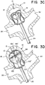
- FIG. 3C illustrates the braid 110 expanding within the outer section 142'.
- FIG. 3D illustrates the braid forming an inner sack 144' inside of the outer section 142'.
- a distal inversion 124' is illustrated positioned near a distal portion 15 of the aneurysm wall 14.
- the distal inversion 124' can correspond to a distal inversion 124 of the braid 110 in the predetermined shape.
- the inner sack 144' can correspond to the middle segment 144 in the predetermined shape illustrated in FIG. 2 .
- the inner sack 144' can correspond to the stiff, distal portion 118 of the braid 110 illustrated in FIG. 1 and/or a portion of the braid 110 having less stiffness than the distal portion 118.
- the inner sack 144' can correspond to a portion of the braid 110 having greater stiffness than the flexible proximal portion 116 illustrated in FIG. 1 .
- FIG. 3E illustrates a collapsible portion 146' of the braid 110 further exiting the catheter 20 and expanding within the inner sack 114'.
- the collapsible portion 146' can correspond to the inner segment 146 of the braid 110 in the predetermined shape.
- the collapsible portion 146' can correspond to the stiff, distal portion 118 of the braid 110 illustrated in FIG. 1 and/or a portion of the braid 110 having less stiffness than the distal portion.
- the collapsible portion 146' can correspond to a portion of the braid 110 having greater stiffness than the flexible proximal portion 116 illustrated in FIG. 1 .
- FIG. 3F illustrates the collapsible portion 146' forming a dome near the distal inversion 124'.
- a pinch point 126' is illustrated on the proximal side of the dome formed by the collapsible portion 146'.
- the pinch point 126' in the implanted shape can correspond to the pinch point 126 in the predetermined shape.
- FIG. 3G illustrates a proximal tail 130' of the braid 110 flattening to a ribbon shape and folding within a space defined by the inner sack 144' and the dome of the collapsible portion 146'.
- the proximal tail 130' can correspond to the proximal tail 130 of the braid in the predetermined shape as illustrated in FIG. 2 .
- the proximal tail 130' can correspond to the flexible, proximal portion 116 illustrated in FIG. 1 .
- FIG. 3H illustrates additional length of the proximal tail 130' folding within the space defined by the inner sack 144' and the dome of the collapsible portion 146'.
- FIG. 3I illustrates the implant 100 in a final implanted shape.
- the outer section 142', inner sack 144', and collapsible portion 146' are illustrated in cross-section to better illustrate the folded ribbon shape of the proximal tail 130'.
- FIG. 4 illustrates an alternative implanted shape of a braid 110.
- the braid 110 can include a twist 125 near the distal inversion 124'. Either with the twist 125 as illustrated in FIG. 4 , or without the twist, as illustrated in FIG. 3I , the inner sack 144' can provide a force F1 pressing into the aneurysm wall 14 and/or the outer section 142', depending on the coverage of the outer section 142'.
- the outer section 142' is also illustrated in an alternative configuration such that the open end 114 is positioned approximate the distal portion 15 of the aneurysm wall 14.
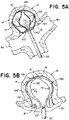
- FIGs. 5A and 5B illustrate subsequent implantation steps of the implant 100 illustrated in FIG. 4 .
- FIG. 5A illustrates a second inner sack 132 expanding within the aforementioned, first inner sack 142'.
- FIG. 5B illustrates the second inner sack 132 providing a second force F2 pressing into the first inner sack 142'.
- the braid 110 is illustrated in cross section in FIG. 5B .
- the braid 110 can form additional nested sacks. Additionally, or alternatively, the braid can collapse to form a ribbon shape and fold into a space defined by one or more nested sacks similar to as illustrated in FIGs. 3G through 3I .
- FIG. 6 illustrates an alternative implant 100a including a braid 110 having two sections 116, 118 of differing braid angle ⁇ 1, ⁇ 4, an embolic coil 160, and a detachment key 150.
- the embolic coil 160 can be attached to a proximal end 112 of the braid 110.
- a proximal portion 116 of the braid 110 near the proximal end 112 can have a small braid angle ⁇ 4.
- a distal portion 118 of the braid 110 near the distal end 114 of the braid can have a larger braid angle ⁇ 4.
- the braid 110 can be shaped into a single layer tubular shape as illustrated in FIG. 6 .
- the braid can be shaped for delivery as described elsewhere herein.
- FIG. 7 illustrates an alternative implant 100a such as the implant 100a illustrated in FIG. 6 having a braid 110 in a predetermined shape.
- the predetermined shape can have four sections 142, 144, 146, 130, two inversions 122, 124, and a pinch point 126 similar to as described in relation to FIG. 2 .
- the embolic coil 160 can extend from the tail section 130 of the braid 100. When implanted, the embolic coil 160 can take the place of some or all of the tail portion 130' of the implant 100 illustrated in FIG. 3I .
- FIG. 8 illustrates an implant 100a such as the implant 100a illustrated in FIG. 6 and/or FIG. 7 in an implanted shape.
- the braid 110 can have an outer section 142' and an inner sack 144' when implanted similar as disclosed in relation to FIG. 3I and/or FIG. 4 .
- the embolic coil 160 can wind within the inner sack 144'.
- FIG. 9 is a flow diagram outlining example method steps for treating an aneurysm with an implant and/or system such as an example implant 100, 100a and/or system described herein, variations thereof, or alternative implant and/or system as would be appreciated and understood by a person ordinary skill in the art.
- an implant and/or system such as an example implant 100, 100a and/or system described herein, variations thereof, or alternative implant and/or system as would be appreciated and understood by a person ordinary skill in the art.
- a tubular braid having a stronger section and a weaker section can be selected.
- the selected tubular braid can include an example tubular braid 110 as described herein, a variation thereof, or an alternative thereto as would be appreciated and understood by a person of ordinary skill in the art.
- the stronger section can have a larger braid angle relative to the weaker section such that the strength of the braid sections is respectively determined at least in part by the respective braid angles.
- one or both of the stronger and weaker sections can be treated (e.g. heat treated) to modify material properties of one or both of the sections such that difference in strength between the two sections is determined at least in part by the treatment.
- the stronger section can have a greater number of strands compared to the weaker section such that the strength of the braid sections is respectively determined at least in part by the number of strands.
- the strands in the stronger section can have a larger diameter compared to the diameter of the strands in the weaker section such that the strength of the braid sections is respectively determined at least in part of the diameter of the strands.
- the strands in the stronger section and the weaker section can include differing materials such that the strength of the sections is respectively determined at least in part by the material properties of the strands.
- the braid can be delivered through a microcatheter to an aneurysm.
- the braid can be detachably attached to an elongated delivery system.
- the implant (and thereby the braid) can be attached to the delivery system at a distal end of the delivery system.
- the delivery system and the implant can be positioned within the microcatheter such that the delivery system extends from a proximal end of the microcatheter.
- a user e.g. physician
- a user can place the implant similar to as illustrated in FIGs. 3A through 3I , FIG. 4 , FIGs.
- FIG. 8 otherwise described herein, or as otherwise understood by a person of ordinary skill in the art according to the teachings herein by manipulating the portion of the delivery system extending from the proximal end of the microcatheter.
- the distal end of the braid can be positioned at a distal portion 15 of the aneurysm wall 14.
- the distal end of the braid can be positioned as illustrated in FIG. 4 , FIGs. 5A through 5B , and/or FIG. 8 .
- the distal end of the braid can be positioned elsewhere, for instance within a middle third of the aneurysm wall 14, about half way between the distal portion 15 of the wall 14 and the aneurysm neck 16 as illustrated in FIGs. 3A through 3I .
- the stronger section of the braid can be expanded to form an outer sack apposing the aneurysm wall 14.
- the outer sack can be shaped similar to the outer sack 142' illustrated in FIG. 4 , FIGs. 5A through 5B , and/or FIG. 8 .
- the stronger section of the braid can be expanded to form a bowl shape similar to the outer section 142' shape illustrated in FIGs. 3A through 3I .
- a proximal inversion can be formed in the braid at the aneurysm's neck.
- the proximal inversion can be positioned similar to the proximal inversion 122' illustrated in FIGs. 3A through 3I , FIG. 4 , FIGs. 5A through 5B , and/or FIG. 8 .
- the proximal inversion can be shaped similar to the proximal inversion 122' illustrated in FIGs. 3A through 3I , FIG. 4 , FIGs. 5A through 5B , and/or FIG. 8 .
- the proximal inversion 122' can define a boundary between the outer sack or outer section expanded in step 308 and an inverted portion positioned within the outer sack or outer section.
- the inverted portion can be expanded to form a sack inside the outer sack or outer section.
- the inverted portion can press against the outer sack (or section), thereby pressing the outer sack (or section) into the aneurysm wall 14.
- the inverted portion can form an inner sack 144' such as illustrated in FIGs. 3A through 3I , FIG. 4 , FIGs. 5A through 5B , and/or FIG. 8 .
- a distal inversion can be formed in the braid.
- the distal inversion can define a distal side of the inverted, inner sack expanded in step 312.
- the distal inversion can define a boundary between the inner sack and an inner, non-inverted portion of the braid.
- the inner, non-inverted portion of the braid can include the weaker section of the braid.
- the weaker section of the braid can be positioned in the inverted sack.
- the weaker section can be flattened to a ribbon shape and folded into the inverted sack.
- the weaker section can be flattened and folded such as illustrated in FIGs. 3G through 3I , as otherwise described herein, and/or as understood by a person of ordinary skill in the art according to the teachings herein.
- the weaker section can correspond to the tail section 130, 130' of the braid 110.
- the descriptions contained herein are examples of embodiments of the invention and are not intended in any way to limit the scope of the invention.
- the invention contemplates many variations and modifications of the implant, including: alternative delivery methods, alternative braid materials, alternative means for achieving a desired stiffness/flexibility of braid material, additional structures affixed to the implant (e.g. to aid in anchoring the implant, blood flow diversion, embolism formation, etc.), alternative predetermined braid shapes (e.g. one inversion, three inversions, four inversions, five or more inversions, non-radially symmetric shapes, alternative segment shapes, etc.), alternative implanted shapes, etc. Modifications apparent to one of ordinary skill in the art following the teachings of this disclosure are intended to be within the scope of the claims which follow.
Landscapes
- Health & Medical Sciences (AREA)
- Surgery (AREA)
- Life Sciences & Earth Sciences (AREA)
- Engineering & Computer Science (AREA)
- Molecular Biology (AREA)
- Animal Behavior & Ethology (AREA)
- Vascular Medicine (AREA)
- Biomedical Technology (AREA)
- Heart & Thoracic Surgery (AREA)
- Medical Informatics (AREA)
- Reproductive Health (AREA)
- Nuclear Medicine, Radiotherapy & Molecular Imaging (AREA)
- General Health & Medical Sciences (AREA)
- Public Health (AREA)
- Veterinary Medicine (AREA)
- Neurosurgery (AREA)
- Manufacturing & Machinery (AREA)
- Textile Engineering (AREA)
- Surgical Instruments (AREA)
- Prostheses (AREA)
Applications Claiming Priority (1)
| Application Number | Priority Date | Filing Date | Title |
|---|---|---|---|
| US16/703,973 US11602350B2 (en) | 2019-12-05 | 2019-12-05 | Intrasaccular inverting braid with highly flexible fill material |
Publications (2)
| Publication Number | Publication Date |
|---|---|
| EP3831316A2 true EP3831316A2 (de) | 2021-06-09 |
| EP3831316A3 EP3831316A3 (de) | 2021-10-13 |
Family
ID=73726734
Family Applications (1)
| Application Number | Title | Priority Date | Filing Date |
|---|---|---|---|
| EP20212016.8A Withdrawn EP3831316A3 (de) | 2019-12-05 | 2020-12-04 | Intrasakkuläres umkehrgeflecht mit hochflexibler füllgutzuweisungserfassung |
Country Status (5)
| Country | Link |
|---|---|
| US (2) | US11602350B2 (de) |
| EP (1) | EP3831316A3 (de) |
| JP (1) | JP7618425B2 (de) |
| KR (1) | KR20210070916A (de) |
| CN (1) | CN112914656A (de) |
Families Citing this family (12)
| Publication number | Priority date | Publication date | Assignee | Title |
|---|---|---|---|---|
| US11357511B2 (en) | 2008-05-01 | 2022-06-14 | Aneuclose Llc | Intrasacular aneurysm occlusion device with globular first configuration and bowl-shaped second configuration |
| US11583289B2 (en) | 2008-05-01 | 2023-02-21 | Aneuclose Llc | Aneurysm-occluding mesh ribbon with a series of loops or segments having distal-to-proximal variation in size, shape, and/or orientation |
| US11471164B2 (en) | 2008-05-01 | 2022-10-18 | Aneuclose Llc | Methods of occluding a cerebral aneurysm by inserting embolic members or material into an intrasacular implant |
| US12004750B2 (en) | 2008-05-01 | 2024-06-11 | Aneuclose Llc | Methods for creating an expandable two-part intrasacular aneurysm occlusion device from a tubular mesh |
| US12102327B2 (en) | 2019-05-25 | 2024-10-01 | Galaxy Therapeutics, Inc. | Systems and methods for treating aneurysms |
| US11166731B2 (en) | 2019-05-25 | 2021-11-09 | Galaxy Therapeutics Inc. | Systems and methods for treating aneurysms |
| US20220167955A1 (en) * | 2020-12-01 | 2022-06-02 | St. Jude Medical, Cardiology Division, Inc. | Medical device for closure of a vascular abnormality |
| EP4284263A4 (de) | 2021-01-27 | 2024-06-26 | Galaxy Therapeutics, Inc. | Systeme und verfahren zur behandlung von aneurysmen |
| KR102442152B1 (ko) | 2021-06-01 | 2022-09-08 | 주식회사 다스 | 시트의 워크인 장치 |
| CN117999037A (zh) * | 2021-09-07 | 2024-05-07 | 史赛克公司 | 血管闭塞设备 |
| CN115530907A (zh) * | 2022-09-29 | 2022-12-30 | 珠海通桥医疗科技有限公司 | 一种颅内动脉瘤介入栓塞治疗装置 |
| DE102023121968A1 (de) | 2023-08-16 | 2025-02-20 | Andratec Gmbh | Okkluder |
Citations (3)
| Publication number | Priority date | Publication date | Assignee | Title |
|---|---|---|---|---|
| US20180242979A1 (en) | 2017-02-23 | 2018-08-30 | DePuy Synthes Products, Inc. | Aneurysm device and delivery system |
| US20190192162A1 (en) | 2017-12-21 | 2019-06-27 | DePuy Synthes Products, Inc. | Implantable medical device detachment system with split tube and cylindrical coupling |
| US20190328398A1 (en) | 2018-04-27 | 2019-10-31 | DePuy Synthes Products, Inc. | Implantable medical device detachment system with split tube |
Family Cites Families (404)
| Publication number | Priority date | Publication date | Assignee | Title |
|---|---|---|---|---|
| US2849002A (en) | 1956-03-12 | 1958-08-26 | Vincent J Oddo | Haemostatic catheter |
| US3480017A (en) | 1966-04-27 | 1969-11-25 | Wallace B Shute | Cervical dilator |
| US4085757A (en) | 1976-04-29 | 1978-04-25 | P Pevsner | Miniature balloon catheter method and apparatus |
| US4282875A (en) | 1979-01-24 | 1981-08-11 | Serbinenko Fedor A | Occlusive device |
| US4395806A (en) | 1980-05-08 | 1983-08-02 | Sorenson Research Co., Inc. | Method of manufacturing a detachable balloon catheter assembly |
| US4364392A (en) | 1980-12-04 | 1982-12-21 | Wisconsin Alumni Research Foundation | Detachable balloon catheter |
| US4545367A (en) | 1982-07-16 | 1985-10-08 | Cordis Corporation | Detachable balloon catheter and method of use |
| US4517979A (en) | 1983-07-14 | 1985-05-21 | Cordis Corporation | Detachable balloon catheter |
| EP0375775B1 (de) | 1986-11-29 | 1994-08-31 | Terumo Kabushiki Kaisha | Mit ballon versehener katheter |
| US4836204A (en) | 1987-07-06 | 1989-06-06 | Landymore Roderick W | Method for effecting closure of a perforation in the septum of the heart |
| US5067489A (en) | 1988-08-16 | 1991-11-26 | Flexmedics Corporation | Flexible guide with safety tip |
| FR2641692A1 (fr) | 1989-01-17 | 1990-07-20 | Nippon Zeon Co | Bouchon de fermeture d'une breche pour application medicale et dispositif pour bouchon de fermeture l'utilisant |
| US4991602A (en) | 1989-06-27 | 1991-02-12 | Flexmedics Corporation | Flexible guide wire with safety tip |
| US5065772A (en) | 1989-10-13 | 1991-11-19 | Inamed Corporation | Inflatable cerivical pessary |
| US6425893B1 (en) | 1990-03-13 | 2002-07-30 | The Regents Of The University Of California | Method and apparatus for fast electrolytic detachment of an implant |
| US5122136A (en) | 1990-03-13 | 1992-06-16 | The Regents Of The University Of California | Endovascular electrolytically detachable guidewire tip for the electroformation of thrombus in arteries, veins, aneurysms, vascular malformations and arteriovenous fistulas |
| JPH0546421Y2 (de) | 1990-08-23 | 1993-12-06 | ||
| US5025060A (en) | 1990-10-15 | 1991-06-18 | Kansai Paint Co., Ltd. | Dispersion of fine particles of a polymer |
| CA2380683C (en) | 1991-10-28 | 2006-08-08 | Advanced Cardiovascular Systems, Inc. | Expandable stents and method for making same |
| DK0791333T3 (da) | 1991-12-12 | 2000-05-01 | Target Therapeutics Inc | Adskillelig udstøder-karokklusionsspiralkonstruktion med sammenlåsende kobling |
| US5261916A (en) | 1991-12-12 | 1993-11-16 | Target Therapeutics | Detachable pusher-vasoocclusive coil assembly with interlocking ball and keyway coupling |
| US5342387A (en) | 1992-06-18 | 1994-08-30 | American Biomed, Inc. | Artificial support for a blood vessel |
| US5350397A (en) | 1992-11-13 | 1994-09-27 | Target Therapeutics, Inc. | Axially detachable embolic coil assembly |
| US5334210A (en) | 1993-04-09 | 1994-08-02 | Cook Incorporated | Vascular occlusion assembly |
| US5624449A (en) | 1993-11-03 | 1997-04-29 | Target Therapeutics | Electrolytically severable joint for endovascular embolic devices |
| US5423829A (en) | 1993-11-03 | 1995-06-13 | Target Therapeutics, Inc. | Electrolytically severable joint for endovascular embolic devices |
| JP2605559Y2 (ja) | 1993-12-21 | 2000-07-24 | 株式会社パイオラックス | 管状器官の治療具 |
| EP1221307B1 (de) | 1994-07-08 | 2010-02-17 | ev3 Inc. | System zum Durchführen eines intravaskulären Verfahrens |
| US5846261A (en) | 1994-07-08 | 1998-12-08 | Aga Medical Corp. | Percutaneous catheter directed occlusion devices |
| US5814062A (en) | 1994-12-22 | 1998-09-29 | Target Therapeutics, Inc. | Implant delivery assembly with expandable coupling/decoupling mechanism |
| IL116561A0 (en) | 1994-12-30 | 1996-03-31 | Target Therapeutics Inc | Severable joint for detachable devices placed within the body |
| US5634936A (en) | 1995-02-06 | 1997-06-03 | Scimed Life Systems, Inc. | Device for closing a septal defect |
| US5645558A (en) | 1995-04-20 | 1997-07-08 | Medical University Of South Carolina | Anatomically shaped vasoocclusive device and method of making the same |
| RU2157146C2 (ru) | 1995-06-13 | 2000-10-10 | ВИЛЬЯМ КУК Европа, A/S | Устройство для имплантации в сосудах и полых органах (его варианты) |
| US6168622B1 (en) | 1996-01-24 | 2001-01-02 | Microvena Corporation | Method and apparatus for occluding aneurysms |
| US5733294A (en) | 1996-02-28 | 1998-03-31 | B. Braun Medical, Inc. | Self expanding cardiovascular occlusion device, method of using and method of making the same |
| US5853422A (en) | 1996-03-22 | 1998-12-29 | Scimed Life Systems, Inc. | Apparatus and method for closing a septal defect |
| US6949116B2 (en) | 1996-05-08 | 2005-09-27 | Carag Ag | Device for plugging an opening such as in a wall of a hollow or tubular organ including biodegradable elements |
| US5964797A (en) * | 1996-08-30 | 1999-10-12 | Target Therapeutics, Inc. | Electrolytically deployable braided vaso-occlusion device |
| US5941249A (en) | 1996-09-05 | 1999-08-24 | Maynard; Ronald S. | Distributed activator for a two-dimensional shape memory alloy |
| US6007573A (en) | 1996-09-18 | 1999-12-28 | Microtherapeutics, Inc. | Intracranial stent and method of use |
| US6254628B1 (en) | 1996-12-09 | 2001-07-03 | Micro Therapeutics, Inc. | Intracranial stent |
| US5951599A (en) | 1997-07-09 | 1999-09-14 | Scimed Life Systems, Inc. | Occlusion system for endovascular treatment of an aneurysm |
| US5928260A (en) | 1997-07-10 | 1999-07-27 | Scimed Life Systems, Inc. | Removable occlusion system for aneurysm neck |
| JP4060528B2 (ja) | 1997-08-04 | 2008-03-12 | ボストン サイエンティフィック コーポレーション | 動脈瘤治療のための閉塞システム |
| GB9716497D0 (en) | 1997-08-05 | 1997-10-08 | Bridport Gundry Plc | Occlusion device |
| WO1999008607A1 (en) | 1997-08-05 | 1999-02-25 | Boston Scientific Limited | Detachable aneurysm neck bridge |
| US6063070A (en) | 1997-08-05 | 2000-05-16 | Target Therapeutics, Inc. | Detachable aneurysm neck bridge (II) |
| US6086577A (en) | 1997-08-13 | 2000-07-11 | Scimed Life Systems, Inc. | Detachable aneurysm neck bridge (III) |
| US5916235A (en) | 1997-08-13 | 1999-06-29 | The Regents Of The University Of California | Apparatus and method for the use of detachable coils in vascular aneurysms and body cavities |
| US6146373A (en) | 1997-10-17 | 2000-11-14 | Micro Therapeutics, Inc. | Catheter system and method for injection of a liquid embolic composition and a solidification agent |
| US6036720A (en) | 1997-12-15 | 2000-03-14 | Target Therapeutics, Inc. | Sheet metal aneurysm neck bridge |
| JP2003522550A (ja) | 1998-02-10 | 2003-07-29 | アーテミス・メディカル・インコーポレイテッド | 咬合、固定、テンショニング、及び流向装置とその使用方法 |
| US6063100A (en) | 1998-03-10 | 2000-05-16 | Cordis Corporation | Embolic coil deployment system with improved embolic coil |
| US6379374B1 (en) | 1998-10-22 | 2002-04-30 | Cordis Neurovascular, Inc. | Small diameter embolic coil hydraulic deployment system |
| US5925060A (en) | 1998-03-13 | 1999-07-20 | B. Braun Celsa | Covered self-expanding vascular occlusion device |
| CA2326504A1 (en) | 1998-03-30 | 1999-10-07 | David Forest Kallmes | Flow arrest, double balloon technique for occluding aneurysms or blood vessels |
| US6168615B1 (en) | 1998-05-04 | 2001-01-02 | Micrus Corporation | Method and apparatus for occlusion and reinforcement of aneurysms |
| SE514546C2 (sv) | 1998-05-18 | 2001-03-12 | Allgon Ab | Ett antennsystem och en radiokommunikationsanordning innefattande ett antennsystem |
| US6463317B1 (en) | 1998-05-19 | 2002-10-08 | Regents Of The University Of Minnesota | Device and method for the endovascular treatment of aneurysms |
| US6113609A (en) | 1998-05-26 | 2000-09-05 | Scimed Life Systems, Inc. | Implantable tissue fastener and system for treating gastroesophageal reflux disease |
| US5935148A (en) | 1998-06-24 | 1999-08-10 | Target Therapeutics, Inc. | Detachable, varying flexibility, aneurysm neck bridge |
| US6096175A (en) | 1998-07-17 | 2000-08-01 | Micro Therapeutics, Inc. | Thin film stent |
| US7410482B2 (en) | 1998-09-04 | 2008-08-12 | Boston Scientific-Scimed, Inc. | Detachable aneurysm neck bridge |
| EP1109499B1 (de) | 1998-09-04 | 2007-08-15 | Boston Scientific Limited | Ablösbares system zum verschliessen eines aneurysmashalses |
| AU6288799A (en) | 1998-10-09 | 2000-05-01 | Cook Incorporated | Vasoocclusion coil device having a core therein |
| US7128073B1 (en) | 1998-11-06 | 2006-10-31 | Ev3 Endovascular, Inc. | Method and device for left atrial appendage occlusion |
| US7044134B2 (en) | 1999-11-08 | 2006-05-16 | Ev3 Sunnyvale, Inc | Method of implanting a device in the left atrial appendage |
| US6569179B2 (en) | 1998-11-10 | 2003-05-27 | Scimed Life Systems, Inc. | Bioactive three loop coil |
| US8016852B2 (en) | 1998-11-10 | 2011-09-13 | Stryker Corporation | Bioactive components for incorporation with vaso-occlusive members |
| US6080183A (en) | 1998-11-24 | 2000-06-27 | Embol-X, Inc. | Sutureless vessel plug and methods of use |
| EP1582178B1 (de) | 1999-02-01 | 2012-09-26 | Board Of Regents, The University Of Texas System | Gewebte intravaskuläre Vorrichtung und Verfahren zur Herstellung |
| US6428558B1 (en) | 1999-03-10 | 2002-08-06 | Cordis Corporation | Aneurysm embolization device |
| US6375606B1 (en) | 1999-03-17 | 2002-04-23 | Stereotaxis, Inc. | Methods of and apparatus for treating vascular defects |
| US6858034B1 (en) | 1999-05-20 | 2005-02-22 | Scimed Life Systems, Inc. | Stent delivery system for prevention of kinking, and method of loading and using same |
| US6379329B1 (en) | 1999-06-02 | 2002-04-30 | Cordis Neurovascular, Inc. | Detachable balloon embolization device and method |
| US6375668B1 (en) | 1999-06-02 | 2002-04-23 | Hanson S. Gifford | Devices and methods for treating vascular malformations |
| US6551303B1 (en) | 1999-10-27 | 2003-04-22 | Atritech, Inc. | Barrier device for ostium of left atrial appendage |
| US6689150B1 (en) | 1999-10-27 | 2004-02-10 | Atritech, Inc. | Filter apparatus for ostium of left atrial appendage |
| US6994092B2 (en) | 1999-11-08 | 2006-02-07 | Ev3 Sunnyvale, Inc. | Device for containing embolic material in the LAA having a plurality of tissue retention structures |
| US6331184B1 (en) | 1999-12-10 | 2001-12-18 | Scimed Life Systems, Inc. | Detachable covering for an implantable medical device |
| US6350270B1 (en) | 2000-01-24 | 2002-02-26 | Scimed Life Systems, Inc. | Aneurysm liner |
| US6391037B1 (en) | 2000-03-02 | 2002-05-21 | Prodesco, Inc. | Bag for use in the intravascular treatment of saccular aneurysms |
| US6346117B1 (en) | 2000-03-02 | 2002-02-12 | Prodesco, Inc. | Bag for use in the intravascular treatment of saccular aneurysms |
| US7153323B1 (en) | 2000-06-30 | 2006-12-26 | Boston Scientific Scimed, Inc. | Aneurysm liner with multi-segment extender |
| US20020068974A1 (en) | 2000-07-21 | 2002-06-06 | Kuslich Stephen D. | Expandable porous mesh bag device and methods of use for reduction, filling, fixation and supporting of bone |
| US6855154B2 (en) | 2000-08-11 | 2005-02-15 | University Of Louisville Research Foundation, Inc. | Endovascular aneurysm treatment device and method |
| EP1399213A4 (de) | 2000-10-11 | 2008-03-19 | Micro Therapeutics Inc | Verfahren zur behandlung von aneurismen |
| WO2002069783A2 (en) | 2000-10-24 | 2002-09-12 | Concentric Medical, Inc. | Device and methods for treating vascular malformations |
| US6547804B2 (en) | 2000-12-27 | 2003-04-15 | Scimed Life Systems, Inc. | Selectively permeable highly distensible occlusion balloon |
| US6866677B2 (en) | 2001-04-03 | 2005-03-15 | Medtronic Ave, Inc. | Temporary intraluminal filter guidewire and methods of use |
| US20020147497A1 (en) | 2001-04-06 | 2002-10-10 | Integrated Vascular Systems, Inc. | Methods for treating spinal discs |
| US20020188314A1 (en) | 2001-06-07 | 2002-12-12 | Microvena Corporation | Radiopaque distal embolic protection device |
| US6454780B1 (en) | 2001-06-21 | 2002-09-24 | Scimed Life Systems, Inc. | Aneurysm neck obstruction device |
| US20030181927A1 (en) | 2001-06-21 | 2003-09-25 | Wallace Michael P. | Aneurysm neck obstruction device |
| US6572628B2 (en) | 2001-06-28 | 2003-06-03 | Cordis Neurovascular, Inc. | Method and apparatus for placing a medical agent into a vessel of the body |
| US6964671B2 (en) | 2001-06-28 | 2005-11-15 | Cordis Neurovascular, Inc. | Method and apparatus for placing a medical agent into a vessel of the body |
| US8252040B2 (en) | 2001-07-20 | 2012-08-28 | Microvention, Inc. | Aneurysm treatment device and method of use |
| US8715312B2 (en) | 2001-07-20 | 2014-05-06 | Microvention, Inc. | Aneurysm treatment device and method of use |
| US7572288B2 (en) | 2001-07-20 | 2009-08-11 | Microvention, Inc. | Aneurysm treatment device and method of use |
| US20030028209A1 (en) | 2001-07-31 | 2003-02-06 | Clifford Teoh | Expandable body cavity liner device |
| US6811560B2 (en) | 2001-09-20 | 2004-11-02 | Cordis Neurovascular, Inc. | Stent aneurysm embolization method and device |
| US6802851B2 (en) | 2001-09-20 | 2004-10-12 | Gordia Neurovascular, Inc. | Stent aneurysm embolization method using collapsible member and embolic coils |
| AU2002352628B2 (en) | 2001-11-09 | 2006-06-29 | Rubicon Medical, Inc. | Stent delivery device with embolic protection |
| JP4429589B2 (ja) | 2001-11-15 | 2010-03-10 | コーディス・ニューロバスキュラー・インコーポレイテッド | 閉塞部材を用いる動脈瘤塞栓装置 |
| JP2003190175A (ja) | 2001-11-15 | 2003-07-08 | Cordis Neurovascular Inc | 動脈瘤を密閉するための動脈瘤頚部プラグ |
| US20060292206A1 (en) | 2001-11-26 | 2006-12-28 | Kim Steven W | Devices and methods for treatment of vascular aneurysms |
| DE60317474T2 (de) | 2002-03-05 | 2008-10-02 | Salviac Ltd. | System aus embolischem filter und rückziehschlinge |
| US6773448B2 (en) | 2002-03-08 | 2004-08-10 | Ev3 Inc. | Distal protection devices having controllable wire motion |
| US20030176884A1 (en) | 2002-03-12 | 2003-09-18 | Marwane Berrada | Everted filter device |
| JP4465192B2 (ja) | 2002-03-15 | 2010-05-19 | エヌエムティー メディカル, インコーポレイティッド | 移植物の配置において有用な結合システム |
| US7695488B2 (en) | 2002-03-27 | 2010-04-13 | Boston Scientific Scimed, Inc. | Expandable body cavity liner device |
| US20030195553A1 (en) | 2002-04-12 | 2003-10-16 | Scimed Life Systems, Inc. | System and method for retaining vaso-occlusive devices within an aneurysm |
| US6833003B2 (en) | 2002-06-24 | 2004-12-21 | Cordis Neurovascular | Expandable stent and delivery system |
| US20040034386A1 (en) | 2002-08-19 | 2004-02-19 | Michael Fulton | Aneurysm stent |
| US20040044391A1 (en) | 2002-08-29 | 2004-03-04 | Stephen Porter | Device for closure of a vascular defect and method of treating the same |
| US8075585B2 (en) | 2002-08-29 | 2011-12-13 | Stryker Corporation | Device and method for treatment of a vascular defect |
| US7229454B2 (en) | 2003-01-07 | 2007-06-12 | Boston Scientific Scimed, Inc. | Occlusive cinching devices and methods of use |
| US20040254594A1 (en) | 2003-01-24 | 2004-12-16 | Arthur Alfaro | Cardiac defect occlusion device |
| US7744583B2 (en) | 2003-02-03 | 2010-06-29 | Boston Scientific Scimed | Systems and methods of de-endothelialization |
| US7293562B2 (en) | 2003-03-27 | 2007-11-13 | Cierra, Inc. | Energy based devices and methods for treatment of anatomic tissue defects |
| US7001369B2 (en) | 2003-03-27 | 2006-02-21 | Scimed Life Systems, Inc. | Medical device |
| TWI221091B (en) | 2003-04-18 | 2004-09-21 | A Spine Holding Group Corp | Spine filling device |
| US7597704B2 (en) | 2003-04-28 | 2009-10-06 | Atritech, Inc. | Left atrial appendage occlusion device with active expansion |
| US7803395B2 (en) | 2003-05-15 | 2010-09-28 | Biomerix Corporation | Reticulated elastomeric matrices, their manufacture and use in implantable devices |
| US7093527B2 (en) | 2003-06-10 | 2006-08-22 | Surpass Medical Ltd. | Method and apparatus for making intraluminal implants and construction particularly useful in such method and apparatus |
| US7309345B2 (en) | 2003-07-25 | 2007-12-18 | Boston Scientific-Scimed, Inc. | Method and system for delivering an implant utilizing a lumen reducing member |
| US7735493B2 (en) | 2003-08-15 | 2010-06-15 | Atritech, Inc. | System and method for delivering a left atrial appendage containment device |
| DE10338702B9 (de) | 2003-08-22 | 2007-04-26 | Occlutech Gmbh | Occlusioninstrument |
| US7371228B2 (en) | 2003-09-19 | 2008-05-13 | Medtronic Vascular, Inc. | Delivery of therapeutics to treat aneurysms |
| US7232461B2 (en) | 2003-10-29 | 2007-06-19 | Cordis Neurovascular, Inc. | Neck covering device for an aneurysm |
| WO2005044142A2 (en) | 2003-11-10 | 2005-05-19 | Angiotech International Ag | Intravascular devices and fibrosis-inducing agents |
| US8231649B2 (en) | 2004-01-20 | 2012-07-31 | Boston Scientific Scimed, Inc. | Retrievable blood clot filter with retractable anchoring members |
| WO2005074517A2 (en) | 2004-01-30 | 2005-08-18 | Nmt Medical, Inc. | Welding systems for closure of cardiac openings |
| US7678129B1 (en) | 2004-03-19 | 2010-03-16 | Advanced Cardiovascular Systems, Inc. | Locking component for an embolic filter assembly |
| US9039724B2 (en) | 2004-03-19 | 2015-05-26 | Aga Medical Corporation | Device for occluding vascular defects |
| US8777974B2 (en) | 2004-03-19 | 2014-07-15 | Aga Medical Corporation | Multi-layer braided structures for occluding vascular defects |
| US20050228434A1 (en) | 2004-03-19 | 2005-10-13 | Aga Medical Corporation | Multi-layer braided structures for occluding vascular defects |
| BE1016067A3 (fr) | 2004-06-03 | 2006-02-07 | Frid Noureddine | Endoprothese luminale pour occlusion d'anevrisme et procede de fabrication d'une telle endoprothese. |
| US9308382B2 (en) | 2004-06-10 | 2016-04-12 | Medtronic Urinary Solutions, Inc. | Implantable pulse generator systems and methods for providing functional and/or therapeutic stimulation of muscles and/or nerves and/or central nervous system tissue |
| US8048145B2 (en) | 2004-07-22 | 2011-11-01 | Endologix, Inc. | Graft systems having filling structures supported by scaffolds and methods for their use |
| US20060052816A1 (en) | 2004-08-31 | 2006-03-09 | Cook Incorporated | Device for treating an aneurysm |
| US9655633B2 (en) | 2004-09-10 | 2017-05-23 | Penumbra, Inc. | System and method for treating ischemic stroke |
| US7244270B2 (en) | 2004-09-16 | 2007-07-17 | Evera Medical | Systems and devices for soft tissue augmentation |
| JP2008513141A (ja) | 2004-09-17 | 2008-05-01 | コーディス・ニューロバスキュラー・インコーポレイテッド | 動脈瘤または血管を施栓する薄膜金属器具 |
| WO2006034153A2 (en) | 2004-09-17 | 2006-03-30 | Cordis Neurovascular, Inc. | Thin film metallic devices for plugging aneurysms or vessels |
| US8444668B2 (en) | 2004-09-17 | 2013-05-21 | DePuy Synthes Products, LLC | Expandable vascular occlusion device |
| CA2581272A1 (en) | 2004-09-22 | 2006-05-18 | Lee R. Guterman | Cranial aneurysm treatment arrangement |
| US20060089637A1 (en) | 2004-10-14 | 2006-04-27 | Werneth Randell L | Ablation catheter |
| JP2008519613A (ja) | 2004-11-09 | 2008-06-12 | ボストン サイエンティフィック リミテッド | 複合形状近位部分およびより小さな直径遠位を備える血管閉塞デバイス |
| US20060106421A1 (en) | 2004-11-16 | 2006-05-18 | Clifford Teoh | Expansible neck bridge |
| US8562672B2 (en) | 2004-11-19 | 2013-10-22 | Medtronic, Inc. | Apparatus for treatment of cardiac valves and method of its manufacture |
| US9545300B2 (en) | 2004-12-22 | 2017-01-17 | W. L. Gore & Associates, Inc. | Filament-wound implantable devices |
| US20060155367A1 (en) | 2005-01-07 | 2006-07-13 | Hines Richard A | Micro-pleated stent assembly |
| US20060155323A1 (en) | 2005-01-07 | 2006-07-13 | Porter Stephen C | Intra-aneurysm devices |
| WO2006078988A2 (en) | 2005-01-21 | 2006-07-27 | Loubert Suddaby | Aneurysm repair method and apparatus |
| US8025668B2 (en) | 2005-04-28 | 2011-09-27 | C. R. Bard, Inc. | Medical device removal system |
| US7377932B2 (en) | 2005-06-02 | 2008-05-27 | Cordis Neurovascular, Inc. | Embolic coil delivery system with mechanical release mechanism |
| US7985238B2 (en) | 2005-06-02 | 2011-07-26 | Codman & Shurtleff, Inc. | Embolic coil delivery system with spring wire release mechanism |
| US9636115B2 (en) | 2005-06-14 | 2017-05-02 | Stryker Corporation | Vaso-occlusive delivery device with kink resistant, flexible distal end |
| CN101309651B (zh) | 2005-06-20 | 2011-12-07 | 麦德托尼克消融前沿有限公司 | 消融导管 |
| US8545530B2 (en) | 2005-10-19 | 2013-10-01 | Pulsar Vascular, Inc. | Implantable aneurysm closure systems and methods |
| KR101334502B1 (ko) | 2005-10-19 | 2013-12-05 | 펄사 배스큘러, 아이엔씨. | 내강과 조직 결함을 치료하고 혈관내 결찰을 위한 장치 및 시스템 |
| CA2630021C (en) | 2005-11-17 | 2013-08-13 | Microvention, Inc. | Three-dimensional complex coil |
| WO2007076480A2 (en) | 2005-12-23 | 2007-07-05 | Levy Elad I | Bifurcated aneurysm treatment arrangement |
| US20070167876A1 (en) | 2006-01-17 | 2007-07-19 | Euteneuer Charles L | Occluding guidewire and methods |
| US20070186933A1 (en) | 2006-01-17 | 2007-08-16 | Pulmonx | Systems and methods for delivering flow restrictive element to airway in lungs |
| US7744652B2 (en) | 2006-01-23 | 2010-06-29 | Hesham Morsi | Aneurysm sealing device |
| CN101049266B (zh) | 2006-04-03 | 2010-11-17 | 孟坚 | 医疗用闭塞器械及其制造方法 |
| US8221447B2 (en) | 2006-03-14 | 2012-07-17 | Thermopeutix, Inc. | Aneurysm coil delivery system |
| CN101431963A (zh) | 2006-03-24 | 2009-05-13 | 比奥米瑞斯公司 | 用于动脉瘤闭塞的自膨胀血管内装置 |
| US9757260B2 (en) | 2006-03-30 | 2017-09-12 | Medtronic Vascular, Inc. | Prosthesis with guide lumen |
| US7763036B2 (en) | 2006-03-31 | 2010-07-27 | Ethicon Endo-Surgery, Inc. | Endoscopic instrument with secondary vacuum source |
| US9615832B2 (en) | 2006-04-07 | 2017-04-11 | Penumbra, Inc. | Aneurysm occlusion system and method |
| US20070288083A1 (en) | 2006-05-12 | 2007-12-13 | Hines Richard A | Exclusion Device and System For Delivery |
| JP2010500917A (ja) | 2006-06-15 | 2010-01-14 | マイクロベンション, インコーポレイテッド | 膨張性ポリマーで構成される塞栓形成デバイス |
| US8062325B2 (en) | 2006-07-31 | 2011-11-22 | Codman & Shurtleff, Inc. | Implantable medical device detachment system and methods of using the same |
| US20080097401A1 (en) | 2006-09-22 | 2008-04-24 | Trapp Benjamin M | Cerebral vasculature device |
| DE102006050385A1 (de) | 2006-10-05 | 2008-04-10 | pfm Produkte für die Medizin AG | Implantierbare Einrichtung |
| US20080103505A1 (en) | 2006-10-26 | 2008-05-01 | Hendrik Raoul Andre Fransen | Containment device for site-specific delivery of a therapeutic material and methods of use |
| WO2008063455A1 (en) | 2006-11-13 | 2008-05-29 | Hines Richard A | Over-the wire exclusion device and system for delivery |
| ATE485013T1 (de) | 2006-11-20 | 2010-11-15 | Septrx Inc | Vorrichtung zur verhinderung des nicht erwünschten durchflusses der embolis von den venen in die arterien |
| US20080281350A1 (en) | 2006-12-13 | 2008-11-13 | Biomerix Corporation | Aneurysm Occlusion Devices |
| US11166703B2 (en) | 2007-01-23 | 2021-11-09 | Cvdevices, Llc | Devices, systems, and methods for atrial appendage occlusion using light cure |
| EP2460476B1 (de) | 2007-04-16 | 2020-11-25 | Occlutech Holding AG | Occluder zum Verschließen eines Herzohres und Herstellungsverfahren dafür |
| AU2008254770A1 (en) | 2007-05-18 | 2008-11-27 | Stryker Corporation | Medical implant detachment systems |
| AU2008260629A1 (en) | 2007-05-31 | 2008-12-11 | Rex Medical, L.P. | Closure device for left atrial appendage |
| WO2008151204A1 (en) | 2007-06-04 | 2008-12-11 | Sequent Medical Inc. | Methods and devices for treatment of vascular defects |
| US8034061B2 (en) | 2007-07-12 | 2011-10-11 | Aga Medical Corporation | Percutaneous catheter directed intravascular occlusion devices |
| US8361138B2 (en) | 2007-07-25 | 2013-01-29 | Aga Medical Corporation | Braided occlusion device having repeating expanded volume segments separated by articulation segments |
| US8500773B2 (en) | 2007-08-01 | 2013-08-06 | Boston Scientific Scimed, Inc. | Spring detach joint for delivering a detachable implantable device |
| US9084589B2 (en) | 2007-08-02 | 2015-07-21 | Occlutech Holding Ag | Method of producing a medical implantable device and medical implantable device |
| US20090082803A1 (en) | 2007-09-26 | 2009-03-26 | Aga Medical Corporation | Braided vascular devices having no end clamps |
| US9414842B2 (en) | 2007-10-12 | 2016-08-16 | St. Jude Medical, Cardiology Division, Inc. | Multi-component vascular device |
| US8066757B2 (en) | 2007-10-17 | 2011-11-29 | Mindframe, Inc. | Blood flow restoration and thrombus management methods |
| AU2008345590B2 (en) | 2007-12-21 | 2014-10-30 | Microvention, Inc. | Hydrogel filaments for biomedical uses |
| US9259225B2 (en) | 2008-02-19 | 2016-02-16 | St. Jude Medical, Cardiology Division, Inc. | Medical devices for treating a target site and associated method |
| US9138213B2 (en) | 2008-03-07 | 2015-09-22 | W.L. Gore & Associates, Inc. | Heart occlusion devices |
| JP4719757B2 (ja) | 2008-03-19 | 2011-07-06 | シスメックス株式会社 | 生体成分分析装置、生体成分分析装置の反応カートリッジおよび生体成分分析装置の抽出カートリッジ |
| US8974518B2 (en) | 2008-03-25 | 2015-03-10 | Medtronic Vascular, Inc. | Eversible branch stent-graft and deployment method |
| DE102008015781B4 (de) | 2008-03-26 | 2011-09-29 | Malte Neuss | Vorrichtung zum Verschluss von Defekten im Gefäßsystem |
| JP5610542B2 (ja) | 2008-04-21 | 2014-10-22 | コヴィディエン リミテッド パートナーシップ | ブレードボール塞栓装置および送達システム |
| EP2192947A1 (de) | 2008-04-30 | 2010-06-09 | Medtronic, Inc. | Verfahren zur platzierung medizinischer ableitungen zur elektrischen stimulation von nervengewebe |
| WO2009134337A1 (en) | 2008-05-01 | 2009-11-05 | Aneuclose Llc | Aneurysm occlusion device |
| US10716573B2 (en) * | 2008-05-01 | 2020-07-21 | Aneuclose | Janjua aneurysm net with a resilient neck-bridging portion for occluding a cerebral aneurysm |
| US11464518B2 (en) | 2008-05-01 | 2022-10-11 | Aneuclose Llc | Proximal concave neck bridge with central lumen and distal net for occluding cerebral aneurysms |
| WO2009135166A2 (en) | 2008-05-02 | 2009-11-05 | Sequent Medical Inc. | Filamentary devices for treatment of vascular defects |
| US8454632B2 (en) | 2008-05-12 | 2013-06-04 | Xlumena, Inc. | Tissue anchor for securing tissue layers |
| US8070694B2 (en) | 2008-07-14 | 2011-12-06 | Medtronic Vascular, Inc. | Fiber based medical devices and aspiration catheters |
| US8333796B2 (en) | 2008-07-15 | 2012-12-18 | Penumbra, Inc. | Embolic coil implant system and implantation method |
| US9351715B2 (en) | 2008-07-24 | 2016-05-31 | St. Jude Medical, Cardiology Division, Inc. | Multi-layered medical device for treating a target site and associated method |
| US9232992B2 (en) | 2008-07-24 | 2016-01-12 | Aga Medical Corporation | Multi-layered medical device for treating a target site and associated method |
| US8262692B2 (en) | 2008-09-05 | 2012-09-11 | Merlin Md Pte Ltd | Endovascular device |
| US20100069948A1 (en) | 2008-09-12 | 2010-03-18 | Micrus Endovascular Corporation | Self-expandable aneurysm filling device, system and method of placement |
| US8721714B2 (en) | 2008-09-17 | 2014-05-13 | Medtronic Corevalve Llc | Delivery system for deployment of medical devices |
| US8992568B2 (en) | 2008-10-20 | 2015-03-31 | Neil Duggal | Systems and methods for cerebrospinal fluid repair |
| US8523902B2 (en) | 2009-01-30 | 2013-09-03 | Kfx Medical Corporation | System and method for attaching soft tissue to bone |
| US9717500B2 (en) | 2009-04-15 | 2017-08-01 | Microvention, Inc. | Implant delivery system |
| US8398671B2 (en) | 2009-04-16 | 2013-03-19 | Stryker Corporation | Electrical contact for occlusive device delivery system |
| WO2010134914A1 (en) | 2009-05-20 | 2010-11-25 | University Of Miami | Spherical helix embolic coils for the treatment of cerebral aneurysms |
| US8758423B2 (en) | 2009-06-18 | 2014-06-24 | Graftcraft I Goteborg Ab | Device and method for treating ruptured aneurysms |
| US20120010644A1 (en) | 2009-07-09 | 2012-01-12 | Sideris Eleftherios B | Method and apparatus for occluding a physiological opening |
| EP2453940A2 (de) | 2009-07-13 | 2012-05-23 | Yissum Research Development Company of The Hebrew University of Jerusalem | Intraluminale polymervorrichtungen zur behandlung von aneurysmen |
| WO2011038017A1 (en) | 2009-09-22 | 2011-03-31 | Penumbra, Inc. | Manual actuation system for deployment of implant |
| CA2778639A1 (en) | 2009-11-05 | 2011-05-12 | Sequent Medical Inc. | Multiple layer filamentary devices or treatment of vascular defects |
| US9095342B2 (en) | 2009-11-09 | 2015-08-04 | Covidien Lp | Braid ball embolic device features |
| US9814562B2 (en) | 2009-11-09 | 2017-11-14 | Covidien Lp | Interference-relief type delivery detachment systems |
| US8226657B2 (en) | 2009-11-10 | 2012-07-24 | Carefusion 207, Inc. | Systems and methods for vertebral or other bone structure height restoration and stabilization |
| US8734458B2 (en) | 2009-12-07 | 2014-05-27 | Globus Medical, Inc. | Methods and apparatus for treating vertebral fractures |
| DE102009058132B4 (de) | 2009-12-12 | 2014-07-24 | Bentley Surgical Gmbh | Zylindrischer Okkluder zur Abdichtung hohlzylindrischer Körpergefäße |
| CN102188300B (zh) | 2010-03-02 | 2014-05-28 | 上海微创医疗器械(集团)有限公司 | 一种动脉瘤手术装置 |
| KR20130054952A (ko) | 2010-04-14 | 2013-05-27 | 마이크로벤션, 인코포레이티드 | 임플란트 전달 장치 |
| US8764811B2 (en) | 2010-04-20 | 2014-07-01 | Medtronic Vascular, Inc. | Controlled tip release stent graft delivery system and method |
| ES2403009T3 (es) | 2010-05-23 | 2013-05-13 | Occlutech Holding Ag | Dispositivo médico trenzado y método para su fabricación |
| WO2011163596A1 (en) | 2010-06-25 | 2011-12-29 | Fort Wayne Metals Research Products Corporation | Biodegradable composite wire for medical devices |
| US8876878B2 (en) | 2010-07-23 | 2014-11-04 | Medtronic, Inc. | Attachment mechanism for stent release |
| AU2011298843A1 (en) | 2010-09-06 | 2013-04-04 | Nonwotecc Medical Gmbh | Device for closing openings or cavities in blood vessels |
| US20130066357A1 (en) | 2010-09-10 | 2013-03-14 | Maria Aboytes | Devices and methods for the treatment of vascular defects |
| US8998947B2 (en) | 2010-09-10 | 2015-04-07 | Medina Medical, Inc. | Devices and methods for the treatment of vascular defects |
| US8974512B2 (en) | 2010-09-10 | 2015-03-10 | Medina Medical, Inc. | Devices and methods for the treatment of vascular defects |
| CN101933850B (zh) | 2010-09-16 | 2012-07-18 | 先健科技(深圳)有限公司 | 封堵器及其制造方法 |
| US8616040B2 (en) | 2010-09-17 | 2013-12-31 | Medtronic Vascular, Inc. | Method of forming a drug-eluting medical device |
| DE102010053111B4 (de) | 2010-12-01 | 2012-10-25 | Acandis Gmbh & Co. Kg | Anordnung mit einer Vorrichtung zur Zufuhr eines medizinischen Funktionselements |
| KR20140004679A (ko) | 2010-12-20 | 2014-01-13 | 마이크로벤션, 인코포레이티드 | 폴리머 스텐트 및 제조방법 |
| US20120165732A1 (en) | 2010-12-23 | 2012-06-28 | Synthes Usa, Llc | Balloon catheter comprising a zero-profile tip |
| US11484318B2 (en) | 2011-01-17 | 2022-11-01 | Artio Medical, Inc. | Expandable body device and method of use |
| AU2012207387B2 (en) | 2011-01-17 | 2017-02-16 | Artio Medical, Inc. | Ballstent device and methods of use |
| US8647358B2 (en) | 2011-01-21 | 2014-02-11 | Obalon Therapeutics Inc. | Intragastric device |
| DE102011011869A1 (de) | 2011-02-22 | 2012-08-23 | Phenox Gmbh | Implantat |
| CA2828960A1 (en) | 2011-03-02 | 2012-09-07 | Joe Michael Eskridge | Endovascular closure system |
| US20120283768A1 (en) | 2011-05-05 | 2012-11-08 | Sequent Medical Inc. | Method and apparatus for the treatment of large and giant vascular defects |
| US9486604B2 (en) | 2011-05-12 | 2016-11-08 | Medtronic, Inc. | Packaging and preparation tray for a delivery system |
| WO2012158668A1 (en) | 2011-05-17 | 2012-11-22 | Stryker Corporation | Method of fabricating an implantable medical device that includes one or more thin film polymer support layers |
| CN103841905B (zh) | 2011-05-23 | 2017-04-12 | 柯惠有限合伙公司 | 取出系统及其使用方法 |
| WO2012166467A1 (en) | 2011-05-27 | 2012-12-06 | Stryker Corporation | Assembly for percutaneously inserting an implantable medical device, steering the device to a target location and deploying the device |
| DE102011102955B4 (de) | 2011-05-31 | 2018-05-03 | Acandis Gmbh & Co. Kg | Medizinisches Implantat zur Anordnung eines Hohlkörpers, insbesondere eines Aneurysmas, und Verfahren zum Herstellen eines medizinischen Implantats |
| KR102019025B1 (ko) | 2011-06-03 | 2019-09-06 | 펄사 배스큘라, 아이엔씨. | 해부학적 구멍을 둘러싸기 위한 시스템 및 방법, 가령, 충격 흡수 동맥류 장치 |
| US8764787B2 (en) | 2011-06-17 | 2014-07-01 | Aga Medical Corporation | Occlusion device and associated deployment method |
| US20120330341A1 (en) | 2011-06-22 | 2012-12-27 | Becking Frank P | Folded-Flat Aneurysm Embolization Devices |
| US9161837B2 (en) | 2011-07-27 | 2015-10-20 | The Cleveland Clinic Foundation | Apparatus, system, and method for treating a regurgitant heart valve |
| US9198668B2 (en) | 2011-08-04 | 2015-12-01 | Cook Medical Technologies Llc | Cerebral aneurysm closure device |
| US20130035665A1 (en) | 2011-08-05 | 2013-02-07 | W. L. Gore & Associates, Inc. | Polymer-Based Occlusion Devices, Systems and Methods |
| EP2567663A1 (de) | 2011-09-09 | 2013-03-13 | Occlutech Holding AG | Faltbare medizinische Verschlussvorrichtung, Verfahren und medizinisches System zur Abgabe eines Objekts |
| US8734500B2 (en) | 2011-09-27 | 2014-05-27 | DePuy Synthes Products, LLC | Distal detachment mechanisms for vascular devices |
| US9750565B2 (en) | 2011-09-30 | 2017-09-05 | Medtronic Advanced Energy Llc | Electrosurgical balloons |
| US8261648B1 (en) | 2011-10-17 | 2012-09-11 | Sequent Medical Inc. | Braiding mechanism and methods of use |
| US8993831B2 (en) | 2011-11-01 | 2015-03-31 | Arsenal Medical, Inc. | Foam and delivery system for treatment of postpartum hemorrhage |
| US9579104B2 (en) | 2011-11-30 | 2017-02-28 | Covidien Lp | Positioning and detaching implants |
| IN2014DN05897A (de) * | 2012-01-06 | 2015-06-05 | Inceptus Medical LLC | |
| JP6356612B2 (ja) | 2012-01-17 | 2018-07-11 | メタクティブ・メディカル・インコーポレイテッドMetactive Medical, Inc. | 拡張式本体デバイスおよび使用方法 |
| EP2809262A4 (de) | 2012-02-02 | 2015-10-07 | Inceptus Medical LLC | Implantatvorrichtungen und verfahren für aneurysma |
| EP3156006B1 (de) | 2012-03-16 | 2022-05-18 | Terumo Corporation | Stent und stentfreisetzungssystem |
| US9833625B2 (en) | 2012-03-26 | 2017-12-05 | Medtronic, Inc. | Implantable medical device delivery with inner and outer sheaths |
| US9717421B2 (en) | 2012-03-26 | 2017-08-01 | Medtronic, Inc. | Implantable medical device delivery catheter with tether |
| US9808255B2 (en) | 2012-03-30 | 2017-11-07 | DePuy Synthes Products, Inc. | Embolic coil detachment mechanism with flexible distal member, resistive electrical heating element and shape memory polymer element |
| DE102012102844B4 (de) | 2012-04-02 | 2020-03-19 | Acandis Gmbh | Okklusionsvorrichtung zur Implantation innerhalb eines Aneurysmas und Anordnung mit einer derartigen Okklusionsvorrichtung |
| US9242290B2 (en) | 2012-04-03 | 2016-01-26 | Medtronic Vascular, Inc. | Method and apparatus for creating formed elements used to make wound stents |
| EP2838444A4 (de) | 2012-04-20 | 2016-02-24 | Inceptus Medical LLC | Dehnbare okklusionsvorrichtungen und verfahren zur verwendung |
| US9078659B2 (en) | 2012-04-23 | 2015-07-14 | Covidien Lp | Delivery system with hooks for resheathability |
| US9700399B2 (en) | 2012-04-26 | 2017-07-11 | Medtronic Vascular, Inc. | Stopper to prevent graft material slippage in a closed web stent-graft |
| US9549832B2 (en) | 2012-04-26 | 2017-01-24 | Medtronic Vascular, Inc. | Apparatus and methods for filling a drug eluting medical device via capillary action |
| BR112014030123A8 (pt) | 2012-06-04 | 2019-12-10 | Penumbra Inc | dispositivo intravascular; sistema para tratamento de aneurisma intracraniano; método para fabricar um dispositivo intravascular; método para tratar um aneurisma localizado em um vaso sanguíneo de um indivíduo |
| US9149190B2 (en) | 2012-07-17 | 2015-10-06 | Stryker Corporation | Notification system of deviation from predefined conditions |
| US9770251B2 (en) | 2012-08-13 | 2017-09-26 | Microvention, Inc. | Shaped removal device |
| AU2013304936B2 (en) | 2012-08-22 | 2017-11-30 | Phenox Gmbh | Implant |
| US9504476B2 (en) | 2012-10-01 | 2016-11-29 | Microvention, Inc. | Catheter markers |
| WO2014062696A1 (en) | 2012-10-15 | 2014-04-24 | Microvention, Inc. | Polymeric treatment compositions |
| US20140135811A1 (en) | 2012-11-13 | 2014-05-15 | Covidien Lp | Occlusive devices |
| US10039536B2 (en) | 2012-11-16 | 2018-08-07 | W. L. Gore & Associates, Inc. | Implantable medical device deployment system |
| US9539022B2 (en) | 2012-11-28 | 2017-01-10 | Microvention, Inc. | Matter conveyance system |
| US9826963B2 (en) | 2012-12-07 | 2017-11-28 | Medtronic, Inc. | Minimally invasive implantable neurostimulation system |
| US10342546B2 (en) | 2013-01-14 | 2019-07-09 | Microvention, Inc. | Occlusive device |
| US10716549B2 (en) | 2013-03-05 | 2020-07-21 | St. Jude Medical, Cardiology Division, Inc. | Medical device for treating a target site |
| US10973523B2 (en) | 2013-03-08 | 2021-04-13 | Aga Medical Corporation | Medical device for treating a target site |
| US9681861B2 (en) | 2013-03-11 | 2017-06-20 | St. Jude Medical, Cardiology Division, Inc. | Percutaneous catheter directed collapsible medical closure device |
| US9539382B2 (en) | 2013-03-12 | 2017-01-10 | Medtronic, Inc. | Stepped catheters with flow restrictors and infusion systems using the same |
| EP2967573B1 (de) | 2013-03-14 | 2021-04-21 | Stryker Corporation | Freisetzungssystem für vasookklusive vorrichtung |
| WO2014159584A2 (en) | 2013-03-14 | 2014-10-02 | Stryker Corporation | Vaso-occlusive device delivery system |
| US9451964B2 (en) | 2013-03-14 | 2016-09-27 | Stryker Corporation | Vaso-occlusive device delivery system |
| CA2901443A1 (en) * | 2013-03-15 | 2014-09-25 | Insera Therapeutics, Inc. | Vascular treatment devices and methods |
| WO2014151123A1 (en) | 2013-03-15 | 2014-09-25 | Microvention, Inc. | Multi-component obstruction removal system and method |
| CN105377184B (zh) | 2013-03-15 | 2017-06-30 | 微仙美国有限公司 | 栓塞保护装置 |
| WO2014144980A1 (en) | 2013-03-15 | 2014-09-18 | Covidien Lp | Occlusive device |
| US9398966B2 (en) | 2013-03-15 | 2016-07-26 | Medtronic Vascular, Inc. | Welded stent and stent delivery system |
| WO2014174437A1 (en) | 2013-04-22 | 2014-10-30 | Sandvik Intellectual Property Ab | Method for drug loading hydroxyapatite coated implant surfaces |
| US9445928B2 (en) | 2013-05-30 | 2016-09-20 | Medtronic Vascular, Inc. | Delivery system having a single handed deployment handle for a retractable outer sheath |
| DE102013106031B4 (de) | 2013-06-11 | 2015-07-02 | Acandis Gmbh & Co. Kg | Medizinisches Implantat und System mit einem derartigen Implantat |
| US9078658B2 (en) | 2013-08-16 | 2015-07-14 | Sequent Medical, Inc. | Filamentary devices for treatment of vascular defects |
| US9955976B2 (en) | 2013-08-16 | 2018-05-01 | Sequent Medical, Inc. | Filamentary devices for treatment of vascular defects |
| EP4706730A3 (de) * | 2013-08-20 | 2026-04-08 | Boston Scientific Scimed, Inc. | Geflochtener hämostaseschaft für verbesserte torsionsreaktion |
| US10076399B2 (en) | 2013-09-13 | 2018-09-18 | Covidien Lp | Endovascular device engagement |
| US9675782B2 (en) | 2013-10-10 | 2017-06-13 | Medtronic Vascular, Inc. | Catheter pull wire actuation mechanism |
| US9955978B2 (en) | 2013-10-25 | 2018-05-01 | Medtronic Vascular, Inc. | Tissue compression device with multi-chamber bladder |
| US9795400B2 (en) | 2013-11-13 | 2017-10-24 | Covidien Lp | Galvanically assisted attachment of medical devices to thrombus |
| JP6412137B2 (ja) | 2013-12-20 | 2018-10-24 | マイクロベンション インコーポレイテッドMicrovention, Inc. | 吐液アダプタ |
| US9808599B2 (en) | 2013-12-20 | 2017-11-07 | Microvention, Inc. | Device delivery system |
| US11076860B2 (en) | 2014-03-31 | 2021-08-03 | DePuy Synthes Products, Inc. | Aneurysm occlusion device |
| US11154302B2 (en) | 2014-03-31 | 2021-10-26 | DePuy Synthes Products, Inc. | Aneurysm occlusion device |
| CN106163459B (zh) | 2014-04-08 | 2018-05-29 | 斯瑞克公司 | 植入物递送系统 |
| US9629635B2 (en) | 2014-04-14 | 2017-04-25 | Sequent Medical, Inc. | Devices for therapeutic vascular procedures |
| WO2015160721A1 (en) | 2014-04-14 | 2015-10-22 | Sequent Medical Inc. | Devices for therapeutic vascular procedures |
| WO2015167997A1 (en) | 2014-04-30 | 2015-11-05 | Stryker Corporation | Implant delivery system and method of use |
| CA2946078C (en) | 2014-04-30 | 2023-03-14 | Cerus Endovascular Limited | Occlusion device |
| PL3142586T3 (pl) | 2014-05-14 | 2021-05-31 | President And Fellows Of Harvard College | Urządzenie cewnika do przesyłania i odbijania światła |
| JP6241969B2 (ja) | 2014-05-28 | 2017-12-06 | ストライカー ヨーロピアン ホールディングス I,エルエルシーStryker European Holdings I,Llc | 血管閉塞器具及びその使用方法 |
| US9060777B1 (en) | 2014-05-28 | 2015-06-23 | Tw Medical Technologies, Llc | Vaso-occlusive devices and methods of use |
| CN105792879A (zh) | 2014-06-04 | 2016-07-20 | 恩菲纽姆血管技术有限公司 | 低径向力血管设备和闭塞方法 |
| BR102014014407A2 (pt) | 2014-06-12 | 2016-04-19 | Biocelere Agroindustrial Ltda | cassete de expressão para transformar célula eucariótica, micro-organismo geneticamente modificado com eficiente consumo de xilose, processo para produção de biocombustíveis e bioquímicos e biocombustível e/ou bioquímico assim produzido |
| US8900304B1 (en) | 2014-06-17 | 2014-12-02 | Abdulrazzaq Alobaid | Kyphoplasty cement encapsulation balloon |
| US9668898B2 (en) | 2014-07-24 | 2017-06-06 | Medtronic Vascular, Inc. | Stent delivery system having dynamic deployment and methods of manufacturing same |
| US9770577B2 (en) | 2014-09-15 | 2017-09-26 | Medtronic Xomed, Inc. | Pressure relief for a catheter balloon device |
| RU2721288C2 (ru) | 2014-09-17 | 2020-05-18 | Метэктив Медикал, Инк. | Медицинское устройство для лечения мешотчатых аневризм |
| US9579484B2 (en) | 2014-09-19 | 2017-02-28 | Medtronic Vascular, Inc. | Sterile molded dispenser |
| CN104605909A (zh) | 2014-12-30 | 2015-05-13 | 先健科技(深圳)有限公司 | 封堵器及其制作方法以及用于制作封堵器的编织网管 |
| EP3247285B1 (de) * | 2015-01-20 | 2021-08-11 | Neurogami Medical, Inc. | Mikrotransplantat zur behandlung von intrakranialen aneurysmen |
| US9692557B2 (en) | 2015-02-04 | 2017-06-27 | Stryker European Holdings I, Llc | Apparatus and methods for administering treatment within a bodily duct of a patient |
| JP7001476B2 (ja) | 2015-02-25 | 2022-02-03 | ギャラクシー セラピューティクス インコーポレイテッド | 動脈瘤を治療するための装置 |
| CN204683687U (zh) | 2015-04-15 | 2015-10-07 | 中国人民解放军第二军医大学 | 一种颅内动脉瘤瘤颈重建装置 |
| CN104958087B (zh) | 2015-07-28 | 2018-09-25 | 杭州诺茂医疗科技有限公司 | 一种左心耳封堵器 |
| US10154905B2 (en) | 2015-08-07 | 2018-12-18 | Medtronic Vascular, Inc. | System and method for deflecting a delivery catheter |
| US10307168B2 (en) | 2015-08-07 | 2019-06-04 | Terumo Corporation | Complex coil and manufacturing techniques |
| US10492938B2 (en) | 2015-08-11 | 2019-12-03 | Terumo Corporation | System and method for implant delivery |
| EP3349689B1 (de) | 2015-09-18 | 2023-12-27 | Microvention, Inc. | Implantatretentions-, -ablöse- und -einführungssystem |
| WO2017049212A1 (en) | 2015-09-18 | 2017-03-23 | Microvention, Inc. | Vessel prosthesis |
| WO2017049312A1 (en) | 2015-09-18 | 2017-03-23 | Microvention, Inc. | Releasable delivery system |
| EP3349671B1 (de) | 2015-09-18 | 2024-01-24 | Terumo Corporation | Abgabesystem für schiebbares implantat |
| EP3352689B1 (de) | 2015-09-21 | 2018-12-26 | Stryker Corporation | Instrumente für embolektomie |
| CN108135626B (zh) | 2015-09-21 | 2021-02-12 | 斯瑞克公司 | 取栓装置 |
| US10172632B2 (en) | 2015-09-22 | 2019-01-08 | Medtronic Vascular, Inc. | Occlusion bypassing apparatus with a re-entry needle and a stabilization tube |
| US10478194B2 (en) | 2015-09-23 | 2019-11-19 | Covidien Lp | Occlusive devices |
| US10314593B2 (en) | 2015-09-23 | 2019-06-11 | Covidien Lp | Occlusive devices |
| US10327791B2 (en) | 2015-10-07 | 2019-06-25 | Medtronic Vascular, Inc. | Occlusion bypassing apparatus with a re-entry needle and a distal stabilization balloon |
| US20170100143A1 (en) | 2015-10-07 | 2017-04-13 | Stryker Corporation | Multiple barrel clot removal devices |
| US10786302B2 (en) | 2015-10-09 | 2020-09-29 | Medtronic, Inc. | Method for closure and ablation of atrial appendage |
| US10271873B2 (en) | 2015-10-26 | 2019-04-30 | Medtronic Vascular, Inc. | Sheathless guide catheter assembly |
| WO2017087816A1 (en) | 2015-11-19 | 2017-05-26 | Penumbra, Inc. | Systems and methods for treatment of stroke |
| US10631946B2 (en) | 2015-11-30 | 2020-04-28 | Penumbra, Inc. | System for endoscopic intracranial procedures |
| EP3386580B1 (de) | 2015-12-09 | 2023-11-01 | Medtronic Vascular Inc. | Katheter mit einem lumen in form eines identifikationssymbols |
| US10500046B2 (en) | 2015-12-14 | 2019-12-10 | Medtronic, Inc. | Delivery system having retractable wires as a coupling mechanism and a deployment mechanism for a self-expanding prosthesis |
| US10159568B2 (en) | 2015-12-14 | 2018-12-25 | Medtronic, Inc. | Delivery system having retractable wires as a coupling mechanism and a deployment mechanism for a self-expanding prosthesis |
| CN108472043B (zh) | 2015-12-30 | 2022-05-31 | 斯瑞克公司 | 栓塞装置及其制造方法 |
| US20170189033A1 (en) | 2016-01-06 | 2017-07-06 | Microvention, Inc. | Occlusive Embolic Coil |
| US10070950B2 (en) | 2016-02-09 | 2018-09-11 | Medtronic Vascular, Inc. | Endoluminal prosthetic assemblies, and associated systems and methods for percutaneous repair of a vascular tissue defect |
| AU2017218115B2 (en) | 2016-02-10 | 2020-03-05 | Microvention, Inc. | Devices for vascular occlusion |
| CN109069796B (zh) | 2016-02-10 | 2021-07-30 | 微仙美国有限公司 | 血管内治疗部位进入 |
| US10188500B2 (en) | 2016-02-12 | 2019-01-29 | Medtronic Vascular, Inc. | Stent graft with external scaffolding and method |
| EP3416568A4 (de) | 2016-02-16 | 2019-10-16 | Insera Therapeutics, Inc. | Absaugungsvorrichtungen und verankerte strömungsumleitungsvorrichtungen |
| US10952739B2 (en) | 2016-03-11 | 2021-03-23 | Sequent Medical, Inc. | Systems and methods for delivery of stents and stent-like devices |
| EP3429479A4 (de) | 2016-03-17 | 2019-10-23 | Swaminathan Jayaraman | Verschluss von anatomischen strukturen |
| WO2017172735A1 (en) | 2016-03-31 | 2017-10-05 | 1/1Medtronic Vascular Inc. | Endoluminal prosthetic devices having fluid-absorbable compositions for repair of a vascular tissue defect |
| AU2017240507B2 (en) | 2016-03-31 | 2020-01-30 | Medtronic Vascular Inc. | Expandable introducer sheath having a steering mechanism |
| US10695542B2 (en) | 2016-04-04 | 2020-06-30 | Medtronic Vascular, Inc. | Drug coated balloon |
| US10252024B2 (en) | 2016-04-05 | 2019-04-09 | Stryker Corporation | Medical devices and methods of manufacturing same |
| US10441407B2 (en) | 2016-04-12 | 2019-10-15 | Medtronic Vascular, Inc. | Gutter filling stent-graft and method |
| US9987122B2 (en) | 2016-04-13 | 2018-06-05 | Medtronic Vascular, Inc. | Iliac branch device and method |
| US10010403B2 (en) | 2016-04-18 | 2018-07-03 | Medtronic Vascular, Inc. | Stent-graft prosthesis and method of manufacture |
| US20170304097A1 (en) | 2016-04-21 | 2017-10-26 | Medtronic Vascular, Inc. | Stent-graft delivery system having an inner shaft component with a loading pad or covering on a distal segment thereof for stent retention |
| CN109890304B (zh) | 2016-04-25 | 2021-11-09 | 斯瑞克公司 | 防阻塞和浸软血栓切除装置及方法 |
| WO2017189591A1 (en) | 2016-04-25 | 2017-11-02 | Stryker Corporation | Inverting mechanical thrombectomy apparatuses and methods of use in the vasculature |
| US10517711B2 (en) | 2016-04-25 | 2019-12-31 | Medtronic Vascular, Inc. | Dissection prosthesis system and method |
| US10940294B2 (en) | 2016-04-25 | 2021-03-09 | Medtronic Vascular, Inc. | Balloon catheter including a drug delivery sheath |
| WO2017189615A1 (en) | 2016-04-25 | 2017-11-02 | Stryker Corporation | Clot-engulfing mechanical thrombectomy apparatuses |
| US10191615B2 (en) | 2016-04-28 | 2019-01-29 | Medtronic Navigation, Inc. | Method and apparatus for image-based navigation |
| US11147952B2 (en) | 2016-04-28 | 2021-10-19 | Medtronic Vascular, Inc. | Drug coated inflatable balloon having a thermal dependent release layer |
| US10406011B2 (en) | 2016-04-28 | 2019-09-10 | Medtronic Vascular, Inc. | Implantable medical device delivery system |
| US10292844B2 (en) | 2016-05-17 | 2019-05-21 | Medtronic Vascular, Inc. | Method for compressing a stented prosthesis |
| US10786659B2 (en) | 2016-06-01 | 2020-09-29 | Microvention, Inc. | Reinforced balloon catheter |
| ES2924974T3 (es) | 2016-06-03 | 2022-10-13 | Stryker Corp | Aparatos de trombectomía de inversión |
| US20200000477A1 (en) | 2016-08-03 | 2020-01-02 | Henry Nita LLC | Embolization Plug |
| US11389169B2 (en) * | 2016-09-01 | 2022-07-19 | Microvention, Inc. | Temporary aortic occlusion device |
| EP3512459A4 (de) | 2016-09-14 | 2020-09-09 | Medinol Ltd. | Aneurysmusverschlussvorrichtung |
| US20180303531A1 (en) | 2017-04-24 | 2018-10-25 | Baxter International Inc. | Single-handed applicator |
| US10952740B2 (en) | 2017-05-25 | 2021-03-23 | Terumo Corporation | Adhesive occlusion systems |
| CN107374688A (zh) | 2017-07-17 | 2017-11-24 | 湖南瑞康通科技发展有限公司 | 一种管腔内封堵装置 |
| CA3073232C (en) | 2017-08-21 | 2023-08-29 | Cerus Endovascular Limited | Occlusion device |
| US10751065B2 (en) | 2017-12-22 | 2020-08-25 | DePuy Synthes Products, Inc. | Aneurysm device and delivery system |
| US10716574B2 (en) | 2017-12-22 | 2020-07-21 | DePuy Synthes Products, Inc. | Aneurysm device and delivery method |
| US11103252B2 (en) * | 2018-01-23 | 2021-08-31 | Swaminathan Jayaraman | Device to treat vascular defect and method of making the same |
| US10905430B2 (en) * | 2018-01-24 | 2021-02-02 | DePuy Synthes Products, Inc. | Aneurysm device and delivery system |
| US11058430B2 (en) * | 2018-05-25 | 2021-07-13 | DePuy Synthes Products, Inc. | Aneurysm device and delivery system |
| US11596412B2 (en) * | 2018-05-25 | 2023-03-07 | DePuy Synthes Products, Inc. | Aneurysm device and delivery system |
| US10939915B2 (en) | 2018-05-31 | 2021-03-09 | DePuy Synthes Products, Inc. | Aneurysm device and delivery system |
| US10653425B1 (en) | 2019-05-21 | 2020-05-19 | DePuy Synthes Products, Inc. | Layered braided aneurysm treatment device |
| US12178439B2 (en) * | 2019-11-11 | 2024-12-31 | Stryker Corporation | Embolic devices for occluding body lumens |
-
2019
- 2019-12-05 US US16/703,973 patent/US11602350B2/en active Active
-
2020
- 2020-11-20 JP JP2020193178A patent/JP7618425B2/ja active Active
- 2020-11-30 KR KR1020200164259A patent/KR20210070916A/ko not_active Withdrawn
- 2020-12-04 CN CN202011401173.6A patent/CN112914656A/zh not_active Withdrawn
- 2020-12-04 EP EP20212016.8A patent/EP3831316A3/de not_active Withdrawn
-
2022
- 2022-10-20 US US17/969,851 patent/US20230062395A1/en not_active Abandoned
Patent Citations (3)
| Publication number | Priority date | Publication date | Assignee | Title |
|---|---|---|---|---|
| US20180242979A1 (en) | 2017-02-23 | 2018-08-30 | DePuy Synthes Products, Inc. | Aneurysm device and delivery system |
| US20190192162A1 (en) | 2017-12-21 | 2019-06-27 | DePuy Synthes Products, Inc. | Implantable medical device detachment system with split tube and cylindrical coupling |
| US20190328398A1 (en) | 2018-04-27 | 2019-10-31 | DePuy Synthes Products, Inc. | Implantable medical device detachment system with split tube |
Also Published As
| Publication number | Publication date |
|---|---|
| EP3831316A3 (de) | 2021-10-13 |
| US20210169495A1 (en) | 2021-06-10 |
| CN112914656A (zh) | 2021-06-08 |
| JP2021087772A (ja) | 2021-06-10 |
| KR20210070916A (ko) | 2021-06-15 |
| JP7618425B2 (ja) | 2025-01-21 |
| US20230062395A1 (en) | 2023-03-02 |
| US11602350B2 (en) | 2023-03-14 |
Similar Documents
| Publication | Publication Date | Title |
|---|---|---|
| US20230062395A1 (en) | Intrasaccular inverting braid with highly flexible fill material | |
| US11278292B2 (en) | Inverting braided aneurysm treatment system and method | |
| US20230017191A1 (en) | Implant having an intrasaccular section and intravascular section | |
| US11583282B2 (en) | Layered braided aneurysm treatment device | |
| US11376012B2 (en) | Devices, systems, and methods for treatment of vascular defects | |
| US20220225997A1 (en) | Aneurysm treatment device | |
| US11607226B2 (en) | Layered braided aneurysm treatment device with corrugations | |
| US12446886B2 (en) | Semispherical braided aneurysm treatment system and method | |
| CN108433769B (zh) | 闭塞装置 | |
| US20220323082A1 (en) | Layered braided aneurysm treatment device | |
| US12127743B2 (en) | Inverting braided aneurysm implant with dome feature | |
| EP3984473A1 (de) | Umkehrung eines geflochtenen aneurysmenbehandlungssystems | |
| WO2023175451A1 (en) | Semispherical braided aneurysm treatment system and method |
Legal Events
| Date | Code | Title | Description |
|---|---|---|---|
| PUAI | Public reference made under article 153(3) epc to a published international application that has entered the european phase |
Free format text: ORIGINAL CODE: 0009012 |
|
| STAA | Information on the status of an ep patent application or granted ep patent |
Free format text: STATUS: THE APPLICATION HAS BEEN PUBLISHED |
|
| AK | Designated contracting states |
Kind code of ref document: A2 Designated state(s): AL AT BE BG CH CY CZ DE DK EE ES FI FR GB GR HR HU IE IS IT LI LT LU LV MC MK MT NL NO PL PT RO RS SE SI SK SM TR |
|
| PUAL | Search report despatched |
Free format text: ORIGINAL CODE: 0009013 |
|
| AK | Designated contracting states |
Kind code of ref document: A3 Designated state(s): AL AT BE BG CH CY CZ DE DK EE ES FI FR GB GR HR HU IE IS IT LI LT LU LV MC MK MT NL NO PL PT RO RS SE SI SK SM TR |
|
| RIC1 | Information provided on ipc code assigned before grant |
Ipc: A61B 17/00 20060101ALI20210906BHEP Ipc: A61B 17/12 20060101AFI20210906BHEP |
|
| STAA | Information on the status of an ep patent application or granted ep patent |
Free format text: STATUS: REQUEST FOR EXAMINATION WAS MADE |
|
| 17P | Request for examination filed |
Effective date: 20220310 |
|
| RBV | Designated contracting states (corrected) |
Designated state(s): AL AT BE BG CH CY CZ DE DK EE ES FI FR GB GR HR HU IE IS IT LI LT LU LV MC MK MT NL NO PL PT RO RS SE SI SK SM TR |
|
| STAA | Information on the status of an ep patent application or granted ep patent |
Free format text: STATUS: THE APPLICATION HAS BEEN WITHDRAWN |
|
| 18W | Application withdrawn |
Effective date: 20230519 |