EP3820540B1 - Apparatuses and methods for negative pressure wound therapy - Google Patents
Apparatuses and methods for negative pressure wound therapy Download PDFInfo
- Publication number
- EP3820540B1 EP3820540B1 EP19739957.9A EP19739957A EP3820540B1 EP 3820540 B1 EP3820540 B1 EP 3820540B1 EP 19739957 A EP19739957 A EP 19739957A EP 3820540 B1 EP3820540 B1 EP 3820540B1
- Authority
- EP
- European Patent Office
- Prior art keywords
- negative pressure
- wound
- fluid passage
- flow
- layer
- Prior art date
- Legal status (The legal status is an assumption and is not a legal conclusion. Google has not performed a legal analysis and makes no representation as to the accuracy of the status listed.)
- Active
Links
Images


Classifications
-
- A—HUMAN NECESSITIES
- A61—MEDICAL OR VETERINARY SCIENCE; HYGIENE
- A61M—DEVICES FOR INTRODUCING MEDIA INTO, OR ONTO, THE BODY; DEVICES FOR TRANSDUCING BODY MEDIA OR FOR TAKING MEDIA FROM THE BODY; DEVICES FOR PRODUCING OR ENDING SLEEP OR STUPOR
- A61M1/00—Suction or pumping devices for medical purposes; Devices for carrying-off, for treatment of, or for carrying-over, body-liquids; Drainage systems
- A61M1/90—Negative pressure wound therapy devices, i.e. devices for applying suction to a wound to promote healing, e.g. including a vacuum dressing
-
- A—HUMAN NECESSITIES
- A61—MEDICAL OR VETERINARY SCIENCE; HYGIENE
- A61F—FILTERS IMPLANTABLE INTO BLOOD VESSELS; PROSTHESES; DEVICES PROVIDING PATENCY TO, OR PREVENTING COLLAPSING OF, TUBULAR STRUCTURES OF THE BODY, e.g. STENTS; ORTHOPAEDIC, NURSING OR CONTRACEPTIVE DEVICES; FOMENTATION; TREATMENT OR PROTECTION OF EYES OR EARS; BANDAGES, DRESSINGS OR ABSORBENT PADS; FIRST-AID KITS
- A61F13/00—Bandages or dressings; Absorbent pads
- A61F13/02—Adhesive bandages or dressings
- A61F13/0203—Adhesive bandages or dressings with fluid retention members
-
- A—HUMAN NECESSITIES
- A61—MEDICAL OR VETERINARY SCIENCE; HYGIENE
- A61F—FILTERS IMPLANTABLE INTO BLOOD VESSELS; PROSTHESES; DEVICES PROVIDING PATENCY TO, OR PREVENTING COLLAPSING OF, TUBULAR STRUCTURES OF THE BODY, e.g. STENTS; ORTHOPAEDIC, NURSING OR CONTRACEPTIVE DEVICES; FOMENTATION; TREATMENT OR PROTECTION OF EYES OR EARS; BANDAGES, DRESSINGS OR ABSORBENT PADS; FIRST-AID KITS
- A61F13/00—Bandages or dressings; Absorbent pads
- A61F13/02—Adhesive bandages or dressings
- A61F13/0246—Adhesive bandages or dressings characterised by the skin-adhering layer
-
- A—HUMAN NECESSITIES
- A61—MEDICAL OR VETERINARY SCIENCE; HYGIENE
- A61F—FILTERS IMPLANTABLE INTO BLOOD VESSELS; PROSTHESES; DEVICES PROVIDING PATENCY TO, OR PREVENTING COLLAPSING OF, TUBULAR STRUCTURES OF THE BODY, e.g. STENTS; ORTHOPAEDIC, NURSING OR CONTRACEPTIVE DEVICES; FOMENTATION; TREATMENT OR PROTECTION OF EYES OR EARS; BANDAGES, DRESSINGS OR ABSORBENT PADS; FIRST-AID KITS
- A61F13/00—Bandages or dressings; Absorbent pads
- A61F13/05—Bandages or dressings; Absorbent pads specially adapted for use with sub-pressure or over-pressure therapy, wound drainage or wound irrigation, e.g. for use with negative-pressure wound therapy [NPWT]
-
- A—HUMAN NECESSITIES
- A61—MEDICAL OR VETERINARY SCIENCE; HYGIENE
- A61M—DEVICES FOR INTRODUCING MEDIA INTO, OR ONTO, THE BODY; DEVICES FOR TRANSDUCING BODY MEDIA OR FOR TAKING MEDIA FROM THE BODY; DEVICES FOR PRODUCING OR ENDING SLEEP OR STUPOR
- A61M1/00—Suction or pumping devices for medical purposes; Devices for carrying-off, for treatment of, or for carrying-over, body-liquids; Drainage systems
- A61M1/90—Negative pressure wound therapy devices, i.e. devices for applying suction to a wound to promote healing, e.g. including a vacuum dressing
- A61M1/91—Suction aspects of the dressing
- A61M1/912—Connectors between dressing and drainage tube
- A61M1/913—Connectors between dressing and drainage tube having a bridging element for transferring the reduced pressure from the connector to the dressing
-
- A—HUMAN NECESSITIES
- A61—MEDICAL OR VETERINARY SCIENCE; HYGIENE
- A61M—DEVICES FOR INTRODUCING MEDIA INTO, OR ONTO, THE BODY; DEVICES FOR TRANSDUCING BODY MEDIA OR FOR TAKING MEDIA FROM THE BODY; DEVICES FOR PRODUCING OR ENDING SLEEP OR STUPOR
- A61M1/00—Suction or pumping devices for medical purposes; Devices for carrying-off, for treatment of, or for carrying-over, body-liquids; Drainage systems
- A61M1/90—Negative pressure wound therapy devices, i.e. devices for applying suction to a wound to promote healing, e.g. including a vacuum dressing
- A61M1/91—Suction aspects of the dressing
- A61M1/915—Constructional details of the pressure distribution manifold
-
- A—HUMAN NECESSITIES
- A61—MEDICAL OR VETERINARY SCIENCE; HYGIENE
- A61M—DEVICES FOR INTRODUCING MEDIA INTO, OR ONTO, THE BODY; DEVICES FOR TRANSDUCING BODY MEDIA OR FOR TAKING MEDIA FROM THE BODY; DEVICES FOR PRODUCING OR ENDING SLEEP OR STUPOR
- A61M1/00—Suction or pumping devices for medical purposes; Devices for carrying-off, for treatment of, or for carrying-over, body-liquids; Drainage systems
- A61M1/90—Negative pressure wound therapy devices, i.e. devices for applying suction to a wound to promote healing, e.g. including a vacuum dressing
- A61M1/91—Suction aspects of the dressing
- A61M1/918—Suction aspects of the dressing for multiple suction locations
-
- A—HUMAN NECESSITIES
- A61—MEDICAL OR VETERINARY SCIENCE; HYGIENE
- A61M—DEVICES FOR INTRODUCING MEDIA INTO, OR ONTO, THE BODY; DEVICES FOR TRANSDUCING BODY MEDIA OR FOR TAKING MEDIA FROM THE BODY; DEVICES FOR PRODUCING OR ENDING SLEEP OR STUPOR
- A61M1/00—Suction or pumping devices for medical purposes; Devices for carrying-off, for treatment of, or for carrying-over, body-liquids; Drainage systems
- A61M1/90—Negative pressure wound therapy devices, i.e. devices for applying suction to a wound to promote healing, e.g. including a vacuum dressing
- A61M1/96—Suction control thereof
- A61M1/962—Suction control thereof having pumping means on the suction site, e.g. miniature pump on dressing or dressing capable of exerting suction
-
- A—HUMAN NECESSITIES
- A61—MEDICAL OR VETERINARY SCIENCE; HYGIENE
- A61M—DEVICES FOR INTRODUCING MEDIA INTO, OR ONTO, THE BODY; DEVICES FOR TRANSDUCING BODY MEDIA OR FOR TAKING MEDIA FROM THE BODY; DEVICES FOR PRODUCING OR ENDING SLEEP OR STUPOR
- A61M1/00—Suction or pumping devices for medical purposes; Devices for carrying-off, for treatment of, or for carrying-over, body-liquids; Drainage systems
- A61M1/90—Negative pressure wound therapy devices, i.e. devices for applying suction to a wound to promote healing, e.g. including a vacuum dressing
- A61M1/96—Suction control thereof
- A61M1/964—Suction control thereof having venting means on or near the dressing
-
- A—HUMAN NECESSITIES
- A61—MEDICAL OR VETERINARY SCIENCE; HYGIENE
- A61M—DEVICES FOR INTRODUCING MEDIA INTO, OR ONTO, THE BODY; DEVICES FOR TRANSDUCING BODY MEDIA OR FOR TAKING MEDIA FROM THE BODY; DEVICES FOR PRODUCING OR ENDING SLEEP OR STUPOR
- A61M1/00—Suction or pumping devices for medical purposes; Devices for carrying-off, for treatment of, or for carrying-over, body-liquids; Drainage systems
- A61M1/90—Negative pressure wound therapy devices, i.e. devices for applying suction to a wound to promote healing, e.g. including a vacuum dressing
- A61M1/96—Suction control thereof
- A61M1/966—Suction control thereof having a pressure sensor on or near the dressing
-
- A—HUMAN NECESSITIES
- A61—MEDICAL OR VETERINARY SCIENCE; HYGIENE
- A61M—DEVICES FOR INTRODUCING MEDIA INTO, OR ONTO, THE BODY; DEVICES FOR TRANSDUCING BODY MEDIA OR FOR TAKING MEDIA FROM THE BODY; DEVICES FOR PRODUCING OR ENDING SLEEP OR STUPOR
- A61M1/00—Suction or pumping devices for medical purposes; Devices for carrying-off, for treatment of, or for carrying-over, body-liquids; Drainage systems
- A61M1/90—Negative pressure wound therapy devices, i.e. devices for applying suction to a wound to promote healing, e.g. including a vacuum dressing
- A61M1/98—Containers specifically adapted for negative pressure wound therapy
- A61M1/984—Containers specifically adapted for negative pressure wound therapy portable on the body
- A61M1/985—Containers specifically adapted for negative pressure wound therapy portable on the body the dressing itself forming the collection container
-
- A—HUMAN NECESSITIES
- A61—MEDICAL OR VETERINARY SCIENCE; HYGIENE
- A61M—DEVICES FOR INTRODUCING MEDIA INTO, OR ONTO, THE BODY; DEVICES FOR TRANSDUCING BODY MEDIA OR FOR TAKING MEDIA FROM THE BODY; DEVICES FOR PRODUCING OR ENDING SLEEP OR STUPOR
- A61M2205/00—General characteristics of the apparatus
- A61M2205/33—Controlling, regulating or measuring
- A61M2205/3331—Pressure; Flow
- A61M2205/3334—Measuring or controlling the flow rate
-
- A—HUMAN NECESSITIES
- A61—MEDICAL OR VETERINARY SCIENCE; HYGIENE
- A61M—DEVICES FOR INTRODUCING MEDIA INTO, OR ONTO, THE BODY; DEVICES FOR TRANSDUCING BODY MEDIA OR FOR TAKING MEDIA FROM THE BODY; DEVICES FOR PRODUCING OR ENDING SLEEP OR STUPOR
- A61M2205/00—General characteristics of the apparatus
- A61M2205/75—General characteristics of the apparatus with filters
Definitions
- Embodiments of the present disclosure relate to methods and apparatuses for dressing and treating a wound with reduced pressure therapy or topical negative pressure (TNP) therapy.
- embodiments disclosed herein relate to negative pressure therapy devices, methods for controlling the operation of TNP systems, and methods of using TNP systems.
- TNP therapy sometimes referred to as vacuum assisted closure, negative pressure wound therapy (NPWT), or reduced pressure wound therapy, is widely recognized as a beneficial mechanism for improving the healing rate of a wound.
- NNPWT negative pressure wound therapy
- Such therapy is applicable to a broad range of wounds such as incisional wounds, open wounds and abdominal wounds or the like.
- TNP therapy assists in the closure and healing of wounds by reducing tissue oedema, encouraging blood flow, stimulating the formation of granulation tissue, removing excess exudates and may reduce bacterial load and, thus, infection to the wound. Furthermore, TNP therapy permits less outside disturbance of the wound and promotes more rapid healing.
- US2015343194 A1 relates to a reduced pressure appliance and methods of using the same in the treatment of wounds.
- US2015231021 A1 relates to systems, apparatuses, and methods for providing a negative-pressure therapy system.
- US2017035617 A1 relates to a negative pressure appliance and methods of using the same in the treatment of wounds.
- US2015018785 A1 relates to a system for subatmospheric pressure therapy in connection with healing a wound.
- Embodiments of the invention disclosed herein are directed to apparatuses, systems, devices and methods for use in negative pressure wound therapy.
- an apparatus to provide negative pressure to a wound site comprising:
- the apparatus of the preceding paragraph or in other embodiments can include one or more of the following features.
- the upper channel spacer layer may comprise foam and/or the lower channel spacer layer may comprise a 3D knitted or 3D fabric material.
- each of the top layer and the bottom layer may have an enlarged distal end. The enlarged ends of the top and bottom layers may be rectangular and/or form a teardrop shape.
- the bottom layer may be attached to an applicator and/or configured to be attached to a drape.
- the applicator may comprise two apertures placed directly beneath the first opening and the second opening.
- the air leak may be disposed adjacent the proximal end of the upper fluid passage and/or the air leak may comprise a filter.
- the upper fluid passage and the lower fluid passage may be fluidically separated from each other.
- the first opening may be closer to the distal end of the bottom layer than the second opening.
- the distal end of the intermediate layer may be proximal to the distal ends of the top and bottom layers.
- the apparatus may further comprise a connector in fluid communication with the proximal end of the lower channel spacer layer.
- an apparatus to provide negative pressure to a wound site comprising:
- each of the first fluid passage and the second fluid passage may comprise a deformable spacer.
- the deformable spacer of the first fluid passage may comprise a 3D knitted or 3D fabric material and/or the deformable spacer layer of the second fluid passage comprises foam.
- the second fluid passage may be placed above the first fluid passage.
- the first fluid passage and the second fluid passage may be placed side-by-side.
- the first fluid passage and the second fluid passage may be fluidically separated from each other within the elongate bridge.
- the first fluid passage and the second fluid passage may be separated by a fluid impermeable layer.
- the applicator may be configured to be attached to a drape.
- the first opening may be closer to the distal end of the applicator than the second opening.
- the apparatus may further comprise an adhesive disposed on a wound-facing side of the applicator.
- air leak may be provided via an opening disposed adjacent the proximal end of the elongate bridge.
- the air leak may comprise a filter.
- a method of operating a negative pressure wound therapy apparatus comprising:
- the flow threshold may correspond to an expected rate of flow in the fluid flow path.
- the expected rate of flow may correspond to the rate of flow in the fluid path under the normal operation condition.
- determining the total rate of flow may comprise measuring a speed of a motor operating the negative pressure source.
- the method may further comprise measuring a first plurality of motor speeds during a first period of time and averaging the first plurality of motor speeds, the average being indicative of the rate of flow.
- a method of treating a wound comprising:
- the one or more apertures in the drape may include a first aperture and a second aperture, and situating may comprise aligning the first opening of the applicator with the first aperture of the drape and the second opening of the applicator with the second aperture of the drape.
- Embodiments disclosed herein relate to apparatuses, systems, devices and methods of treating a wound with reduced pressure.
- reduced or negative pressure levels such as -X mmHg
- a negative pressure value of -X mmHg reflects absolute pressure that is X mmHg below 760 mmHg or, in other words, an absolute pressure of (760-X) mmHg.
- negative pressure that is "less” or “smaller” than X mmHg corresponds to pressure that is closer to atmospheric pressure (e.g., -40 mmHg is less than - 60 mmHg).
- Negative pressure that is "more” or “greater” than -X mmHg corresponds to pressure that is further from atmospheric pressure (e.g., -80 mmHg is more than -60 mmHg).
- local ambient atmospheric pressure is used as a reference point, and such local atmospheric pressure may not necessarily be, for example, 760 mmHg.
- Embodiments of the present disclosure are generally applicable to use in topical negative pressure (TNP) or reduced pressure therapy systems.
- TNP topical negative pressure
- negative pressure wound therapy assists in the closure and healing of many forms of "hard to heal" wounds by reducing tissue oedema, encouraging blood flow and granular tissue formation, or removing excess exudate and can reduce bacterial load (and thus infection risk).
- the therapy allows for less disturbance of a wound leading to more rapid healing.
- TNP therapy systems can also assist in the healing of surgically closed wounds by removing fluid.
- TNP therapy helps to stabilize the tissue in the apposed position of closure.
- a further beneficial use of TNP therapy can be found in grafts and flaps where removal of excess fluid is important and close proximity of the graft to tissue is required in order to ensure tissue viability.
- Fig. 1 illustrates an embodiment of a negative or reduced pressure wound treatment (or TNP) system 100 including a wound filler 130 placed inside a wound cavity 110, the wound cavity sealed by a wound cover 120.
- the wound filler 130 in combination with the wound cover 120 can be referred to as wound dressing.
- a flow path 140 such as a single or multi lumen tube or conduit, is connected to the wound cover 120 with a negative pressure wound therapy device, for example pump assembly 150, configured to supply reduced pressure.
- the wound cover 120 can be in fluidic communication with the wound cavity 110.
- the pump assembly can be a canisterless pump assembly (meaning that exudate is collected in the wound dressing or is transferred via tube 140 for collection to another location).
- any of the pump assembly embodiments disclosed herein can be configured to include or support a canister. Additionally, in any of the system embodiments disclosed herein, any of the pump assembly embodiments can be mounted to or supported by the dressing, or adjacent to the dressing.
- the wound filler 130 can be any suitable type, such as hydrophilic or hydrophobic foam, gauze, inflatable bag, and so on.
- the wound filler 130 can be conformable to the wound cavity 110 such that it substantially fills the cavity.
- the wound cover 120 can provide a substantially fluid impermeable seal over the wound cavity 110.
- the wound cover 120 can have a top side and a bottom side, and the bottom side adhesively (or in any other suitable manner) seals with wound cavity 110.
- the conduit 140 or lumen or any other conduit or lumen disclosed herein can be formed from polyurethane, PVC, nylon, polyethylene, silicone, or any other suitable material.
- the wound cover 120 can have a port (not shown) configured to receive an end of the conduit 140.
- the conduit 140 can otherwise pass through or under the wound cover 120 to supply reduced pressure to the wound cavity 110 so as to maintain a desired level of reduced pressure in the wound cavity.
- the conduit 140 can be any suitable article configured to provide at least a substantially sealed fluid flow pathway between the pump assembly 150 and the wound cover 120, so as to supply the reduced pressure provided by the pump assembly 150 to wound cavity 110.
- the wound cover 120 and the wound filler 130 can be provided as a single article or an integrated single unit. In some embodiments, no wound filler is provided and the wound cover by itself may be considered the wound dressing.
- the wound dressing may then be connected, via the conduit 140, to a source of negative pressure, such as the pump assembly 150.
- the pump assembly 150 can be miniaturized and portable, although larger conventional pumps such can also be used.
- the wound cover 120 can be located over a wound site to be treated.
- the wound cover 120 can form a substantially sealed cavity or enclosure over the wound site.
- the wound cover 120 can be configured to have a film having a high water vapour permeability to enable the evaporation of surplus fluid, and can have a superabsorbing material contained therein to safely absorb wound exudate.
- a wound it is to be understood that the term wound is to be broadly construed and encompasses open and closed wounds in which skin is torn, cut or punctured or where trauma causes a contusion, or any other surficial or other conditions or imperfections on the skin of a patient or otherwise that benefit from reduced pressure treatment.
- a wound is thus broadly defined as any damaged region of tissue where fluid may or may not be produced.
- wounds include acute wounds, chronic wounds, surgical incisions and other incisions, subacute and dehisced wounds, traumatic wounds, flaps and skin grafts, lacerations, abrasions, contusions, burns, diabetic ulcers, pressure ulcers, stoma, surgical wounds, trauma and venous ulcers or the like.
- the components of the TNP system described herein can be particularly suited for incisional wounds that exude a small amount of wound exudate.
- Some embodiments of the system are designed to operate without the use of an exudate canister. Some embodiments can be configured to support an exudate canister. In some embodiments, configuring the pump assembly 150 and tubing 140 so that the tubing 140 can be quickly and easily removed from the pump assembly 150 can facilitate or improve the process of dressing or pump changes, if necessary. Any of the pump embodiments disclosed herein can be configured to have any suitable connection between the tubing and the pump.
- the pump assembly 150 can be configured to deliver negative pressure of approximately -80 mmHg, or between about -20 mmHg and -200 mmHg. Note that these pressures are relative to normal ambient atmospheric pressure thus, - 200 mmHg would be about 560 mmHg in practical terms.
- the pressure range can be between about -40 mmHg and -150 mmHg. Alternatively a pressure range of up to -75 mmHg, up to - 80 mmHg or over -80 mmHg can be used. Also a pressure range of below -75 mmHg can be used. Alternatively a pressure range of over approximately -100 mmHg, or even 150 mmHg, can be supplied by the pump assembly 150.
- the pump assembly 150 is configured to provide continuous or intermittent negative pressure therapy.
- Continuous therapy can be delivered at above -25 mmHg, -25 mmHg, -40 mmHg, -50 mmHg, -60 mmHg, -70 mmHg, -80 mmHg, -90 mmHg, -100 mmHg, -120 mmHg, -140 mmHg, -160 mmHg, -180 mmHg, -200 mmHg, or below -200 mmHg.
- Intermittent therapy can be delivered between low and high negative pressure setpoints.
- Low setpoint can be set at above 0 mmHg, 0 mmHg, -25 mmHg, -40 mmHg, -50 mmHg, -60 mmHg, -70 mmHg, -80 mmHg, -90 mmHg, -100 mmHg, -120 mmHg, -140 mmHg, -160 mmHg, -180 mmHg, or below -180 mmHg.
- High setpoint can be set at above -25 mmHg, -40 mmHg, -50 mmHg, -60 mmHg, -70 mmHg, -80 mmHg, -90 mmHg, -100 mmHg, -120 mmHg, -140 mmHg, -160 mmHg, -180 mmHg, -200 mmHg, or below -200 mmHg.
- negative pressure at low setpoint can be delivered for a first-time duration, and upon expiration of the first-time duration, negative pressure at high setpoint can be delivered for a second-time duration. Upon expiration of the second-time duration, negative pressure at low setpoint can be delivered.
- the first and second time durations can be same or different values.
- the first and second durations can be selected from the following range: less than 2 minutes, 2 minutes, 3 minutes, 4 minutes, 6 minutes, 8 minutes, 10 minutes, or greater than 10 minutes.
- switching between low and high setpoints and vice versa can be performed according to a step waveform, square waveform, sinusoidal waveform, and the like.
- the TNP system 100 can include multiple wound dressings connected to the pump assembly 150.
- the performance and wound healing capabilities (such as, fluid management) of the TNP system with multiple wound dressings with the pump assembly 150 can be equivalent to or exceed that of a standard single wound dressing with single pump set-up.
- the wound filler 130 is inserted into the wound cavity 110 and wound cover 120 is placed so as to seal the wound cavity 110.
- the pump assembly 150 provides a source of a negative pressure to the wound cover 120, which is transmitted to the wound cavity 110 via the wound filler 130.
- Fluid e.g., wound exudate
- Fluid is drawn through the conduit 140, and can be stored in a canister.
- fluid is absorbed by the wound filler 130 or one or more absorbent layers (not shown).
- Wound dressings that may be utilized with the pump assembly and other embodiments of the present application include Renasys-F, Renasys-G, Renasys AB, and Pico Dressings available from Smith & Nephew. Any of the dressings described herein can be used with Smith and Nephew's Renasys Soft Port connector or interface between the dressing and the pump assembly.
- the Renasys Soft Port connector can be positioned in the flow path 140 and serve as a port for the wound dressing.
- other suitable wound dressings can be utilized.
- Fig. 2 illustrates a front view 200 of a pump assembly 230 and canister 220 according to some embodiments.
- the pump assembly 230 includes one or more indicators, such as visual indicator 202 configured to indicate alarms and visual indicator 204 configured to indicate status of the TNP system.
- the indicators 202 and 204 can be configured to alert a user, such as patient or medical care provider, to a variety of operating or failure conditions of the system, including alerting the user to normal or proper operating conditions, pump failure, power supplied to the pump or power failure, detection of a leak within the wound cover or flow pathway, suction blockage, no flow condition, canister full condition.
- the pump assembly 230 can include additional indicators.
- the pump assembly can use a single indicator or multiple indicators. Any suitable indicator can be used such as visual, audio, tactile indicator, and so on.
- the indicator 202 can be configured to signal alarm conditions, such as canister full, power low, conduit 140 disconnected, seal broken in the wound seal 120, and so on.
- the indicator 202 can be configured to display red flashing light to draw user's attention.
- the indicator 204 can be configured to signal status of the TNP system, such as therapy delivery is ok, leak detected, and so on.
- the indicator 204 can be configured to display one or more different colors of light, such as green or yellow. For example, green light can be emitted when the TNP system is operating properly and yellow light can be emitted to indicate a warning.
- the pump assembly 230 includes a display or screen 206 mounted in a recess 208 formed in a case of the pump assembly.
- the display 206 can be a touch screen display.
- the display 206 can support playback of audiovisual (AV) content, such as instructional videos.
- AV audiovisual
- the display 206 can be configured to render a number of screens or graphical user interfaces (GUIs) for configuring, controlling, and monitoring the operation of the TNP system.
- the pump assembly 230 includes a gripping portion 210 formed in the case of the pump assembly.
- the gripping portion 210 can be configured to assist the user to hold the pump assembly 230, such as during removal of the canister 220.
- the canister 220 can be replaced with another canister, such as when the canister 220 has been filled with fluid.
- the pump assembly 230 includes one or more keys or buttons 212 configured to allow the user to operate and monitor the operation of the TNP system. As is illustrated, there buttons 212a, 212b, and 212c are included. Button 212a can be configured as a power button to turn on/off the pump assembly 230. Button 212b can be configured as a play/pause button for the delivery of negative pressure therapy. For example, pressing the button 212b can cause therapy to start, and pressing the button 212b afterward can cause therapy to pause or end. Button 212c can be configured to lock the display 206 or the buttons 212. For instance, button 212c can be pressed so that the user does not unintentionally alter the delivery of the therapy.
- Button 212c can be depressed to unlock the controls. In other embodiments, additional buttons can be used or one or more of the illustrated buttons 212a, 212b, or 212c can be omitted. Multiple key presses or sequences of key presses can be used to operate the pump assembly 230.
- the pump assembly 230 includes one or more latch recesses 222 formed in the cover. In the illustrated embodiment, two latch recesses 222 can be formed on the sides of the pump assembly 230. The latch recesses 222 can be configured to allow attachment and detachment of the canister 220 using one or more canister latches 221.
- the pump assembly 230 includes an air outlet 224 for allowing air removed from the wound cavity 110 to escape. Air entering the pump assembly can be passed through one or more suitable filters, such as antibacterial filters. This can maintain reusability of the pump assembly.
- the pump assembly 230 includes one or more strap mounts 226 for connecting a carry strap to the pump assembly 230 or for attaching a cradle. In the illustrated embodiment, two strap mounts 226 can be formed on the sides of the pump assembly 230. In some embodiments, various features are omitted or various additional features are added to the pump assembly 230.
- the canister 220 is configured to hold fluid (e.g., exudate) removed from the wound cavity 110.
- the canister 220 includes one or more latches 221 for attaching the canister to the pump assembly 230.
- the canister 220 includes two latches 221 on the sides of the canister.
- the exterior of the canister 220 can formed from frosted plastic so that the canister is substantially opaque and the contents of the canister and substantially hidden from plain view.
- the canister 220 includes a gripping portion 214 formed in a case of the canister.
- the gripping portion 214 can be configured to allow the user to hold the pump assembly 220, such as during removal of the canister from the apparatus 230.
- the canister 220 includes a substantially transparent window 216, which can also include graduations of volume.
- the illustrated 300 mL canister 220 includes graduations of 50 mL, 100 mL, 150 mL, 200 mL, 250 mL, and 300 mL.
- Other embodiments of the canister can hold different volume of fluid and can include different graduation scale.
- the canister can be an 800 mL canister.
- the canister 220 includes a tubing channel 218 for connecting to the conduit 140. In some embodiments, one or more of these features, such as the gripping portion 214, are omitted or various additional features are added to the canister 220. Any of the disclosed canisters may include or may omit a solidifier.
- Fig. 3 illustrates an electrical component schematic 300 of a pump assembly, such as the pump assembly 230, according to some embodiments.
- Electrical components can operate to accept user input, provide output to the user, operate the pump assembly and the TNP system, provide network connectivity, and so on. Electrical components can be mounted on one or more printed circuit boards (PCBs).
- PCBs printed circuit boards
- the pump assembly can include multiple processors. It may be advantageous to utilize multiple processors in order to allocate or assign various tasks to different processors.
- a first processor can be responsible for user activity and a second processor can be responsible for controlling the pump.
- the pump assembly can include a user interface processor or controller 310 configured to operate one or more components for accepting user input and providing output to the user, such as the display 206, buttons 212.
- Input to the pump assembly and output from the pump assembly can controlled by an input/output (I/O) module 320.
- the I/O module can receive data from one or more ports, such as serial, parallel, hybrid ports, and the like.
- the processor 310 also receives data from and provides data to one or more expansion modules 360, such as one or more USB ports, SD ports, Compact Disc (CD) drives, DVD drives, FireWire ports, Thunderbolt ports, PCI Express ports, and the like.
- the processor 310 stores data in one or more memory modules 350, which can be internal or external to the processor 310.
- Any suitable type of memory can be used, including volatile or non-volatile memory, such as RAM, ROM, magnetic memory, solid-state memory, Magnetoresistive random-access memory (MRAM), and the like.
- the processor 310 can be a general-purpose controller, such as a low-power processor. In other embodiments, the processor 310 can be an application specific processor.
- the processor 310 can be configured as a "central" processor in the electronic architecture of the pump assembly, and the processor 310 can coordinate the activity of other processors, such as a pump control processor 370, communications processor 330, and one or more additional processors 380 (e.g., processor for controlling the display 206, processor for controlling the buttons 212.).
- the processor 310 can run a suitable operating system, such as a Linux, Windows CE, VxWorks.
- the pump control processor 370 can be configured to control the operation of a negative pressure source or pump 390.
- the pump 390 can be a suitable pump, such as a diaphragm pump, peristaltic pump, rotary pump, rotary vane pump, scroll pump, screw pump, liquid ring pump, pump (for example, diaphragm pump) operated by a piezoelectric transducer, voice coil pump, and the like.
- the pump control processor 370 can measure pressure in a fluid flow path, using data received from one or more pressure sensors, calculate the rate of fluid flow, and control the pump.
- the pump control processor 370 can control an actuator, such as a pump motor, so that a desired level of negative pressure is achieved in the wound cavity 110.
- the desired level of negative pressure can be pressure set or selected by the user.
- the pump control processor 370 controls the pump actuator (e.g., pump motor) using pulse-width modulation (PWM).
- a control signal for driving the pump actuator can be a 0-100% duty cycle PWM signal.
- the pump control processor 370 can perform flow rate calculations and detect various conditions in a flow path.
- the pump control processor 370 can communicate information to the processor 310.
- the pump control processor 370 can include internal memory or can utilize memory 350.
- the pump control processor 370 can be a low-power processor.
- a communications processor 330 can be configured to provide wired or wireless connectivity.
- the communications processor 330 can utilize one or more antennas 340 for sending and receiving data.
- the communications processor 330 can provide one or more of the following types of connections: Global Positioning System (GPS) technology, cellular connectivity (e.g., 2G, 3G, LTE, 4G), Wi-Fi connectivity, Internet connectivity, and the like. Connectivity can be used for various activities, such as pump assembly location tracking, asset tracking, compliance monitoring, remote selection, uploading of logs, alarms, and other operational data, and adjustment of therapy settings, upgrading of software or firmware, and the like.
- the communications processor 330 can provide dual GPS/cellular functionality.
- Cellular functionality can, for example, be 3G functionality.
- the device location can be determined using the 3G network connection, such as by using cell identification, triangulation, forward link timing, and the like.
- the pump assembly can include a SIM card, and SIM-based positional information can be obtained.
- the communications processor 330 can communicate information to the processor 310.
- the communications processor 330 can include internal memory or can utilize memory 350.
- the communications processor 330 can be a low-power processor.
- the pump assembly can track and store various data, such as one or more of positioning data, therapy parameters, logs, device data, and so on.
- the pump assembly can track and log therapy and other operational data. Data can be stored, for example, in the memory 350.
- the device can upload any of the data stored, maintained, or tracked by the pump assembly.
- the following information can be uploaded to a remote computer or server: activity log(s), which includes therapy delivery information, such as therapy duration, alarm log(s), which includes alarm type and time of occurrence; error log, which includes internal error information, transmission errors, and the like; therapy duration information, which can be computed hourly, daily, and the like; total therapy time, which includes therapy duration from first applying a particular therapy program or programs; lifetime therapy information; device information, such as the serial number, software version, battery level; device location information; patient information; and so on.
- the device can also download various operational data, such as therapy selection and parameters, firmware and software patches and upgrades, and the like.
- the pump assembly can provide Internet browsing functionality using one or more browser programs, mail programs, application software (e.g., apps).
- the communications processor 330 can use the antenna 340 to communicate a location of the pump assembly, such as a location of a housing of the pump assembly, to other devices in the proximity (for example, within 10, 20, or 50 meters and the like) of the pump assembly.
- the communications processor 330 can perform one-way or two-way communication with the other devices depending on the implementation.
- the communications transmitted by the communications processor 330 can include identifying information to uniquely identify the pump assembly relative to one or more other pump assemblies also in the proximity of the pump assembly. For example, identifying information can include a serial number or a value derived from the serial number.
- the signal strength of the transmitted communications by the communications processor 330 can be controlled (for example, maintained at a constant or substantially constant level) to enable another device to determine a distance to the pump assembly, such as a distance between the device and the pump assembly.
- the communications processor 330 can communicate with other devices in the proximity of the pump assembly so that the communications processor 330 can itself determine a distance from the pump assembly to the other devices.
- the communications processor 330 in such embodiments, can track and store the distance from the pump assembly to the other devices or indications of change in the distance over time, and the communications processor 330 can later provide this information to the other devices. For instance, the communications processor 330 can determine a duration of time during which the pump assembly has been removed from a coverage area of a device and subsequently report this time to the device upon being returned to the coverage area.
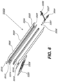
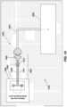
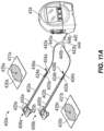
- FIGS. 4A-6 illustrate embodiments of a negative pressure wound treatment system 5501 similar to the embodiment illustrated in FIG. 1 .
- the system 5501 may comprise a flexible suction adapter 5500 having a bridge portion 5502 with a proximal end 5503 and a distal end 5505, and an applicator 5520 at the distal end 5505 of the bridge portion 5502 forming the flexible suction adapter 5500.
- a connector 5504 is preferably disposed at the proximal end 5503 of the bridge portion 5502, so as to connect to at least one of the channels 5512 and/or 5516, as shown in FIG. 4B .
- a cap 5536 may be provided with the system 5501 (and can in some cases, as illustrated, be attached to the connector 5504).
- the cap 5536 can be useful in preventing fluids from leaking out of the proximal end 5503.
- the system 5501 may include a source of negative pressure such as a pump or negative pressure unit 5534 capable of supplying negative pressure.
- the pump also preferably comprises a canister or other container for the storage of wound exudates and other fluids that may be removed from the wound.
- this pump 5534 may be the pump 200 described in relation to FIG. 2 .
- this pump 5534 can be a RENASYS GO pump, as sold by Smith & Nephew.
- the pump 5534 may be connected to the connector 5504 via a tube 5540.
- the applicator 5520 is placed over an aperture 5535 formed in a drape 5531 that is placed over a suitably-prepared wound 5530, which may in some cases be filled with a wound packing material such as foam or gauze. Subsequently, with the pump 5534 connected via the tube 5540 to the connector 5504, the pump is activated, thereby supplying negative pressure to the wound. Application of negative pressure may be applied until a desired level of healing of the wound 5530 is achieved.
- the bridge portion 5502 may comprise an upper channel layer 5512 positioned between an upper layer 5510 and an intermediate layer 5514, with a lower channel layer 5516 positioned between the intermediate layer 5514 and a bottom layer 5518.
- the layers 5510, 5514, and 5518 have elongate portions extending between proximal and distal ends and may be comprised of a material that is fluid-impermeable, for example polymers such as polyurethane. It will of course be appreciated that the layers 5510, 5514, and 5518 may each be constructed from different materials, including semi-permeable materials. In some embodiments, one or more of the layers 5510, 5514, and 5518 may be at least partially transparent. As illustrated in FIG.
- the upper and lower layers 5510 and 5518 may be curved, rounded or outwardly convex over a majority of their lengths.
- the layers 5510, 5514, and 5518 may be pinched together to weld or adhere the layers together.
- the proximal ends of the channels 5512 and 5516 may be sandwiched between these layers, thus partially compressing the proximal ends of the channels 5512, 5516 and stretching the layers 5510, 5514, 5518 over these aforementioned proximal ends.
- the proximal ends of the materials used in the bridge portion 5502 may not necessarily be rounded or curved; as shown in FIG. 6 , they can remain substantially squared off and straight.
- the upper and lower channel layers 5512 and 5516 are preferably elongate layers extending from the proximal end 5503 to the distal end 5505 and may each preferably comprise a porous material, including for example open-celled foams such as polyethylene or polyurethane.
- one or more of the upper and lower channel layers 5512 and 5516 may be comprised of a fabric, for example a knitted or woven spacer fabric (such as a knitted polyester 3D fabric, Baltex 7970.RTM., or Gehring 879.RTM.) or a nonwoven material. Suitable materials may also include terry-woven or loop-pile materials.
- the fibers may not necessarily be woven, and can include felted and flocked (including materials such as Flotex.RTM.) fibrous materials.
- the materials selected are preferably suited to channeling wound exudate away from the wound and for transmitting negative pressure and/or vented air to the wound site, and may also confer a degree of kinking or occlusion resistance to the channel layers 5512 and 5516 as described below.
- the upper channel layer 5512 may comprise an open-celled foam such as polyurethane, and the lower channel layer may comprise a fabric as described herein.
- the upper channel layer is optional, and the system may instead be provided with an open upper channel. In the embodiment illustrated in FIG.
- the upper channel layer 5512 may have a curved, rounded or upwardly convex upper surface and a substantially flat lower surface
- the lower channel layer 5516 may have a curved, rounded or downwardly convex lower surface and a substantially flat upper surface
- the fabric may have a three-dimensional (3D) structure, where one or more types of fibers form a structure where the fibers extend in all three dimensions.
- 3D three-dimensional
- Such a fabric may in some cases aid in wicking, transporting fluid, and/or transmitting negative pressure.
- To prevent the channels 5512 and/or 5516 from being displaced or twisted while encased in the system 5501--which may impair performance of the respective channels under negative pressure--it may in some embodiments be preferable to adhere or otherwise secure the channels 5512 and/or 5516 to one or more of the layers 5510, 5514, and 5518.
- these materials remain open and capable of communicating negative pressure to a wound area under the typical pressures used in negative pressure therapy, for example between 40 to 150 mmHg, although higher and lower values are possible.
- the fabric may comprise several layers of material stacked or layered over each other, which may in some cases be useful in preventing the channel 5516 from collapsing under the application of negative pressure.
- the fabric used in channel 5516 may be between 1.5 mm and 6 mm; more preferably, the fabric may be between 3 mm and 6 mm thick, and may be comprised of either one or several individual layers of fabric.
- the channel 5512 may be between 1.2-3 mm thick, and preferably thicker than 1.5 mm.
- the materials used in the system 5501 are preferably conformable and soft, which may help to avoid pressure ulcers and other complications which may result from a wound treatment system being pressed against the skin of a patient. Further examples of 3D fabrics are discussed below in FIGS. 7A-C .
- the distal ends of the layers 5510, 5514, and 5518 and the channel layers 5512 and 5516 are enlarged at their distal ends (to be placed over a wound site), and may form a "teardrop" or other enlarged shape.
- the distal ends of at least the layers 5512, 5514, 5516, and 5518 may also be provided with at least one through aperture. This aperture may be useful not only for the drainage of wound exudate and for applying negative pressure to the wound, but also during manufacturing of the device, as these apertures may be used to align these respective layers appropriately.
- a channel connector 5506 is provided at the proximal end 5503 of the bridge portion 5502, the channel connector 5506 preferably being configured so as to be embedded into the lower channel layer 5516 so as to create a secure fluidic connection.
- the channel connector 5506 may in some embodiments be inserted into a pre-made cavity formed into the channel 5516; as illustrated in FIG. 6 , this cavity can be cut out or can be in the form of a rabbet joint.
- the channel connector 5506 may be one of the connectors described in FIGS. 8A-B below.
- the other end of the channel connector 5506 may be connected or in communication with, in one embodiment, a connector tube 5507, although in some embodiments the channel connector 5506 may be connected directly to the connector 5504, or else connected directly to a tube 5540 connected to a source of negative pressure.
- a connector tube 5507 the resulting assembly can permit a connector 5504 to be attached thereto.
- a cap 5536 which may be secured to the suction adapter for example via a cap leash 5527 secured with a ring disposed on the outer surface of the connector tube 5507.
- the cap 5536 may be used to cover the end of the suction adapter, for example at the connector 5504, so as to prevent exudate and other wound fluids from leaking out.
- the connector 5504 is preferably configured to connect with a tube 5540 connected to a source of negative pressure.
- the connector 5504 may for example comprise a lip or other such structure to aid in securing the connector 5504 to a tube 5540 and/or cap 5536, although it will be understood that other connector types are possible, including quick-disconnect couplings, luer locks, Christmas-tree, and other such connectors.
- the upper layer 5510 may comprise additional material extending downward, preferably at least of the thickness of the bridge portion 5502; this material may then be used to bond or weld to the other layers so to form a fluid-tight seal. More specifically, during assembly, the upper layer 5510 may be attached, for example by melting, welding, or with adhesives, to the lower layer 5518 so as to form a fluid-tight seal (with the exception of the apertures at the distal and proximal ends). Preferably, the middle layer 5514 is attached to the top layer 5510 and the bottom layer 5518.
- the connectors 5504 and/or 5506, as well as the tube 5507 may be preferable to attach or bond to at least one of the layers 5510, 5514, 5518 so as to create a fluid-tight connection.
- some embodiments may also be provided with a weld 5532 made onto the lower layer 5518.
- the lower channel 5516 may have a hole or aperture made through it, which may be used to weld it, via the weld 5532, to the lower layer 5518. This welding of the lower channel 5516 to the lower layer 5518 via the weld 5532 made through the hole 5533 may thus aid in preventing the various layers and channels from shifting or being displaced.
- other securement means may be used, for example adhesives and the like, and that such arrangements may be also be used in the upper channel 5512.
- a controlled air leak 5524 may be disposed on the bridge portion 5502, for example at the proximal end thereof.
- This air leak 5524 may comprise an opening or channel extending through upper layer 5510, such that the air leak 5524 is in fluidic communication with the upper channel 5512.
- the air leak 5524 preferably comprises a filter 5525.
- the air leak 5524 is located at the proximal end of the bridge portion 5502 so as to minimize the likelihood of wound exudate or other fluids coming into contact and possibly occluding or interfering with the air leak 5524 or its filter 5525.
- this filter 5525 is a microporous membrane capable of excluding microorganisms and bacteria, and which may be able to filter out particles larger than 45 ⁇ m.
- the filter 5525 can exclude particles larger than 1.0 ⁇ m, and more preferably, particles larger than 0.2 ⁇ m.
- some embodiments may provide for a filter 5525 that is at least partially chemically-resistant, for example to water, common household liquids such as shampoos, and other surfactants.
- reapplication of vacuum to the suction adapter 5500 and/or wiping of the exposed outer portion of the filter 5525 may be sufficient to clear any foreign substance occluding the filter 5525.
- the filter 5525 may be composed of a suitably-resistant polymer such as acrylic, polyethersulfone, or polytetrafluoroethylene, and may be oleophobic and/or hydrophobic.
- the filter 5525 may also comprise a supporting backing layer, for example a nonwoven polyester support.
- the air leak 5524 will supply a relatively constant air flow that does not appreciably increase as additional negative pressure is applied to the system 5501. In embodiments of the suction adapter 5500 where the air flow through the air leak 5524 increases as additional negative pressure is applied, preferably this increased air flow will be minimized and not increase in proportion to the negative pressure applied thereto.
- the filter 5525 provided in the controlled air leak 5524 in certain embodiments may be useful in a system 5501 for use with more ambulatory and active patients.
- a chemically-resistant filter may permit a patient to bathe or shower without damaging the filter's functionality when reconnected to a source of negative pressure. Any occlusion or fluid blocking the air leak 5524 could then be cleared by, for example, wiping off the filter 5525 or re-applying negative pressure to the suction adapter 5500.
- Such a system would also have the advantage that the system 5501 and any assorted wound dressing materials, if present, would not need to be removed and then re-applied should a patient need to be disconnected from the source of negative pressure, for example incidental to bathing. This would entail significant advantages in improving the cost-effectiveness and ease of use of the present treatment system.
- the suction adapter 5500 is preferably constructed so as to provide a consistent fluid flow even if the suction adapter 5500 is kinked or weighted down.
- the bridge portion 5502 may become folded over itself, or else the patient may roll over, thus placing his or her weight over at least a portion of the suction adapter 5500.
- prior art dressings and fluidic connectors become blocked or ineffective in such situations and in some cases may contribute to complications such as pressure ulcers.
- certain embodiments provide for improved blockage resistance if kinked or weighed down.
- the suction adapter 5500 is able to maintain a flow rate through the air leak 5524 of at least 0.08 L/min, and preferably 0.12 L/min while negative pressure is applied through a source of negative pressure.
- Further embodiments also provide for the suction adapter 5500 to be able to handle fluid exudate drainage from the wound site through the lower channel 5516 of at least 10 L/day, or 6.9 ml/min.
- Certain embodiments provide for the suction adapter 5500 to maintain these flow rates with a weight, for example a 12 kg weight, pressing down on the bridge portion through a rod with a 1 in. diameter.
- these flow rates are also maintained while the bridge portion 5502 is kinked over itself with the same weight, or for example with a 4.75 kg weight placed directly on the folded region. It is preferable that the suction adapter 5500 be able to withstand being folded or kinked over even during an extended period of time, for example over 40 hours, and not show any degradation in performance (e.g., flow rates) compared to its performance prior to being folded or kinked over. Preferably, embodiments of the suction adapter 5500 are also able to transmit and maintain a negative pressure at the wound that is close to the negative pressure level at the source of negative pressure.
- an acceptable level of pressure maintained at the wound may be within +-.25 mmHg of the negative pressure set at the source of negative pressure, with this pressure being preferably maintained at this level within 95% of the time that the suction adapter 5500 has negative pressure applied to it.
- Acceptable pressure levels may include pressure ranges between 40-120 mmHg, although levels of 200 mmHg have successfully been used.
- the suction adapter 5500 also comprises an applicator 5520 designed for placement over a wound site.
- the applicator 5520 comprises a flexible layer 5550, for example polyethylene or polyurethane, with a layer of adhesive on its lower (wound-facing) side.
- a protective release layer 5529 may be placed on the adhesive layer, which is removable before use.
- a more rigid removable backing layer 5552 may be provided on the upper side of the applicator 5520 to facilitate handling of the applicator 5520 due to the flexibility of the layer 5550.
- the applicator 5520 preferably comprises an attachment point for the bridge 5502 at the distal end 5505, for example using a section of double-sided adhesive tape 5528.
- the double-sided adhesive tape 5528 may be protected by an additional protective release layer, which is removed prior to adhering the bridge 5502 to the applicator 5520.
- attachment methods are also contemplated, for example heat sealing, welding, or suitable adhesives. Some embodiments may also permit the manufacture of the bridge 5502 and the applicator 5520 as a single unit that does not require separate attachment means.
- the applicator 5520 preferably comprises at least one aperture 5526 through itself and designed to be placed over a wound site, and which can serve to fluidically connect the wound site to the source of negative pressure and to the air leak while also serving as a conduit to draw out wound exudate from the wound site.
- the system 5501 may be used in a similar fashion to the other embodiments previously disclosed herein, such as the system 100 described in relation to FIG. 1 .
- a wound site 5530 is preferably cleaned and prepared in a suitable fashion, and a wound packing material, if necessary, placed into the wound site, followed by a drape 5531.
- An aperture 5535 through the drape to the wound site is then created, although some embodiments may have a pre-made aperture 5535. Subsequently, an operator may situate the applicator portion 5520 over the aperture 5535.
- a fluidic conduit such as a tube 5540 may then be connected to the connector 5504.
- the tube 5540 may also be connected to connector 5504 prior to applying the applicator to the wound site.
- the fluidic conduit is connected to a source of negative pressure 5534, preferably with a container suitable for containing wound exudate interposed therebetween. The application of negative pressure may then be effectuated to the wound site 5530 until the wound site progresses to a desired level of healing.
- wound exudate from the wound site 5530 is drawn by the negative pressure through the lower channel layer 5516.
- the air leak 5524 allows air to pass through the upper channel layer 5512 into the apertures through the distal ends of the layers 5512, 5514, 5516 and 5518.
- the negative pressure draws air passing through the upper channel layer into the lower channel layer 5516 back toward the source of negative pressure or pump.
- the controlled air leak 5524 provides a constant flow of air through the suction adapter 5500, which then may be used to determine whether blockage or leakage is present.
- causes of blockage can include, for example, situations where the lower channel 5516 becomes occluded with wound debris.
- Leakage causes can include, for example, improper sealing of the drape over the wound site, or physical damage to the suction adapter 5500 leading to excess air leaking into the system.
- the blockage or leakage may be determined, in certain embodiments, by measuring the speed of the pump while the pump works to maintain a constant negative pressure. Pump speed may also be measured indirectly by measuring the amount of voltage or signal sent to the pump.
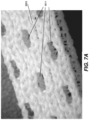
- FIGS. 7A-C illustrate views of a 3D fabric that may be used in various embodiments described herein, for example the bridge portion 5502 of the suction adapter illustrated in FIGS. 4A-6 .
- porous materials such as foam may be used in the embodiments described herein, for example in the upper and lower channels 5512 and/or 5516 illustrated in FIGS. 5B-C .
- the use of 3D fabrics may be advantageous in some circumstances.
- Certain 3D fabrics have been found to perform well in conveying negative pressure to and wound exudate from a fluidic suction adapter, even while under compression--for example when a patient's weight is placed directly upon the suction adapter, or when negative pressure is applied and/or when the fluidic suction adapter is kinked or folded.
- 3D fabrics that have been found to perform acceptably include knitted polyester 3D fabric, Baltex 7970.RTM., Gehring 879.RTM., or Coolmax.RTM..
- other fibers and fabric types may be used in part or in whole to make 3D fabrics, and include without limitation polyamides such as nylon, viscose, cotton, as well as other synthetic microfibers.
- 3D fabrics may also be constructed at least in part from fibers such as Nomex.RTM. and Kevlar.RTM.. Other types of fabrics and materials disclosed elsewhere herein may also be used.
- the 3D fabric may comprise a bottom side 5603, a top side 5605, and an open middle area 5607.
- FIG. 7A illustrates the bottom (wound-facing) side 5603 of a 3D fabric, which may be woven so as to create oblong or ovoid openings 5611 extending lengthwise across the fabric.
- the oblong or ovoid openings 5611 represent or provide an open area of between 10 and 45% (or about 10% to about 45%) of the surface area of the bottom layer, more preferably 10% to 30% (or about 10% to about 30%).
- fibers are knitted (for example by warp knitting) so as to also include these larger openings or pores that permit bulk transport of wound fluids in addition to wound fluids carried along the fibers by capillary action of the fibers. Apertures that are optionally formed in the distal end of the 3D fabric (as illustrated in FIGS. 5B and 6 ) may also aid in the bulk evacuation of wound debris and fluids.
- FIG. 7B illustrates the top side 5605 of a 3D fabric that may be used as described herein.
- This top side 5605 in one embodiment does not have the larger ovoid apertures 5611 of the bottom side 5603, but may have openings 5613 defined by fibers extending lengthwise and generally transversely or at an angle across the width of the fabric. As illustrated, these openings are generally rhombus-shaped. In one embodiment, these openings 5613 may represent or provide an open area greater than that of the bottom layer, for example between 30% and 50% (or about 30% and about 50%).
- the fabric presented here is a non-limiting example, and different fabric configurations and orientations are possible, for example with the top side 5605 being placed downward so as to face the wound and with the bottom side 5603 facing upward.
- FIG. 7C illustrates a cross-section of a 3D fabric (the bulb-like projections on the vertical fibers in the fabric are an artifact of the cutting process).
- the vertically extending fibers 5609 may be woven so as to extend through the middle open area 5607 while also being connected to the bottom and top layers 5603 and 5605.
- the fibers 5609 present in the open middle layer 5607 will have sufficient stiffness so as to help prevent compression of the fabric.
- 3D fabrics that have been found to perform well will often include a larger open area 5607 in the middle portion that may permit exudates and other fluids to be effectively transported away from a wound site while under the application of negative pressure, while more densely-woven outer layers 5603, 5605 may aid in providing additional tensile strength and capillary wicking action.
- the middle layer may include an open volume of greater than 50% (or greater than about 50%).
- the resulting fabric cannot be too thick or composed of fibers that are too stiff, as the resulting suction adapter and system may not remain sufficiently flexible for comfortable usage with a patient.
- the flow rate of exudate through the fabric may be simplified by considering the porosity of the fabric.
- the porosity of the fabric and thus the space that will be available for fluids to travel through, may be determined in part by the knit pattern of the fibers used in creating the 3D fabric, the thickness of the fibers used therein, and their respective stiffness and hardness (especially when under compression). Fibers may also be modified by surface properties (the fibers can be flat or textured) and the number of fibers or filaments used in the resulting fabric.
- Compression resistance may be affected by the choice of fiber or monofilament used in the vertical axis of the fabric, and generally, a stiffer material will improve compression resistance on this axis. Other materials properties, such as hydrophobicity, may play a role.
- Preferred embodiments of the 3D fabric used with certain suction adapters have been found to work well when Baltex.RTM. fabric is treated in such a fashion.
- Other possible treatments may include lipophilic coatings to prevent proteins from adhering and building up during use, which may cause clogging and loss of pressure to the wound site.
- the flow rate through the 3D fabric while under the application of negative pressure may be approximated by considering each opening as a separate orifice plate subject to Bernoulli's principle while under laminar flow. To simplify calculations, the area of openings for a given area of 3D fabric may be used. Thus, the 3D fabric may be optimized to achieve a good balance between factors such as the compression resistance required and the resulting flow rate under the application of negative pressure. Further optimization will also take place with the stiffness and flow rate of the 3D fabric being tailored to application in the embodiments described herein.
- the 3D fabric should preferably be designed so as to yield when compressed against tissue, thereby preventing tissue compression (for example against bony prominences in the patient) and the discomfort and damage, such as pressure ulcers, that may follow.
- the dimensions of the fabric may be tailored for the ultimate use of the suction adapter--smaller in the case of distal extremities such as fingers, and larger for abdominal and burn wounds. A fabric that is too stiff may also cause pressure ulcers and other such complications, although it may function acceptably in larger dimensions.
- flow rates through embodiments of the suction adapter using 3D fabrics are at least 0.08 L/min, preferably up to 10 L/min during the application of negative pressure, and should be able to handle fluid exudate drainage of at least 10 L/day.
- Some embodiments of the suction adapter may be configured to handle much larger wounds, including abdominal wounds, and which in some cases may exude at least 0.5 L/hr, or 12 L/day.
- the pump used for example, the RENASYS EZ
- the RENASYS EZ may be able to evacuate up to 16 L/min, thereby evacuating a large wound to a negative pressure level of 120 mmHg in less than a minute.
- the pressure drop calculated due to the 3D fabric should be minimal, and the level of negative pressure measured at a wound site is preferably within 25 mmHg of the pressure level measured at the source of negative pressure.
- the pressure drop increases as the negative pressure applied increases (thus rendering the 25 mmHg target more difficult to reach)
- embodiments of the wound treatment system are preferably able to maintain this target pressure to at least a negative pressure of 200 mmHg.
- the suction adapter and system are preferably able to function within pressure ranges required for negative pressure, which are estimated to be from around 40 mmHg to 200 mmHg. Pressure ranges greater than 200 mmHg are possible, but these may in some circumstances cause patient discomfort.
- the apparatus may also function at lower pressure ranges, such as 20 mmHg, although at such low pressure levels the therapeutic effects resulting from negative pressure may be diminished, with the device acting more as a drainage device.
- embodiments of a negative pressure treatment system are able to maintain these target pressures at the wound site within 95% of the time that negative pressure is being applied to the wound.
- the fabric may comprise several layers of material stacked or layered over each other, which may in some cases be useful in preventing the channel 5516 from collapsing under the application of negative pressure.
- the fabric used in channel 5516 may be between 1.5 mm and 6 mm; more preferably, the fabric may be between 3 mm and 6 mm thick, and may be comprised of either one or several individual layers of fabric. In other embodiments, the channel 5512 may be between 1.2-3 mm thick, and preferably thicker than 1.5 mm.
- the 3D fabric is able to withstand a load of at least 5.3 psi with a compression of not more than 10% of the fabric's original thickness. Further, the 3D fabric may also be able to resist compression to less than half of its original thickness when subjected to a load of 15 psi.
- a 3D fabric may be woven from 100% polyester using yarns of 150 and 225 Denier, to yield a fabric weighing approximately 23 to 25 oz per square yard. In these cases, the fabric may be approximately 5.8-6.8 mm thick.
- the bottom portion of the fabric may also have several openings or pores 5611 similar to those illustrated in FIG. 7A , which may be elongated, rectangular or ovoid in shape and oriented with their long axis lengthwise along the fabric.
- the openings 5611 may be arranged in a plurality of rows extending lengthwise across the fabric, for example 2 to 5 rows, or more preferably 3 rows as illustrated in FIG. 7A .
- the openings 5611 may be spaced equidistantly from each other in each of the rows, and may form a staggered pattern from one row to another.
- each row may have approximately 6-10 openings, more preferably 8 openings, per 2 inches (or about 50 mm).
- the transverse rows formed by the openings may have a spacing of approximately 6-10 openings, more preferably 8 openings, per 21/8 inches (or about 54 mm).
- the openings may have a length of between about 1/16" to about 1" lengthwise, and a width of between about 1/32" and 1/2 "widthwise.
- the openings measure approximately 1/8" (or about 3.2 mm) lengthwise and 1/32" (or about 0.79 mm) across.
- the 3D fabric in one embodiment may have an overall length of between about 50 and 100 mm, more preferably about 60 mm, a width between about 5 and 15 mm, more preferably about 9 mm, and a thickness of about 6 mm.
- Embodiments of the systems described herein have been tested and found to perform satisfactorily. Such testing was performed by constructing suction adapters from embodiments described herein. The distal ends of the suction adapters were then placed over an aperture made onto a drape placed over a simulated wound cavity provided with a source of simulated wound fluid, which was controllable and which can vary the flow rate of the wound fluid.
- the simulated wound cavity was also in some cases packed with foam or some other wound packing material.
- the simulated wound fluid was a 5:1 water to glycerol mix, and in others filtered horse serum (available from Oxoid, United Kingdom) was used.
- the proximal end of the suction adapter was then connected to a source of negative pressure, in this case a pump. Flow rate tests and other measurements were then conducted at various negative pressure ranges and simulated exudate flow rates and air leak rates.
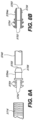
- FIG. 8A illustrates an embodiment of a connector 5704, similar to the connector 5506 described previously, and which may be used to securely connect a source of negative pressure to a channel 5716 of a suction adapter such as the ones described herein.
- this channel 5716 may be the upper channel 5512 or, more preferably the lower channel 5516 in FIGS. 55-56.
- such connectors 5704 may be useful in providing a more secure connection from the source of negative pressure to a negative pressure treatment system.
- the use of these connectors 5704 is optional, and may not be necessary in all embodiments described herein.
- a tube 5740 connected to the connector 5704 may pull, or other external forces may somehow disengage the connector 5704 away from the channel 5716 to which it is attached. In such situations, application of negative pressure to the wound may be reduced or stopped.
- Further means to secure the connector 5704 to the remainder of the system may, as described above, include bonding or attaching other layers of the treatment system, if present, to the connector 5704.
- the connectors 5704 may be designed so as to create a secure connection with a fabric or material used in a channel; when 3D fabrics or 3D knitted materials are used, some embodiments of the connector 5704 are configured to engage with or attach to a portion of the material or fibers of the material to create a more secure connection.
- embodiments of the connector 5704 are able to withstand a pulling force of up to 20 kg before disconnection and/or failure of the connector occurs, preferably such that the connector disengages from the channel it is connected to. It will be understood that other embodiments may be configured to withstand a lower pulling force, and may be tailored to release so to prevent injury to a patient (for example, constriction of the suction adapter and/or drainage tubes around a limb).
- FIG. 8B illustrates an embodiment of the connector 5704a comprising two or more projections 5752 extending distally lengthwise from the preferably cylindrical main body of the connector 5704a.
- the main body also comprises a central channel 5755 extending lengthwise through the main body of the connector 5704a.
- the projections 5752 may additionally comprise one or more barbs 5754 attached thereto.
- these barbs 5754 are angled proximally so as to act as anchors when pushed or inserted into the channel 5716.
- the barbs 5754 are configured to engage to the fibers therein, creating a more secure connection.
- a lip 5756 which may be provided in a frustoconical form, may also be provided for connection to a tube 5740.
- the tube 5740 may be connected to the connector 5704a (as well as the other connectors described herein) for example by press-fitting, although other connections means are possible.
- the tube 5740 may be the same as tube 5507 in FIG. 6 , or it may be any other tube used to provide fluid communication with a source of negative pressure. It will also be appreciated that the features of these connectors, particularly at the distal ends, can be incorporated onto the ends of tubes used to communicate negative pressure, such that those tubes can be directly connected to the suction adapter system.
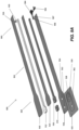
- FIGS. 9A-C illustrate an embodiment of a flexible suction adapter 900 similar to the embodiments of the flexible suction adapter 5500 illustrated in and described in relation to FIGS. 4A-8B .
- FIG. 9A illustrates an exploded view of the suction adapter 900
- FIG.9B illustrates a top view of the suction adapter 900.
- FIG. 9C illustrates a cross-sectional view of the suction adapter 900.
- the suction adapter 900 may include a bridge portion 902 having a proximal end 903 and a distal end 905 and an applicator 920 at the distal end 905 of the bridge portion 902, forming the flexible suction adapter 900.
- the flexible suction adapter is constructed in a similar fashion to the flexible suction adapter 5500, and the bridge portion 902 may be constructed from a similar dual layer arrangement as previously described.
- the bridge portion 902 may include an upper channel layer 912 positioned between an upper layer 910 and an intermediate layer 914, with a lower channel layer 916 positioned between the intermediate layer 914 and a bottom layer 918.
- a controlled air leak 924 may be disposed on the bridge portion 902, for example adjacent the proximal end thereof.
- This air leak 924 may comprise an opening or channel extending through upper layer 910, such that the air leak 924 is in fluidic communication with the upper channel 912.
- the air leak 924 may include a filter 925.
- the applicator 920 preferably comprises an attachment point for the bridge portion 902 at the distal end 905, for example using a section of double-sided adhesive tape 928. It will be understood that different attachment methods are also contemplated, for example heat sealing, welding, or suitable adhesives.
- a connector 904 may be disposed at the proximal end 903 of the bridge portion 902, so as to connect to at least one of the channels 912 and/or 916.
- a cap 936 may be provided with the suction adapter 900 (and can in some cases, as illustrated, be attached to the connector 904).
- a channel connector 906 may be provided at the proximal end 903 of the bridge portion 902, the channel connector 906 preferably being configured so as to be embedded into the lower channel layer 916 so as to create a secure fluidic connection.
- the other end of the channel connector 906 may be connected or in communication with, in one embodiment, a connector tube 907, although in some embodiments the channel connector 906 may be connected directly to the connector 904, or directly to a tube connected to a source of negative pressure.
- Each of the components of the suction adapter 900 may be similar with each corresponding components of the suction adapter 5500, therefore description of each corresponding components of the suction adapter 5500 previously herein also applies to each components of the suction adapter 900, except as noted below.
- an upper fluid passage may be defined by and between the upper layer 910 and the intermediate layer 914.
- the upper layer 910 and the lower layer 918 extends further at the distal end 905 than the intermediate layer 914, such that the upper fluid passage may be also partially defined between the upper layer 910 and the lower layer 918.
- the upper fluid passage may include the upper channel spacer layer 912.
- the lower fluid passage may include the lower channel spacer layer 916.
- the upper channel spacer layer 912 may also extend further at the distal end 912 than the intermediate layer 914 and the lower channel spacer layer 916 to support the upper layer 910.
- the distal ends of the layers 910, 914, and 918 and the channel layers 912 and 916 are enlarged at their distal ends (to be placed over a wound site), and may form a "teardrop" or other enlarged shape.
- the distal ends of at least the layers 912 and 916 may also be provided with at least one through aperture.
- the upper fluid channel may further include an auxiliary spacer layer 970 placed under the distal end of the upper channel spacer layer 912 and distally of the distal end of the lower channel spacer layer 916, such that the auxiliary spacer layer 970 supports the distal end of the upper channel spacer layer 912.
- the auxiliary spacer layer 970 may include one or more apertures, which may be aligned with the one or more apertures at the distal end of the spacer layer 912.
- the suction adapter 900 includes two apertures at the lower layer 918: an air leak channel aperture 952 and the suction aperture 954, both formed at the lower layer 918, for example at the enlarged distal end of the lower layer 918.
- the air leak aperture 952 and/or the suction aperture 954 may be formed as multiple smaller holes.
- the apertures 952 and 954 may be spaced apart, with aperture 954 located proximally of aperture 952. These apertures may both be located on a central longitudinal axis of the lower layer 918, or one or both apertures may not be located on the central longitudinal axis.
- the applicator 920 may have two openings 962 and 926 configured to be aligned with the air leak channel aperture 952 and the suction aperture 954.
- the air leak channel aperture 952 may be fluidically connected to the upper fluid channel having the upper channel spacer layer 912, thereby forming an air leak flow extending distally from the air leak 924 to the air leak channel aperture 952. As shown in FIG. 9C , this air leak flow extends through the auxiliary spacer layer 970. Also, the suction aperture 954 may be fluidically connected to the lower fluid channel having the lower channel spacer layer 916, thereby forming a suction flow extending distally from the connector 904 and/or a source of negative pressure.
- the upper layer 910 may form a fluid tight seal with the intermediate layer 914 and/or the lower layer 918, and the intermediate layer 914 may form a fluid tight seal with the lower layer 918, such that the upper fluid channel extending distally from the air leak 924 to the air leak channel aperture 952 may be fluidically separate with the lower fluid channel extending distally from the connector 904 to the suction aperture 954.
- the distal end of the intermediate layer 914 may extend between the auxiliary spacer layer 970 and the lower channel spacer layer 916 and sealed with the lower layer 918, thereby separating the upper fluid channel and the lower fluid channel.
- the upper layer 910, the intermediate layer 914, and the lower layer 918 may be sealed to one another using any means described previously herein, for example by melting, welding, or with adhesives.
- the air leak aperture 952 and the suction aperture 954 may be sufficiently spaced from each other, such that wound exudate pulled to the suction aperture 954 does not enter the air leak aperture 952.
- the upper fluid channel may include a filter (not shown) adjacent the air leak aperture 952 to prevent entering of wound exudate into the upper fluid channel and block the upper fluid channel.
- the filter may be permeable to air to allow the air from the air leak to be provided to the wound dressing, but may be impermeable to liquid or bacteria.
- the filter disposed at the air leak aperture 952 may be similar to the filter 5525 described herein previously.
- the lower fluid channel may include a filter (not shown) adjacent the suction aperture 954.
- the filter may be configured to substantially prevent wound exudate from entering the lower fluid channel.
- the filter may be impermeable to liquids, but permeable to gases, and is provided to act as a liquid barrier and to ensure that no liquids are able to escape from the wound dressing, thereby a canister to collect the wound fluid may not be needed between the suction adapter and a source of negative pressure.
- the filter may be hydrophobic.
- the filter can be attached or sealed to the suction adapter and/or the cover film over the wound dressing.
- the filter may be molded into the suction adapter 900, or may be adhered to the lower layer 918 of the suction adapter 900 using an adhesive such as a UV cured adhesive.
- the auxiliary spacer 970 may be constructed from any flexible material suitable for transmitting air from the controlled air leak.
- the auxiliary spacer 970 may be constructed from any material suitable for the upper channel spacer layers 912, 5512 and the lower channel spacer layers 916, 5516 as described herein previously, for example open-celled foams such as polyethylene or polyurethane, or a fabric such as a knitted or woven spacer fabric (such as a knitted polyester 3D fabric, Baltex 7970.RTM., or Gehring 879.RTM.) or a nonwoven material.
- the double-sided adhesive tape 928 is adhered around the suction apertures 926 and 954, thereby securing the applicator 920 to the lower layer 918.
- the double-sided adhesive tape 928 may be sized and shaped to be adhered around the air leak apertures 952 and 962, or both the apertures 962/952 and 926/954.
- the suction adapter 900 may include an additional double-sided adhesive tape (not shown) similar to the adhesive tape 928, to be adhered around the air leak apertures 952 and 962.
- the applicator may be attached to the lower layer 918 with glue and/or welding.
- FIGS. 9A-C provides for an air leak path extending into the wound dressing that is fluidically separated from the suction flow path extending from the wound dressing to the source of negative pressure.
- This embodiment differs from the embodiment of FIGS. 5A-6 , where the air leak path fluidically connects with the suction flow path above the wound dressing.
- the negative pressure source may continue to operate and draw air from the suction adapter by drawing air from the air leak.
- FIGS. 9A-C illustrates an example of the flexible suction adapter 900 having a fluidically separate or isolated air leak channel (the upper fluid channel) and suction channel (the lower fluid channel)
- the air leak channel and the suction channel may be disposed side-by-side, instead of one channel being placed on top of the other.
- two physically separated soft tubes may be connected to the wound bed, wherein one tube would act solely as a means to allow transmission from the source of negative pressure and the other tube solely act as an air leak channel to allow air from the controlled air leak to flow into the wound.
- FIG. 10 illustrates a diagram of a system 1000 for applying negative pressure according to some embodiments, for example utilizing the suction adapter 900 or any suction adapters having a separated air leak path.
- the system 1000 includes a source of negative pressure 1022 in fluidic connection with the wound dressing 1006, via fluid flow path 1040, so as to supply negative pressure to one or more wound sites.
- the fluid flow path 1040 includes a suction adapter 1020 and a tube 1042, which are connected by a connector 1052.
- the suction adapter 1020 also includes an air leak 1012 configured to admit air into the suction adapter 1020.
- the suction adapter 1020 includes a calibrated leak path 1026 and a suction path 1024.
- the suction path 1024 is fluidically connected to the fluid flow path 1040 through the connector 1052, so as to supply negative pressure to the wound site through the wound dressing 1006.
- the calibrated leak path 1026 is fluidically connected to the air leak 1012, so as to supply air from air leak into the wound through the wound dressing 1006.
- the calibrated leak path 1026 and the suction path 1024 may be fluidically connected to each other only through the wound as described herein previously in relation to FIGS. 9A-C .
- the air leak 1012 may be disposed at any suitable location in a fluid flow path.
- the air leak 1012 can be incorporated into the connector 1052.
- the air leaks can be electronically or electromechanically adjusted by a controller of the system to close or widen the leak.
- a controller can communicate with the air leaks to open or close each air leak individually or as a unit.
- the air leaks can be solenoid valves. The communication between the air leaks and the controller can be wired or wireless.
- the suction adapter 1020 is able to maintain a constant leak rate through the air leak 1012 while negative pressure is applied through a source of negative pressure.
- Some embodiments may support an air leak of 1, 2, 3, 4, 5, 6, 7, 8, 9 mL/min or more (+/- .5 mL/min or another suitable deviation).
- Some embodiments may support an air leak of 10, 20, 30, 40, 50, 60, 70, 80, 90 mL/min, or more (+/- a few mL/min or another suitable deviation).
- Some embodiments may support an air leak of 0.1, 0.2, 0.3, 0.4, 0.5, 0.6, 0.7, 0.8, 0.9 L/min, or more (+/- a few centiliters/min or another suitable deviation).
- the leak rate can be discussed in terms of controlled leak pathways (CLPs), where CLP is a suitable constant.
- CLP controlled leak pathways
- an air leak may have a leak rate of 0.25, 0.5, 1, 2, 3, 4, 5, 6, 7, 8, 9, 10, or more.
- a leak rate of 0.1 L/min 1 CLP may correspond to 0.1 L/min
- 5 CLPs may correspond to 0.5 L/min, and so on.
- the negative pressure source must work harder in presence of higher intensity air leak, which can drain the power source faster.
- a relatively low leak rate is chosen.
- FIGS. 11A-11B illustrate a negative pressure wound treatment system 400 according to some embodiments.
- the system 400a, 400b may include a pump assembly or negative pressure unit 434 capable of supplying negative pressure.
- the negative pressure unit 434 is the same as that depicted in FIG. 2 .
- the negative pressure unit 434 may be in fluidic connection with one or more wound dressings 406a, 406b (collectively referred to as 406) so as to supply negative pressure to one or more wounds.
- the fluidic connection between a wound dressing 406 and a negative pressure unit 434 is referred to as a fluid flow path (e.g., the path through which fluid aspirated from a wound via negative pressure flows).
- a first fluid flow path can include components providing fluidic connection from the negative pressure unit 434 to a first wound dressing 406a.
- the first fluid flow path can include the path from the wound dressing 406a to the negative pressure unit 434 or the path from the first wound dressing 406a to an inlet of a branching attachment 444 in fluidic connection with the negative pressure unit 434.
- the system 400 can include a plurality of wound dressings (and corresponding fluid flow paths) in fluidic connection with the negative pressure unit 434 via a plurality of suction adapters such as the suction adapters 900 described in relation to FIGS. 9A-C and/or the suction adapters 1020 described in relation to FIG. 10 .
- the suction adapters for the systems 400a and 400b may include a controlled leak channel fluidically separate of a suction channel.
- Each wound dressing and fluid flow path can include a variety of features or elements which match or are similar to features or elements of another wound dressing or fluid flow path within the system.
- one or more corresponding features or elements may be collectively referred using a reference number without a corresponding letter.
- bridge 402a and bridge 402b may be collectively referred to as bridge 402.
- elements which have been collectively referred to are not identical and can have different features or attributes.
- the system 400a may include a suction adapter such as the suction adapter 900 or 1020, including a bridge 402 having a proximal end 403 and a distal end 405 and an applicator 420 at the distal end 405 of the bridge 402 forming a flexible suction interface or adapter.
- the negative pressure unit 434 can include a canister or other container for the storage of wound exudates and other fluids that may be removed from the wound.
- the negative pressure unit 434 may be the negative pressure unit 5534 described in relation to FIG. 2 .
- the wound dressing 406 may collect the wound exudates and other fluids, and the canister may not be present.
- the negative pressure unit 434 can be a Renasys Touch device, as manufactured by Smith & Nephew. In some embodiments, connectors other than Renasys Soft Port or devices other than Renasys Touch can be used.
- Fig. 11B illustrates an embodiment of Fig. 11A , with the flexible suction adaptor having been placed over a wound.
- the applicator 420 is placed over an aperture 435 formed in a drape 431 that is placed over a suitably-prepared wound 430, which may in some cases be filled with a wound packing material such as foam or gauze.
- the negative pressure unit 434 is activated, thereby supplying negative pressure via the fluid flow paths to the wounds.
- Application of negative pressure may be applied until a desired level of healing of the wounds 430 is achieved.
- the negative pressure unit 434 can provide treatment to more than two wounds in some embodiments.
- negative pressure wound therapy can be provided to a single wound.
- the negative pressure unit 434 may be in fluidic connection with the wound dressings 406 via one or more tubes 440, 442, one or more bridges 402, or via an inlet manifold branching attachment 444.
- the negative pressure unit 434 may be in fluidic connection with a plurality of wound dressings 406 via a tube 440, an inlet manifold branching attachment 444, a tube 442, and a bridge 402.
- the manifold branching attachment 444 can be connected directly to the negative pressure unit 434 without using the tube 440. As illustrated in Figs.
- the inlet manifold branching attachment 444 can be configured to connect the negative pressure unit 434 to a plurality of fluid flow paths via a plurality of dressing conduit attachment portions 445a, 445b.
- the inlet manifold branching attachment 444 can include any number of dressing conduit attachment portions 445 configured to be fluidically connected to a negative pressure attachment portion 446 via a joint.
- the inlet manifold branching attachment can include two dressing conduit attachment portions 445a, 445b, three dressing conduit attachment portions, or more than three dressing conduit attachment portions.
- the plurality of dressing conduit attachment portions 445 can include a first dressing conduit attachment portion 445a and a second dressing attachment portion 445b. However, it will be understood that more or fewer dressing conduit attachment portions can be included in the inlet manifold branching attachment 444.
- Each of the dressing conduit attachment portions 445 includes a shaft extending away from a joint and including an inlet distal the joint. The inlets are configured to fluidically connect at least a portion of a fluid flow path to the negative pressure unit 434.
- the inlet manifold branching attachment 444 can also include one or more negative pressure attachment portions 446.
- Each of the negative pressure attachment portions 446 can include a shaft extending away from the joint and an inlet distal the joint.
- the inlet(s) can be configured to fluidically connect to the negative pressure unit 434.
- the inlets can include male or female non-luer connectors to attach to a corresponding male or female connector of a conduit or pump.
- a negative pressure attachment portion 446 is attached to the negative pressure unit 434 via a tubing 440 or other conduit.
- a negative pressure attachment portion 446 can also be attached directly (or can be integrated with) a housing of the negative pressure unit 434.
- the inlet manifold branching attachment 444 or the conduit can include incorporated one or more valves, clamps, caps, air leaks, or other flow regulator mechanisms which may be configured to admit fluid into a fluid flow path or, alternatively, block or restrict flow or passage of fluid through a fluid flow path.
- valves, air leaks, or other flow regulation mechanisms in the inlet manifold branching attachment 444 can be opened or closed electronically.
- a controller of the negative pressure unit 434 can communicate with the valves, air leaks to open or close each one individually or as a unit. This communication can be wired or wireless.
- the dressing conduit attachment portions 445 can include shafts forming the top portions of a Y- (two wound), W- (three wound) or other shape of the inlet manifold branching attachment.
- the proximal ends of dressing conduit shafts and the distal end of the pump conduit shaft can meet at a joint.
- the joint can include a hinge that allows rotation of the shafts about the joint.
- the inlet manifold branching attachment can be a W-shaped connector (as illustrated in Fig. 6 ). In embodiments such as these, the inlet manifold branching attachment can include three or more dressing conduit attachment portions and one negative pressure attachment portion.
- the inlet manifold branching attachment can include rigid plastic or flexible plastic tubing and can also or alternatively be encased in a soft silicone sleeve to increase patient comfort and prevent the inlet manifold branching attachment 444 from becoming a pressure point.
- the negative pressure unit can aspirate fluid from multiple wounds 430 simultaneously.
- the performance and wound healing capabilities (such as, fluid management) of such system can be equivalent to or exceed that of a standard single wound dressing with single pump set-up.
- an integrated inlet manifold (not shown) can be used in place of an inlet manifold branching attachment 444.
- inlet manifolds can be incorporated (e.g., directly attached) into the negative pressure unit 434 or pump housing such that the one or more fluid flow paths can fluidically connect to the pump via one or more inlets of the integrated inlet manifolds.
- the integrated inlet manifolds can include a splitting attachment (similar to the Y-shaped or W-shaped branching attachment described herein) or can include one or more separately integrated inlets in fluidic connection with the pump.
- the system 400 can apply negative pressure to one or more wounds.
- the level of negative pressure at one or more of the wounds (for example, under one or more wound dressings) can be sufficiently close to the negative pressure level at the source of negative pressure.
- an acceptable level of pressure maintained at the wound may be within ⁇ 1 mmHg, ⁇ 5 mmHg, ⁇ 10 mmHg, ⁇ 25 mmHg of the negative pressure setpoint. In some embodiments, this pressure can be maintained at this level within 95% (or another suitable percentage) of the time that the system 400 has negative pressure applied to it.
- acceptable pressure levels may include pressure ranges between -40 to -120 mmHg. However, other pressure levels may be used as described herein.
- one or more air leaks such as the air leaks 424, 5524, 924, or 1012 in one or more of the fluid flow paths may be utilized to determine one or more operating conditions within the system.
- an air leak can be a controlled air leak that can admit a relatively constant air, gas, or other fluid flow into a fluid flow path.
- the flow into the fluid flow path from an air leak does not appreciably increase as additional negative pressure is applied to the system.
- the presence of an air leak in the system may maintain substantially constant baseline flow through the system when steady state has been achieved (for example, when the negative pressure set point has been reached).
- the system may determine the presence of one or more operating conditions (such as a blockage, leakage, canister full, misalignment of the suction adapter and the like) by monitoring the flow through the fluid flow path(s), which can be measured directly or indirectly based on, for example, monitoring an activity of the negative pressure source.
- one or more operating conditions such as a blockage, leakage, canister full, misalignment of the suction adapter and the like
- each fluid flow path may include an air leak (such as illustrated in Figs. 11A-11B ) and each air leak of a respective fluid flow path can admit a different flow rate of air, gas, or other fluid into the system.
- each air leak of the system can have a different leak rate.
- the leak rate of an air leak can be based at least in part on the size or shape of the air leak, whether the air leak includes a filter, the size or porous level or a filter, a level of occlusion of the air leak or the filter.
- the fluid admitted into a fluid flow path increases the flow rate of that fluid flow path.
- each fluid flow path of the system 400 can have a different flow rate.
- the total flow rate (TFR) of the system 400 e.g., the aggregation of the flow to each of the wound dressings
- TFR total flow rate
- Operating conditions can, for instance, include a "no flow" condition (e.g., all of the flow paths are blocked), a blockage condition of one or more flow paths (e.g., a blockage condition exists in a first fluid flow path, a blockage condition exists a second fluid flow path), a canister full condition, normal operation (e.g., no blockages are present in any of the fluid flow paths).
- the system 400 is capable of providing an indication, such as alarm, to tell the patient or a caregiver an operating status of the system 400 based on a comparison of the determined total flow rate and one or more flow thresholds.
- the flow thresholds corresponding to operating conditions of the system 400 are pre-determined.
- the flow thresholds are based at least in part on dynamic measurements or calculations of the system 400, such as a flow rate or pressure, during a particular mode of the system (e.g., a calibration mode).
- FIG. 12 illustrates a diagram of a system for applying negative pressure according to some embodiments.
- the system 500 includes a source of negative pressure 522 in fluidic connection with wound dressings 506a, 506b via fluid flow path 540d, inlet manifold branching attachment 544, and fluid flow paths 540a, 540b, so as to supply negative pressure to one or more wound sites through suction paths 528a and 528b which are connected with fluid flow paths 540a and 540b respectively.
- the suction path 528a may be connected with the flow channel 540a with the connector 530
- the suction path 528b may be connected with the flow channel 540b with the connector 530.
- first fluid flow path 540a and the second fluid flow path 540b include an air leak 512, 514 configured to admit fluid into controlled air leak path 526a and 526b respectively.
- the controlled air leak path 526a and 526b may be fluidically separated with the suction channel 528a and 528b, such that the controlled air leak paths and the suction paths only fluidically connected through the wound beds.
- the air leaks can be electronically or electromechanically adjusted by a controller of the system to close or widen the leak.
- a controller can communicate with the air leaks to open or close each air leak individually or as a unit.
- the air leaks can be solenoid valves.
- the communication between the air leaks and the controller can be wired or wireless.
- the system 500 or 1000 is able to maintain a constant leak rate through an air leak while negative pressure is applied through a source of negative pressure.
- Some embodiments may support an air leak of 1, 2, 3, 4, 5, 6, 7, 8, 9 mL/min or more (+/- .5 mL/min or another suitable deviation).
- Some embodiments may support an air leak of 10, 20, 30, 40, 50, 60, 70, 80, 90 mL/min, or more (+/- a few mL/min or another suitable deviation).
- Some embodiments may support an air leak of 0.1, 0.2, 0.3, 0.4, 0.5, 0.6, 0.7, 0.8, 0.9 L/min, or more (+/- a few centiliters/min or another suitable deviation).
- the leak rate can be discussed in terms of controlled leak pathways (CLPs), where CLP is a suitable constant.
- CLP controlled leak pathways
- an air leak may have a leak rate of 0.25, 0.5, 1, 2, 3, 4, 5, 6, 7, 8, 9, 10, or more.
- a leak rate of 0.1 L/min 1 CLP may correspond to 0.1 L/min
- 5 CLPs may correspond to 0.5 L/min, and so on.
- the negative pressure source must work harder in presence of higher intensity air leak, which can drain the power source faster.
- a relatively low leak rate is chosen.
- the first air leak 512 has a different leak rate different than the second air leak 514.
- the first air leak can have a leak rate of 1 CLP and the second air leak can have a leak rate of 2 CLP.
- the first air leak can have a leak rate of 0.5 CLP and the second air leak can have a leak rate of 1 CLP.
- the leak rates of system can be any suitable flow rates.
- the first and second fluid flow paths 520a, 520b can have differing flow rates.
- the first air leak 512 and the second air leak 514 can be equal or approximately equal (e.g., +/- 0.1 L/min or another suitable deviation).
- the first air leak 512 and the second air leak 514 can each have a leak rate of 1 CLP.
- the leak rates of system can be any suitable flow rates.
- the first and second fluid flow paths 520a, 520b can have similar flow rates.
- the total flow rate (TFR) of the system is an aggregation of the flow coming from the one or more wound dressings of the system.
- the TFR can be equivalent to the flow rate of fluid flow path 520d.
- the system 500 or 1000 can monitor or determine a TFR in the system based, for example, on monitoring the activity of the negative pressure source 522 or 1022.
- flow rate monitoring can be performed by a pump control processor (such as the pump control processor 370 of Fig. 3 ) alone or in combination with a processor (such as the user interface processor 310 of Fig. 3 ).
- Monitoring the flow rate can be used, among other things, to ensure that therapy is properly delivered to one or more wounds, to detect blockages, canister full conditions, no flow conditions, or leaks in one or more fluid flow paths, high pressure, ensure that the flow rate is not unsafe (e.g., dangerously high).
- the system performs flow rate monitoring directly by, for example, using one or more flow meters positioned in the fluid flow path.
- the system performs flow rate monitoring indirectly by measuring or monitoring activity of the negative pressure source, such as by monitoring the activity of an actuator.
- the system can monitor the activity of a vacuum pump motor, including monitoring the speed of the vacuum pump motor using a tachometer, monitoring current or voltage supplied to the pump (such as, the current or voltage of PWM signal). The system can continuously monitor one or more of these characteristics to determine activity of the negative pressure source.
- a tachometer (such as a Hall effect sensor) can be used to measure the level of activity of pump motor.
- the tachometer can be read periodically, such as every 100 msec or another suitable time period, and periodic readings made over a time duration, such as 32 sec or another suitable time duration, can be combined (e.g., averaged).
- Combined tachometer readings can be used for determining the flow rate, which can in turn be used for leak detection, blockage detection, limiting the maximum flow rate.
- Combined tachometer readings can be converted to a flow rate (e.g., in mL/min) using one or more conversion equations or tables so that a TFR of the system (e.g., an aggregation of the flow in each fluid flow path associated with a wound dressing) is determined.
- the determined flow rate can be compared to various flow rate thresholds, such as one or more blockage thresholds, to determine a presence of a particular condition, such as a blockage, leakage, canister full.
- a total flow rate can be determined for the system.
- TFR can correspond to the sum of the leak rates seen by the negative pressure source.
- an expected TFR can be determined, for instance, in a calibration mode, using one or more conversion equations or tables.
- the expected TFR can correspond to the TFR of the system in steady state operation (for example, when the negative pressure set point has been reached) if no air leaks are present.
- the system can then monitor the TFR and compare it to one or more leak or flow rate thresholds to determine a presence of a particular condition, such as a blockage, no flow, normal operation, canister full.
- the expected TFR can be determined in non-steady state. In certain cases, more than one expected TFR can be utilized.
- a blockage condition is detected when the determined flow rate fails to satisfy one or more flow thresholds.
- a blockage alarm can be enabled if the blockage condition is present for a period of time, such as 30 seconds or another suitable period of time. This approach can implement hysteresis so that transient events do not cause the system to erroneously report presence of one or more operating conditions.
- a different blockage alarm can be enabled for each wound dressing. The blockage alarm can be disabled when the determined flow rate exceeds the one or more flow thresholds.
- the system can differentiate between a blockage in one or more fluid flow paths and canister full conditions.
- blockages and presence of fluid in one or more fluid flow paths are detected by processing data from one or more pressure sensors (not shown), which can be positioned in any suitable location in the flow path.
- a pressure sensor is positioned at or near an inlet of the negative pressure source. This detection can be enhanced by changing one or more settings of the pump, such as increasing pressure level delivered by the pump, decreasing the pressure level, stopping the pump, changing the pump speed, and changing a cadence of the pump.
- flow rate can be estimated as the air, gas, or other fluid volume moving in the fluid flow path per unit of time normalized to standard temperature and standard pressure (e.g., 1 atm).
- Tachometer is short tachometer average (for example, an average of most recent tachometer readings (e.g., over 2.5 seconds or another suitable period of time), which can be measured in Hz) and Slope and Intercept are constants that are based on the negative pressure setpoint.
- the values for Slope and Intercept can be determined for possible pressure setpoints (e.g., -25 mmHg, -40 mmHg, -50 mmHg, -60 mmHg, -70 mmHg, -80 mmHg, -90 mmHg, -100 mmHg, -120 mmHg, -140 mmHg, -160 mmHg, -180 mmHg, -200 mmHg) for a given negative pressure source.
- the flow as a function of the pump speed may not be a best fit as a single line because the pump can be designed to be more efficient at lower flow rates. Because of this, slope and intercept values can be pre-computed for various setpoints and various pumps.
- the determined flow rate can be compared to various flow thresholds to determine a presence of a particular operating condition, such as a blockage condition, no flow condition, canister full condition, abnormal condition, normal condition.
- a fluid flow path can include a pressure sensor at or near a wound dressing 406, at or near an inlet manifold branching attachment 444, or anywhere else on the fluid flow path.
- the pump assembly includes a pressure sensor in or near the inlet (or canister connection) of the pump assembly. This pressure sensor can measure the pressure in the canister (or in or near the dressing in a canisterless system). The pump assembly can continuously measure pressure in the canister, such as every millisecond or any other suitable duration. A suitable number of latest pressure sensor readings can be averaged to mitigate the effects of one or more errant readings.
- the pump assembly can monitor and detect various operating conditions as described herein.
- One or more of these conditions can be detected by, for instance, flow chart 700 or 800 illustrated in FIGS. 13 and 14 .
- a blockage in one or more fluid flow path can be determined by comparing the total flow rate to one or more flow thresholds.
- the comparison can implement hysteresis, such as be continuously or substantially continuously performed over or during a period of time, such as 2 minutes or any other suitable duration.
- the one or more flow thresholds can be selected or determined based on the particular pressure setpoint since the expected TFR may also depend on the setpoint. That is, to detect blockages, the pump assembly can utilize a plurality of flow thresholds corresponding to particular pressure setpoints. Alternatively or in addition, flow thresholds can be selected or determined based on the leak rates of the one or more air leaks. As explained herein, the flow rate can be indirectly determined by detecting and monitoring the pump speed.
- the system determines that there is a blockage in at least one of the fluid flow paths and provides an indication, which can include activating an alarm (e.g., visual, audio, or tactile), pausing operation of the negative pressure.
- an alarm e.g., visual, audio, or tactile
- the pump assembly can determine whether the total flow rate satisfies, exceeds, or falls below a flow threshold during a 2 minute period of time or during any other suitable period of time. Because total flow rate may be updated at periodic time intervals due to periodic sampling of the tachometer, the pump assembly may compare the total flow rate as it is being updated to the flow threshold over the 2 minute period of time.
- Blockage can be detected provided that each total flow rate determined during the 2 minute interval satisfies, exceeds, or falls below a flow threshold. Alternatively or additionally, blockage can be detected if the majority of calculated total flow rates, such as 9 out of 10 or any other suitable number, satisfy, exceed, or fall below a flow threshold. Detected blockages may be cleared when the total flow rate falls below (or exceeds) one or more flow thresholds for a period of time, such as 5 seconds or any other suitable duration.
- the threshold value can be any suitable flow threshold, such as a value selected or determined based on the negative pressure setpoint and expected flow rate in the fluid flow path, which can be determined as described herein.
- one or more flow sensors or flow meters can be used to directly measure the fluid flow.
- the pump assembly can utilize one or more of the techniques described herein in parallel to control the pump and to detect various conditions.
- the pump assembly can be configured to suitably arbitrate between using parameters determined by different techniques. For example, the pump assembly can arbitrate between flow rates determined indirectly, such as based on the pump speed as measured by a tachometer, and directly, such as by using a flow meter.
- the pump assembly can indirectly determine the flow rate and resort to direct determination of the flow rate when needed, such as when indirectly determined flow rate is perceived to be inaccurate or unreliable.
- selecting or activating a Y- or W- connect features for treatment of multiple wounds can alter or modify detection of one or more operating conditions, such as blockages, leaks, canister full condition.
- Activating the Y- or W- connect features can adjust one or more of various thresholds described herein.
- the system automatically detects that Y- or W- connector is present. For instance, if a single wound dressing is connected having a leak rate of 1 CLP, the system can automatically detect that a Y- connector is present by detecting a leak higher than the expected 1 CLP leak. For instance, the system may prompt the user to confirm that another flow path with, for example, with a leak rate of 2 CLP is present.
- the system will know to detect blockage and can determine flow thresholds based at least in part of the determination of the leak rates.
- a similar determination can be used for W-connector with three flow paths. For instance, continuing with the previous example, if the system detects a leak higher than the expected 3 CLP leak, the system can detect that a W-connector is present and may prompt the user to confirm that another flow path with, for example, a leak rate of 4 CLP is present.
- similar approaches can be utilized when more than 3 wounds are being treated.
- Fig. 13 illustrates a flow diagram of a process 700 for determining and indicating one or more operating conditions according to some embodiments.
- the process 700 is implemented by reduced pressure wound therapy system 500, such as by one or more controllers of the system.
- the process 700 determines one or more operating parameters. For example, the process 700 can determine the number of attached wound dressings, whether a fluid flow path corresponding to an attached wound dressings includes an air leak, a leak rate of the one or more air leaks, an expected total flow rate (TFR) of the system, an expected flow rate of each of the fluid flow paths, one or more flow thresholds, a level of activity of the negative pressure source.
- the process 600 can perform one or more of such determinations in a calibration mode. Alternatively, some or all of these determinations can be automatically detected or received by the process upon attachment of each wound dressing.
- a user can input some or all of the operating parameters or the process can perform internal calculations or can utilize conversion equations or tables.
- the process 700 can detect the presence of one or more attached wound dressings by detecting a higher than expected leak rate. For example, the process can automatically detect that a Y- connector is present by detecting a leak higher than the expected leak rate and prompt the user to confirm that another flow path is present. Once the user confirms, the process will determine how to detect a blockage. In other embodiments, the process may detect when a wound dressing is attached and will know the specifications of as air leak based on the attached wound dressing.
- the process 700 can also determine an expected flow rate of each of the fluid flow paths corresponding to each of the attached wound dressings.
- each of the fluid flow paths can include one or more air leaks which can be configured to admit fluid into the fluid flow path in which the air leak is located.
- each of the air leaks may have a different leak rate (e.g., the rate at which fluid is admitted into the fluid flow path). Accordingly, each of the fluid flow paths can have a different expected flow rate.
- the process 700 can determine a plurality of flow thresholds. For example, a process can have two wound dressings, each having a different flow rate. The process can determine a first flow threshold corresponds to a flow rate equal to the aggregation of the expected flow rate of the first fluid flow path and the expected flow rate of the second fluid flow path. A second flow threshold corresponds to the expected flow rate of the second fluid flow path. A third flow threshold corresponds to the expected flow rate of the first fluid flow path. Accordingly, if the monitored TFR satisfies the first flow threshold, then the system is operating normally.
- the process can determine that the first fluid flow path is blocked.
- the process can make this determination because when the flow rate is equal to the expected flow rate of the second fluid flow path, the process is only detecting the flow of the second fluid flow path. As such, the process is not detecting any flow from the first fluid flow path and therefore the process can determine that the first fluid flow path is blocked.
- one or more of the thresholds can be higher or lower to than the expected flow rates to, for example, allow for variability during operation.
- the flow thresholds can correspond to the leak rates of the system.
- a system can have two wound dressings. Each wound dressing can have an associated fluid flow path.
- the first fluid flow path associated with the first wound dressing includes an air leak of 1 CLP.
- the second fluid flow path associated with the second wound dressing includes an air leak of 2 CLP.
- the process 700 can determine a first flow threshold corresponds to a leak rate of 3 CLP, a second flow threshold corresponds to a leak rate of 2 CLP, and a third flow threshold that corresponds to 1 CLP. Accordingly, if the process detects a TFR of 1 CLP (e.g., satisfies the third threshold but does not satisfy the second threshold or third threshold), the process can determine that the second fluid flow path is blocked.
- a TFR of 1 CLP e.g., satisfies the third threshold but does not satisfy the second threshold or third threshold
- the process can make this determination because when TFR is equal to 1 CLP the system is only detecting the flow in the first fluid flow path. As such, the process is not detecting flow from the second fluid flow path and therefore the process can determine that the second fluid flow path is blocked. Similarly, if the process detects TFR of 2 CLP (e.g., TFR satisfies the second threshold and does not satisfy the third threshold), the process can determine that the first fluid flow path is blocked. Likewise, if the process detects TFR of 3 CLP (e.g., TFR satisfies the third threshold), the process can determine that neither the first nor the second fluid flow paths are blocked, and the system is operating normally.
- the process can determine system blockage due to, for example, all fluid flow paths being blocked or canister being full. This is summarized in the following table: Table 1: CLPs are 1 and 2 Flow rate Determination 3 CLP Normal operation 2 CLP First fluid flow path is blocked 1 CLP Second fluid flow path is blocked 0 CLP System blocked
- one or more of the thresholds can be higher or lower to account for inaccuracies.
- the first air leak is equal to 1 CLP
- the first flow threshold provide a small buffer (e.g., 0.03, 0.05, 0.1, 0.15, .2, or 0.25 CLP) such that the threshold is slightly below or slightly higher than 1 CLP. Similar buffers can be used for other flow thresholds.
- the first and second thresholds can be 0.5 and 1 CLP respectively, and the process can make following determinations: Table 2: CLPs are 0.5 and 1 Flow rate Determination 1.5 CLP Normal operation 1 CLP First fluid flow path is blocked 0.5 CLP Second fluid flow path is blocked 0 CLP System blocked
- the process 700 monitors a total flow rate (TFR) utilizing one or more of the flow rate monitoring techniques described herein.
- TFR total flow rate
- the process can suitably arbitrate between flow rates determined using multiple flow rate monitoring techniques if one or more such techniques are executed in parallel.
- the process can execute one of the techniques, such as the flow rate determination based on the pump speed, and utilize one or more other techniques as needed.
- the process can utilize one or more other techniques in cases the determine flow rate is perceived to be inaccurate or unreliable.
- the total rate of flow corresponds to an aggregation of the flow of each of the flow path in the process.
- the total rate of flow can correspond to the aggregation of a flow of the first fluid flow path and a flow of the second fluid flow path.
- the monitored TFR can be compared to an expected TFR to determine if the system is operating normally. Accordingly, by comparing the monitored TFR with the expected TFR (for example, by subtracting the expected TFR from the monitoring TFR), the process 700 can determine a deviation in the current flow rate from the expected flow rate. This deviation can be due to presence of one or more operating conditions.
- the process 700 determines whether the monitored TFR satisfies (for example, is substantially equal to or exceeds) the first flow threshold, which can correspond to expected TFR. If the first flow threshold is satisfied, then, at block 708, the system can indicate the system is operating normally. Indication in block 708 or in any other block of process 700 can be performed using any of the approaches described herein.
- the process 700 transitions to block 710, where it determines whether the monitored TFR satisfies the second flow threshold. If the second flow threshold is satisfied (for example, TFR is substantially equal to or is above the second flow threshold), then, at block 712, the process 700 can indicate a blockage condition exists in the first fluid flow path. The process can make this determination because, based upon determining that the TFR satisfies the second threshold (and does not satisfy the first flow threshold), the process can determine it is only detecting flow from the second fluid flow path.
- the process 700 transitions to block 714, where it determines whether the monitored TFR satisfies the third flow threshold. If the third flow threshold is satisfied (for example, TFR is substantially equal to or is above the third threshold), then, at block 716, the process can indicate a blockage condition exists in the second fluid flow path. The process can make this determination because, based upon determining the TFR satisfies the third threshold (and does not satisfy the first and second thresholds), the process can determine it is only detecting flow from the first fluid flow path.
- the process 700 transitions to block 718, where it determines and indicate that system is blocked.
- the process 700 can include fewer blocks if, for instance, one or more leak rates are equal or approximately equal (e.g., +/- 0.1 L/min or another suitable deviation).
- a system can have two wound dressings and each wound dressing can have an associated fluid flow path.
- the first fluid flow path associated with the first wound dressing can include an air leak of 1 CLP
- the second fluid flow path associated with the second wound dressing can also include an air leak of 1 CLP.
- the process 700 can utilize two flow thresholds: a first flow threshold corresponding to a leak rate of 2 CLP, and a second flow threshold corresponding to a leak rate of 1 CLP.
- the process 700 can determine that either the first or second fluid flow path is blocked.
- the process 700 can make this determination because when TFR is equal to 1 CLP, the process is only detecting the flow from one of the fluid flow paths. In some cases, the process can determine or indicate which fluid flow path is blocked, while in other cases, the process can determine or indicate that a blockage has occurred somewhere in one of the fluid flow paths. If the process 700 detects TFR of 2 CLP (e.g., TFR satisfies the second threshold), the process can determine that neither the first nor the second fluid flow paths are blocked, and the system is operating normally.
- TFR of 1 CLP e.g., satisfies the first threshold but does not satisfy the second threshold
- the process can determine system blockage due to, for example, all fluid flow paths being blocked or canister being full. This is summarized in the following table: Table 3: CLPs are 1 and 1 Flow rate Determination 2 CLP Normal operation 1 CLP Blockage occurred somewhere in the fluid flow paths 0 CLP System blocked
- FIG. 14 illustrates a flow diagram of a process 800 for determining and indicating one or more operating conditions according to some embodiments.
- the process 800 is implemented by reduced pressure wound therapy system 600, such as by one or more controllers of the system.
- the process 800 determines one or more operating parameters. For example, the process can determine the number of attached wound dressings, whether a fluid flow path corresponding to an attached wound dressings includes an air leak, a leak rate of the one or more air leaks, a total leak rate, an expected total flow rate (TFR) of the system, an expected flow rate of each of the fluid flow paths, one or more flow thresholds, a level of activity of the pump. In some embodiments, the process can perform some or all of these determinations in calibration mode. Alternatively, some or all of these operating parameters can be automatically detected or received by the process upon attachment of each wound dressing. In some embodiments, a user can input some or all of the operating parameters or the process can perform internal calculations or can utilize conversion equations or tables.
- the process 800 may detect the presence of one or more attached wound dressings by detecting a higher than expected leak rate. For example, the process can automatically detect that a W- connector is present by detecting a leak higher than the expected leak rate and prompt the user to confirm that another flow path is present. Once the user confirms, the process will know how to detect a blockage. In other embodiments, the process may detect when a wound dressing is attached and will know the specifications of as air leak based on the attached wound dressing.
- the process 800 can determine a plurality of flow thresholds. In this example, the process can determine at least seven flow thresholds. However, it should be noted that more or fewer flow thresholds can be determined. As described with respect to block 702 of Fig. 7 , the flow thresholds can correspond to TFR of the system in presence of one or more operating conditions.
- a first flow threshold corresponds to a flow rate equal to the aggregation of an expected flow rate of the first fluid flow path (expected first flow rate), the expected flow rate of the second fluid flow path (expected second flow rate), and the expected flow rate of the third fluid flow path (expected third flow rate).
- a second flow threshold corresponds to a flow rate equal to the aggregation of the expected second flow rate and the expected third flow rate.
- a third flow threshold corresponds to a flow rate equal to the aggregation of the expected first flow rate and the expected third flow rate.
- a fourth flow threshold corresponds to a flow rate equal to the aggregation of the expected first flow rate and the expected second flow rate.
- a fifth flow threshold corresponds to a flow rate equal to the expected third flow rate.
- a sixth flow threshold corresponds to a flow rate equal to the expected second flow rate.
- a seventh flow threshold corresponds to a flow rate equal to the expected first flow rate.
- the first fluid flow path can have a leak rate of 1 CLP
- the second fluid flow path can have a leak rate of 3 CLP
- the third fluid flow path can have a leak rate of 5 CLP.
- a first flow threshold corresponds to a leak rate equal 9 CLP (e.g., an aggregation of all of the leak rates).
- a second flow threshold corresponds to a leak rate equal to 8 CLP.
- a third flow threshold corresponds to a leak rate equal to 6 CLP.
- a fourth flow threshold corresponds to a leak rate equal to 5 CLP.
- a fifth flow threshold corresponds to a leak rate equal to 4 CLP.
- a sixth flow threshold corresponds to a leak rate equal to 3 CLP.
- a seventh flow threshold corresponds to a leak rate equal to 1 CLP.
- order of the flow thresholds may change based on the leak rate of the air leaks.
- the process 800 monitors a TFR utilizing one or more of the flow rate monitoring techniques described herein.
- the process 800 determines whether the monitored TFR satisfies (for example, is substantially equal to or exceeds) the first flow threshold. If the first flow threshold is satisfied, then, at block 808, the process can indicate the system is operating normally. Indication in block 808 or in any other block of process 800 can be performed using any of the approaches described herein.
- the process transitions to block 810, it determines whether the monitored TFR satisfies (for example, is substantially equal to or exceeds) the second flow threshold. If the second flow threshold is satisfied (and the first flow threshold is not satisfied), then, at block 812, the process can indicate a blockage condition exists in the first fluid flow path. The process can make this determination because, based on the satisfied threshold, the process can determine it is only detecting flow from the second and third fluid flow paths.
- the process transitions to block 814, where it determines whether the monitored TFR satisfies (for example, is substantially equal to or exceeds) the third flow threshold. If the third flow threshold is satisfied (and the first and second flow thresholds are not satisfied), then, at block 816, the process can indicate a blockage condition exists in the second fluid flow path. The process can make this determination because, based on the satisfied threshold, the process can determine it is only detecting flow from the first and third fluid flow paths.
- the process transitions to block 818, where it determines whether the monitored TFR satisfies (for example, is substantially equal to or exceeds) the fourth flow threshold. If the fourth flow threshold is satisfied (and the first, second, and third flow thresholds are not satisfied), then, at block 820, the process can indicate a blockage condition exists in the first and second fluid flow paths. The process can make this determination because, based on the satisfied threshold, the process can determine it is only detecting flow from the third fluid flow path.
- the process transitions to block 822, where it determines whether the monitored TFR satisfies (for example, is substantially equal to or exceeds) the fifth flow threshold. If the fifth flow threshold is satisfied (and the first through fourth flow thresholds are not satisfied), then, at block 824, the process can indicate a blockage condition exists in the third fluid flow path. The process can make this determination because, based on the satisfied threshold, the process can determine it is only detecting flow from the first and second fluid flow paths.
- the process transitions to block 826, where it determines whether the monitored TFR satisfies (for example, is substantially equal to or exceeds) the sixth flow threshold. If the sixth flow threshold is satisfied (and the first through fifth flow thresholds are not satisfied), then, at block 828, the process can indicate a blockage condition exists in the first and third fluid flow paths. The process can make this determination because, based on the satisfied threshold, the process can determine it is only detecting flow from the second fluid flow path.
- the process transitions to block 830, where it determines whether the monitored TFR satisfies (for example, is substantially equal to or exceeds) the seventh flow threshold. If the seventh flow threshold is satisfied (and the first through sixth flow thresholds are not satisfied), then, at block 832, the process can indicate a blockage condition exists in the second and third fluid flow paths. The process can make this determination because, based on the satisfied threshold, the process can determine it is only detecting flow from the first fluid flow path.
- the process 800 determines that no flow thresholds are satisfied, and indicates system blocked condition.
- process 800 relate to a system having a first, second and third wound dressings, it should be noted that similar techniques can be performed for a system having any number of wound dressings.
- operations, acts, events, or functions of any of the processes described herein can be performed in a different sequence, can be added, merged, or left out altogether (such as not all are necessary for the practice of the processes).
- operations, acts, functions, or events can be performed concurrently, such as through multi-threaded processing, interrupt processing, or multiple processors or processor cores or on other parallel architectures, rather than sequentially.
- the processing of the various components of the illustrated systems can be distributed across multiple machines, networks, and other computing resources.
- two or more components of a system can be combined into fewer components.
- Various components of the illustrated systems can be implemented in one or more virtual machines, rather than in dedicated computer hardware systems and/or computing devices.
- the data repositories shown can represent physical and/or logical data storage, including, for example, storage area networks or other distributed storage systems.
- the connections between the components shown represent possible paths of data flow, rather than actual connections between hardware. While some examples of possible connections are shown, any of the subset of the components shown can communicate with any other subset of components in various implementations.
- the term “or” is used in its inclusive sense (and not in its exclusive sense) so that when used, for example, to connect a list of elements, the term “or” means one, some, or all of the elements in the list.
- the term “and/or” in reference to a list of two or more items covers all of the following interpretations of the word: any one of the items in the list, all of the items in the list, and any combination of the items in the list.
- the term “each,” as used herein, in addition to having its ordinary meaning, can mean any subset of a set of elements to which the term “each” is applied.
- the words “herein,” “above,” “below,” and words of similar import when used in this application, refer to this application as a whole and not to any particular portions of this application.
- the terms “generally parallel” and “substantially parallel” refer to a value, amount, or characteristic that departs from exactly parallel by less than or equal to 15 degrees, 10 degrees, 5 degrees, 3 degrees, 1 degree, or 0.1 degree.
- Any of the embodiments described herein can be used with a canister or without a canister. Any of the dressing embodiments described herein can absorb and store wound exudate.
Landscapes
- Health & Medical Sciences (AREA)
- Heart & Thoracic Surgery (AREA)
- Life Sciences & Earth Sciences (AREA)
- Biomedical Technology (AREA)
- Engineering & Computer Science (AREA)
- Vascular Medicine (AREA)
- Animal Behavior & Ethology (AREA)
- General Health & Medical Sciences (AREA)
- Public Health (AREA)
- Veterinary Medicine (AREA)
- Anesthesiology (AREA)
- Hematology (AREA)
- Dermatology (AREA)
- Media Introduction/Drainage Providing Device (AREA)
Applications Claiming Priority (2)
| Application Number | Priority Date | Filing Date | Title |
|---|---|---|---|
| GBGB1811449.6A GB201811449D0 (en) | 2018-07-12 | 2018-07-12 | Apparatuses and methods for negative pressure wound therapy |
| PCT/EP2019/068201 WO2020011691A1 (en) | 2018-07-12 | 2019-07-08 | Apparatuses and methods for negative pressure wound therapy |
Publications (2)
| Publication Number | Publication Date |
|---|---|
| EP3820540A1 EP3820540A1 (en) | 2021-05-19 |
| EP3820540B1 true EP3820540B1 (en) | 2025-06-18 |
Family
ID=63273378
Family Applications (1)
| Application Number | Title | Priority Date | Filing Date |
|---|---|---|---|
| EP19739957.9A Active EP3820540B1 (en) | 2018-07-12 | 2019-07-08 | Apparatuses and methods for negative pressure wound therapy |
Country Status (6)
| Country | Link |
|---|---|
| US (2) | US11819386B2 (https=) |
| EP (1) | EP3820540B1 (https=) |
| JP (2) | JP7820093B2 (https=) |
| CN (2) | CN112334170B (https=) |
| GB (2) | GB201811449D0 (https=) |
| WO (1) | WO2020011691A1 (https=) |
Families Citing this family (34)
| Publication number | Priority date | Publication date | Assignee | Title |
|---|---|---|---|---|
| US8298200B2 (en) | 2009-06-01 | 2012-10-30 | Tyco Healthcare Group Lp | System for providing continual drainage in negative pressure wound therapy |
| GB0808376D0 (en) | 2008-05-08 | 2008-06-18 | Bristol Myers Squibb Co | Wound dressing |
| GB0817796D0 (en) | 2008-09-29 | 2008-11-05 | Convatec Inc | wound dressing |
| GB201020236D0 (en) | 2010-11-30 | 2011-01-12 | Convatec Technologies Inc | A composition for detecting biofilms on viable tissues |
| JP5833134B2 (ja) | 2010-12-08 | 2015-12-16 | コンバテック・テクノロジーズ・インコーポレイテッドConvatec Technologies Inc | 創傷部位から滲出液を除去するための方法およびシステム |
| JP6151186B2 (ja) | 2010-12-08 | 2017-06-21 | コンバテック・テクノロジーズ・インコーポレイテッドConvatec Technologies Inc | 創傷滲出液システム付属装置 |
| CN103347561B (zh) | 2010-12-08 | 2016-09-07 | 康沃特克科技公司 | 用于评估伤口分泌液的集成系统 |
| GB201115182D0 (en) | 2011-09-02 | 2011-10-19 | Trio Healthcare Ltd | Skin contact material |
| GB2497406A (en) | 2011-11-29 | 2013-06-12 | Webtec Converting Llc | Dressing with a perforated binder layer |
| WO2014096843A2 (en) | 2012-12-20 | 2014-06-26 | Convatec Technologies Inc. | Processing of chemically modified cellulosic fibres |
| CA3019436A1 (en) | 2016-03-30 | 2017-10-05 | Qualizyme Diagnostics Gmbh & Co Kg | Detecting microbial infection in wounds |
| SG11201808488XA (en) | 2016-03-30 | 2018-10-30 | Convatec Technologies Inc | Detecting microbial infections in wounds |
| GB201608099D0 (en) | 2016-05-09 | 2016-06-22 | Convatec Technologies Inc | Negative pressure wound dressing |
| JP2019525799A (ja) | 2016-07-08 | 2019-09-12 | コンバテック・テクノロジーズ・インコーポレイテッドConvatec Technologies Inc | 流体収集装置 |
| EP3871645B1 (en) | 2016-07-08 | 2022-05-04 | ConvaTec Technologies Inc. | Flexible negative pressure system |
| ES2912094T3 (es) | 2016-07-08 | 2022-05-24 | Convatec Technologies Inc | Detección de flujo de fluidos |
| EP4360666A3 (en) | 2017-11-16 | 2024-05-08 | ConvaTec Limited | Fluid collection apparatus |
| GB201811449D0 (en) | 2018-07-12 | 2018-08-29 | Smith & Nephew | Apparatuses and methods for negative pressure wound therapy |
| US20220001100A1 (en) * | 2018-11-14 | 2022-01-06 | Kci Licensing, Inc. | Wound therapy system with blockage and leak detection |
| SG11202112292QA (en) | 2019-06-03 | 2021-12-30 | Convatec Ltd | Methods and devices to disrupt and contain pathogens |
| GB201914246D0 (en) * | 2019-10-02 | 2019-11-13 | Vacuum Eng Services Ltd | Fluid evacuation apparatus |
| CN114760965A (zh) | 2019-10-08 | 2022-07-15 | 康沃特克有限公司 | 伤口渗出物管理系统 |
| US11331221B2 (en) | 2019-12-27 | 2022-05-17 | Convatec Limited | Negative pressure wound dressing |
| US11771819B2 (en) | 2019-12-27 | 2023-10-03 | Convatec Limited | Low profile filter devices suitable for use in negative pressure wound therapy systems |
| GB202000574D0 (en) | 2020-01-15 | 2020-02-26 | Smith & Nephew | Fluidic connectors for negative pressure wound therapy |
| EP4097357B1 (en) | 2020-01-29 | 2023-10-18 | ConvaTec Limited | A pump assembly and a wound therapy apparatus |
| EP3915532B1 (en) | 2020-05-25 | 2024-04-17 | Mölnlycke Health Care AB | A negative pressure wound therapy (npwt) dressing |
| EP3915600A1 (en) * | 2020-05-25 | 2021-12-01 | Mölnlycke Health Care AB | A negative pressure wound therapy (npwt) system |
| ES2984375T3 (es) * | 2020-05-25 | 2024-10-29 | Moelnlycke Health Care Ab | Apósito para terapia de heridas con presión negativa (TPNP) |
| DK3915531T3 (da) | 2020-05-25 | 2024-06-17 | Moelnlycke Health Care Ab | Forbinding til undertryksbehandling af sår (npwt) |
| USD1088225S1 (en) * | 2021-08-02 | 2025-08-12 | Fisher & Paykel Healthcare Limited | Surgical gas diffuser |
| USD1095846S1 (en) | 2022-08-17 | 2025-09-30 | Fisher & Paykel Healthcare Limited | Tissue care device |
| CN121127281A (zh) * | 2023-03-07 | 2025-12-12 | 康沃特克有限公司 | 用于负压伤口敷料的导气管 |
| USD1094725S1 (en) | 2023-07-11 | 2025-09-23 | Fisher & Paykel Healthcare Limited | Tissue care device |
Family Cites Families (524)
| Publication number | Priority date | Publication date | Assignee | Title |
|---|---|---|---|---|
| US1585104A (en) | 1923-10-13 | 1926-05-18 | William E Montgomery | Medical applicator |
| US2736317A (en) | 1955-01-05 | 1956-02-28 | Clara C Alexander | Therapeutic moist-heat-treatment apparatus |
| FR1163907A (fr) | 1956-10-25 | 1958-10-02 | Appareils pour soins cutanés | |
| US3042041A (en) | 1960-03-09 | 1962-07-03 | Mario E Jascalevich | Device for draining wounds |
| US3255749A (en) | 1963-06-27 | 1966-06-14 | John A Smithers | Bandage wrap |
| US3572340A (en) | 1968-01-11 | 1971-03-23 | Kendall & Co | Suction drainage device |
| CS161842B2 (https=) | 1968-03-09 | 1975-06-10 | ||
| US3568675A (en) | 1968-08-30 | 1971-03-09 | Clyde B Harvey | Fistula and penetrating wound dressing |
| US3943734A (en) | 1969-02-26 | 1976-03-16 | Vepa Ag | Apparatus for the continuous treatment of textile material |
| US4029598A (en) | 1969-03-14 | 1977-06-14 | E. Merck A. G. | Non-bleeding indicator and dyes therefor |
| US3927443A (en) | 1971-08-13 | 1975-12-23 | Ingrip Fasteners | Multi-element self-gripping devices with linguiform gripping tabs |
| US3880164A (en) | 1972-05-22 | 1975-04-29 | Alza Corp | Osmotic wound drain |
| US3874387A (en) | 1972-07-05 | 1975-04-01 | Pasquale P Barbieri | Valved hemostatic pressure cap |
| US4117551A (en) | 1974-05-30 | 1978-09-26 | William R. Brooks | Purgeable dispensing gun for polyurethane foam and the like |
| US3972328A (en) | 1975-07-28 | 1976-08-03 | E. R. Squibb & Sons, Inc. | Surgical bandage |
| US4080970A (en) | 1976-11-17 | 1978-03-28 | Miller Thomas J | Post-operative combination dressing and internal drain tube with external shield and tube connector |
| US4169303A (en) | 1976-11-24 | 1979-10-02 | Lemelson Jerome H | Fastening materials |
| SE409284B (sv) | 1977-12-08 | 1979-08-13 | Mo Och Domsjoe Ab | Forband for applicering pa sar |
| US4164027A (en) | 1978-04-07 | 1979-08-07 | Control Data Corporation | Fault tolerant bubble memory with a single major loop having an integral stationary register |
| WO1980001139A1 (en) | 1978-12-06 | 1980-06-12 | Svedman Paul | Device for treating tissues,for example skin |
| US4261363A (en) | 1979-11-09 | 1981-04-14 | C. R. Bard, Inc. | Retention clips for body fluid drains |
| US4392853A (en) | 1981-03-16 | 1983-07-12 | Rudolph Muto | Sterile assembly for protecting and fastening an indwelling device |
| US4360015A (en) | 1981-05-14 | 1982-11-23 | Hartford Corporation | Multilayer absorbent structure |
| EP0086773A1 (en) | 1981-08-26 | 1983-08-31 | TOWSEND, Marvin S | Disposable article with non-leachable saline water indicator |
| US4569674A (en) | 1982-08-03 | 1986-02-11 | Stryker Corporation | Continuous vacuum wound drainage system |
| US4579120A (en) | 1982-09-30 | 1986-04-01 | Cordis Corporation | Strain relief for percutaneous lead |
| NZ206837A (en) | 1983-01-27 | 1986-08-08 | Johnson & Johnson Prod Inc | Thin film adhesive dressing:backing material in three sections |
| US4487606A (en) | 1983-01-31 | 1984-12-11 | Becton, Dickinson And Company | Suction canister with shut-off valve and smoke filter |
| US4538920A (en) | 1983-03-03 | 1985-09-03 | Minnesota Mining And Manufacturing Company | Static mixing device |
| US4540412A (en) | 1983-07-14 | 1985-09-10 | The Kendall Company | Device for moist heat therapy |
| US4553967A (en) | 1983-10-14 | 1985-11-19 | E. R. Squibb & Sons, Inc. | Wound care and drainage system having hand access port |
| US4468219A (en) | 1983-12-20 | 1984-08-28 | International Business Machines Corporation | Pump flow rate compensation system |
| US4561435A (en) | 1984-04-04 | 1985-12-31 | Chesebrough-Ponds, Inc. | Wound dressing |
| SE458418B (sv) | 1984-07-16 | 1989-04-03 | Moelnlycke Ab | Absorptionskropp med kontinuerlig densitetsgradient samt saett foer dess framstaellning |
| US4872450A (en) | 1984-08-17 | 1989-10-10 | Austad Eric D | Wound dressing and method of forming same |
| DE3443101A1 (de) | 1984-11-27 | 1986-05-28 | Artur 6230 Frankfurt Beudt | Abdeckgeraet fuer offene wunden |
| US4605399A (en) | 1984-12-04 | 1986-08-12 | Complex, Inc. | Transdermal infusion device |
| JPH0620476B2 (ja) | 1985-07-31 | 1994-03-23 | メ−ルンリユ−ケ・ア−ベ− | おむつ、衛生ナプキンまたは傷包帯の如き使い捨て物品用吸収材料 |
| US4665909A (en) | 1985-10-15 | 1987-05-19 | Avcor Health Care Products, Inc. | Bandage |
| US4728499A (en) | 1986-08-13 | 1988-03-01 | Fehder Carl G | Carbon dioxide indicator device |
| US5009224A (en) | 1986-09-30 | 1991-04-23 | Minnesota Mining And Manufacturing Company | Method for attaching a pressure-sensitive film article having high moisture vapor transmission rate |
| US4767026A (en) | 1987-01-16 | 1988-08-30 | Keller Wilhelm A | Dispensing and mixing apparatus |
| US4753536A (en) | 1987-03-09 | 1988-06-28 | Spehar Edward R | Dispensing mixer for the storage and mixing of separate materials |
| GB8706116D0 (en) | 1987-03-14 | 1987-04-15 | Smith & Nephew Ass | Adhesive dressings |
| US4813942A (en) | 1987-03-17 | 1989-03-21 | Bioderm, Inc. | Three step wound treatment method and dressing therefor |
| US4771919A (en) | 1987-10-28 | 1988-09-20 | Illinois Tool Works Inc. | Dispensing device for multiple components |
| US5176663A (en) | 1987-12-02 | 1993-01-05 | Pal Svedman | Dressing having pad with compressibility limiting elements |
| DE3802010A1 (de) | 1988-01-25 | 1989-08-10 | Gunter Siegel | Vorrichtung zum behandeln von koerperteilen eines menschen |
| US4906240A (en) | 1988-02-01 | 1990-03-06 | Matrix Medica, Inc. | Adhesive-faced porous absorbent sheet and method of making same |
| US5064653A (en) | 1988-03-29 | 1991-11-12 | Ferris Mfg. Co. | Hydrophilic foam compositions |
| CA1334926C (en) | 1988-04-28 | 1995-03-28 | Masao Yafuso | Composition, apparatus and method for sensing ionic components |
| US5134007A (en) | 1988-05-24 | 1992-07-28 | The Procter & Gamble Company | Multiple layer absorbent cores for absorbent articles |
| US4921492A (en) | 1988-05-31 | 1990-05-01 | Laser Technologies Group, Inc. | End effector for surgical plume evacuator |
| US5797894A (en) | 1988-09-12 | 1998-08-25 | Johnson & Johnson, Inc. | Unitized sanitary napkin |
| US5088483A (en) | 1988-11-04 | 1992-02-18 | Minnesota Mining And Manufacturing Co. | Adhesive frame bandage |
| DE3907007A1 (de) | 1989-03-04 | 1990-09-13 | Joachim Dr Med Kell | Wundverband |
| US4969880A (en) | 1989-04-03 | 1990-11-13 | Zamierowski David S | Wound dressing and treatment method |
| US5100396A (en) | 1989-04-03 | 1992-03-31 | Zamierowski David S | Fluidic connection system and method |
| US5527293A (en) | 1989-04-03 | 1996-06-18 | Kinetic Concepts, Inc. | Fastening system and method |
| US5261893A (en) | 1989-04-03 | 1993-11-16 | Zamierowski David S | Fastening system and method |
| US5106362A (en) | 1989-04-13 | 1992-04-21 | The Kendall Company | Vented absorbent dressing |
| US5056510A (en) | 1989-04-13 | 1991-10-15 | The Kendall Company | Vented wound dressing |
| US4986809A (en) | 1989-04-17 | 1991-01-22 | Hattler Brack G | Percutaneous oxygenator |
| US5139023A (en) | 1989-06-02 | 1992-08-18 | Theratech Inc. | Apparatus and method for noninvasive blood glucose monitoring |
| US5249709A (en) | 1989-10-16 | 1993-10-05 | Plas-Pak Industries, Inc. | Cartridge system for dispensing predetermined ratios of semi-liquid materials |
| US5181905A (en) | 1989-11-28 | 1993-01-26 | Eric Flam | Method of monitoring the condition of the skin or wound |
| US5152757A (en) | 1989-12-14 | 1992-10-06 | Brigham And Women's Hospital | System for diagnosis and treatment of wounds |
| US5060642A (en) | 1990-01-05 | 1991-10-29 | Gilman Thomas H | Wound dressing with air permeable bacteria impermeable reservoir |
| US5112323A (en) | 1990-02-08 | 1992-05-12 | Snyder Laboratories, Inc. | Wound evacuator |
| DE69022714T2 (de) | 1990-02-22 | 1996-05-09 | Minnesota Mining & Mfg | Statische Mischvorrichtung. |
| US5486167A (en) | 1991-01-03 | 1996-01-23 | The Procter & Gamble Company | Absorbent article having blended multi-layer absorbent structure with improved integrity |
| RU2127573C1 (ru) | 1991-01-03 | 1999-03-20 | Дзе Проктер Энд Гэмбл Компани | Многослойный абсорбирующий сердечник и использующее его абсорбирующее изделие |
| US5300054A (en) | 1991-01-03 | 1994-04-05 | The Procter & Gamble Company | Absorbent article having rapid acquiring, wrapped multiple layer absorbent body |
| GB9105995D0 (en) | 1991-03-21 | 1991-05-08 | Smith & Nephew | Wound dressing |
| US5218973A (en) | 1991-03-22 | 1993-06-15 | Staodyn, Inc. | Disposable wound treatment electrode |
| US5160315A (en) | 1991-04-05 | 1992-11-03 | Minnesota Mining And Manufacturing Company | Combined adhesive strip and transparent dressing delivery system |
| US5160334A (en) | 1991-04-30 | 1992-11-03 | Utah Medical Products, Inc. | Electrosurgical generator and suction apparatus |
| US5358492A (en) | 1991-05-02 | 1994-10-25 | Feibus Miriam H | Woven surgical drain and method of making |
| US5180375A (en) | 1991-05-02 | 1993-01-19 | Feibus Miriam H | Woven surgical drain and woven surgical sponge |
| US5149331A (en) | 1991-05-03 | 1992-09-22 | Ariel Ferdman | Method and device for wound closure |
| CA2071391C (en) | 1991-07-29 | 1998-05-05 | Thomas H. Gilman | Vented wound dressing |
| US5366451A (en) | 1991-08-02 | 1994-11-22 | Johnson & Johnson Inc. | Disposable absorbent product |
| US5230496A (en) | 1991-08-06 | 1993-07-27 | Med-Safe Systems, Inc. | Pole mounting clamp |
| US5263922A (en) | 1991-08-26 | 1993-11-23 | Plasco, Inc. | Valved bandage |
| US5616385A (en) | 1991-11-05 | 1997-04-01 | Minnesota Mining And Manufacturing Company | Multi-cycle refastenable tape closure systems |
| US5636643A (en) | 1991-11-14 | 1997-06-10 | Wake Forest University | Wound treatment employing reduced pressure |
| US5645081A (en) | 1991-11-14 | 1997-07-08 | Wake Forest University | Method of treating tissue damage and apparatus for same |
| US7198046B1 (en) | 1991-11-14 | 2007-04-03 | Wake Forest University Health Sciences | Wound treatment employing reduced pressure |
| US5244457A (en) | 1992-03-23 | 1993-09-14 | The Kendall Company | Vented wound dressing |
| US5964723A (en) | 1992-06-19 | 1999-10-12 | Augustine Medical, Inc. | Normothermic tissue heating wound covering |
| US5238732A (en) | 1992-07-16 | 1993-08-24 | Surface Coatings, Inc. | Waterproof breathable polyurethane membranes and porous substrates protected therewith |
| US5678564A (en) | 1992-08-07 | 1997-10-21 | Bristol Myers Squibb | Liquid removal system |
| ES2130412T5 (es) | 1992-09-26 | 2005-03-16 | Juridical Foundation The Chemo-Sero-Therapeutic Research Institute | Aplicador de adhesivo destinado para tejidos. |
| GB2272645B8 (en) | 1992-11-23 | 2010-02-10 | Johnson & Johnson Medical | Wound dressing |
| US5333760A (en) | 1992-12-28 | 1994-08-02 | Coltene/Whaledent, Inc. | Dispensing and mixing apparatus |
| CA2114290C (en) | 1993-01-27 | 2006-01-10 | Nagabushanam Totakura | Post-surgical anti-adhesion device |
| US5370610A (en) | 1993-02-09 | 1994-12-06 | Reynolds; James R. | Surgical drainage tube system |
| DE4306478A1 (de) | 1993-03-02 | 1994-09-08 | Wolfgang Dr Wagner | Drainagevorrichtung, insbesondere Pleuradrainagevorrichtung, und Drainageverfahren |
| AU682853B2 (en) | 1993-03-22 | 1997-10-23 | Minnesota Mining And Manufacturing Company | Windowless frame delivered dressing and method of manufacture |
| GB9307624D0 (en) | 1993-04-13 | 1993-06-02 | Smith & Nephew | Wound dressing |
| CA2127173A1 (en) | 1993-07-20 | 1995-01-21 | Frank S. Castellana | Medical dressing with semi-peripheral delivery system and methods therefor |
| US5437651A (en) | 1993-09-01 | 1995-08-01 | Research Medical, Inc. | Medical suction apparatus |
| CA2132657C (en) | 1993-10-05 | 2005-12-06 | Marjory A. Kadash | Trimmable wound dressing |
| US5447492A (en) | 1993-12-20 | 1995-09-05 | New Dimensions In Medicine, Inc. | External fixation dressing for accommodating a retaining pin |
| US5525407A (en) | 1994-01-03 | 1996-06-11 | Mcneil-Ppc, Inc. | Integrated absorbent structures with density and liquid affinity gradients |
| US5549584A (en) | 1994-02-14 | 1996-08-27 | The Kendall Company | Apparatus for removing fluid from a wound |
| EP0751757B1 (en) | 1994-03-23 | 2002-02-06 | Smith & Nephew, Inc. | Dressings |
| US5701917A (en) | 1994-03-30 | 1997-12-30 | Khouri Biomedical Research, Inc. | Method and apparatus for promoting soft tissue enlargement and wound healing |
| US5852126A (en) | 1994-05-02 | 1998-12-22 | Novartis Ag | Polymerisable composition and the use thereof |
| DE4416963C1 (de) | 1994-05-13 | 1995-07-13 | Boehringer Ingelheim Kg | Verfahren zur Herstellung von enantiomerenreinen Diarylprolinolen |
| US5618278A (en) | 1994-07-11 | 1997-04-08 | Minnesota Mining And Manufacturing Company | Surgical fluid collection pouch |
| ATE172377T1 (de) | 1994-08-22 | 1998-11-15 | Kinetic Concepts Inc | Wunddrainagevorrichtung |
| DE4433450A1 (de) | 1994-09-20 | 1996-03-21 | Wim Dr Med Fleischmann | Vorrichtung zum Versiegeln eines Wundgebietes |
| JPH0898706A (ja) | 1994-09-30 | 1996-04-16 | Nitto Denko Corp | シート状フック、及びそれを用いたファスニングシステム |
| US5613942A (en) | 1994-10-04 | 1997-03-25 | Minnesota Mining And Manufacturing Company | Adhesive sheet material suitable for use on wet surfaces |
| US5817145A (en) | 1994-11-21 | 1998-10-06 | Augustine Medical, Inc. | Wound treatment device |
| US5624423A (en) | 1994-11-30 | 1997-04-29 | Kimberly-Clark Corporation | Absorbent article having barrier means and medial bulge |
| US5599333A (en) | 1994-12-29 | 1997-02-04 | Zimmer, Inc. | Suction adapter |
| US5597437A (en) | 1995-01-12 | 1997-01-28 | Procter & Gamble | Zero scrap absorbent core formation process |
| US5609271A (en) | 1995-01-25 | 1997-03-11 | Wilhelm A. Keller | Mixer and multiple component dispensing device assembly and method for the aligned connection of the mixer to the multiple component dispensing device |
| AU4900796A (en) | 1995-02-21 | 1996-09-11 | Minnesota Mining And Manufacturing Company | Adhesive sheet articles |
| US5637093A (en) | 1995-03-06 | 1997-06-10 | Sabratek Corporation | Infusion pump with selective backlight |
| DE19513961C2 (de) | 1995-04-13 | 1997-03-06 | Wim Dr Med Fleischmann | Vorrichtung zur Stimulation der Gewebsneubildung bei Gewebsdefekten |
| US5797844A (en) | 1995-08-23 | 1998-08-25 | Kabushiki Kaisha Toshiba | Method and apparatus for ultrasonic imaging and ultrasonic image processing |
| US5707499A (en) | 1995-10-06 | 1998-01-13 | Ceramatec, Inc. | Storage-stable, fluid dispensing device using a hydrogen gas generator |
| GB9523253D0 (en) | 1995-11-14 | 1996-01-17 | Mediscus Prod Ltd | Portable wound treatment apparatus |
| US6121508A (en) | 1995-12-29 | 2000-09-19 | 3M Innovative Properties Company | Polar, lipophilic pressure-sensitive adhesive compositions and medical devices using same |
| US5894608A (en) | 1996-02-13 | 1999-04-20 | Birbara; Philip J. | Portable system for the collection of urine |
| US5735145A (en) | 1996-05-20 | 1998-04-07 | Monarch Knitting Machinery Corporation | Weft knit wicking fabric and method of making same |
| DE69709366T2 (de) | 1996-07-02 | 2002-08-08 | Minnesota Mining And Manufacturing Company, St. Paul | Medizinische klebende zusammensetzung und verpackung |
| US6252129B1 (en) | 1996-07-23 | 2001-06-26 | Electrosols, Ltd. | Dispensing device and method for forming material |
| US6479073B1 (en) | 1996-10-07 | 2002-11-12 | 3M Innovative Properties Company | Pressure sensitive adhesive articles and methods for preparing same |
| US5910150A (en) | 1996-12-02 | 1999-06-08 | Angiotrax, Inc. | Apparatus for performing surgery |
| US5735833A (en) | 1996-12-11 | 1998-04-07 | Bristol-Myers Squibb Co. | Lavage tip |
| AU2721597A (en) | 1997-03-05 | 1998-09-22 | Board Of Regents, The University Of Texas System | Self-sealed irrigation system |
| AU7442298A (en) | 1997-05-19 | 1998-12-11 | Harwill Industries (Pty) Limited | Nozzle for surgical suction apparatus |
| IL120910A (en) | 1997-05-26 | 2004-01-04 | Lrr & D Ltd | Multipurpose dynamic occlusive dressing |
| DE59809764D1 (de) | 1997-05-27 | 2003-11-06 | Wilhelm Fleischmann | Vorrichtung zur Applikation von Wirkstoffen an einer Wundoberfläche |
| US7759538B2 (en) | 1997-05-27 | 2010-07-20 | Wilhelm Fleischmann | Process and device for application of active substances to a wound surface |
| NL1006457C2 (nl) | 1997-07-03 | 1999-01-05 | Polymedics N V | Drainagesysteem toe te passen bij een open wond, hierbij gebruikt element voor het aanbrengen van een drainagebuis of -slang en werkwijze voor het toepassen van het drainagesysteem. |
| US6420622B1 (en) | 1997-08-01 | 2002-07-16 | 3M Innovative Properties Company | Medical article having fluid control film |
| GB2328443B (en) | 1997-08-21 | 2001-09-05 | Reckitt & Colmann Prod Ltd | In situ formation of pharmaceutically acceptable polymeric material |
| GB9719520D0 (en) | 1997-09-12 | 1997-11-19 | Kci Medical Ltd | Surgical drape and suction heads for wound treatment |
| US7273054B2 (en) | 1997-09-12 | 2007-09-25 | Kci Licensing, Inc. | Surgical drape and head for wound treatment |
| US6071267A (en) | 1998-02-06 | 2000-06-06 | Kinetic Concepts, Inc. | Medical patient fluid management interface system and method |
| GB9813529D0 (en) | 1998-06-23 | 1998-08-19 | Courtaulds Plc | Nonwoven fabrics and their manufacture and use |
| US6607799B1 (en) | 1998-10-15 | 2003-08-19 | 3M Innovative Properties Company | Surgical dressing with delivery system and method of manufacture |
| ATE437991T1 (de) | 1998-08-06 | 2009-08-15 | Air Liquide | Faserstruktur und damit hergestellter absorbierender artikel |
| US6458109B1 (en) | 1998-08-07 | 2002-10-01 | Hill-Rom Services, Inc. | Wound treatment apparatus |
| AU1125300A (en) | 1998-10-22 | 2000-05-08 | University Of Maryland | Method and system for providing location dependent and personal identification information to a public safety answering point |
| US6291050B1 (en) | 1998-10-30 | 2001-09-18 | The Procter & Gamble Company | Topsheet systems for absorbent articles exhibiting improved hydrophilicity gradients |
| US7048818B2 (en) | 2000-03-14 | 2006-05-23 | Velcro Industries B.V. | Hook and loop fastening |
| US20070021697A1 (en) | 2004-07-26 | 2007-01-25 | Kci Licensing, Inc. | System and method for use of agent in combination with subatmospheric tissue treatment |
| US6994702B1 (en) | 1999-04-06 | 2006-02-07 | Kci Licensing, Inc. | Vacuum assisted closure pad with adaptation for phototherapy |
| US6695823B1 (en) | 1999-04-09 | 2004-02-24 | Kci Licensing, Inc. | Wound therapy device |
| WO2000061206A1 (en) | 1999-04-09 | 2000-10-19 | Kci Licensing, Inc. | Wound therapy device |
| GB9909301D0 (en) | 1999-04-22 | 1999-06-16 | Kci Medical Ltd | Wound treatment apparatus employing reduced pressure |
| EP1083005A3 (en) | 1999-08-11 | 2004-12-15 | Tah Industries, Inc. | A static mixer nozzle and attachment accessory configuration |
| GB9926538D0 (en) | 1999-11-09 | 2000-01-12 | Kci Medical Ltd | Multi-lumen connector |
| US6264976B1 (en) | 1999-11-29 | 2001-07-24 | 3M Innovative Properties Company | Absorbent pad dressing frame delivery system |
| PL366290A1 (en) | 1999-11-29 | 2005-01-24 | Hill-Rom Services, Inc. | Wound treatment apparatus |
| US6824533B2 (en) | 2000-11-29 | 2004-11-30 | Hill-Rom Services, Inc. | Wound treatment apparatus |
| KR100721752B1 (ko) | 2000-01-24 | 2007-05-25 | 쿠라레 메디카루 가부시키가이샤 | 수팽윤성 고분자 겔 및 그 제조법 |
| US6566575B1 (en) | 2000-02-15 | 2003-05-20 | 3M Innovative Properties Company | Patterned absorbent article for wound dressing |
| GB2359755A (en) | 2000-03-03 | 2001-09-05 | Mediplus Ltd | Apparatus for assisting wound healing |
| CA2400228C (en) | 2000-03-10 | 2008-11-18 | 3M Innovative Properties Company | Medical dressings with multiple adhesives and methods of manufacturing |
| EP1276516B1 (en) | 2000-04-26 | 2006-02-08 | Dow Global Technologies Inc. | Durable, absorbent latex foam composition having high vertical wicking |
| JP2001314479A (ja) | 2000-05-08 | 2001-11-13 | Terumo Corp | 創傷面洗浄活性化装置およびこれを用いた創傷面洗浄活性化システム |
| GB0011202D0 (en) | 2000-05-09 | 2000-06-28 | Kci Licensing Inc | Abdominal wound dressing |
| NL1015167C2 (nl) | 2000-05-12 | 2001-11-13 | Polymedics N V | Drainagesysteem toe te passen bij een open wond en daarbij te gebruiken kit en werkwijze voor het toepassen van het drainagesysteem. |
| US6471685B1 (en) | 2000-05-18 | 2002-10-29 | David James Johnson | Medical dressing assembly and associated method of using the same |
| HUP0302301A2 (hu) | 2000-05-22 | 2003-10-28 | Arthur C. Coffey | SIS és vákuumos kötés kombinációja, és az ilyen kötést hasznosító eljárás sebek kezeléséhez |
| GB0017080D0 (en) | 2000-07-12 | 2000-08-30 | Bristol Myers Squibb Co | Multi layered wound dresssing |
| IL137689A0 (en) | 2000-08-03 | 2001-10-31 | L R Res & Dev Ltd | System for enhanced chemical debridement |
| US6903243B1 (en) | 2000-09-08 | 2005-06-07 | 3M Innovative Properties Company | Multi-layer absorbent wound dressing |
| US6685681B2 (en) | 2000-11-29 | 2004-02-03 | Hill-Rom Services, Inc. | Vacuum therapy and cleansing dressing for wounds |
| US6855135B2 (en) | 2000-11-29 | 2005-02-15 | Hill-Rom Services, Inc. | Vacuum therapy and cleansing dressing for wounds |
| GB2369799B (en) | 2000-12-07 | 2004-07-07 | Johnson & Johnson Medical Ltd | Layered polyurethane materials |
| US6398761B1 (en) | 2001-01-19 | 2002-06-04 | Ultradent Products, Inc. | Double syringe barrels with ported delivery ends |
| US7700819B2 (en) | 2001-02-16 | 2010-04-20 | Kci Licensing, Inc. | Biocompatible wound dressing |
| US7070584B2 (en) | 2001-02-20 | 2006-07-04 | Kci Licensing, Inc. | Biocompatible wound dressing |
| WO2002070040A1 (en) | 2001-03-05 | 2002-09-12 | Klaus Hoyer | Skin cleaning apparatus for the removal of puss or tallow by suction |
| US7108683B2 (en) | 2001-04-30 | 2006-09-19 | Kci Licensing, Inc | Wound therapy and tissue management system and method with fluid differentiation |
| US7645269B2 (en) | 2001-04-30 | 2010-01-12 | Kci Licensing, Inc. | Gradient wound treatment system and method |
| US6994904B2 (en) | 2001-05-02 | 2006-02-07 | 3M Innovative Properties Company | Pressure sensitive adhesive fibers with a reinforcing material |
| WO2002092783A2 (en) | 2001-05-15 | 2002-11-21 | Children's Medical Center Corporation | Methods and apparatus for application of micro-mechanical forces to tissues |
| US7004915B2 (en) | 2001-08-24 | 2006-02-28 | Kci Licensing, Inc. | Negative pressure assisted tissue treatment system |
| US7658749B2 (en) | 2001-09-05 | 2010-02-09 | Wittmann Dietmar H | Method for creating a temporary hypobaric wound space in an intentionally left open surgical wound to diagnose substrate losses and prevent exogenous contamination with microorganisms |
| USD515701S1 (en) | 2001-11-06 | 2006-02-21 | Stephen Horhota | Adhesive patch |
| US6648862B2 (en) | 2001-11-20 | 2003-11-18 | Spheric Products, Ltd. | Personally portable vacuum desiccator |
| WO2003057070A2 (en) | 2001-12-26 | 2003-07-17 | Hill-Rom Services Inc. | Vented vacuum bandage and method |
| US7534927B2 (en) | 2001-12-26 | 2009-05-19 | Hill-Rom Services, Inc. | Vacuum bandage packing |
| AU2002359830A1 (en) | 2001-12-26 | 2003-07-24 | Hill-Rom Services, Inc. | Wound vacuum therapy dressing kit |
| US20030125646A1 (en) | 2001-12-29 | 2003-07-03 | Whitlock Russell Ward | Device and method for relieving pain |
| EP1487389B1 (en) | 2002-02-28 | 2011-10-05 | KCI Medical Resources | External catheter access to vacuum bandage |
| AU2002359824A1 (en) | 2002-04-10 | 2003-10-27 | Hill-Rom Services, Inc. | Access openings in vacuum bandage |
| US7005143B2 (en) | 2002-04-12 | 2006-02-28 | 3M Innovative Properties Company | Gel materials, medical articles, and methods |
| US20030212357A1 (en) | 2002-05-10 | 2003-11-13 | Pace Edgar Alan | Method and apparatus for treating wounds with oxygen and reduced pressure |
| EP2650027B1 (en) | 2002-05-31 | 2017-09-20 | KCI Medical Resources | Wound treatment apparatus |
| US20030225347A1 (en) | 2002-06-03 | 2003-12-04 | Argenta Louis C. | Directed tissue growth employing reduced pressure |
| JP4584708B2 (ja) | 2002-06-11 | 2010-11-24 | シーエムエス サージカル、 リミテッド ライアビリティ カンパニー | 効率的な体腔の排出装置 |
| DE20209581U1 (de) | 2002-06-20 | 2003-10-30 | Braun Melsungen Ag | Spritzenpumpe |
| US7381211B2 (en) | 2002-08-21 | 2008-06-03 | Kci Licensing, Inc. | Medical closure screen device and method |
| US8062331B2 (en) | 2002-08-21 | 2011-11-22 | Kci Licensing, Inc. | Internal and external medical closure screen systems and methods |
| JP2005536275A (ja) | 2002-08-21 | 2005-12-02 | ヒル−ロム サービシズ,インコーポレイテッド | 創傷閉鎖を防止するための創傷用パッキング |
| US7846141B2 (en) | 2002-09-03 | 2010-12-07 | Bluesky Medical Group Incorporated | Reduced pressure treatment system |
| US6979324B2 (en) | 2002-09-13 | 2005-12-27 | Neogen Technologies, Inc. | Closed wound drainage system |
| US7520872B2 (en) | 2002-09-13 | 2009-04-21 | Neogen Technologies, Inc. | Closed wound drainage system |
| US7625362B2 (en) | 2003-09-16 | 2009-12-01 | Boehringer Technologies, L.P. | Apparatus and method for suction-assisted wound healing |
| US7815616B2 (en) | 2002-09-16 | 2010-10-19 | Boehringer Technologies, L.P. | Device for treating a wound |
| GB0224986D0 (en) | 2002-10-28 | 2002-12-04 | Smith & Nephew | Apparatus |
| AU2003294238A1 (en) | 2002-10-30 | 2004-06-07 | Joel S. Rossen | Simplified one-handed preemptive medical procedure site dressing to prevent sharps injuries and exposure to bloodborne pathogens |
| US7367342B2 (en) * | 2002-12-02 | 2008-05-06 | Life Support Technologies, Inc. | Wound management systems and methods for using the same |
| US6951553B2 (en) | 2002-12-31 | 2005-10-04 | Kci Licensing, Inc | Tissue closure treatment system and method with externally-applied patient interface |
| US7976519B2 (en) | 2002-12-31 | 2011-07-12 | Kci Licensing, Inc. | Externally-applied patient interface system and method |
| EP1578477B2 (en) | 2002-12-31 | 2020-05-06 | KCI Licensing, Inc. | A dressing assembly for a closed wound or incision |
| GB0300625D0 (en) | 2003-01-10 | 2003-02-12 | Bristol Myers Squibb Co | Wound dressing |
| US6838589B2 (en) | 2003-02-19 | 2005-01-04 | 3M Innovative Properties Company | Conformable wound dressing |
| AU2003227020A1 (en) | 2003-02-27 | 2004-09-17 | Bang And Olufsen A/S | Metal structure with translucent region |
| US7285576B2 (en) | 2003-03-12 | 2007-10-23 | 3M Innovative Properties Co. | Absorbent polymer compositions, medical articles, and methods |
| DK176790B1 (da) | 2003-03-31 | 2009-09-07 | Coloplast As | Klubende plaster |
| US7070580B2 (en) | 2003-04-01 | 2006-07-04 | Unomedical A/S | Infusion device and an adhesive sheet material and a release liner |
| US7326735B2 (en) | 2003-04-30 | 2008-02-05 | Parnell Laboratories (Aust) Pty Limited | Formulations for anaesthetic use |
| EP1644564B1 (en) | 2003-07-11 | 2016-06-01 | Nonwovens Innovation & Research Institute Limited | Nonwoven spacer fabric |
| US20100210986A1 (en) | 2003-07-22 | 2010-08-19 | Sanders T Blane | Negative pressure wound treatment dressings and systems |
| MXPA06000740A (es) | 2003-07-22 | 2006-03-30 | Kci Licensing Inc | Vendaje para el tratamiento de heridas con presion negativa. |
| US8211087B2 (en) | 2003-07-31 | 2012-07-03 | Cook Medical Technologies Llc | Distal wire stop |
| WO2005016179A2 (en) | 2003-08-08 | 2005-02-24 | Advance Wound Systems, Llc | Friction reducing devices |
| US7942866B2 (en) | 2003-08-28 | 2011-05-17 | Boehringer Technologies, L.P. | Device for treating a wound |
| US7361184B2 (en) | 2003-09-08 | 2008-04-22 | Joshi Ashok V | Device and method for wound therapy |
| US20050065484A1 (en) | 2003-09-10 | 2005-03-24 | Watson Richard L. | Wound healing apparatus with bioabsorbable material and suction tubes |
| US7531711B2 (en) | 2003-09-17 | 2009-05-12 | Ossur Hf | Wound dressing and method for manufacturing the same |
| GB0325126D0 (en) | 2003-10-28 | 2003-12-03 | Smith & Nephew | Apparatus with heat |
| GB0518804D0 (en) | 2005-09-15 | 2005-10-26 | Smith & Nephew | Exudialysis tissue cleanser |
| GB0518826D0 (en) | 2005-09-15 | 2005-10-26 | Smith & Nephew | Apparatus with actives from tissue - exudialysis |
| GB0325129D0 (en) | 2003-10-28 | 2003-12-03 | Smith & Nephew | Apparatus in situ |
| GB0518825D0 (en) | 2005-09-15 | 2005-10-26 | Smith & Nephew | Apparatus with actives from tissue - sai |
| GB0409443D0 (en) | 2004-04-28 | 2004-06-02 | Smith & Nephew | Apparatus |
| GB0325130D0 (en) | 2003-10-28 | 2003-12-03 | Smith & Nephew | Apparatus with scaffold |
| GB0325120D0 (en) | 2003-10-28 | 2003-12-03 | Smith & Nephew | Apparatus with actives |
| US7976533B2 (en) | 2003-12-22 | 2011-07-12 | Medela Holding Ag | Drainage apparatus and method |
| US7128735B2 (en) | 2004-01-02 | 2006-10-31 | Richard Scott Weston | Reduced pressure wound treatment appliance |
| DE102004001594B4 (de) | 2004-01-09 | 2006-09-21 | Bio-Gate Ag | Wundauflage und Verfahren zu deren Herstellung |
| AU2005209309A1 (en) | 2004-01-26 | 2005-08-11 | Scottsdale Medical Devices, Inc. | Fluid evacuator system |
| ES2348306T3 (es) | 2004-02-13 | 2010-12-02 | Convatec Technologies Inc. | Apósito de multiples capas para heridas. |
| US7074839B2 (en) | 2004-03-01 | 2006-07-11 | 3M Innovative Properties Company | Crosslinkable hydrophilic materials from reactive oligomers having pendent photoinitiator groups |
| US8100887B2 (en) | 2004-03-09 | 2012-01-24 | Bluesky Medical Group Incorporated | Enclosure-based reduced pressure treatment system |
| US7754937B2 (en) | 2004-03-18 | 2010-07-13 | Boehringer Technologies, L.P. | Wound packing material for use with suction |
| US8062272B2 (en) | 2004-05-21 | 2011-11-22 | Bluesky Medical Group Incorporated | Flexible reduced pressure treatment appliance |
| US10058642B2 (en) | 2004-04-05 | 2018-08-28 | Bluesky Medical Group Incorporated | Reduced pressure treatment system |
| US7708724B2 (en) | 2004-04-05 | 2010-05-04 | Blue Sky Medical Group Incorporated | Reduced pressure wound cupping treatment system |
| US7776028B2 (en) | 2004-04-05 | 2010-08-17 | Bluesky Medical Group Incorporated | Adjustable overlay reduced pressure wound treatment system |
| US7790945B1 (en) | 2004-04-05 | 2010-09-07 | Kci Licensing, Inc. | Wound dressing with absorption and suction capabilities |
| US7951124B2 (en) | 2004-04-13 | 2011-05-31 | Boehringer Technologies, Lp | Growth stimulating wound dressing with improved contact surfaces |
| GB0409292D0 (en) | 2004-04-27 | 2004-06-02 | Smith & Nephew | Apparatus with ultrasound |
| GB0409293D0 (en) | 2004-04-27 | 2004-06-02 | Smith & Nephew | Apparatus with flow stress |
| GB0508528D0 (en) | 2005-04-27 | 2005-06-01 | Smith & Nephew | SAI with macrostress |
| GB0409444D0 (en) | 2004-04-28 | 2004-06-02 | Smith & Nephew | Apparatus |
| GB0508529D0 (en) | 2005-04-27 | 2005-06-01 | Smith & Nephew | Sai with microstress |
| GB0409446D0 (en) | 2004-04-28 | 2004-06-02 | Smith & Nephew | Apparatus |
| GB0424046D0 (en) | 2004-10-29 | 2004-12-01 | Smith & Nephew | Apparatus |
| GB0508531D0 (en) | 2005-04-27 | 2005-06-01 | Smith & Nephew | Sai with ultrasound |
| GB0409291D0 (en) | 2004-04-27 | 2004-06-02 | Smith & Nephew | Apparatus with stress |
| EP1750790A1 (en) | 2004-05-17 | 2007-02-14 | Applied Tissue Technologies Llc | Wound chamber with remote access portal |
| GB2415382A (en) | 2004-06-21 | 2005-12-28 | Johnson & Johnson Medical Ltd | Wound dressings for vacuum therapy |
| US7585554B2 (en) | 2004-07-02 | 2009-09-08 | Corium International, Inc. | Wound dressing, ingredient delivery device and IV hold-down incorporating a statically retained handle |
| US20060009744A1 (en) | 2004-07-09 | 2006-01-12 | Erdman Edward P | Decorative component for an absorbent article |
| US7824384B2 (en) | 2004-08-10 | 2010-11-02 | Kci Licensing, Inc. | Chest tube drainage system |
| EP1625885A1 (en) | 2004-08-11 | 2006-02-15 | Vlaamse Instelling Voor Technologisch Onderzoek (Vito) | Integrated permeate channel membrane |
| US7717313B2 (en) | 2004-10-18 | 2010-05-18 | Tyco Healthcare Group Lp | Surgical apparatus and structure for applying sprayable wound treatment material |
| DE102004053166B4 (de) | 2004-11-01 | 2017-04-06 | Primed Halberstadt Medizintechnik Gmbh | Vakuum-assistiertes Drainagesystem |
| DE202004017052U1 (de) | 2004-11-02 | 2005-06-09 | Riesinger, Birgit | Vorrichtung zur Wundbehandlung unter Einsatz von Unterdruck |
| CA2586437C (en) | 2004-11-05 | 2014-07-08 | Bristol-Myers Squibb Company | Vacuum wound dressing |
| US7485112B2 (en) | 2004-11-08 | 2009-02-03 | Boehringer Technologies, L.P. | Tube attachment device for wound treatment |
| DE102004056456A1 (de) | 2004-11-23 | 2006-05-24 | Eugen Malamutmann | Behandlungsvorrichtung für Wunden |
| DE202004018245U1 (de) | 2004-11-24 | 2005-07-07 | Riesinger, Birgit | Drainagevorrichtung zur Wundbehandlung unter Einsatz von Unterdruck |
| US7161056B2 (en) | 2005-01-28 | 2007-01-09 | Ossur Hf | Wound dressing and method for manufacturing the same |
| DE102005007016A1 (de) | 2005-02-15 | 2006-08-24 | Fleischmann, Wilhelm, Dr.med. | Vorrichtung zur Behandlung von Wunden |
| GB2431351A (en) | 2005-03-16 | 2007-04-25 | Ind Ltd Ak | Wound dressing vacuum system and vacuum regulator |
| DE102005014420A1 (de) | 2005-03-24 | 2006-09-28 | Inmeditec Medizintechnik Gmbh | Vakuumtherapievorrichtung |
| US8067662B2 (en) | 2009-04-01 | 2011-11-29 | Aalnex, Inc. | Systems and methods for wound protection and exudate management |
| US7749531B2 (en) | 2005-06-08 | 2010-07-06 | Indicator Systems International | Apparatus and method for detecting bacterial growth beneath a wound dressing |
| ES2600470T3 (es) | 2005-06-29 | 2017-02-09 | Applied Tissue Technologies Llc | Cámara de tratamiento de heridas en extremidades |
| JP2008544824A (ja) | 2005-07-08 | 2008-12-11 | コロプラスト アクティーゼルスカブ | アクセスポート |
| US7438705B2 (en) | 2005-07-14 | 2008-10-21 | Boehringer Technologies, L.P. | System for treating a wound with suction and method detecting loss of suction |
| US7857806B2 (en) | 2005-07-14 | 2010-12-28 | Boehringer Technologies, L.P. | Pump system for negative pressure wound therapy |
| US7503910B2 (en) | 2006-02-01 | 2009-03-17 | Carmeli Adahan | Suctioning system, method and kit |
| CA2614797A1 (en) | 2005-07-24 | 2007-02-01 | Carmeli Adahan | Suctioning system, method and kit |
| US8506554B2 (en) | 2005-07-24 | 2013-08-13 | Carmeli Adahan | Wound closure and drainage system |
| US20070027414A1 (en) | 2005-07-28 | 2007-02-01 | Integra Lifesciences Corporation | Laminar construction negative pressure wound dressing including bioabsorbable material |
| WO2011106454A2 (en) | 2010-02-23 | 2011-09-01 | L-Vad Technology, Inc. | Vacuum assisted percutaneous appliance |
| WO2007016590A2 (en) | 2005-07-29 | 2007-02-08 | Diadexus, Inc. | Ovr232v3 antibody compositions and methods of use |
| US7608066B2 (en) | 2005-08-08 | 2009-10-27 | Innovative Therapies, Inc. | Wound irrigation device pressure monitoring and control system |
| DE102005039772A1 (de) | 2005-08-22 | 2007-03-08 | Prominent Dosiertechnik Gmbh | Magnetdosierpumpe |
| US7812212B2 (en) | 2005-08-23 | 2010-10-12 | Centurion Medical Products Corporation | Window dressing |
| EP1922095A2 (en) | 2005-09-07 | 2008-05-21 | Tyco Healthcare Group LP | Wound dressing with vacuum reservoir |
| BRPI0616591A2 (pt) | 2005-09-07 | 2011-06-28 | Tyco Healthcare | aparelho de curativo de ferimento independente |
| EP1922045B1 (en) | 2005-09-07 | 2012-11-07 | Tyco Healthcare Group LP | Self contained wound dressing with micropump |
| DK2010245T3 (en) | 2005-11-21 | 2016-01-18 | Joshua David Smith | WOUND CARE SYSTEM |
| SG166806A1 (en) | 2005-12-06 | 2010-12-29 | Kci Licensing Inc | Wound exudate removal and isolation system |
| DE202005019670U1 (de) | 2005-12-14 | 2006-04-27 | Riesinger, Birgit | Wundbehandlungsvorrichtung mit elastisch verformbarem Unterdruckerzeugungselement |
| US7622629B2 (en) | 2005-12-15 | 2009-11-24 | Aalnex, Inc. | Wound shield for exudate management |
| US7442849B2 (en) | 2005-12-30 | 2008-10-28 | 3M Innovative Properties Company | Thin film delivery system and method of manufacture |
| US7896823B2 (en) | 2006-01-17 | 2011-03-01 | Theranova, Llc | Method and apparatus for treating wound using negative pressure therapy |
| RU2428209C2 (ru) | 2006-01-23 | 2011-09-10 | КейСиАй ЛАЙСЕНЗИНГ, ИНК. | Система и способ обработки ран с использованием ультразвуковой хирургической очистки |
| DE202006007877U1 (de) | 2006-01-25 | 2006-07-27 | Riesinger, Birgit | Vorgefertigte Wundauflage mit Superabsorber |
| JP2009525088A (ja) | 2006-02-02 | 2009-07-09 | コロプラスト アクティーゼルスカブ | 吸引システム |
| JP2009525085A (ja) | 2006-02-02 | 2009-07-09 | コロプラスト アクティーゼルスカブ | 創傷治療のためのポンプ及びシステム |
| AU2007211737A1 (en) | 2006-02-02 | 2007-08-09 | Coloplast A/S | Device, pump and system for stimulating the healing of a wound |
| US8235939B2 (en) | 2006-02-06 | 2012-08-07 | Kci Licensing, Inc. | System and method for purging a reduced pressure apparatus during the administration of reduced pressure treatment |
| CA2635617C (en) | 2006-02-06 | 2011-11-08 | Kci Licensing, Inc. | Systems and methods for improved connection to wound dressings in conjunction with reduced pressure wound treatment systems |
| US7816577B2 (en) | 2006-02-13 | 2010-10-19 | Aalnex, Inc. | Wound shield |
| US8267918B2 (en) | 2006-03-14 | 2012-09-18 | Kci Licensing, Inc. | System and method for percutaneously administering reduced pressure treatment using a flowable manifold |
| KR101164293B1 (ko) | 2006-03-14 | 2012-07-09 | 케이씨아이 라이센싱 인코포레이티드 | 감압 시술의 시행 과정에서 감압 장치를 정화하기 위한 시스템 및 방법 |
| GB0606661D0 (en) | 2006-04-03 | 2006-05-10 | Brightwake Ltd | Improvements relating to dressings |
| US8002313B2 (en) | 2006-04-25 | 2011-08-23 | Kci Licensing, Inc. | Inline swivel connection for multi-lumen tubing |
| SE529829C3 (sv) | 2006-04-26 | 2007-12-27 | Forskarpatent I Syd Ab | Mekanish barrier for anvandning med negativt tryck, I synnerhet for sternumsar |
| DE102006021240B4 (de) | 2006-04-28 | 2008-01-31 | Bühler Motor GmbH | Kreiselpumpe |
| US7615036B2 (en) | 2006-05-11 | 2009-11-10 | Kalypto Medical, Inc. | Device and method for wound therapy |
| US7699831B2 (en) | 2006-06-02 | 2010-04-20 | Surgical Design Solutions, Llc | Assemblies, systems, and methods for vacuum assisted internal drainage during wound healing |
| US8079991B2 (en) | 2006-06-02 | 2011-12-20 | Kci Licensing Inc. | Wound suction peg apparatus |
| US20090287133A1 (en) | 2006-06-06 | 2009-11-19 | Lagreca Sr Alfred J | Disposable or Reclosable Wound or Skin Condition Dressing and Treatment System |
| WO2008004160A2 (en) | 2006-07-05 | 2008-01-10 | Nicolas Kairinos | Orthopaedic pin isolator |
| SE0601536L (sv) | 2006-07-11 | 2008-01-12 | Moelnlycke Health Care Ab | Spolförband |
| US7686785B2 (en) | 2006-07-13 | 2010-03-30 | Boehringer Laboratories, Incorporated | Medical suction control with isolation characteristics |
| CN100484579C (zh) | 2006-07-20 | 2009-05-06 | 陈少全 | 粘贴式多功能负压引流器 |
| EP2046412A1 (en) | 2006-07-24 | 2009-04-15 | Coloplast A/S | Canister, suction device and system for vacuum treatment securing a fixed treatment pressure |
| GB0712735D0 (en) | 2006-07-26 | 2007-08-08 | Smith & Nephew | Dressing |
| EP1884223A1 (en) | 2006-08-04 | 2008-02-06 | IP Randwyck B.V. | Wound-stimulating unit |
| MX2009002205A (es) | 2006-08-30 | 2009-07-02 | Southeastern Medical Technolog | Metodos, composiciones y aparatos para tratar heridas con presiones alteradas respecto a la presion atmosferica. |
| GB2441329B (en) | 2006-09-04 | 2011-06-29 | Bespak Plc | Seal for a dispensing apparatus |
| US8061360B2 (en) | 2006-09-19 | 2011-11-22 | Kci Licensing, Inc. | System and method for locating fluid leaks at a drape of a reduced pressure delivery system |
| EP2081629A4 (en) | 2006-09-28 | 2014-06-25 | Puricore Inc | DEVICE AND METHOD FOR THE TREATMENT OF WOUNDS, CAVITIES AND BONE |
| DE602007004546D1 (de) | 2006-09-28 | 2010-03-18 | Tyco Healthcare | Tragbares Wundtherapiesystem |
| SE0602064L (sv) | 2006-10-03 | 2008-04-04 | Moelnlycke Health Care Ab | Sårförband med tryckfördelande slangingång |
| US20080243096A1 (en) | 2006-10-05 | 2008-10-02 | Paul Svedman | Device For Active Treatment and Regeneration of Tissues Such as Wounds |
| CN102626529B (zh) | 2006-10-13 | 2015-10-28 | 凯希特许有限公司 | 用于对低严重性伤口提供治疗的、具有手动启动泵的减压输送系统 |
| US7967810B2 (en) | 2006-10-20 | 2011-06-28 | Mary Beth Kelley | Sub-atmospheric wound-care system |
| US20080103489A1 (en) | 2006-10-26 | 2008-05-01 | The University Of North Carolina At Chapel Hill | Vacuum adherent dressings, systems and methods of use for same |
| WO2008064502A1 (de) | 2006-11-30 | 2008-06-05 | Medela Holding Ag | Vorrichtung zur wundbehandlung |
| US20080161778A1 (en) | 2007-01-02 | 2008-07-03 | Brent Steward | Fluid isolation device and method for treatment of fistulas |
| US8377016B2 (en) | 2007-01-10 | 2013-02-19 | Wake Forest University Health Sciences | Apparatus and method for wound treatment employing periodic sub-atmospheric pressure |
| US8771243B2 (en) | 2007-02-01 | 2014-07-08 | University Of Cincinnati | Wound treatment system |
| US7829819B2 (en) | 2007-02-08 | 2010-11-09 | Automotive Components Holdings, Llc | Attaching a component to an internal surface of a tank formed of polymer |
| US8267908B2 (en) | 2007-02-09 | 2012-09-18 | Kci Licensing, Inc. | Delivery tube, system, and method for storing liquid from a tissue site |
| RU2459636C2 (ru) | 2007-02-09 | 2012-08-27 | КейСиАй Лайсензинг Инк. | Устройство и способ лечения участка ткани приложением пониженного давления |
| EP2974754B1 (en) | 2007-02-09 | 2018-11-21 | KCI Licensing, Inc. | System for managing reduced pressure at a tissue site |
| KR20090110934A (ko) | 2007-02-09 | 2009-10-23 | 케이씨아이 라이센싱 인코포레이티드 | 국부적인 감압을 위한 통기성이 있는 경계면 시스템 |
| WO2008112304A1 (en) | 2007-03-14 | 2008-09-18 | The Board Of Trustees Of The Leland Stanford Junior University | Devices and methods for application of reduced pressure therapy |
| US8083712B2 (en) | 2007-03-20 | 2011-12-27 | Neogen Technologies, Inc. | Flat-hose assembly for wound drainage system |
| US8506508B2 (en) | 2007-04-09 | 2013-08-13 | Covidien Lp | Compression device having weld seam moisture transfer |
| DE102008020553A1 (de) | 2007-04-29 | 2008-10-30 | Iskia Gmbh & Co.Kg | Flachdrainage für Wundbehandlungen |
| WO2008132215A1 (en) | 2007-04-30 | 2008-11-06 | Meditec Clinical Limited | Wound treatment apparatus |
| EP2152196A1 (en) | 2007-05-01 | 2010-02-17 | The Brigham and Women's Hospital, Inc. | Wound healing device |
| CA2687406A1 (en) | 2007-05-07 | 2008-11-13 | Carmeli Adahan | Suction system |
| JP5634863B2 (ja) | 2007-05-22 | 2014-12-03 | メデラ ホールディング アーゲー | ドレナージポンプユニット |
| JP5642539B2 (ja) | 2007-05-24 | 2014-12-17 | アプライド ティッシュ テクノロジーズ リミテッド ライアビリティ カンパニー | 負圧を使用する創傷治療デバイス |
| SE531259C2 (sv) | 2007-06-27 | 2009-02-03 | Moelnlycke Health Care Ab | Anordning för behandling av sår med reducerat tryck |
| GB0712763D0 (en) | 2007-07-02 | 2007-08-08 | Smith & Nephew | Apparatus |
| GB0715259D0 (en) | 2007-08-06 | 2007-09-12 | Smith & Nephew | Canister status determination |
| US7790946B2 (en) | 2007-07-06 | 2010-09-07 | Tyco Healthcare Group Lp | Subatmospheric pressure wound therapy dressing |
| WO2009016603A2 (en) | 2007-08-01 | 2009-02-05 | Blackbeard, Graham Alan | Reduced pressure wound treatment apparatus |
| WO2009016605A2 (en) | 2007-08-01 | 2009-02-05 | Blackbeard, Graham Alan | Wound contact means for a reduced pressure wound treatment apparatus |
| WO2009019229A2 (de) | 2007-08-03 | 2009-02-12 | Birgit Riesinger | Wundpflegeartikel, aufweisend mindestens eine lage aufweisend superabsorbierende polymere, sowie eine lage aufweisend einen weichschaumstoff |
| US20090043268A1 (en) | 2007-08-06 | 2009-02-12 | Eddy Patrick E | Wound treatment system and suction regulator for use therewith |
| CN101511401B (zh) | 2007-08-13 | 2011-08-03 | 陈少全 | 粘贴式多功能负压引流器 |
| US20090099519A1 (en) | 2007-09-07 | 2009-04-16 | Albert Einstein Healthcare Network | Advanced abdominal dressing for the treatment of the postoperative hypothermic patients with an open abdomen |
| GB2452720A (en) | 2007-09-11 | 2009-03-18 | Ethicon Inc | Wound dressing with an antimicrobial absorbent layer and an apertured cover sheet |
| US8246590B2 (en) | 2007-10-11 | 2012-08-21 | Spiracur, Inc. | Closed incision negative pressure wound therapy device and methods of use |
| TWI340653B (en) | 2007-11-09 | 2011-04-21 | Ind Tech Res Inst | Detachable pump and the negative pressure wound therapy system using the same |
| US9408755B2 (en) | 2007-11-13 | 2016-08-09 | Medela Holding Ag | Wound drainage dressing |
| ES2555204T3 (es) | 2007-11-21 | 2015-12-29 | T.J. Smith & Nephew Limited | Dispositivo de succión y venda |
| ES2776709T3 (es) | 2007-11-21 | 2020-07-31 | Smith & Nephew | Apósito para heridas |
| MX2010005553A (es) | 2007-11-21 | 2010-06-01 | Smith & Nephew | Aposito para heridas. |
| GB0722820D0 (en) | 2007-11-21 | 2008-01-02 | Smith & Nephew | Vacuum assisted wound dressing |
| WO2009068665A1 (en) | 2007-11-30 | 2009-06-04 | Coloplast A/S | Tube assembly for use in a wound drainage system |
| GB0723876D0 (en) | 2007-12-06 | 2008-01-16 | Smith & Nephew | Apparatus and method for topical negative pressure therapy |
| GB0723874D0 (en) | 2007-12-06 | 2008-01-16 | Smith & Nephew | Dressing |
| GB0723875D0 (en) | 2007-12-06 | 2008-01-16 | Smith & Nephew | Wound management |
| GB0724044D0 (en) | 2007-12-08 | 2008-01-16 | Smith & Nephew | Wound packing members |
| GB0723852D0 (en) | 2007-12-06 | 2008-01-16 | Smith & Nephew | Wound fillers |
| GB0723872D0 (en) | 2007-12-06 | 2008-01-16 | Smith & Nephew | Apparatus for topical negative pressure therapy |
| US8545467B2 (en) | 2007-12-07 | 2013-10-01 | Medela Holding Ag | Wound cover connecting device |
| US20090157024A1 (en) | 2007-12-14 | 2009-06-18 | Kimberly-Clark Worldwide, Inc. | Hydration Test Devices |
| SE531853C2 (sv) | 2007-12-18 | 2009-08-25 | Moelnlycke Health Care Ab | Transparent filmförband för skydd av hud omgivande ett sår |
| US8292847B2 (en) | 2008-01-02 | 2012-10-23 | Raptor Ridge, Llc | Systems and methods for vacuum-assisted regeneration of damaged tissue |
| US8377017B2 (en) | 2008-01-03 | 2013-02-19 | Kci Licensing, Inc. | Low-profile reduced pressure treatment system |
| WO2009086580A1 (en) | 2008-01-07 | 2009-07-16 | Cerulean Medical Pty Ltd | Negative pressure treatment device |
| AU2009214439B2 (en) | 2008-02-14 | 2014-09-25 | Solventum Intellectual Properties Company | Devices and methods for treatment of damaged tissue |
| WO2009108250A2 (en) | 2008-02-27 | 2009-09-03 | Aplion Medical, Llc | Auto-replenishing, wound-dressing apparatus and method |
| WO2009111655A2 (en) | 2008-03-05 | 2009-09-11 | Kcl Licensing Inc. | Dressing and method for applying reduced pressure to and collecting and storing fluid from a tissue site |
| US8021347B2 (en) | 2008-07-21 | 2011-09-20 | Tyco Healthcare Group Lp | Thin film wound dressing |
| US8298200B2 (en) | 2009-06-01 | 2012-10-30 | Tyco Healthcare Group Lp | System for providing continual drainage in negative pressure wound therapy |
| US9033942B2 (en) | 2008-03-07 | 2015-05-19 | Smith & Nephew, Inc. | Wound dressing port and associated wound dressing |
| EP2257320A2 (en) | 2008-03-12 | 2010-12-08 | Bluesky Medical Group Inc. | Negative pressure dressing and method of using same |
| EP2653176B1 (en) | 2008-03-13 | 2015-06-03 | KCI Licensing, Inc. | Offloading and-reduced pressure treatment system |
| US20090234306A1 (en) | 2008-03-13 | 2009-09-17 | Tyco Healthcare Group Lp | Vacuum wound therapy wound dressing with variable performance zones |
| US9199012B2 (en) | 2008-03-13 | 2015-12-01 | Smith & Nephew, Inc. | Shear resistant wound dressing for use in vacuum wound therapy |
| CA2723364A1 (en) | 2008-04-01 | 2009-11-12 | Ohio Medical Corporation | Wound treatment system |
| BRPI0906527A2 (pt) | 2008-04-04 | 2016-09-06 | 3Mm Innovative Properties Company | aparelho para aplicação de bandagens em ferimentos e bandagem médica |
| SE533170C2 (sv) | 2008-04-09 | 2010-07-13 | Moelnlycke Health Care Ab | Anordning för att behandla sår med undertryck |
| SE533167C2 (sv) | 2008-04-09 | 2010-07-13 | Moelnlycke Health Care Ab | Anordning för att behandla sår och sätt för att tillverka sårdynor |
| CN201200434Y (zh) | 2008-04-10 | 2009-03-04 | 叶松 | 负压创口贴 |
| WO2009124548A1 (en) | 2008-04-11 | 2009-10-15 | Coloplast A/S | Wound cover device |
| US8241260B2 (en) | 2008-04-21 | 2012-08-14 | Enzysurge Ltd. | Liquid streaming devices for treating wounds, method of making such devices, and method of using such devices for treating wounds |
| US20090281526A1 (en) | 2008-05-09 | 2009-11-12 | Tyco Healthcare Group Lp | Negative Pressure Wound Therapy Apparatus Including a Fluid Line Coupling |
| JP5290405B2 (ja) | 2008-05-13 | 2013-09-18 | ケーシーアイ ライセンシング インコーポレイテッド | カテーテル/フィラメント型装置および皮膚表面下の傷を治療する方法 |
| US8414519B2 (en) | 2008-05-21 | 2013-04-09 | Covidien Lp | Wound therapy system with portable container apparatus |
| US20110130712A1 (en) | 2008-05-21 | 2011-06-02 | Moris Topaz | Wound healing device |
| HUE047281T2 (hu) | 2008-05-27 | 2020-04-28 | Smith & Nephew Inc | Negatív nyomású sebterápiás készülék |
| CA2726814C (en) | 2008-05-27 | 2014-05-20 | Kalypto Medical, Inc. | Control unit with pump module for a negative pressure wound therapy device |
| SE532493C2 (sv) | 2008-05-29 | 2010-02-09 | Moelnlycke Health Care Ab | Sårförband med två med varandra förbundna sårdynor,lämpligt för användning med kompressionsbandage |
| KR101192947B1 (ko) | 2008-05-30 | 2012-10-18 | 케이씨아이 라이센싱 인코포레이티드 | 가슴 조직에서 사용되는 감압,압축 장치 및 방법 |
| CN103977459B (zh) | 2008-05-30 | 2017-09-05 | 凯希特许有限公司 | 减压线形创伤闭合垫枕和系统 |
| GB0810404D0 (en) | 2008-06-06 | 2008-07-09 | Manuka Medical Ltd | Compositions |
| ITMI20081177A1 (it) | 2008-06-27 | 2009-12-28 | Eurosets Srl | Dispositivo per il trattamento di una ferita con mezzi per creare una pressione negativa. |
| GB0813542D0 (en) | 2008-07-24 | 2008-08-27 | Brightwake Ltd | Material for use as a wound packing element in particulary negative pressure wound therapy (NPWT) |
| US8460698B2 (en) | 2008-08-01 | 2013-06-11 | Milliken & Company | Composite article suitable for use as a wound dressing |
| JP5502083B2 (ja) | 2008-08-08 | 2014-05-28 | スミス アンド ネフュー インコーポレイテッド | 連続した繊維の創傷包帯 |
| US8251979B2 (en) | 2009-05-11 | 2012-08-28 | Tyco Healthcare Group Lp | Orientation independent canister for a negative pressure wound therapy device |
| WO2010033769A1 (en) | 2008-09-18 | 2010-03-25 | Kci Licensing, Inc. | A system and method for delivering reduced pressure to subcutaneous tissue |
| RU2011107119A (ru) | 2008-09-18 | 2012-10-27 | КейСиАй Лайсензинг, Инк. (US) | Системы и способы доставки терапии |
| CN102143770B (zh) | 2008-09-18 | 2015-08-12 | 凯希特许有限公司 | 用于在组织部位施加减压的层流敷料和系统 |
| GB0817796D0 (en) | 2008-09-29 | 2008-11-05 | Convatec Inc | wound dressing |
| US8158844B2 (en) | 2008-10-08 | 2012-04-17 | Kci Licensing, Inc. | Limited-access, reduced-pressure systems and methods |
| EP2346459B1 (en) | 2008-10-24 | 2015-11-25 | 3M Innovative Properties Company | Conformable wound dressing |
| WO2010051070A1 (en) | 2008-10-29 | 2010-05-06 | Kci Licensing, Inc. | Modular, reduced-pressure, wound-closure systems and methods |
| US8636709B2 (en) | 2008-10-29 | 2014-01-28 | Northwestern University | Fluid containment apparatus |
| KR20110087317A (ko) | 2008-11-14 | 2011-08-02 | 케이씨아이 라이센싱 인코포레이티드 | 조직 부위로부터 유체를 저장하는 유체 파우치,시스템,및 방법 |
| US8465465B2 (en) | 2008-11-19 | 2013-06-18 | Kci Licensing, Inc. | Dynamic, reduced-pressure treatment systems and methods |
| EP3614114A1 (en) | 2008-11-25 | 2020-02-26 | KCI Licensing, Inc. | Device for delivery of reduced pressure to body surfaces |
| US8721629B2 (en) | 2008-12-02 | 2014-05-13 | Kci Licensing, Inc. | System and method for mechanical closure of wounds |
| TWI384968B (zh) | 2008-12-11 | 2013-02-11 | Ind Tech Res Inst | 傷口護理裝置 |
| DE102008062824A1 (de) | 2008-12-23 | 2010-07-01 | Paul Hartmann Ag | Wundauflage |
| EP2370116B1 (en) | 2008-12-31 | 2019-11-20 | KCI Licensing, Inc. | Sleeves, manifolds, and systems for applying reduced pressure to a subcutaneous tissue site |
| US8361043B2 (en) | 2009-01-07 | 2013-01-29 | Spiracur Inc. | Reduced pressure therapy of the sacral region |
| US8162907B2 (en) | 2009-01-20 | 2012-04-24 | Tyco Healthcare Group Lp | Method and apparatus for bridging from a dressing in negative pressure wound therapy |
| US8246591B2 (en) | 2009-01-23 | 2012-08-21 | Tyco Healthcare Group Lp | Flanged connector for wound therapy |
| US20100191198A1 (en) | 2009-01-26 | 2010-07-29 | Tyco Healthcare Group Lp | Wound Filler Material with Improved Nonadherency Properties |
| GB0902816D0 (en) | 2009-02-19 | 2009-04-08 | Smith & Nephew | Fluid communication path |
| GB2468905B (en) | 2009-03-27 | 2013-12-11 | Brightwake Ltd | Wound packing material |
| US8193944B2 (en) | 2009-04-10 | 2012-06-05 | Richard Brand Caso | System and method for measuring fluid pressure |
| US8663132B2 (en) | 2009-04-14 | 2014-03-04 | Kci Licensing, Inc. | Reduced-pressure treatment systems and methods employing a variable cover |
| EP2419157A4 (en) | 2009-04-17 | 2018-01-03 | Kalypto Medical, Inc. | Negative pressure wound therapy device |
| US8437879B2 (en) | 2009-04-21 | 2013-05-07 | Deere & Company | System and method for providing prescribed resources to plants |
| US9421309B2 (en) | 2009-06-02 | 2016-08-23 | Kci Licensing, Inc. | Reduced-pressure treatment systems and methods employing hydrogel reservoir members |
| GB2470940A (en) | 2009-06-10 | 2010-12-15 | Systagenix Wound Man Ip Co Bv | Vacuum wound dressing with hydrogel layer |
| SE533841C2 (sv) | 2009-06-15 | 2011-02-01 | Moelnlycke Health Care Ab | Sårförband med hög vätskehanteringskapacitet |
| JP6001449B2 (ja) | 2009-06-16 | 2016-10-05 | スリーエム イノベイティブ プロパティズ カンパニー | 自己支持基材を備える柔軟性のある接着性医療用物品 |
| US20100324516A1 (en) | 2009-06-18 | 2010-12-23 | Tyco Healthcare Group Lp | Apparatus for Vacuum Bridging and/or Exudate Collection |
| DE102009031992A1 (de) | 2009-07-06 | 2011-01-13 | Paul Hartmann Ag | Vorrichtung zur Unterdrucktherapie von Wunden |
| CA2773915A1 (en) | 2009-09-17 | 2011-04-14 | Zipline Medical, Inc. | Rapid closing surgical closure device |
| US8529526B2 (en) | 2009-10-20 | 2013-09-10 | Kci Licensing, Inc. | Dressing reduced-pressure indicators, systems, and methods |
| DK2515961T3 (da) * | 2009-12-22 | 2019-07-15 | Smith & Nephew Inc | Apparatuses and methods for negative pressure wound therapy |
| DE102009060596A1 (de) | 2009-12-23 | 2011-06-30 | Paul Hartmann Aktiengesellschaft, 89522 | Anschlussvorrichtung zur Verwendung bei der Unterdruckbehandlung von Wunden |
| US20110172582A1 (en) | 2010-01-11 | 2011-07-14 | Michael Eric Darian | Wound dressing retainer |
| EP3517147B1 (en) | 2010-01-20 | 2023-06-14 | 3M Innovative Properties Company | Wound-connection pads for fluid instillation and negative pressure wound therapy, and systems and methods |
| CA2823873A1 (en) | 2010-01-20 | 2011-07-28 | Conventus Orthopaedics, Inc. | Apparatus and methods for bone access and cavity preparation |
| DE102010006272A1 (de) | 2010-01-26 | 2011-07-28 | Paul Hartmann AG, 89522 | Anschlussvorrichtung |
| CH702752A1 (de) | 2010-02-16 | 2011-08-31 | Medela Holding Ag | Kopplungsteil einer Drainageschlaucheinheit. |
| US8721606B2 (en) | 2010-03-11 | 2014-05-13 | Kci Licensing, Inc. | Dressings, systems, and methods for treating a tissue site |
| US8430867B2 (en) | 2010-03-12 | 2013-04-30 | Kci Licensing, Inc. | Reduced-pressure dressing connection pads, systems, and methods |
| US8814842B2 (en) | 2010-03-16 | 2014-08-26 | Kci Licensing, Inc. | Delivery-and-fluid-storage bridges for use with reduced-pressure systems |
| EP2544642B1 (en) | 2010-03-31 | 2015-01-28 | BSN Medical, Inc. | Water resistant medical bandaging product |
| US9427506B2 (en) | 2010-03-31 | 2016-08-30 | Kci Licensing, Inc. | System and method for locating fluid leaks at a drape using sensing techniques |
| US9061095B2 (en) | 2010-04-27 | 2015-06-23 | Smith & Nephew Plc | Wound dressing and method of use |
| GB201008347D0 (en) | 2010-05-19 | 2010-07-07 | Smith & Nephew | Wound protection |
| GB201006988D0 (en) | 2010-04-27 | 2010-06-09 | Smith & Nephew | Suction port |
| GB201006983D0 (en) | 2010-04-27 | 2010-06-09 | Smith & Nephew | Wound dressing |
| GB201006985D0 (en) | 2010-04-27 | 2010-06-09 | Smith & Nephew | Wound dressing |
| US8623047B2 (en) | 2010-04-30 | 2014-01-07 | Kci Licensing, Inc. | System and method for sealing an incisional wound |
| US8721581B2 (en) | 2010-06-04 | 2014-05-13 | Christine Lydie Zolli | Capsule friendly tips for phacoemulsification and for irrigation / aspiration |
| DE202010009148U1 (de) | 2010-06-16 | 2010-09-02 | Neubauer, Norbert | Saugvorrichtung zur Wundbehandlung |
| WO2012009662A1 (en) | 2010-07-16 | 2012-01-19 | Kci Licensing, Inc. | System and method for interfacing with a reduced pressure dressing |
| US8926291B2 (en) | 2010-07-19 | 2015-01-06 | Michael Orndorff | Speed control for diaphragm pump |
| EP2417947A1 (en) | 2010-08-12 | 2012-02-15 | John Bennett | Integrated contoured negative pressure bandages |
| GB201014705D0 (en) | 2010-09-03 | 2010-10-20 | Systagenix Wound Man Ip Co Bv | Silicone gel-coated wound dressing |
| GB201015656D0 (en) | 2010-09-20 | 2010-10-27 | Smith & Nephew | Pressure control apparatus |
| CA140189S (en) | 2010-10-15 | 2011-11-07 | Smith & Nephew | Medical dressing |
| CA140188S (en) | 2010-10-15 | 2011-11-07 | Smith & Nephew | Medical dressing |
| WO2012078707A1 (en) | 2010-12-08 | 2012-06-14 | Convatec Technologies Inc. | Self-sealing dressing |
| TWI465263B (zh) | 2010-12-10 | 2014-12-21 | Ind Tech Res Inst | 醫用敷料及使用該敷料之負壓治療裝置 |
| EP2654821B1 (en) * | 2010-12-22 | 2019-05-08 | Smith & Nephew, Inc. | Apparatuses for negative pressure wound therapy |
| JP2014514089A (ja) | 2011-04-12 | 2014-06-19 | ケーシーアイ ライセンシング インコーポレイテッド | 蒸発装置を備える減圧ドレッシング、システム、および方法 |
| GB201108229D0 (en) | 2011-05-17 | 2011-06-29 | Smith & Nephew | Tissue healing |
| EP3888720A1 (en) | 2011-05-27 | 2021-10-06 | 3M Innovative Properties Co. | Systems and methods for delivering fluid to a wound therapy dressing |
| TW201249489A (en) | 2011-06-01 | 2012-12-16 | Suzric Entpr Co Ltd | Wound drainage equipment, conduit, connector and wound cover |
| US9681993B2 (en) | 2011-06-07 | 2017-06-20 | Kci Licensing, Inc. | Solutions for bridging and pressure concentration reduction at wound sites |
| JP6325440B2 (ja) | 2011-06-23 | 2018-05-16 | メデラ ホールディング アーゲー | 陰圧の手段によって身体から流動体を吸引するためのシステム |
| AU2012282287B2 (en) | 2011-07-14 | 2017-06-01 | Smith & Nephew Plc | Wound dressing and method of treatment |
| DE102011108726A1 (de) | 2011-07-26 | 2013-01-31 | Paul Hartmann Ag | Anschlussvorrichtung zur Verwendung bei der Unterdruckbehandlung von Wunden |
| JP6193855B2 (ja) | 2011-07-26 | 2017-09-06 | ケーシーアイ ライセンシング インコーポレイテッド | マニホールドと接触するためのマルチルーメン導管を有する減圧インターフェースを含む、減圧を用いて組織部位を治療するためのシステムおよび方法 |
| BR112014002229A2 (pt) | 2011-08-03 | 2017-02-21 | Kci Licensing Inc | sistema de pressão reduzida para o tratamento de um local de tecido que tem uma ferida linear, montagem de curativo de ferida para o tratamento de um local de tecido que tem uma ferida linear, método de tratamento de um local de tecido que tem uma ferida linear, método de fabricação de uma montagem de curativo de ferida para o tratamento de tecido subcutâneo lesionado e curativos, sistemas e interfaces de pressão reduzida |
| DE102011082347A1 (de) | 2011-09-08 | 2013-03-14 | Paul Hartmann Ag | Wundauflage zur Verwendung bei der Unterdruckbehandlung von Wunden |
| WO2013043972A1 (en) | 2011-09-23 | 2013-03-28 | Avery Dennison Corporation | Negative pressure wound therapy apparatus including a fluid port and methods |
| CA2864414C (en) | 2012-02-13 | 2021-03-16 | Integrated Healing Technologies | Wound dressing apparatus |
| PL2628500T3 (pl) | 2012-02-16 | 2014-10-31 | Lohmann & Rauscher Gmbh | System zaopatrywania ran |
| CN107095739B (zh) * | 2012-05-23 | 2020-11-13 | 史密夫及内修公开有限公司 | 用于负压伤口治疗的装置和方法 |
| HUE033329T2 (en) | 2012-08-01 | 2017-11-28 | Smith & Nephew | Wound dressing |
| WO2014043238A2 (en) | 2012-09-12 | 2014-03-20 | Kci Licensing, Inc. | Systems and methods for collecting exudates in reduced-pressure therapy |
| US8734419B2 (en) | 2012-09-14 | 2014-05-27 | The Natural Baby Company, LLC | Cloth training diaper |
| CN104853785B (zh) | 2012-10-25 | 2017-03-22 | 凯希特许有限公司 | 具有气动连接确认能力的伤口连接垫 |
| ES2655788T5 (es) | 2013-01-28 | 2024-05-22 | Moelnlycke Health Care Ab | Dispositivo de aspiración |
| WO2014158526A1 (en) | 2013-03-14 | 2014-10-02 | Kci Licensing, Inc. | Negative pressure therapy with dynamic profile capability |
| EP2968648B1 (en) | 2013-03-15 | 2020-12-23 | Smith & Nephew plc | Wound dressing and method of treatment |
| CN105188780A (zh) * | 2013-03-15 | 2015-12-23 | 史密夫及内修公开有限公司 | 伤口敷料密封剂及其使用 |
| US10010658B2 (en) * | 2013-05-10 | 2018-07-03 | Smith & Nephew Plc | Fluidic connector for irrigation and aspiration of wounds |
| JP6679483B2 (ja) * | 2013-08-13 | 2020-04-15 | スミス アンド ネフュー インコーポレイテッド | 減圧治療を実施するためのシステムおよび方法 |
| USD755980S1 (en) | 2013-08-30 | 2016-05-10 | Mölnlycke Health Care Ab | Wound dressing |
| CA2939632A1 (en) | 2014-02-20 | 2015-08-27 | Kci Licensing, Inc. | Method and system to evacuate one or more dressings using two or more vacuum pumps |
| EP3157484B1 (en) | 2014-06-18 | 2020-02-26 | Smith & Nephew plc | Wound dressing |
| DE202014009858U1 (de) * | 2014-12-12 | 2015-01-19 | Norbert Neubauer | Drainagedrain |
| US10076594B2 (en) * | 2015-05-18 | 2018-09-18 | Smith & Nephew Plc | Fluidic connector for negative pressure wound therapy |
| GB2543544A (en) | 2015-10-21 | 2017-04-26 | Brightwake Ltd | Wound dressing |
| EP3377013B1 (en) | 2015-11-20 | 2020-02-26 | KCI Licensing, Inc. | Medical system with flexible fluid storage bridge |
| DE102015224746A1 (de) | 2015-12-09 | 2017-06-14 | Paul Hartmann Ag | Anschlussvorrichtung zur Verwendung bei der Unterdrucktherapie von Wunden |
| WO2017180467A1 (en) * | 2016-04-12 | 2017-10-19 | Kci Licensing, Inc. | Wound drain with fluid management |
| WO2017205556A1 (en) * | 2016-05-24 | 2017-11-30 | Neogenix, Llc | Negative pressure seal for a gas therapy dressing |
| WO2018163093A1 (en) | 2017-03-09 | 2018-09-13 | Secretary, Department Of Biotechnology | A wound dressing for combined negative pressure and fluid delivery system |
| EP3595734B1 (en) | 2017-03-15 | 2023-11-29 | Smith & Nephew plc | Multiple dressing negative pressure wound therapy system with calibrated leak paths |
| US11432967B2 (en) | 2017-10-23 | 2022-09-06 | Kci Licensing, Inc. | Fluid bridge for simultaneous application of negative pressure to multiple tissue sites |
| WO2019191077A1 (en) | 2018-03-26 | 2019-10-03 | Deroyal Industries, Inc. | Multi-lumen bridge for negative pressure wound therapy system |
| WO2019212825A2 (en) | 2018-05-03 | 2019-11-07 | Kci Licensing, Inc. | Negative pressure wound therapy system with detection of full absorbant dressing |
| GB201811449D0 (en) | 2018-07-12 | 2018-08-29 | Smith & Nephew | Apparatuses and methods for negative pressure wound therapy |
-
2018
- 2018-07-12 GB GBGB1811449.6A patent/GB201811449D0/en not_active Ceased
-
2019
- 2019-07-08 US US17/259,891 patent/US11819386B2/en active Active
- 2019-07-08 CN CN201980040084.2A patent/CN112334170B/zh active Active
- 2019-07-08 JP JP2020571500A patent/JP7820093B2/ja active Active
- 2019-07-08 EP EP19739957.9A patent/EP3820540B1/en active Active
- 2019-07-08 WO PCT/EP2019/068201 patent/WO2020011691A1/en not_active Ceased
- 2019-07-08 CN CN202411725134.XA patent/CN119280537A/zh active Pending
- 2019-07-08 GB GB2100142.5A patent/GB2589503B/en active Active
-
2023
- 2023-09-25 US US18/372,577 patent/US12226290B2/en active Active
-
2024
- 2024-03-05 JP JP2024032978A patent/JP2024075601A/ja active Pending
Also Published As
| Publication number | Publication date |
|---|---|
| GB201811449D0 (en) | 2018-08-29 |
| GB2589503B (en) | 2022-04-27 |
| US20210290837A1 (en) | 2021-09-23 |
| US20240091068A1 (en) | 2024-03-21 |
| WO2020011691A1 (en) | 2020-01-16 |
| CN112334170B (zh) | 2024-12-17 |
| JP2021531074A (ja) | 2021-11-18 |
| US12226290B2 (en) | 2025-02-18 |
| JP2024075601A (ja) | 2024-06-04 |
| CN119280537A (zh) | 2025-01-10 |
| CN112334170A (zh) | 2021-02-05 |
| GB2589503A (en) | 2021-06-02 |
| GB202100142D0 (en) | 2021-02-17 |
| US11819386B2 (en) | 2023-11-21 |
| JP7820093B2 (ja) | 2026-02-25 |
| EP3820540A1 (en) | 2021-05-19 |
Similar Documents
| Publication | Publication Date | Title |
|---|---|---|
| US12226290B2 (en) | Apparatuses and methods for negative pressure wound therapy | |
| US20230277749A1 (en) | Multiple dressing negative pressure wound therapy system with calibrated leak paths | |
| US11351294B2 (en) | Apparatus, method, and system for controlling negative-pressure treatment | |
| US12533459B2 (en) | Fluidic connectors for negative pressure wound therapy | |
| EP3843803B1 (en) | Blockage and leak detection in multiple dressing reduced pressure wound therapy systems | |
| EP4041164B1 (en) | Apparatuses and methods for negative pressure wound therapy | |
| EP4041155B1 (en) | Apparatuses and methods for negative pressure wound therapy | |
| CA3172080A1 (en) | Self-testing for negative pressure wound therapy devices | |
| AU2021208521B2 (en) | Fluidic connectors for negative pressure wound therapy | |
| EP4142669B1 (en) | Apparatuses and methods for negative pressure wound therapy | |
| CN114845748B (zh) | 用于负压伤口治疗的流体连接器 |
Legal Events
| Date | Code | Title | Description |
|---|---|---|---|
| STAA | Information on the status of an ep patent application or granted ep patent |
Free format text: STATUS: UNKNOWN |
|
| STAA | Information on the status of an ep patent application or granted ep patent |
Free format text: STATUS: THE INTERNATIONAL PUBLICATION HAS BEEN MADE |
|
| PUAI | Public reference made under article 153(3) epc to a published international application that has entered the european phase |
Free format text: ORIGINAL CODE: 0009012 |
|
| STAA | Information on the status of an ep patent application or granted ep patent |
Free format text: STATUS: REQUEST FOR EXAMINATION WAS MADE |
|
| 17P | Request for examination filed |
Effective date: 20210212 |
|
| AK | Designated contracting states |
Kind code of ref document: A1 Designated state(s): AL AT BE BG CH CY CZ DE DK EE ES FI FR GB GR HR HU IE IS IT LI LT LU LV MC MK MT NL NO PL PT RO RS SE SI SK SM TR |
|
| DAV | Request for validation of the european patent (deleted) | ||
| DAX | Request for extension of the european patent (deleted) | ||
| STAA | Information on the status of an ep patent application or granted ep patent |
Free format text: STATUS: EXAMINATION IS IN PROGRESS |
|
| 17Q | First examination report despatched |
Effective date: 20230215 |
|
| GRAP | Despatch of communication of intention to grant a patent |
Free format text: ORIGINAL CODE: EPIDOSNIGR1 |
|
| STAA | Information on the status of an ep patent application or granted ep patent |
Free format text: STATUS: GRANT OF PATENT IS INTENDED |
|
| RIC1 | Information provided on ipc code assigned before grant |
Ipc: A61F 13/05 20240101ALI20241220BHEP Ipc: A61F 13/00 20060101ALI20241220BHEP Ipc: A61M 1/00 20060101AFI20241220BHEP |
|
| INTG | Intention to grant announced |
Effective date: 20250110 |
|
| GRAS | Grant fee paid |
Free format text: ORIGINAL CODE: EPIDOSNIGR3 |
|
| P01 | Opt-out of the competence of the unified patent court (upc) registered |
Free format text: CASE NUMBER: APP_16334/2025 Effective date: 20250403 |
|
| GRAA | (expected) grant |
Free format text: ORIGINAL CODE: 0009210 |
|
| STAA | Information on the status of an ep patent application or granted ep patent |
Free format text: STATUS: THE PATENT HAS BEEN GRANTED |
|
| AK | Designated contracting states |
Kind code of ref document: B1 Designated state(s): AL AT BE BG CH CY CZ DE DK EE ES FI FR GB GR HR HU IE IS IT LI LT LU LV MC MK MT NL NO PL PT RO RS SE SI SK SM TR |
|
| REG | Reference to a national code |
Ref country code: GB Ref legal event code: FG4D |
|
| REG | Reference to a national code |
Ref country code: CH Ref legal event code: EP |
|
| REG | Reference to a national code |
Ref country code: DE Ref legal event code: R096 Ref document number: 602019071247 Country of ref document: DE |
|
| REG | Reference to a national code |
Ref country code: CH Ref legal event code: EP |
|
| REG | Reference to a national code |
Ref country code: IE Ref legal event code: FG4D |
|
| PGFP | Annual fee paid to national office [announced via postgrant information from national office to epo] |
Ref country code: FR Payment date: 20250623 Year of fee payment: 7 |
|
| PGFP | Annual fee paid to national office [announced via postgrant information from national office to epo] |
Ref country code: SE Payment date: 20250626 Year of fee payment: 7 |
|
| REG | Reference to a national code |
Ref country code: SE Ref legal event code: TRGR |
|
| PG25 | Lapsed in a contracting state [announced via postgrant information from national office to epo] |
Ref country code: FI Free format text: LAPSE BECAUSE OF FAILURE TO SUBMIT A TRANSLATION OF THE DESCRIPTION OR TO PAY THE FEE WITHIN THE PRESCRIBED TIME-LIMIT Effective date: 20250618 |
|
| PGFP | Annual fee paid to national office [announced via postgrant information from national office to epo] |
Ref country code: DE Payment date: 20250618 Year of fee payment: 7 |
|
| REG | Reference to a national code |
Ref country code: LT Ref legal event code: MG9D |
|
| PG25 | Lapsed in a contracting state [announced via postgrant information from national office to epo] |
Ref country code: GR Free format text: LAPSE BECAUSE OF FAILURE TO SUBMIT A TRANSLATION OF THE DESCRIPTION OR TO PAY THE FEE WITHIN THE PRESCRIBED TIME-LIMIT Effective date: 20250919 Ref country code: NO Free format text: LAPSE BECAUSE OF FAILURE TO SUBMIT A TRANSLATION OF THE DESCRIPTION OR TO PAY THE FEE WITHIN THE PRESCRIBED TIME-LIMIT Effective date: 20250918 |
|
| PG25 | Lapsed in a contracting state [announced via postgrant information from national office to epo] |
Ref country code: BG Free format text: LAPSE BECAUSE OF FAILURE TO SUBMIT A TRANSLATION OF THE DESCRIPTION OR TO PAY THE FEE WITHIN THE PRESCRIBED TIME-LIMIT Effective date: 20250618 |
|
| PG25 | Lapsed in a contracting state [announced via postgrant information from national office to epo] |
Ref country code: HR Free format text: LAPSE BECAUSE OF FAILURE TO SUBMIT A TRANSLATION OF THE DESCRIPTION OR TO PAY THE FEE WITHIN THE PRESCRIBED TIME-LIMIT Effective date: 20250618 |
|
| PG25 | Lapsed in a contracting state [announced via postgrant information from national office to epo] |
Ref country code: RS Free format text: LAPSE BECAUSE OF FAILURE TO SUBMIT A TRANSLATION OF THE DESCRIPTION OR TO PAY THE FEE WITHIN THE PRESCRIBED TIME-LIMIT Effective date: 20250918 |
|
| REG | Reference to a national code |
Ref country code: NL Ref legal event code: MP Effective date: 20250618 |
|
| PG25 | Lapsed in a contracting state [announced via postgrant information from national office to epo] |
Ref country code: LV Free format text: LAPSE BECAUSE OF FAILURE TO SUBMIT A TRANSLATION OF THE DESCRIPTION OR TO PAY THE FEE WITHIN THE PRESCRIBED TIME-LIMIT Effective date: 20250618 |
|
| PG25 | Lapsed in a contracting state [announced via postgrant information from national office to epo] |
Ref country code: NL Free format text: LAPSE BECAUSE OF FAILURE TO SUBMIT A TRANSLATION OF THE DESCRIPTION OR TO PAY THE FEE WITHIN THE PRESCRIBED TIME-LIMIT Effective date: 20250618 |
|
| PG25 | Lapsed in a contracting state [announced via postgrant information from national office to epo] |
Ref country code: PT Free format text: LAPSE BECAUSE OF FAILURE TO SUBMIT A TRANSLATION OF THE DESCRIPTION OR TO PAY THE FEE WITHIN THE PRESCRIBED TIME-LIMIT Effective date: 20251020 |
|
| REG | Reference to a national code |
Ref country code: AT Ref legal event code: MK05 Ref document number: 1803619 Country of ref document: AT Kind code of ref document: T Effective date: 20250618 |
|
| PG25 | Lapsed in a contracting state [announced via postgrant information from national office to epo] |
Ref country code: IS Free format text: LAPSE BECAUSE OF FAILURE TO SUBMIT A TRANSLATION OF THE DESCRIPTION OR TO PAY THE FEE WITHIN THE PRESCRIBED TIME-LIMIT Effective date: 20251018 |
|
| PG25 | Lapsed in a contracting state [announced via postgrant information from national office to epo] |
Ref country code: AT Free format text: LAPSE BECAUSE OF FAILURE TO SUBMIT A TRANSLATION OF THE DESCRIPTION OR TO PAY THE FEE WITHIN THE PRESCRIBED TIME-LIMIT Effective date: 20250618 Ref country code: SM Free format text: LAPSE BECAUSE OF FAILURE TO SUBMIT A TRANSLATION OF THE DESCRIPTION OR TO PAY THE FEE WITHIN THE PRESCRIBED TIME-LIMIT Effective date: 20250618 |
|
| PG25 | Lapsed in a contracting state [announced via postgrant information from national office to epo] |
Ref country code: CZ Free format text: LAPSE BECAUSE OF FAILURE TO SUBMIT A TRANSLATION OF THE DESCRIPTION OR TO PAY THE FEE WITHIN THE PRESCRIBED TIME-LIMIT Effective date: 20250618 |
|
| PG25 | Lapsed in a contracting state [announced via postgrant information from national office to epo] |
Ref country code: PL Free format text: LAPSE BECAUSE OF FAILURE TO SUBMIT A TRANSLATION OF THE DESCRIPTION OR TO PAY THE FEE WITHIN THE PRESCRIBED TIME-LIMIT Effective date: 20250618 |
|
| PG25 | Lapsed in a contracting state [announced via postgrant information from national office to epo] |
Ref country code: EE Free format text: LAPSE BECAUSE OF FAILURE TO SUBMIT A TRANSLATION OF THE DESCRIPTION OR TO PAY THE FEE WITHIN THE PRESCRIBED TIME-LIMIT Effective date: 20250618 |
|
| PG25 | Lapsed in a contracting state [announced via postgrant information from national office to epo] |
Ref country code: RO Free format text: LAPSE BECAUSE OF FAILURE TO SUBMIT A TRANSLATION OF THE DESCRIPTION OR TO PAY THE FEE WITHIN THE PRESCRIBED TIME-LIMIT Effective date: 20250618 Ref country code: SK Free format text: LAPSE BECAUSE OF FAILURE TO SUBMIT A TRANSLATION OF THE DESCRIPTION OR TO PAY THE FEE WITHIN THE PRESCRIBED TIME-LIMIT Effective date: 20250618 |
|
| PG25 | Lapsed in a contracting state [announced via postgrant information from national office to epo] |
Ref country code: ES Free format text: LAPSE BECAUSE OF FAILURE TO SUBMIT A TRANSLATION OF THE DESCRIPTION OR TO PAY THE FEE WITHIN THE PRESCRIBED TIME-LIMIT Effective date: 20250618 |
|
| REG | Reference to a national code |
Ref country code: CH Ref legal event code: H13 Free format text: ST27 STATUS EVENT CODE: U-0-0-H10-H13 (AS PROVIDED BY THE NATIONAL OFFICE) Effective date: 20260224 |
|
| PG25 | Lapsed in a contracting state [announced via postgrant information from national office to epo] |
Ref country code: LU Free format text: LAPSE BECAUSE OF NON-PAYMENT OF DUE FEES Effective date: 20250708 |
|
| REG | Reference to a national code |
Ref country code: BE Ref legal event code: MM Effective date: 20250731 |
|
| PG25 | Lapsed in a contracting state [announced via postgrant information from national office to epo] |
Ref country code: MC Free format text: LAPSE BECAUSE OF FAILURE TO SUBMIT A TRANSLATION OF THE DESCRIPTION OR TO PAY THE FEE WITHIN THE PRESCRIBED TIME-LIMIT Effective date: 20250618 |
|
| PG25 | Lapsed in a contracting state [announced via postgrant information from national office to epo] |
Ref country code: DK Free format text: LAPSE BECAUSE OF FAILURE TO SUBMIT A TRANSLATION OF THE DESCRIPTION OR TO PAY THE FEE WITHIN THE PRESCRIBED TIME-LIMIT Effective date: 20250618 |
|
| PG25 | Lapsed in a contracting state [announced via postgrant information from national office to epo] |
Ref country code: BE Free format text: LAPSE BECAUSE OF NON-PAYMENT OF DUE FEES Effective date: 20250731 Ref country code: IT Free format text: LAPSE BECAUSE OF FAILURE TO SUBMIT A TRANSLATION OF THE DESCRIPTION OR TO PAY THE FEE WITHIN THE PRESCRIBED TIME-LIMIT Effective date: 20250618 |
|
| PG25 | Lapsed in a contracting state [announced via postgrant information from national office to epo] |
Ref country code: CH Free format text: LAPSE BECAUSE OF NON-PAYMENT OF DUE FEES Effective date: 20250731 |
|
| PLBE | No opposition filed within time limit |
Free format text: ORIGINAL CODE: 0009261 |
|
| STAA | Information on the status of an ep patent application or granted ep patent |
Free format text: STATUS: NO OPPOSITION FILED WITHIN TIME LIMIT |
|
| REG | Reference to a national code |
Ref country code: CH Ref legal event code: L10 Free format text: ST27 STATUS EVENT CODE: U-0-0-L10-L00 (AS PROVIDED BY THE NATIONAL OFFICE) Effective date: 20260430 |