EP3816487B1 - Dichtungsring - Google Patents
Dichtungsring Download PDFInfo
- Publication number
- EP3816487B1 EP3816487B1 EP19803232.8A EP19803232A EP3816487B1 EP 3816487 B1 EP3816487 B1 EP 3816487B1 EP 19803232 A EP19803232 A EP 19803232A EP 3816487 B1 EP3816487 B1 EP 3816487B1
- Authority
- EP
- European Patent Office
- Prior art keywords
- seal ring
- groove
- grooves
- circumferential direction
- sealed fluid
- Prior art date
- Legal status (The legal status is an assumption and is not a legal conclusion. Google has not performed a legal analysis and makes no representation as to the accuracy of the status listed.)
- Active
Links
Images


Classifications
-
- F—MECHANICAL ENGINEERING; LIGHTING; HEATING; WEAPONS; BLASTING
- F16—ENGINEERING ELEMENTS AND UNITS; GENERAL MEASURES FOR PRODUCING AND MAINTAINING EFFECTIVE FUNCTIONING OF MACHINES OR INSTALLATIONS; THERMAL INSULATION IN GENERAL
- F16J—PISTONS; CYLINDERS; SEALINGS
- F16J15/00—Sealings
- F16J15/16—Sealings between relatively-moving surfaces
- F16J15/32—Sealings between relatively-moving surfaces with elastic sealings, e.g. O-rings
- F16J15/3268—Mounting of sealing rings
- F16J15/3272—Mounting of sealing rings the rings having a break or opening, e.g. to enable mounting on a shaft otherwise than from a shaft end
-
- F—MECHANICAL ENGINEERING; LIGHTING; HEATING; WEAPONS; BLASTING
- F16—ENGINEERING ELEMENTS AND UNITS; GENERAL MEASURES FOR PRODUCING AND MAINTAINING EFFECTIVE FUNCTIONING OF MACHINES OR INSTALLATIONS; THERMAL INSULATION IN GENERAL
- F16J—PISTONS; CYLINDERS; SEALINGS
- F16J15/00—Sealings
- F16J15/16—Sealings between relatively-moving surfaces
- F16J15/18—Sealings between relatively-moving surfaces with stuffing-boxes for elastic or plastic packings
- F16J15/182—Sealings between relatively-moving surfaces with stuffing-boxes for elastic or plastic packings with lubricating, cooling or draining means
-
- F—MECHANICAL ENGINEERING; LIGHTING; HEATING; WEAPONS; BLASTING
- F16—ENGINEERING ELEMENTS AND UNITS; GENERAL MEASURES FOR PRODUCING AND MAINTAINING EFFECTIVE FUNCTIONING OF MACHINES OR INSTALLATIONS; THERMAL INSULATION IN GENERAL
- F16C—SHAFTS; FLEXIBLE SHAFTS; ELEMENTS OR CRANKSHAFT MECHANISMS; ROTARY BODIES OTHER THAN GEARING ELEMENTS; BEARINGS
- F16C17/00—Sliding-contact bearings for exclusively rotary movement
- F16C17/04—Sliding-contact bearings for exclusively rotary movement for axial load only
- F16C17/045—Sliding-contact bearings for exclusively rotary movement for axial load only with grooves in the bearing surface to generate hydrodynamic pressure, e.g. spiral groove thrust bearings
-
- F—MECHANICAL ENGINEERING; LIGHTING; HEATING; WEAPONS; BLASTING
- F16—ENGINEERING ELEMENTS AND UNITS; GENERAL MEASURES FOR PRODUCING AND MAINTAINING EFFECTIVE FUNCTIONING OF MACHINES OR INSTALLATIONS; THERMAL INSULATION IN GENERAL
- F16C—SHAFTS; FLEXIBLE SHAFTS; ELEMENTS OR CRANKSHAFT MECHANISMS; ROTARY BODIES OTHER THAN GEARING ELEMENTS; BEARINGS
- F16C33/00—Parts of bearings; Special methods for making bearings or parts thereof
- F16C33/02—Parts of sliding-contact bearings
- F16C33/04—Brasses; Bushes; Linings
- F16C33/06—Sliding surface mainly made of metal
- F16C33/10—Construction relative to lubrication
- F16C33/1025—Construction relative to lubrication with liquid, e.g. oil, as lubricant
- F16C33/106—Details of distribution or circulation inside the bearings, e.g. details of the bearing surfaces to affect flow or pressure of the liquid
- F16C33/1065—Grooves on a bearing surface for distributing or collecting the liquid
-
- F—MECHANICAL ENGINEERING; LIGHTING; HEATING; WEAPONS; BLASTING
- F16—ENGINEERING ELEMENTS AND UNITS; GENERAL MEASURES FOR PRODUCING AND MAINTAINING EFFECTIVE FUNCTIONING OF MACHINES OR INSTALLATIONS; THERMAL INSULATION IN GENERAL
- F16C—SHAFTS; FLEXIBLE SHAFTS; ELEMENTS OR CRANKSHAFT MECHANISMS; ROTARY BODIES OTHER THAN GEARING ELEMENTS; BEARINGS
- F16C33/00—Parts of bearings; Special methods for making bearings or parts thereof
- F16C33/02—Parts of sliding-contact bearings
- F16C33/04—Brasses; Bushes; Linings
- F16C33/06—Sliding surface mainly made of metal
- F16C33/10—Construction relative to lubrication
- F16C33/1025—Construction relative to lubrication with liquid, e.g. oil, as lubricant
- F16C33/106—Details of distribution or circulation inside the bearings, e.g. details of the bearing surfaces to affect flow or pressure of the liquid
- F16C33/107—Grooves for generating pressure
-
- F—MECHANICAL ENGINEERING; LIGHTING; HEATING; WEAPONS; BLASTING
- F16—ENGINEERING ELEMENTS AND UNITS; GENERAL MEASURES FOR PRODUCING AND MAINTAINING EFFECTIVE FUNCTIONING OF MACHINES OR INSTALLATIONS; THERMAL INSULATION IN GENERAL
- F16C—SHAFTS; FLEXIBLE SHAFTS; ELEMENTS OR CRANKSHAFT MECHANISMS; ROTARY BODIES OTHER THAN GEARING ELEMENTS; BEARINGS
- F16C33/00—Parts of bearings; Special methods for making bearings or parts thereof
- F16C33/72—Sealings
- F16C33/74—Sealings of sliding-contact bearings
-
- F—MECHANICAL ENGINEERING; LIGHTING; HEATING; WEAPONS; BLASTING
- F16—ENGINEERING ELEMENTS AND UNITS; GENERAL MEASURES FOR PRODUCING AND MAINTAINING EFFECTIVE FUNCTIONING OF MACHINES OR INSTALLATIONS; THERMAL INSULATION IN GENERAL
- F16J—PISTONS; CYLINDERS; SEALINGS
- F16J15/00—Sealings
- F16J15/16—Sealings between relatively-moving surfaces
- F16J15/162—Special parts or details relating to lubrication or cooling of the sealing itself
-
- F—MECHANICAL ENGINEERING; LIGHTING; HEATING; WEAPONS; BLASTING
- F16—ENGINEERING ELEMENTS AND UNITS; GENERAL MEASURES FOR PRODUCING AND MAINTAINING EFFECTIVE FUNCTIONING OF MACHINES OR INSTALLATIONS; THERMAL INSULATION IN GENERAL
- F16J—PISTONS; CYLINDERS; SEALINGS
- F16J15/00—Sealings
- F16J15/16—Sealings between relatively-moving surfaces
- F16J15/34—Sealings between relatively-moving surfaces with slip-ring pressed against a more or less radial face on one member
- F16J15/3404—Sealings between relatively-moving surfaces with slip-ring pressed against a more or less radial face on one member and characterised by parts or details relating to lubrication, cooling or venting of the seal
- F16J15/3408—Sealings between relatively-moving surfaces with slip-ring pressed against a more or less radial face on one member and characterised by parts or details relating to lubrication, cooling or venting of the seal at least one ring having an uneven slipping surface
- F16J15/3412—Sealings between relatively-moving surfaces with slip-ring pressed against a more or less radial face on one member and characterised by parts or details relating to lubrication, cooling or venting of the seal at least one ring having an uneven slipping surface with cavities
-
- F—MECHANICAL ENGINEERING; LIGHTING; HEATING; WEAPONS; BLASTING
- F16—ENGINEERING ELEMENTS AND UNITS; GENERAL MEASURES FOR PRODUCING AND MAINTAINING EFFECTIVE FUNCTIONING OF MACHINES OR INSTALLATIONS; THERMAL INSULATION IN GENERAL
- F16J—PISTONS; CYLINDERS; SEALINGS
- F16J15/00—Sealings
- F16J15/44—Free-space packings
- F16J15/441—Free-space packings with floating ring
Definitions
- the present invention relates to a seal ring used for sealing a clearance between a rotary shaft and a housing, and specifically relates to a seal ring used in a state in which the seal ring is attached to an annular groove, i.e., a so-called stuffing box.
- a seal ring is attached to the outer periphery of a rotary shaft.
- a sliding surface of the seal ring slides in close contact with a sliding surface formed at the rotary shaft, and accordingly, the seal ring seals a clearance between the rotary shaft and a housing to prevent leakage of sealed fluid (e.g., liquid).
- Friction reduction can be accomplished by the technique of generating a dynamic pressure between the sliding surfaces by rotation of the rotary shaft to slide the sliding surfaces with a fluid film of the sealed fluid being interposed.
- a seal ring as described in Patent Citation 1 has been known as the seal ring configured to generate the dynamic pressure between the sliding surfaces by rotation of the rotary shaft.
- the seal ring of Patent Citation 1 is attached to an annular groove provided at the outer periphery of a rotary shaft.
- the seal ring is pressed to a housing side and one side wall surface side of the annular groove by the pressure of high-pressure sealed fluid, and a sliding surface at one side surface of the seal ring slides in close contact with a sliding surface at one side wall surface of the annular groove.
- multiple dynamic pressure grooves opening on an inner diameter side are provided in a circumferential direction.
- the dynamic pressure groove includes a deep groove at the center in the circumferential direction and shallow grooves formed continuously to both sides of the deep groove in the circumferential direction, extending in the circumferential direction, and having bottom surfaces inclined such that the shallow grooves gradually become shallower toward terminal ends.
- the positive pressure increases due to wedge action caused by the inclined bottom surface of the rotation-direction-side shallow groove, and is generated across the entirety of the dynamic pressure groove. Accordingly, the force of slightly separating the sliding surfaces from each other, i.e., so-called buoyancy, is obtained.
- the sliding surfaces are slightly separated from each other, and therefore, the high-pressure sealed fluid flows into a portion between the sliding surfaces from the inner diameter side of the sliding surface and the sealed fluid flows out of the rotation-direction-side shallow grooves generating the positive pressure to the portion between the sliding surfaces.
- a fluid film is formed between the sliding surfaces, and lubricity between the sliding surfaces is maintained.
- Patent Citation 2 discloses a seal ring comprising an outer periphery seal surface provided with inclined grooves and a side seal surface provided with supply grooves.
- the sliding surface of the rotary shaft moves relative to the dynamic pressure grooves in the circumferential direction.
- the positive pressure increases as the number of rotations of the rotary shaft increases, and the fluid film is formed between the sliding surfaces to enhance the lubricity of the sliding surface.
- the dynamic pressure groove is configured such that both shallow grooves are positioned on the same circumference with respect to the deep groove.
- cavitation is caused in a region where a great positive pressure and a great negative pressure are generated in the circumferential direction. Due to greater variation in the buoyancy generated across the circumferential direction of the sliding surface, there is a probability that an adverse effect on the fluid film, such as a non-uniform fluid film, is caused and the lubricity becomes unstable.
- the present invention has been made in view of such a problem, and an object of the present invention is to provide a seal ring configured so that stable lubrication performance can be provided across a wide range of rotation speed.
- a seal ring for sealing a clearance between a rotary shaft and a housing, including: inclined grooves formed at a sliding surface, said sliding surface being part of a side surface on the atmosphere side of the seal ring, wherein the inclined grooves are arranged in a circumferential direction, said inclined grooves being closed on an outer diameter side thereof and configured to generate a dynamic pressure; and supply grooves, formed at the sliding surface, opening on the sealed fluid side and communicating with an inner diameter side of the inclined grooves.
- high-pressure sealed fluid introduced through openings of the supply grooves is drawn from the inner diameter side of the inclined grooves, and generates a positive pressure on the outer diameter side of the inclined grooves.
- a fluid film can be formed with favorable balance in the circumferential direction on the outer diameter side of the inclined grooves, and therefore, stable lubrication performance can be provided across a wide range of rotation speed.
- the supply grooves are equally arranged in the circumferential direction. According to this preferable configuration, the high-pressure sealed fluid introduced through the openings of the supply grooves is supplied to the inclined grooves with favorable balance in the circumferential direction, and therefore, the fluid film can be formed with favorable balance in the circumferential direction on the outer diameter side of the inclined grooves.
- one of the supply grooves communicates with at least two the inclined grooves. According to this preferable configuration, the high-pressure sealed fluid introduced through the openings of the supply grooves is supplied to the inclined grooves with more favorable balance in the circumferential direction, and therefore, the fluid film can be formed with favorable balance in the circumferential direction on the outer diameter side of the inclined grooves.
- the seal ring further comprises a communication groove through which the inclined grooves communicate with each other and which extends in the circumferential direction, the communication groove communicating with the supply grooves.
- the high-pressure sealed fluid introduced into the supply grooves is supplied in the circumferential direction of the sliding surface by the communication groove, and therefore, the sealed fluid is supplied from the communication groove to the inclined grooves with favorable balance in the circumferential direction.
- all of the inclined grooves communicate with each other through the communication groove extending in the circumferential direction.
- the high-pressure sealed fluid introduced into the supply grooves is supplied in the circumferential direction of the sliding surface by the communication groove, and therefore, the sealed fluid is reliably supplied to all of the inclined grooves with favorable balance in the circumferential direction.
- each of the inclined grooves is provided with an introduction port opening on the inner diameter side thereof, the introduction port being arranged on an outer diameter side of the sliding surface.
- the positive pressure can be generated on the outer diameter side with respect to the introduction port of the inclined groove, and therefore, the fluid film is formed with favorable balance in the circumferential direction on the outermost diameter side of the sliding surface.
- a seal ring according to a first embodiment of the present invention will be described with reference to FIGS. 1 to 5 .
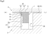
- the right side in the plane of paper of FIG. 2 will be described as a sealed fluid side L
- the left side in the plane of paper will be described as an atmosphere side A.
- the fluid pressure of sealed fluid on the sealed fluid side L will be described as a higher pressure than an atmospheric pressure.
- a sliding surface includes a flat surface and a groove recessed as compared to the flat surface.
- the flat surface forming the sliding surface is, in the side views, indicated by the color of white, and the groove forming the sliding surface is indicated by dots.
- the seal ring 1 seals a portion between a rotary shaft 2 and a housing 3 of a rotary machine, the rotary shaft 2 and the housing 3 rotating relative to each other. In this manner, the seal ring 1 partitions the inside of the housing 3 into the sealed fluid side L and the atmosphere side A (see FIG. 2 ), and prevents leakage of the sealed fluid from the sealed fluid side L to the atmosphere side A.
- the rotary shaft 2 and the housing 3 are made of a metal material such as stainless steel.
- the sealed fluid is one used for the purpose of cooling and lubricating, e.g., a not-shown gear and a not-shown bearing provided in a machine chamber of the rotary machine, such as oil.
- the seal ring 1 is a component molded with resin such as PTFE, and is provided with a joint portion 1a at one spot in a circumferential direction to form a C-shape.
- the seal ring 1 is used with the seal ring 1 being attached to an annular groove 20, the annular groove 20 being provided along the outer periphery of the rotary shaft 2 and having a rectangular sectional shape.
- the rotary shaft 2 rotates clockwise as indicated by a white arrow in FIG. 3 , and the seal ring 1 rotates counterclockwise relative to the annular groove 20 of the rotary shaft 2. Note that in FIG. 2 , the section of the seal ring 1 along a radial direction is schematically illustrated.
- the seal ring 1 has a rectangular sectional shape.
- the seal ring 1 is pressed to the atmosphere side A by the fluid pressure of the sealed fluid acting on a side surface on the sealed fluid side L, and accordingly, a sliding surface S1 formed on a side surface 10 (hereinafter sometimes merely referred to as a "side surface 10") side on the atmosphere side A slidably closely contacts a sliding surface S2 on a side wall surface 21 (hereinafter sometimes merely referred to as a "side wall surface 21”) side of the annular groove 20 on the atmosphere side A.
- the seal ring 1 in response to stress in an expansion direction due to the fluid pressure of the sealed fluid acting on an inner circumferential surface, the seal ring 1 is pressed in an outer diameter direction, and accordingly, an outer circumferential surface 11 closely contacts an inner circumferential surface 31 of a shaft hole 30 of the housing 3.
- sliding surfaces S1, S2 form a substantial sliding region between the side surface 10 of the seal ring 1 and the side wall surface 21 of the annular groove 20 of the rotary shaft 2.
- a non-sliding surface S1' is formed continuously to an outer diameter side of the sliding surface S1 on the side surface 10 side
- a non-sliding surface S2' is formed continuously to an inner diameter side of the sliding surface S2 on the side wall surface 21 side (see FIG. 2 ) .
- the sliding surface S1 formed on the side surface 10 side of the seal ring 1 includes a flat surface 16, multiple supply grooves 13 extending in the radial direction from an inner-diameter-side end portion of the side surface 10, a communication groove 14 communicating with outer-diameter-side end portions of the supply grooves 13 and formed continuously in a substantially annular shape across the joint portion 1a, and multiple inclined grooves 15 communicating with an outer-diameter-side end portion of the communication groove 14 and formed inclined to the outer diameter side in the direction of rotation of the rotary shaft 2.
- the supply grooves 13 and the inclined grooves 15 are arranged at equal intervals in the circumferential direction of the sliding surface S1, except for the vicinity of the joint portion 1a.
- the flat surface 16 includes a seal portion 16a positioned on the outer diameter side of the multiple inclined grooves 15 and formed continuously in a substantially annular shape across the joint portion 1a, an inner-diameter-side lubrication portion 16b sandwiched by adjacent ones of the supply grooves 13 in the circumferential direction, and an outer-diameter-side lubrication portion 16c sandwiched by adjacent ones of the inclined grooves 15 in the circumferential direction (see FIG. 3 ).
- the supply groove 13 supplies, regardless of rotation/stop of the rotary shaft 2, the sealed fluid to a portion between the sliding surfaces S1, S2 when the sealed fluid has a higher pressure than that of atmospheric air.
- the supply groove 13 has a rectangular shape as viewed from the side.
- the supply groove 13 opens on the inner diameter side (i.e., the sealed fluid side) of the sliding surface S1, and communicates with the communication groove 14 on the outer diameter side.
- a bottom surface 13d (see FIG. 4A ) of the supply groove 13 is formed flat, and is parallel with the flat surface 16.
- the depth of the supply groove 13 is several tens to several hundreds of ⁇ m and preferably 100 to 200 ⁇ m. Note that the depth of the supply groove 13 may be deeper (e.g., up to about a depth of 1 mm) .
- the communication groove 14 is formed to extend in the circumferential direction at a position on the outer diameter side with respect to the center of the sliding surface S1 in the radial direction, has an arc shape as viewed from the side, and has a shorter dimension in the radial direction than the dimension of the supply groove 13 in the circumferential direction. Moreover, a bottom surface 14d of the communication groove 14 is formed flat, is parallel with the flat surface 16, and is formed continuously to the bottom surface 13d of the supply groove 13. The depth of the communication groove 14 is substantially the same as that of the supply groove 13 (see FIG. 4A ).
- the inclined groove 15 extends to the outer diameter side in the rotation direction of the rotary shaft 2 from the communication groove 14, i.e., extends inclined with respect to the radial direction, and has the function of generating a dynamic pressure according to rotation of the rotary shaft 2.
- the inclined groove 15 is configured such that an introduction port 15a communicating with the outer-diameter-side end portion of the communication groove 14, a planar outer inclined wall portion 15b positioned on an opposite rotation side of the rotary shaft 2 and formed perpendicularly to a bottom surface 15e, a planar inner inclined wall portion 15c positioned on a rotation side of the rotary shaft 2 and formed perpendicularly to the bottom surface 15e, and a closed portion 15d crossing the outer inclined wall portion 15b and the inner inclined wall portion 15c on the outer diameter side and formed substantially parallel with the introduction port 15a formed perpendicularly to the bottom surface 15e form a parallelogram shape as viewed from the side.
- the inclined groove 15 has the substantially same dimension in the circumferential direction as the dimension of the communication groove 14 in the radial direction, and has a longer dimension in an extension direction than the dimension in the circumferential direction. Moreover, the inclined groove 15 is arranged on the outer diameter side with respect to the center of the sliding surface S1 in the radial direction. Further, the bottom surface 15e of the inclined groove 15 is formed flat, and is parallel with the flat surface 16. The depth of the inclined groove 15 is shallower than those of the supply groove 13 and the communication groove 14.
- the outer-diameter-side lubrication portion 16c having a shorter dimension in the circumferential direction than the dimension of the inclined groove 15 in the circumferential direction is interposed between adjacent ones of the inclined grooves 15 in the circumferential direction.
- the dimensions of these portions may be the same as each other, or the outer-diameter-side lubrication portion 16c may have a longer dimension.
- the multiple inclined grooves 15 may be formed with a curvature such that the outer-diameter-side lubrication portions 16c are formed to the outer diameter side with the substantially equal width.
- FIGS. 4A, 4B , and 5 fluid film formation between the sliding surface S1 of the seal ring 1 and the sliding surface S2 of the side wall surface 21 of the annular groove 20 (hereinafter sometimes merely referred to as "between the sliding surfaces S1, S2") will be described with reference to FIGS. 4A, 4B , and 5 .
- a case where the rotary shaft 2 rotates clockwise as indicated by the white arrow in FIG. 3 i.e., a case where the seal ring 1 rotates counterclockwise relative to the annular groove 20 of the rotary shaft 2 in FIG. 3 , will be described herein by way of example.
- 4A, 4B , and 5 schematically illustrates an association between an enlarged partial side view of the seal ring 1 as viewed from the side and an A-A sectional view cut along the supply groove 13, the communication groove 14, and the inclined groove 15 of the enlarged partial side view.
- the force of slightly separating the sliding surfaces S1, S2 from each other, i.e., buoyancy, can be generated.
- the sliding surface S2 passes over the supply grooves 13, and therefore, the sealed fluid flows out of the supply grooves 13 to follow the rotation direction of the rotary shaft 2.
- the sliding surfaces S1, S2 are slightly separated from each other by the above-described buoyancy and the above-described resting pressure, a fluid film of the sealed fluid is formed between the sliding surfaces S1, S2. Moreover, the pressure-increased sealed fluid is supplied from the closed portions 15d of the inclined grooves 15 to the vicinity of the seal portion 16a, and therefore, the fluid film is reliably formed on the seal portion 16a and lubricity is enhanced. Meanwhile, the communication groove 14 communicates with an introduction port 15a side, and therefore, the sealed fluid is continuously supplied to the inclined grooves 15 without depletion of the sealed fluid. Note that the sealed fluid is continuously supplied to the communication groove 14 through the supply grooves 13 without depletion of the sealed fluid.
- the multiple inclined grooves 15 are formed at equal intervals across the circumferential direction, and therefore, the dynamic pressure is substantially uniformly generated across the outer diameter side (a closed portion 15d side of each inclined groove 15 and the seal portion 16a) of the sliding surface S1.
- stable buoyancy can be obtained across the circumferential direction.
- the sealed fluid is mainly supplied from the inclined grooves 15 to a portion between the sliding surface S2 and the seal portion 16a, but also the high-pressure sealed fluid is supplied from the inclined grooves 15 and the communication groove 14 to the outer-diameter-side lubrication portion 16c interposed between adjacent ones of the inclined grooves 15 in the circumferential direction and is supplied from the inner diameter side of the sliding surface S1 and the supply grooves 13 to the inner-diameter-side lubrication portion 16b defined by adjacent ones of the supply grooves 13 and the communication groove 14.
- the fluid film of the sealed fluid having a substantially equal thickness is formed between the sliding surfaces S1, S2.
- the high-pressure sealed fluid introduced through inner-diameter-side openings of the supply grooves 13 is drawn from the inner diameter side of the inclined grooves 15, and generates the positive pressure on the outer diameter side of the inclined grooves 15.
- the fluid film can be formed with favorable balance in the circumferential direction on the outer diameter side of the inclined grooves 15, and therefore, stable lubrication performance can be provided across a wide range of rotation speed.
- the sealed fluid is sufficiently supplied as described above, and therefore, the fluid film can be reliably formed between the sliding surfaces S1, S2 across a wide range of rotation speed.
- the lubricity of the seal ring 1 can be enhanced.
- the supply grooves 13 are equally arranged in the circumferential direction, and therefore, the high-pressure sealed fluid introduced through the openings of the supply grooves 13 is supplied to the communication groove 14 and the inclined grooves 15 with favorable balance in the circumferential direction.
- the fluid film is formed with favorable balance in the circumferential direction on the outer diameter side of the inclined grooves 15.
- one supply groove 13 communicates with the multiple inclined grooves 15, and therefore, the high-pressure sealed fluid introduced through the openings of the supply grooves 13 is supplied to the inclined grooves 15 with more favorable balance in the circumferential direction.
- the fluid film is formed with favorable balance in the circumferential direction on the outer diameter side of the inclined grooves 15.
- the multiple inclined grooves 15 communicate with each other through the communication groove 14 extending in the circumferential direction, and the communication groove 14 communicates with the supply grooves 13.
- the high-pressure sealed fluid introduced into the supply grooves 13 is supplied in the circumferential direction of the sliding surfaces S1, S2 by the communication groove 14, and therefore, the sealed fluid is supplied from the communication groove 14 to the inclined grooves 15 with favorable balance in the circumferential direction.
- all of the multiple inclined grooves 15 communicate with each other through the communication groove 14 extending in the circumferential direction, and therefore, the high-pressure sealed fluid introduced into the supply grooves 13 is supplied in the circumferential direction of the sliding surfaces S1, S2 by the communication groove 14.
- the sealed fluid is reliably supplied to all of the inclined grooves 15 with favorable balance in the circumferential direction.
- the introduction ports 15a formed on the inner diameter side of the inclined grooves 15 are provided on the outer diameter side of the sliding surfaces S1, S2, and therefore, the positive pressure can be generated on the outer diameter side with respect to the introduction ports 15a of the inclined grooves 15.
- the fluid film can be formed with favorable balance in the circumferential direction on the outermost diameter side of the sliding surfaces S1, S2.
- the seal ring 1 is in the C-shape, and therefore, seal performance can be stably maintained even when the circumferential length of the seal ring 1 changes due to thermal expansion/contraction.
- FIGS. 6 and 7 a seal ring according to a second embodiment of the present invention will be described with reference to FIGS. 6 and 7 .
- the same reference numerals are used to represent the same components as those described in the above-described embodiment, and overlapping description thereof will be omitted.
- a sliding surface S1 (see FIG. 2 ) formed at a side surface 110 of the seal ring 101 includes a flat surface 16, multiple supply grooves 13, a communication groove 14, multiple inclined grooves 15, and a dynamic pressure groove 12 provided between adjacent ones of the supply grooves 13 in a circumferential direction.
- the dynamic pressure groove 12 has the function of generating a dynamic pressure according to rotation of a rotary shaft 2.
- the dynamic pressure groove 12 includes a deep groove 120 opening on an inner diameter side (i.e., the sealed fluid side) of the seal ring 101 and provided at the center in the circumferential direction and a pair of shallow grooves 121, 122 (also referred to as a positive pressure generator and a negative pressure generator) formed continuously from both sides of the deep groove 120 in the circumferential direction and extending in the circumferential direction.
- An inner-diameter-side lubrication portion 16b in an inverted U-shape as viewed from the side is arranged between the dynamic pressure groove 12 and each of the supply grooves 13 adjacent to such a dynamic pressure groove 12 in the circumferential direction and the communication groove 14.
- the right side with respect to the deep groove 120 in the plane of paper is the shallow groove 121 (i.e., the positive pressure generator), and the left side in the plane of paper is the shallow groove 122 (the negative pressure generator).
- the deep groove 120 has a bottom surface formed flat, and the shallow grooves 121, 122 have bottom surfaces as inclined surfaces formed such that the shallow grooves 121, 122 gradually become shallower from a deep groove 120 side to terminal ends in the circumferential direction.
- the bottom surface of the deep groove 120 is formed much deeper than deepest portions of the shallow grooves 121, 122, and the depth of the deep groove 120 is several tens to several hundreds of ⁇ m and preferably 100 to 200 ⁇ m.
- a negative pressure is generated in each shallow groove 122 (hereinafter merely referred to as a "shallow groove 122") of the seal ring 101 on a side (the left side in the plane of paper of FIG. 6 ) opposite to a rotation direction of the rotary shaft 2.
- sealed fluid introduced into the deep grooves 120 is supplied to each shallow groove 121 (hereinafter merely referred to as a "shallow groove 121") of the seal ring 101 on the same side (i.e., the right side in the plane of paper of FIG. 6 ) as the rotation direction, and a positive pressure is generated in such a shallow groove 121 due to wedge action caused by the inclined surface.
- the positive pressure is generated across the entirety of the dynamic pressure grooves 12, and accordingly, the force of slightly separating the sliding surfaces S1, S2 from each other, i.e., so-called buoyancy, is obtained. That is, the positive pressure (i.e., the buoyancy) can be generated not only on an outer diameter side of the sliding surfaces S1, S2 but also on an inner diameter side by the dynamic pressure grooves 12. Thus, responsiveness of fluid film formation to rotation of the rotary shaft 2 can be enhanced.
- the force of sucking the sealed fluid present between the sliding surfaces S1, S2 around the shallow groove 122 generating the negative pressure acts on such a shallow groove 122.
- the sealed fluid is supplied to the shallow groove 122 and a surrounding inner-diameter-side lubrication portion 16b thereof from the supply groove 13 adjacent to such a shallow groove 122 in the circumferential direction.
- the shallow groove 122 as the negative pressure generator in the dynamic pressure groove 12 opens on the inner diameter side (i.e., the sealed fluid side), and the sealed fluid is also introduced from the inner diameter side of the sliding surface S1.
- the sealed fluid is easily held on the shallow groove 122.
- the dynamic pressure groove 12 arranged on the inner diameter side of the sliding surface S1 may be freely formed, and may be formed as, e.g., a T-shaped groove, a Rayleigh step, or a spiral groove.
- FIG. 8 a seal ring according to a third embodiment of the present invention will be described with reference to FIG. 8 .
- the same reference numerals are used to represent the same components as those described in the above-described embodiments, and overlapping description thereof will be omitted.
- a sliding surface S1 (see FIG. 2 ) formed at a side surface 210 of the seal ring 201 includes a flat surface 16, multiple supply grooves 13, a communication groove 14, multiple inclined grooves 15, and a dynamic pressure groove 112 provided between adjacent ones of the supply grooves 13 in a circumferential direction.
- the dynamic pressure groove 112 includes a deep groove 220 opening on an inner diameter side (i.e., the sealed fluid side) of the seal ring 201, provided at the center in the circumferential direction, and communicating with the communication groove at an outer-diameter-side end portion and a pair of shallow grooves 121, 122 formed continuously from both sides of the deep groove 220 in the circumferential direction and extending in the circumferential direction.
- An inner-diameter-side lubrication portion 16b in an L-shape as viewed from the side is arranged between the dynamic pressure groove 112 and each of the supply grooves 13 adjacent to such a dynamic pressure groove 112 and the communication groove 14.
- sealed fluid in fluid film formation between the sliding surfaces S1, S2, sealed fluid can be supplied to the communication groove 14 not only from the supply grooves 13 but also from the deep grooves 220 of the dynamic pressure grooves 112.
- a fluid film can be more reliably formed between the sliding surfaces S1, S2 across a wide range of rotation speed, and lubricity of the seal ring 201 can be enhanced.
- FIG. 9 a seal ring according to a fourth embodiment of the present invention will be described with reference to FIG. 9 .
- the same reference numerals are used to represent the same components as those described in the above-described embodiments, and overlapping description thereof will be omitted.
- a sliding surface S1 (see FIG. 2 ) formed at a side surface 310 of the seal ring 301 includes a flat surface 16, multiple supply grooves 113, and a single inclined groove 115 communicating with each supply groove 113. According to such a configuration, stable buoyancy in a circumferential direction can be, with a simple configuration, obtained at outermost diameter portions of the sliding surfaces S1, S2.
- a sliding surface S1 (see FIG. 2 ) formed at a side surface 410 of the seal ring 401 includes a flat surface 16, multiple supply grooves 213, multiple communication paths 214 each communicating with adjacent two of the supply grooves 213, and multiple inclined grooves 215 communicating with each communication path 214. According to such a configuration, stable buoyancy in a circumferential direction can be, with a simpler configuration than those of the first to third embodiments, obtained at outermost diameter portions of the sliding surfaces S1, S2.
- the configuration of the dynamic pressure groove of the second embodiment or the third embodiment may be applied to the fourth and fifth embodiments.
- the number and shape of dynamic pressure grooves provided at the sliding surface S1 of the seal ring, the number and shape of supply grooves provided at the sliding surface S1 of the seal ring, the number and shape of communication paths provided at the sliding surface S1 of the seal ring, and the number and shape of inclined grooves provided at the sliding surface S1 of the seal ring may be changed as necessary such that a desired dynamic pressure effect is obtained.
- the location and shape of the deep groove of the dynamic pressure groove to which the sealed fluid is introduced may be changed as necessary according to the assumed degree of abrasion of the sliding surface.
- the inclined groove may have a bottom surface as an inclined surface formed such that the inclined groove gradually becomes shallower from the introduction port side to the closed portion.
- the seal ring may be formed in an annular shape without the joint portion 1a, and the outer shape thereof is not limited to a circular shape as viewed from the side.
- the seal ring may be formed in a polygonal shape.
- the seal ring is not limited to the rectangular sectional shape, and for example, may have a trapezoidal sectional shape or a polygonal sectional shape.
- the seal ring may be configured such that the side surface forming the sliding surface S1 is inclined.
- grooves described in the above-described embodiments may be formed at the sliding surface S2 of the annular groove 20 of the rotary shaft 2.
- the sealed fluid may be liquid such as water or coolant or gas such as air or nitrogen.
Landscapes
- Engineering & Computer Science (AREA)
- General Engineering & Computer Science (AREA)
- Mechanical Engineering (AREA)
- Chemical & Material Sciences (AREA)
- Oil, Petroleum & Natural Gas (AREA)
- Physics & Mathematics (AREA)
- Fluid Mechanics (AREA)
- Sealing Devices (AREA)
- Mechanical Sealing (AREA)
Claims (6)
- Dichtungsring (1, 101, 201, 301, 401) zur Abdichtung eines Spaltes zwischen einer Rotationswelle (2) und einem Gehäuse (3), wobei der Dichtungsring (1, 101, 201, 301, 401) Folgendes aufweist:eine Seitenfläche auf der abgedichteten Flüssigkeitsseite (L),eine Seitenfläche (10) auf der Atmosphärenseite (A), undeine Gleitfläche (S1), die Teil der Seitenfläche (10) auf der Atmosphärenseite (A) ist,dadurch gekennzeichnet, dass der Dichtungsring (1, 101, 201, 301, 401) ferner Folgendes aufweist:schräge Nuten (15, 115, 215), die an der Gleitfläche (S1) so ausgebildet sind, dass sie in einer Umfangsrichtung angeordnet sind, wobei die schrägen Nuten (15, 115, 215) an einer Außendurchmesserseite davon geschlossen sind und so ausgestaltet sind, dass sie einen dynamischen Druck erzeugen, undZuführungsnuten (13, 113, 213), die an der Gleitfläche (S1) ausgebildet sind und die sich auf der abgedichteten Flüssigkeitsseite (L) öffnen und mit einer Innendurchmesserseite der geneigten Nuten (15, 115, 215) in Verbindung stehen.
- Dichtungsring (1, 101, 201, 301, 401) nach Anspruch 1, wobei die Zuführungsnuten (13, 113, 213) gleichmäßig in Umfangsrichtung angeordnet sind.
- Dichtungsring (1, 101, 201, 301, 401) nach Anspruch 1 oder 2, dadurch gekennzeichnet, dass
eine der Zuführungsnuten (13, 113, 213) mit mindestens zwei der schrägen Nuten (15, 115, 215) in Verbindung steht. - Dichtungsring (1, 101, 201, 301, 401) nach einem der Ansprüche 1 bis 3, der weiterhin eine Verbindungsnut (14) aufweist, durch die die schrägen Nuten (15, 115, 215) miteinander in Verbindung stehen und die sich in Umfangsrichtung erstreckt, wobei
die Verbindungsnut (14) mit den Zuführungsnuten (13, 113, 213) in Verbindung steht. - Dichtungsring (1, 101, 201, 301, 401) nach Anspruch 4, wobei
alle schrägen Nuten (15, 115, 215) über die in Umfangsrichtung verlaufende Verbindungsnut (14) miteinander in Verbindung stehen. - Dichtungsring (1, 101, 201, 301, 401) nach einem der Ansprüche 1 bis 5, wobei
jede der schräg verlaufenden Nuten (15, 115, 215) mit einer auf ihrer Innendurchmesserseite mündenden Einführöffnung (15a) versehen ist, wobei die Einführöffnung (15a) auf einer Außendurchmesserseite der Gleitfläche (S1) angeordnet ist.
Applications Claiming Priority (2)
| Application Number | Priority Date | Filing Date | Title |
|---|---|---|---|
| JP2018095698 | 2018-05-17 | ||
| PCT/JP2019/019500 WO2019221228A1 (ja) | 2018-05-17 | 2019-05-16 | シールリング |
Publications (4)
| Publication Number | Publication Date |
|---|---|
| EP3816487A1 EP3816487A1 (de) | 2021-05-05 |
| EP3816487A4 EP3816487A4 (de) | 2022-02-23 |
| EP3816487B1 true EP3816487B1 (de) | 2024-08-21 |
| EP3816487C0 EP3816487C0 (de) | 2024-08-21 |
Family
ID=68540337
Family Applications (1)
| Application Number | Title | Priority Date | Filing Date |
|---|---|---|---|
| EP19803232.8A Active EP3816487B1 (de) | 2018-05-17 | 2019-05-16 | Dichtungsring |
Country Status (5)
| Country | Link |
|---|---|
| US (1) | US11525512B2 (de) |
| EP (1) | EP3816487B1 (de) |
| JP (1) | JP7214722B2 (de) |
| CN (1) | CN112105851B (de) |
| WO (1) | WO2019221228A1 (de) |
Families Citing this family (34)
| Publication number | Priority date | Publication date | Assignee | Title |
|---|---|---|---|---|
| US11391376B2 (en) | 2016-08-15 | 2022-07-19 | Eagle Industry Co., Ltd. | Sliding component |
| US11603934B2 (en) | 2018-01-12 | 2023-03-14 | Eagle Industry Co., Ltd. | Sliding component |
| CN111656065B (zh) * | 2018-02-01 | 2022-10-04 | 伊格尔工业股份有限公司 | 滑动部件 |
| JP7210565B2 (ja) * | 2018-05-17 | 2023-01-23 | イーグル工業株式会社 | シールリング |
| EP3816489B1 (de) | 2018-05-17 | 2024-10-09 | Eagle Industry Co., Ltd. | Dichtungsring |
| CN112424514B (zh) | 2018-08-24 | 2023-04-28 | 伊格尔工业股份有限公司 | 滑动部件 |
| JP7334017B2 (ja) | 2018-10-01 | 2023-08-28 | イーグル工業株式会社 | 摺動部材 |
| KR102661123B1 (ko) | 2018-10-24 | 2024-04-29 | 이구루코교 가부시기가이샤 | 슬라이딩 부재 |
| WO2020110922A1 (ja) | 2018-11-30 | 2020-06-04 | イーグル工業株式会社 | 摺動部品 |
| US11821521B2 (en) | 2018-12-21 | 2023-11-21 | Eagle Industry Co., Ltd. | Sliding component |
| KR102576181B1 (ko) | 2019-02-04 | 2023-09-07 | 이구루코교 가부시기가이샤 | 슬라이딩 부품 |
| KR102627904B1 (ko) | 2019-02-04 | 2024-01-23 | 이구루코교 가부시기가이샤 | 슬라이딩 부품 |
| EP3922876B1 (de) | 2019-02-04 | 2024-12-04 | Eagle Industry Co., Ltd. | Gleitkomponente |
| EP4400736B1 (de) | 2019-02-04 | 2025-09-17 | Eagle Industry Co., Ltd. | Gleitkomponente und verfahren zur herstellung eines gleitelements |
| JP7307102B2 (ja) | 2019-02-04 | 2023-07-11 | イーグル工業株式会社 | 摺動部品 |
| EP3922871B1 (de) | 2019-02-04 | 2024-01-24 | Eagle Industry Co., Ltd. | Gleitkomponente |
| CN117432709A (zh) | 2019-02-14 | 2024-01-23 | 伊格尔工业股份有限公司 | 滑动部件 |
| CN113454353B (zh) | 2019-02-21 | 2023-05-02 | 伊格尔工业股份有限公司 | 滑动部件 |
| KR102651943B1 (ko) | 2019-03-22 | 2024-03-29 | 이구루코교 가부시기가이샤 | 슬라이딩 부품 |
| EP4006368B1 (de) * | 2019-07-26 | 2024-10-09 | Eagle Industry Co., Ltd. | Gleitkomponente |
| US12110968B2 (en) * | 2020-03-09 | 2024-10-08 | Eagle Industry Co., Ltd. | Sliding component |
| EP4130523A4 (de) | 2020-03-31 | 2024-04-17 | Eagle Industry Co., Ltd. | Schiebekomponente |
| US12449040B2 (en) | 2020-05-11 | 2025-10-21 | Eagle Industry Co., Ltd. | Sliding component |
| JP7497132B2 (ja) | 2020-07-06 | 2024-06-10 | イーグル工業株式会社 | 摺動部品 |
| CN115768989B (zh) | 2020-07-06 | 2024-11-26 | 伊格尔工业股份有限公司 | 滑动部件 |
| EP4177501A4 (de) | 2020-07-06 | 2024-08-14 | Eagle Industry Co., Ltd. | Schiebekomponente |
| WO2022009767A1 (ja) | 2020-07-06 | 2022-01-13 | イーグル工業株式会社 | 摺動部品 |
| CN115917171A (zh) | 2020-07-06 | 2023-04-04 | 伊格尔工业股份有限公司 | 滑动部件 |
| CN115917192A (zh) | 2020-07-06 | 2023-04-04 | 伊格尔工业股份有限公司 | 滑动部件 |
| JP7608033B2 (ja) | 2021-03-12 | 2025-01-06 | イーグル工業株式会社 | 摺動部品 |
| CN117980636A (zh) | 2021-09-28 | 2024-05-03 | 伊格尔工业股份有限公司 | 滑动部件 |
| KR20250008107A (ko) * | 2022-05-19 | 2025-01-14 | 이구루코교 가부시기가이샤 | 슬라이딩 부품 |
| CN115614109B (zh) * | 2022-10-13 | 2024-05-17 | 中国航发四川燃气涡轮研究院 | 一种耐负压圆周石墨密封结构 |
| EP4667791A1 (de) * | 2023-02-13 | 2025-12-24 | Eagle Industry Co., Ltd. | Mechanische dichtung |
Family Cites Families (48)
| Publication number | Priority date | Publication date | Assignee | Title |
|---|---|---|---|---|
| EP0218322A1 (de) | 1985-08-12 | 1987-04-15 | Ford Motor Company Limited | Radaufhängung mit einer quer eingebauten Blattfeder |
| CH677266A5 (de) | 1986-10-28 | 1991-04-30 | Pacific Wietz Gmbh & Co Kg | |
| JP2554542B2 (ja) | 1989-07-06 | 1996-11-13 | 株式会社 藤井合金製作所 | ガスコックの製造方法 |
| JPH0388062A (ja) | 1989-08-31 | 1991-04-12 | Toshiba Corp | 文書作成装置 |
| JPH0388062U (de) * | 1989-12-26 | 1991-09-09 | ||
| JPH07117165B2 (ja) | 1991-02-27 | 1995-12-18 | 日本ピラー工業株式会社 | 非接触形シール装置 |
| DE4209484A1 (de) | 1991-06-12 | 1993-10-21 | Heinz Konrad Prof Dr I Mueller | Gleitringdichtung mit Rückförderwirkung |
| US5174584A (en) | 1991-07-15 | 1992-12-29 | General Electric Company | Fluid bearing face seal for gas turbine engines |
| JPH0561566A (ja) | 1991-09-03 | 1993-03-12 | Canon Inc | ラツプトツプ型情報処理装置 |
| US5447316A (en) | 1992-02-06 | 1995-09-05 | Eagle Industry Co., Ltd. | Gas seal |
| JP3885972B2 (ja) | 1993-09-01 | 2007-02-28 | デュラメタリック コーポレーション | 角度をつけた円環状の溝を有する面封止装置 |
| US5498007A (en) | 1994-02-01 | 1996-03-12 | Durametallic Corporation | Double gas barrier seal |
| JPH0828709A (ja) | 1994-07-22 | 1996-02-02 | Nok Corp | シールリング |
| JPH09210211A (ja) | 1996-02-01 | 1997-08-12 | Riken Corp | シールリング |
| JPH10281299A (ja) | 1997-04-11 | 1998-10-23 | Mitsubishi Heavy Ind Ltd | メカニカルシール装置 |
| US6189896B1 (en) | 1999-04-08 | 2001-02-20 | Caterpillar Inc. | Controlled leakage rotating seal ring with elements for receiving and holding a lubricant on a face thereof |
| JP4719414B2 (ja) | 2003-12-22 | 2011-07-06 | イーグル工業株式会社 | 摺動部品 |
| US7377518B2 (en) | 2004-05-28 | 2008-05-27 | John Crane Inc. | Mechanical seal ring assembly with hydrodynamic pumping mechanism |
| JP4820471B2 (ja) | 2004-11-09 | 2011-11-24 | イーグル工業株式会社 | メカニカルシール装置 |
| JP2008275052A (ja) * | 2007-04-27 | 2008-11-13 | Nok Corp | シールリング |
| JP2009250378A (ja) | 2008-04-08 | 2009-10-29 | Eagle Ind Co Ltd | 液体用のメカニカルシール装置 |
| CN201448439U (zh) | 2009-06-30 | 2010-05-05 | 张家港市金鹰密封件厂 | 机械密封装置的摩擦环 |
| JPWO2011105513A1 (ja) | 2010-02-26 | 2013-06-20 | Nok株式会社 | シールリング |
| EP2549155B1 (de) * | 2010-03-15 | 2016-08-10 | Eagle Industry Co., Ltd. | Gleitelement |
| JP5122607B2 (ja) | 2010-06-17 | 2013-01-16 | キヤノンマシナリー株式会社 | 平面摺動機構 |
| WO2012046749A1 (ja) | 2010-10-06 | 2012-04-12 | イーグル工業株式会社 | 摺動部品 |
| CN102619742B (zh) | 2012-03-07 | 2016-04-20 | 大连华阳密封股份有限公司 | 用于双向旋转内压式泵用干气密封装置 |
| US9772037B2 (en) * | 2012-08-04 | 2017-09-26 | Eagle Industry Co., Ltd. | Sliding component |
| JP2014055645A (ja) | 2012-09-13 | 2014-03-27 | Nok Corp | シールリング |
| CN104334938B (zh) | 2012-09-29 | 2017-07-07 | 伊格尔工业股份有限公司 | 滑动部件 |
| JP6219367B2 (ja) | 2013-03-14 | 2017-10-25 | イーグルブルグマンジャパン株式会社 | メカニカルシール装置 |
| JP6476121B2 (ja) | 2013-09-27 | 2019-02-27 | 株式会社リケン | シールリング |
| US9695940B2 (en) | 2013-12-18 | 2017-07-04 | Kaydon Ring & Seal, Inc. | Bidirectional lift-off circumferential shaft seal segment and a shaft seal including a plurality of the segments |
| CN105917151A (zh) | 2014-01-24 | 2016-08-31 | Nok株式会社 | 密封圈 |
| CN106574725B (zh) * | 2014-09-04 | 2019-04-16 | 伊格尔工业股份有限公司 | 机械密封件 |
| EP3239543B1 (de) | 2014-12-22 | 2022-10-05 | Eagle Industry Co., Ltd. | Gleitlager und pumpe |
| EP3273115B1 (de) | 2015-03-16 | 2019-11-06 | Nok Corporation | Dichtungsring |
| JP6428916B2 (ja) | 2015-03-16 | 2018-11-28 | Nok株式会社 | シールリング |
| EP3273117B1 (de) | 2015-03-16 | 2019-10-23 | Nok Corporation | Dichtungsring |
| CN107407424B (zh) | 2015-04-15 | 2019-11-22 | 伊格尔工业股份有限公司 | 滑动部件 |
| JP6678169B2 (ja) | 2015-05-19 | 2020-04-08 | イーグル工業株式会社 | 摺動部品 |
| JP6186413B2 (ja) | 2015-10-15 | 2017-08-23 | 株式会社リケン | シールリング |
| JP6798776B2 (ja) | 2015-10-16 | 2020-12-09 | 株式会社リケン | シールリング |
| AU2017341527A1 (en) | 2016-10-14 | 2019-05-02 | Eagle Industry Co., Ltd. | Sliding component |
| JP6910371B2 (ja) | 2016-11-14 | 2021-07-28 | イーグル工業株式会社 | しゅう動部品 |
| JP7043414B2 (ja) | 2016-11-16 | 2022-03-29 | イーグル工業株式会社 | しゅう動部品 |
| WO2019059341A1 (ja) | 2017-09-21 | 2019-03-28 | Nok株式会社 | シールリング |
| KR102391390B1 (ko) | 2018-02-08 | 2022-04-27 | 엔오케이 가부시키가이샤 | 밀봉 링 |
-
2019
- 2019-05-16 US US17/047,631 patent/US11525512B2/en active Active
- 2019-05-16 CN CN201980027746.2A patent/CN112105851B/zh active Active
- 2019-05-16 JP JP2020519916A patent/JP7214722B2/ja active Active
- 2019-05-16 WO PCT/JP2019/019500 patent/WO2019221228A1/ja not_active Ceased
- 2019-05-16 EP EP19803232.8A patent/EP3816487B1/de active Active
Also Published As
| Publication number | Publication date |
|---|---|
| US20210116030A1 (en) | 2021-04-22 |
| EP3816487A4 (de) | 2022-02-23 |
| CN112105851A (zh) | 2020-12-18 |
| JPWO2019221228A1 (ja) | 2021-05-27 |
| EP3816487A1 (de) | 2021-05-05 |
| WO2019221228A1 (ja) | 2019-11-21 |
| US11525512B2 (en) | 2022-12-13 |
| CN112105851B (zh) | 2023-02-28 |
| EP3816487C0 (de) | 2024-08-21 |
| JP7214722B2 (ja) | 2023-01-30 |
Similar Documents
| Publication | Publication Date | Title |
|---|---|---|
| EP3816487B1 (de) | Dichtungsring | |
| EP3816489B1 (de) | Dichtungsring | |
| EP3816488B1 (de) | Dichtungsring | |
| EP3816490B1 (de) | Dichtungsring | |
| EP3795868B1 (de) | Dichtungsring | |
| US11767916B2 (en) | Sliding components | |
| KR102407098B1 (ko) | 슬라이딩 부품 | |
| EP3315832B1 (de) | Gleitkomponente | |
| JPWO2019013233A1 (ja) | 摺動部材 | |
| WO2016148043A1 (ja) | シールリング | |
| US20240360872A1 (en) | Sliding components |
Legal Events
| Date | Code | Title | Description |
|---|---|---|---|
| STAA | Information on the status of an ep patent application or granted ep patent |
Free format text: STATUS: THE INTERNATIONAL PUBLICATION HAS BEEN MADE |
|
| PUAI | Public reference made under article 153(3) epc to a published international application that has entered the european phase |
Free format text: ORIGINAL CODE: 0009012 |
|
| STAA | Information on the status of an ep patent application or granted ep patent |
Free format text: STATUS: REQUEST FOR EXAMINATION WAS MADE |
|
| 17P | Request for examination filed |
Effective date: 20201201 |
|
| AK | Designated contracting states |
Kind code of ref document: A1 Designated state(s): AL AT BE BG CH CY CZ DE DK EE ES FI FR GB GR HR HU IE IS IT LI LT LU LV MC MK MT NL NO PL PT RO RS SE SI SK SM TR |
|
| DAV | Request for validation of the european patent (deleted) | ||
| DAX | Request for extension of the european patent (deleted) | ||
| A4 | Supplementary search report drawn up and despatched |
Effective date: 20220126 |
|
| RIC1 | Information provided on ipc code assigned before grant |
Ipc: F16J 15/34 20060101ALI20220120BHEP Ipc: F16J 15/44 20060101ALI20220120BHEP Ipc: F16J 15/3272 20160101ALI20220120BHEP Ipc: F16J 15/18 20060101AFI20220120BHEP |
|
| STAA | Information on the status of an ep patent application or granted ep patent |
Free format text: STATUS: EXAMINATION IS IN PROGRESS |
|
| 17Q | First examination report despatched |
Effective date: 20231107 |
|
| GRAP | Despatch of communication of intention to grant a patent |
Free format text: ORIGINAL CODE: EPIDOSNIGR1 |
|
| STAA | Information on the status of an ep patent application or granted ep patent |
Free format text: STATUS: GRANT OF PATENT IS INTENDED |
|
| INTG | Intention to grant announced |
Effective date: 20240425 |
|
| GRAS | Grant fee paid |
Free format text: ORIGINAL CODE: EPIDOSNIGR3 |
|
| GRAA | (expected) grant |
Free format text: ORIGINAL CODE: 0009210 |
|
| STAA | Information on the status of an ep patent application or granted ep patent |
Free format text: STATUS: THE PATENT HAS BEEN GRANTED |
|
| AK | Designated contracting states |
Kind code of ref document: B1 Designated state(s): AL AT BE BG CH CY CZ DE DK EE ES FI FR GB GR HR HU IE IS IT LI LT LU LV MC MK MT NL NO PL PT RO RS SE SI SK SM TR |
|
| REG | Reference to a national code |
Ref country code: GB Ref legal event code: FG4D |
|
| REG | Reference to a national code |
Ref country code: CH Ref legal event code: EP |
|
| REG | Reference to a national code |
Ref country code: DE Ref legal event code: R096 Ref document number: 602019057501 Country of ref document: DE |
|
| REG | Reference to a national code |
Ref country code: IE Ref legal event code: FG4D |
|
| U01 | Request for unitary effect filed |
Effective date: 20240821 |
|
| U07 | Unitary effect registered |
Designated state(s): AT BE BG DE DK EE FI FR IT LT LU LV MT NL PT SE SI Effective date: 20240827 |
|
| PG25 | Lapsed in a contracting state [announced via postgrant information from national office to epo] |
Ref country code: NO Free format text: LAPSE BECAUSE OF FAILURE TO SUBMIT A TRANSLATION OF THE DESCRIPTION OR TO PAY THE FEE WITHIN THE PRESCRIBED TIME-LIMIT Effective date: 20241121 |
|
| PG25 | Lapsed in a contracting state [announced via postgrant information from national office to epo] |
Ref country code: PL Free format text: LAPSE BECAUSE OF FAILURE TO SUBMIT A TRANSLATION OF THE DESCRIPTION OR TO PAY THE FEE WITHIN THE PRESCRIBED TIME-LIMIT Effective date: 20240821 Ref country code: GR Free format text: LAPSE BECAUSE OF FAILURE TO SUBMIT A TRANSLATION OF THE DESCRIPTION OR TO PAY THE FEE WITHIN THE PRESCRIBED TIME-LIMIT Effective date: 20241122 |
|
| PG25 | Lapsed in a contracting state [announced via postgrant information from national office to epo] |
Ref country code: IS Free format text: LAPSE BECAUSE OF FAILURE TO SUBMIT A TRANSLATION OF THE DESCRIPTION OR TO PAY THE FEE WITHIN THE PRESCRIBED TIME-LIMIT Effective date: 20241221 |
|
| PG25 | Lapsed in a contracting state [announced via postgrant information from national office to epo] |
Ref country code: HR Free format text: LAPSE BECAUSE OF FAILURE TO SUBMIT A TRANSLATION OF THE DESCRIPTION OR TO PAY THE FEE WITHIN THE PRESCRIBED TIME-LIMIT Effective date: 20240821 |
|
| PG25 | Lapsed in a contracting state [announced via postgrant information from national office to epo] |
Ref country code: ES Free format text: LAPSE BECAUSE OF FAILURE TO SUBMIT A TRANSLATION OF THE DESCRIPTION OR TO PAY THE FEE WITHIN THE PRESCRIBED TIME-LIMIT Effective date: 20240821 Ref country code: RS Free format text: LAPSE BECAUSE OF FAILURE TO SUBMIT A TRANSLATION OF THE DESCRIPTION OR TO PAY THE FEE WITHIN THE PRESCRIBED TIME-LIMIT Effective date: 20241121 |
|
| PG25 | Lapsed in a contracting state [announced via postgrant information from national office to epo] |
Ref country code: RS Free format text: LAPSE BECAUSE OF FAILURE TO SUBMIT A TRANSLATION OF THE DESCRIPTION OR TO PAY THE FEE WITHIN THE PRESCRIBED TIME-LIMIT Effective date: 20241121 Ref country code: PL Free format text: LAPSE BECAUSE OF FAILURE TO SUBMIT A TRANSLATION OF THE DESCRIPTION OR TO PAY THE FEE WITHIN THE PRESCRIBED TIME-LIMIT Effective date: 20240821 Ref country code: NO Free format text: LAPSE BECAUSE OF FAILURE TO SUBMIT A TRANSLATION OF THE DESCRIPTION OR TO PAY THE FEE WITHIN THE PRESCRIBED TIME-LIMIT Effective date: 20241121 Ref country code: IS Free format text: LAPSE BECAUSE OF FAILURE TO SUBMIT A TRANSLATION OF THE DESCRIPTION OR TO PAY THE FEE WITHIN THE PRESCRIBED TIME-LIMIT Effective date: 20241221 Ref country code: HR Free format text: LAPSE BECAUSE OF FAILURE TO SUBMIT A TRANSLATION OF THE DESCRIPTION OR TO PAY THE FEE WITHIN THE PRESCRIBED TIME-LIMIT Effective date: 20240821 Ref country code: GR Free format text: LAPSE BECAUSE OF FAILURE TO SUBMIT A TRANSLATION OF THE DESCRIPTION OR TO PAY THE FEE WITHIN THE PRESCRIBED TIME-LIMIT Effective date: 20241122 Ref country code: ES Free format text: LAPSE BECAUSE OF FAILURE TO SUBMIT A TRANSLATION OF THE DESCRIPTION OR TO PAY THE FEE WITHIN THE PRESCRIBED TIME-LIMIT Effective date: 20240821 |
|
| PG25 | Lapsed in a contracting state [announced via postgrant information from national office to epo] |
Ref country code: SM Free format text: LAPSE BECAUSE OF FAILURE TO SUBMIT A TRANSLATION OF THE DESCRIPTION OR TO PAY THE FEE WITHIN THE PRESCRIBED TIME-LIMIT Effective date: 20240821 |
|
| PG25 | Lapsed in a contracting state [announced via postgrant information from national office to epo] |
Ref country code: CZ Free format text: LAPSE BECAUSE OF FAILURE TO SUBMIT A TRANSLATION OF THE DESCRIPTION OR TO PAY THE FEE WITHIN THE PRESCRIBED TIME-LIMIT Effective date: 20240821 |
|
| PG25 | Lapsed in a contracting state [announced via postgrant information from national office to epo] |
Ref country code: SK Free format text: LAPSE BECAUSE OF FAILURE TO SUBMIT A TRANSLATION OF THE DESCRIPTION OR TO PAY THE FEE WITHIN THE PRESCRIBED TIME-LIMIT Effective date: 20240821 |
|
| PGFP | Annual fee paid to national office [announced via postgrant information from national office to epo] |
Ref country code: GB Payment date: 20250327 Year of fee payment: 7 |
|
| U20 | Renewal fee for the european patent with unitary effect paid |
Year of fee payment: 7 Effective date: 20250407 |
|
| PLBE | No opposition filed within time limit |
Free format text: ORIGINAL CODE: 0009261 |
|
| STAA | Information on the status of an ep patent application or granted ep patent |
Free format text: STATUS: NO OPPOSITION FILED WITHIN TIME LIMIT |
|
| 26N | No opposition filed |
Effective date: 20250522 |
|
| REG | Reference to a national code |
Ref country code: CH Ref legal event code: H13 Free format text: ST27 STATUS EVENT CODE: U-0-0-H10-H13 (AS PROVIDED BY THE NATIONAL OFFICE) Effective date: 20251223 |
|
| PG25 | Lapsed in a contracting state [announced via postgrant information from national office to epo] |
Ref country code: CH Free format text: LAPSE BECAUSE OF NON-PAYMENT OF DUE FEES Effective date: 20250531 |
|
| PG25 | Lapsed in a contracting state [announced via postgrant information from national office to epo] |
Ref country code: MC Free format text: LAPSE BECAUSE OF FAILURE TO SUBMIT A TRANSLATION OF THE DESCRIPTION OR TO PAY THE FEE WITHIN THE PRESCRIBED TIME-LIMIT Effective date: 20240821 |