EP3812654B1 - Vehicle lighting system - Google Patents
Vehicle lighting system Download PDFInfo
- Publication number
- EP3812654B1 EP3812654B1 EP19823152.4A EP19823152A EP3812654B1 EP 3812654 B1 EP3812654 B1 EP 3812654B1 EP 19823152 A EP19823152 A EP 19823152A EP 3812654 B1 EP3812654 B1 EP 3812654B1
- Authority
- EP
- European Patent Office
- Prior art keywords
- light
- light source
- luminescent layer
- holding member
- lighting system
- Prior art date
- Legal status (The legal status is an assumption and is not a legal conclusion. Google has not performed a legal analysis and makes no representation as to the accuracy of the status listed.)
- Active
Links
Images







Classifications
-
- F—MECHANICAL ENGINEERING; LIGHTING; HEATING; WEAPONS; BLASTING
- F21—LIGHTING
- F21S—NON-PORTABLE LIGHTING DEVICES; SYSTEMS THEREOF; VEHICLE LIGHTING DEVICES SPECIALLY ADAPTED FOR VEHICLE EXTERIORS
- F21S43/00—Signalling devices specially adapted for vehicle exteriors, e.g. brake lamps, direction indicator lights or reversing lights
- F21S43/20—Signalling devices specially adapted for vehicle exteriors, e.g. brake lamps, direction indicator lights or reversing lights characterised by refractors, transparent cover plates, light guides or filters
- F21S43/255—Filters
-
- F—MECHANICAL ENGINEERING; LIGHTING; HEATING; WEAPONS; BLASTING
- F21—LIGHTING
- F21S—NON-PORTABLE LIGHTING DEVICES; SYSTEMS THEREOF; VEHICLE LIGHTING DEVICES SPECIALLY ADAPTED FOR VEHICLE EXTERIORS
- F21S43/00—Signalling devices specially adapted for vehicle exteriors, e.g. brake lamps, direction indicator lights or reversing lights
- F21S43/20—Signalling devices specially adapted for vehicle exteriors, e.g. brake lamps, direction indicator lights or reversing lights characterised by refractors, transparent cover plates, light guides or filters
- F21S43/281—Materials thereof; Structures thereof; Properties thereof; Coatings thereof
-
- F—MECHANICAL ENGINEERING; LIGHTING; HEATING; WEAPONS; BLASTING
- F21—LIGHTING
- F21S—NON-PORTABLE LIGHTING DEVICES; SYSTEMS THEREOF; VEHICLE LIGHTING DEVICES SPECIALLY ADAPTED FOR VEHICLE EXTERIORS
- F21S43/00—Signalling devices specially adapted for vehicle exteriors, e.g. brake lamps, direction indicator lights or reversing lights
- F21S43/10—Signalling devices specially adapted for vehicle exteriors, e.g. brake lamps, direction indicator lights or reversing lights characterised by the light source
- F21S43/13—Signalling devices specially adapted for vehicle exteriors, e.g. brake lamps, direction indicator lights or reversing lights characterised by the light source characterised by the type of light source
- F21S43/14—Light emitting diodes [LED]
-
- F—MECHANICAL ENGINEERING; LIGHTING; HEATING; WEAPONS; BLASTING
- F21—LIGHTING
- F21S—NON-PORTABLE LIGHTING DEVICES; SYSTEMS THEREOF; VEHICLE LIGHTING DEVICES SPECIALLY ADAPTED FOR VEHICLE EXTERIORS
- F21S43/00—Signalling devices specially adapted for vehicle exteriors, e.g. brake lamps, direction indicator lights or reversing lights
- F21S43/10—Signalling devices specially adapted for vehicle exteriors, e.g. brake lamps, direction indicator lights or reversing lights characterised by the light source
- F21S43/13—Signalling devices specially adapted for vehicle exteriors, e.g. brake lamps, direction indicator lights or reversing lights characterised by the light source characterised by the type of light source
- F21S43/14—Light emitting diodes [LED]
- F21S43/145—Surface emitters, e.g. organic light emitting diodes [OLED]
-
- F—MECHANICAL ENGINEERING; LIGHTING; HEATING; WEAPONS; BLASTING
- F21—LIGHTING
- F21S—NON-PORTABLE LIGHTING DEVICES; SYSTEMS THEREOF; VEHICLE LIGHTING DEVICES SPECIALLY ADAPTED FOR VEHICLE EXTERIORS
- F21S43/00—Signalling devices specially adapted for vehicle exteriors, e.g. brake lamps, direction indicator lights or reversing lights
- F21S43/10—Signalling devices specially adapted for vehicle exteriors, e.g. brake lamps, direction indicator lights or reversing lights characterised by the light source
- F21S43/13—Signalling devices specially adapted for vehicle exteriors, e.g. brake lamps, direction indicator lights or reversing lights characterised by the light source characterised by the type of light source
- F21S43/16—Light sources where the light is generated by photoluminescent material spaced from a primary light generating element
-
- F—MECHANICAL ENGINEERING; LIGHTING; HEATING; WEAPONS; BLASTING
- F21—LIGHTING
- F21S—NON-PORTABLE LIGHTING DEVICES; SYSTEMS THEREOF; VEHICLE LIGHTING DEVICES SPECIALLY ADAPTED FOR VEHICLE EXTERIORS
- F21S43/00—Signalling devices specially adapted for vehicle exteriors, e.g. brake lamps, direction indicator lights or reversing lights
- F21S43/20—Signalling devices specially adapted for vehicle exteriors, e.g. brake lamps, direction indicator lights or reversing lights characterised by refractors, transparent cover plates, light guides or filters
- F21S43/235—Light guides
- F21S43/236—Light guides characterised by the shape of the light guide
- F21S43/239—Light guides characterised by the shape of the light guide plate-shaped
-
- F—MECHANICAL ENGINEERING; LIGHTING; HEATING; WEAPONS; BLASTING
- F21—LIGHTING
- F21S—NON-PORTABLE LIGHTING DEVICES; SYSTEMS THEREOF; VEHICLE LIGHTING DEVICES SPECIALLY ADAPTED FOR VEHICLE EXTERIORS
- F21S43/00—Signalling devices specially adapted for vehicle exteriors, e.g. brake lamps, direction indicator lights or reversing lights
- F21S43/20—Signalling devices specially adapted for vehicle exteriors, e.g. brake lamps, direction indicator lights or reversing lights characterised by refractors, transparent cover plates, light guides or filters
- F21S43/235—Light guides
- F21S43/242—Light guides characterised by the emission area
- F21S43/245—Light guides characterised by the emission area emitting light from one or more of its major surfaces
-
- F—MECHANICAL ENGINEERING; LIGHTING; HEATING; WEAPONS; BLASTING
- F21—LIGHTING
- F21S—NON-PORTABLE LIGHTING DEVICES; SYSTEMS THEREOF; VEHICLE LIGHTING DEVICES SPECIALLY ADAPTED FOR VEHICLE EXTERIORS
- F21S43/00—Signalling devices specially adapted for vehicle exteriors, e.g. brake lamps, direction indicator lights or reversing lights
- F21S43/20—Signalling devices specially adapted for vehicle exteriors, e.g. brake lamps, direction indicator lights or reversing lights characterised by refractors, transparent cover plates, light guides or filters
- F21S43/235—Light guides
- F21S43/247—Light guides with a single light source being coupled into the light guide
-
- F—MECHANICAL ENGINEERING; LIGHTING; HEATING; WEAPONS; BLASTING
- F21—LIGHTING
- F21S—NON-PORTABLE LIGHTING DEVICES; SYSTEMS THEREOF; VEHICLE LIGHTING DEVICES SPECIALLY ADAPTED FOR VEHICLE EXTERIORS
- F21S43/00—Signalling devices specially adapted for vehicle exteriors, e.g. brake lamps, direction indicator lights or reversing lights
- F21S43/20—Signalling devices specially adapted for vehicle exteriors, e.g. brake lamps, direction indicator lights or reversing lights characterised by refractors, transparent cover plates, light guides or filters
- F21S43/235—Light guides
- F21S43/252—Two or more successive light guides
-
- F—MECHANICAL ENGINEERING; LIGHTING; HEATING; WEAPONS; BLASTING
- F21—LIGHTING
- F21S—NON-PORTABLE LIGHTING DEVICES; SYSTEMS THEREOF; VEHICLE LIGHTING DEVICES SPECIALLY ADAPTED FOR VEHICLE EXTERIORS
- F21S43/00—Signalling devices specially adapted for vehicle exteriors, e.g. brake lamps, direction indicator lights or reversing lights
- F21S43/20—Signalling devices specially adapted for vehicle exteriors, e.g. brake lamps, direction indicator lights or reversing lights characterised by refractors, transparent cover plates, light guides or filters
- F21S43/26—Refractors, transparent cover plates, light guides or filters not provided in groups F21S43/235 - F21S43/255
-
- F—MECHANICAL ENGINEERING; LIGHTING; HEATING; WEAPONS; BLASTING
- F21—LIGHTING
- F21S—NON-PORTABLE LIGHTING DEVICES; SYSTEMS THEREOF; VEHICLE LIGHTING DEVICES SPECIALLY ADAPTED FOR VEHICLE EXTERIORS
- F21S43/00—Signalling devices specially adapted for vehicle exteriors, e.g. brake lamps, direction indicator lights or reversing lights
- F21S43/20—Signalling devices specially adapted for vehicle exteriors, e.g. brake lamps, direction indicator lights or reversing lights characterised by refractors, transparent cover plates, light guides or filters
- F21S43/2605—Refractors
-
- F—MECHANICAL ENGINEERING; LIGHTING; HEATING; WEAPONS; BLASTING
- F21—LIGHTING
- F21S—NON-PORTABLE LIGHTING DEVICES; SYSTEMS THEREOF; VEHICLE LIGHTING DEVICES SPECIALLY ADAPTED FOR VEHICLE EXTERIORS
- F21S43/00—Signalling devices specially adapted for vehicle exteriors, e.g. brake lamps, direction indicator lights or reversing lights
- F21S43/30—Signalling devices specially adapted for vehicle exteriors, e.g. brake lamps, direction indicator lights or reversing lights characterised by reflectors
-
- F—MECHANICAL ENGINEERING; LIGHTING; HEATING; WEAPONS; BLASTING
- F21—LIGHTING
- F21S—NON-PORTABLE LIGHTING DEVICES; SYSTEMS THEREOF; VEHICLE LIGHTING DEVICES SPECIALLY ADAPTED FOR VEHICLE EXTERIORS
- F21S45/00—Arrangements within vehicle lighting devices specially adapted for vehicle exteriors, for purposes other than emission or distribution of light
- F21S45/70—Prevention of harmful light leakage
-
- F—MECHANICAL ENGINEERING; LIGHTING; HEATING; WEAPONS; BLASTING
- F21—LIGHTING
- F21V—FUNCTIONAL FEATURES OR DETAILS OF LIGHTING DEVICES OR SYSTEMS THEREOF; STRUCTURAL COMBINATIONS OF LIGHTING DEVICES WITH OTHER ARTICLES, NOT OTHERWISE PROVIDED FOR
- F21V7/00—Reflectors for light sources
- F21V7/22—Reflectors for light sources characterised by materials, surface treatments or coatings, e.g. dichroic reflectors
- F21V7/24—Reflectors for light sources characterised by materials, surface treatments or coatings, e.g. dichroic reflectors characterised by the material
- F21V7/26—Reflectors for light sources characterised by materials, surface treatments or coatings, e.g. dichroic reflectors characterised by the material the material comprising photoluminescent substances
-
- F—MECHANICAL ENGINEERING; LIGHTING; HEATING; WEAPONS; BLASTING
- F21—LIGHTING
- F21V—FUNCTIONAL FEATURES OR DETAILS OF LIGHTING DEVICES OR SYSTEMS THEREOF; STRUCTURAL COMBINATIONS OF LIGHTING DEVICES WITH OTHER ARTICLES, NOT OTHERWISE PROVIDED FOR
- F21V9/00—Elements for modifying spectral properties, polarisation or intensity of the light emitted, e.g. filters
- F21V9/30—Elements containing photoluminescent material distinct from or spaced from the light source
- F21V9/38—Combination of two or more photoluminescent elements of different materials
-
- F—MECHANICAL ENGINEERING; LIGHTING; HEATING; WEAPONS; BLASTING
- F21—LIGHTING
- F21W—INDEXING SCHEME ASSOCIATED WITH SUBCLASSES F21K, F21L, F21S and F21V, RELATING TO USES OR APPLICATIONS OF LIGHTING DEVICES OR SYSTEMS
- F21W2103/00—Exterior vehicle lighting devices for signalling purposes
-
- F—MECHANICAL ENGINEERING; LIGHTING; HEATING; WEAPONS; BLASTING
- F21—LIGHTING
- F21W—INDEXING SCHEME ASSOCIATED WITH SUBCLASSES F21K, F21L, F21S and F21V, RELATING TO USES OR APPLICATIONS OF LIGHTING DEVICES OR SYSTEMS
- F21W2107/00—Use or application of lighting devices on or in particular types of vehicles
- F21W2107/10—Use or application of lighting devices on or in particular types of vehicles for land vehicles
-
- F—MECHANICAL ENGINEERING; LIGHTING; HEATING; WEAPONS; BLASTING
- F21—LIGHTING
- F21Y—INDEXING SCHEME ASSOCIATED WITH SUBCLASSES F21K, F21L, F21S and F21V, RELATING TO THE FORM OR THE KIND OF THE LIGHT SOURCES OR OF THE COLOUR OF THE LIGHT EMITTED
- F21Y2115/00—Light-generating elements of semiconductor light sources
- F21Y2115/10—Light-emitting diodes [LED]
-
- F—MECHANICAL ENGINEERING; LIGHTING; HEATING; WEAPONS; BLASTING
- F21—LIGHTING
- F21Y—INDEXING SCHEME ASSOCIATED WITH SUBCLASSES F21K, F21L, F21S and F21V, RELATING TO THE FORM OR THE KIND OF THE LIGHT SOURCES OR OF THE COLOUR OF THE LIGHT EMITTED
- F21Y2115/00—Light-generating elements of semiconductor light sources
- F21Y2115/10—Light-emitting diodes [LED]
- F21Y2115/15—Organic light-emitting diodes [OLED]
Definitions
- the present invention relates to a light source unit of a vehicle lighting system and a vehicle lighting system.
- a typical vehicle lighting system with a function of signal lighting, such as tail lights includes a light source unit.
- the light source unit includes a light source, a plate-like light guide lens to guide light from the light source, and a lens member to output light, guided by the light guide lens, toward the front of the vehicle (for example, JP 2017-92010 A ).
- the organic light-emitting diode is a structure in which an electrode, an organic layer, and another electrode are laminated on a substrate, and a current flowing between the electrodes causes electrical deterioration when electroluminescence occurs, which makes the light source less reliable.
- the manufacturing cost of an organic light-emitting diode is high. Such a light source unit is therefore desired that can provide surface emitting while securing reliability of the light source and reducing the cost.
- the present invention has been made from the above point of view, and has an object to provide a light source unit of a vehicle lighting system and a vehicle lighting system that are capable of providing surface emitting while securing reliability of the light source and reducing the cost.
- a vehicle lighting system includes a light source, a light generating unit, and a lens member.
- the light source emits excitation light.
- the light generating unit includes a luminescent layer to emit generation light by being irradiated with the excitation light and holding members that hold the luminescent layer.
- the lens member outputs the generation light from the luminescent layer toward a front, with the light source unit mounted on a vehicle.
- the luminescent layer may be made of an organic material.
- the light generating unit may include a sealer that transmits the excitation light and the generation light and seals the luminescent layer.
- the holding members may transmit the excitation light.
- the luminescent layers included in the light generating units may be in a form of a frame a dimension of which is different from one another when viewed from the front.
- the luminescent layer may emit red light, as the generation light.
- the lens member may transmit red light and absorbs light different from red light.
- the light source may be disposed under the luminescent layer with the light source unit mounted on a vehicle.
- the reflective layer may be curvedly projecting toward the back.
- the luminescent layer may emit red light, as the generation light.
- the lens member may transmit red light and absorbs light different from red light.
- a vehicle lighting system is provided that is capable of providing surface emitting while securing reliability of the light source and reducing the cost.
- various directions such as a forward-rearward direction, an up-down direction, a left-right direction
- the up-down direction is parallel to the vertical direction
- the left-right direction indicates the horizontal direction.
- a front side of the light source unit denotes a direction in which light is emitted from the light source unit of the vehicle lighting system
- a back side of the light source unit is a direction opposite to the front side.
- FIG. 1 is a side view of an example vehicle lighting system 100 according to an embodiment.
- the vehicle lighting system 100 illustrated in FIG. 1 is, for example, a signal light, such as a tail light.
- the front side of the light source unit is therefore consistent with the rearward side of the vehicle, and the back side is consistent with the forward side of the vehicle.
- the vehicle lighting system 100 includes a light source unit U1 including a light source assembly 10, a light generating unit 20, and a lens member 30, and an inner panel 40.
- the vehicle lighting system 100 further includes a lamp housing that accommodates the light source unit U1 and the inner panel 40, and a lamp lens.
- FIG. 2 is a perspective view of the example light source unit U1. As illustrated in FIG. 1 and FIG. 2 , the light source unit U1 includes the light source assembly 10 and the light generating unit 20.
- the light source part 10 includes the light source 11, the support substrate 12, and the heat sink 13.
- the light source 11 is, for example, a semiconductor light source, such as an LED, an OEL, and an OLED (organic EL).
- the light source 11 is disposed, for example, under the light generating unit 20 with a light-emitting surface 11a facing the light generating unit 20 (facing up).
- the light source 11 emits light through the light-emitting surface 11a in the form of a Lambertian luminous distribution.
- the light source 11 emits blue light, as excitation light, through the light-emitting surface 11a.
- Light emitted from the light source 11 is not limited to blue light.
- the light source 11 may emit light having a shorter wavelength (such as purple light and ultraviolet) than the wavelength of generation light generated by the later-described light generating unit 20.
- the support substrate 12 supports the light source 11.
- the support substrate 12 is supported by the heat sink 13.
- the heat sink 13 is retained by, for example, a bracket (not illustrated).
- the light generating unit 20 includes a holding member 21, a luminescent layer 22, and a sealer 23.
- the holding member 21 is supported separately from the light source assembly 10 by, for example, a bracket (not illustrated). Separation of the holding member 21 from the light source part 10 allows more flexible arrangement of the light source part 10 and the light generating unit 20. The light source part 10 and the light generating unit 20 are therefore allowed to be flexibly arranged depending on the overall design.
- the holding member 21 is capable of transmitting excitation light emitted from the light source 11.
- the holding member 21 can transmit excitation light and illuminate the entire surface of the later-described luminescent layer 22 by guiding the excitation light throughout the inside of the holding member 21.
- the holding member 21 of this embodiment is, for example, a rectangular plate and transmits generation light emitted from the later-described luminescent layer 22.
- the holding member 21 may be a rigid substrate formed of glass or a similar material or may be a flexible substrate formed of acrylic resin, thermoplastic resin, or a similar material.
- the holding member 21 has flat portions 21a and 21b at the front and back surfaces thereof.
- the flat portion 21a is disposed facing the rearward side (the front side), and the flat portion 21b is disposed facing the forward side (the back side).
- the holding member 21 has four side surfaces that connect the flat portion 21a and the flat portion 21b with each other.
- a side surface, of the four side surfaces, facing down includes a light-receiving surface 21f that faces the light-emitting surface 11a. Excitation light enters the holding member 21 through the light-receiving surface 21f, and is guided throughout the inside of the holding member 21.
- the luminescent layer 22 is held by the holding member 21.
- the luminescent layer 22 emits generation light by being irradiated with excitation light from the light source 11. More specifically, the luminescent layers 22 are held by the respective flat portions 21a and 21b of the holding member 21.
- the luminescent layer 22 formed on the flat portion 21a and the luminescent layer 22 on the flat portion 21b will be referred to as, respectively, a luminescent layer 22a and a luminescent layer 22b, as needed.
- the luminescent layer 22 is formed as a thin film, for example, by performing thin-film preparation processing on each of the flat portions 21a and 21b.
- the luminescent layer 22 is transparent unless otherwise irradiated with excitation light.
- the luminescent layer 22 is made of an organic material or the like that is composed of a host material, such as polyvinylcarbazole, approximately 5% doped with a red phosphorescent material, such as acetylacetone. In this composition, the luminescent layer 22 emits red light as the generation light.
- the host material and the dopant are not limited to the above materials.
- the luminescent layer 22 may use an inorganic material, such as yttrium aluminum garnet (YAG).
- the luminescent layer 22a and the luminescent layer 22b are identical to each other in size and shape, and are consistently aligned, for example, when viewed from the front.
- FIG. 3 is a drawing of the example light generating unit 20 when viewed from the front.
- the luminescent layers 22a and 22b in this embodiment are rectangular, the shape is not limited thereto.
- the luminescent layers 22a and 22b may have a shape corresponding to the shape of the tail light when viewed from the front.
- the luminescent layers 22a and 22b formed in the above size and shape and aligned as described above, form a luminescent region 22R when viewed from the front.
- the luminescent region 22R is defined by, for example, the outer peripheries of the luminescent layers 22a and 22b.
- Red light generated in the luminescent layer 22a is partially emitted toward the front side.
- Red light generated in the luminescent layer 22b partially passes through the holding member 21 and the luminescent layer 22a and is emitted toward the front.
- the red light from the luminescent layers 22a and 22b goes out from the luminescent region 22R toward the front, to provide surface emitting.
- the sealer 23 transmits excitation light and red light.
- the sealer 23 seals the luminescent layer 22.
- the sealer 23 may be, as with the holding member 21, a rigid substrate formed of glass, epoxy resin, or a similar material, or may be a flexible substrate formed of acrylic resin, thermoplastic resin, or a similar material.
- the lens member 30 is disposed in front of the light generating unit 20.
- the lens member 30 has the light-receiving surface 31 and the light-output surface 32.
- the light-receiving surface 31 receives red light, which is generation light emitted from the light generating unit 20.
- the light-output surface 32 outputs light incident on the light-receiving surface 31, toward the front.
- the lens member 30 transmits red light and absorbs light different from the red light.
- the lens member 30 therefore absorbs elements of excitation light contained in outside light.
- the inner panel 40 retains the lens member 30.
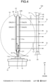
- FIG. 4 is a drawing that illustrates example operation of the vehicle lighting system 100.
- excitation light Lb is emitted from the light-emitting surface 11a in the pattern of Lambertian radiation, and a part of the excitation light Lb directly illuminates the luminescent layers 22a and 22b.
- Another part of the excitation light Lb enters the holding member 21 through the light-receiving surface 21f, and illuminates the luminescent layers 22a and 22b by being guided through the holding member 21.
- the luminescent layer 22a Upon irradiation with the excitation light Lb, the luminescent layer 22a is excited to generate red light L1. A part of the red light L1 generated at the luminescent layer 22a passes through a sealer 23a and proceeds toward the rearward side (the front side). Upon irradiation with the excitation light Lb, the luminescent layer 22b is excited to generate red light L2. A part of the red light L2 generated at the luminescent layer 22b passes through the holding member 21, the luminescent layer 22a, and the sealer 23a, and proceeds toward the rearward side (the front side). The red lights L1 and L2 generated at the luminescent layers 22a and 22b are output toward the front from the luminescent region 22R and provide surface emitting. The red lights L1 and L2 enter the light-receiving surface 31 of the lens member 30, pass through the light-output surface 32 of the lens member 30 toward the front side, and radiate, for example, in the illumination pattern of the tail light.
- the luminescent layers 22a and 22b are made of an organic material, and are transparent unless otherwise irradiated with the excitation light Lb.
- This structure therefore allows the viewer to see as if there were no luminescent layers 22a or 22b inside the lens member 30. Since the lens member 30 transmits red light and absorbs light different from red light, an element Lx of excitation light contained, for example, in outside light is absorbed by the lens member 30. This structure can prevent the luminescent layer 22 from emitting light while the light source 11 is off.
- the light source unit U1 includes the light source 11 to emit excitation light, the light generating unit 20 including the luminescent layer 22 to generate red light, or generation light, upon irradiation with the excitation light and the holding member 21 holding the luminescent layer 22, and further includes the lens member 30 to output the generation light emitted from the luminescent layer 22 toward the front, with the light source unit U1 mounted on the vehicle.
- the luminescent layer 22 generates red light, as generation light, upon irradiation with excitation light from the light source 11.
- This configuration reduces electrical deterioration which may occur in an organic light-emitting diode.
- Such a vehicle lighting system 100 that can provide surface emitting while securing reliability of the light source 11 is therefore obtained at a lower cost.
- the light source 11 is disposed separately from the holding member 21, which allows flexible arrangement of the light source assembly 10 and the light generating unit 20.
- the light source assembly 10 and the light generating unit 20 can therefore be flexibly arranged depending on the overall design.
- the luminescent layer 22 is formed of an organic material. This is effective in providing surface emitting, and allows the luminescent layer to be kept transparent unless otherwise irradiated with excitation light.
- the light generating unit 20 may include the sealer 23 that transmits excitation light and red light and seals the luminescent layer 22. Use of the sealer 23 can reduce deterioration of the luminescent layer 22 and increase the service life thereof.
- the holding member 21 is in the form of a plate having the flat portions 21a and 21b at the front and back surfaces thereof.
- the luminescent layer 22 is formed on at least one of the flat portions 21a and 21b, at the front and back surfaces of the holding member 21.
- the light generating unit 20 has the flat portion 21a having the luminescent layer 22 and disposed on the front side. This structure allows red light generated in the luminescent layer 22 to be efficiently emitted toward the front.
- the holding member 21 is capable of transmitting red light.
- the luminescent layer 22 is formed on each of the flat portions 21a and 21b at the front and back surfaces of the holding member 21. Such effective formation of the luminescent layer 22 is advantageous in obtaining a larger amount of light.
- the holding member 21 has side surfaces that connect the flat portions 21a and 21b at the front and back surfaces with each other.
- the light source 11 has the light-emitting surface 11a to emit excitation light facing one of the side surfaces. This structure allows the excitation light to enter the holding member 21 through the side surface and to illuminate the luminescent layer 22 by being guided throughout the inside of the holding member 21. This structure allows the excitation light to further efficiently illuminate the luminescent layer 22.
- the luminescent layer 22 emits red light, which is generation light. Surface emitting using red light is therefore easily obtained for use of tail lights or similar devices.
- the lens member 30 transmits red light and absorbs light different from red light.
- the lens member 30 thus can absorb elements of excitation light contained in outside light. This structure can prevent the luminescent layer 22 from emitting light while the light source 11 is off.
- the vehicle lighting system 100 includes the above light source unit U1.
- the configuration of the light source unit U1 enables surface emitting while securing reliability of the light source 11, and also enables a reduction in the cost of the light source unit U1. Stable surface emitting at a lower cost is therefore achieved with the vehicle lighting system 100.
- FIG. 5 is a side view of an example light source unit U2 according to a modification.
- the light source unit U2 includes the light source assembly 10, a light generating unit 120, and a lens member (not illustrated).
- the light source assembly 10 and the lens member have the same configurations as those described in the above embodiment.
- a holding member 121 of the light generating unit 120 has a size (thickness) in the forward-rearward direction larger than that of the holding member 21 of the embodiment. This structure allows excitation light from the light source 11 to easily enter the holding member 121. A larger amount of excitation light is therefore guided by the holding member 121 and illuminates the luminescent layers 22 (22a and 22b) .
- One of the side surfaces of the holding member 121 has a light-receiving surface 121f, and another side surface different from the side surface has a light diffusing portion 121s.
- the light diffusing portion 121s diffuses excitation light entering the holding member 121, within the holding member 121.
- Examples of the light diffusing portion 121s include a prism that causes internal reflection of the excitation light in the holding member 121. The internal reflection allows the excitation light to uniformly illuminate the entire surface of the luminescent layer 22 (22a and 22b), and red light thus can be efficiently generated in the luminescent layer 22.
- FIG. 6 is an exploded perspective view of an example light source unit U3 according to a modification.
- the light source unit U3 includes the light source assembly 10, a light generating unit 220, and a lens member (not illustrated).
- the light source assembly 10 and the lens member have the same configurations as those of the above light source unit U1.
- a holding member 221 of the light generating unit 220 is in the shape of a rectangular box made of glass or a similar material.
- the holding member 221 accommodates therein a luminescent layer 222.
- the holding member 221 is capable of transmitting excitation light emitted from the light source 11 and red light generated in the luminescent layer 222.
- the luminescent layer 222 is prepared, for example, by dissolving a host material such as polyvinylcarbazole and a red phosphorescent material such as acetylacetone in a solvent such as dichloroethane.
- the luminescent layer 222 may be formed of other materials, without being limited to the above materials.
- the luminescent layer 222 is a solid having dimensions in the up-down direction, the left-right direction, and the forward-rearward direction. For example, when viewed from the up, the center of the luminescent layer 222 in the forward-rearward direction and the left-right direction is consistent with the center of the light-emitting surface 11a of the light source 11 in the forward-rearward direction and the left-right direction. This arrangement allows excitation light emitted from the light source 11 in the pattern of Lambertian radiation to efficiently illuminate the luminescent layer 222.
- a plate-like sealer 223 is mounted on a top surface 221a of the holding member 221.
- the sealer 223 is attached to the top surface 221a of the holding member 221 with, for example, epoxy resin.
- the luminescent layer 222 is sealed inside the holding member 221 by the sealer 223.
- FIG. 7 is a side view of an example light source unit U4 according to a modification.
- the light source unit U4 includes the light source assembly 10, a light generating unit 320, and a lens member (not illustrated).
- the light source assembly 10 and the lens member have the same configurations as those of the above light source unit U1.
- the light generating unit 320 includes a plurality of light generating units 20, described in the embodiment, stacked in the forward-rearward direction (the front-back direction). Although three light generating units 20 are used in the example of FIG. 7 , the number of units is not limited thereto. Two, four, or more light generating units 20 may be used.
- a plurality of light generating units 20 are arranged in the forward-rearward direction (the front-back direction). This configuration allows excitation light to efficiently illuminate the luminescent layers 22 (22a and 22b) and thus allows the luminescent layers 22 to efficiently generate red light.
- FIG. 8 is an exploded perspective view of an example light source unit U5 according to a modification.
- FIG. 8 illustrates a light generating unit 420 separated in parts.
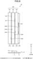
- FIG. 9 is a side view of the example light source unit U5.
- the light source unit U5 illustrated in FIG. 8 and FIG. 9 includes the light source assembly 10, the light generating unit 420, and a lens member (not illustrated).
- the light source assembly 10 and the lens member have the same configurations as those of the above light source unit U1.
- the light generating unit 420 includes a first light generating unit 421, a second light generating unit 422, and a third light generating unit 423 that are stacked in the forward-rearward direction (the front-back direction).
- the first light generating unit 421 includes a holding member 424 and a luminescent layer 425.
- the second light generating unit 422 includes a holding member 426 and a luminescent layer 427.
- the third light generating unit 423 includes a holding member 428 and a luminescent layer 429.
- the holding members 424, 426, and 428 have the same configurations as the configuration of the holding member 21 described in the above embodiment.
- the luminescent layer 425 is a thin film formed on a flat portion 424a of the holding member 424.
- the luminescent layer 427 is a thin film formed on a flat portion 426a of the holding member 426.
- the luminescent layer 429 is a thin film formed on a flat portion 428a of the holding member 428.
- the holding members 424, 426, and 428 are attached to one another with, for example, epoxy resin. More specifically, the flat portion 424a of the holding member 424 and a flat portion 426b of the holding member 426 are attached to each other, and the flat portion 426a of the holding member 426 and a flat portion 428b of the holding member 428 are attached to each other.
- the luminescent layer 425, held between the holding member 424 and the holding member 426, and the luminescent layer 427, held between the holding member 426 and the holding member 428, are sealed with epoxy resin.
- the luminescent layer 429 formed on the flat portion 428a of the holding member 428 is sealed by a sealer 430.
- the sealer 430 may have the same structure as that of the sealer 23 of the above embodiment.
- FIG. 10 is a drawing of an example light source unit U5 when viewed from the front.
- the luminescent layer 425 is in the form of a rectangular frame when viewed from the front.
- the luminescent layer 427 is in the form of a rectangular frame the dimensions of which are smaller than those of the luminescent layer 425 when viewed from the front.
- the luminescent layer 427 is arranged inside the luminescent layer 425.
- the luminescent layer 429 is in the form of a rectangular frame the dimensions of which are smaller than those of the luminescent layer 427 when viewed from the front.
- the luminescent layer 429 is arranged inside the luminescent layer 427.
- the frame-shaped luminescent layers 425, 427, and 429 have dimensions different from one another, and are located in respective different regions.
- the luminescent layers 425, 427, and 429 are not necessarily in the shape of a rectangular frame when viewed from the front, and may be in another shape.
- Red light emitted outside from these luminescent layers 425, 427, and 429 provides the viewer with a sense of depth in the illumination design.
- the luminescent layer 425 forming an outer luminescent region 425R is disposed in the most backward
- the luminescent layer 427 forming a middle luminescent region 427R is disposed in the middle in the forward-rearward direction (the front-back direction)
- the luminescent layer 429 forming an inner luminescent region 429R is disposed in the most frontward.
- the viewer sees the red light from the outer luminescent region 425R shining at the back, and the red light from the middle luminescent region 427R shining in the middle, and the red light from the inner luminescent region 429R shining at the front.
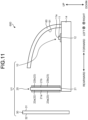
- FIG. 11 is a drawing of an example vehicle lighting system 600 according to a modification.
- the vehicle lighting system 600 includes the light source unit U1 including the light source assembly 10, the light generating unit 20, the lens member 30, and a reflector 60.
- the light source assembly 10, the light generating unit 20, and the lens member 30 have the same configurations as those described in the above embodiment.
- the light source unit U1 may be replaced by any of the above light source units U2 to U5.
- the light source assembly 10 and the light generating unit 20 are disposed on a heat sink 14, and the reflector 60 is disposed between the light source assembly 10 and the light generating unit 20.
- the reflector 60 has a reflective surface 61 that reflects excitation light from the light source 11 toward the light generating unit 20. Use of the reflector 60 allows the luminescent layer 22 to be efficiently illuminated.
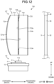
- FIG. 12 is a side view of an example vehicle lighting system 700 according to another embodiment.
- the vehicle lighting system 700 illustrated in FIG. 12 is, for example, a signal lamp, such as a tail light.
- the rearward side of the vehicle indicated in this embodiment is therefore a front side of the light source, and the forward side of the vehicle is a back side of the light source.
- the vehicle lighting system 700 includes a light source unit U7 including the light source assembly 10 and a light generating unit 720 and the lens member 30, and the inner panel 40.
- the vehicle lighting system 700 further includes a lamp housing that accommodates the light source unit U7 and the inner panel 40 and a lamp lens.
- the light source assembly 10 includes the light source 11, the support substrate 12, and the heat sink 13.
- the light source 11 is, for example, a semiconductor light source, such as an LED, an OEL, and an OLED (organic EL).
- the light source 11 is disposed, for example, under the light generating unit 720 with the light-emitting surface 11a facing the light generating unit 720 (facing up).
- the light source 11 emits light through the light-emitting surface 11a in the form of a Lambertian luminous distribution.
- the light source 11 emits blue light, as excitation light, through the light-emitting surface 11a.
- Light emitted from the light source 11 is not limited to blue light.
- the light source 11 may emit light having a shorter wavelength (such as purple light and ultraviolet) than the wavelength of generation light generated by the later-described light generating unit 720.
- the support substrate 12 supports the light source 11.
- the support substrate 12 is supported by the heat sink 13.
- the heat sink 13 is retained by, for example, a bracket (not illustrated).
- the light generating unit 720 includes holding members 721 and 722, a luminescent layer 723, a reflective layer 724, and a semi-transmissive reflective layer 725.
- the holding members 721 and 722 are supported separately from the light source assembly 10 by brackets or similar members (not illustrated). Separation of the holding members 721 and 722 from the light source assembly 10 allows more flexible arrangement of the light source assembly 10 and the light generating unit 720. The light source assembly 10 and the light generating unit 720 are therefore allowed to be flexibly arranged depending on the overall design.
- the holding members 721 and 722 are capable of transmitting excitation light emitted from the light source 11.
- the holding members 721 and 722 transmit the excitation light and illuminate the entire surface of the later-described luminescent layer 723 by guiding the excitation light throughout the inside of the holding members 721 and 722.
- the holding members 721 and 722 of this embodiment are, for example, in the form of a plate, and capable of transmitting generation light generated in the later-described luminescent layer 723.
- the holding members 721 and 722 may be rigid substrates formed of glass or a similar material or may be flexible substrates formed of acrylic resin, thermoplastic resin, or a similar material.
- the holding member 721 has a curved portion 721a and a flat portion 721b.
- the curved portion 721a is disposed facing the forward side (the back side).
- the curved portion 721a is curvedly projecting toward the forward side (the back side).
- the curved portion 721a may have the degree of projection increasing from the edges in the up-down direction and the left-right direction toward the center.
- the shape of the curved portion 721a is not limited thereto.
- the curved portion 721a may have the degree of projection increasing from the edges in either the up-down direction or the left-right direction, toward the center.
- the flat portion 721b is disposed facing the rearward side (the front side).
- the holding member 721 has four side surfaces that connect the curved portion 721a and the flat portion 721b with each other.
- a side surface, of the four side surfaces, facing down has a light-receiving surface 721f that faces the light-emitting surface 11a.
- the holding member 721 receives excitation light from the light-receiving surface 721f and guides the light throughout the inside of the holding member 721.
- the holding member 722 is disposed on the front side of the holding member 721.
- the holding member 722 has flat portions 722a and 722b.
- the flat portion 722a is disposed facing the forward side (the back side).
- the flat portion 722b is disposed facing the rearward side (the front side).
- the holding member 722 has four side surfaces that connect the flat portion 722a and the flat portion 722b with each other.
- a side surface, of the four side surfaces, facing down has a light-receiving surface 722f that faces the light-emitting surface 11a.
- the holding member 722 receives excitation light from the light-receiving surface 722f and guides the light throughout the inside of the holding member 722.
- the luminescent layer 723 Upon irradiation with the excitation light from the light source 11, the luminescent layer 723 is excited to generate generation light.
- the luminescent layer 723 is transparent unless otherwise irradiated with the excitation light.
- the luminescent layer 723 is held between the flat portion 721b of the holding member 721 and the flat portion 722a of the holding member 722.
- the luminescent layer 723 is formed as a thin film by performing thin-film preparation processing on the flat portion 721b or the flat portion 722a. Red light generated in the luminescent layer 723 is partially emitted toward the forward side and partially emitted toward the rearward side.
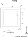
- FIG. 13 is a front view of the example light source unit U7.
- the luminescent layer 723 of this embodiment is in the form of a rectangular frame arranged along the outer peripheries of the holding members 721 and 722.
- the luminescent layer 723 has an aperture 723a in the middle thereof.
- the shape of the luminescent layer 723 is not limited thereto.
- the luminescent layer 723 is made of an organic material or the like, composed of a host material, such as polyvinylcarbazole, approximately 5% doped with a red phosphorescent material, such as acetylacetone, for example. In this composition, the luminescent layer 723 emits red light as generation light.
- the host material and the dopant are not limited to the above materials.
- the luminescent layer 723 may use an inorganic material, such as yttrium aluminum garnet (YAG).
- the reflective layer 724 is disposed on the forward side of the luminescent layer 723.
- the reflective layer 724 reflects generation light generated in the luminescent layer 723 toward the rearward side (the front side).
- the reflective layer 724 is a thin film formed of metal or a similar material and stretched along the curved portion 721a of the holding member 721.
- the reflective layer 724 is therefore curvedly projecting toward the forward side (the back side) along the curved portion 721a. More specifically, the reflective layer 724 has the degree of projection increasing from the ends in the up-down direction and the left-right direction, toward the center.
- the reflective layer 724 is similarly has the degree of projection increasing from the ends in either the up-down direction or the left-right direction toward the center.
- the semi-transmissive reflective layer 725 is disposed on the front side of the luminescent layer 723. More specifically, the semi-transmissive reflective layer 725 is located opposite to the reflective layer 724 with the luminescent layer 723 disposed therebetween. The semi-transmissive reflective layer 725 partially transmits generation light and partially reflects the generation light toward the forward side (the back side).
- the semi-transmissive reflective layer 725 is a thin film formed of metal or a similar material and stretched on the flat portion 722b of the holding member 722. The semi-transmissive reflective layer 725 is therefore flat.
- a sealer 726 is disposed between the peripheral edge of the flat portion 721b of the holding member 721 and the peripheral edge of the flat portion 722a of the holding member 722, and seals the luminescent layer 723.
- the sealer 726 may be, as with the holding members 721 and 722, a rigid substrate formed of glass, epoxy resin, or a similar material, or may be a flexible substrate formed of acrylic resin, thermoplastic resin, or a similar material.
- the sealer 726 may be provided to fill the aperture 723a of the luminescent layer 723.
- the holding member 721 and the holding member 722 may be partially accommodated in the aperture 723a of the luminescent layer 723.
- the lens member 30 is disposed in front of the light generating unit 720.
- the lens member 30 emits red light, which is generation light passing through the semi-transmissive reflective layer 725 of the light generating unit 720, toward the rearward side (the front side).
- the lens member 30 has the light-receiving surface 31 and the light-output surface 32.
- the light-receiving surface 31 receives red light passing through the semi-transmissive reflective layer 725.
- the light-output surface 32 outputs light incident on the light-receiving surface 31, toward the front side.
- the lens member 30 transmits red light and absorbs light different from the red light.
- the lens member 30 therefore absorbs elements of excitation light contained in outside light.
- the inner panel 40 retains the lens member 30.
- FIG. 14 is a drawing that illustrates example operation of the vehicle lighting system 700.
- a part of excitation light Lb emitted from the light-emitting surface 11a in the pattern of Lambertian radiation directly illuminates the luminescent layer 723.
- Another part of the excitation light Lb enters the holding members 721 and 722 through the light-receiving surfaces 721f and 722f, and illuminates the luminescent layer 723 by being guided through the holding members 721 and 722.
- the luminescent layer 723 Upon irradiation with the excitation light Lb, the luminescent layer 723 is excited to generate red light L71.
- Red light L71 generated in the luminescent layer 723 is partially emitted toward the rearward side and reaches the semi-transmissive reflective layer 725 after passing the holding member 722.
- Red light L72 as a part of the red light L71 passes through the semi-transmissive reflective layer 725 and is output toward the rearward side.
- Red light L73 as another part of the red light L71 is reflected by the semi-transmissive reflective layer 725 toward the forward side.
- the red light L73 reflected toward the forward side reaches the reflective layer 724 through the aperture 723a and is reflected toward the rearward side by the reflective layer 724.
- the red light L73 reflected by the reflective layer 724 passes through the aperture 723a and again reaches the semi-transmissive reflective layer 725. Since the reflective layer 724 of this embodiment is curvedly projecting toward the forward side, the red light L73 reflected by the reflective layer 724 reaches an inner area of the semi-transmissive reflective layer 725 than the area the red light L71 reaches. Red light L74 as a part of the red light L73 passes through the semi-transmissive reflective layer 725 and is output toward the rearward side. Red light L75 as another part of the red light L73 is reflected toward the forward side by the semi-transmissive reflective layer 725.
- the red light L75 reaches the reflective layer 724 through the aperture 723a and is reflected by the reflective layer 724 toward the rearward side.
- the red light L75 reflected by the reflective layer 724 reaches an inner area of the semi-transmissive reflective layer 725 than the area the red light L73 reaches.
- Red light L76 as a part of the red light L75 passes through the semi-transmissive reflective layer 725 and is output toward the rearward side. Another part of the red light L75 is reflected by the semi-transmissive reflective layer 725 toward the forward side.
- red light emitted from the luminescent layer 723 toward the rearward is multiply reflected between the reflective layer 724 and the semi-transmissive reflective layer 725, and is partially output toward the rearward side through the semi-transmissive reflective layer 725.
- Red light L77 as a part of the red light generated in the luminescent layer 723 is emitted toward the forward side and reaches the reflective layer 724 after passing the holding member 721.
- the red light L77 is then reflected toward the rearward side by the reflective layer 724, and reaches the semi-transmissive reflective layer 725 through the aperture 723a.
- Red light L78 as a part of the red light L77 passes through the semi-transmissive reflective layer 725 and is output toward the rearward side.
- Red light L79 as another part of the red light L77 is reflected toward the forward side by the semi-transmissive reflective layer 725.
- the red light L79 reflected toward the forward side reaches the reflective layer 724 through the aperture 723a and is reflected by the reflective layer 724 toward the rearward side.
- the red light L79 reflected by the reflective layer 724 passes through the aperture 723a and reaches an inner area of the semi-transmissive reflective layer 725 than the area the red light L77 reaches.
- Red light L80 as a part of the red light L79 passes through the semi-transmissive reflective layer 725 and is output toward the rearward side.
- Red light L81 as another part of the red light L79 is reflected toward the forward side by the semi-transmissive reflective layer 725.
- the red light L81 reaches the reflective layer 724 through the aperture 723a and is reflected toward the rearward side by the reflective layer 724.
- the red light L81 reflected by the reflective layer 724 passes through the aperture 723a and reaches an inner area of the semi-transmissive reflective layer 725 than the area the red light L79 reaches.
- Red light L82 as a part of the red light L81 passes through the semi-transmissive reflective layer 725 and is output toward the rearward side. Another part of the red light L81 is reflected toward the forward side by the semi-transmissive reflective layer 725. In this manner, similarly, red light output from the luminescent layer 723 toward the forward side is multiply reflected between the reflective layer 724 and the semi-transmissive reflective layer 725, and is partially output toward the rearward side through the semi-transmissive reflective layer 725.
- the red light L71 and red lights L72 to L76, derived from the red light L71, output toward the rearward side are illustrated in the lower part of the luminescent layer 723.
- the red light L77 and red lights L78 to L82, derived from the red light L77, output toward the forward side are illustrated in the upper part of the luminescent layer 723.
- FIG. 15 is a drawing of the example light source unit U7 when viewed from the front.
- the red lights L72 and L78 passing through the semi-transmissive reflective layer 725 form a rectangular frame-shaped luminescent region R2.
- the red lights L74 and L80 passing through the semi-transmissive reflective layer 725 form a rectangular frame-shaped luminescent region R4 inside the above luminescent region R2.
- the red lights L76 and L82 passing through the semi-transmissive reflective layer 725 form a rectangular frame-shaped luminescent region R6 inside the above luminescent region R4.
- the red lights L72 and L78 to be output from the luminescent region R2 undergo a small number of multiple reflections and thus have a short optical path, compared to the red lights to be output from other luminescent regions R4 and R6.
- the red lights L74 and L80 to be output from the luminescent region R4 have longer optical paths than those of the red lights L72 and L78 from the luminescent region R2, and have shorter optical paths than those of the red lights L76 and L82 from the luminescent region R6.
- the red lights L76 and L82 to be output from the luminescent region R6 have longer optical paths than those of the red lights from other luminescent regions R2 and R4.
- This structure allows the viewer to see as if red light from the outer luminescent region R2, of the three different luminescent regions R2, R4, and R6, was shining at the front, and the red light from the middle luminescent region R4 shining in the middle, and the red light from the inner luminescent region R6 shining at the back.
- the light source unit U7 includes: the light source assembly 10 that emits the excitation light Lb; the light generating unit 720 that includes the luminescent layer 723 configured to emit red light, which is generation light, by being irradiated with the excitation light Lb, the reflective layer 724 disposed on a back side of the luminescent layer 723 and configured to reflect red light toward the rearward side, the semi-transmissive reflective layer 725 disposed at a location that is on the front side of the luminescent layer 723 and is opposite to the reflective layer 724 with the luminescent layer 723 interposed therebetween and configured to transmit a part of the red light and to reflect another part of the red light toward the forward side, and the holding members 721 and 722 holding the luminescent layer 723, the reflective layer 724, and the semi-transmissive reflective layer 725; and the lens member 30 that is disposed on the front side of the light generating unit 720 and outputs the red light, which is the generation light, passing through the semi-
- the luminescent layer 723 is configured to emit red light, as generation light, by being irradiated with excitation light from the light source 11.
- This configuration reduces electrical deterioration which may occur in an organic light-emitting diode.
- the light source unit U7 capable of surface emitting while securing reliability of the light source 11 is therefore obtained at a low cost.
- Red light generated in the luminescent layer 723 is multiply reflected between the reflective layer 724 and the semi-transmissive reflective layer 725. A part of the red light passes through the semi-transmissive reflective layer 725 and is output from the lens member 30.
- the lens member 30 outputs red lights the optical paths of which are different in length depending on the number of multiple reflections. This configuration can provide the viewer with a sense of depth in the illumination design.
- the light source unit U7 has the luminescent layer 723 formed of an organic material. This composition is effective in creating surface emitting, and allows the luminescent layer to be kept transparent unless otherwise irradiated with excitation light.
- the luminescent layer 723 of the light source unit U7 is in the form of a frame when viewed from the rearward (from the front). This shape allows red light reflected by the semi-transmissive reflective layer 725 to pass through the aperture of the frame and to easily reach the reflective layer 724. Red light reflected by the reflective layer 724 similarly passes through the aperture of the frame and easily reaches the semi-transmissive reflective layer 725. This structure therefore achieves effective use of the red light.
- the light source unit U7 has the light source assembly 10 disposed under the luminescent layer 723 with the light source unit U7 mounted on the vehicle. This arrangement enables efficient irradiation of the luminescent layer 723 with the excitation light Lb.
- the light source unit U7 has the reflective layer 724 curvedly projecting toward the forward side. This structure allows the red light to be inwardly reflected. Since the luminescent layer 723 is exemplarily in the shape of a frame as described in this embodiment, the light source unit U7 is recognized by a viewer, viewing the light source unit U7 from the rearward side, as if a plurality of frame-shaped luminescent regions R2, R4, and R6 were located at respective different depths (in the forward-rearward direction) from the outside toward the inside.
- each of the holding members 721 and 722 has side surfaces that connect the flat portions at the front and the back with each other.
- the light source assembly 10 may have the light-emitting surface 11a to emit the excitation light Lb facing one of the side surfaces.
- This structure allows the excitation light to enter the holding members 721 and 722 through the side surfaces thereof, and to illuminate the luminescent layer 723 by being guided throughout the inside of the holding members 721 and 722. This structure therefore achieves efficient irradiation of the luminescent layer 723 with the excitation light.
- the luminescent layer 723 emits red light, as generation light. Surface emitting using red light is therefore easily obtained for use of tail lights or similar devices.
- the lens member 30 transmits red light and absorbs light different from the red light.
- the lens member 30 thus can absorb elements of excitation light contained in outside light. This structure can prevent the luminescent layer 723 from emitting light while the light source 11 is off.
- the vehicle lighting system 700 includes the above light source unit U7. Since the vehicle lighting system 700 includes the light source unit U7 capable of providing surface emitting while securing reliability of the light source 11 and reducing the cost, the vehicle lighting system 700 achieves low-cost and stable surface emitting. Since the vehicle lighting system 700 includes the light source unit U7 capable of providing a viewer with a sense of depth in the illumination design, the vehicle lighting system 700 has enhanced visibility.
- the above embodiment describes the luminescent layer 723 as a frame-shaped structure when viewed from the front.
- the luminescent layer 723 may be rectangular, polygonal, circular, elliptical, or in a similar shape.
- the above embodiment describes a structure in which the luminescent layer 723 has the aperture 723a in the middle thereof when viewed from the front.
- another structure may also be effective if there is a portion that allows transmission of light during multiple reflection between the reflective layer 724 and the semi-transmissive reflective layer 725.
- the luminescent layer 723 when viewed from the front, may be located in a certain area of the holding members 721 and 722, such as the center portion, the upper half portion, the lower half portion, the left half portion, and the right half portion.
- the reflective layer 724 exemplarily projects toward the back side from the outer periphery to the center of the holding member 721.
- the structure is not limited thereto.
- the reflective layer 724 may project toward the back side from an end to the other end of the holding member 721 in at least one of the up-down direction and the left-right direction.
- FIG. 16 is a drawing of an example vehicle lighting system 800 according to a modification.
- the vehicle lighting system 800 includes a light source unit U8 including light source assemblies 10A and 10B, a light generating unit 820, and a lens member 830, and an inner panel (not illustrated).
- the light source assembly 10A is a light source that emits white light La.
- the light source assembly 10B is a light source that emits, for example, ultraviolet as the excitation light Lb.
- the light generating unit 820 includes a holding member 821, a light reflective film 822, a luminescent layer 823, and a sealer 824.
- the holding member 821 is, for example, in the form of a plate.
- the holding member 821 may be made of, for example, a thermoplastic material such as polycarbonate, glass, and acrylic resin.
- the holding member 821 may be a rigid substrate or a flexible substrate.
- the holding member 821 may be an optically non-transmissive member.
- the light reflective film 822 is formed on the surface of the holding member 821 and reflects light emitted from the light sources 10A and 10B.
- the light reflective film 822 is made of a metallic material, such as aluminum, silver, and an alloy of these materials.
- the luminescent layer 823 is formed on the light reflective film 822.
- the luminescent layer 823 is excited by being irradiated with the excitation light Lb from the light source assembly 10B and generates generation light.
- the luminescent layer 823 transmits the white light La emitted from the light source assembly 10A.
- the luminescent layer 823 is made using, for example, 4,4'-bis(carbazoyl)biphenyl (CBP) as a host material, and, for example, Btp2Ir(acac) bis(2-(2'-benzo[4,5-a]thienyl) pyridinato-N, C3')iridium(acetylacetonate) as a guest material.
- CBP 4,4'-bis(carbazoyl)biphenyl
- Btp2Ir(acac) bis(2-(2'-benzo[4,5-a]thienyl) pyridinato-N, C3')iridium(acetylacetonate) as a guest material.
- the luminescent layer 823 made as above emits red light L90 as the generation light.
- the host material and the dopant are not limited to the above materials.
- the luminescent layer 823 may use an inorganic material, such as yt
- the sealer 824 transmits the excitation light Lb and the red light L90 and seals the luminescent layer 823.
- the sealer 824 may be made of a resin material, such as silicone resin, or an inorganic material such as SiO 2 .
- the white light La emitted from the light source assembly 10A passes through the sealer 824 and the luminescent layer 823 and reaches the light reflective film 822 and is reflected by the light reflective film 822.
- the reflected white light La passes the luminescent layer 823 and the sealer 824 and the lens member 830, and goes out. In this manner, substantially all the white light La emitted from the light source assembly 10A goes out without being absorbed.
- the excitation light Lb emitted from the light source assembly 10B passes the sealer 824 and reaches the luminescent layer 823 and is absorbed by the luminescent layer 823.
- the luminescent layer 823 generates the red light L90 by absorbing the excitation light Lb.
- a part of the generated red light L90 immediately passes the sealer 824 and reaches the lens member 830.
- Another part of the generated red light L90 proceeds toward the light reflective film 822 and is reflected by the light reflective film 822.
- the reflected red light L90 passes the luminescent layer 823 and the sealer 824 and reaches the lens member 830.
- the red light L90 reaches the lens 830 and goes out through the lens member 830.
- the above vehicle lighting system 800 can be used, for example, as a back light if the light source assembly 10A is configured to emit the white light La.
- the vehicle lighting system 800 can be used as a part of rear lighting system or accessory lights if the light source assembly 10B is configured to emit ultraviolet Lb.
- the luminescent layers 22, 222, 322, 425, 427, 429, 723, and 823 may be formed on a transparent sheet, such as a polyethylene terephthalate (PET) sheet.
- PET polyethylene terephthalate
- the excitation light Lb from the light source may be configured to directly illuminate the luminescent layer.
- the luminescent layers 22, 222, 322, 425, 427, 429, 723, and 823 may be provided to an optical member, such as an inner lens, that controls light from the light source.
- the luminescent layer is irradiated with the excitation light Lb, the distribution of which is controlled by the optical member.
Landscapes
- Engineering & Computer Science (AREA)
- General Engineering & Computer Science (AREA)
- Physics & Mathematics (AREA)
- Microelectronics & Electronic Packaging (AREA)
- Optics & Photonics (AREA)
- Spectroscopy & Molecular Physics (AREA)
- Non-Portable Lighting Devices Or Systems Thereof (AREA)
- Securing Globes, Refractors, Reflectors Or The Like (AREA)
- Planar Illumination Modules (AREA)
Applications Claiming Priority (3)
| Application Number | Priority Date | Filing Date | Title |
|---|---|---|---|
| JP2018118182 | 2018-06-21 | ||
| JP2018118212 | 2018-06-21 | ||
| PCT/JP2019/024710 WO2019245030A1 (ja) | 2018-06-21 | 2019-06-21 | 車両用灯具の光源ユニット及び車両用灯具 |
Publications (3)
| Publication Number | Publication Date |
|---|---|
| EP3812654A1 EP3812654A1 (en) | 2021-04-28 |
| EP3812654A4 EP3812654A4 (en) | 2022-01-26 |
| EP3812654B1 true EP3812654B1 (en) | 2024-04-10 |
Family
ID=68983664
Family Applications (1)
| Application Number | Title | Priority Date | Filing Date |
|---|---|---|---|
| EP19823152.4A Active EP3812654B1 (en) | 2018-06-21 | 2019-06-21 | Vehicle lighting system |
Country Status (5)
| Country | Link |
|---|---|
| US (2) | US11215335B2 (https=) |
| EP (1) | EP3812654B1 (https=) |
| JP (1) | JP7359142B2 (https=) |
| CN (2) | CN112334703B (https=) |
| WO (1) | WO2019245030A1 (https=) |
Families Citing this family (16)
| Publication number | Priority date | Publication date | Assignee | Title |
|---|---|---|---|---|
| JP7298316B2 (ja) | 2019-06-07 | 2023-06-27 | セイコーエプソン株式会社 | 電子時計の制御方法および電子時計 |
| JP2021113775A (ja) * | 2020-01-21 | 2021-08-05 | セイコーエプソン株式会社 | 時計 |
| JP7352832B2 (ja) | 2020-01-21 | 2023-09-29 | セイコーエプソン株式会社 | 電子時計 |
| JP7562977B2 (ja) | 2020-03-31 | 2024-10-08 | 市光工業株式会社 | 車両用灯具 |
| JP7652049B2 (ja) * | 2020-11-16 | 2025-03-27 | 市光工業株式会社 | 車両用灯具 |
| US12281774B2 (en) | 2020-11-16 | 2025-04-22 | Ichikoh Industries, Ltd. | Vehicle lamp having excitation light source, light conversion unit, and red lens |
| JP7666294B2 (ja) | 2020-11-16 | 2025-04-22 | 市光工業株式会社 | 車両用灯具 |
| WO2022102786A1 (ja) | 2020-11-16 | 2022-05-19 | 市光工業株式会社 | 車両用灯具 |
| CN116472424A (zh) * | 2020-11-16 | 2023-07-21 | 市光工业株式会社 | 车辆用灯具 |
| US12109941B1 (en) * | 2021-08-10 | 2024-10-08 | Apple Inc. | Windows with photoluminescent lighting |
| JP7658269B2 (ja) * | 2021-12-28 | 2025-04-08 | 市光工業株式会社 | 車両用灯具の光源ユニット及び車両用灯具 |
| JP7658268B2 (ja) * | 2021-12-28 | 2025-04-08 | 市光工業株式会社 | 車両用灯具の光源ユニット及び車両用灯具 |
| JP7658270B2 (ja) | 2021-12-28 | 2025-04-08 | 市光工業株式会社 | 車両用灯具 |
| WO2023127789A1 (ja) * | 2021-12-28 | 2023-07-06 | 市光工業株式会社 | 車両用灯具の光源ユニット及び車両用灯具 |
| JP7464078B2 (ja) | 2022-05-31 | 2024-04-09 | 市光工業株式会社 | 車両用灯具 |
| CN120231979A (zh) * | 2023-12-29 | 2025-07-01 | 赛万特科技有限责任公司 | 灯具部件和灯具装置 |
Family Cites Families (45)
| Publication number | Priority date | Publication date | Assignee | Title |
|---|---|---|---|---|
| US5931566A (en) | 1995-10-12 | 1999-08-03 | Valeo Sylvania L.L.C. | Colored and decorative lighting |
| JP2000326785A (ja) | 1999-05-19 | 2000-11-28 | Ichikoh Ind Ltd | 車両用照明装置 |
| JP2002100216A (ja) * | 2000-09-22 | 2002-04-05 | Ichikoh Ind Ltd | 車両用灯具 |
| US6908220B2 (en) | 2001-07-16 | 2005-06-21 | Toyoda Gosei Co., Ltd. | Vehicle lamp |
| WO2006019980A2 (en) * | 2004-07-16 | 2006-02-23 | Federal-Mogul Corporation | Vehicular lighting fixture with non-directional dispersion of light |
| JP2006058394A (ja) * | 2004-08-17 | 2006-03-02 | Sharp Corp | 表示装置 |
| JP2006073202A (ja) * | 2004-08-31 | 2006-03-16 | Nichia Chem Ind Ltd | 発光装置 |
| US8681071B2 (en) * | 2005-07-20 | 2014-03-25 | Daniel Deutsch | Lighted multiple panel display |
| KR101271226B1 (ko) | 2006-02-16 | 2013-06-03 | 삼성디스플레이 주식회사 | 백라이트 유닛 및 이를 포함하는 액정 표시 장치 |
| JP5431636B2 (ja) * | 2006-07-14 | 2014-03-05 | 株式会社小糸製作所 | 車両用標識灯 |
| JP4797944B2 (ja) | 2006-11-15 | 2011-10-19 | ソニー株式会社 | 光源装置及び表示装置 |
| JP4678364B2 (ja) | 2006-12-05 | 2011-04-27 | スタンレー電気株式会社 | 光源装置及び車両前照灯 |
| JP2008163809A (ja) | 2006-12-27 | 2008-07-17 | Railway Technical Res Inst | エンジン |
| JP5066462B2 (ja) * | 2008-02-29 | 2012-11-07 | スタンレー電気株式会社 | 車両用灯具 |
| US8405116B2 (en) * | 2009-03-18 | 2013-03-26 | Semiconductor Energy Laboratory Co., Ltd. | Lighting device |
| EP2412038B1 (en) * | 2009-03-19 | 2019-01-02 | Philips Lighting Holding B.V. | Illumination device with remote luminescent material |
| JP2011187285A (ja) | 2010-03-08 | 2011-09-22 | Toshiba Corp | 発光装置 |
| JP2012099362A (ja) * | 2010-11-02 | 2012-05-24 | Toshiba Corp | 発光装置 |
| JP2012243701A (ja) * | 2011-05-24 | 2012-12-10 | Stanley Electric Co Ltd | 光源装置および照明装置 |
| DE102011081919A1 (de) * | 2011-08-31 | 2013-02-28 | Automotive Lighting Reutlingen Gmbh | Lichtmodul zum Aussenden von Licht und Kraftfahrzeugbeleuchtungseinrichtung mit mindestens einem solchen Lichtmodul |
| JP2013161626A (ja) | 2012-02-03 | 2013-08-19 | Harison Toshiba Lighting Corp | 帯状照明装置 |
| WO2014018169A1 (en) * | 2012-07-23 | 2014-01-30 | Research Triangle Institute | Improved reflective nanofiber lighting devices |
| JP6044239B2 (ja) * | 2012-10-01 | 2016-12-14 | セイコーエプソン株式会社 | 撮像装置および医療機器 |
| TW201416623A (zh) * | 2012-10-25 | 2014-05-01 | 隆達電子股份有限公司 | 燈具 |
| EP2929573B1 (en) * | 2012-12-05 | 2018-06-13 | Philips Lighting Holding B.V. | A lighting unit and a luminaire |
| JP6045470B2 (ja) * | 2013-03-04 | 2016-12-14 | 信越化学工業株式会社 | 赤色ランプ及び車両用灯火装置 |
| DE102013205836A1 (de) * | 2013-04-03 | 2014-10-09 | Osram Opto Semiconductors Gmbh | Fahrzeugleuchte |
| JP6430719B2 (ja) * | 2013-09-02 | 2018-11-28 | 株式会社小糸製作所 | 車両用灯具 |
| JP2015050148A (ja) * | 2013-09-04 | 2015-03-16 | 株式会社小糸製作所 | 車両用灯具 |
| JP2015088483A (ja) * | 2013-09-26 | 2015-05-07 | 信越化学工業株式会社 | 赤色ランプ及び車両用灯火装置 |
| DE102014203245A1 (de) * | 2014-02-24 | 2015-08-27 | Automotive Lighting Reutlingen Gmbh | Beleuchtungseinrichtung eines Kraftfahrzeugs |
| CN103994387B (zh) * | 2014-05-29 | 2017-01-04 | 长城汽车股份有限公司 | 车灯和具有它的汽车 |
| US10151441B2 (en) * | 2014-10-08 | 2018-12-11 | Koito Manufacturing Co., Ltd. | Light emitting device and vehicle lamp |
| CN107407834B (zh) | 2015-03-16 | 2021-02-19 | 夏普株式会社 | 照明装置、显示装置以及电视接收装置 |
| KR102325585B1 (ko) * | 2015-05-28 | 2021-11-12 | 엘지이노텍 주식회사 | 조명장치 및 이를 포함하는 차량램프 |
| JP6688306B2 (ja) * | 2015-09-03 | 2020-04-28 | シャープ株式会社 | 発光体および照明装置 |
| JP6616669B2 (ja) | 2015-11-17 | 2019-12-04 | スタンレー電気株式会社 | 導光体及び車両用灯具 |
| CN108291702B (zh) * | 2015-11-27 | 2020-08-25 | 三菱电机株式会社 | 光源装置、照明装置和车辆用灯具 |
| KR102580682B1 (ko) * | 2015-12-02 | 2023-09-21 | 엘지이노텍 주식회사 | 조명장치 및 이를 포함하는 차량용 램프 |
| JP2017123317A (ja) * | 2016-01-08 | 2017-07-13 | パナソニックIpマネジメント株式会社 | 照明装置 |
| EP3434966B1 (en) | 2016-03-24 | 2023-02-22 | Koito Manufacturing Co., Ltd. | Vehicle lamp and vehicle provided with it |
| JP6818504B2 (ja) | 2016-10-21 | 2021-01-20 | スタンレー電気株式会社 | 車両用灯具 |
| EP3355664A1 (de) | 2017-01-30 | 2018-08-01 | odelo GmbH | Leuchtmittel mit fluoreszierendem element und farbfilter und hiermit ausgestattete leuchte |
| WO2018216576A1 (ja) * | 2017-05-23 | 2018-11-29 | スタンレー電気株式会社 | 車両用前照灯 |
| KR101982779B1 (ko) * | 2017-06-21 | 2019-05-27 | 엘지전자 주식회사 | 차량용 램프 및 차량 |
-
2019
- 2019-06-21 EP EP19823152.4A patent/EP3812654B1/en active Active
- 2019-06-21 US US17/252,975 patent/US11215335B2/en active Active
- 2019-06-21 WO PCT/JP2019/024710 patent/WO2019245030A1/ja not_active Ceased
- 2019-06-21 CN CN201980040605.4A patent/CN112334703B/zh active Active
- 2019-06-21 CN CN202311702653.XA patent/CN117570393A/zh active Pending
- 2019-06-21 JP JP2020525822A patent/JP7359142B2/ja active Active
-
2021
- 2021-12-15 US US17/644,534 patent/US11959613B2/en active Active
Also Published As
| Publication number | Publication date |
|---|---|
| US20220107074A1 (en) | 2022-04-07 |
| CN117570393A (zh) | 2024-02-20 |
| CN112334703B (zh) | 2023-12-26 |
| US20210131638A1 (en) | 2021-05-06 |
| EP3812654A4 (en) | 2022-01-26 |
| US11215335B2 (en) | 2022-01-04 |
| EP3812654A1 (en) | 2021-04-28 |
| JPWO2019245030A1 (ja) | 2021-06-24 |
| JP7359142B2 (ja) | 2023-10-11 |
| WO2019245030A1 (ja) | 2019-12-26 |
| US11959613B2 (en) | 2024-04-16 |
| CN112334703A (zh) | 2021-02-05 |
Similar Documents
| Publication | Publication Date | Title |
|---|---|---|
| EP3812654B1 (en) | Vehicle lighting system | |
| US10337688B2 (en) | Vehicle lamp | |
| JP7224460B2 (ja) | 照明装置 | |
| CN110857767B (zh) | 车辆用灯具 | |
| JP6106000B2 (ja) | 車輌用灯具 | |
| US12007090B2 (en) | Light source unit, and light emitting device for mobile body | |
| JP2016100268A (ja) | 面状照明装置 | |
| JP2018006382A (ja) | 発光装置 | |
| US9310046B2 (en) | Light emitting module and lighting device using the same | |
| CN108153044B (zh) | 显示装置 | |
| JP6013040B2 (ja) | 有機elモジュール | |
| CN113574314B (zh) | 车辆用灯具 | |
| WO2023054053A1 (ja) | 車両用灯具 | |
| JP6035901B2 (ja) | 車両用灯具 | |
| JP7272842B2 (ja) | 車両用灯具 | |
| CN218729105U (zh) | 一种结构改良的指纹环形发光模组 | |
| JP2014143147A (ja) | 車両用灯具 | |
| JP2023000729A (ja) | 車両用灯具 | |
| KR20130011686A (ko) | 차량용 램프 | |
| JP2024127412A (ja) | 車輌用灯具 | |
| CN119451409A (zh) | Oled发光面板 | |
| WO2021200255A1 (ja) | 疑似窓構造 | |
| CN113805383A (zh) | 一种用于广色域显示的保真型背光系统及其配光方法 | |
| KR20170019509A (ko) | 광원 모듈 및 이를 포함하는 백라이트 유닛과 액정 표시 장치 | |
| JP2019182384A (ja) | 車両用表示装置 |
Legal Events
| Date | Code | Title | Description |
|---|---|---|---|
| STAA | Information on the status of an ep patent application or granted ep patent |
Free format text: STATUS: THE INTERNATIONAL PUBLICATION HAS BEEN MADE |
|
| PUAI | Public reference made under article 153(3) epc to a published international application that has entered the european phase |
Free format text: ORIGINAL CODE: 0009012 |
|
| STAA | Information on the status of an ep patent application or granted ep patent |
Free format text: STATUS: REQUEST FOR EXAMINATION WAS MADE |
|
| 17P | Request for examination filed |
Effective date: 20201216 |
|
| AK | Designated contracting states |
Kind code of ref document: A1 Designated state(s): AL AT BE BG CH CY CZ DE DK EE ES FI FR GB GR HR HU IE IS IT LI LT LU LV MC MK MT NL NO PL PT RO RS SE SI SK SM TR |
|
| AX | Request for extension of the european patent |
Extension state: BA ME |
|
| DAV | Request for validation of the european patent (deleted) | ||
| DAX | Request for extension of the european patent (deleted) | ||
| A4 | Supplementary search report drawn up and despatched |
Effective date: 20220104 |
|
| RIC1 | Information provided on ipc code assigned before grant |
Ipc: F21S 43/245 20180101ALI20211221BHEP Ipc: F21S 43/247 20180101ALI20211221BHEP Ipc: F21S 45/70 20180101ALI20211221BHEP Ipc: F21V 13/14 20060101ALI20211221BHEP Ipc: F21V 9/32 20180101ALI20211221BHEP Ipc: F21K 9/64 20160101ALI20211221BHEP Ipc: F21Y 115/15 20160101ALI20211221BHEP Ipc: F21Y 115/10 20160101ALI20211221BHEP Ipc: F21W 103/00 20180101ALI20211221BHEP Ipc: F21V 9/38 20180101ALI20211221BHEP Ipc: F21V 7/26 20180101ALI20211221BHEP Ipc: F21V 5/00 20180101ALI20211221BHEP Ipc: F21S 43/239 20180101ALI20211221BHEP Ipc: F21S 43/20 20180101ALI20211221BHEP Ipc: F21S 43/14 20180101ALI20211221BHEP Ipc: F21S 2/00 20160101ALI20211221BHEP Ipc: F21S 43/16 20180101AFI20211221BHEP |
|
| RIC1 | Information provided on ipc code assigned before grant |
Ipc: F21S 43/245 20180101ALI20230728BHEP Ipc: F21S 43/247 20180101ALI20230728BHEP Ipc: F21S 45/70 20180101ALI20230728BHEP Ipc: F21V 13/14 20060101ALI20230728BHEP Ipc: F21V 9/32 20180101ALI20230728BHEP Ipc: F21K 9/64 20160101ALI20230728BHEP Ipc: F21Y 115/15 20160101ALI20230728BHEP Ipc: F21Y 115/10 20160101ALI20230728BHEP Ipc: F21W 103/00 20180101ALI20230728BHEP Ipc: F21V 9/38 20180101ALI20230728BHEP Ipc: F21V 7/26 20180101ALI20230728BHEP Ipc: F21V 5/00 20180101ALI20230728BHEP Ipc: F21S 43/239 20180101ALI20230728BHEP Ipc: F21S 43/20 20180101ALI20230728BHEP Ipc: F21S 43/14 20180101ALI20230728BHEP Ipc: F21S 2/00 20160101ALI20230728BHEP Ipc: F21S 43/16 20180101AFI20230728BHEP |
|
| GRAP | Despatch of communication of intention to grant a patent |
Free format text: ORIGINAL CODE: EPIDOSNIGR1 |
|
| STAA | Information on the status of an ep patent application or granted ep patent |
Free format text: STATUS: GRANT OF PATENT IS INTENDED |
|
| INTG | Intention to grant announced |
Effective date: 20231106 |
|
| GRAS | Grant fee paid |
Free format text: ORIGINAL CODE: EPIDOSNIGR3 |
|
| GRAA | (expected) grant |
Free format text: ORIGINAL CODE: 0009210 |
|
| STAA | Information on the status of an ep patent application or granted ep patent |
Free format text: STATUS: THE PATENT HAS BEEN GRANTED |
|
| AK | Designated contracting states |
Kind code of ref document: B1 Designated state(s): AL AT BE BG CH CY CZ DE DK EE ES FI FR GB GR HR HU IE IS IT LI LT LU LV MC MK MT NL NO PL PT RO RS SE SI SK SM TR |
|
| REG | Reference to a national code |
Ref country code: GB Ref legal event code: FG4D |
|
| REG | Reference to a national code |
Ref country code: CH Ref legal event code: EP |
|
| REG | Reference to a national code |
Ref country code: DE Ref legal event code: R096 Ref document number: 602019050141 Country of ref document: DE |
|
| REG | Reference to a national code |
Ref country code: IE Ref legal event code: FG4D |
|
| REG | Reference to a national code |
Ref country code: LT Ref legal event code: MG9D |
|
| REG | Reference to a national code |
Ref country code: NL Ref legal event code: MP Effective date: 20240410 |
|
| REG | Reference to a national code |
Ref country code: AT Ref legal event code: MK05 Ref document number: 1675237 Country of ref document: AT Kind code of ref document: T Effective date: 20240410 |
|
| PG25 | Lapsed in a contracting state [announced via postgrant information from national office to epo] |
Ref country code: NL Free format text: LAPSE BECAUSE OF FAILURE TO SUBMIT A TRANSLATION OF THE DESCRIPTION OR TO PAY THE FEE WITHIN THE PRESCRIBED TIME-LIMIT Effective date: 20240410 |
|
| PG25 | Lapsed in a contracting state [announced via postgrant information from national office to epo] |
Ref country code: NL Free format text: LAPSE BECAUSE OF FAILURE TO SUBMIT A TRANSLATION OF THE DESCRIPTION OR TO PAY THE FEE WITHIN THE PRESCRIBED TIME-LIMIT Effective date: 20240410 |
|
| PG25 | Lapsed in a contracting state [announced via postgrant information from national office to epo] |
Ref country code: IS Free format text: LAPSE BECAUSE OF FAILURE TO SUBMIT A TRANSLATION OF THE DESCRIPTION OR TO PAY THE FEE WITHIN THE PRESCRIBED TIME-LIMIT Effective date: 20240810 |
|
| PG25 | Lapsed in a contracting state [announced via postgrant information from national office to epo] |
Ref country code: BG Free format text: LAPSE BECAUSE OF FAILURE TO SUBMIT A TRANSLATION OF THE DESCRIPTION OR TO PAY THE FEE WITHIN THE PRESCRIBED TIME-LIMIT Effective date: 20240410 |
|
| PG25 | Lapsed in a contracting state [announced via postgrant information from national office to epo] |
Ref country code: HR Free format text: LAPSE BECAUSE OF FAILURE TO SUBMIT A TRANSLATION OF THE DESCRIPTION OR TO PAY THE FEE WITHIN THE PRESCRIBED TIME-LIMIT Effective date: 20240410 Ref country code: FI Free format text: LAPSE BECAUSE OF FAILURE TO SUBMIT A TRANSLATION OF THE DESCRIPTION OR TO PAY THE FEE WITHIN THE PRESCRIBED TIME-LIMIT Effective date: 20240410 |
|
| PG25 | Lapsed in a contracting state [announced via postgrant information from national office to epo] |
Ref country code: GR Free format text: LAPSE BECAUSE OF FAILURE TO SUBMIT A TRANSLATION OF THE DESCRIPTION OR TO PAY THE FEE WITHIN THE PRESCRIBED TIME-LIMIT Effective date: 20240711 |
|
| PG25 | Lapsed in a contracting state [announced via postgrant information from national office to epo] |
Ref country code: PT Free format text: LAPSE BECAUSE OF FAILURE TO SUBMIT A TRANSLATION OF THE DESCRIPTION OR TO PAY THE FEE WITHIN THE PRESCRIBED TIME-LIMIT Effective date: 20240812 |
|
| PG25 | Lapsed in a contracting state [announced via postgrant information from national office to epo] |
Ref country code: ES Free format text: LAPSE BECAUSE OF FAILURE TO SUBMIT A TRANSLATION OF THE DESCRIPTION OR TO PAY THE FEE WITHIN THE PRESCRIBED TIME-LIMIT Effective date: 20240410 |
|
| PG25 | Lapsed in a contracting state [announced via postgrant information from national office to epo] |
Ref country code: AT Free format text: LAPSE BECAUSE OF FAILURE TO SUBMIT A TRANSLATION OF THE DESCRIPTION OR TO PAY THE FEE WITHIN THE PRESCRIBED TIME-LIMIT Effective date: 20240410 |
|
| PG25 | Lapsed in a contracting state [announced via postgrant information from national office to epo] |
Ref country code: PL Free format text: LAPSE BECAUSE OF FAILURE TO SUBMIT A TRANSLATION OF THE DESCRIPTION OR TO PAY THE FEE WITHIN THE PRESCRIBED TIME-LIMIT Effective date: 20240410 |
|
| PG25 | Lapsed in a contracting state [announced via postgrant information from national office to epo] |
Ref country code: LV Free format text: LAPSE BECAUSE OF FAILURE TO SUBMIT A TRANSLATION OF THE DESCRIPTION OR TO PAY THE FEE WITHIN THE PRESCRIBED TIME-LIMIT Effective date: 20240410 |
|
| PG25 | Lapsed in a contracting state [announced via postgrant information from national office to epo] |
Ref country code: PT Free format text: LAPSE BECAUSE OF FAILURE TO SUBMIT A TRANSLATION OF THE DESCRIPTION OR TO PAY THE FEE WITHIN THE PRESCRIBED TIME-LIMIT Effective date: 20240812 Ref country code: PL Free format text: LAPSE BECAUSE OF FAILURE TO SUBMIT A TRANSLATION OF THE DESCRIPTION OR TO PAY THE FEE WITHIN THE PRESCRIBED TIME-LIMIT Effective date: 20240410 Ref country code: NO Free format text: LAPSE BECAUSE OF FAILURE TO SUBMIT A TRANSLATION OF THE DESCRIPTION OR TO PAY THE FEE WITHIN THE PRESCRIBED TIME-LIMIT Effective date: 20240710 Ref country code: LV Free format text: LAPSE BECAUSE OF FAILURE TO SUBMIT A TRANSLATION OF THE DESCRIPTION OR TO PAY THE FEE WITHIN THE PRESCRIBED TIME-LIMIT Effective date: 20240410 Ref country code: IS Free format text: LAPSE BECAUSE OF FAILURE TO SUBMIT A TRANSLATION OF THE DESCRIPTION OR TO PAY THE FEE WITHIN THE PRESCRIBED TIME-LIMIT Effective date: 20240810 Ref country code: HR Free format text: LAPSE BECAUSE OF FAILURE TO SUBMIT A TRANSLATION OF THE DESCRIPTION OR TO PAY THE FEE WITHIN THE PRESCRIBED TIME-LIMIT Effective date: 20240410 Ref country code: GR Free format text: LAPSE BECAUSE OF FAILURE TO SUBMIT A TRANSLATION OF THE DESCRIPTION OR TO PAY THE FEE WITHIN THE PRESCRIBED TIME-LIMIT Effective date: 20240711 Ref country code: FI Free format text: LAPSE BECAUSE OF FAILURE TO SUBMIT A TRANSLATION OF THE DESCRIPTION OR TO PAY THE FEE WITHIN THE PRESCRIBED TIME-LIMIT Effective date: 20240410 Ref country code: ES Free format text: LAPSE BECAUSE OF FAILURE TO SUBMIT A TRANSLATION OF THE DESCRIPTION OR TO PAY THE FEE WITHIN THE PRESCRIBED TIME-LIMIT Effective date: 20240410 Ref country code: BG Free format text: LAPSE BECAUSE OF FAILURE TO SUBMIT A TRANSLATION OF THE DESCRIPTION OR TO PAY THE FEE WITHIN THE PRESCRIBED TIME-LIMIT Effective date: 20240410 Ref country code: AT Free format text: LAPSE BECAUSE OF FAILURE TO SUBMIT A TRANSLATION OF THE DESCRIPTION OR TO PAY THE FEE WITHIN THE PRESCRIBED TIME-LIMIT Effective date: 20240410 Ref country code: RS Free format text: LAPSE BECAUSE OF FAILURE TO SUBMIT A TRANSLATION OF THE DESCRIPTION OR TO PAY THE FEE WITHIN THE PRESCRIBED TIME-LIMIT Effective date: 20240710 |
|
| REG | Reference to a national code |
Ref country code: DE Ref legal event code: R097 Ref document number: 602019050141 Country of ref document: DE |
|
| PG25 | Lapsed in a contracting state [announced via postgrant information from national office to epo] |
Ref country code: DK Free format text: LAPSE BECAUSE OF FAILURE TO SUBMIT A TRANSLATION OF THE DESCRIPTION OR TO PAY THE FEE WITHIN THE PRESCRIBED TIME-LIMIT Effective date: 20240410 |
|
| PG25 | Lapsed in a contracting state [announced via postgrant information from national office to epo] |
Ref country code: EE Free format text: LAPSE BECAUSE OF FAILURE TO SUBMIT A TRANSLATION OF THE DESCRIPTION OR TO PAY THE FEE WITHIN THE PRESCRIBED TIME-LIMIT Effective date: 20240410 |
|
| PG25 | Lapsed in a contracting state [announced via postgrant information from national office to epo] |
Ref country code: CZ Free format text: LAPSE BECAUSE OF FAILURE TO SUBMIT A TRANSLATION OF THE DESCRIPTION OR TO PAY THE FEE WITHIN THE PRESCRIBED TIME-LIMIT Effective date: 20240410 |
|
| PG25 | Lapsed in a contracting state [announced via postgrant information from national office to epo] |
Ref country code: RO Free format text: LAPSE BECAUSE OF FAILURE TO SUBMIT A TRANSLATION OF THE DESCRIPTION OR TO PAY THE FEE WITHIN THE PRESCRIBED TIME-LIMIT Effective date: 20240410 Ref country code: SK Free format text: LAPSE BECAUSE OF FAILURE TO SUBMIT A TRANSLATION OF THE DESCRIPTION OR TO PAY THE FEE WITHIN THE PRESCRIBED TIME-LIMIT Effective date: 20240410 |
|
| PG25 | Lapsed in a contracting state [announced via postgrant information from national office to epo] |
Ref country code: SM Free format text: LAPSE BECAUSE OF FAILURE TO SUBMIT A TRANSLATION OF THE DESCRIPTION OR TO PAY THE FEE WITHIN THE PRESCRIBED TIME-LIMIT Effective date: 20240410 |
|
| PG25 | Lapsed in a contracting state [announced via postgrant information from national office to epo] |
Ref country code: SM Free format text: LAPSE BECAUSE OF FAILURE TO SUBMIT A TRANSLATION OF THE DESCRIPTION OR TO PAY THE FEE WITHIN THE PRESCRIBED TIME-LIMIT Effective date: 20240410 Ref country code: SK Free format text: LAPSE BECAUSE OF FAILURE TO SUBMIT A TRANSLATION OF THE DESCRIPTION OR TO PAY THE FEE WITHIN THE PRESCRIBED TIME-LIMIT Effective date: 20240410 Ref country code: RO Free format text: LAPSE BECAUSE OF FAILURE TO SUBMIT A TRANSLATION OF THE DESCRIPTION OR TO PAY THE FEE WITHIN THE PRESCRIBED TIME-LIMIT Effective date: 20240410 Ref country code: EE Free format text: LAPSE BECAUSE OF FAILURE TO SUBMIT A TRANSLATION OF THE DESCRIPTION OR TO PAY THE FEE WITHIN THE PRESCRIBED TIME-LIMIT Effective date: 20240410 Ref country code: DK Free format text: LAPSE BECAUSE OF FAILURE TO SUBMIT A TRANSLATION OF THE DESCRIPTION OR TO PAY THE FEE WITHIN THE PRESCRIBED TIME-LIMIT Effective date: 20240410 Ref country code: CZ Free format text: LAPSE BECAUSE OF FAILURE TO SUBMIT A TRANSLATION OF THE DESCRIPTION OR TO PAY THE FEE WITHIN THE PRESCRIBED TIME-LIMIT Effective date: 20240410 Ref country code: MC Free format text: LAPSE BECAUSE OF FAILURE TO SUBMIT A TRANSLATION OF THE DESCRIPTION OR TO PAY THE FEE WITHIN THE PRESCRIBED TIME-LIMIT Effective date: 20240410 |
|
| REG | Reference to a national code |
Ref country code: CH Ref legal event code: PL |
|
| PG25 | Lapsed in a contracting state [announced via postgrant information from national office to epo] |
Ref country code: IT Free format text: LAPSE BECAUSE OF FAILURE TO SUBMIT A TRANSLATION OF THE DESCRIPTION OR TO PAY THE FEE WITHIN THE PRESCRIBED TIME-LIMIT Effective date: 20240410 |
|
| PLBE | No opposition filed within time limit |
Free format text: ORIGINAL CODE: 0009261 |
|
| STAA | Information on the status of an ep patent application or granted ep patent |
Free format text: STATUS: NO OPPOSITION FILED WITHIN TIME LIMIT |
|
| PG25 | Lapsed in a contracting state [announced via postgrant information from national office to epo] |
Ref country code: LU Free format text: LAPSE BECAUSE OF NON-PAYMENT OF DUE FEES Effective date: 20240621 |
|
| 26N | No opposition filed |
Effective date: 20250113 |
|
| GBPC | Gb: european patent ceased through non-payment of renewal fee |
Effective date: 20240710 |
|
| PG25 | Lapsed in a contracting state [announced via postgrant information from national office to epo] |
Ref country code: IE Free format text: LAPSE BECAUSE OF NON-PAYMENT OF DUE FEES Effective date: 20240621 |
|
| PG25 | Lapsed in a contracting state [announced via postgrant information from national office to epo] |
Ref country code: BE Free format text: LAPSE BECAUSE OF NON-PAYMENT OF DUE FEES Effective date: 20240630 Ref country code: SI Free format text: LAPSE BECAUSE OF FAILURE TO SUBMIT A TRANSLATION OF THE DESCRIPTION OR TO PAY THE FEE WITHIN THE PRESCRIBED TIME-LIMIT Effective date: 20240410 Ref country code: CH Free format text: LAPSE BECAUSE OF NON-PAYMENT OF DUE FEES Effective date: 20240630 |
|
| PG25 | Lapsed in a contracting state [announced via postgrant information from national office to epo] |
Ref country code: GB Free format text: LAPSE BECAUSE OF NON-PAYMENT OF DUE FEES Effective date: 20240710 |
|
| REG | Reference to a national code |
Ref country code: BE Ref legal event code: MM Effective date: 20240630 |
|
| PGFP | Annual fee paid to national office [announced via postgrant information from national office to epo] |
Ref country code: DE Payment date: 20250626 Year of fee payment: 7 |
|
| PGFP | Annual fee paid to national office [announced via postgrant information from national office to epo] |
Ref country code: FR Payment date: 20250617 Year of fee payment: 7 |
|
| PG25 | Lapsed in a contracting state [announced via postgrant information from national office to epo] |
Ref country code: SE Free format text: LAPSE BECAUSE OF FAILURE TO SUBMIT A TRANSLATION OF THE DESCRIPTION OR TO PAY THE FEE WITHIN THE PRESCRIBED TIME-LIMIT Effective date: 20240410 |
|
| PG25 | Lapsed in a contracting state [announced via postgrant information from national office to epo] |
Ref country code: CY Free format text: LAPSE BECAUSE OF FAILURE TO SUBMIT A TRANSLATION OF THE DESCRIPTION OR TO PAY THE FEE WITHIN THE PRESCRIBED TIME-LIMIT; INVALID AB INITIO Effective date: 20190621 |
|
| PG25 | Lapsed in a contracting state [announced via postgrant information from national office to epo] |
Ref country code: HU Free format text: LAPSE BECAUSE OF FAILURE TO SUBMIT A TRANSLATION OF THE DESCRIPTION OR TO PAY THE FEE WITHIN THE PRESCRIBED TIME-LIMIT; INVALID AB INITIO Effective date: 20190621 |