EP3798637B1 - Automated analysis device - Google Patents
Automated analysis device Download PDFInfo
- Publication number
- EP3798637B1 EP3798637B1 EP19807151.6A EP19807151A EP3798637B1 EP 3798637 B1 EP3798637 B1 EP 3798637B1 EP 19807151 A EP19807151 A EP 19807151A EP 3798637 B1 EP3798637 B1 EP 3798637B1
- Authority
- EP
- European Patent Office
- Prior art keywords
- locking lever
- cover
- safety cover
- analysis device
- locking
- Prior art date
- Legal status (The legal status is an assumption and is not a legal conclusion. Google has not performed a legal analysis and makes no representation as to the accuracy of the status listed.)
- Active
Links
Images


Classifications
-
- E—FIXED CONSTRUCTIONS
- E05—LOCKS; KEYS; WINDOW OR DOOR FITTINGS; SAFES
- E05B—LOCKS; ACCESSORIES THEREFOR; HANDCUFFS
- E05B65/00—Locks or fastenings for special use
- E05B65/52—Other locks for chests, boxes, trunks, baskets, travelling bags, or the like
- E05B65/5207—Other locks for chests, boxes, trunks, baskets, travelling bags, or the like characterised by bolt movement
- E05B65/5246—Other locks for chests, boxes, trunks, baskets, travelling bags, or the like characterised by bolt movement rotating
- E05B65/5269—Other locks for chests, boxes, trunks, baskets, travelling bags, or the like characterised by bolt movement rotating about an axis parallel to the surface on which the lock is mounted
- E05B65/5276—Other locks for chests, boxes, trunks, baskets, travelling bags, or the like characterised by bolt movement rotating about an axis parallel to the surface on which the lock is mounted parallel to the wing edge
-
- G—PHYSICS
- G01—MEASURING; TESTING
- G01N—INVESTIGATING OR ANALYSING MATERIALS BY DETERMINING THEIR CHEMICAL OR PHYSICAL PROPERTIES
- G01N35/00—Automatic analysis not limited to methods or materials provided for in any single one of groups G01N1/00 - G01N33/00; Handling materials therefor
- G01N35/02—Automatic analysis not limited to methods or materials provided for in any single one of groups G01N1/00 - G01N33/00; Handling materials therefor using a plurality of sample containers moved by a conveyor system past one or more treatment or analysis stations
- G01N35/025—Automatic analysis not limited to methods or materials provided for in any single one of groups G01N1/00 - G01N33/00; Handling materials therefor using a plurality of sample containers moved by a conveyor system past one or more treatment or analysis stations having a carousel or turntable for reaction cells or cuvettes
-
- E—FIXED CONSTRUCTIONS
- E05—LOCKS; KEYS; WINDOW OR DOOR FITTINGS; SAFES
- E05B—LOCKS; ACCESSORIES THEREFOR; HANDCUFFS
- E05B47/00—Operating or controlling locks or other fastening devices by electric or magnetic means
- E05B47/0001—Operating or controlling locks or other fastening devices by electric or magnetic means with electric actuators; Constructional features thereof
- E05B47/0002—Operating or controlling locks or other fastening devices by electric or magnetic means with electric actuators; Constructional features thereof with electromagnets
-
- E—FIXED CONSTRUCTIONS
- E05—LOCKS; KEYS; WINDOW OR DOOR FITTINGS; SAFES
- E05C—BOLTS OR FASTENING DEVICES FOR WINGS, SPECIALLY FOR DOORS OR WINDOWS
- E05C3/00—Fastening devices with bolts moving pivotally or rotatively
- E05C3/006—Fastening devices with bolts moving pivotally or rotatively about an axis parallel to the surface on which the fastener is mounted
- E05C3/008—Fastening devices with bolts moving pivotally or rotatively about an axis parallel to the surface on which the fastener is mounted parallel to the wing edge
-
- G—PHYSICS
- G01—MEASURING; TESTING
- G01N—INVESTIGATING OR ANALYSING MATERIALS BY DETERMINING THEIR CHEMICAL OR PHYSICAL PROPERTIES
- G01N35/00—Automatic analysis not limited to methods or materials provided for in any single one of groups G01N1/00 - G01N33/00; Handling materials therefor
-
- E—FIXED CONSTRUCTIONS
- E05—LOCKS; KEYS; WINDOW OR DOOR FITTINGS; SAFES
- E05Y—INDEXING SCHEME ASSOCIATED WITH SUBCLASSES E05D AND E05F, RELATING TO CONSTRUCTION ELEMENTS, ELECTRIC CONTROL, POWER SUPPLY, POWER SIGNAL OR TRANSMISSION, USER INTERFACES, MOUNTING OR COUPLING, DETAILS, ACCESSORIES, AUXILIARY OPERATIONS NOT OTHERWISE PROVIDED FOR, APPLICATION THEREOF
- E05Y2201/00—Constructional elements; Accessories therefor
- E05Y2201/40—Motors; Magnets; Springs; Weights; Accessories therefor
- E05Y2201/46—Magnets
- E05Y2201/462—Electromagnets
-
- E—FIXED CONSTRUCTIONS
- E05—LOCKS; KEYS; WINDOW OR DOOR FITTINGS; SAFES
- E05Y—INDEXING SCHEME ASSOCIATED WITH SUBCLASSES E05D AND E05F, RELATING TO CONSTRUCTION ELEMENTS, ELECTRIC CONTROL, POWER SUPPLY, POWER SIGNAL OR TRANSMISSION, USER INTERFACES, MOUNTING OR COUPLING, DETAILS, ACCESSORIES, AUXILIARY OPERATIONS NOT OTHERWISE PROVIDED FOR, APPLICATION THEREOF
- E05Y2201/00—Constructional elements; Accessories therefor
- E05Y2201/60—Suspension or transmission members; Accessories therefor
- E05Y2201/622—Suspension or transmission members elements
- E05Y2201/624—Arms
-
- E—FIXED CONSTRUCTIONS
- E05—LOCKS; KEYS; WINDOW OR DOOR FITTINGS; SAFES
- E05Y—INDEXING SCHEME ASSOCIATED WITH SUBCLASSES E05D AND E05F, RELATING TO CONSTRUCTION ELEMENTS, ELECTRIC CONTROL, POWER SUPPLY, POWER SIGNAL OR TRANSMISSION, USER INTERFACES, MOUNTING OR COUPLING, DETAILS, ACCESSORIES, AUXILIARY OPERATIONS NOT OTHERWISE PROVIDED FOR, APPLICATION THEREOF
- E05Y2201/00—Constructional elements; Accessories therefor
- E05Y2201/60—Suspension or transmission members; Accessories therefor
- E05Y2201/622—Suspension or transmission members elements
- E05Y2201/71—Toothed gearing
- E05Y2201/716—Pinions
-
- E—FIXED CONSTRUCTIONS
- E05—LOCKS; KEYS; WINDOW OR DOOR FITTINGS; SAFES
- E05Y—INDEXING SCHEME ASSOCIATED WITH SUBCLASSES E05D AND E05F, RELATING TO CONSTRUCTION ELEMENTS, ELECTRIC CONTROL, POWER SUPPLY, POWER SIGNAL OR TRANSMISSION, USER INTERFACES, MOUNTING OR COUPLING, DETAILS, ACCESSORIES, AUXILIARY OPERATIONS NOT OTHERWISE PROVIDED FOR, APPLICATION THEREOF
- E05Y2201/00—Constructional elements; Accessories therefor
- E05Y2201/60—Suspension or transmission members; Accessories therefor
- E05Y2201/622—Suspension or transmission members elements
- E05Y2201/71—Toothed gearing
- E05Y2201/722—Racks
-
- E—FIXED CONSTRUCTIONS
- E05—LOCKS; KEYS; WINDOW OR DOOR FITTINGS; SAFES
- E05Y—INDEXING SCHEME ASSOCIATED WITH SUBCLASSES E05D AND E05F, RELATING TO CONSTRUCTION ELEMENTS, ELECTRIC CONTROL, POWER SUPPLY, POWER SIGNAL OR TRANSMISSION, USER INTERFACES, MOUNTING OR COUPLING, DETAILS, ACCESSORIES, AUXILIARY OPERATIONS NOT OTHERWISE PROVIDED FOR, APPLICATION THEREOF
- E05Y2999/00—Subject-matter not otherwise provided for in this subclass
-
- G—PHYSICS
- G01—MEASURING; TESTING
- G01N—INVESTIGATING OR ANALYSING MATERIALS BY DETERMINING THEIR CHEMICAL OR PHYSICAL PROPERTIES
- G01N35/00—Automatic analysis not limited to methods or materials provided for in any single one of groups G01N1/00 - G01N33/00; Handling materials therefor
- G01N2035/00178—Special arrangements of analysers
- G01N2035/00306—Housings, cabinets, control panels (details)
- G01N2035/00316—Detecting door closure
-
- G—PHYSICS
- G01—MEASURING; TESTING
- G01N—INVESTIGATING OR ANALYSING MATERIALS BY DETERMINING THEIR CHEMICAL OR PHYSICAL PROPERTIES
- G01N35/00—Automatic analysis not limited to methods or materials provided for in any single one of groups G01N1/00 - G01N33/00; Handling materials therefor
- G01N35/02—Automatic analysis not limited to methods or materials provided for in any single one of groups G01N1/00 - G01N33/00; Handling materials therefor using a plurality of sample containers moved by a conveyor system past one or more treatment or analysis stations
- G01N35/04—Details of the conveyor system
- G01N2035/0439—Rotary sample carriers, i.e. carousels
- G01N2035/0443—Rotary sample carriers, i.e. carousels for reagents
Definitions
- the present invention relates to an automatic analysis device that carries out a qualitative or quantitative analysis of a biological sample such as blood or urine.
- PTL 1 discloses an automatic analysis system (automatic analysis device) where "a sample processing apparatus includes a measurement unit 10 including a moving mechanism covered by a body cover C1. The measurement unit 10 also includes a lock mechanism configured to lock the body cover C1 to prevent the body cover C1 from being opened” (Solution). Further, “a support C12 is provided, inside the body cover C1, at a front portion of the left lateral side of the body cover C1.” A flange C12a extending parallel to the Y-Z plane is formed at the right end of the support C12. A hole C12b passing through the flange C12a in the X-axis direction is formed near the lower end of the flange C12a" (Description [0054]).
- PTL 2 discloses a sample processing apparatus including a sample processing unit comprising a moving mechanism and configured to perform a sample processing operation by moving the moving mechanism; a cover configured to cover the moving mechanism of the sample processing unit; a lock mechanism configured to lock the cover to prevent the cover from being opened; and a controller configured to control the lock mechanism.
- PTL 1 discloses a configuration where the support C12 as a lock receiving portion is provided "inside the body cover C1, at the front portion of the left lateral side of the body cover C1". With this configuration, the left lateral side of the body cover is locked; however, even when the body cover is in the locked state, with some force applied in an opening direction toward the right lateral side of the body cover, the body cover is deformed and deflected, causing a clearance between the apparatus and a lower end of the body cover.
- each of the locking claw portion and the lock receiving portion is desirably required to have a small amount of protrusion and a smoother shape.
- an automatic analysis device including:
- the connecting plate has an end provided with a first spring peg portion, and a pull spring has one end hooked on the first spring peg portion, wherein the pull spring has the other end hooked on a second spring peg portion that is fixed to the housing.
- the lock receiving portion is disposed in contact with a rear side of a handhold portion, so that when the safety cover 4 is in the locked state and the force is applied by an operator to the handhold portion in the opening direction, the closing means preferably and reliably inhibits the safety cover 4 from being opened.
- the locking lever 35 When locking means 26 does not function, the locking lever 35 is designed to be flush with the work surface 22. Thus, when the safety cover 4 is open, a claw portion of the locking lever 35, having a hook or flange shape, does not protrude from the work surface 22, and thus does not hinder cleaning of the work surface 22 with a cleaning tool such as a cloth or a brush.
- the work surface 22 includes a recessed portion to accommodate the locking lever 35, and the recessed portion has a one-end shape to prevent foreign substances or liquid from dropping in through the clearance.
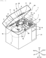
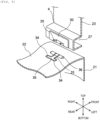
- a direction of top to bottom, a direction of left to right, and a direction of front to rear are based on directions of top to bottom, left to right, and front to rear indicated in Fig. 1 and Fig. 2 .
- the reagent dispensing probe uses a dispensing pipette to suck a reagent predetermined in a predetermined amount from each of reagent bottles 3, and dispenses the reagent sucked to a reaction container.
- the sample dispensing probe collects and supplies a sample as a biological sample, e.g., blood or urine, to the reaction container.
- the sample has been transported by sample transport means as will be described later.
- the reaction container When the reaction container has contained reaction solution in which the reagent and the sample are mixed, the reaction container is controlled at a predetermined temperature of the incubator where reaction in the reaction solution is promoted for a predetermined period of time.
- the detecting unit detects physical characteristics of the reaction solution as will be described later.
- the physical characteristics include an amount of emitted light, an amount of scattered light, an amount of transmitted light, a current value, a voltage value, and the like; however, the present invention is not limited thereto, and may employ a measurement unit for measuring known physical characteristics.
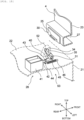
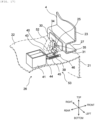
- the automatic analysis device 1 includes a safety cover 4 for covering a moving part.
- the safety cover 4 is supported by a hinge to be open and closed, for example, rearward.
- the safety cover 4 includes an interlock typically driven by, for example, a solenoid.
- the solenoid When the automatic analysis device 1 is in operation, the solenoid is powered on to lock and hold the safety cover 4 in a closed state.
- the solenoid When the automatic analysis device 1 is out of operation, the solenoid is powered off to put the safety cover 4 ready to be opened, enabling an operator to replace each of the reagent bottles 3.
- sample dispensing chip/reaction container supply means 7 (hereinafter, may be referred to as a chip rack) while being supplied in the automatic analysis device 1.
- the sample dispensing chip buffer 11 has the plurality of sample dispensing chips 10 temporarily mounted thereon.
- the sample dispensing means 6 moves to an area above the sample dispensing chip buffer 11 to grip any one of the sample dispensing chips 10.
- the reagent refrigerator has a lid for covering an upper portion of the reagent refrigerator, and the lid has a reagent bottle loading port 20.
- the reagent bottle loading port 20 is configured to place each of the reagent bottles 3 to the reagent disk 2 and remove the corresponding reagent bottle 3 from the reagent disk 2.
- the reagent bottle loading port 20 includes a reagent bottle loading port lid (not illustrated) for opening/closing the reagent bottle loading port 20, and further includes an interlock (not illustrated) using a solenoid or others.
- reaction solution is formed.
- the reaction solution is sucked from the reaction container 14 and supplied to detecting means 19 by a reaction solution aspiration nozzle 18.
- the detecting means 19 analyzes the reaction solution. Any known method may be applied to analyze the reaction solution. Further, the reaction solution may be analyzed while being held in the reaction container 14.
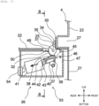
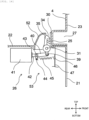
- Fig. 7 is an A-A cross-sectional view
- Fig. 8 is a B-B cross-sectional view
- Fig. 9 is a perspective view, each illustrating a locked state of the safety cover locking means in the automatic analysis device according to the first embodiment of the present invention.
- the locking portion 34 In side view in the direction of left to right, the locking portion 34 has a planar upper surface with a tapered shape downward; and at lower side, the locking portion 34 has a sectional surface with a smooth, substantially semi-cylindrical shape.
- each of the pair of locking portions 34 has a semicircular shape at its tip end and has its lower half in a smooth, hemispherical shape.
- the support rod portion 33 and the pair of locking portions 34 are smoothly combined with an R-shaped joint therebetween, and thus less prone to broken by stress concentration.
- the locking means 26 is provided in pairs at left and right sides, and has an entire left-to-right width larger than a left-to-right width between the tips of the pair of lock receiving means 25. With this configuration, the locking means 26 at left side engages with the lock receiving means 25 at left side, and the locking means 26 at right side engages with the lock receiving means 25 at right side.
- the connecting plate 40 has an end provided with a first spring peg portion 44, and a pull spring 45 has one end hooked on the first spring peg portion 44.
- the pull spring 45 has the other end hooked on a second spring peg portion 46 that is provided in a frame 47 fixed to the housing 21.
- the pull spring 45 has a spring force to pull the plunger 42 from the solenoid 41, and when the solenoid 41 is powered off, the pull spring 45 acts as a return spring.
- the recessed portion 49 which is formed in the T shape and provided on the work surface 22, has a one-end shape with a bottom surface 50 to prevent foreign substances or liquid from dropping into the housing 21.
- Each of the locking lever 35 and the lock receiving means 25 may be a molded component made of resin, thereby resulting at reasonable cost as well as smoother end surfaces and a more flexible shape than those of components made of metal, particularly a sheet metal. Accordingly, each of the locking lever 35 and the lock receiving means 25 has a reduced amount of protrusion from the safety cover 4, while maintaining a preferably reliable locking condition.
- the bottom surface of the locking portion 34 and the upper surface of the lock receiving means 25 abut each other and respectively form the acute angle.
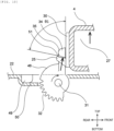
- Fig. 16 is an A-A cross-sectional view and Fig. 17 is a perspective view, each illustrating the locked state of the safety cover locking means according to the second embodiment.
- the solenoid 41 is powered on, and the plunger 42 is drawn toward the solenoid 41 by a force exceeding a pull force by the pull spring 45.
- This configuration draws the connecting shaft 39 via the connecting plate 40 toward the solenoid 41, causing the locking lever 35 to rotate about the first support shaft 31 clockwise on the drawings of Figs. 16 and 17 , and causing the locking portion 34 to move to above the lock receiving means 25.
- the safety cover locking means is in the locked state here.
- the recessed portion 49 provided on the work surface 22 to accommodate the locking portion 34, has the one-end shape to prevent foreign substances or liquid from dropping in through the clearance.
- the automatic analysis device is provided in a simple structure and is highly reliable.
Landscapes
- Physics & Mathematics (AREA)
- Chemical & Material Sciences (AREA)
- Biochemistry (AREA)
- Health & Medical Sciences (AREA)
- Life Sciences & Earth Sciences (AREA)
- Analytical Chemistry (AREA)
- General Health & Medical Sciences (AREA)
- General Physics & Mathematics (AREA)
- Immunology (AREA)
- Pathology (AREA)
- Electromagnetism (AREA)
- Engineering & Computer Science (AREA)
- Mechanical Engineering (AREA)
- Chemical Kinetics & Catalysis (AREA)
- Automatic Analysis And Handling Materials Therefor (AREA)
Applications Claiming Priority (2)
| Application Number | Priority Date | Filing Date | Title |
|---|---|---|---|
| JP2018097534A JP7032235B2 (ja) | 2018-05-22 | 2018-05-22 | 自動分析装置 |
| PCT/JP2019/005147 WO2019225075A1 (ja) | 2018-05-22 | 2019-02-13 | 自動分析装置 |
Publications (3)
| Publication Number | Publication Date |
|---|---|
| EP3798637A1 EP3798637A1 (en) | 2021-03-31 |
| EP3798637A4 EP3798637A4 (en) | 2022-03-09 |
| EP3798637B1 true EP3798637B1 (en) | 2025-04-09 |
Family
ID=68616649
Family Applications (1)
| Application Number | Title | Priority Date | Filing Date |
|---|---|---|---|
| EP19807151.6A Active EP3798637B1 (en) | 2018-05-22 | 2019-02-13 | Automated analysis device |
Country Status (5)
| Country | Link |
|---|---|
| US (1) | US11927032B2 (enExample) |
| EP (1) | EP3798637B1 (enExample) |
| JP (1) | JP7032235B2 (enExample) |
| CN (1) | CN112105934B (enExample) |
| WO (1) | WO2019225075A1 (enExample) |
Families Citing this family (5)
| Publication number | Priority date | Publication date | Assignee | Title |
|---|---|---|---|---|
| US11964605B1 (en) * | 2018-07-26 | 2024-04-23 | Amazon Technologies, Inc. | Hinge for sidewalk robot |
| JP7245106B2 (ja) | 2019-04-11 | 2023-03-23 | 株式会社日立ハイテク | インターロックユニットおよびそれを備えた自動分析装置 |
| JP7138783B2 (ja) * | 2019-04-11 | 2022-09-16 | 株式会社日立ハイテク | 自動分析装置 |
| JP7326113B2 (ja) * | 2019-10-31 | 2023-08-15 | 株式会社日立ハイテク | 検体容器把持装置及び検体搬送装置、接続装置 |
| EP4092420A4 (en) * | 2020-01-14 | 2024-02-28 | Hitachi High-Tech Corporation | AUTOMATIC ANALYZER |
Family Cites Families (24)
| Publication number | Priority date | Publication date | Assignee | Title |
|---|---|---|---|---|
| JPS5116173A (ja) | 1974-07-31 | 1976-02-09 | Masaichi Takami | Shamojitatetsukibeihanyoki |
| JPH0745435Y2 (ja) | 1989-12-01 | 1995-10-18 | 株式会社新来島どっく | 冷凍船のクーラルーム |
| JPH0516955A (ja) * | 1991-07-04 | 1993-01-26 | Seiko Epson Corp | 蓋体ロツク機構 |
| JPH0490232U (enExample) * | 1991-08-30 | 1992-08-06 | ||
| JP3338739B2 (ja) * | 1995-05-12 | 2002-10-28 | アンリツ株式会社 | 電磁波シールドボックス |
| JPH11238373A (ja) * | 1998-02-24 | 1999-08-31 | Sony Corp | 開閉蓋ロック機構 |
| JP3808651B2 (ja) * | 1999-01-13 | 2006-08-16 | 東芝メディカルシステムズ株式会社 | 自動分析装置 |
| JP3228722B2 (ja) * | 1999-03-03 | 2001-11-12 | 株式会社日立製作所 | 免疫分析装置 |
| JP2001111254A (ja) * | 1999-10-14 | 2001-04-20 | Sony Corp | 電子機器 |
| CN1281963C (zh) * | 2001-09-06 | 2006-10-25 | 希森美康株式会社 | 自动试样分析器及其部件 |
| CN2807967Y (zh) * | 2005-06-13 | 2006-08-23 | 沈子渊 | 改进的冲泡容器构造 |
| JP4499047B2 (ja) * | 2006-02-21 | 2010-07-07 | 富士フイルム株式会社 | 蓋の開閉機構 |
| JP2008021617A (ja) | 2006-07-14 | 2008-01-31 | Seiko Epson Corp | 液体材料、透明導電膜の形成方法、及び電気光学装置の製造方法 |
| JP2008216173A (ja) * | 2007-03-07 | 2008-09-18 | Toshiba Corp | 自動分析装置 |
| JP5362966B2 (ja) * | 2007-06-29 | 2013-12-11 | ユニ・チャーム株式会社 | 動物用トイレ |
| EP2030687A1 (de) * | 2007-08-13 | 2009-03-04 | Hamilton Bonaduz AG | Verschlussanordnung mit Schnappmechanismus |
| EP2031407B1 (en) * | 2007-08-29 | 2012-06-06 | F. Hoffmann-La Roche AG | Decapping system |
| JP2010052637A (ja) * | 2008-08-29 | 2010-03-11 | Alpha Corp | ステアリングロック装置 |
| JP2012026814A (ja) * | 2010-07-22 | 2012-02-09 | Hitachi High-Technologies Corp | 自動分析装置 |
| JP5808634B2 (ja) * | 2011-09-30 | 2015-11-10 | シスメックス株式会社 | 検体処理装置 |
| CN204407580U (zh) * | 2015-01-27 | 2015-06-17 | 江苏环力科技发展有限公司 | 一种水泵控制器用插座组件 |
| US10526130B2 (en) * | 2016-04-20 | 2020-01-07 | Yeti Coolers, Llc | Insulating container |
| US10138047B2 (en) * | 2016-04-20 | 2018-11-27 | Yeti Coolers, Llc | Spigot and spigot guard for an insulating container |
| CN112081504B (zh) * | 2020-09-30 | 2025-08-05 | 中元汇吉生物技术股份有限公司 | 真空腔室和舱门结构 |
-
2018
- 2018-05-22 JP JP2018097534A patent/JP7032235B2/ja active Active
-
2019
- 2019-02-13 CN CN201980018984.7A patent/CN112105934B/zh active Active
- 2019-02-13 EP EP19807151.6A patent/EP3798637B1/en active Active
- 2019-02-13 US US16/981,561 patent/US11927032B2/en active Active
- 2019-02-13 WO PCT/JP2019/005147 patent/WO2019225075A1/ja not_active Ceased
Also Published As
| Publication number | Publication date |
|---|---|
| US11927032B2 (en) | 2024-03-12 |
| EP3798637A4 (en) | 2022-03-09 |
| EP3798637A1 (en) | 2021-03-31 |
| JP7032235B2 (ja) | 2022-03-08 |
| WO2019225075A1 (ja) | 2019-11-28 |
| CN112105934A (zh) | 2020-12-18 |
| US20210062553A1 (en) | 2021-03-04 |
| CN112105934B (zh) | 2024-05-14 |
| JP2019203723A (ja) | 2019-11-28 |
Similar Documents
| Publication | Publication Date | Title |
|---|---|---|
| EP3798637B1 (en) | Automated analysis device | |
| US9835639B2 (en) | Gripping mechanism | |
| CN107407689B (zh) | 自动分析装置 | |
| JP6837362B2 (ja) | 自動分析装置 | |
| EP3508858B1 (en) | Sample measurement method and sample measurement device | |
| EP1805521A1 (en) | Instrument for efficient treatment of analytical devices | |
| CN109459576B (zh) | 体外诊断分析方法和系统 | |
| JP7423722B2 (ja) | 検体測定装置および検体測定方法 | |
| JP7321179B2 (ja) | 係止構造 | |
| JP2002340913A (ja) | 自動分析装置 | |
| JP7245106B2 (ja) | インターロックユニットおよびそれを備えた自動分析装置 | |
| JP2009036595A (ja) | 分析装置、洗浄装置、分注装置、攪拌装置および容器 | |
| JP7520004B2 (ja) | 自動分析装置及び試薬収容ユニット | |
| JP5216820B2 (ja) | 分注装置および核酸分析装置 | |
| JP7490893B2 (ja) | 自動分析装置 | |
| JP7281600B2 (ja) | 自動分析装置 | |
| JP7054616B2 (ja) | 自動分析装置 | |
| JP3347179B2 (ja) | 試料採取用プローブの供給装置 | |
| WO2022009458A1 (ja) | 開閉蓋装置およびそれを備えた自動分析装置 | |
| JPS62182664A (ja) | プレ−ト処理器を有する自動化液体処理装置及び方法 | |
| JP7138783B2 (ja) | 自動分析装置 | |
| JP7574185B2 (ja) | 自動分析装置及びその試薬容器蓋開閉機構 | |
| CN115867809A (zh) | 自动分析装置 |
Legal Events
| Date | Code | Title | Description |
|---|---|---|---|
| STAA | Information on the status of an ep patent application or granted ep patent |
Free format text: STATUS: THE INTERNATIONAL PUBLICATION HAS BEEN MADE |
|
| PUAI | Public reference made under article 153(3) epc to a published international application that has entered the european phase |
Free format text: ORIGINAL CODE: 0009012 |
|
| STAA | Information on the status of an ep patent application or granted ep patent |
Free format text: STATUS: REQUEST FOR EXAMINATION WAS MADE |
|
| 17P | Request for examination filed |
Effective date: 20201222 |
|
| AK | Designated contracting states |
Kind code of ref document: A1 Designated state(s): AL AT BE BG CH CY CZ DE DK EE ES FI FR GB GR HR HU IE IS IT LI LT LU LV MC MK MT NL NO PL PT RO RS SE SI SK SM TR |
|
| AX | Request for extension of the european patent |
Extension state: BA ME |
|
| DAV | Request for validation of the european patent (deleted) | ||
| DAX | Request for extension of the european patent (deleted) | ||
| A4 | Supplementary search report drawn up and despatched |
Effective date: 20220207 |
|
| RIC1 | Information provided on ipc code assigned before grant |
Ipc: G01N 35/04 20060101ALI20220201BHEP Ipc: G01N 35/02 20060101ALI20220201BHEP Ipc: H05K 5/03 20060101ALI20220201BHEP Ipc: G01N 35/00 20060101AFI20220201BHEP |
|
| GRAP | Despatch of communication of intention to grant a patent |
Free format text: ORIGINAL CODE: EPIDOSNIGR1 |
|
| STAA | Information on the status of an ep patent application or granted ep patent |
Free format text: STATUS: GRANT OF PATENT IS INTENDED |
|
| INTG | Intention to grant announced |
Effective date: 20241030 |
|
| GRAS | Grant fee paid |
Free format text: ORIGINAL CODE: EPIDOSNIGR3 |
|
| GRAA | (expected) grant |
Free format text: ORIGINAL CODE: 0009210 |
|
| STAA | Information on the status of an ep patent application or granted ep patent |
Free format text: STATUS: THE PATENT HAS BEEN GRANTED |
|
| AK | Designated contracting states |
Kind code of ref document: B1 Designated state(s): AL AT BE BG CH CY CZ DE DK EE ES FI FR GB GR HR HU IE IS IT LI LT LU LV MC MK MT NL NO PL PT RO RS SE SI SK SM TR |
|
| REG | Reference to a national code |
Ref country code: GB Ref legal event code: FG4D |
|
| REG | Reference to a national code |
Ref country code: CH Ref legal event code: EP |
|
| REG | Reference to a national code |
Ref country code: DE Ref legal event code: R096 Ref document number: 602019068479 Country of ref document: DE |
|
| REG | Reference to a national code |
Ref country code: IE Ref legal event code: FG4D |
|
| REG | Reference to a national code |
Ref country code: NL Ref legal event code: MP Effective date: 20250409 |
|
| PG25 | Lapsed in a contracting state [announced via postgrant information from national office to epo] |
Ref country code: NL Free format text: LAPSE BECAUSE OF FAILURE TO SUBMIT A TRANSLATION OF THE DESCRIPTION OR TO PAY THE FEE WITHIN THE PRESCRIBED TIME-LIMIT Effective date: 20250409 |
|
| REG | Reference to a national code |
Ref country code: AT Ref legal event code: MK05 Ref document number: 1783956 Country of ref document: AT Kind code of ref document: T Effective date: 20250409 |
|
| PG25 | Lapsed in a contracting state [announced via postgrant information from national office to epo] |
Ref country code: FI Free format text: LAPSE BECAUSE OF FAILURE TO SUBMIT A TRANSLATION OF THE DESCRIPTION OR TO PAY THE FEE WITHIN THE PRESCRIBED TIME-LIMIT Effective date: 20250409 Ref country code: PT Free format text: LAPSE BECAUSE OF FAILURE TO SUBMIT A TRANSLATION OF THE DESCRIPTION OR TO PAY THE FEE WITHIN THE PRESCRIBED TIME-LIMIT Effective date: 20250811 Ref country code: ES Free format text: LAPSE BECAUSE OF FAILURE TO SUBMIT A TRANSLATION OF THE DESCRIPTION OR TO PAY THE FEE WITHIN THE PRESCRIBED TIME-LIMIT Effective date: 20250409 |
|
| REG | Reference to a national code |
Ref country code: LT Ref legal event code: MG9D |
|
| PG25 | Lapsed in a contracting state [announced via postgrant information from national office to epo] |
Ref country code: GR Free format text: LAPSE BECAUSE OF FAILURE TO SUBMIT A TRANSLATION OF THE DESCRIPTION OR TO PAY THE FEE WITHIN THE PRESCRIBED TIME-LIMIT Effective date: 20250710 Ref country code: NO Free format text: LAPSE BECAUSE OF FAILURE TO SUBMIT A TRANSLATION OF THE DESCRIPTION OR TO PAY THE FEE WITHIN THE PRESCRIBED TIME-LIMIT Effective date: 20250709 |
|
| PG25 | Lapsed in a contracting state [announced via postgrant information from national office to epo] |
Ref country code: PL Free format text: LAPSE BECAUSE OF FAILURE TO SUBMIT A TRANSLATION OF THE DESCRIPTION OR TO PAY THE FEE WITHIN THE PRESCRIBED TIME-LIMIT Effective date: 20250409 |
|
| PG25 | Lapsed in a contracting state [announced via postgrant information from national office to epo] |
Ref country code: BG Free format text: LAPSE BECAUSE OF FAILURE TO SUBMIT A TRANSLATION OF THE DESCRIPTION OR TO PAY THE FEE WITHIN THE PRESCRIBED TIME-LIMIT Effective date: 20250409 |
|
| PG25 | Lapsed in a contracting state [announced via postgrant information from national office to epo] |
Ref country code: HR Free format text: LAPSE BECAUSE OF FAILURE TO SUBMIT A TRANSLATION OF THE DESCRIPTION OR TO PAY THE FEE WITHIN THE PRESCRIBED TIME-LIMIT Effective date: 20250409 |
|
| PG25 | Lapsed in a contracting state [announced via postgrant information from national office to epo] |
Ref country code: AT Free format text: LAPSE BECAUSE OF FAILURE TO SUBMIT A TRANSLATION OF THE DESCRIPTION OR TO PAY THE FEE WITHIN THE PRESCRIBED TIME-LIMIT Effective date: 20250409 |
|
| PG25 | Lapsed in a contracting state [announced via postgrant information from national office to epo] |
Ref country code: RS Free format text: LAPSE BECAUSE OF FAILURE TO SUBMIT A TRANSLATION OF THE DESCRIPTION OR TO PAY THE FEE WITHIN THE PRESCRIBED TIME-LIMIT Effective date: 20250709 |
|
| PG25 | Lapsed in a contracting state [announced via postgrant information from national office to epo] |
Ref country code: IS Free format text: LAPSE BECAUSE OF FAILURE TO SUBMIT A TRANSLATION OF THE DESCRIPTION OR TO PAY THE FEE WITHIN THE PRESCRIBED TIME-LIMIT Effective date: 20250809 |
|
| PG25 | Lapsed in a contracting state [announced via postgrant information from national office to epo] |
Ref country code: LV Free format text: LAPSE BECAUSE OF FAILURE TO SUBMIT A TRANSLATION OF THE DESCRIPTION OR TO PAY THE FEE WITHIN THE PRESCRIBED TIME-LIMIT Effective date: 20250409 |