EP3798336B1 - Method for producing electrolytic copper foil - Google Patents
Method for producing electrolytic copper foil Download PDFInfo
- Publication number
- EP3798336B1 EP3798336B1 EP20804154.1A EP20804154A EP3798336B1 EP 3798336 B1 EP3798336 B1 EP 3798336B1 EP 20804154 A EP20804154 A EP 20804154A EP 3798336 B1 EP3798336 B1 EP 3798336B1
- Authority
- EP
- European Patent Office
- Prior art keywords
- copper foil
- additive
- electrolytic copper
- electrolytic
- thiourea
- Prior art date
- Legal status (The legal status is an assumption and is not a legal conclusion. Google has not performed a legal analysis and makes no representation as to the accuracy of the status listed.)
- Active
Links
Images
Classifications
-
- C—CHEMISTRY; METALLURGY
- C25—ELECTROLYTIC OR ELECTROPHORETIC PROCESSES; APPARATUS THEREFOR
- C25D—PROCESSES FOR THE ELECTROLYTIC OR ELECTROPHORETIC PRODUCTION OF COATINGS; ELECTROFORMING; APPARATUS THEREFOR
- C25D3/00—Electroplating: Baths therefor
- C25D3/02—Electroplating: Baths therefor from solutions
- C25D3/38—Electroplating: Baths therefor from solutions of copper
-
- C—CHEMISTRY; METALLURGY
- C25—ELECTROLYTIC OR ELECTROPHORETIC PROCESSES; APPARATUS THEREFOR
- C25D—PROCESSES FOR THE ELECTROLYTIC OR ELECTROPHORETIC PRODUCTION OF COATINGS; ELECTROFORMING; APPARATUS THEREFOR
- C25D1/00—Electroforming
- C25D1/04—Wires; Strips; Foils
-
- C—CHEMISTRY; METALLURGY
- C25—ELECTROLYTIC OR ELECTROPHORETIC PROCESSES; APPARATUS THEREFOR
- C25D—PROCESSES FOR THE ELECTROLYTIC OR ELECTROPHORETIC PRODUCTION OF COATINGS; ELECTROFORMING; APPARATUS THEREFOR
- C25D1/00—Electroforming
-
- C—CHEMISTRY; METALLURGY
- C25—ELECTROLYTIC OR ELECTROPHORETIC PROCESSES; APPARATUS THEREFOR
- C25D—PROCESSES FOR THE ELECTROLYTIC OR ELECTROPHORETIC PRODUCTION OF COATINGS; ELECTROFORMING; APPARATUS THEREFOR
- C25D17/00—Constructional parts, or assemblies thereof, of cells for electrolytic coating
- C25D17/10—Electrodes, e.g. composition, counter electrode
-
- H—ELECTRICITY
- H01—ELECTRIC ELEMENTS
- H01M—PROCESSES OR MEANS, e.g. BATTERIES, FOR THE DIRECT CONVERSION OF CHEMICAL ENERGY INTO ELECTRICAL ENERGY
- H01M4/00—Electrodes
- H01M4/02—Electrodes composed of, or comprising, active material
- H01M4/64—Carriers or collectors
- H01M4/66—Selection of materials
- H01M4/661—Metal or alloys, e.g. alloy coatings
-
- H—ELECTRICITY
- H05—ELECTRIC TECHNIQUES NOT OTHERWISE PROVIDED FOR
- H05K—PRINTED CIRCUITS; CASINGS OR CONSTRUCTIONAL DETAILS OF ELECTRIC APPARATUS; MANUFACTURE OF ASSEMBLAGES OF ELECTRICAL COMPONENTS
- H05K1/00—Printed circuits
- H05K1/02—Details
- H05K1/0213—Electrical arrangements not otherwise provided for
- H05K1/0237—High frequency adaptations
-
- H—ELECTRICITY
- H05—ELECTRIC TECHNIQUES NOT OTHERWISE PROVIDED FOR
- H05K—PRINTED CIRCUITS; CASINGS OR CONSTRUCTIONAL DETAILS OF ELECTRIC APPARATUS; MANUFACTURE OF ASSEMBLAGES OF ELECTRICAL COMPONENTS
- H05K1/00—Printed circuits
- H05K1/02—Details
- H05K1/03—Use of materials for the substrate
-
- H—ELECTRICITY
- H05—ELECTRIC TECHNIQUES NOT OTHERWISE PROVIDED FOR
- H05K—PRINTED CIRCUITS; CASINGS OR CONSTRUCTIONAL DETAILS OF ELECTRIC APPARATUS; MANUFACTURE OF ASSEMBLAGES OF ELECTRICAL COMPONENTS
- H05K1/00—Printed circuits
- H05K1/02—Details
- H05K1/09—Use of materials for the conductive, e.g. metallic pattern
-
- H—ELECTRICITY
- H05—ELECTRIC TECHNIQUES NOT OTHERWISE PROVIDED FOR
- H05K—PRINTED CIRCUITS; CASINGS OR CONSTRUCTIONAL DETAILS OF ELECTRIC APPARATUS; MANUFACTURE OF ASSEMBLAGES OF ELECTRICAL COMPONENTS
- H05K2201/00—Indexing scheme relating to printed circuits covered by H05K1/00
- H05K2201/03—Conductive materials
- H05K2201/0332—Structure of the conductor
- H05K2201/0335—Layered conductors or foils
- H05K2201/0355—Metal foils
-
- Y—GENERAL TAGGING OF NEW TECHNOLOGICAL DEVELOPMENTS; GENERAL TAGGING OF CROSS-SECTIONAL TECHNOLOGIES SPANNING OVER SEVERAL SECTIONS OF THE IPC; TECHNICAL SUBJECTS COVERED BY FORMER USPC CROSS-REFERENCE ART COLLECTIONS [XRACs] AND DIGESTS
- Y02—TECHNOLOGIES OR APPLICATIONS FOR MITIGATION OR ADAPTATION AGAINST CLIMATE CHANGE
- Y02E—REDUCTION OF GREENHOUSE GAS [GHG] EMISSIONS, RELATED TO ENERGY GENERATION, TRANSMISSION OR DISTRIBUTION
- Y02E60/00—Enabling technologies; Technologies with a potential or indirect contribution to GHG emissions mitigation
- Y02E60/10—Energy storage using batteries
Definitions
- the present invention relates to a method for producing an electrolytic copper foil.
- the present invention relates to a technique for providing an electrolytic copper foil: which is useful as, for example, a negative electrode material for a secondary battery or a material for an electronic circuit board; which exhibits an electrical conductivity of 99% or more; which achieves both a high tensile strength of 500 MPa or more and a high elongation percentage of 5.5% or more although the electrolytic copper foil is thin, as thin as 10 ⁇ m or less; in which a rough surface is a flat surface having a low surface roughness; and which has an extremely high practical value.
- an electrolytic copper foil is produced by a method as follows, to which a plating technique is applied.
- An aqueous solution composed of sulfuric acid and copper sulfate is used as an electrolytic solution; this electrolytic solution is filled between a cylindrically shaped titanium drum which is a cathode and an insoluble anode which is an anode; a direct current is passed between both electrodes, and thereby copper is deposited on the cathode surface and a copper foil is formed.
- the cathode drum is rotating at a constant speed, and the deposited electrolytic copper is peeled from the drum surface to be wound continuously at a stage where the deposited electrolytic copper has a particular thickness.
- an electrolytic copper foil as a request for production.
- a surface of the peeled copper foil which was in contact with the drum is referred to as a "glossy surface”
- a surface which is opposite to this glossy surface and is on the side of the electrolytic solution is referred to a "rough surface”
- the electrolytic copper foil at this stage is referred to as an "untreated electrolytic copper foil”.
- an electrolytic copper foil when used for an electronic circuit board, various surface treatments for the purpose of improving adhesiveness with a resin, and imparting chemical resistance and rust preventiveness, and for other purposes are performed on the untreated electrolytic copper foil.
- the electrolytic coper foil which has gone through various surface treatment steps is referred to as a "treated electrolytic copper foil" in contrast with the above-described untreated electrolytic copper foil.
- Patent Literature 1 proposes a technique for producing an electrolytic copper alloy foil containing tungsten and the balance composed of copper by electrolytic deposition, wherein a thiourea-based compound, a tungsten salt, and a chloride ion are added to a sulfuric acid-copper sulfate electrolytic solution. It is described that according to this technique, an electrolytic copper alloy foil having an electrolytic deposition surface which has a low profile, having large mechanical strength, and having mechanical strength which is less likely to be changed even if it is heated at 300°C or higher is obtained. It is to be noted that the thickness of the tungsten-containing untreated electrolytic copper foil which is obtained in Examples in Patent Literature 1 is 12 ⁇ m.
- Patent Literature 2 proposes that a problem of rough roughness resulting in occurrence of peeling of tin plating, caused by formation of crest and trough shapes on a surface on the side of the "rough surface” in the previously described "untreated electrolytic copper foil, is solved by ameliorating an electrolytic solution. Specifically, it is described that when a nonionic water-soluble polymer, a sulfonate salt of an active organic sulfur compound, a thiourea-based compound, and a chlorine ion are allowed to coexist in an electrolytic solution containing a sulfuric acid-copper sulfate aqueous solution, a resultant electrolytic copper foil is thereby made satisfactory as described below.
- the resultant electrolytic copper foil is made such that it exhibits a low rough surface having a roughness of the rough surface of 2 ⁇ m or less, a particular crystal structure which is ascertained through observation on the rough surface side by X-ray diffraction, and a high tensile strength, as high as a tensile strength of 500 MPa or more after heating at 180°C for 1 hour.
- the untreated electrolytic copper electrode which is described to be obtained in Examples in Patent Literature 2 has a thickness of 18 ⁇ m.
- Patent Literature 3 intends to provide a copper foil having useful properties as a copper foil for a high-frequency circuit.
- the state of a granular crystal structure on the surface of an untreated electrolytic copper foil is controlled by controlling the foil production condition for a copper foil, and, further, the surface is subjected to electrolytic etching, thereby enabling production of a copper foil having an excellent transmission loss in a high-frequency region and having high peel strength.
- an electrolytic copper foil produced with a copper plating solution to which a compound having a mercapto group, a chloride ion, and a low-molecular-weight glue having a molecular weight of 10000 or lower or/and a macromolecular polysaccharide are added has a granular crystal structure.
- Patent Literature 3 it is described that having properties of a tensile strength of 20 kN/m 2 or more and an elongation percentage of 3% or more is desirable because of handling properties in a line.
- Patent Literature 3 relates to a technique based on the presupposition that electrolytic etching is performed on the surface of an untreated electrolytic copper foil later, and therefore the thickness of an untreated electrolytic copper foil which is obtained in Examples is 12 ⁇ m.
- Patent literature 4 describes a method for preparing an electrolytic copper foil to be used as electrode for lithium batteries, the method comprising the use of a sulfuric acid-copper sulfate aqueous electrolytic solution.
- Patent Literature 1 is for obtaining a tungsten-containing untreated electrolytic copper foil (hereinafter, simply referred to as electrolytic copper foil), the copper foil contains a heavy metal other than copper, and therefore there is a fatal problem that the copper foil is inferior to pure copper foil in electrical conductivity even though the copper foil exhibits a high tensile strength of 500 MPa or more.
- the technique described in Patent Literature 2 intends to provide an electrolytic copper foil achieving that the roughness of the rough surface is 2.0 ⁇ m or less and the tensile strength after heating at 180°C for 1 hour is 500 MPa or more, but as the required performance to the electrolytic copper foil of late, exhibiting higher tensile strength has been desired.
- the thickness of the electrolytic copper foil given as an example in the technique described in Patent Literature 2 is thick, as thick as 18 ⁇ m, and therefore the technique is not the one that sufficiently meets a request of late for making an electrolytic copper foil light, thin, short, and small corresponding to reduction in size and weight of a product, reduction in material costs, and effective utilization of resources.
- Patent Literature 3 is a technique for making the roughness of a rough surface 2.5 ⁇ m or less after an electrolytic etching treatment of an untreated electrolytic copper foil, and the object is different from the present invention and the other conventional techniques described above.
- the thickness of any of the electrolytic copper foils which are described to be obtained by the conventional techniques is thick, as thick as 12 ⁇ m or more, but to meet the reduction in size and weight of a product of late, realization of high performance in a thinner electrolytic copper foil is desired. Also from the viewpoint of effective utilization of resources of late, a technique for providing an electrolytic copper foil having a thinner thickness and realizing excellent performance simply and economically has been hoped for.
- an electrolytic copper foil having a thinner thickness of 10 ⁇ m or less it is difficult to enhance the mechanical strength in an electrolytic copper foil having a thinner thickness of 10 ⁇ m or less, and besides, an electrolytic copper foil the mechanical strength of which is enhanced has, on the other hand, a serious problem in production that elongation is impaired.
- an electrolytic copper foil not having a sufficient elongation percentage the foil is cut in some cases when an obtained electrolytic copper foil is wound onto a drum to be made into a product, and in that case, the yield of the product is drastically impaired.
- the mechanical strength and elongation percentage in an electrolytic copper foil are in a trade-off relationship, and therefore it is industrially difficult to put the electrolytic copper foil having a thinner thickness of 10 ⁇ m or less into practical use unless a technique that can achieve both of the mechanical strength and the elongation percentage is provided.
- the electrolytic copper foil is a more advantageous material with respect to workability, processability, and the like as compared to conventional materials.
- an object of the present invention is to develop a technique for providing an electrolytic copper foil: which has not been realized by conventional techniques; which can satisfactorily be wound onto a drum; which is excellent in workability and a yield; and which is extremely useful in practical use.
- the object of the present invention is to develop a technique for providing an electrolytic copper foil which is a thin electrolytic copper foil having an electrical conductivity of 99% or more and having a thickness of 10 ⁇ m or less, and in which the problem of the "bend (curl)" is suppressed, the front side and the rear side are flat, as flat as having a surface roughness of 2.5 ⁇ m or less on both of the front side and the rear side, the tensile strength is 500 MPa or more, and the elongation percentage is 5.5% or more.
- Another object of the present invention is to produce an electrolytic copper foil exhibiting excellent performance described above and containing pure copper by a simple method in which additives in an electrolytic solution are merely devised without using a heavy metal separately and without putting another heavy metal into the crystal structure of the electrolytic copper foil.
- a method for producing an electrolytic copper foil including forming an electrolytic copper foil by: using, as an electrolytic solution, a sulfuric acid-copper sulfate aqueous solution not containing a heavy metal other than a copper metal; using an insoluble anode having a surface of a substrate covered with at least one of a platinum group metal and/or an oxide thereof, and a cathode drum facing the insoluble anode; and passing a direct current between these electrodes, wherein
- Preferred embodiments of the method for producing an electrolytic copper foil of the present invention include the followings.
- the additive (D) and the additive (A) are each added in a ratio such that (D)/(A) is 0.3 to 0.6.
- the electrolytic copper foil is for a negative electrode material for a secondary battery.
- the electrolytic copper foil is for a high-frequency circuit.
- the surface roughness is 1.8 ⁇ m or less on both of the front side and the rear side.
- the tensile strength is 500 MPa or more in both of the electrolytic copper foil immediately after producing the foil and the electrolytic copper foil 48 hours after producing the foil.
- the electrolytic copper foil is for a negative electrode material for a secondary battery.
- the electrolytic copper foil is for a high-frequency circuit.
- an electrolytic copper foil product which is a thin electrolytic copper foil having an electrical conductivity of 99% or more and having a thickness of 10 ⁇ m or less; and in which the problem of the "bend (curl)" is suppressed, both of the front side and the rear side are flat, as flat as having a surface roughness of 2.5 ⁇ m or less, the tensile strength is 500 MPa or more, and the elongation percentage is 5.5% or more can be provided.
- an electrolytic copper foil product which has not been realized in conventional techniques; which is wound satisfactorily onto a drum; which is excellent in workability and a product yield; and which is extremely useful in practical use is provided.
- a material which is more advantageous with respect to workability and processability as compared to conventional materials the material being such that an electrolytic copper foil exhibits sufficiently high strength not only immediately after production but also at a point in time when a treatment for obtaining the "treated electrolytic copper foil" needs to be performed after producing the electrolytic copper foil, for example, 48 hours after producing the electrolytic copper foil.
- a method for producing an electrolytic copper foil by which an electrolytic copper foil which have not been realized by the conventional techniques and which has excellent properties can be obtained through a simple method in which additives in an electrolytic solution are merely devised, is provided, and therefore the method is extremely industrially useful.
- an electrolytic copper foil having excellent properties which have never existed in the past is obtained although the number of types of additives to be used is small, on top of that, all the raw materials are general-purpose raw materials, and the use amounts thereof are smaller as compared to those in conventional methods, and therefore an electrolytic copper foil which is also useful in terms of economy and effective utilization of resources is provided.
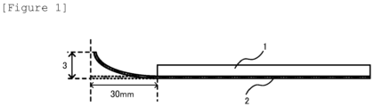
- Figure 1 is an explanatory drawing schematically showing a method for performing relative evaluation of a state of occurrence of a bend (curl) used for evaluating an electrolytic copper foil in the present invention.
- An electrolytic copper foil provided by the method of the present invention is prepared using an electrolytic solution not containing a heavy metal other than a copper metal and is therefore basically composed of pure copper.
- Patent Literature 1 which is previously described as a conventional technique, a copper foil containing tungsten is made by electrolytic deposition, and therefore the electrical conductivity is lowered as compared to pure copper, so that a product having achieved an electrical conductivity of 99% or more is not made.
- the copper foil which is provided by the technique of Patent Literature 1 has a serious problem that it is inferior in electrical conductivity which is basic performance that is extremely important in the application of a copper foil even if it is a suitable electrolytic copper foil in the strength thereof.
- the electrolytic copper foil provided by the method of the present invention is characterized by having a tensile strength of 500 MPa or more and having an elongation percentage of 5.5% or more although the electrolytic copper foil is thin, as thin as 10 ⁇ m or less.
- a copper foil is widely used as, for example, a printed wiring board in which the copper foil is pasted together with a polyimide film; however, improvements in the strength of a copper foil have been required because wiring integrated types have been increasing in recent years.
- a thinner copper foil is desired.
- the present invention realizes an electrolytic copper foil which has achieved both of high strength and a sufficient elongation percentage necessary for obtaining a product with a satisfactory yield in production although the electrolytic copper foil is an electrolytic copper foil having a thin thickness, as thin as a thickness of 10 ⁇ m or less, for example, 7 to 9 ⁇ m.
- the copper foil is formed by using an electrolytic solution containing copper, and passing a direct current between both electrodes, thereby depositing copper on a cylindrical drum of a cathode, and therefore a thin foil can be obtained more simply than in a method for obtaining a copper foil excellent in glossiness by rolling.
- the strength of an electrolytic copper foil having an electrical conductivity of 99% is enhanced by a conventional method, when the electrolytic copper is peeled from the cylindrical drum and is continuously wound to obtain an electrolytic copper foil product, a problem that a part of the copper foil is cut, and, in some cases, a problem that the copper foil is cut off in the middle of being wound occur unless the elongation percentage of the copper foil is sufficient.
- the electrolytic copper foil provided by the method of the present invention is such that the occurrence of the "bend (curl)" is suppressed and has properties which have not existed in the past.
- the electrolytic copper foil provided by the method of the present invention is made such that the electrolytic copper foil exhibits high strength and a sufficient elongation percentage not only immediately after producing the foil but also even after the elapse of, for example, 48 hours after producing the foil in addition to suppression of the occurrence of the "bend (curl)".
- the surface of the electrolytic copper foil which was in contact with the drum, is flat as can be understood from the fact that the surface is referred to as the "glossy surface".
- the surface on the other side where the electrolytic copper foil is immersed in an electrolytic solution clearly has unevenness and has a larger roughness as compared to the "glossy” surface as can be understood from the fact that the surface is referred to as the "rough surface”.
- the electrolytic copper foil is extremely useful as, for example, a base body copper foil for a negative electrode of a secondary battery, wherein being glossy surfaces are desired.
- the electrolytic copper foil which is provided by the method of the present invention more preferably have a roughness of 2.0 ⁇ m or less, still more preferably 1.8 ⁇ m or less on both of the front side and the rear side.
- the glossy surface exhibits a surface roughness of 1.0 ⁇ m or less.
- the present inventors have conducted studies on realization of achieving both the high strength and the satisfactory elongation percentage, which are contrary to each other with respect to an electrolytic copper foil, in an electrolytic copper foil having a thin thickness of 10 ⁇ m or less, and, in addition to these requests, on simply obtaining an electrolytic copper foil stably having a surface roughness of the rough surface of 2.5 ⁇ m or less.
- the present inventors have conducted detailed studies particularly under the recognition that when all the problems are solved by devising the additives for an electrolytic solution for use in obtaining an electrolytic copper foil, an extremely useful technique is completed.
- the constitution of an electrolytic solution is made such that the constitution does not allow a heavy metal other than a copper metal to be contained in order to obtain an electrolytic copper foil having a high electrical conductivity of 99% or more. Therefore, the present invention is basically a technique for providing an electrolytic copper foil of pure copper. It is to be noted that the present invention does not deny even the existence of a heavy metal contaminating a copper foil by being inevitably contained in an electrolytic solution in a production process.
- the heavy metal specified in the present invention means, for example, W (tungsten), which is proposed in the previously mentioned technique of Patent Literature 1.
- W tungsten
- tungsten which is a metal other than copper
- Patent Literature 1 the high tensile strength is realized in an electrolytic foil of "Cu-W” alloy.
- this technique can realize high tensile strength, but has fatal problems that the elongation percentage is small, and, among others, high electrical conductivity which a copper foil intrinsically has, is impaired.
- the present inventors have conducted studies in order to obtain an industrially extremely useful electrolytic copper foil having properties which have not existed in the past by devising the additives for an electrolytic solution, not by intercalating another heavy metal in a copper foil to achieve high strengthening in a thin electrolytic copper foil having a thickness of 10 ⁇ m or less, as in the above-described technique. Specifically, the present inventors have conducted diligent studies in order to obtain an electrolytic copper foil which realizes high tensile strength, besides, exhibits a sufficient elongation percentage which is in a tradeoff relationship with the high tensile strength and is not inconvenient for producing the electrolytic copper foil, and further has a surface roughness of 2.5 ⁇ m or less on both of the front side and the rear side.
- the roughness be more preferably 2.0 ⁇ m or less, and further, 1.8 ⁇ m or less on both of the front surface and the rear surface in the application, such as, for example, a base body copper foil for a negative electrode of a secondary battery, where the rough surface is desired to be a glossy surface.
- both of the front side and the rear side ideally have the same roughness.
- An electrolytic copper foil has a technical problem to be solved that, as mentioned previously, the "bend (curl)" occurs to an electrolytic copper foil obtained by a conventional technique and having a thin thickness, in addition to achieving the above-described properties.
- the satisfactory strength of an electrolytic copper foil immediately after producing the foil be retained even after, for example, 48 hours after producing the foil taking an influence on the production of products for various applications utilizing the electrolytic copper foil into consideration.
- the present inventors have recognized that when an electrolytic copper foil by which these problems have been solved can be provided, the electrolytic copper foil is an industrially extremely useful material.
- an electrolytic copper foil which satisfies all the above-described properties can be realized by an extremely simple method such that the following five types of additives are each added in the amount specified in the present invention in a well-balanced manner to an electrolytic solution containing a sulfuric acid-copper sulfate aqueous solution, and have thereby reached the present invention. That is, the production method of the present invention is characterized in that in an electrolytic solution, the following five types of additives of (A) to (E) are contained each in a small amount in the range described below, and the additive (D) and the additive (A) are each added in a ratio such that (D)/(A) is 0.2 to 0.7.
- these additives will be described.
- a soluble type or dispersible type nonionic organic compound having a molecular weight of 200000 to 500000 is used as the additive (A) and is added in such a way that the concentration is 5 to 15 ppm in the electrolytic solution.
- a water-soluble organic compound is hydroxyethyl cellulose, polyglycerin, or acetylene glycol. These compounds may appropriately be used together. For example, when hydroxyethyl cellulose is used, hydroxyethyl cellulose having a viscosity of 80 to 130/mPa ⁇ s, of 300 to 400/mPa ⁇ s, of 400 to 800/mPa ⁇ s, and the like at 2% and at 25°C can suitably be used.
- the reason that the excellent effects of the present invention are obtained by adding the additive (A) to the electrolytic solution is not certain, but the present inventors consider that the reason is as described below.
- the present inventors consider that the high-molecular-weight (A) component is dispersed when electrolysis acts thereon, thereby allowing copper crystals to grow, as a result, in the electrolytic copper foil of the present invention, the elongation percentage of the copper foil at normal temperature and at a high temperature can be improved, and further, high strength can be retained even after the elapse of 48 hours after producing the foil.
- the chlorine ion functions as a carrier that carries the other additive components effectively in an electrolytic solution in which electrolysis is being performed, and particularly when the addition amount of the high-molecular-weight additive (A) is large, the amount of the carrier is insufficient, and therefore adding a somewhat larger amount of the chlorine ion is effective.
- the additive (A) needs to be added in such a way that the concentration in the electrolytic solution is 5 to 15 ppm. More preferably, the additive (A) is added in a range such that the concentration is 5 ppm or more and less than 10 ppm.
- a collagen peptide as a low-molecular-weight organic compound having a molecular weight of 7000 or lower and 2000 or higher is used as the additive (B) and is added in such a way that the concentration is 6.5 to 15 ppm in the electrolytic solution.
- a preferred additive (B) include a low-molecular-weight collagen peptide obtained by decomposing protein, the collagen peptide having a molecular weight of 7000 or lower and 2000 or higher, for example, having a molecular weight of about 3000 to about 5000.
- the collagen peptide having the above-described molecular weight can be dissolved in the electrolytic solution stably and is easily available, and is therefore suitable for the present invention.
- the collagen peptide is obtained in such a way that gelatin obtained by subjecting collagen to heat denaturation is decomposed by an enzymatic treatment to lower the molecular weight to several hundreds to several thousands, has been attracting attention also as health food in recent years, and has been widely utilized as a raw material for cosmetics or a raw material for industrial use.
- raw materials for collagen animals, such as cattle and pigs, and, besides, fish skin and scales of flounders, salmons, and the like are used.
- the collagen peptide may be the one obtained by organic synthesis.
- the collagen peptide which is suitable as the additive (B) in the present invention and has a molecular weight of 7000 or lower the one sold on the market can easily available.
- the collagen peptide derived from animal collagen include NIPPI PEPTIDE PBF and NIPPI PEPTIDE PRA (each manufactured by Nippi, Incorporated), SCP-5000, SCP-3100 (each manufactured by Nitta Gelatin Inc.), Collagen Peptide DS (manufactured by Kyowa Hi foods Co., Ltd.), and Pharconix CTP (manufactured by ICHIMARU PHARCOS Co., Ltd.).
- a substance having an amino acid composition similar to that in the animal collagen is preferable, and examples thereof include a peptide derived from a carrot as a peptide similar to collagen.
- Collagen is a main protein that constitutes connective tissue of an animal and is contained abundantly in a bone, a tendon, skin, a vascular wall, and the like. Collagen has a one or a plurality of triple helical structures in a molecule, and various types of collagen each having a different amino acid sequence of a polypeptide chain that constitutes the collagen exist.
- Gelatin which is a product of denaturation of collagen, is a water-soluble protein which is obtained by extracting a raw material containing collagen with hot (heated) water and has a molecular weight of 300000 to several tens of thousands.
- the additive (B) is added in such a way that the concentration is 6.5 to 15 ppm in the electrolytic solution.
- the additive (B) is preferably added in such a way that the concentration is 7 to 12 ppm.
- the additive (B) which is a low-molecular-weight component, does not affect the tensile strength and elongation of a resultant electrolytic copper foil regardless of whether the additive (B) is added to the electrolytic solution or not.
- each of these additives is more preferably added in a ratio such that (C)/(B) is, for example, 0.2 to 0.6, still more preferably in a ratio such that (C)/(B) is about 0.2 to about 0.4.
- a sulfonate salt of an active organic sulfur compound is used as the additive (C) and is added in a range of 2 to 10 ppm in the electrolytic solution.
- the sulfonate salt of an active organic sulfur compound is preferably added in such a way that the amount is 2 to 6 ppm.
- the sulfonate salt of an active organic sulfur compound is selected from sodium 3-mercapto-1-propanesulfonate and disodium bis(3-sulfopropyl)disulfide.
- the sulfonate salt of an active organic sulfur compound has conventionally been used as a gloss agent, decomposes quickly, and therefore is considered to quickly exhibit an effect of giving gloss and flat properties.
- One of the technical features of the present invention is in the finding that it is effective to use the previously described additive (B) together with the sulfonate salt of an active organic sulfur compound, which is used as a gloss agent, and further, on that occasion, the additive (B) and the sulfonate salt of an active organic compound are each used in a small addition amount specified in the present invention.
- one of the technical features of the present invention is in the finding that with respect to the proportion of the additives (B) and (C) to be added, by more preferably using the additive (B) and the additive (C) together in such a way that (C)/(B) is, for example, 0.2 to 0.6, the glossiness of the rough surface of a resultant electrolytic copper foil can optimally be controlled without affecting tensile strength and elongation.
- the glossy surface of the electrolytic copper foil formed by the surface of the drum by which the electrolytic copper foil was wound, has a surface roughness of 1.0 ⁇ m or less and is excellent in flatness, but it is difficult to stably make the surface roughness of the rough surface which is formed on the electrolytic solution side 2.5 ⁇ m or less, further 1.8 ⁇ m or less.
- the surface roughness of the rough surface can stably be made 2.5 ⁇ m or less, suitably 1.8 ⁇ m or less. The method for producing an electrolytic copper foil will be mentioned later.
- a thiourea-based compound is used as the additive (D) and is added in a range of 2.5 to 15 ppm in the electrolytic solution.
- the concentration may appropriately be determined within this range according to required tensile strength.
- the thiourea-based compound for use in the present invention is selected from thiourea, ethylene thiourea, N,N'-diethyl thiourea, N,N'-dibutyl thiourea, and trimethyl thiourea, and any of these can be used. Among others, thiourea is preferable.
- the thiourea-based compound is a compound containing nitrogen, sulfur, and carbon in the structure thereof, and when these elements are incorporated into crystal boundaries of copper, the tensile strength of an electrolytic copper foil is enhanced as a result.
- the elongation is lost as much as the strength is enhanced, and a resultant electrolytic copper foil is easily fractured.
- the thiourea-based compound has been used in an electrolytic solution in such a way that it is added as a chemical agent for enhancing the strength of plating.
- the range of the addition amount to an electrolytic solution for the purpose of allowing the thiourea-based compound to function as a high-strength chemical agent is extremely narrow, and therefore there has been a problem that the thiourea-based compound is difficult to utilize in practical use. Facing this, the present inventors have found that when the addition amount of the thiourea-based compound is increased, the strength of a resultant electrolytic copper foil is improved, and when the addition amount is decreased, lowering of the strength is seen, and therefore the addition amount of the thiourea-based compound remarkably relates to the strength of an electrolytic copper foil.
- the addition amount of the thiourea-based compound as the additive (D) is preferably 2.5 to 7.0 ppm, and further, the addition amount is still more preferably 2.5 to 5.0 ppm.
- the addition amount is preferably 2.5 to 7.0 ppm, and further, the addition amount is still more preferably 2.5 to 5.0 ppm.
- the main technical feature of the present invention is in that a technique capable of achieving both of the mechanical strength and the elongation percentage, which are in a trade-off relationship in an electrolytic copper foil, at a higher level and in a more stable manner is provided by the constitution described below.
- the thiourea-based compound which is the additive (D) for improving the strength, and the high-molecular-weight (A) component which is dispersed by being added to the electrolytic solution when electrolysis acts thereon, thereby allowing copper crystals to grow, and, as a result, can improve the elongation percentage of a copper foil at normal temperature and at a high temperature are used under the condition described below. That is, the additive (D) and the additive (A) are each added in a small addition amount within a particular range specified in the present invention and each added in a ratio such that (D)/(A) is 0.2 to 0.7.
- the present invention realizes providing an electrolytic copper foil in which both of the mechanical strength and the elongation percentage, which are in a trade-off relationship, have been achieved at a higher level and in a more stable manner by the simple constitution in which the electrolytic solution having novel constitution satisfying the above-described condition is used.
- control of the sulfuric acid concentration and chlorine ion concentration, which will be mentioned later, in the electrolytic solution is important in order to more enhance the effect due to addition of the thiourea-based compound.
- the sulfuric acid concentration in the electrolytic solution is preferably set to 95 g/L or more, and the chlorine ion concentration is preferably set to 30 mg/L or less.
- the present inventors have conducted diligent studies on suppressing and solving the lowering of the elongation percentage of a copper foil, which occurs when the strength is enhanced by skillfully utilizing the effect of improving the strength of an electrolytic copper foil which is obtained by adding the thiourea-based compound, by the other additive components to be added to the electrolytic solution, and have thereby achieved the present invention.
- the present inventors have found that the elongation of a copper foil at normal temperature and at a high temperature can be improved by adding the additive (A), and the state is retained even after the elapse of 48 hours after producing the foil.
- the addition amount of the additive (A) when the addition amount of the additive (A) is too large, the strength is lowered, and therefore, it is effective to add the additive (A) in a concentration range of 5 to 15 ppm, which is specified in the production method of the present invention, more preferably in a range such that the concentration is 5 ppm or more and less than 10 ppm.
- the constitution is preferably made such that the previously described additives (B) and (C), which are necessary to stably make the surface roughness of the rough surface 2.5 ⁇ m or less, are each used in a particular amount, and still more preferably, the additives (B) and (C) are each used in a particular proportion.
- the effect of improving the strength of an electrolytic copper foil is obtained by adding the thiourea-based compound which is the additive (D) in a particular range, and the problem of lowering the elongation percentage of the copper foil, which occurs due to the addition of the additive (D), is suppressed by adding the high-molecular-weight organic compound which is the additive (A) in a particular range.
- the problem of deteriorating the appearance/shape, such as irregularity and a streak which appears on the rough surface, due to the addition of the additive (A), is solved by the addition of the additives (B) and (C) the addition amounts thereof are controlled, thereby enabling realization of an electrolytic copper foil having all kinds of performance, which have not existed in the past and are specified in the presentation, in a well-balanced manner.
- the present inventors have found that the following constitution is important in order to obtain an electrolytic copper foil which has not been realized in the past, which has necessary performance in a well-balanced manner, and which is industrially extremely excellent, and have thereby completed the present invention.
- five types of additives of (A) to (E) need to be used each in a relatively small amount in a particular range as the additives to the electrolytic solution, the additives specified in the production method of the present invention.
- the following requirements are important in order to achieve both of the mechanical strength and the elongation percentage, which have strongly been required as properties of an electrolytic copper foil in recent years but are difficult to achieve together, and which are in a trade-off relationship.
- the electrolytic solution is prepared by adding the additive (D) and the additive (A) each in a ratio such that (D)/(A) is 0.2 to 0.7. More preferably, the additive (D) and the additive (A) are each used in a ratio such that (D)/(A) is 0.3 to 0.6. Further, the previously described additive (C) and additive (B) may each be added to the electrolytic solution in a ratio such that (C)/(B) is 0.2 to 0.6 within a range of each addition amount specified in the present invention in order to make the surface characteristics of the electrolytic copper foil satisfactory. More preferably, it is effective to add the additive (C) and the additive (B) each in a range where the ratio of (C)/(B) is 0.2 to 0.4.
- the chlorine ion concentration in the electrolytic solution is also important as mentioned previously in order to obtain the above-described electrolytic copper foil having excellent performance by the production method of the present invention, and specifically, the constitution is made such that the chlorine ion is contained as the additive (E) in a range of 5 to 30 ppm in the electrolytic solution. As mentioned previously, it is considered that the chlorine ion functions as a carrier that carries the additives effectively in the electrolytic solution.
- the chlorine ion may be added appropriately adjusting the concentration in a range of 5 to 30 ppm, more preferably 15 to 30 ppm particularly in view of balance with the addition amount of the high-molecular-weight organic compound which is the additive (A) and the addition amount of the thiourea-based compound which is the additive (D). It is to be noted that according to studies conducted by the present inventors, when the chlorine ion is added in an amount exceeding 30 ppm, a more remarkable effect of the chlorine ion is not recognized. As mentioned previously, the addition of the chlorine ion within the above-described range also contributes to the effect of suppressing the problem of deteriorating the appearance/shape, such as irregularity or a streak which appears on the rough surface.
- hydrochloric acid may be used as a source of the chlorine ion.
- the "bend" which occurs in an electrolytic copper foil is a big problem in production when various products are efficiently prepared utilizing the electrolytic copper foil, and therefore the effects which are brought about by the "electrolytic copper foil in which the occurrence of the bend is stably suppressed" which is realized by the present invention are industrially extremely large.
- the present inventors consider the reason as described below. As mentioned previously, it is said that in a copper foil, the crystal orientation which causes a large bend has an orientation of (2,2,0), and the crystal orientation which causes a small bend has an orientation of (1,1,1).
- the crystal orientation of the "electrolytic copper foil in which the occurrence of the bend (curl) is suppressed" which has been realized by the present invention, has an orientation of (1,1,1).
- the present inventors infer that by using the electrolytic solution having novel constitution such that the additives (A) to (E) are each used in a smaller amount than those in conventional techniques in such a way as to make a particular combination, these additives give, in a complex manner, an influence on the crystal orientation of a copper foil to be formed to allow the crystal orientation of the electrolytic copper foil to have an orientation of (1,1,1).
- the present inventors consider that as a result, "the occurrence of the bend (curl)" can stably be suppressed.
- electrolysis is performed by: using the electrolytic solution having particular constitution described above; using an insoluble anode having a surface of a substrate covered with at least one of a platinum group metal and/or an oxide thereof, and a cathode drum facing the insoluble anode; and passing a direct current between these electrodes. More specifically, the previously described additives (A) to (E) are added each in the range specified in the present invention to the electrolytic solution containing a sulfuric acid/copper sulfate aqueous solution to perform adjustment.
- this electrolytic solution is supplied between the insoluble anode covered with a platinum group oxide and the titanium cathode drum which is a cathode to perform electrolysis using a direct current under an electrolysis condition of an electrolytic solution temperature of 35 to 60°C and an electrolysis current density of 20 to 80 A/dm 2 .
- the electrolytic copper foil which is provided by the method of the present invention can be used in a wide range as a material for a printed wiring board, the material having high tensile strength. According to the present invention, the strength and elongation of a resultant electrolytic copper foil can be controlled at an unprecedentedly high level by appropriately increasing or decreasing the combinations for an electrolytic solution in the ranges specified in the present invention. Therefore, the electrolytic copper foil which is provided by the method of the present invention can be utilized in a wide range of applications as, for example ,a negative electrode material for a secondary battery or as a material for a high-frequency circuit.
- the strength of the electrolytic copper foil can be achieved after producing the foil, but also high strength is retained sufficiently even after the elapse of 48 hours after producing the foil, and therefore the strength of the electrolytic copper foil which is provided by the present invention is extremely useful when the above-described products are produced.
- this electrolytic solution is referred to as a "base electrolytic solution”.
- the following components were each prepared as an additive to be added to the base electrolytic solution.
- hydroxyethyl cellulose having a molecular weight of 500000 which is the additive (A) was used for a test the purpose of which is to check whether the same results as those in the case where hydroxyethyl cellulose having a molecular weight of 250000 was used are obtained. The same results were obtained, and therefore are not described in the table.
- sodium tungstate was used and contained in an amount of 100 ppm as tungsten in the electrolytic solution.
- Each of the electrolytic solution obtained above was supplied between an insoluble anode composed of titanium covered with a platinum group oxide and a titanium cathode drum which is a cathode. Subsequently, electrolysis was performed under an electrolysis condition of an electrolysis current density: 40 A/dm 2 and an electrolytic solution temperature: 40°C, and a resultant electrolytic copper foil was wound on the drum according to an ordinary method to obtain electrolytic copper foils each having a thickness shown in Table 2.
- the elongation percentage (%) was measured based on IPC-TM-650 for each electrolytic copper foil using TENSILON Universal Material Testing Instrument manufactured by A&D Company, Limited.
- each electrolytic copper foil was retained in an environment of normal temperature/normal humidity, specifically in an environment of 25 to 35°C and a humidity of 25 to 40% for 48 hours in order to evaluate the stability of the elongation percentage with time, and thereafter the measurement of the elongation percentage of each electrolytic copper foil was performed. Obtained results are shown together in Table 2.
- the electrical conductivity of the electrolytic copper foils was measured in accordance with JCBA T603 "Measuring method of Electrical Conductivity by Eddy Current Conductivity Meter", which is an operation standard of general incorporated association "Japan Copper and Brass Association”. Results are shown in Table 2. The results are each expressed by a percentage of an electrical resistance value at 20°C to that of standard soft copper (1.7241 sun & cm). Accordingly, the electrical conductivity of the electrolytic copper foils exceeds 100% in some cases.
- the occurrence of the bend (curl) was evaluated by visually observing each sample for measuring a curl value, the sample having a size as described below, and the extent of the bend (curl) which occurred to each electrolytic copper foil was measured relatively and evaluated by the following method.
- Each electrolytic copper foil was cut out into a size of 25.2 mm ⁇ 125 mm, and a resultant short belt-like electrolytic copper foil was used as a sample piece for measuring a bend (curl) value.
- the sample piece was left to stand on a horizontal stand, and when a short side of 25.2 mm is defined as an end, the whole sample piece excluding a part of the sample piece, the part including positions within 30 mm from one end, was pressed with a flat plate 1.
- the curl value is 0 to less than 5 mm.
- the bend is not recognized by visual observation.
- the curl value is 5 mm or more and less than 10 mm.
- the bend is somewhat recognized by visual observation.
- the curl value is 10 mm or more and less than 15 mm.
- the bend is recognized by visual observation, but is at a practically usable level.
- the curl value is 16 mm or more. The extent of the bend is clearly larger as compared to that of other samples.
- Each electrolytic copper foil was cut out into a size of 25.2 mm ⁇ 100 mm, and a resultant short belt-like electrolytic copper foil was used as a sample piece for evaluating occurrence of a break.
- the sample piece was put on a horizontal stand, and when a short side of 25.2 mm is defined as an end, the sample piece was folded back to overlap both ends, and 200 g of a weight was put on the folded part. The weight was removed to return the folded sample piece to the original state. This operation was repeated until the sample piece was fractured, and evaluation of the occurrence of a break in the electrolytic copper foil was performed by the following criteria of four stages using the number of times of repetition until the sample piece was fractured. Obtained results are shown together in Table 2.
- the number of times of repetition is 6 or more and less than 11. A risk of the occurrence of a break during producing the electrolytic copper foil is low, which is an allowable extent in practical use.
- the number of times of repetition is 2 or more and less than 6. There is a risk of the occurrence of a break from a drum edge during producing the electrolytic copper foil.
- Example 1 340 435 10.5 1.85 99 ⁇ 8 Excellent Excellent Good C.
- Example 2 345 438 7.5 1.55 99 ⁇ 8 Excellent Excellent Fair to Good C.
- Example 3 335 430 8.2 1.45 99 ⁇ 8 Excellent Excellent Fair to Good C.
- Example 4 350 455 7.8 1.60 99 ⁇ 8 Excellent Excellent Good C.
- Example 5 498 615 3.8 2.65 95 ⁇ 12 Fair Fair Fair C.
- Example 6 495 605 4.8 1.50 95 ⁇ 12 Fair Good Good C.
- Example 7 485 600 5.8 1.95 99 ⁇ 18 Fair Good Fair to Good
Landscapes
- Chemical & Material Sciences (AREA)
- Engineering & Computer Science (AREA)
- Materials Engineering (AREA)
- Chemical Kinetics & Catalysis (AREA)
- Electrochemistry (AREA)
- Metallurgy (AREA)
- Organic Chemistry (AREA)
- Microelectronics & Electronic Packaging (AREA)
- General Chemical & Material Sciences (AREA)
- Electroplating And Plating Baths Therefor (AREA)
- Parts Printed On Printed Circuit Boards (AREA)
- Cell Electrode Carriers And Collectors (AREA)
- Electrolytic Production Of Metals (AREA)
Priority Applications (1)
| Application Number | Priority Date | Filing Date | Title |
|---|---|---|---|
| RS20231214A RS64973B1 (sr) | 2019-07-22 | 2020-06-03 | Metod za proizvodnju elektrolitičke bakarne folije |
Applications Claiming Priority (2)
| Application Number | Priority Date | Filing Date | Title |
|---|---|---|---|
| JP2019134775A JP6667840B1 (ja) | 2019-07-22 | 2019-07-22 | 電解銅箔の製造方法 |
| PCT/JP2020/021928 WO2021014778A1 (ja) | 2019-07-22 | 2020-06-03 | 電解銅箔の製造方法 |
Publications (4)
| Publication Number | Publication Date |
|---|---|
| EP3798336A1 EP3798336A1 (en) | 2021-03-31 |
| EP3798336A4 EP3798336A4 (en) | 2021-08-04 |
| EP3798336C0 EP3798336C0 (en) | 2023-10-04 |
| EP3798336B1 true EP3798336B1 (en) | 2023-10-04 |
Family
ID=70000614
Family Applications (1)
| Application Number | Title | Priority Date | Filing Date |
|---|---|---|---|
| EP20804154.1A Active EP3798336B1 (en) | 2019-07-22 | 2020-06-03 | Method for producing electrolytic copper foil |
Country Status (13)
| Country | Link |
|---|---|
| US (1) | US11773501B2 (pl) |
| EP (1) | EP3798336B1 (pl) |
| JP (1) | JP6667840B1 (pl) |
| KR (1) | KR20210013059A (pl) |
| CN (1) | CN112543822B (pl) |
| ES (1) | ES2961327T3 (pl) |
| HU (1) | HUE064556T2 (pl) |
| MY (1) | MY185105A (pl) |
| PL (1) | PL3798336T3 (pl) |
| RS (1) | RS64973B1 (pl) |
| RU (1) | RU2762281C1 (pl) |
| TW (1) | TWI731731B (pl) |
| WO (1) | WO2021014778A1 (pl) |
Families Citing this family (12)
| Publication number | Priority date | Publication date | Assignee | Title |
|---|---|---|---|---|
| CN113337855B (zh) * | 2021-05-24 | 2022-04-05 | 常州大学 | 填充材料及制备方法、高频信号传输用电解铜箔制备方法 |
| CN113416985B (zh) * | 2021-07-06 | 2022-07-19 | 铜陵市华创新材料有限公司 | 一种用于防止4.5μm铜箔撕边的添加剂加入方法 |
| CN113463155A (zh) * | 2021-07-26 | 2021-10-01 | 电子科技大学 | 一种电子铜箔表面粗化处理用粗化液及表面粗化处理工艺 |
| CA3172526A1 (en) * | 2021-10-07 | 2023-04-07 | Circuit Foil Luxembourg | Copper foil with high energy at break and secondary battery comprising the same |
| KR102405236B1 (ko) * | 2022-05-11 | 2022-06-07 | 고려아연 주식회사 | 전해 동박의 제조방법 |
| KR102440711B1 (ko) * | 2022-05-11 | 2022-09-07 | 고려아연 주식회사 | 전해 동박의 물성 제어 방법 및 그 제조 방법 |
| CN115369455B (zh) * | 2022-08-25 | 2023-07-21 | 广东腐蚀科学与技术创新研究院 | 一种铜箔及其生产设备与生产方法 |
| CN115287726B (zh) * | 2022-08-25 | 2023-06-23 | 广东腐蚀科学与技术创新研究院 | 一种钛辊氧化膜的制备装置及方法、铜箔及其制备方法 |
| CN120265833A (zh) * | 2022-11-24 | 2025-07-04 | Sk纳力世有限公司 | 铜箔、包括该铜箔的电极、包括该铜箔的二次电池及其制造方法 |
| CN116411319A (zh) * | 2023-01-09 | 2023-07-11 | 安徽华威铜箔科技有限公司 | 一种高延展性能电解铜箔用添加剂的制备方法及制品 |
| CN116180166B (zh) * | 2023-03-01 | 2024-05-03 | 安徽华创新材料股份有限公司 | 一种3.5-4μm双面光铜箔生产方法 |
| KR20240134764A (ko) * | 2023-03-02 | 2024-09-10 | 듀폰 일렉트로닉스, 인크. | 초박형 구리 호일, 그의 제조 방법, 및 그로부터 제조된 물품 |
Family Cites Families (19)
| Publication number | Priority date | Publication date | Assignee | Title |
|---|---|---|---|---|
| JP4445616B2 (ja) * | 1999-10-27 | 2010-04-07 | Dowaホールディングス株式会社 | 電解銅箔 |
| JP2004006612A (ja) * | 2002-04-12 | 2004-01-08 | Mitsui Mining & Smelting Co Ltd | キャリア箔付銅箔及びそのキャリア箔付銅箔の製造方法並びにそのキャリア箔付銅箔を用いた銅張積層板 |
| JP4273309B2 (ja) * | 2003-05-14 | 2009-06-03 | 福田金属箔粉工業株式会社 | 低粗面電解銅箔及びその製造方法 |
| JP4296250B2 (ja) | 2005-06-14 | 2009-07-15 | 古河電気工業株式会社 | 高周波回路用銅箔およびその製造方法 |
| US9307639B2 (en) | 2006-04-28 | 2016-04-05 | Mitsui Mining & Smelting Co., Ltd. | Electro-deposited copper foil, surface-treated copper foil using the electro-deposited copper foil and copper clad laminate using the surface-treated copper foil, and a method for manufacturing the electro-deposited copper foil |
| JP5255229B2 (ja) * | 2006-04-28 | 2013-08-07 | 三井金属鉱業株式会社 | 電解銅箔、その電解銅箔を用いた表面処理銅箔及びその表面処理銅箔を用いた銅張積層板並びにその電解銅箔の製造方法 |
| RU2366764C2 (ru) * | 2006-07-24 | 2009-09-10 | Борис Александрович Коновалов | Способ производства медной низкопрофильной фольги и низкопрофильная фольга, полученная с использованием данного способа |
| RU2350694C1 (ru) * | 2007-07-09 | 2009-03-27 | Александр Иванович Вольхин | Электролит для производства медной фольги электролизом |
| JP5598700B2 (ja) * | 2010-02-25 | 2014-10-01 | 福田金属箔粉工業株式会社 | 電解銅箔及びその製造方法 |
| KR101386093B1 (ko) * | 2010-04-14 | 2014-04-24 | 일진머티리얼즈 주식회사 | 전해동박 제조용 구리전해액, 전해동박의 제조방법 및 전해동박 |
| JP2013028848A (ja) | 2011-07-29 | 2013-02-07 | Furukawa Electric Co Ltd:The | 電解銅合金箔 |
| CN102277597B (zh) * | 2011-08-12 | 2013-07-31 | 合肥铜冠国轩铜材有限公司 | 特殊锂电池用双面光电解铜箔的制备 |
| CN102965699B (zh) | 2012-11-20 | 2015-06-24 | 山东金盛源铜业有限公司 | 一种生产6um超薄电解铜箔的方法 |
| JP5706045B2 (ja) | 2013-01-24 | 2015-04-22 | 古河電気工業株式会社 | 電解銅箔とその製造方法 |
| JP5916904B1 (ja) * | 2015-01-07 | 2016-05-11 | 古河電気工業株式会社 | 電解銅箔、リチウムイオン二次電池用負極電極及びリチウムイオン二次電池並びにリジッドプリント配線板及びフレキシブルプリント配線板 |
| US9397343B1 (en) * | 2015-10-15 | 2016-07-19 | Chang Chun Petrochemical Co., Ltd. | Copper foil exhibiting anti-swelling properties |
| CN106521564A (zh) * | 2016-10-27 | 2017-03-22 | 建滔(连州)铜箔有限公司 | 一种用于生产低轮廓电解铜箔的复合添加剂及其沉积工艺 |
| CN107460508B (zh) * | 2017-06-19 | 2019-11-05 | 江东电子材料有限公司 | 一种混合添加剂及制备6μm高性能电子铜箔的工艺 |
| US10424793B2 (en) * | 2017-11-14 | 2019-09-24 | Chang Chun Petrochemical Co., Ltd. | Electrodeposited copper foil and method for producing the same, and current collector for lithium secondary battery and secondary battery comprising the electrodeposited copper foil |
-
2019
- 2019-07-22 JP JP2019134775A patent/JP6667840B1/ja active Active
-
2020
- 2020-06-03 HU HUE20804154A patent/HUE064556T2/hu unknown
- 2020-06-03 MY MYPI2020006407A patent/MY185105A/en unknown
- 2020-06-03 RU RU2020135300A patent/RU2762281C1/ru active
- 2020-06-03 US US17/052,355 patent/US11773501B2/en active Active
- 2020-06-03 WO PCT/JP2020/021928 patent/WO2021014778A1/ja not_active Ceased
- 2020-06-03 RS RS20231214A patent/RS64973B1/sr unknown
- 2020-06-03 ES ES20804154T patent/ES2961327T3/es active Active
- 2020-06-03 KR KR1020207033669A patent/KR20210013059A/ko not_active Ceased
- 2020-06-03 PL PL20804154.1T patent/PL3798336T3/pl unknown
- 2020-06-03 CN CN202080003927.4A patent/CN112543822B/zh active Active
- 2020-06-03 EP EP20804154.1A patent/EP3798336B1/en active Active
- 2020-06-29 TW TW109121751A patent/TWI731731B/zh active
Also Published As
| Publication number | Publication date |
|---|---|
| CN112543822A (zh) | 2021-03-23 |
| EP3798336C0 (en) | 2023-10-04 |
| CN112543822B (zh) | 2022-09-16 |
| JP6667840B1 (ja) | 2020-03-18 |
| EP3798336A1 (en) | 2021-03-31 |
| MY185105A (en) | 2021-04-30 |
| TWI731731B (zh) | 2021-06-21 |
| JP2021017630A (ja) | 2021-02-15 |
| RS64973B1 (sr) | 2024-01-31 |
| PL3798336T3 (pl) | 2024-03-11 |
| RU2762281C1 (ru) | 2021-12-17 |
| EP3798336A4 (en) | 2021-08-04 |
| US11773501B2 (en) | 2023-10-03 |
| HUE064556T2 (hu) | 2024-03-28 |
| US20210317590A1 (en) | 2021-10-14 |
| KR20210013059A (ko) | 2021-02-03 |
| TW202108824A (zh) | 2021-03-01 |
| ES2961327T3 (es) | 2024-03-11 |
| WO2021014778A1 (ja) | 2021-01-28 |
Similar Documents
| Publication | Publication Date | Title |
|---|---|---|
| EP3798336B1 (en) | Method for producing electrolytic copper foil | |
| EP0485588B1 (en) | Electrodeposited copper foil and process for making same using electrolyte solutions having low chloride ion concentrations | |
| TWI414638B (zh) | A method for manufacturing a surface-treated electrolytic copper foil, and a circuit board | |
| US7789976B2 (en) | Low surface roughness electrolytic copper foil and process for producing the same | |
| EP0632146B1 (en) | Process for making electrodeposited copper foil using electrolyte solutions having controlled additions of chloride ions and inorganic impurities | |
| US6231742B1 (en) | Electrolytic Copper foil and process for producing the same | |
| CN102168289B (zh) | 电解铜箔及其制造方法 | |
| TWI460313B (zh) | Electrolytic copper foil and electrolytic copper foil manufacturing method | |
| JP6595548B2 (ja) | 電解銅箔、電解銅箔の製造方法、電池の集電体、及び回路基板 | |
| JP2007294923A (ja) | 強度、導電率、曲げ加工性に優れた銅条又は銅箔の製造方法、銅条又は銅箔、並びにそれを用いた電子部品 | |
| RU94037962A (ru) | Медная фольга электролитического осаждения и способ ее изготовления | |
| EP3078767A1 (en) | Silver plating material and method for manufacturing same | |
| CN110093637A (zh) | 用于挠性覆铜板、挠性印制电路板的电解铜箔及制备方法 | |
| JP2001123289A (ja) | 電解銅箔およびその製造方法 | |
| TW527446B (en) | Copper plating method | |
| CN1764744A (zh) | 低粗糙面电解铜箔及其制造方法 | |
| EP3540835A1 (en) | Electrolytic copper foil for secondary battery and method for producing same | |
| CN106191939B (zh) | 厚铜层与其形成方法 | |
| EP3540832A1 (en) | Electrolytic copper foil for secondary battery and method for producing same | |
| US9150977B2 (en) | Copper plating solution | |
| JP2003511563A (ja) | バッテリーシェルの製造に使用するための電解被覆された冷延材(Kaltband)の製造方法と、前記方法に従って製造されたバッテリーシェル | |
| CN105392928A (zh) | 贵金属被覆构件及其制造方法 | |
| KR100238115B1 (ko) | 금속처리용 니켈 전기도금욕 | |
| JP2008081836A (ja) | 強度、導電率、曲げ加工性に優れた銅合金条又は銅合金箔の製造方法、銅合金条又は銅合金箔、並びにそれを用いた電子部品 |
Legal Events
| Date | Code | Title | Description |
|---|---|---|---|
| STAA | Information on the status of an ep patent application or granted ep patent |
Free format text: STATUS: UNKNOWN |
|
| STAA | Information on the status of an ep patent application or granted ep patent |
Free format text: STATUS: THE INTERNATIONAL PUBLICATION HAS BEEN MADE |
|
| PUAI | Public reference made under article 153(3) epc to a published international application that has entered the european phase |
Free format text: ORIGINAL CODE: 0009012 |
|
| STAA | Information on the status of an ep patent application or granted ep patent |
Free format text: STATUS: REQUEST FOR EXAMINATION WAS MADE |
|
| 17P | Request for examination filed |
Effective date: 20201119 |
|
| AK | Designated contracting states |
Kind code of ref document: A1 Designated state(s): AL AT BE BG CH CY CZ DE DK EE ES FI FR GB GR HR HU IE IS IT LI LT LU LV MC MK MT NL NO PL PT RO RS SE SI SK SM TR |
|
| AX | Request for extension of the european patent |
Extension state: BA ME |
|
| A4 | Supplementary search report drawn up and despatched |
Effective date: 20210706 |
|
| RIC1 | Information provided on ipc code assigned before grant |
Ipc: C25D 1/04 20060101AFI20210630BHEP Ipc: C25D 1/00 20060101ALI20210630BHEP Ipc: H01M 4/64 20060101ALI20210630BHEP Ipc: H01M 4/66 20060101ALI20210630BHEP Ipc: H05K 1/09 20060101ALI20210630BHEP |
|
| STAA | Information on the status of an ep patent application or granted ep patent |
Free format text: STATUS: EXAMINATION IS IN PROGRESS |
|
| 17Q | First examination report despatched |
Effective date: 20220422 |
|
| DAV | Request for validation of the european patent (deleted) | ||
| DAX | Request for extension of the european patent (deleted) | ||
| RIC1 | Information provided on ipc code assigned before grant |
Ipc: C25D 3/38 20060101ALI20230120BHEP Ipc: H05K 1/09 20060101ALI20230120BHEP Ipc: H01M 4/66 20060101ALI20230120BHEP Ipc: H01M 4/64 20060101ALI20230120BHEP Ipc: C25D 1/00 20060101ALI20230120BHEP Ipc: C25D 1/04 20060101AFI20230120BHEP |
|
| GRAP | Despatch of communication of intention to grant a patent |
Free format text: ORIGINAL CODE: EPIDOSNIGR1 |
|
| STAA | Information on the status of an ep patent application or granted ep patent |
Free format text: STATUS: GRANT OF PATENT IS INTENDED |
|
| INTG | Intention to grant announced |
Effective date: 20230303 |
|
| RIN1 | Information on inventor provided before grant (corrected) |
Inventor name: OGURO, RYOICHI |
|
| GRAJ | Information related to disapproval of communication of intention to grant by the applicant or resumption of examination proceedings by the epo deleted |
Free format text: ORIGINAL CODE: EPIDOSDIGR1 |
|
| STAA | Information on the status of an ep patent application or granted ep patent |
Free format text: STATUS: EXAMINATION IS IN PROGRESS |
|
| GRAS | Grant fee paid |
Free format text: ORIGINAL CODE: EPIDOSNIGR3 |
|
| STAA | Information on the status of an ep patent application or granted ep patent |
Free format text: STATUS: GRANT OF PATENT IS INTENDED |
|
| GRAP | Despatch of communication of intention to grant a patent |
Free format text: ORIGINAL CODE: EPIDOSNIGR1 |
|
| INTC | Intention to grant announced (deleted) | ||
| RIN1 | Information on inventor provided before grant (corrected) |
Inventor name: OGURO, RYOICHI |
|
| INTG | Intention to grant announced |
Effective date: 20230719 |
|
| GRAA | (expected) grant |
Free format text: ORIGINAL CODE: 0009210 |
|
| STAA | Information on the status of an ep patent application or granted ep patent |
Free format text: STATUS: THE PATENT HAS BEEN GRANTED |
|
| AK | Designated contracting states |
Kind code of ref document: B1 Designated state(s): AL AT BE BG CH CY CZ DE DK EE ES FI FR GB GR HR HU IE IS IT LI LT LU LV MC MK MT NL NO PL PT RO RS SE SI SK SM TR |
|
| REG | Reference to a national code |
Ref country code: GB Ref legal event code: FG4D |
|
| REG | Reference to a national code |
Ref country code: CH Ref legal event code: EP |
|
| REG | Reference to a national code |
Ref country code: IE Ref legal event code: FG4D |
|
| REG | Reference to a national code |
Ref country code: DE Ref legal event code: R096 Ref document number: 602020018765 Country of ref document: DE |
|
| U01 | Request for unitary effect filed |
Effective date: 20231025 |
|
| U07 | Unitary effect registered |
Designated state(s): AT BE BG DE DK EE FI FR IT LT LU LV MT NL PT SE SI Effective date: 20231102 |
|
| REG | Reference to a national code |
Ref country code: SK Ref legal event code: T3 Ref document number: E 43083 Country of ref document: SK |
|
| REG | Reference to a national code |
Ref country code: NO Ref legal event code: T2 Effective date: 20231004 |
|
| REG | Reference to a national code |
Ref country code: ES Ref legal event code: FG2A Ref document number: 2961327 Country of ref document: ES Kind code of ref document: T3 Effective date: 20240311 |
|
| REG | Reference to a national code |
Ref country code: HU Ref legal event code: AG4A Ref document number: E064556 Country of ref document: HU |
|
| PG25 | Lapsed in a contracting state [announced via postgrant information from national office to epo] |
Ref country code: GR Free format text: LAPSE BECAUSE OF FAILURE TO SUBMIT A TRANSLATION OF THE DESCRIPTION OR TO PAY THE FEE WITHIN THE PRESCRIBED TIME-LIMIT Effective date: 20240105 |
|
| PG25 | Lapsed in a contracting state [announced via postgrant information from national office to epo] |
Ref country code: IS Free format text: LAPSE BECAUSE OF FAILURE TO SUBMIT A TRANSLATION OF THE DESCRIPTION OR TO PAY THE FEE WITHIN THE PRESCRIBED TIME-LIMIT Effective date: 20240204 |
|
| PG25 | Lapsed in a contracting state [announced via postgrant information from national office to epo] |
Ref country code: IS Free format text: LAPSE BECAUSE OF FAILURE TO SUBMIT A TRANSLATION OF THE DESCRIPTION OR TO PAY THE FEE WITHIN THE PRESCRIBED TIME-LIMIT Effective date: 20240204 Ref country code: GR Free format text: LAPSE BECAUSE OF FAILURE TO SUBMIT A TRANSLATION OF THE DESCRIPTION OR TO PAY THE FEE WITHIN THE PRESCRIBED TIME-LIMIT Effective date: 20240105 |
|
| PG25 | Lapsed in a contracting state [announced via postgrant information from national office to epo] |
Ref country code: HR Free format text: LAPSE BECAUSE OF FAILURE TO SUBMIT A TRANSLATION OF THE DESCRIPTION OR TO PAY THE FEE WITHIN THE PRESCRIBED TIME-LIMIT Effective date: 20231004 |
|
| REG | Reference to a national code |
Ref country code: DE Ref legal event code: R097 Ref document number: 602020018765 Country of ref document: DE |
|
| PG25 | Lapsed in a contracting state [announced via postgrant information from national office to epo] |
Ref country code: SM Free format text: LAPSE BECAUSE OF FAILURE TO SUBMIT A TRANSLATION OF THE DESCRIPTION OR TO PAY THE FEE WITHIN THE PRESCRIBED TIME-LIMIT Effective date: 20231004 |
|
| U20 | Renewal fee for the european patent with unitary effect paid |
Year of fee payment: 5 Effective date: 20240627 |
|
| PLBE | No opposition filed within time limit |
Free format text: ORIGINAL CODE: 0009261 |
|
| STAA | Information on the status of an ep patent application or granted ep patent |
Free format text: STATUS: NO OPPOSITION FILED WITHIN TIME LIMIT |
|
| 26N | No opposition filed |
Effective date: 20240705 |
|
| PG25 | Lapsed in a contracting state [announced via postgrant information from national office to epo] |
Ref country code: MC Free format text: LAPSE BECAUSE OF FAILURE TO SUBMIT A TRANSLATION OF THE DESCRIPTION OR TO PAY THE FEE WITHIN THE PRESCRIBED TIME-LIMIT Effective date: 20231004 |
|
| REG | Reference to a national code |
Ref country code: CH Ref legal event code: PL |
|
| PG25 | Lapsed in a contracting state [announced via postgrant information from national office to epo] |
Ref country code: CH Free format text: LAPSE BECAUSE OF NON-PAYMENT OF DUE FEES Effective date: 20240630 |
|
| PGFP | Annual fee paid to national office [announced via postgrant information from national office to epo] |
Ref country code: PL Payment date: 20250526 Year of fee payment: 6 |
|
| PGFP | Annual fee paid to national office [announced via postgrant information from national office to epo] |
Ref country code: GB Payment date: 20250620 Year of fee payment: 6 |
|
| PGFP | Annual fee paid to national office [announced via postgrant information from national office to epo] |
Ref country code: RS Payment date: 20250528 Year of fee payment: 6 Ref country code: NO Payment date: 20250617 Year of fee payment: 6 |
|
| PGFP | Annual fee paid to national office [announced via postgrant information from national office to epo] |
Ref country code: HU Payment date: 20250602 Year of fee payment: 6 |
|
| PGFP | Annual fee paid to national office [announced via postgrant information from national office to epo] |
Ref country code: RO Payment date: 20250527 Year of fee payment: 6 |
|
| PGFP | Annual fee paid to national office [announced via postgrant information from national office to epo] |
Ref country code: TR Payment date: 20250528 Year of fee payment: 6 Ref country code: SK Payment date: 20250602 Year of fee payment: 6 |
|
| PGFP | Annual fee paid to national office [announced via postgrant information from national office to epo] |
Ref country code: CZ Payment date: 20250521 Year of fee payment: 6 |
|
| PGFP | Annual fee paid to national office [announced via postgrant information from national office to epo] |
Ref country code: IE Payment date: 20250618 Year of fee payment: 6 |
|
| U20 | Renewal fee for the european patent with unitary effect paid |
Year of fee payment: 6 Effective date: 20250626 |
|
| PG25 | Lapsed in a contracting state [announced via postgrant information from national office to epo] |
Ref country code: CY Free format text: LAPSE BECAUSE OF FAILURE TO SUBMIT A TRANSLATION OF THE DESCRIPTION OR TO PAY THE FEE WITHIN THE PRESCRIBED TIME-LIMIT; INVALID AB INITIO Effective date: 20200603 |
|
| PGFP | Annual fee paid to national office [announced via postgrant information from national office to epo] |
Ref country code: ES Payment date: 20250718 Year of fee payment: 6 |