EP3787128B1 - Steckverbindung - Google Patents
Steckverbindung Download PDFInfo
- Publication number
- EP3787128B1 EP3787128B1 EP20202736.3A EP20202736A EP3787128B1 EP 3787128 B1 EP3787128 B1 EP 3787128B1 EP 20202736 A EP20202736 A EP 20202736A EP 3787128 B1 EP3787128 B1 EP 3787128B1
- Authority
- EP
- European Patent Office
- Prior art keywords
- plug
- extension
- electrical
- contacts
- connector
- Prior art date
- Legal status (The legal status is an assumption and is not a legal conclusion. Google has not performed a legal analysis and makes no representation as to the accuracy of the status listed.)
- Active
Links
Images
Classifications
-
- H—ELECTRICITY
- H01—ELECTRIC ELEMENTS
- H01R—ELECTRICALLY-CONDUCTIVE CONNECTIONS; STRUCTURAL ASSOCIATIONS OF A PLURALITY OF MUTUALLY-INSULATED ELECTRICAL CONNECTING ELEMENTS; COUPLING DEVICES; CURRENT COLLECTORS
- H01R13/00—Details of coupling devices of the kinds covered by groups H01R12/70 or H01R24/00 - H01R33/00
- H01R13/64—Means for preventing incorrect coupling
- H01R13/642—Means for preventing incorrect coupling by position or shape of contact members
-
- G—PHYSICS
- G02—OPTICS
- G02B—OPTICAL ELEMENTS, SYSTEMS OR APPARATUS
- G02B6/00—Light guides; Structural details of arrangements comprising light guides and other optical elements, e.g. couplings
- G02B6/24—Coupling light guides
- G02B6/36—Mechanical coupling means
- G02B6/38—Mechanical coupling means having fibre to fibre mating means
- G02B6/3807—Dismountable connectors, i.e. comprising plugs
- G02B6/381—Dismountable connectors, i.e. comprising plugs of the ferrule type, e.g. fibre ends embedded in ferrules, connecting a pair of fibres
- G02B6/3825—Dismountable connectors, i.e. comprising plugs of the ferrule type, e.g. fibre ends embedded in ferrules, connecting a pair of fibres with an intermediate part, e.g. adapter, receptacle, linking two plugs
-
- G—PHYSICS
- G02—OPTICS
- G02B—OPTICAL ELEMENTS, SYSTEMS OR APPARATUS
- G02B6/00—Light guides; Structural details of arrangements comprising light guides and other optical elements, e.g. couplings
- G02B6/24—Coupling light guides
- G02B6/36—Mechanical coupling means
- G02B6/38—Mechanical coupling means having fibre to fibre mating means
- G02B6/3807—Dismountable connectors, i.e. comprising plugs
- G02B6/3833—Details of mounting fibres in ferrules; Assembly methods; Manufacture
- G02B6/3847—Details of mounting fibres in ferrules; Assembly methods; Manufacture with means preventing fibre end damage, e.g. recessed fibre surfaces
- G02B6/3849—Details of mounting fibres in ferrules; Assembly methods; Manufacture with means preventing fibre end damage, e.g. recessed fibre surfaces using mechanical protective elements, e.g. caps, hoods, sealing membranes
-
- G—PHYSICS
- G02—OPTICS
- G02B—OPTICAL ELEMENTS, SYSTEMS OR APPARATUS
- G02B6/00—Light guides; Structural details of arrangements comprising light guides and other optical elements, e.g. couplings
- G02B6/24—Coupling light guides
- G02B6/36—Mechanical coupling means
- G02B6/38—Mechanical coupling means having fibre to fibre mating means
- G02B6/3807—Dismountable connectors, i.e. comprising plugs
- G02B6/3833—Details of mounting fibres in ferrules; Assembly methods; Manufacture
- G02B6/3865—Details of mounting fibres in ferrules; Assembly methods; Manufacture fabricated by using moulding techniques
-
- G—PHYSICS
- G02—OPTICS
- G02B—OPTICAL ELEMENTS, SYSTEMS OR APPARATUS
- G02B6/00—Light guides; Structural details of arrangements comprising light guides and other optical elements, e.g. couplings
- G02B6/24—Coupling light guides
- G02B6/36—Mechanical coupling means
- G02B6/38—Mechanical coupling means having fibre to fibre mating means
- G02B6/3807—Dismountable connectors, i.e. comprising plugs
- G02B6/3869—Mounting ferrules to connector body, i.e. plugs
-
- G—PHYSICS
- G02—OPTICS
- G02B—OPTICAL ELEMENTS, SYSTEMS OR APPARATUS
- G02B6/00—Light guides; Structural details of arrangements comprising light guides and other optical elements, e.g. couplings
- G02B6/24—Coupling light guides
- G02B6/36—Mechanical coupling means
- G02B6/38—Mechanical coupling means having fibre to fibre mating means
- G02B6/3807—Dismountable connectors, i.e. comprising plugs
- G02B6/3873—Connectors using guide surfaces for aligning ferrule ends, e.g. tubes, sleeves, V-grooves, rods, pins, balls
- G02B6/3874—Connectors using guide surfaces for aligning ferrule ends, e.g. tubes, sleeves, V-grooves, rods, pins, balls using tubes, sleeves to align ferrules
- G02B6/3878—Connectors using guide surfaces for aligning ferrule ends, e.g. tubes, sleeves, V-grooves, rods, pins, balls using tubes, sleeves to align ferrules comprising a plurality of ferrules, branching and break-out means
- G02B6/3879—Linking of individual connector plugs to an overconnector, e.g. using clamps, clips, common housings comprising several individual connector plugs
-
- H—ELECTRICITY
- H01—ELECTRIC ELEMENTS
- H01R—ELECTRICALLY-CONDUCTIVE CONNECTIONS; STRUCTURAL ASSOCIATIONS OF A PLURALITY OF MUTUALLY-INSULATED ELECTRICAL CONNECTING ELEMENTS; COUPLING DEVICES; CURRENT COLLECTORS
- H01R13/00—Details of coupling devices of the kinds covered by groups H01R12/70 or H01R24/00 - H01R33/00
- H01R13/46—Bases; Cases
- H01R13/502—Bases; Cases composed of different pieces
-
- H—ELECTRICITY
- H01—ELECTRIC ELEMENTS
- H01R—ELECTRICALLY-CONDUCTIVE CONNECTIONS; STRUCTURAL ASSOCIATIONS OF A PLURALITY OF MUTUALLY-INSULATED ELECTRICAL CONNECTING ELEMENTS; COUPLING DEVICES; CURRENT COLLECTORS
- H01R13/00—Details of coupling devices of the kinds covered by groups H01R12/70 or H01R24/00 - H01R33/00
- H01R13/64—Means for preventing incorrect coupling
- H01R13/645—Means for preventing incorrect coupling by exchangeable elements on case or base
-
- G—PHYSICS
- G02—OPTICS
- G02B—OPTICAL ELEMENTS, SYSTEMS OR APPARATUS
- G02B6/00—Light guides; Structural details of arrangements comprising light guides and other optical elements, e.g. couplings
- G02B6/24—Coupling light guides
- G02B6/42—Coupling light guides with opto-electronic elements
- G02B6/4296—Coupling light guides with opto-electronic elements coupling with sources of high radiant energy, e.g. high power lasers, high temperature light sources
- G02B2006/4297—Coupling light guides with opto-electronic elements coupling with sources of high radiant energy, e.g. high power lasers, high temperature light sources having protection means, e.g. protecting humans against accidental exposure to harmful laser radiation
-
- H—ELECTRICITY
- H01—ELECTRIC ELEMENTS
- H01R—ELECTRICALLY-CONDUCTIVE CONNECTIONS; STRUCTURAL ASSOCIATIONS OF A PLURALITY OF MUTUALLY-INSULATED ELECTRICAL CONNECTING ELEMENTS; COUPLING DEVICES; CURRENT COLLECTORS
- H01R13/00—Details of coupling devices of the kinds covered by groups H01R12/70 or H01R24/00 - H01R33/00
- H01R13/62—Means for facilitating engagement or disengagement of coupling parts or for holding them in engagement
- H01R13/625—Casing or ring with bayonet engagement
-
- H—ELECTRICITY
- H01—ELECTRIC ELEMENTS
- H01R—ELECTRICALLY-CONDUCTIVE CONNECTIONS; STRUCTURAL ASSOCIATIONS OF A PLURALITY OF MUTUALLY-INSULATED ELECTRICAL CONNECTING ELEMENTS; COUPLING DEVICES; CURRENT COLLECTORS
- H01R13/00—Details of coupling devices of the kinds covered by groups H01R12/70 or H01R24/00 - H01R33/00
- H01R13/66—Structural association with built-in electrical component
- H01R13/70—Structural association with built-in electrical component with built-in switch
- H01R13/71—Contact members of coupling parts operating as switch, e.g. linear or rotational movement required after mechanical engagement of coupling part to establish electrical connection
Definitions
- the present invention relates to a plug connection for transmitting electrical current according to the preamble of patent claim 1.
- Such plug connections often have a structure with a male plug connector and a female plug connector, wherein the male plug connector has a plug-in extension with a plug-in extension casing wall and electrical contacts, wherein the electrical contacts are arranged in a plug-in extension interior space surrounded by the plug-in extension casing wall, and the female plug connector has a plug-in extension receptacle with a plug-in extension receptacle casing wall and electrical counter-contacts, wherein the electrical counter-contacts are arranged in a plug-in extension receptacle interior space surrounded by the plug-in extension receptacle casing wall, wherein at least one projection is arranged on a casing wall, which is the plug-in extension casing wall or the plug-in extension receptacle casing wall, and the other of these casing walls has at least one receiving slot corresponding to the projection, wherein in an undamaged state of the projection and the receiving slot, the plug-in extension can only be inserted into the plug-in extension recept
- Such plug connections for transmitting electrical current are known from the prior art and are shown, for example, in Community designs 001229827, in particular 001229827-0001 and -0006, 002677641, in particular 002677641-0001, and 001393623-0001 and -0002.
- the projections and the corresponding slots prevent non-matching plug connectors from being plugged into one another when used correctly in the prior art. It also ensures that matching plug connectors can only be plugged into one another in the specified or intended insertion position when used correctly.
- EP 2 209 171 A2 discloses a plug connection according to the preamble of claim 1.
- the object of the invention is to provide an additional measure with which, in plug connections of the type mentioned above, it can be prevented that incorrect electrical contact between the electrical contacts and the electrical mating contacts is accidentally made by plugging together non-matching connectors and/or by plugging together connectors in a position not intended for this purpose.
- the invention proposes a plug connection according to patent claim 1.
- the invention is therefore characterized in that the molded part is arranged relative to the contacts and the counter-molded part relative to the counter-contacts exclusively in one precisely defined position and orientation.
- the basis for this is a construction in which the male connector in the interior of the plug-in extension additionally has at least one molded part and the female connector in the interior of the plug-in extension receiving space additionally has at least one counter-molded part, wherein the molded part and the counter-molded part together form a locking device for preventing electrical contact between the electrical contacts and the electrical counter-contacts when the plug-in extension is inserted into the plug-in extension receiving space starting from a position deviating from the clearly predetermined insertion position.
- the molded part in the insertion extension interior of the male plug and the counter molded part in the insertion extension receiving interior of the female connector thus provide an additional safety measure which prevents the electrical contacts of the male connector from being accidentally incorrectly connected to the electrical counter contacts of the female connector, i.e. electrically contacted. If the male and/or female connectors of plug connections according to the invention are damaged or even completely disappear due to abrasion, wear or other wear and tear, or if the projections and/or receiving slots disappear completely, so that they can no longer ensure that the male and female connectors can only be plugged into one another starting from the clearly specified insertion position, i.e.
- the molded part and the corresponding counter-molded part still form an additional safety measure, which still ensures that if the female and male connectors are plugged into one another incorrectly, at least there is no incorrect electrical contact between the electrical contacts and the electrical counter-contacts.
- the connectors are plugged into one another incorrectly, either intentionally or accidentally, usually with the use of appropriate force.
- the interaction of the molded part and the counter-molded part can at least prevent incorrect electrical contact between the electrical contacts and the electrical counter-contacts.
- the projections and/or receiving slots on the plug-in extension are arranged so as to point outwards, on a surface or outer surface of the plug-in extension casing wall facing away from the plug-in extension interior. This means that they are exposed to increased wear and tear and can therefore be damaged or even completely removed.
- Arranging the molded part in the plug-in extension interior and the counter-molded part in the plug-in extension receiving interior has the advantage that the molded part and the counter-molded part are particularly well protected by the corresponding plug-in extension casing wall or the corresponding plug-in extension receiving casing wall against external influences and in particular against abrasion or other impairments, which further contributes to reliably preventing electrical contact between the electrical contacts and the wrong electrical counter-contacts.
- the electrical contact could also be referred to as the electrically conductive connection of the electrical contacts to the electrical counter-contacts.
- plug connections according to the invention are used to transmit electrical current. This can involve both electrical signal transmission, in which relatively low electrical power is transmitted, and electrical transmission of power with correspondingly high currents and/or voltages. Plug connections according to the invention can therefore be designed both for electrical data transmission and electrical power transmission, e.g. for supplying power to electrical devices. One could also speak of plug connections for transmitting electrical energy and/or electrical signals. Mixed forms of these are also possible. In addition, plug connections according to the invention do not necessarily have to be limited to transmitting only electrical currents and/or voltages. In addition, optical data transmission or the like can also be integrated into plug connections according to the invention.
- Both the male and female connectors of the plug connection according to the invention can be cable connectors, i.e. connectors that are connected directly to the cable, but also so-called chassis connectors, i.e. connectors that are attached to device housings.
- the female connector could also be referred to as a socket.
- the projections could also be referred to as elevations, the receiving slots could also be referred to as depressions or indentations or grooves.
- the projections can be arranged on the plug-in extension casing wall as well as on the plug-in extension receiving casing wall and protrude beyond them. They can point inwards, i.e. towards the respective interior, but also outwards. Accordingly, the receiving slots can also be attached to the plug-in extension casing wall as well as to the plug-in extension receiving casing wall or incorporated into the respective casing wall. Mixed forms are also conceivable.
- the projections and the corresponding receiving slots serve to ensure that the male connector can only be inserted from the outside when the projections and receiving slots are undamaged. from the clear insertion position specified by the projection and the receiving slot in the insertion direction into the insertion extension receptacle. Put simply, the projections and receiving slots, when undamaged and handled correctly, actually ensure that the male connector is not inserted incorrectly into the female connector.
- the molded part according to the invention in conjunction with the corresponding counter-molded part, at least prevents the male connector from being inserted so far into the female connector that the electrical contacts and the electrical counter-contacts are incorrectly connected to one another.
- the clear insertion position predetermined by the projection and the receiving slot is also referred to here as the clear predetermined insertion position or just the predetermined insertion position.
- the shape and position of the receiving slot corresponding to a respective projection corresponds in its shape and position to the shape and position or location of the corresponding projection in such a way that, when the projection and receiving slot are undamaged and when used correctly, insertion is only possible starting from the clearly specified insertion position.
- electrical counter contacts is used only to clarify that these are the electrical contact elements of the female connector. Neither the term “electrical contacts of the male connector” nor the term “electrical counter contacts of the female connector” says anything about the number and physical design of the respective electrical contact elements. These can be very different and corresponding to each other. Both the number of electrical contacts of the male connector and the number of electrical counter contacts of the female connector can vary. There can be one, two, three or more electrical contacts and accordingly also one, two, three or more electrical counter-contacts. Three electrical contacts and correspondingly three electrical counter-contacts are particularly preferred. As a rule, in plug connections according to the invention, the number of electrical contacts of the male connector corresponds to the number of electrical counter-contacts of the female connector.
- the molded part has at least one stop surface and the counter-molded part has at least one counter-stop surface, wherein, to form the locking device, the stop surface and the counter-stop surface abut against one another when the plug-in extension is inserted in the insertion direction into the plug-in extension receptacle starting from a position deviating from the clearly predetermined insertion position, even when the plug-in extension is not completely inserted in the insertion direction and the contacts are still away from the counter contacts, and prevent the plug-in extension from being completely inserted in the insertion direction into the plug-in extension receptacle in order to prevent the electrical contacts from making electrical contact with the electrical counter contacts.
- the molded part is arranged centrally in the plug-in extension interior, preferably on a longitudinal center axis of the plug-in extension.
- the molded part is preferably located between the electrical contacts in the plug-in extension interior.
- the same advantageously also applies to the female plug connector.
- the counter molded part is therefore also advantageously arranged centrally in the plug-in extension interior, preferably on a longitudinal center axis of the plug-in extension receptacle.
- the counter molded part is also preferably located between the electrical counter contacts.
- Both the molded part and the corresponding counter-molded part can be shaped very differently in order to represent the locking device according to the invention and its function.
- a part which is the molded part or the counter-molded part, has at least one free space into which the other of these parts penetrates when the insertion extension is inserted in the insertion direction into the insertion extension receptacle starting from the predetermined insertion position.
- the free space can thus be formed both on the molded part and on the counter-molded part.
- the other part in each case, i.e. then the counter-molded part or the molded part can then penetrate into this free space when the insertion extension is inserted starting from the clearly predetermined insertion position.
- the free space can be V-shaped. There can also be several free spaces, e.g. two opposite one another. According to the invention, the part penetrating into the free space or free spaces, i.e. then the molded part or the counter-molded part, is rotatably mounted in the free space, namely rotatably mounted between two rotation stops according to the invention.
- the insertion extension in plug connections according to the invention, it can be provided that, starting from the clearly predefined insertion position, the insertion extension must be inserted exclusively linearly in the insertion direction into the insertion extension receptacle in order to reach the end position in which the electrical contacts are electrically contacted with the electrical counter-contacts.
- preferred embodiments of the invention provide that, starting from the predefined insertion position, the insertion extension can be inserted in the insertion direction into the insertion extension receptacle to reach a fully inserted position and, starting from the fully inserted position, can be extended by the can be rotated around the insertion direction into an end position, wherein in the end position the electrical contacts are electrically contacted with the electrical mating contacts.
- the insertion direction advantageously coincides with the longitudinal center axes of the insertion extension and the insertion extension receptacle or is coaxial with them.
- the said end position in which the electrical contacts are electrically contacted with the electrical mating contacts, is only reached when, starting from the clearly predetermined insertion position, a linear insertion process first takes place in the insertion direction.
- This linear insertion process reaches the fully inserted position, from which the insertion extension, preferably the entire male plug connector, is then rotated around the insertion direction into the end position.
- At least one receiving channel extending in a circumferential direction and adjoining the receiving slot is arranged in the casing wall in which the receiving slot is also arranged, in which the projection is guided when rotating from the fully inserted position to the end position.
- the, preferably all, electrical contacts are arranged on a common circular path of the electrical contacts and/or that the, preferably all, electrical counter-contacts are arranged on a common circular path of the electrical counter-contacts. It is also preferably provided that an outer surface of the plug-in extension casing wall and/or an inner surface of the plug-in extension receiving casing wall is or are formed in the shape of a circular cylinder casing at least in some areas, apart from projections or receiving slots and/or receiving channels arranged there.
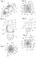
- the male connector 2 of the connector 1 according to the invention shown here as an example is a cable connector in this example and in Fig.1 in a perspective and in Fig.2 shown in a side view.
- Fig.3 shows a view in the direction of the insertion extension 4 of this male connector 2.
- the corresponding female connector 3 is designed as a so-called chassis socket or as a so-called chassis plug, which is intended to be attached to the housing of an electrical device.
- a female connector 3 according to the invention like the male connector 2 shown here, could also be designed as a cable plug, without this requiring any changes to the components essential to the invention. This also applies vice versa for the male connector 2.
- the female connector 3 shown here can be screwed or otherwise fastened to the housing of the electrical device in a manner known per se by means of the fastening holes 36 in the flange 33.
- Fig.4 shows a perspective view of this female connector 3
- Fig.5 a side view.
- Fig.6 shows a view into the insertion extension receptacle interior 11 of this female connector 3 or its insertion extension receptacle 8.
- the male connector 2 has, as is known per se, a housing 29 over which the plug-in extension 4 protrudes.
- the cable grommet 31 On the side opposite the plug-in extension 4 is the cable grommet 31, through which an electrical cable can be inserted into the male connector 2 in a manner known per se and can be contacted there with the electrical contacts 6 of the plug-in extension 4 or male connector 2.
- a slider 30 on the outside of the housing 29 of the male connector 2 there is also a slider 30 known per se, which is intended for releasing a lock designed as in the prior art.
- the housing 29, the cable grommet 31 and the slider 30 are ultimately not relevant to the invention and can be designed as is known per se in the prior art, just like the interior of the housing 29 and the cable grommet 31.
- the plug-in extension 4 has a plug-in extension casing wall 5 which, in the embodiment shown, apart from the projections 12 arranged thereon and projecting outwards, is designed in the shape of a circular cylinder casing, i.e. in particular has an outer surface 25 in the shape of a circular cylinder casing. In the embodiment shown, a total of 4 projections 12 are arranged on this outer surface 25, projecting outwards. These four projections 12 differ in their shape and also in their position. As already stated at the beginning, there can also be more or fewer and differently shaped and also differently arranged projections 12.
- Corresponding receiving slots 13 could just as well be located in the plug-in extension casing wall 5 if the corresponding projections 12 were formed in the plug-in extension receiving casing wall 9 of the plug-in extension 4 of the female connector 3.
- Mixed forms in which both projections 12 and receiving slots 13 are arranged on both the insertion extension casing wall 5 and the insertion extension receiving casing wall 9 are also conceivable.
- the plug-in extension casing wall 5 surrounds the plug-in extension interior space 7 in which the electrical contacts 6 are located.
- the plug-in extension casing wall 5 is, as in the embodiment shown here, advantageously designed to be long enough that the electrical contacts 6 are completely recessed in the plug-in extension interior space 7 and do not protrude above it.
- the countersunk electrical contacts 6 can be clearly seen. It can also be seen that in this embodiment they are arranged on a common circular path 23.
- the molded part 15 with its outward-facing stop surfaces 17 is arranged centrally in the plug-in extension interior 7.
- the shape and function of this molded part 15 and in particular its interaction with the counter-molded part 16 of the female connector 3 will be explained in more detail below.
- the centrally arranged molded part 15 lies here on the longitudinal center axis 19 of the plug-in extension 4 and between the electrical contacts 6.
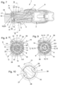
- the plug-in extension receiving casing wall 9 of the plug-in extension receiving 8 surrounds the plug-in extension receiving interior 11 in which the electrical counter-contacts 10 are arranged.
- these electrical counter-contacts 10 are also all arranged on a common circular path 24 and are recessed in the plug-in extension receiving interior 11.
- the external contacts 34 which are in conductive connection with the electrical counter-contacts 10, are used to connect cables or the like and protrude at the rear, i.e. on the side facing away from the flange 33, over the housing 32 of the female connector 3.
- the counter-molded part 16 according to the invention with its two counter-stop surfaces 18, the two free spaces 27 and the rotation stops 28 is also arranged centrally in the plug-in extension receiving interior 11.
- the longitudinal center axis 20 of the insertion extension holder 8 also runs through the counter-molded part 16.
- the insertion extension holder casing wall 9 has a circular-cylindrical inner surface 26, which in this embodiment is penetrated by the receiving slots 13.
- Each receiving slot 13 is followed by a receiving channel 22, which is also arranged in the insertion extension holder casing wall 9 and penetrates the inner surface 26.
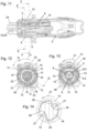
- the male connector 2 with its insertion extension 4 is inserted in the insertion direction 14 starting from the clear insertion position specified by the projections 12 and the corresponding receiving slots 13 in the plug-in extension holder 8 is inserted.
- the plug-in extension 4 is inserted sufficiently far into the plug-in extension holder 8 in the insertion direction 14, the fully inserted position can be reached, in which the electrical contacts 6 in this embodiment are not yet electrically connected or contacted with the electrical counter-contacts 10.
- the plug-in extension 4 In order to reach the end position in which this is the case, the plug-in extension 4 must first be rotated in the circumferential direction 21 starting from the fully inserted position, only then does an electrical contact between the electrical contacts 6 and the electrical counter-contacts 10 occur in this embodiment.
- a seal 35 known per se is located in the insertion extension receiving space 8 of the female connector 3. The front end of the insertion extension casing wall 5 is pressed against this seal 35 in the fully inserted position.
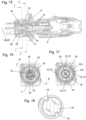
- the insertion extension 4 or the entire male connector 2 is moved from the fully inserted position according to the Fig. 7 to 10 in the circumferential direction 21.
- the projections 12 of the insertion extension are guided in the receiving channels 22 of the insertion extension receiving casing wall 9.
- the electrical contacts 6 are then electrically conductive with the electrical counter contacts 10 connected, as is particularly evident in the Figs. 11 and 13 can be seen.
- the Fig. 11 to 14 In the end position shown, the electrical contacts 6 are then electrically conductive with the electrical counter contacts 10 connected, as is particularly evident in the Figs. 11 and 13 can be seen.
Landscapes
- Physics & Mathematics (AREA)
- General Physics & Mathematics (AREA)
- Optics & Photonics (AREA)
- Details Of Connecting Devices For Male And Female Coupling (AREA)
- Connector Housings Or Holding Contact Members (AREA)
Applications Claiming Priority (3)
| Application Number | Priority Date | Filing Date | Title |
|---|---|---|---|
| DE102018101431.7A DE102018101431A1 (de) | 2018-01-23 | 2018-01-23 | Steckverbindung |
| EP19216920.9A EP3641070A1 (de) | 2018-01-23 | 2018-11-27 | Steckverbindung |
| EP18208607.4A EP3514892B1 (de) | 2018-01-23 | 2018-11-27 | Steckverbindung |
Related Parent Applications (2)
| Application Number | Title | Priority Date | Filing Date |
|---|---|---|---|
| EP18208607.4A Division EP3514892B1 (de) | 2018-01-23 | 2018-11-27 | Steckverbindung |
| EP19216920.9A Division EP3641070A1 (de) | 2018-01-23 | 2018-11-27 | Steckverbindung |
Publications (2)
| Publication Number | Publication Date |
|---|---|
| EP3787128A1 EP3787128A1 (de) | 2021-03-03 |
| EP3787128B1 true EP3787128B1 (de) | 2024-07-17 |
Family
ID=64500270
Family Applications (3)
| Application Number | Title | Priority Date | Filing Date |
|---|---|---|---|
| EP20202736.3A Active EP3787128B1 (de) | 2018-01-23 | 2018-11-27 | Steckverbindung |
| EP18208607.4A Active EP3514892B1 (de) | 2018-01-23 | 2018-11-27 | Steckverbindung |
| EP19216920.9A Withdrawn EP3641070A1 (de) | 2018-01-23 | 2018-11-27 | Steckverbindung |
Family Applications After (2)
| Application Number | Title | Priority Date | Filing Date |
|---|---|---|---|
| EP18208607.4A Active EP3514892B1 (de) | 2018-01-23 | 2018-11-27 | Steckverbindung |
| EP19216920.9A Withdrawn EP3641070A1 (de) | 2018-01-23 | 2018-11-27 | Steckverbindung |
Country Status (5)
| Country | Link |
|---|---|
| US (2) | US10823914B2 (enExample) |
| EP (3) | EP3787128B1 (enExample) |
| JP (2) | JP6705027B2 (enExample) |
| CN (2) | CN110071397B (enExample) |
| DE (1) | DE102018101431A1 (enExample) |
Families Citing this family (4)
| Publication number | Priority date | Publication date | Assignee | Title |
|---|---|---|---|---|
| US10615530B2 (en) | 2017-06-06 | 2020-04-07 | Amphenol Corporation | Spring loaded electrical connector |
| DE102018101431A1 (de) * | 2018-01-23 | 2019-07-25 | Neutrik Ag | Steckverbindung |
| CN113097790B (zh) * | 2021-04-08 | 2022-10-21 | 山东聚辰电缆有限公司 | 一种电力电缆接头及电力电缆接头的连接工艺 |
| EP4533603A1 (de) | 2022-06-02 | 2025-04-09 | Neutrik AG | Einbausteckverbinder |
Family Cites Families (43)
| Publication number | Priority date | Publication date | Assignee | Title |
|---|---|---|---|---|
| US2986612A (en) * | 1959-04-06 | 1961-05-30 | Hubbell Inc Harvey | Electrical connectors for industrial uses |
| US3351887A (en) * | 1965-06-28 | 1967-11-07 | Eldon D Jones | Interlocking electrical connection |
| US3339039A (en) * | 1965-09-10 | 1967-08-29 | Arrow Hart & Hegeman Electric | Electrical connector with contactprotecting and arc-quenching shield |
| AT313404B (de) * | 1970-03-31 | 1974-02-25 | Staff & Schwarz Gmbh | Elektrische Kupplung zum Verbinden elektrischer Leitungen |
| JPH0229176U (enExample) * | 1988-08-18 | 1990-02-26 | ||
| JP2779104B2 (ja) | 1992-11-12 | 1998-07-23 | 日本原子力研究所 | 簡易着脱電気コネクター |
| DE19851301C2 (de) * | 1998-11-06 | 2001-05-17 | Framatome Connectors Int | Elektrischer Steckverbinder für Zünder |
| JP2000208209A (ja) | 1999-01-14 | 2000-07-28 | D D K Ltd | 電源接続用コネクタ |
| US6394661B1 (en) * | 1999-02-09 | 2002-05-28 | Fiber Systems International | Fiber optic connector having receptacle housing for radially aligning mating inserts |
| US6234683B1 (en) * | 1999-09-13 | 2001-05-22 | Stratos Lightwave, Inc. | Field repairable hermaphroditic connector |
| US6394856B1 (en) * | 2000-01-04 | 2002-05-28 | Tyco Electronics Corp. | Electrical connector with programmable keying |
| US6986686B2 (en) * | 2001-02-23 | 2006-01-17 | Olympus Corporation | Electrical plug for supplying electric power from a power supply to a medical instrument |
| US6764351B2 (en) * | 2001-08-27 | 2004-07-20 | Campagnie Deutsch GmbH | Electrical connector |
| US7429170B2 (en) * | 2005-10-31 | 2008-09-30 | Owens-Illinois Closure Inc. | Method and machine for compression molding closure shells |
| DE102006001630A1 (de) * | 2006-01-11 | 2007-07-12 | Neutrik Aktiengesellschaft | Steckerbuchse |
| JP4557915B2 (ja) | 2006-03-24 | 2010-10-06 | 株式会社七星科学研究所 | シャッター付き電気コネクタ |
| JP4777148B2 (ja) | 2006-05-31 | 2011-09-21 | 矢崎総業株式会社 | コネクタ |
| US20100136808A1 (en) * | 2007-03-27 | 2010-06-03 | Van-System S.R.L. | Electrical Connector |
| US7585116B2 (en) * | 2007-04-12 | 2009-09-08 | Fiber Systems International | Fiber optic connector having hermaphroditic coupling mechanism |
| US7435112B1 (en) * | 2008-02-08 | 2008-10-14 | Tyco Electronics Corporation | Electrical connector having a mechanical mating cycle limitation |
| JP5341532B2 (ja) * | 2009-01-19 | 2013-11-13 | 第一電子工業株式会社 | 1対の誤嵌合防止キー及び該キーを用いた電気コネクタ |
| JP4847564B2 (ja) * | 2009-07-22 | 2011-12-28 | 日本航空電子工業株式会社 | コネクタ組立体 |
| JP4925372B2 (ja) * | 2009-12-28 | 2012-04-25 | 日本航空電子工業株式会社 | 光コネクタアダプタ |
| US8550843B2 (en) * | 2010-11-22 | 2013-10-08 | Andrew Llc | Tabbed connector interface |
| JP5775335B2 (ja) | 2011-03-16 | 2015-09-09 | 矢崎総業株式会社 | 突き当てコネクタ |
| DE102011113062A1 (de) * | 2011-09-09 | 2013-03-14 | Amphenol-Tuchel Electronics Gmbh | Kontaktgeschützter Steckverbinder |
| KR101796427B1 (ko) * | 2012-06-26 | 2017-11-09 | 후아웨이 테크놀러지 컴퍼니 리미티드 | 광 섬유 조인트, 광 섬유 어댑터, 및 광 섬유 커넥터 |
| JP5946377B2 (ja) * | 2012-09-07 | 2016-07-06 | 矢崎総業株式会社 | コネクタ |
| US9252539B2 (en) * | 2012-11-02 | 2016-02-02 | Hubbell Incorporated | Internally switched female receptacle or connector with plug-latching safety interlock |
| DE202013006297U1 (de) | 2013-07-11 | 2013-07-25 | Rosenberger Hochfrequenztechnik Gmbh & Co. Kg | Steckverbinder |
| WO2016095213A1 (en) * | 2014-12-19 | 2016-06-23 | Tyco Electronics (Shanghai) Co., Ltd. | Hardened fiber optic connector with pre-compressed spring |
| US9755382B2 (en) * | 2015-03-13 | 2017-09-05 | Senko Advanced Components, Inc. | Connector system with interchangeable connector modules for optical fibers, electrical conductors, or both |
| USD779434S1 (en) * | 2015-04-09 | 2017-02-21 | Neutrik Ag | Electrical connector |
| DE202015003177U1 (de) | 2015-04-30 | 2015-05-13 | Rosenberger Hochfrequenztechnik Gmbh & Co. Kg | Steckverbindung und Satz von Steckverbindungen |
| WO2017106514A1 (en) * | 2015-12-16 | 2017-06-22 | Commscope Technologies Llc | Field installed fiber optic connector |
| US9905956B2 (en) * | 2015-12-22 | 2018-02-27 | Biosense Webster (Israel) Ltd. | Preventing unwanted contact between terminals |
| US10128594B2 (en) * | 2015-12-22 | 2018-11-13 | Biosense Webster (Israel) Ltd. | Connectors having three-dimensional surfaces |
| DE102016101255A1 (de) * | 2016-01-25 | 2017-07-27 | Neutrik Ag | Verbinder |
| JP2018081144A (ja) * | 2016-11-14 | 2018-05-24 | 住友電気工業株式会社 | 光コネクタ |
| JP2019000797A (ja) * | 2017-06-14 | 2019-01-10 | 大日本印刷株式会社 | ウェブクリーナーおよびウェブクリーナーシステム |
| FR3076955B1 (fr) * | 2018-01-12 | 2020-01-31 | Marechal Electric | Socle de prise equipe d'un disque et d'un obturateur |
| DE102018101431A1 (de) * | 2018-01-23 | 2019-07-25 | Neutrik Ag | Steckverbindung |
| GB2594946B (en) * | 2020-05-12 | 2025-01-22 | Gyrus Medical Ltd | RF Shaver connector |
-
2018
- 2018-01-23 DE DE102018101431.7A patent/DE102018101431A1/de not_active Withdrawn
- 2018-11-27 EP EP20202736.3A patent/EP3787128B1/de active Active
- 2018-11-27 EP EP18208607.4A patent/EP3514892B1/de active Active
- 2018-11-27 EP EP19216920.9A patent/EP3641070A1/de not_active Withdrawn
-
2019
- 2019-01-07 JP JP2019000797A patent/JP6705027B2/ja active Active
- 2019-01-11 US US16/245,751 patent/US10823914B2/en active Active
- 2019-01-23 CN CN201910063569.5A patent/CN110071397B/zh active Active
- 2019-01-23 CN CN202110187223.3A patent/CN112886338B/zh active Active
-
2020
- 2020-05-12 JP JP2020084081A patent/JP7333286B2/ja active Active
- 2020-10-13 US US17/068,968 patent/US11409050B2/en active Active
Also Published As
| Publication number | Publication date |
|---|---|
| US20190227239A1 (en) | 2019-07-25 |
| EP3514892A1 (de) | 2019-07-24 |
| DE102018101431A1 (de) | 2019-07-25 |
| EP3641070A1 (de) | 2020-04-22 |
| EP3787128A1 (de) | 2021-03-03 |
| CN110071397B (zh) | 2021-02-05 |
| JP2019129148A (ja) | 2019-08-01 |
| JP7333286B2 (ja) | 2023-08-24 |
| JP2020181818A (ja) | 2020-11-05 |
| CN112886338A (zh) | 2021-06-01 |
| US11409050B2 (en) | 2022-08-09 |
| EP3514892B1 (de) | 2020-05-20 |
| JP6705027B2 (ja) | 2020-06-03 |
| US10823914B2 (en) | 2020-11-03 |
| CN112886338B (zh) | 2023-05-09 |
| US20210026079A1 (en) | 2021-01-28 |
| CN110071397A (zh) | 2019-07-30 |
Similar Documents
| Publication | Publication Date | Title |
|---|---|---|
| DE102006016882B4 (de) | Steckverbinder | |
| EP1730815B1 (de) | Koaxialsteckverbindung für leiterplatten mit gefedertem toleranzausgleich | |
| EP3031103B1 (de) | System aus mehreren elektrischen steckverbindermodulen und einem elektrisch leitfähigen halterahmen | |
| EP3057183B1 (de) | Gedichteter Stecker | |
| EP3516741B1 (de) | Stecker mit schutz | |
| EP3787128B1 (de) | Steckverbindung | |
| DE102015015202B4 (de) | Steckverbinder und Stecksystem | |
| EP3176885B1 (de) | Steckerverbinderanordnung | |
| EP2862237B1 (de) | Isolierkörper eines steckverbinders | |
| DE102015201089A1 (de) | Zwischengehäuse mit einer CPA-Aufnahme und Steckverbindersysteme umfassend ein solches | |
| DE102014103864A1 (de) | Steckvorrichtungsmontage in Elektrofahrzeugen | |
| EP3713018B1 (de) | Elektrischer steckverbinder | |
| DE2215757A1 (de) | Koaxialsteckverbindung | |
| EP3386033A1 (de) | Isolierkörper für eine steckverbindereinheit | |
| EP4010949B1 (de) | Elektrischer steckverbinder | |
| EP3170230B1 (de) | Modulares gehäuseabgangssystem | |
| DE102017222809B4 (de) | Elektrischer Steckverbinder und Steckverbindung | |
| DE102018122848A1 (de) | Modulelement zur Aufnahme in einem Halterahmen für einen Steckverbinder | |
| EP1867024B1 (de) | Leitungsdurchführungsvorrichtung | |
| DE102013113878A1 (de) | Steckverbinder mit Einzeladerabdichtung | |
| EP1381118B1 (de) | Symmetrischer Steckverbinder | |
| DE202012101303U1 (de) | Steckverbindergehäuse | |
| EP1632009A1 (de) | Kontaktelement und komplementäre leitungskammer für einen stecker oder eine buchse in schneidklemmtechnik | |
| DE102020109823A1 (de) | Entladestecker für einen Akku eines Elektrofahrrades | |
| DE102021107137B4 (de) | Elektrischer Anschlussverbinder und elektrische Steckverbinderanordnung hierfür |
Legal Events
| Date | Code | Title | Description |
|---|---|---|---|
| PUAI | Public reference made under article 153(3) epc to a published international application that has entered the european phase |
Free format text: ORIGINAL CODE: 0009012 |
|
| STAA | Information on the status of an ep patent application or granted ep patent |
Free format text: STATUS: THE APPLICATION HAS BEEN PUBLISHED |
|
| AC | Divisional application: reference to earlier application |
Ref document number: 3514892 Country of ref document: EP Kind code of ref document: P Ref document number: 3641070 Country of ref document: EP Kind code of ref document: P |
|
| AK | Designated contracting states |
Kind code of ref document: A1 Designated state(s): AL AT BE BG CH CY CZ DE DK EE ES FI FR GB GR HR HU IE IS IT LI LT LU LV MC MK MT NL NO PL PT RO RS SE SI SK SM TR |
|
| AX | Request for extension of the european patent |
Extension state: BA ME |
|
| STAA | Information on the status of an ep patent application or granted ep patent |
Free format text: STATUS: REQUEST FOR EXAMINATION WAS MADE |
|
| 17P | Request for examination filed |
Effective date: 20210809 |
|
| RBV | Designated contracting states (corrected) |
Designated state(s): AL AT BE BG CH CY CZ DE DK EE ES FI FR GB GR HR HU IE IS IT LI LT LU LV MC MK MT NL NO PL PT RO RS SE SI SK SM TR |
|
| STAA | Information on the status of an ep patent application or granted ep patent |
Free format text: STATUS: EXAMINATION IS IN PROGRESS |
|
| 17Q | First examination report despatched |
Effective date: 20220614 |
|
| GRAP | Despatch of communication of intention to grant a patent |
Free format text: ORIGINAL CODE: EPIDOSNIGR1 |
|
| STAA | Information on the status of an ep patent application or granted ep patent |
Free format text: STATUS: GRANT OF PATENT IS INTENDED |
|
| RIC1 | Information provided on ipc code assigned before grant |
Ipc: H01R 13/625 20060101ALN20240320BHEP Ipc: H01R 13/71 20060101ALN20240320BHEP Ipc: H01R 13/64 20060101AFI20240320BHEP |
|
| INTG | Intention to grant announced |
Effective date: 20240408 |
|
| GRAS | Grant fee paid |
Free format text: ORIGINAL CODE: EPIDOSNIGR3 |
|
| GRAA | (expected) grant |
Free format text: ORIGINAL CODE: 0009210 |
|
| STAA | Information on the status of an ep patent application or granted ep patent |
Free format text: STATUS: THE PATENT HAS BEEN GRANTED |
|
| AC | Divisional application: reference to earlier application |
Ref document number: 3514892 Country of ref document: EP Kind code of ref document: P Ref document number: 3641070 Country of ref document: EP Kind code of ref document: P |
|
| AK | Designated contracting states |
Kind code of ref document: B1 Designated state(s): AL AT BE BG CH CY CZ DE DK EE ES FI FR GB GR HR HU IE IS IT LI LT LU LV MC MK MT NL NO PL PT RO RS SE SI SK SM TR |
|
| REG | Reference to a national code |
Ref country code: CH Ref legal event code: EP |
|
| REG | Reference to a national code |
Ref country code: DE Ref legal event code: R096 Ref document number: 502018014882 Country of ref document: DE |
|
| REG | Reference to a national code |
Ref country code: IE Ref legal event code: FG4D Free format text: LANGUAGE OF EP DOCUMENT: GERMAN |
|
| REG | Reference to a national code |
Ref country code: LT Ref legal event code: MG9D |
|
| REG | Reference to a national code |
Ref country code: NL Ref legal event code: MP Effective date: 20240717 |
|
| PG25 | Lapsed in a contracting state [announced via postgrant information from national office to epo] |
Ref country code: PT Free format text: LAPSE BECAUSE OF FAILURE TO SUBMIT A TRANSLATION OF THE DESCRIPTION OR TO PAY THE FEE WITHIN THE PRESCRIBED TIME-LIMIT Effective date: 20241118 |
|
| PG25 | Lapsed in a contracting state [announced via postgrant information from national office to epo] |
Ref country code: NL Free format text: LAPSE BECAUSE OF FAILURE TO SUBMIT A TRANSLATION OF THE DESCRIPTION OR TO PAY THE FEE WITHIN THE PRESCRIBED TIME-LIMIT Effective date: 20240717 |
|
| PG25 | Lapsed in a contracting state [announced via postgrant information from national office to epo] |
Ref country code: PT Free format text: LAPSE BECAUSE OF FAILURE TO SUBMIT A TRANSLATION OF THE DESCRIPTION OR TO PAY THE FEE WITHIN THE PRESCRIBED TIME-LIMIT Effective date: 20241118 Ref country code: NL Free format text: LAPSE BECAUSE OF FAILURE TO SUBMIT A TRANSLATION OF THE DESCRIPTION OR TO PAY THE FEE WITHIN THE PRESCRIBED TIME-LIMIT Effective date: 20240717 |
|
| PGFP | Annual fee paid to national office [announced via postgrant information from national office to epo] |
Ref country code: DE Payment date: 20241121 Year of fee payment: 7 |
|
| PG25 | Lapsed in a contracting state [announced via postgrant information from national office to epo] |
Ref country code: NO Free format text: LAPSE BECAUSE OF FAILURE TO SUBMIT A TRANSLATION OF THE DESCRIPTION OR TO PAY THE FEE WITHIN THE PRESCRIBED TIME-LIMIT Effective date: 20241017 |
|
| PG25 | Lapsed in a contracting state [announced via postgrant information from national office to epo] |
Ref country code: GR Free format text: LAPSE BECAUSE OF FAILURE TO SUBMIT A TRANSLATION OF THE DESCRIPTION OR TO PAY THE FEE WITHIN THE PRESCRIBED TIME-LIMIT Effective date: 20241018 Ref country code: FI Free format text: LAPSE BECAUSE OF FAILURE TO SUBMIT A TRANSLATION OF THE DESCRIPTION OR TO PAY THE FEE WITHIN THE PRESCRIBED TIME-LIMIT Effective date: 20240717 Ref country code: PL Free format text: LAPSE BECAUSE OF FAILURE TO SUBMIT A TRANSLATION OF THE DESCRIPTION OR TO PAY THE FEE WITHIN THE PRESCRIBED TIME-LIMIT Effective date: 20240717 |
|
| PG25 | Lapsed in a contracting state [announced via postgrant information from national office to epo] |
Ref country code: BG Free format text: LAPSE BECAUSE OF FAILURE TO SUBMIT A TRANSLATION OF THE DESCRIPTION OR TO PAY THE FEE WITHIN THE PRESCRIBED TIME-LIMIT Effective date: 20240717 |
|
| PG25 | Lapsed in a contracting state [announced via postgrant information from national office to epo] |
Ref country code: LV Free format text: LAPSE BECAUSE OF FAILURE TO SUBMIT A TRANSLATION OF THE DESCRIPTION OR TO PAY THE FEE WITHIN THE PRESCRIBED TIME-LIMIT Effective date: 20240717 |
|
| PG25 | Lapsed in a contracting state [announced via postgrant information from national office to epo] |
Ref country code: IS Free format text: LAPSE BECAUSE OF FAILURE TO SUBMIT A TRANSLATION OF THE DESCRIPTION OR TO PAY THE FEE WITHIN THE PRESCRIBED TIME-LIMIT Effective date: 20241117 |
|
| PG25 | Lapsed in a contracting state [announced via postgrant information from national office to epo] |
Ref country code: HR Free format text: LAPSE BECAUSE OF FAILURE TO SUBMIT A TRANSLATION OF THE DESCRIPTION OR TO PAY THE FEE WITHIN THE PRESCRIBED TIME-LIMIT Effective date: 20240717 |
|
| PG25 | Lapsed in a contracting state [announced via postgrant information from national office to epo] |
Ref country code: RS Free format text: LAPSE BECAUSE OF FAILURE TO SUBMIT A TRANSLATION OF THE DESCRIPTION OR TO PAY THE FEE WITHIN THE PRESCRIBED TIME-LIMIT Effective date: 20241017 Ref country code: ES Free format text: LAPSE BECAUSE OF FAILURE TO SUBMIT A TRANSLATION OF THE DESCRIPTION OR TO PAY THE FEE WITHIN THE PRESCRIBED TIME-LIMIT Effective date: 20240717 |
|
| PG25 | Lapsed in a contracting state [announced via postgrant information from national office to epo] |
Ref country code: RS Free format text: LAPSE BECAUSE OF FAILURE TO SUBMIT A TRANSLATION OF THE DESCRIPTION OR TO PAY THE FEE WITHIN THE PRESCRIBED TIME-LIMIT Effective date: 20241017 Ref country code: PL Free format text: LAPSE BECAUSE OF FAILURE TO SUBMIT A TRANSLATION OF THE DESCRIPTION OR TO PAY THE FEE WITHIN THE PRESCRIBED TIME-LIMIT Effective date: 20240717 Ref country code: NO Free format text: LAPSE BECAUSE OF FAILURE TO SUBMIT A TRANSLATION OF THE DESCRIPTION OR TO PAY THE FEE WITHIN THE PRESCRIBED TIME-LIMIT Effective date: 20241017 Ref country code: LV Free format text: LAPSE BECAUSE OF FAILURE TO SUBMIT A TRANSLATION OF THE DESCRIPTION OR TO PAY THE FEE WITHIN THE PRESCRIBED TIME-LIMIT Effective date: 20240717 Ref country code: IS Free format text: LAPSE BECAUSE OF FAILURE TO SUBMIT A TRANSLATION OF THE DESCRIPTION OR TO PAY THE FEE WITHIN THE PRESCRIBED TIME-LIMIT Effective date: 20241117 Ref country code: HR Free format text: LAPSE BECAUSE OF FAILURE TO SUBMIT A TRANSLATION OF THE DESCRIPTION OR TO PAY THE FEE WITHIN THE PRESCRIBED TIME-LIMIT Effective date: 20240717 Ref country code: GR Free format text: LAPSE BECAUSE OF FAILURE TO SUBMIT A TRANSLATION OF THE DESCRIPTION OR TO PAY THE FEE WITHIN THE PRESCRIBED TIME-LIMIT Effective date: 20241018 Ref country code: FI Free format text: LAPSE BECAUSE OF FAILURE TO SUBMIT A TRANSLATION OF THE DESCRIPTION OR TO PAY THE FEE WITHIN THE PRESCRIBED TIME-LIMIT Effective date: 20240717 Ref country code: ES Free format text: LAPSE BECAUSE OF FAILURE TO SUBMIT A TRANSLATION OF THE DESCRIPTION OR TO PAY THE FEE WITHIN THE PRESCRIBED TIME-LIMIT Effective date: 20240717 Ref country code: BG Free format text: LAPSE BECAUSE OF FAILURE TO SUBMIT A TRANSLATION OF THE DESCRIPTION OR TO PAY THE FEE WITHIN THE PRESCRIBED TIME-LIMIT Effective date: 20240717 |
|
| PG25 | Lapsed in a contracting state [announced via postgrant information from national office to epo] |
Ref country code: SM Free format text: LAPSE BECAUSE OF FAILURE TO SUBMIT A TRANSLATION OF THE DESCRIPTION OR TO PAY THE FEE WITHIN THE PRESCRIBED TIME-LIMIT Effective date: 20240717 Ref country code: RO Free format text: LAPSE BECAUSE OF FAILURE TO SUBMIT A TRANSLATION OF THE DESCRIPTION OR TO PAY THE FEE WITHIN THE PRESCRIBED TIME-LIMIT Effective date: 20240717 Ref country code: DK Free format text: LAPSE BECAUSE OF FAILURE TO SUBMIT A TRANSLATION OF THE DESCRIPTION OR TO PAY THE FEE WITHIN THE PRESCRIBED TIME-LIMIT Effective date: 20240717 |
|
| REG | Reference to a national code |
Ref country code: DE Ref legal event code: R097 Ref document number: 502018014882 Country of ref document: DE |
|
| PG25 | Lapsed in a contracting state [announced via postgrant information from national office to epo] |
Ref country code: EE Free format text: LAPSE BECAUSE OF FAILURE TO SUBMIT A TRANSLATION OF THE DESCRIPTION OR TO PAY THE FEE WITHIN THE PRESCRIBED TIME-LIMIT Effective date: 20240717 |
|
| PG25 | Lapsed in a contracting state [announced via postgrant information from national office to epo] |
Ref country code: CZ Free format text: LAPSE BECAUSE OF FAILURE TO SUBMIT A TRANSLATION OF THE DESCRIPTION OR TO PAY THE FEE WITHIN THE PRESCRIBED TIME-LIMIT Effective date: 20240717 |
|
| PG25 | Lapsed in a contracting state [announced via postgrant information from national office to epo] |
Ref country code: SK Free format text: LAPSE BECAUSE OF FAILURE TO SUBMIT A TRANSLATION OF THE DESCRIPTION OR TO PAY THE FEE WITHIN THE PRESCRIBED TIME-LIMIT Effective date: 20240717 |
|
| PLBE | No opposition filed within time limit |
Free format text: ORIGINAL CODE: 0009261 |
|
| STAA | Information on the status of an ep patent application or granted ep patent |
Free format text: STATUS: NO OPPOSITION FILED WITHIN TIME LIMIT |
|
| 26N | No opposition filed |
Effective date: 20250422 |
|
| REG | Reference to a national code |
Ref country code: CH Ref legal event code: PL |
|
| PG25 | Lapsed in a contracting state [announced via postgrant information from national office to epo] |
Ref country code: MC Free format text: LAPSE BECAUSE OF FAILURE TO SUBMIT A TRANSLATION OF THE DESCRIPTION OR TO PAY THE FEE WITHIN THE PRESCRIBED TIME-LIMIT Effective date: 20240717 |
|
| PG25 | Lapsed in a contracting state [announced via postgrant information from national office to epo] |
Ref country code: LU Free format text: LAPSE BECAUSE OF NON-PAYMENT OF DUE FEES Effective date: 20241127 |
|
| REG | Reference to a national code |
Ref country code: CH Ref legal event code: PL |
|
| GBPC | Gb: european patent ceased through non-payment of renewal fee |
Effective date: 20241127 |
|
| PG25 | Lapsed in a contracting state [announced via postgrant information from national office to epo] |
Ref country code: CH Free format text: LAPSE BECAUSE OF NON-PAYMENT OF DUE FEES Effective date: 20241130 |
|
| REG | Reference to a national code |
Ref country code: BE Ref legal event code: MM Effective date: 20241130 |
|
| PG25 | Lapsed in a contracting state [announced via postgrant information from national office to epo] |
Ref country code: SE Free format text: LAPSE BECAUSE OF FAILURE TO SUBMIT A TRANSLATION OF THE DESCRIPTION OR TO PAY THE FEE WITHIN THE PRESCRIBED TIME-LIMIT Effective date: 20240717 |
|
| PG25 | Lapsed in a contracting state [announced via postgrant information from national office to epo] |
Ref country code: BE Free format text: LAPSE BECAUSE OF NON-PAYMENT OF DUE FEES Effective date: 20241130 Ref country code: GB Free format text: LAPSE BECAUSE OF NON-PAYMENT OF DUE FEES Effective date: 20241127 |
|
| PG25 | Lapsed in a contracting state [announced via postgrant information from national office to epo] |
Ref country code: FR Free format text: LAPSE BECAUSE OF NON-PAYMENT OF DUE FEES Effective date: 20241130 |
|
| PG25 | Lapsed in a contracting state [announced via postgrant information from national office to epo] |
Ref country code: IE Free format text: LAPSE BECAUSE OF NON-PAYMENT OF DUE FEES Effective date: 20241127 |