EP3786941B1 - Musikinstrumentensteuergerät und elektronisches musikinstrumentensystem - Google Patents
Musikinstrumentensteuergerät und elektronisches musikinstrumentensystem Download PDFInfo
- Publication number
- EP3786941B1 EP3786941B1 EP18916925.3A EP18916925A EP3786941B1 EP 3786941 B1 EP3786941 B1 EP 3786941B1 EP 18916925 A EP18916925 A EP 18916925A EP 3786941 B1 EP3786941 B1 EP 3786941B1
- Authority
- EP
- European Patent Office
- Prior art keywords
- signal
- sensor
- musical instrument
- amount
- sound
- Prior art date
- Legal status (The legal status is an assumption and is not a legal conclusion. Google has not performed a legal analysis and makes no representation as to the accuracy of the status listed.)
- Active
Links
Images





Classifications
-
- G—PHYSICS
- G10—MUSICAL INSTRUMENTS; ACOUSTICS
- G10H—ELECTROPHONIC MUSICAL INSTRUMENTS; INSTRUMENTS IN WHICH THE TONES ARE GENERATED BY ELECTROMECHANICAL MEANS OR ELECTRONIC GENERATORS, OR IN WHICH THE TONES ARE SYNTHESISED FROM A DATA STORE
- G10H1/00—Details of electrophonic musical instruments
- G10H1/0033—Recording/reproducing or transmission of music for electrophonic musical instruments
- G10H1/0083—Recording/reproducing or transmission of music for electrophonic musical instruments using wireless transmission, e.g. radio, light, infrared
-
- G—PHYSICS
- G10—MUSICAL INSTRUMENTS; ACOUSTICS
- G10H—ELECTROPHONIC MUSICAL INSTRUMENTS; INSTRUMENTS IN WHICH THE TONES ARE GENERATED BY ELECTROMECHANICAL MEANS OR ELECTRONIC GENERATORS, OR IN WHICH THE TONES ARE SYNTHESISED FROM A DATA STORE
- G10H1/00—Details of electrophonic musical instruments
- G10H1/02—Means for controlling the tone frequencies, e.g. attack or decay; Means for producing special musical effects, e.g. vibratos or glissandos
- G10H1/04—Means for controlling the tone frequencies, e.g. attack or decay; Means for producing special musical effects, e.g. vibratos or glissandos by additional modulation
- G10H1/053—Means for controlling the tone frequencies, e.g. attack or decay; Means for producing special musical effects, e.g. vibratos or glissandos by additional modulation during execution only
-
- G—PHYSICS
- G10—MUSICAL INSTRUMENTS; ACOUSTICS
- G10H—ELECTROPHONIC MUSICAL INSTRUMENTS; INSTRUMENTS IN WHICH THE TONES ARE GENERATED BY ELECTROMECHANICAL MEANS OR ELECTRONIC GENERATORS, OR IN WHICH THE TONES ARE SYNTHESISED FROM A DATA STORE
- G10H1/00—Details of electrophonic musical instruments
- G10H1/0008—Associated control or indicating means
-
- G—PHYSICS
- G10—MUSICAL INSTRUMENTS; ACOUSTICS
- G10H—ELECTROPHONIC MUSICAL INSTRUMENTS; INSTRUMENTS IN WHICH THE TONES ARE GENERATED BY ELECTROMECHANICAL MEANS OR ELECTRONIC GENERATORS, OR IN WHICH THE TONES ARE SYNTHESISED FROM A DATA STORE
- G10H1/00—Details of electrophonic musical instruments
- G10H1/0033—Recording/reproducing or transmission of music for electrophonic musical instruments
- G10H1/0041—Recording/reproducing or transmission of music for electrophonic musical instruments in coded form
- G10H1/0058—Transmission between separate instruments or between individual components of a musical system
- G10H1/0066—Transmission between separate instruments or between individual components of a musical system using a MIDI interface
-
- G—PHYSICS
- G10—MUSICAL INSTRUMENTS; ACOUSTICS
- G10H—ELECTROPHONIC MUSICAL INSTRUMENTS; INSTRUMENTS IN WHICH THE TONES ARE GENERATED BY ELECTROMECHANICAL MEANS OR ELECTRONIC GENERATORS, OR IN WHICH THE TONES ARE SYNTHESISED FROM A DATA STORE
- G10H2210/00—Aspects or methods of musical processing having intrinsic musical character, i.e. involving musical theory or musical parameters or relying on musical knowledge, as applied in electrophonic musical tools or instruments
- G10H2210/155—Musical effects
- G10H2210/195—Modulation effects, i.e. smooth non-discontinuous variations over a time interval, e.g. within a note, melody or musical transition, of any sound parameter, e.g. amplitude, pitch, spectral response or playback speed
- G10H2210/221—Glissando, i.e. pitch smoothly sliding from one note to another, e.g. gliss, glide, slide, bend, smear or sweep
- G10H2210/225—Portamento, i.e. smooth continuously variable pitch-bend, without emphasis of each chromatic pitch during the pitch change, which only stops at the end of the pitch shift, as obtained, e.g. by a MIDI pitch wheel or trombone
-
- G—PHYSICS
- G10—MUSICAL INSTRUMENTS; ACOUSTICS
- G10H—ELECTROPHONIC MUSICAL INSTRUMENTS; INSTRUMENTS IN WHICH THE TONES ARE GENERATED BY ELECTROMECHANICAL MEANS OR ELECTRONIC GENERATORS, OR IN WHICH THE TONES ARE SYNTHESISED FROM A DATA STORE
- G10H2210/00—Aspects or methods of musical processing having intrinsic musical character, i.e. involving musical theory or musical parameters or relying on musical knowledge, as applied in electrophonic musical tools or instruments
- G10H2210/325—Musical pitch modification
-
- G—PHYSICS
- G10—MUSICAL INSTRUMENTS; ACOUSTICS
- G10H—ELECTROPHONIC MUSICAL INSTRUMENTS; INSTRUMENTS IN WHICH THE TONES ARE GENERATED BY ELECTROMECHANICAL MEANS OR ELECTRONIC GENERATORS, OR IN WHICH THE TONES ARE SYNTHESISED FROM A DATA STORE
- G10H2220/00—Input/output interfacing specifically adapted for electrophonic musical tools or instruments
- G10H2220/155—User input interfaces for electrophonic musical instruments
- G10H2220/201—User input interfaces for electrophonic musical instruments for movement interpretation, i.e. capturing and recognizing a gesture or a specific kind of movement, e.g. to control a musical instrument
-
- G—PHYSICS
- G10—MUSICAL INSTRUMENTS; ACOUSTICS
- G10H—ELECTROPHONIC MUSICAL INSTRUMENTS; INSTRUMENTS IN WHICH THE TONES ARE GENERATED BY ELECTROMECHANICAL MEANS OR ELECTRONIC GENERATORS, OR IN WHICH THE TONES ARE SYNTHESISED FROM A DATA STORE
- G10H2220/00—Input/output interfacing specifically adapted for electrophonic musical tools or instruments
- G10H2220/155—User input interfaces for electrophonic musical instruments
- G10H2220/321—Garment sensors, i.e. musical control means with trigger surfaces or joint angle sensors, worn as a garment by the player, e.g. bracelet, intelligent clothing
- G10H2220/331—Ring or other finger-attached control device
-
- G—PHYSICS
- G10—MUSICAL INSTRUMENTS; ACOUSTICS
- G10H—ELECTROPHONIC MUSICAL INSTRUMENTS; INSTRUMENTS IN WHICH THE TONES ARE GENERATED BY ELECTROMECHANICAL MEANS OR ELECTRONIC GENERATORS, OR IN WHICH THE TONES ARE SYNTHESISED FROM A DATA STORE
- G10H2220/00—Input/output interfacing specifically adapted for electrophonic musical tools or instruments
- G10H2220/155—User input interfaces for electrophonic musical instruments
- G10H2220/391—Angle sensing for musical purposes, using data from a gyroscope, gyrometer or other angular velocity or angular movement sensing device
-
- G—PHYSICS
- G10—MUSICAL INSTRUMENTS; ACOUSTICS
- G10H—ELECTROPHONIC MUSICAL INSTRUMENTS; INSTRUMENTS IN WHICH THE TONES ARE GENERATED BY ELECTROMECHANICAL MEANS OR ELECTRONIC GENERATORS, OR IN WHICH THE TONES ARE SYNTHESISED FROM A DATA STORE
- G10H2220/00—Input/output interfacing specifically adapted for electrophonic musical tools or instruments
- G10H2220/155—User input interfaces for electrophonic musical instruments
- G10H2220/395—Acceleration sensing or accelerometer use, e.g. 3D movement computation by integration of accelerometer data, angle sensing with respect to the vertical, i.e. gravity sensing
-
- G—PHYSICS
- G10—MUSICAL INSTRUMENTS; ACOUSTICS
- G10H—ELECTROPHONIC MUSICAL INSTRUMENTS; INSTRUMENTS IN WHICH THE TONES ARE GENERATED BY ELECTROMECHANICAL MEANS OR ELECTRONIC GENERATORS, OR IN WHICH THE TONES ARE SYNTHESISED FROM A DATA STORE
- G10H2220/00—Input/output interfacing specifically adapted for electrophonic musical tools or instruments
- G10H2220/155—User input interfaces for electrophonic musical instruments
- G10H2220/401—3D sensing, i.e. three-dimensional (x, y, z) position or movement sensing
-
- G—PHYSICS
- G10—MUSICAL INSTRUMENTS; ACOUSTICS
- G10H—ELECTROPHONIC MUSICAL INSTRUMENTS; INSTRUMENTS IN WHICH THE TONES ARE GENERATED BY ELECTROMECHANICAL MEANS OR ELECTRONIC GENERATORS, OR IN WHICH THE TONES ARE SYNTHESISED FROM A DATA STORE
- G10H2240/00—Data organisation or data communication aspects, specifically adapted for electrophonic musical tools or instruments
- G10H2240/171—Transmission of musical instrument data, control or status information; Transmission, remote access or control of music data for electrophonic musical instruments
- G10H2240/281—Protocol or standard connector for transmission of analog or digital data to or from an electrophonic musical instrument
- G10H2240/321—Bluetooth®
Definitions
- the present disclosure relates to control of an electronic musical instrument.
- a mechanism for allowing a player to adjust musical sound parameters such as pitch bend and expression is widely used.
- musical sound parameters can be changed while carrying out performance using an operator such as a wheel or a lever which is provided in a housing.
- EP 3 039 671 A1 disclose capacitive touch sensing musical controllers using multi-touch control.
- US 5 949 012 A discloses a touch panel for setting after-touch effects of a musical MIDI keyboard.
- US 2011/303076 A1 discloses a musical instrument controlled by sticks fitted with accelerometer sensors. A sound colour of the instrument to be played is controlled based on accelerometer-based angular values detected.
- Patent Literature 1 discloses a controller that detects movement of a player's head and controls musical sound parameters on the basis of the detected movement of the head.
- Patent Literature 1 Japanese Patent Laid-Open No. H3-288897
- the controller has difficulty in being combined with a musical instrument (for example, a keyboard instrument) which is played with movement of fingertips.
- a musical instrument for example, a keyboard instrument
- a posture of a finger pressing a key can change at every moment, there is concern about change of each musical sound parameter for each emission of sound.
- the present disclosure is made in consideration of the above-mentioned problems and an objective thereof is to provide a musical instrument controller that can accurately perform control of musical sound parameters.
- a musical instrument controller is set out in appended claim 1, and comprise a device that transmits a control signal to a sound generation device that emits sound on the basis of a musical performance signal which is acquired from a musical performance device.
- the sound generation device is a device that processes or generates sound on the basis of the musical performance signal transmitted from the musical performance device.
- the sound generation device may be a sound source or may be an effect adding device such as an effector.
- the musical performance device is a device that outputs a signal (a musical performance signal) based on the musical performance operation to the sound generation device.
- the sound generation device is a sound source
- the musical performance signal may be a sound emission start signal or a sound emission stop signal.
- the musical performance signal may be a sound signal.
- a musical instrument controller is a device that transmits a control signal to a sound generation device.
- a control signal is typically a signal for controlling a sound-emitting state such as a signal for designating pitch bend or expression.
- the present disclosure can be applied to a system that performs a musical performance operation using a musical performance device and controls a sound-emitting state of musical sound using a controller.
- a musical instrument controller includes: a reception means that receives a sound emission start signal which is transmitted on the basis of a musical performance operation from a musical performance device; a sensor that detects an amount of displacement from a reference position; and a control means that generates a control signal on the basis of the amount of displacement from the reference position and transmits the control signal to a sound generation device.
- the control means sets the reference position on the basis of the sound emission start signal which is received from the musical performance device.
- the sensor is a sensor that detects an amount of displacement from a reference position.
- the control means generates a control signal based on an amount of displacement from the reference position. For example, the control means generates a control signal for increasing the pitch of musical sound as the amount of displacement increases in a positive direction and decreasing the pitch of musical sound as the amount of displacement increases in a negative direction, and transmits the generated control signal to the sound generation device.
- the control means in the present disclosure sets the reference position on the basis of the sound emission start signal which is transmitted form the musical performance device.
- the sound emission start signal When the sound emission start signal is transmitted, it means that a musical performance operation for emitting sound has been performed. Accordingly, by setting the reference position on the basis of the sound emission start signal at all times, it is possible to acquire an amount of displacement which is suitable for generating the control signal.
- the control means may generate the control signal based on the amount of displacement from the reference position.
- the control means may generate the control signal when the amount of displacement from the reference position satisfies a predetermined condition.
- the reception means may further receive a sound emission stop signal which is transmitted on the basis of a musical performance operation.
- the control means may determine whether a transition from a sound-non-emitting state to a sound-emitting state has occurred on the basis of the sound emission start signal and the sound emission stop signal, and set the reference position when the transition has occurred.
- the control means may determine whether the transition from the sound-emitting state to the sound-non-emitting state has occurred on the basis of the sound emission start signal and the sound emission stop signal, and initialize the reference position to a predetermined value when the transition has occurred.
- the reference position is set at the time of emission of sound, and the reference position does not change until a next sound-non-emitting state. Accordingly, it is possible to provide a more stable control method.
- the sensor may stop a sensing operation in a state in which a musical performance operation is not performed on the musical performance device.
- Whether or not a musical performance operation is performed may be determined on the basis of a result of sensing or may be determined on the basis of information acquired from the musical performance device.
- Stopping the sensing operation may include stopping supply of electric power to the sensor or may include stopping output of sensor data.
- the sensor according to the present invention is a triaxial acceleration sensor.
- the amount of displacement from the reference position is a value indicating an amount of inclination from a predetermined posture.
- An amount of inclination is acquired using the triaxial acceleration sensor. Accordingly, it is possible to perform an intuitive operation by allowing a player to wear such a sensor on her or his body.
- the amount of displacement may include a first amount of displacement corresponding to an inclination with a first direction as a rotation axis and a second amount of displacement corresponding to an inclination with a second direction perpendicular to the first direction as a rotation axis.
- the control means may generate a first control signal on the basis of the first amount of displacement and generate a second control signal on the basis of the second amount of displacement.
- Each rotation axis may correspond to one of a pitch direction, a roll direction, and a yaw direction.
- a first parameter can be changed by inclining the sensor in the pitch direction and a second parameter can be changed by inclining the sensor in the roll direction.
- the first control signal and the second control signal may be signals for controlling a sound-emitting state.
- the first and second control signals may be signals for designating a sound volume, pitch, and fluctuation
- the first control signal may be a signal for designating expression
- the second control signal may be a signal for designating pitch bend.
- the control means may generate the control signal having a predetermined value when the amount of displacement from the reference position is equal to or less than a threshold value.
- the threshold value may decrease in the case that an absolute value of the amount of inclination when the reference position has been set increases.
- musical sound parameters may change slightly due to movement required for the musical performance operation (for example, movement of a finger which presses down a key). Accordingly, in order to prevent this problem, it is preferable that a certain margin be provided. For example, when an amount of displacement is in a range of the margin, a control signal for designating a default value may be generated.
- the range of the margin may be uniform or may be set to a range corresponding to an amount of inclination when the reference position has been set. For example, when the absolute value of the amount of inclination when the reference position has been set is greater than a predetermined value, it may be determined that an operation for more sensitive information is performed and the margin may be set to be smaller.
- the musical performance device may be a musical performance device including keys, and the sensor may be a sensor which is worn on a finger.
- the sound emission start signal may be a note-on signal, and the sound emission stop signal may be a note-off signal.
- a note-on signal and a note-off signal in a MIDI message can be suitably used as the sound emission start signal and the sound emission stop signal.
- An electronic musical instrument system includes a musical performance device and a controller.
- the musical performance device includes a transmission means that transmits a sound emission start signal to the controller on the basis of a musical performance operation.
- the controller includes: a sensor that detects an amount of displacement from a reference position; and a control means that generates a control signal on the basis of the amount of displacement from the reference position and transmits the control signal to a sound generation device.
- the control means sets the reference position on the basis of the sound emission start signal which is received from the musical performance device.
- the present disclosure may be specified as a musical instrument controller or an electronic musical instrument system including at least a part of the above-mentioned means.
- the present invention also provides a control method according to appended claim 16 for the musical instrument controller or the electronic musical instrument system.
- the present disclosure may be specified as a program for performing the control method.
- the processes or means can be freely combined in embodiments as long as no technical conflict arises.
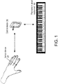
- An electronic musical instrument system includes a sensor device 10 that transmits sensor data to a control device 20, the control device 20 that controls an electronic musical instrument 30, and the electronic musical instrument 30.
- FIG. 1 is a diagram illustrating a configuration of the electronic musical instrument system according to this embodiment.
- the sensor device 10 is a ring-shaped sensor device that is worn by a player of the electronic musical instrument 30. Sensor data which is acquired by the sensor device 10 is transmitted to the control device 20.
- the control device 20 generates a control signal for controlling the electronic musical instrument 30 on the basis of the sensor data acquired from the sensor device 10 and transmits the generated control signal. Accordingly, it is possible to change parameters of musical sound which is output from the electronic musical instrument 30 or to add various effects to the musical sound.
- the sensor device 10, the control device 20, and the electronic musical instrument 30 are wirelessly connected to each other.
- the electronic musical instrument 30 is a synthesizer including musical performance operators which are keys and a sound source.
- the electronic musical instrument 30 generates musical sound corresponding to a musical performance operation which has been performed on the keys and outputs the musical sound from a speaker which is not illustrated.
- the electronic musical instrument 30 changes parameters of musical sound on the basis of a control signal which is transmitted from the control device 20.
- FIG. 2 is a diagram illustrating a hardware configuration of the sensor device 10.
- the sensor device 10 is a sensor that detects an amount of displacement from a position serving as a reference (a reference position) by detecting a posture in a three-dimensional space.
- the sensor device 10 includes a control unit 101, an acceleration sensor 102, and a radio transmission unit 103. These means are driven with electric power which is supplied from a rechargeable battery (not illustrated).
- an object of which a posture is detected by the sensor device 10 is a person's finger.
- the control unit 101 is an operational unit that takes charge of control which is performed by the sensor device 10.
- the control unit 101 is configured as a one-chip microcomputer, in which a processing device that executes a program, a main storage device that is used to execute the program, an auxiliary storage device that stores the program, and the like are incorporated in the same hardware.
- the acceleration sensor 102 is a triaxial acceleration sensor that can acquire acceleration (m/s 2 ) in three directions of an X axis, a Y axis, and a Z axis. Values which are output from the acceleration sensor 102 are acquired by the control unit 101. Three values acquired by the acceleration sensor 102 are referred to as sensor data.
- the X axis, the Y axis, and the Z axis represent axes with respect to the sensor device 10.
- Axes in a global coordinate system are referred to as an X' axis, a Y' axis, and a Z' axis.
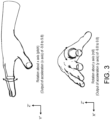
- FIG. 3 is a diagram illustrating the sensor device 10 worn on a finger.
- the control device 20 which will be described later detects an inclination with the X' axis as a rotation axis and an inclination with the Y' axis as a rotation axis on the basis of the sensor data output from the sensor device 10.
- the pitch direction represents an inclination direction with the X' axis as a rotation axis
- the roll direction represents an inclination direction with the Y' axis as a rotation axis
- both the acceleration in the X-axis direction and the acceleration in the Y-axis direction are 0 [m/s 2 ].
- the acceleration in the Y-axis direction is ⁇ 9.8 [m/s 2 ].
- the acceleration in the X-axis direction is ⁇ 9.8 [m/s 2 ].
- control device 20 can recognize an inclination in the pitch direction and an inclination in the roll direction of the sensor device 10 by acquiring the acceleration in the X-axis direction and the acceleration in the Y-axis direction which are output from the sensor device 10.
- the radio transmission unit 103 is a radio communication interface that wirelessly transmits a signal.
- the radio transmission unit 103 transmits the values acquired by the acceleration sensor 102 (a measured value of the acceleration for each axis) to the control device 20.
- the radio transmission unit 103 performs data communication based on the Bluetooth (registered trademark) LowEnergy standard (hereinafter referred to as BLE).
- BLE is a low-energy communication standard using Bluetooth.
- BLE is exemplified, but another radio communication standard can also be used.
- NFC near field communication
- Wi-Fi registered trademark
- Another radio communication system (which includes an independent radio communication system) may be used.
- the above-mentioned means are communicatively connected to each other by a bus.
- FIG. 2 The configuration illustrated in FIG. 2 is an example and some or all of the illustrated functions may be realized using a specially designed circuit. Storage and execution of a program may be performed by combination of the main storage device and the auxiliary storage device which are not illustrated.
- FIG. 4 is a diagram illustrating the hardware configuration of the control device 20.
- the control device 20 is a small-sized computer such as a smartphone, a mobile phone, a tablet computer, a personal digital assistant, a notebook computer, or a wearable computer (such as a smart watch).
- the control device 20 includes a central processing unit (CPU) 201, a ROM 202, a RAM 203, and a radio transmission and reception unit 204.
- the CPU 201 is an operational unit that takes charge of control which is performed by the control device 20.
- the auxiliary storage device 202 is a rewritable nonvolatile memory. A program which is executed by the CPU 201 and data which is used for the control program are stored in the auxiliary storage device 202.
- the auxiliary storage device 202 may store an application into which the program executed by the CPU 201 is packaged.
- the auxiliary storage device 202 may also store an operating system for executing such an application.
- the main storage device 203 is a memory to which a program executed by the CPU 201 and data used for the control program are loaded. By loading a program stored in the auxiliary storage device 202 to the main storage device 203 and causing the CPU 201 to execute the program, the processes which will be described later are performed.
- the radio transmission and reception unit 204 is a radio communication interface that transmits and receives signals to and from the sensor device 10 and the electronic musical instrument 30.
- the radio transmission and reception unit 204 (1) acquires sensor data from the sensor device 10, (2) transmits a control signal which is generated on the basis of the sensor data to the electronic musical instrument 30, and (3) receives a note-on signal and a note-off signal from the electronic musical instrument 30. Details of the respective data will be described later.
- the radio communication system may employ the above-mentioned BLE or another system.
- a system which is used for communication with the sensor device 10 and a system which is used for communication with the electronic musical instrument 30 may be different from each other.
- BLE is used for connection between the control device 20 and the electronic musical instrument 30
- a MIDI over Bluetooth LowEnergy (BLE-MIDI) standard may be used.
- FIG. 4 The configuration illustrated in FIG. 4 is an example and some or all of the illustrated functions may be realized using a specially designed circuit. Storage and execution of a program may be performed by combination of the main storage device and the auxiliary storage device which are not illustrated.
- the electronic musical instrument 30 is a device that synthesizes musical sound on the basis of an operation which is performed on the musical performance operator (the keys) and amplifies and outputs the synthesized musical sound.
- the electronic musical instrument 30 includes a radio transmission and reception unit 301, a CPU 302, a ROM 303, a RAM 304, a musical performance operator 305, a DSP 306, a D/A converter 307, an amplifier 308, and a speaker 309.
- the radio transmission and reception unit 301 is a radio communication interface that transmits and receives signals to and from the control device 20.
- the radio transmission and reception unit 301 is wirelessly connected to the radio transmission and reception unit 204 of the control device 20, and (1) receives a control signal which is generated on the basis of the result of sensing performed by the sensor device 10 from the control device 20 and (2) transmits a note-on signal and a note-off signal to the control device 20. Details of the respective data will be described later.
- the CPU 302 is an operational unit that takes charge of control which is performed by the electronic musical instrument 30. Specifically, processes which are described in this specification, processes of synthesizing musical sound using the DSP 306 which will be described later on the basis of scanning or an operation performed on the musical performance operator 305, and the like are performed.
- the ROM 303 is a rewritable nonvolatile memory.
- a control program which is executed by the CPU 302 and data which is used for the control program are stored in the ROM 303.
- the RAM 304 is a memory to which a control program executed by the CPU 302 and data used for the control program are loaded. By loading a program stored in the ROM 303 to the main storage device 304 and causing the CPU 302 to execute the program, the processes which will be described later are performed.
- FIG. 5 is an example and some or all of the illustrated functions may be realized using a specially designed circuit. Storage and execution of a program may be performed by combination of the main storage device and the auxiliary storage device which are not illustrated.
- the musical performance operator 305 is an interface that receives a musical performance operation of a player.
- the musical performance operator 305 includes keys for carrying out performance and an input interface for designating musical sound parameters or the like (for example, a knob or a push button).
- the DSP 306 is a microprocessor which is specialized for digital signal processing.
- the DSP 306 performs a process specialized for processing a sound signal under the control of the CPU 302. Specifically, the DSP 306 performs synthesis of musical sound, adding an effect to musical sound, and the like on the basis of the musical performance operation and outputs a sound signal.
- the sound signal output from the DSP 306 is converted to an analog signal by the D/A converter 307, amplified by the amplifier 308, and then output from the speaker 309.
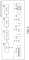
- FIG. 6 is a diagram illustrating the configurations of the electronic musical instrument 30, the control device 20, and the sensor device 10 using functional modules.
- a sensor information transmitting means 1011 transmits sensor data acquired by the acceleration sensor 102 to the control device 20.
- the sensor information transmitting means 1011 is realized by the control unit 101.
- a control means 2011 acquire sensor data from the sensor device 10 and receives a note-on signal and a note-off signal from the electronic musical instrument 30.
- the control means 2011 generates a control signal on the basis of the sensor data acquired from the sensor device 10 and transmits the generated control signal to the electronic musical instrument 30.
- the control means 2011 is realized by the CPU 201.
- a musical performance signal transmitting means 3021 transmits a note-on signal and a note-off signal to the control device 20 according to a musical performance operation.
- a control signal reception means 3022 receives the control signal from the control device 20 and performs processing based on parameters which are included in the control signal.
- the musical performance signal transmitting means 3021 and the control signal reception means 3022 are realized by the CPU 302.
- the control means 2011 corresponds to a "control means” in the disclosure.
- the musical performance signal transmitting means 3021 corresponds to a "transmission means” in the disclosure.
- the sensor device 10 and the control device 20 correspond to a “controller” in the disclosure.
- the electronic musical instrument 30 corresponds to a "musical performance device” and a “sound generation device” in the disclosure.
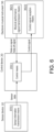
- FIG. 7 is a diagram schematically illustrating data which is transmitted and received between the elements and processes.
- the electronic musical instrument 30 (the musical performance signal transmitting means 3021) transmits a note-on signal and a note-off signal to the control device 20 according to a musical performance operation
- the control device 20 (the control means 2011) detects that the electronic musical instrument 30 emits sound on the basis of the note-on signal and the note-off signal.
- the note-on signal is a signal indicating that a key has been pressed
- the note-off signal is a signal indicating that a finger has been removed from a key.
- information indicating a channel, a note number, a velocity, or the like is generally added to the note-on signal and the note-off signal, but such information is not used in this embodiment.
- the control device 20 acquires sensor data from the sensor device 10 (the sensor information transmitting means 1011) at a time at which emission of sound from the electronic musical instrument 30 has started, and stores a reference value on the basis of the sensor data (S1).
- the reference value is a value indicating acceleration in the X-axis direction and acceleration in the Y-axis direction of the sensor device 10.
- the step of determining the reference value corresponds to "setting of the reference position" in the disclosure.
- FIG. 8 is a diagram illustrating the posture of the sensor device 10 at a time at which a key is pressed.
- ⁇ that is, a rotation angle in the pitch direction
- the acceleration in the Y-axis direction is cos30° ⁇ 9.8 ⁇ 1.5 [m/s 2 ] (hereinafter, the unit of acceleration is omitted unless necessary). Accordingly, this value is stored as the reference value in the pitch direction.
- the reference value in the roll direction is stored in the same way.
- the control device 20 calculates an amount of displacement from the reference value on the basis of the sensor data acquired from the sensor device 10 (the sensor information transmitting means 1011), generates a control signal corresponding to the amount of displacement, and transmits the control signal to the electronic musical instrument 30 (the control signal reception means 3022) (S2).
- a control signal corresponding to a difference (+1.0) therebetween is generated and transmitted to the electronic musical instrument 30.
- a control signal corresponding to a difference (-1.5) therebetween is generated and transmitted to the electronic musical instrument 30.
- a signal for designating expression and a signal for designating pitch bend are generated as the control signal.
- the signal for designating expression corresponds to the inclination in the pitch direction and the signal for designating pitch bend corresponds to the inclination in the roll direction. Accordingly, control of musical sound based on a posture of a hand becomes possible.
- the set reference position is cleared at a time at which the emission of sound from the electronic musical instrument 30 has stopped completely (S3). Whether the emission of sound from the electronic musical instrument 30 has stopped completely can be determined by counting a note-on signal and a note-off signal. For example, when the note-on signal has been transmitted three times and the note-off signal has been subsequently transmitted three times, it can be determined that the emission of sound has stopped.
- the reference position is cleared at the time at which the emission of sound has stopped completely, and a new reference position is set at a time at which the emission of sound has started again. Accordingly, regardless of a posture of a hand of a player who plays the keyboard instrument, it is possible to appropriately change expression and pitch bend.
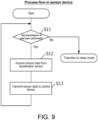
- FIG. 9 is a flowchart illustrating a process flow which is performed by the sensor device 10. The process flow illustrated in FIG. 9 is repeatedly performed by the control unit 101 (the sensor information transmitting means 1011) while the sensor device 10 is being powered on.
- Step S11 it is determined whether sensor data needs to be transmitted to the control device 20. For example, when the sensor device 10 is not used, it is not necessary to transmit the sensor data. Therefore, when it is determined that sensor data does not need to be transmitted, the control unit 101 causes the host device to transition to a sleep mode. In the sleep mode, the sensor device 10 stops the functions thereof other than minimal functions which are required for determining return from the sleep mode. When it has returned from the sleep mode, the process flow illustrated in FIG. 9 is restarted.
- Whether or not the sensor device 10 is used can be determined, for example, by detecting that the sensor data acquired by the acceleration sensor (the acceleration of three axes) does not change in a predetermined period. Other conditions may be used.
- a power supply of the acceleration sensor 102 may be turned off or only radio transmission of the sensor data may be stopped while acquisition of the sensor data continues. Only generation of transmission data may be stopped while radio transmission continues.
- Step S12 sensor data is acquired from the acceleration sensor 102.
- Step S13 the acquired sensor data is transmitted to the control device 20 via the radio transmission unit 103.
- the process flow which is performed by the control device 20 is roughly classified into a process flow when a note-on signal and a note-off signal are received from the electronic musical instrument 30 and a process flow when sensor data is received from the sensor device 10.
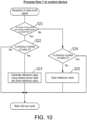
- the process flow when a note-on signal and a note-off signal are received from the electronic musical instrument 30 will be first described below with reference to FIG. 10 .
- Step S21 it is determined whether the number of notes which are currently emitted is equal to or greater than 1 on the basis of the received signal.
- the number of notes which are currently emitted is equal to or greater than 1
- the previous number of notes is equal to or greater than 1 (S22: NO)
- Step S22 When the determination result of Step S22 is positive, it means that emission of sound is newly started, and thus a reference value is generated on the basis of the newest sensor data and is stored in Step S23. Specifically, the acceleration in the Y-axis direction is stored as the reference value in the pitch direction and the acceleration in the X-axis direction is stored as the reference value in the roll direction.
- Step S21 When it is determined in Step S21 that the number of notes which are currently emitted is 0 (S21: NO), it is determined in Step S24 whether the previous number of notes is 0. When the previous number of notes is 0 (S24: YES), it means that a state in which sound is not emitted continues, and thus the next cycle is waited for without performing any particular process. When the previous number of notes is equal to or greater than 1 (S24: NO), it means that emission of sound has stopped, and thus the reference value (in both the pitch direction and the roll direction) is cleared (is initialized to a predetermined value) in Step S25.
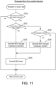
- FIG. 11 is a diagram illustrating a process flow of transmitting a control signal to change an expression value
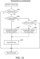
- FIG. 12 is a diagram illustrating a process flow of transmitting a control signal to change a pitch bend value.
- the process flows illustrated in FIGS. 11 and 12 are performed in parallel whenever sensor data is received from the sensor device 10.
- Step S31 it is determined whether the reference value in the pitch direction has been set.
- the reference value in the pitch direction has not been set (which includes a case in which the reference value has been cleared)
- the reference value in the pitch direction has been set, it is determined in Step S32 whether an operating condition has been satisfied (whether a condition that an expression value has to be set has been satisfied).
- Step S32 will be described below in detail.
- the acceleration acquired by the sensor device 10 is compared with preset acceleration (the reference value) and an expression value or a pitch bend value is set on the basis of an amount of displacement therebetween, but the expression value or the pitch bend value may change due to movement of a finger which performs a musical performance operation when this method is used.
- Step S32 an amount of displacement is acquired by comparing current acceleration (the acceleration in the Y-axis direction) with the set reference value (the reference value in the pitch direction), it is determined whether the amount of displacement is within a range of a margin, and it is determined that the operating condition has not been satisfied (the condition that the expression value has to be set has not been satisfied) when the amount of displacement is not within the range of the margin.
- the range of the margin has a value which varies according to the absolute value of the reference value.
- the horizontal axis represents the absolute value of the set reference value and the vertical axis represents the range of the margin.
- the range of the margin is set to " ⁇ 1.0" when the absolute value of the set reference value is less than 4.0, and the range of the margin is set to " ⁇ 0.2" when the absolute value of the set reference value is equal to or greater than 4.0 and less than 7.0.
- the range of the margin is set in two steps, but the range of the margin may be set in multiple steps or may change linearly.
- Step S32 When the determination result of Step S32 is positive, a MIDI message is generated on the basis of the calculated amount of displacement. Specifically, as illustrated in FIG. 14 , the expression value is determined on the basis of the amount of displacement from the reference value, and the MIDI message for designating the expression value is generated (Step S33). The generated message is transmitted to the electronic musical instrument 30 in Step S34.
- Step S32 When the determination result of Step S32 is negative, that is, when the acquired amount of displacement is within the range of the margin, it is determined whether the current expression value is a median value (for example, 64) (Step S35). When the current expression value is not a median value, a MIDI message for designating the median value is generated (Step S36). When the current expression value is already the median value, the process flow ends and the next cycle is awaited.
- a median value for example, 64
- the process flow illustrated in FIG. 12 is different from the process flow described above with reference to FIG. 11 in that the reference value in the roll direction is used in Step S41 and the reference value in the roll direction is compared with the acceleration in the X-axis direction in Step S42.
- Step S43 the two process flows are different from each other in that a MIDI message for designating the pitch bend value (-8192 to 8191) is generated instead of the expression value (0 to 127).
- Step S42 When the determination result of Step S42 is negative, that is, when the acquired amount of displacement is within the range of the margin, it is determined whether the current pitch bend value is a median value (for example, 0) (Step S45). When the current pitch bend value is not the median value, a MIDI message for designating the median value is generated (Step S46). When the current pitch bend value is already the median value, the process flow ends and the next cycle is awaited.
- a median value for example, 0
- the range of the margin may differ between the expression and the pitch bend.
- a player can control musical sound with natural movement. Since a reference value of acceleration is stored at the time at which emission of sound from the electronic musical instrument 30 has started and the same reference value is used until emission of sound stops, it is possible to perform natural control that does not depend on a performance method. By providing a margin for an amount of displacement of acceleration, it is possible to curb unnecessary variation of musical sound parameters.
- Step S11 the sensor device 10 detects that acceleration does not change and performs a transition to the sleep mode.
- the control device 20 determines whether emission of sound from the electronic musical instrument 30 has stopped and causes the sensor device 10 to the sleep mode on the basis of the result of determination.
- the control device 20 transmits a sleep signal to the sensor device 10 at the time of Step S25 illustrated in FIG. 10 .
- the determination result of Step S11 is negative and the sensor device 10 transitions to the sleep mode. Accordingly, the functions of the sensor device 10 other than the functions required for determining return from sleep (wake-up) stop.
- Step S22 the control device 20 transmits a wake-up signal to the sensor device 10.
- the process flow illustrated in FIG. 9 is restarted. After the wake-up signal has been transmitted, it is preferable that the process flow wait until sensor data is received and progress to Step S23.
- the second embodiment it is possible to determine that sensor data does not need to be transmitted even when a player wears the sensor device 10 and to transition to a power save mode. That is, it is possible to achieve a greater effect of power save.
- the sensor device 10 includes the acceleration sensor 102.
- a third embodiment is an embodiment in which the sensor device 10 further includes an angular velocity sensor and a geomagnetic sensor.
- FIG. 15 is a diagram illustrating a hardware configuration of the sensor device 10 according to the third embodiment.
- the sensor device 10 further includes an angular velocity sensor 104 and a geomagnetic sensor 105.
- the angular velocity sensor 104 is a triaxial angular velocity sensor that can acquire an angular velocity (deg/s) with each of the X axis, the Y axis, and the Z axis (in the sensor coordinate system) as a rotation axis. Values which are output from the angular velocity sensor 104 are acquired by the control unit 101.
- the geomagnetic sensor 105 is a triaxial geomagnetic sensor that can acquire a value of magnetic force in a direction corresponding to each of the X axis, the Y axis, and the Z axis (in the sensor coordinate system). Values which are output from the geomagnetic sensor 105 are acquired by the control unit 101.
- one of the acceleration sensor 102, the angular velocity sensor 104, and the geomagnetic sensor 105 can be selected as a sensor which is used for control of the electronic musical instrument 30. This selection may be performed, for example, by switching a switch which is provided in the sensor device 10 or may be performed by rewriting parameters which are set in the control unit 101 through radio communication.
- the control device 20 can acquire an amount of rotation of the sensor device 10 from a time at which integration has started by integrating the angular velocity which has been acquired every unit time. For example, the integration is started at the time at which the reference value is set in Step S 1 and a control signal based on the integrated amount of rotation is generated in Step S2. In Step S3, the integration is stopped. Accordingly, the same advantageous effects as in the first embodiment can be achieved.
- the control device 20 can acquire a posture in a three-dimensional space of the sensor device 10 on the basis of the detected direction of the magnetic north.
- the detected acceleration is used without any change, but when the geomagnetic sensor is used, the acceleration can be replaced with a magnetic force or an inclination angle.
- a fourth embodiment is an embodiment in which a gesture is detected by combination of two or more of the acceleration sensor, the angular velocity sensor, and the geomagnetic sensor and a control signal for the electronic musical instrument 30 is generated on the basis of the result of detection.
- the hardware configuration of the sensor device 10 according to the fourth embodiment is the same as that of the third embodiment.
- a plurality of pieces of sensor data corresponding to a plurality of sensors are periodically transmitted to the control device 20 in Step S13.
- a reference value is set for each sensor and for each axis in the process of setting the reference value (Step S23). For example, values of acceleration in the X-axis, Y-axis, and Z-axis directions output from the acceleration sensor and values of magnetic forces in the X-axis, Y-axis, and Z-axis directions output from the geomagnetic sensor are set as the reference values. Regarding the angular velocity sensor, an integration start time is determined instead of storing output values thereof.
- Step S23 a posture in a three-dimensional space of each sensor is acquired in Step S23. That is, the reference position in the present disclosure is set.
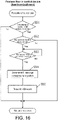
- the process flow illustrated in FIG. 16 is performed by the control device 20 (the control means 2011) instead of the process flows illustrated in FIGS. 11 and 12 .
- Step S51 it is determined whether a reference position for each sensor has been set.
- the reference positions have not been set (which includes a case in which the reference positions are cleared)
- the reference values for all the sensors have been set, it is determined in Step S52 whether an operating condition has been satisfied.
- Step S52 it is determined whether sensor data acquired from each sensor is in a range of a margin.
- the range of the margin can be appropriately set depending on the types of the sensors.
- Step S53 it is determined whether a predetermined gesture has been taken with reference to a plurality of pieces of sensor data.
- a motion including (1) rotating a right hand which is used for playing a keyboard instrument by 90 degrees to the right side with a forearm as an axis and (2) rotating a direction in which a finger is directed 90 degrees is assumed to be a predetermined gesture.
- a reference value is set in a state in which the sensor device 10 is worn on the right hand, the palm is tilted, and a fingertip faces a direction of 0 degrees (north) and when (1) a thumb faces upward and (2) the fingertip faces a direction of 90 degrees (east), it is determined that the predetermined gesture (a shaking gesture) has been made.
- the thumb facing upward can be detected by the acceleration sensor or the angular velocity sensor, and the fingertip facing the direction of 90 degrees can be detected by the geomagnetic sensor. In this way, what gesture has been made can be determined on the basis of the sensor data output from a plurality of sensors. In this step, whether conditions (values) which should be satisfied by a plurality of pieces of sensor data have been simultaneously satisfied may be determined, or whether the plurality of pieces of sensor data have been satisfied in predetermined order may be determined.
- a MIDI message corresponding to the gesture is generated in Step S54 and is transmitted in Step S55.
- a MIDI message of "setting an expression value to 0" can be allocated to the gesture. In this case, the sound volume becomes zero by making the gesture.
- a gesture can be detected using a plurality of sensors, and a control signal can be generated on the basis of the detected gesture and can be transmitted.
- a value is changed in real time on the basis of the value output from the sensor, but an arbitrary control signal can be allocated to an arbitrary gesture in this embodiment.
- a plurality of control signals can be allocated to a plurality of different gestures.
- a synthesizer has been exemplified as the electronic musical instrument 30, but another musical instrument may be connected.
- a musical instrument in which a musical performance operator and a sound source are separated from each other may be employed.
- a configuration in which a note-on signal or a note-off signal is received from a device including the musical performance operator and a control signal (a MIDI message) is transmitted to a device including the sound source may be employed.
- a target device to which the control signal is to be transmitted may not be the device including the sound source.
- the target device may be a device that adds an effect to input sound (an effector).
- the note-on signal and the note-off signal in the MIDI standard are used, but a message of another standard may be used as long as they are signals for notifying of sound emission start and sound emission stop.
- the sensor device 10 merely performs only transmission of sensor data and the control device 20 generates a control signal on the basis of the sensor data, but the present disclosure is not limited to the embodiments.
- the functions of the sensor device 10 and the control device 20 may be collected in one piece of hardware and the piece of hardware may be worn on a player's hand.
- the sensor device 10 acquires a value indicating an inclination (acceleration in a predetermined axis direction) of the device, but in an additional example not covered by the claims, the acquired information may be information indicating a parameter other than the inclination.
- information indicating a relative position between a player or a musical instrument and a sensor or an absolute position of the sensor may be used.
- a distance between a musical instrument and a sensor may be set as a reference value and a difference in distance may be used as an amount of displacement.
- expression and pitch bend have been exemplified as the musical sound parameters, but other musical sound parameters may be controlled as long as they can control a sound-emitting state.
- a control signal for designating modulation, pan, or sustain may be generated.
Landscapes
- Engineering & Computer Science (AREA)
- Physics & Mathematics (AREA)
- Acoustics & Sound (AREA)
- Multimedia (AREA)
- Computer Networks & Wireless Communication (AREA)
- Electrophonic Musical Instruments (AREA)
Claims (16)
- Musikinstrument-Steuerung (10, 20), die umfasst:ein Empfangsmittel (3022), das ein Tonemissions-Startsignal empfängt, das basierend auf einem musikalischen Darbietungsvorgang, von einer musikalischen Darbietungsvorrichtung (30) übertragen wird;einen Sensor (10), der einen Verschiebungsbetrag von einer Referenzposition erfasst; undein Steuermittel (20, 2011), das ein Steuersignal, basierend auf dem Verschiebungsbetrag von der Referenzposition erzeugt und das Steuersignal an eine Tonerzeugungsvorrichtung (30) überträgt,wobei das Steuermittel (20, 2011) die Referenzposition, basierend auf dem Tonemissions-Startsignal einstellt, empfangen von der musikalischen Darbietungsvorrichtung (30),wobei die Musikinstrument-Steuerung (10, 20), dadurch gekennzeichnet ist, dass der Sensor (10) ein triaxialer Beschleunigungssensor ist, undder Verschiebungsbetrag aus der Referenzposition ein Wert ist, der einen Betrag von Neigung aus einer Haltung anzeigt.
- Musikinstrument-Steuerung (10, 20) gemäß Anspruch 1, wobei das Steuermittel (20, 2011) das Steuersignal erzeugt, wenn der Verschiebungsbetrag von der Referenzposition eine vorbestimmte Bedingung erfüllt.
- Musikinstrument-Steuerung (10, 20) gemäß einem der Ansprüche 1 oder 2, wobei das Tonemissions-Startsignal ein Note-On-Signal ist.
- Musikinstrument-Steuerung (10, 20) gemäß einem der Ansprüche 1 bis 3, wobei das Empfangsmittel (3022) ferner ein Tonemissions-Stoppsignal empfängt, das basierend auf einem musikalischen Darbietungsvorgang gesendet wird, und
wobei das Steuermittel (20, 2011) bestimmt, ob ein Übergang von einem nicht-Tonemissionszustand in einen Tonemissionszustand, basierend auf dem Tonemission-Startsignal und dem Tonemissions-Stoppsignal, aufgetreten ist, und die Referenzposition einstellt, wenn der Übergang aufgetreten ist. - Musikinstrument-Steuerung (10, 20) gemäß Anspruch 4, wobei das Steuermittel (20, 2011) bestimmt, ob der Übergang von dem Tonemissionszustand in den nicht-Tonemissionszustand aufgetreten ist, basierend auf dem Tonemissions-Startsignal und dem Tonemissions-Stoppsignal, und die Referenzposition auf einen vorbestimmten Wert initialisiert, wenn der Übergang aufgetreten ist.
- Musikinstrument-Steuerung (10, 20) gemäß Anspruch 4 oder 5, wobei das Tonemissions-Stoppsignal ein Note-Off-Signal ist.
- Musikinstrument-Steuerung (10, 20) gemäß einem der Ansprüche 1 bis 6, wobei der Sensor (10) einen Abtastvorgang in einem Zustand stoppt, in dem kein musikalischer Darbietungsvorgang an der musikalischen Darbietungsvorrichtung (30) durchgeführt wird.
- Musikinstrument-Steuerung (10, 20) gemäß Anspruch 1, wobei der Verschiebungsbetrag einen ersten Verschiebungsbetrag, entsprechend einer Neigung mit einer ersten Richtung als eine Drehachse und einen zweiten Verschiebungsbetrag, entsprechend einer Neigung mit einer zweiten Richtung senkrecht zu der ersten Richtung als eine Drehachse enthält, und
wobei das Steuermittel (20, 2011) ein erstes Steuersignal, basierend auf dem ersten Verschiebungsbetrag erzeugt und ein zweites Steuersignal, basierend auf dem zweiten Verschiebungsbetrag, erzeugt. - Musikinstrument-Steuerung (10, 20) gemäß Anspruch 8, wobei das erste Steuersignal und das zweite Steuersignal Signale zum Steuern eines Tonemissionszustands sind.
- Musikinstrument-Steuerung (10, 20) gemäß Anspruch 8 oder 9, wobei das erste Steuersignal ein Signal zur Bestimmung von Ausdruck ist, und
wobei das zweite Steuersignal ein Signal zur Bestimmung einer gleitenden Tonhöhenänderung ist. - Musikinstrument-Steuerung (10, 20) gemäß einem der Ansprüche 9 bis 10, wobei das Steuermittel (20, 2011) das Steuersignal mit einem vorbestimmten Wert erzeugt, wenn der Verschiebungsbetrag von der Referenzposition gleich oder kleiner als ein Schwellenwert ist.
- Musikinstrument-Steuerung (10, 20) gemäß Anspruch 11, wobei der Schwellenwert in dem Fall abnimmt, in dem ein Absolutwert des Betrags von Neigung zunimmt, wenn die Referenzposition eingestellt wurde.
- Musikinstrument-Steuerung (10, 20) gemäß einem der Ansprüche 1 bis 12, wobei die musikalische Darbietungsvorrichtung (30) eine musikalische Darbietungsvorrichtung ist, die Tasten enthält, und
wobei der Sensor (10) ein Sensor ist, der an einem Finger getragen wird. - Elektronisches Musikinstrumentensystem, umfassend eine musikalische Darbietungsvorrichtung (30) und eine Steuerung (10, 20),wobei die musikalische Darbietungsvorrichtung (30) ein Übertragungsmittel (3021) enthält, das ein Tonemissions-Startsignal an die Steuerung (10, 20), basierend auf einem musikalischen Darbietungsvorgang überträgt,wobei die Steuerung (10, 20) enthält:einen Sensor (10), der einen Verschiebungsbetrag von einer Referenzposition erfasst; undein Steuermittel (20, 2011), das ein Steuersignal, basierend auf dem Verschiebungsbetrag, von der Referenzposition erzeugt und das Steuersignal an eine Tonerzeugungsvorrichtung (30) überträgt, undwobei das Steuermittel (20, 2011) die Referenzposition, basierend auf dem Tonemissions-Startsignal einstellt, empfangen von der musikalischen Darbietungsvorrichtung (30),wobei das elektronische Musikinstrumentensystem dadurch gekennzeichnet ist, dass der Sensor (10) ein triaxialer Beschleunigungssensor ist, undder Verschiebungsbetrag von der Referenzposition ein Wert ist, der einen Betrag von Neigung von einer Haltung anzeigt.
- Steuerungsverfahren, das von einer Musikinstrument-Steuerung (10, 20) durchgeführt wird, die einen Sensor (10) enthält, wobei das Steuerungsverfahren umfasst:einen Empfangsschritt des Empfangens eines Tonemissions-Startsignals, das basierend auf einem musikalischen Darbietungsvorgang von einer musikalischen Darbietungsvorrichtung (30) übertragen wird;einen Erfassungsschritt des Erfassens von Informationen zum Detektieren eines Verschiebungsbetrags von einer Referenzposition; undeinen Steuerschritt des Erzeugens eines Steuersignals, basierend auf dem Verschiebungsbetrag von der Referenzposition und des Übertragens des Steuersignals an eine Tonerzeugungsvorrichtung (30),wobei der Steuerschritt Einstellen der Referenzposition, basierend auf dem Tonemissionsstartsignal, empfangen von der musikalischen Darbietungsvorrichtung (30) enthält,wobei das Steuerverfahren dadurch gekennzeichnet ist, dass der Sensor (10) ein triaxialer Beschleunigungssensor ist, undder Verschiebungsbetrag von der Referenzposition ein Wert ist, der einen Betrag von Neigung von einer Haltung anzeigt.
- Steuerungsverfahren gemäß Anspruch 15, wobei das Steuerungsverfahren ferner durch eine musikalische Darbietungsvorrichtung (30) und die Musikinstrument-Steuerung (10, 20) durchgeführt wird,
wobei die musikalische Darbietungsvorrichtung (30) einen Übertragungsschritt des Übertragens eines Tonemissions-Startsignals an die Musikinstrument-Steuerung (10, 20), basierend auf einem musikalischen Darbietungsvorgang, durchführt.
Applications Claiming Priority (2)
| Application Number | Priority Date | Filing Date | Title |
|---|---|---|---|
| JP2018084489A JP2021107843A (ja) | 2018-04-25 | 2018-04-25 | 電子楽器システムおよび楽器用コントローラ |
| PCT/JP2018/025602 WO2019207813A1 (ja) | 2018-04-25 | 2018-07-05 | 楽器用コントローラおよび電子楽器システム |
Publications (3)
| Publication Number | Publication Date |
|---|---|
| EP3786941A1 EP3786941A1 (de) | 2021-03-03 |
| EP3786941A4 EP3786941A4 (de) | 2022-01-19 |
| EP3786941B1 true EP3786941B1 (de) | 2023-02-15 |
Family
ID=68295227
Family Applications (1)
| Application Number | Title | Priority Date | Filing Date |
|---|---|---|---|
| EP18916925.3A Active EP3786941B1 (de) | 2018-04-25 | 2018-07-05 | Musikinstrumentensteuergerät und elektronisches musikinstrumentensystem |
Country Status (4)
| Country | Link |
|---|---|
| US (1) | US11688375B2 (de) |
| EP (1) | EP3786941B1 (de) |
| JP (1) | JP2021107843A (de) |
| WO (1) | WO2019207813A1 (de) |
Families Citing this family (4)
| Publication number | Priority date | Publication date | Assignee | Title |
|---|---|---|---|---|
| CN112020742B (zh) * | 2018-04-19 | 2024-08-13 | 罗兰株式会社 | 电乐器系统及其控制方法 |
| JP2021107843A (ja) * | 2018-04-25 | 2021-07-29 | ローランド株式会社 | 電子楽器システムおよび楽器用コントローラ |
| JP7432347B2 (ja) * | 2019-12-04 | 2024-02-16 | ローランド株式会社 | 楽音制御装置、及び楽音制御方法 |
| GB2611021B (en) * | 2021-08-27 | 2024-06-26 | Little People Big Noise Ltd | Gesture-based audio syntheziser controller |
Family Cites Families (32)
| Publication number | Priority date | Publication date | Assignee | Title |
|---|---|---|---|---|
| JPH0738109B2 (ja) * | 1989-03-31 | 1995-04-26 | ヤマハ株式会社 | 電子楽器 |
| US5119709A (en) * | 1989-04-14 | 1992-06-09 | Yamaha Corporation | Initial touch responsive musical tone control device |
| JP2636463B2 (ja) | 1990-04-06 | 1997-07-30 | ヤマハ株式会社 | ヘッドコントローラ |
| JPH04100097A (ja) * | 1990-08-18 | 1992-04-02 | Casio Comput Co Ltd | 電子楽器 |
| US5489922A (en) * | 1993-12-08 | 1996-02-06 | Hewlett-Packard Company | Hand worn remote computer mouse |
| JP3355743B2 (ja) * | 1993-12-28 | 2002-12-09 | ヤマハ株式会社 | 電子鍵盤楽器 |
| US5949012A (en) * | 1995-12-27 | 1999-09-07 | Kabushiki Kaisha Kawai Gakki Seisakusho | Electronic musical instrument and music performance information inputting apparatus capable of inputting various music performance information with simple operation |
| US5920024A (en) * | 1996-01-02 | 1999-07-06 | Moore; Steven Jerome | Apparatus and method for coupling sound to motion |
| JP3646599B2 (ja) * | 2000-01-11 | 2005-05-11 | ヤマハ株式会社 | 演奏インターフェイス |
| FR2821201B1 (fr) * | 2001-02-16 | 2003-05-02 | Gilbert Javelle | Dispositif pour piloter un instrument de musique electronique du type boite a sons |
| JP3812387B2 (ja) * | 2001-09-04 | 2006-08-23 | ヤマハ株式会社 | 楽音制御装置 |
| JP2006134066A (ja) | 2004-11-05 | 2006-05-25 | Kopeck Japan:Kk | ウェアラブルスイッチ |
| JP2006293210A (ja) | 2005-04-14 | 2006-10-26 | Sony Corp | 電子機器およびデータ処理方法 |
| JP2006337505A (ja) * | 2005-05-31 | 2006-12-14 | Sony Corp | 音楽再生装置および処理制御方法 |
| JP2007041770A (ja) | 2005-08-02 | 2007-02-15 | Nec Tokin Corp | 使用者識別システム |
| JP4720563B2 (ja) | 2006-03-22 | 2011-07-13 | ヤマハ株式会社 | 楽音制御装置 |
| JP2008122644A (ja) | 2006-11-13 | 2008-05-29 | Casio Comput Co Ltd | 演奏教習システムおよび演奏教習方法 |
| JP2011123248A (ja) * | 2009-12-10 | 2011-06-23 | Yamaha Corp | 音量制御装置、楽音制御装置、再生装置及びプログラム |
| JP5099176B2 (ja) * | 2010-06-15 | 2012-12-12 | カシオ計算機株式会社 | 演奏装置および電子楽器 |
| JP5029732B2 (ja) * | 2010-07-09 | 2012-09-19 | カシオ計算機株式会社 | 演奏装置および電子楽器 |
| JP5848520B2 (ja) * | 2011-05-11 | 2016-01-27 | 任天堂株式会社 | 音楽演奏プログラム、音楽演奏装置、音楽演奏システム、および音楽演奏方法 |
| WO2013090831A2 (en) * | 2011-12-14 | 2013-06-20 | Smule, Inc. | Synthetic multi-string musical instrument with score coded performance effect cues and/or chord sounding gesture capture |
| JP6044099B2 (ja) * | 2012-04-02 | 2016-12-14 | カシオ計算機株式会社 | 姿勢検出装置、方法及びプログラム |
| JP6102372B2 (ja) * | 2013-03-14 | 2017-03-29 | カシオ計算機株式会社 | 演奏システム、演奏方法及びプログラム |
| GB201315228D0 (en) * | 2013-08-27 | 2013-10-09 | Univ London Queen Mary | Control methods for expressive musical performance from a keyboard or key-board-like interface |
| JP2017168060A (ja) | 2016-03-14 | 2017-09-21 | 明久 松園 | スマートインターフェースリング |
| JP2021107843A (ja) * | 2018-04-25 | 2021-07-29 | ローランド株式会社 | 電子楽器システムおよび楽器用コントローラ |
| EP3881910A4 (de) * | 2018-11-15 | 2022-01-12 | Sony Group Corporation | Informationsverarbeitungsvorrichtung, informationsverarbeitungsverfahren und programm |
| JP7307906B2 (ja) * | 2019-02-01 | 2023-07-13 | 後藤ガット有限会社 | 楽器用調律器 |
| JP7574797B2 (ja) * | 2019-08-22 | 2024-10-29 | ソニーグループ株式会社 | 信号処理装置および方法、並びにプログラム |
| JP7480749B2 (ja) * | 2021-05-21 | 2024-05-10 | カシオ計算機株式会社 | 電子楽器、電子楽器の制御方法及びプログラム |
| CN114974185A (zh) * | 2021-12-27 | 2022-08-30 | 王贺新 | 迷你电子键盘乐器 |
-
2018
- 2018-04-25 JP JP2018084489A patent/JP2021107843A/ja active Pending
- 2018-07-05 WO PCT/JP2018/025602 patent/WO2019207813A1/ja not_active Ceased
- 2018-07-05 EP EP18916925.3A patent/EP3786941B1/de active Active
- 2018-07-05 US US17/049,964 patent/US11688375B2/en active Active
Also Published As
| Publication number | Publication date |
|---|---|
| US11688375B2 (en) | 2023-06-27 |
| WO2019207813A1 (ja) | 2019-10-31 |
| US20210241737A1 (en) | 2021-08-05 |
| JP2021107843A (ja) | 2021-07-29 |
| EP3786941A1 (de) | 2021-03-03 |
| EP3786941A4 (de) | 2022-01-19 |
Similar Documents
| Publication | Publication Date | Title |
|---|---|---|
| EP2975497B1 (de) | Endgerätevorrichtung, endgerätevorrichtungsteuerungsverfahren und programm | |
| US11688375B2 (en) | Musical instrument controller, electronic musical instrument system, and control method thereof | |
| US9207781B2 (en) | Input apparatus, control system, handheld apparatus, and calibration method | |
| US9778775B2 (en) | Electronic device and method of controlling electronic device using grip sensing | |
| US9223405B2 (en) | Apparatus and method for inputting information based on events | |
| JP4626671B2 (ja) | 入力装置及び制御システム | |
| CN101627281A (zh) | 输入装置、控制装置、控制系统、控制方法和手持装置 | |
| US10173130B2 (en) | Information processing system, extended input device, and information processing method | |
| JP6787338B2 (ja) | 力覚提示装置、力覚提示方法及びプログラム | |
| JP6270557B2 (ja) | 情報入出力装置及び情報入出力方法 | |
| US20200293603A1 (en) | Attitude Matrix Calculation Method and Device | |
| AU2010350920A1 (en) | Gun-shaped game controller | |
| US9958902B2 (en) | Input device, input method, and program | |
| Paradiso et al. | Instrumented footwear for interactive dance | |
| JP2010152587A (ja) | 入力装置、制御システム、ハンドヘルド装置及び校正方法 | |
| KR101752320B1 (ko) | 장갑 컨트롤러 시스템 | |
| JP2013508828A (ja) | ヒューマンマシンインタフェースデバイス | |
| KR102274585B1 (ko) | 포인팅 디바이스를 구비한 전자 탬버린을 이용한 노래방 시스템 | |
| GB2559815A (en) | Music control device | |
| KR20160089982A (ko) | 동작인식센서를 이용한 입력장치 | |
| JP2022178973A (ja) | 入力デバイス | |
| KR20130093948A (ko) | 활동 추적 장치 |
Legal Events
| Date | Code | Title | Description |
|---|---|---|---|
| STAA | Information on the status of an ep patent application or granted ep patent |
Free format text: STATUS: THE INTERNATIONAL PUBLICATION HAS BEEN MADE |
|
| PUAI | Public reference made under article 153(3) epc to a published international application that has entered the european phase |
Free format text: ORIGINAL CODE: 0009012 |
|
| STAA | Information on the status of an ep patent application or granted ep patent |
Free format text: STATUS: REQUEST FOR EXAMINATION WAS MADE |
|
| 17P | Request for examination filed |
Effective date: 20201120 |
|
| AK | Designated contracting states |
Kind code of ref document: A1 Designated state(s): AL AT BE BG CH CY CZ DE DK EE ES FI FR GB GR HR HU IE IS IT LI LT LU LV MC MK MT NL NO PL PT RO RS SE SI SK SM TR |
|
| AX | Request for extension of the european patent |
Extension state: BA ME |
|
| DAV | Request for validation of the european patent (deleted) | ||
| DAX | Request for extension of the european patent (deleted) | ||
| A4 | Supplementary search report drawn up and despatched |
Effective date: 20211221 |
|
| RIC1 | Information provided on ipc code assigned before grant |
Ipc: G10H 1/053 20060101ALI20211215BHEP Ipc: G10H 1/00 20060101AFI20211215BHEP |
|
| GRAP | Despatch of communication of intention to grant a patent |
Free format text: ORIGINAL CODE: EPIDOSNIGR1 |
|
| STAA | Information on the status of an ep patent application or granted ep patent |
Free format text: STATUS: GRANT OF PATENT IS INTENDED |
|
| INTG | Intention to grant announced |
Effective date: 20220929 |
|
| GRAS | Grant fee paid |
Free format text: ORIGINAL CODE: EPIDOSNIGR3 |
|
| GRAA | (expected) grant |
Free format text: ORIGINAL CODE: 0009210 |
|
| STAA | Information on the status of an ep patent application or granted ep patent |
Free format text: STATUS: THE PATENT HAS BEEN GRANTED |
|
| AK | Designated contracting states |
Kind code of ref document: B1 Designated state(s): AL AT BE BG CH CY CZ DE DK EE ES FI FR GB GR HR HU IE IS IT LI LT LU LV MC MK MT NL NO PL PT RO RS SE SI SK SM TR |
|
| REG | Reference to a national code |
Ref country code: CH Ref legal event code: EP Ref country code: GB Ref legal event code: FG4D |
|
| REG | Reference to a national code |
Ref country code: DE Ref legal event code: R096 Ref document number: 602018046294 Country of ref document: DE |
|
| REG | Reference to a national code |
Ref country code: AT Ref legal event code: REF Ref document number: 1548640 Country of ref document: AT Kind code of ref document: T Effective date: 20230315 Ref country code: IE Ref legal event code: FG4D |
|
| REG | Reference to a national code |
Ref country code: LT Ref legal event code: MG9D |
|
| REG | Reference to a national code |
Ref country code: NL Ref legal event code: MP Effective date: 20230215 |
|
| REG | Reference to a national code |
Ref country code: AT Ref legal event code: MK05 Ref document number: 1548640 Country of ref document: AT Kind code of ref document: T Effective date: 20230215 |
|
| PG25 | Lapsed in a contracting state [announced via postgrant information from national office to epo] |
Ref country code: RS Free format text: LAPSE BECAUSE OF FAILURE TO SUBMIT A TRANSLATION OF THE DESCRIPTION OR TO PAY THE FEE WITHIN THE PRESCRIBED TIME-LIMIT Effective date: 20230215 Ref country code: PT Free format text: LAPSE BECAUSE OF FAILURE TO SUBMIT A TRANSLATION OF THE DESCRIPTION OR TO PAY THE FEE WITHIN THE PRESCRIBED TIME-LIMIT Effective date: 20230615 Ref country code: NO Free format text: LAPSE BECAUSE OF FAILURE TO SUBMIT A TRANSLATION OF THE DESCRIPTION OR TO PAY THE FEE WITHIN THE PRESCRIBED TIME-LIMIT Effective date: 20230515 Ref country code: NL Free format text: LAPSE BECAUSE OF FAILURE TO SUBMIT A TRANSLATION OF THE DESCRIPTION OR TO PAY THE FEE WITHIN THE PRESCRIBED TIME-LIMIT Effective date: 20230215 Ref country code: LV Free format text: LAPSE BECAUSE OF FAILURE TO SUBMIT A TRANSLATION OF THE DESCRIPTION OR TO PAY THE FEE WITHIN THE PRESCRIBED TIME-LIMIT Effective date: 20230215 Ref country code: LT Free format text: LAPSE BECAUSE OF FAILURE TO SUBMIT A TRANSLATION OF THE DESCRIPTION OR TO PAY THE FEE WITHIN THE PRESCRIBED TIME-LIMIT Effective date: 20230215 Ref country code: HR Free format text: LAPSE BECAUSE OF FAILURE TO SUBMIT A TRANSLATION OF THE DESCRIPTION OR TO PAY THE FEE WITHIN THE PRESCRIBED TIME-LIMIT Effective date: 20230215 Ref country code: ES Free format text: LAPSE BECAUSE OF FAILURE TO SUBMIT A TRANSLATION OF THE DESCRIPTION OR TO PAY THE FEE WITHIN THE PRESCRIBED TIME-LIMIT Effective date: 20230215 Ref country code: AT Free format text: LAPSE BECAUSE OF FAILURE TO SUBMIT A TRANSLATION OF THE DESCRIPTION OR TO PAY THE FEE WITHIN THE PRESCRIBED TIME-LIMIT Effective date: 20230215 |
|
| PG25 | Lapsed in a contracting state [announced via postgrant information from national office to epo] |
Ref country code: SE Free format text: LAPSE BECAUSE OF FAILURE TO SUBMIT A TRANSLATION OF THE DESCRIPTION OR TO PAY THE FEE WITHIN THE PRESCRIBED TIME-LIMIT Effective date: 20230215 Ref country code: PL Free format text: LAPSE BECAUSE OF FAILURE TO SUBMIT A TRANSLATION OF THE DESCRIPTION OR TO PAY THE FEE WITHIN THE PRESCRIBED TIME-LIMIT Effective date: 20230215 Ref country code: IS Free format text: LAPSE BECAUSE OF FAILURE TO SUBMIT A TRANSLATION OF THE DESCRIPTION OR TO PAY THE FEE WITHIN THE PRESCRIBED TIME-LIMIT Effective date: 20230615 Ref country code: GR Free format text: LAPSE BECAUSE OF FAILURE TO SUBMIT A TRANSLATION OF THE DESCRIPTION OR TO PAY THE FEE WITHIN THE PRESCRIBED TIME-LIMIT Effective date: 20230516 Ref country code: FI Free format text: LAPSE BECAUSE OF FAILURE TO SUBMIT A TRANSLATION OF THE DESCRIPTION OR TO PAY THE FEE WITHIN THE PRESCRIBED TIME-LIMIT Effective date: 20230215 |
|
| PG25 | Lapsed in a contracting state [announced via postgrant information from national office to epo] |
Ref country code: SM Free format text: LAPSE BECAUSE OF FAILURE TO SUBMIT A TRANSLATION OF THE DESCRIPTION OR TO PAY THE FEE WITHIN THE PRESCRIBED TIME-LIMIT Effective date: 20230215 Ref country code: RO Free format text: LAPSE BECAUSE OF FAILURE TO SUBMIT A TRANSLATION OF THE DESCRIPTION OR TO PAY THE FEE WITHIN THE PRESCRIBED TIME-LIMIT Effective date: 20230215 Ref country code: EE Free format text: LAPSE BECAUSE OF FAILURE TO SUBMIT A TRANSLATION OF THE DESCRIPTION OR TO PAY THE FEE WITHIN THE PRESCRIBED TIME-LIMIT Effective date: 20230215 Ref country code: DK Free format text: LAPSE BECAUSE OF FAILURE TO SUBMIT A TRANSLATION OF THE DESCRIPTION OR TO PAY THE FEE WITHIN THE PRESCRIBED TIME-LIMIT Effective date: 20230215 Ref country code: CZ Free format text: LAPSE BECAUSE OF FAILURE TO SUBMIT A TRANSLATION OF THE DESCRIPTION OR TO PAY THE FEE WITHIN THE PRESCRIBED TIME-LIMIT Effective date: 20230215 |
|
| PGFP | Annual fee paid to national office [announced via postgrant information from national office to epo] |
Ref country code: GB Payment date: 20230725 Year of fee payment: 6 |
|
| REG | Reference to a national code |
Ref country code: DE Ref legal event code: R097 Ref document number: 602018046294 Country of ref document: DE |
|
| PG25 | Lapsed in a contracting state [announced via postgrant information from national office to epo] |
Ref country code: SK Free format text: LAPSE BECAUSE OF FAILURE TO SUBMIT A TRANSLATION OF THE DESCRIPTION OR TO PAY THE FEE WITHIN THE PRESCRIBED TIME-LIMIT Effective date: 20230215 |
|
| PGFP | Annual fee paid to national office [announced via postgrant information from national office to epo] |
Ref country code: FR Payment date: 20230731 Year of fee payment: 6 Ref country code: DE Payment date: 20230725 Year of fee payment: 6 |
|
| PLBE | No opposition filed within time limit |
Free format text: ORIGINAL CODE: 0009261 |
|
| STAA | Information on the status of an ep patent application or granted ep patent |
Free format text: STATUS: NO OPPOSITION FILED WITHIN TIME LIMIT |
|
| 26N | No opposition filed |
Effective date: 20231116 |
|
| PG25 | Lapsed in a contracting state [announced via postgrant information from national office to epo] |
Ref country code: SI Free format text: LAPSE BECAUSE OF FAILURE TO SUBMIT A TRANSLATION OF THE DESCRIPTION OR TO PAY THE FEE WITHIN THE PRESCRIBED TIME-LIMIT Effective date: 20230215 |
|
| PG25 | Lapsed in a contracting state [announced via postgrant information from national office to epo] |
Ref country code: MC Free format text: LAPSE BECAUSE OF FAILURE TO SUBMIT A TRANSLATION OF THE DESCRIPTION OR TO PAY THE FEE WITHIN THE PRESCRIBED TIME-LIMIT Effective date: 20230215 |
|
| PG25 | Lapsed in a contracting state [announced via postgrant information from national office to epo] |
Ref country code: MC Free format text: LAPSE BECAUSE OF FAILURE TO SUBMIT A TRANSLATION OF THE DESCRIPTION OR TO PAY THE FEE WITHIN THE PRESCRIBED TIME-LIMIT Effective date: 20230215 |
|
| REG | Reference to a national code |
Ref country code: CH Ref legal event code: PL |
|
| REG | Reference to a national code |
Ref country code: BE Ref legal event code: MM Effective date: 20230731 |
|
| PG25 | Lapsed in a contracting state [announced via postgrant information from national office to epo] |
Ref country code: LU Free format text: LAPSE BECAUSE OF NON-PAYMENT OF DUE FEES Effective date: 20230705 |
|
| PG25 | Lapsed in a contracting state [announced via postgrant information from national office to epo] |
Ref country code: LU Free format text: LAPSE BECAUSE OF NON-PAYMENT OF DUE FEES Effective date: 20230705 |
|
| REG | Reference to a national code |
Ref country code: IE Ref legal event code: MM4A |
|
| PG25 | Lapsed in a contracting state [announced via postgrant information from national office to epo] |
Ref country code: CH Free format text: LAPSE BECAUSE OF NON-PAYMENT OF DUE FEES Effective date: 20230731 |
|
| PG25 | Lapsed in a contracting state [announced via postgrant information from national office to epo] |
Ref country code: IT Free format text: LAPSE BECAUSE OF FAILURE TO SUBMIT A TRANSLATION OF THE DESCRIPTION OR TO PAY THE FEE WITHIN THE PRESCRIBED TIME-LIMIT Effective date: 20230215 Ref country code: BE Free format text: LAPSE BECAUSE OF NON-PAYMENT OF DUE FEES Effective date: 20230731 |
|
| PG25 | Lapsed in a contracting state [announced via postgrant information from national office to epo] |
Ref country code: IE Free format text: LAPSE BECAUSE OF NON-PAYMENT OF DUE FEES Effective date: 20230705 |
|
| PG25 | Lapsed in a contracting state [announced via postgrant information from national office to epo] |
Ref country code: IE Free format text: LAPSE BECAUSE OF NON-PAYMENT OF DUE FEES Effective date: 20230705 |
|
| PG25 | Lapsed in a contracting state [announced via postgrant information from national office to epo] |
Ref country code: BG Free format text: LAPSE BECAUSE OF FAILURE TO SUBMIT A TRANSLATION OF THE DESCRIPTION OR TO PAY THE FEE WITHIN THE PRESCRIBED TIME-LIMIT Effective date: 20230215 |
|
| PG25 | Lapsed in a contracting state [announced via postgrant information from national office to epo] |
Ref country code: BG Free format text: LAPSE BECAUSE OF FAILURE TO SUBMIT A TRANSLATION OF THE DESCRIPTION OR TO PAY THE FEE WITHIN THE PRESCRIBED TIME-LIMIT Effective date: 20230215 |
|
| REG | Reference to a national code |
Ref country code: DE Ref legal event code: R119 Ref document number: 602018046294 Country of ref document: DE |
|
| GBPC | Gb: european patent ceased through non-payment of renewal fee |
Effective date: 20240705 |
|
| PG25 | Lapsed in a contracting state [announced via postgrant information from national office to epo] |
Ref country code: DE Free format text: LAPSE BECAUSE OF NON-PAYMENT OF DUE FEES Effective date: 20250201 |
|
| PG25 | Lapsed in a contracting state [announced via postgrant information from national office to epo] |
Ref country code: FR Free format text: LAPSE BECAUSE OF NON-PAYMENT OF DUE FEES Effective date: 20240731 |
|
| PG25 | Lapsed in a contracting state [announced via postgrant information from national office to epo] |
Ref country code: GB Free format text: LAPSE BECAUSE OF NON-PAYMENT OF DUE FEES Effective date: 20240705 |
|
| PG25 | Lapsed in a contracting state [announced via postgrant information from national office to epo] |
Ref country code: CY Free format text: LAPSE BECAUSE OF FAILURE TO SUBMIT A TRANSLATION OF THE DESCRIPTION OR TO PAY THE FEE WITHIN THE PRESCRIBED TIME-LIMIT; INVALID AB INITIO Effective date: 20180705 |
|
| PG25 | Lapsed in a contracting state [announced via postgrant information from national office to epo] |
Ref country code: HU Free format text: LAPSE BECAUSE OF FAILURE TO SUBMIT A TRANSLATION OF THE DESCRIPTION OR TO PAY THE FEE WITHIN THE PRESCRIBED TIME-LIMIT; INVALID AB INITIO Effective date: 20180705 |
|
| PG25 | Lapsed in a contracting state [announced via postgrant information from national office to epo] |
Ref country code: TR Free format text: LAPSE BECAUSE OF FAILURE TO SUBMIT A TRANSLATION OF THE DESCRIPTION OR TO PAY THE FEE WITHIN THE PRESCRIBED TIME-LIMIT Effective date: 20230215 |