EP3770519B1 - Multi-split system and time-sharing dehumidification method therefor - Google Patents
Multi-split system and time-sharing dehumidification method therefor Download PDFInfo
- Publication number
- EP3770519B1 EP3770519B1 EP19772449.5A EP19772449A EP3770519B1 EP 3770519 B1 EP3770519 B1 EP 3770519B1 EP 19772449 A EP19772449 A EP 19772449A EP 3770519 B1 EP3770519 B1 EP 3770519B1
- Authority
- EP
- European Patent Office
- Prior art keywords
- dehumidification
- indoor unit
- sharing
- time
- indoor
- Prior art date
- Legal status (The legal status is an assumption and is not a legal conclusion. Google has not performed a legal analysis and makes no representation as to the accuracy of the status listed.)
- Active
Links
Images





Classifications
-
- F—MECHANICAL ENGINEERING; LIGHTING; HEATING; WEAPONS; BLASTING
- F24—HEATING; RANGES; VENTILATING
- F24F—AIR-CONDITIONING; AIR-HUMIDIFICATION; VENTILATION; USE OF AIR CURRENTS FOR SCREENING
- F24F3/00—Air-conditioning systems in which conditioned primary air is supplied from one or more central stations to distributing units in the rooms or spaces where it may receive secondary treatment; Apparatus specially designed for such systems
- F24F3/06—Air-conditioning systems in which conditioned primary air is supplied from one or more central stations to distributing units in the rooms or spaces where it may receive secondary treatment; Apparatus specially designed for such systems characterised by the arrangements for the supply of heat-exchange fluid for the subsequent treatment of primary air in the room units
- F24F3/065—Air-conditioning systems in which conditioned primary air is supplied from one or more central stations to distributing units in the rooms or spaces where it may receive secondary treatment; Apparatus specially designed for such systems characterised by the arrangements for the supply of heat-exchange fluid for the subsequent treatment of primary air in the room units with a plurality of evaporators or condensers
-
- F—MECHANICAL ENGINEERING; LIGHTING; HEATING; WEAPONS; BLASTING
- F24—HEATING; RANGES; VENTILATING
- F24F—AIR-CONDITIONING; AIR-HUMIDIFICATION; VENTILATION; USE OF AIR CURRENTS FOR SCREENING
- F24F11/00—Control or safety arrangements
- F24F11/30—Control or safety arrangements for purposes related to the operation of the system, e.g. for safety or monitoring
-
- F—MECHANICAL ENGINEERING; LIGHTING; HEATING; WEAPONS; BLASTING
- F24—HEATING; RANGES; VENTILATING
- F24F—AIR-CONDITIONING; AIR-HUMIDIFICATION; VENTILATION; USE OF AIR CURRENTS FOR SCREENING
- F24F11/00—Control or safety arrangements
- F24F11/50—Control or safety arrangements characterised by user interfaces or communication
- F24F11/61—Control or safety arrangements characterised by user interfaces or communication using timers
-
- F—MECHANICAL ENGINEERING; LIGHTING; HEATING; WEAPONS; BLASTING
- F24—HEATING; RANGES; VENTILATING
- F24F—AIR-CONDITIONING; AIR-HUMIDIFICATION; VENTILATION; USE OF AIR CURRENTS FOR SCREENING
- F24F11/00—Control or safety arrangements
- F24F11/62—Control or safety arrangements characterised by the type of control or by internal processing, e.g. using fuzzy logic, adaptive control or estimation of values
- F24F11/63—Electronic processing
- F24F11/65—Electronic processing for selecting an operating mode
-
- F—MECHANICAL ENGINEERING; LIGHTING; HEATING; WEAPONS; BLASTING
- F24—HEATING; RANGES; VENTILATING
- F24F—AIR-CONDITIONING; AIR-HUMIDIFICATION; VENTILATION; USE OF AIR CURRENTS FOR SCREENING
- F24F3/00—Air-conditioning systems in which conditioned primary air is supplied from one or more central stations to distributing units in the rooms or spaces where it may receive secondary treatment; Apparatus specially designed for such systems
- F24F3/12—Air-conditioning systems in which conditioned primary air is supplied from one or more central stations to distributing units in the rooms or spaces where it may receive secondary treatment; Apparatus specially designed for such systems characterised by the treatment of the air otherwise than by heating and cooling
- F24F3/14—Air-conditioning systems in which conditioned primary air is supplied from one or more central stations to distributing units in the rooms or spaces where it may receive secondary treatment; Apparatus specially designed for such systems characterised by the treatment of the air otherwise than by heating and cooling by humidification; by dehumidification
- F24F3/1405—Air-conditioning systems in which conditioned primary air is supplied from one or more central stations to distributing units in the rooms or spaces where it may receive secondary treatment; Apparatus specially designed for such systems characterised by the treatment of the air otherwise than by heating and cooling by humidification; by dehumidification in which the humidity of the air is exclusively affected by contact with the evaporator of a closed-circuit cooling system or heat pump circuit
-
- F—MECHANICAL ENGINEERING; LIGHTING; HEATING; WEAPONS; BLASTING
- F25—REFRIGERATION OR COOLING; COMBINED HEATING AND REFRIGERATION SYSTEMS; HEAT PUMP SYSTEMS; MANUFACTURE OR STORAGE OF ICE; LIQUEFACTION SOLIDIFICATION OF GASES
- F25B—REFRIGERATION MACHINES, PLANTS OR SYSTEMS; COMBINED HEATING AND REFRIGERATION SYSTEMS; HEAT PUMP SYSTEMS
- F25B13/00—Compression machines, plants or systems, with reversible cycle
-
- F—MECHANICAL ENGINEERING; LIGHTING; HEATING; WEAPONS; BLASTING
- F24—HEATING; RANGES; VENTILATING
- F24F—AIR-CONDITIONING; AIR-HUMIDIFICATION; VENTILATION; USE OF AIR CURRENTS FOR SCREENING
- F24F11/00—Control or safety arrangements
- F24F11/30—Control or safety arrangements for purposes related to the operation of the system, e.g. for safety or monitoring
- F24F11/46—Improving electric energy efficiency or saving
-
- F—MECHANICAL ENGINEERING; LIGHTING; HEATING; WEAPONS; BLASTING
- F24—HEATING; RANGES; VENTILATING
- F24F—AIR-CONDITIONING; AIR-HUMIDIFICATION; VENTILATION; USE OF AIR CURRENTS FOR SCREENING
- F24F3/00—Air-conditioning systems in which conditioned primary air is supplied from one or more central stations to distributing units in the rooms or spaces where it may receive secondary treatment; Apparatus specially designed for such systems
- F24F3/12—Air-conditioning systems in which conditioned primary air is supplied from one or more central stations to distributing units in the rooms or spaces where it may receive secondary treatment; Apparatus specially designed for such systems characterised by the treatment of the air otherwise than by heating and cooling
- F24F3/14—Air-conditioning systems in which conditioned primary air is supplied from one or more central stations to distributing units in the rooms or spaces where it may receive secondary treatment; Apparatus specially designed for such systems characterised by the treatment of the air otherwise than by heating and cooling by humidification; by dehumidification
- F24F2003/144—Air-conditioning systems in which conditioned primary air is supplied from one or more central stations to distributing units in the rooms or spaces where it may receive secondary treatment; Apparatus specially designed for such systems characterised by the treatment of the air otherwise than by heating and cooling by humidification; by dehumidification by dehumidification only
-
- F—MECHANICAL ENGINEERING; LIGHTING; HEATING; WEAPONS; BLASTING
- F24—HEATING; RANGES; VENTILATING
- F24F—AIR-CONDITIONING; AIR-HUMIDIFICATION; VENTILATION; USE OF AIR CURRENTS FOR SCREENING
- F24F2221/00—Details or features not otherwise provided for
- F24F2221/54—Heating and cooling, simultaneously or alternatively
-
- F—MECHANICAL ENGINEERING; LIGHTING; HEATING; WEAPONS; BLASTING
- F25—REFRIGERATION OR COOLING; COMBINED HEATING AND REFRIGERATION SYSTEMS; HEAT PUMP SYSTEMS; MANUFACTURE OR STORAGE OF ICE; LIQUEFACTION SOLIDIFICATION OF GASES
- F25B—REFRIGERATION MACHINES, PLANTS OR SYSTEMS; COMBINED HEATING AND REFRIGERATION SYSTEMS; HEAT PUMP SYSTEMS
- F25B2313/00—Compression machines, plants or systems with reversible cycle not otherwise provided for
- F25B2313/007—Compression machines, plants or systems with reversible cycle not otherwise provided for three pipes connecting the outdoor side to the indoor side with multiple indoor units
-
- F—MECHANICAL ENGINEERING; LIGHTING; HEATING; WEAPONS; BLASTING
- F25—REFRIGERATION OR COOLING; COMBINED HEATING AND REFRIGERATION SYSTEMS; HEAT PUMP SYSTEMS; MANUFACTURE OR STORAGE OF ICE; LIQUEFACTION SOLIDIFICATION OF GASES
- F25B—REFRIGERATION MACHINES, PLANTS OR SYSTEMS; COMBINED HEATING AND REFRIGERATION SYSTEMS; HEAT PUMP SYSTEMS
- F25B2313/00—Compression machines, plants or systems with reversible cycle not otherwise provided for
- F25B2313/023—Compression machines, plants or systems with reversible cycle not otherwise provided for using multiple indoor units
- F25B2313/0231—Compression machines, plants or systems with reversible cycle not otherwise provided for using multiple indoor units with simultaneous cooling and heating
-
- F—MECHANICAL ENGINEERING; LIGHTING; HEATING; WEAPONS; BLASTING
- F25—REFRIGERATION OR COOLING; COMBINED HEATING AND REFRIGERATION SYSTEMS; HEAT PUMP SYSTEMS; MANUFACTURE OR STORAGE OF ICE; LIQUEFACTION SOLIDIFICATION OF GASES
- F25B—REFRIGERATION MACHINES, PLANTS OR SYSTEMS; COMBINED HEATING AND REFRIGERATION SYSTEMS; HEAT PUMP SYSTEMS
- F25B2313/00—Compression machines, plants or systems with reversible cycle not otherwise provided for
- F25B2313/023—Compression machines, plants or systems with reversible cycle not otherwise provided for using multiple indoor units
- F25B2313/0233—Compression machines, plants or systems with reversible cycle not otherwise provided for using multiple indoor units in parallel arrangements
-
- F—MECHANICAL ENGINEERING; LIGHTING; HEATING; WEAPONS; BLASTING
- F25—REFRIGERATION OR COOLING; COMBINED HEATING AND REFRIGERATION SYSTEMS; HEAT PUMP SYSTEMS; MANUFACTURE OR STORAGE OF ICE; LIQUEFACTION SOLIDIFICATION OF GASES
- F25B—REFRIGERATION MACHINES, PLANTS OR SYSTEMS; COMBINED HEATING AND REFRIGERATION SYSTEMS; HEAT PUMP SYSTEMS
- F25B2313/00—Compression machines, plants or systems with reversible cycle not otherwise provided for
- F25B2313/023—Compression machines, plants or systems with reversible cycle not otherwise provided for using multiple indoor units
- F25B2313/0233—Compression machines, plants or systems with reversible cycle not otherwise provided for using multiple indoor units in parallel arrangements
- F25B2313/02333—Compression machines, plants or systems with reversible cycle not otherwise provided for using multiple indoor units in parallel arrangements during dehumidification
Definitions
- the present invention relates to the field of air conditioners, and in particular, to a multi-split system and a time-sharing dehumidification method therefor.
- a multi-split system commonly known as "multi-split" means that one outdoor unit is connected to two or more indoor units via pipes.
- the outdoor unit is shared, which may effectively reduce a cost on equipment, and may realize a centralized management for the indoor units.
- One indoor unit may be turned on separately, or a plurality of indoor units may be simultaneously turned on, which makes the multi-split system more flexible to be controlled. Therefore, the multi-split system becomes an important trend among air conditioners.
- JPH07332795A discloses a multi-room type air-conditioning system.
- a dehumidifying operation is effected without lowering an indoor air temperature at the time when the dehumidifying operation is executed at a low outdoor air temperature.
- motor operated expansion valves are provided between liquid pipes and an outdoor heat exchanger.
- first indoor heat exchangers and second indoor heat exchangers are provided, and pressure reducing mechanisms and indoor solenoid operated valves are provided in parallel between the first indoor heat exchangers and the second indoor heat exchangers.
- JPH08189690A discloses a heating and dehumidifying operation controller for multi-room split type air conditioner.
- Compressor capacity control means for calculating a compressor capacity at each predetermined period by using data obtained by operation setters, a differential temperature calculator and an ON/OFF discriminator, as well as controlling the capacity of a capacity variable compressor based on the calculated result are provided.
- Valve control means for calculating the valve opening of the expansion valves connected to the operating indoor units at each predetermined period by using data obtained from the data if a plurality of the indoor units are operating and controlling the opening of the expansion valve and the control valve connected to bypass circuits based on the calculated result are provided.
- two-way valve control means for controlling the ON/OFF of two-way valves connected to the indoor units by using data obtained from the data is provided.
- a time-sharing dehumidification method for a multi-split system is provided and the time-sharing dehumidification method for the multi-split system is defined by the appended claim 1.
- first and second are used for descriptive purposes only and are not to be construed as indicating or implying the relative importance or implicitly indicating the number of indicated technical features. Thus, features defined as “first” and “second” may explicitly or implicitly include one or more of the features. In the description of the present disclosure, the term “a plurality of” means two or more unless otherwise specified.
- an outdoor unit is usually connected to two or more indoor units.
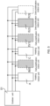
- the multi-split system shown in FIG. 1 includes one outdoor unit and six indoor units.
- the indoor unit In a case where an indoor unit needs to operate in a heating mode (for example, the heating mode of the indoor unit is turned on by a user with a remote controller, a wire controller, or a control panel on a housing of the indoor unit), the indoor unit is referred to as a heating indoor unit.
- a dehumidification indoor unit in a case where an indoor unit needs to operate in a dehumidification mode
- the indoor unit is referred to as a dehumidification indoor unit.
- the multi-split system includes at least one dehumidification indoor unit (i.e., one or more dehumidification indoor units) and at least one heating indoor unit (i.e., one or more heating indoor units)
- a refrigerant will circulate between an evaporator of the at least one dehumidification indoor unit and a condenser of the at least one heating indoor unit.
- the current heating indoor units may support the dehumidification indoor units to simultaneously operate in the dehumidification mode, with each dehumidification indoor unit having good dehumidification performance.
- the total volume of the evaporators of the dehumidification indoor units may not be matched with the total volume of the condensers of the heating indoor units (a mismatch often occurs in a case where a number of the dehumidification indoor units is greater than a number of the heating indoor units).
- the indoor units B, D, E and F enter the dehumidification mode while the indoor units A and C enter the heating mode, that is, there are four dehumidification indoor units and only two heating indoor units, and the total volume of the evaporators of the dehumidification indoor units is greater than the total volume of the condensers of the heating indoor units.
- the dehumidification indoor units need to simultaneously operate in the dehumidification mode, which will make the dehumidification performance of the dehumidification indoor units relatively poor, and even a problem that part of the dehumidification indoor units cannot perform dehumidification arises.
- the number of the dehumidification indoor units is greater than the number of the heating indoor units is described as follows.
- some rooms are used as basements.
- seasons such as transitional seasons or winter, when the humidity is large, the basements are prone to get moldy, so the basements need to be dehumidified. Therefore, a part of rooms may need to be heated, and another part of rooms may need to be dehumidified.
- the volumes of the condensers of the heating indoor units and the evaporators of the dehumidification indoor units i.e., volumes of heat exchangers used for containing the refrigerant
- the evaporators of the dehumidification indoor units are not matched in the multi-split system, for example, in a case where the number of the dehumidification indoor units is greater than the number of the heating indoor units due to a large dehumidification demand, it is possible to cause the poor dehumidification performance of the dehumidification indoor units.
- Some embodiments of the present disclosure provide a time-sharing dehumidification method for the multi-split system, in which a plurality of dehumidification indoor units are controlled to operate in the dehumidification mode at different periods. For example, in a control cycle of a time-sharing dehumidification process, the dehumidification indoor units B and D are controlled to operate in the dehumidification mode; and in another control cycle of the time-sharing dehumidification process, the dehumidification indoor units E and F are controlled to operate in the dehumidification mode.
- the total volume of evaporators of dehumidification indoor units that operate in the dehumidification mode is matched with the total volume of the condensers of the heating indoor units that operate in the heating state (for example, the total volume of the evaporators is less than or equal to the total volume of the condensers), which makes the dehumidification performance of the dehumidification indoor units that operate in the dehumidification mode good.
- the time-sharing dehumidification method for the multi-split system provided by some embodiments of the present disclosure will be described in detail below.
- the following embodiments are described by taking an example in which in the multi-split system shown in FIG. 1 , the indoor units A and C are used as the heating indoor units, and the indoor units B, D, E and F are used as the dehumidification indoor units.
- the time-sharing dehumidification method for the multi-split system includes the following steps.
- step 101 in a control cycle of the time-sharing dehumidification process, in a first collection, for dehumidification indoor units that have not performed dehumidification in the time-sharing dehumidification process: an operation mode of a first dehumidification indoor unit is set to be the dehumidification mode; a maximum number of second dehumidification indoor unit(s) that the current heating indoor units in the multi-split system are further capable of supporting besides the first dehumidification indoor unit is determined; and if there exist the second dehumidification indoor unit(s), an operation mode of each second dehumidification indoor unit is set to be the dehumidification mode.
- the first collection is composed of current dehumidification indoor units in the multi-split system.
- the time-sharing dehumidification is initiated in response to a coexistence of the dehumidification indoor units and the heating indoor unit(s) in the indoor units. In some embodiments, the time-sharing dehumidification is initiated in response to a situation that there are dehumidification indoor units and heating indoor unit(s) in the indoor units, and that the total volume of the heating indoor unit(s) is less than the total volume of the dehumidification indoor units.
- the current dehumidification indoor units refer to indoor units that need to perform the dehumidification at present in the multi-split system.
- the indoor units B, D, E and F described above are the current dehumidification indoor units, and the first collection is composed of these four dehumidification indoor units.
- the indoor units A and C are the current heating indoor units.
- the time-sharing dehumidification process refers to a process in which the indoor units B, D, E and F each operate in the dehumidification mode once.
- the process may include at least two control cycles, and any control cycle may be implemented according to the method provided by the embodiments.
- a duration of the control cycle may be a preset constant, or a time period determined according to a set rule.
- each indoor unit is a three-pipe indoor unit is taken as an example.
- one indoor heat exchanger of the indoor unit is used as an evaporator, and another indoor heat exchanger does not work; and when the indoor unit operates in the heating mode, one indoor heat exchanger of the indoor unit is used as a condenser, and another indoor heat exchanger does not work.
- the indoor unit is an indoor unit having other number of pipes.
- an indoor heat exchanger of the indoor unit is used as the condenser. It will be noted that, as shown in FIG.
- the three-pipe indoor unit may include a first indoor heat exchanger 11, a second indoor heat exchanger 12, and a first indoor electronic expansion valve 13 and a second indoor electronic expansion valve 14 that are respectively connected to the indoor heat exchangers.
- any one selected from the dehumidification indoor units that have not performed the dehumidification in the time-sharing dehumidification process may be used as the first dehumidification indoor unit.
- any one of the indoor units B, D, E and F, for example, the indoor unit B may be used as the first dehumidification indoor unit.
- a dehumidification indoor unit is determined to be the first dehumidification indoor unit according to a preset rule. For example, according to an arrangement order of all the dehumidification indoor units, the first dehumidification indoor unit is selected from the dehumidification indoor units that have not performed the dehumidification in the time-sharing dehumidification process.
- the time-sharing dehumidification method may further include step 201 shown in FIG. 3 .
- the dehumidification indoor units in the first collection are numbered.
- the dehumidification indoor units in the first collection may be numbered according to a rule of an arithmetic progression or other sorting rules.
- the dehumidification indoor units B, D, E and F may be numbered 0, 1, 2 and 3 starting from 0, respectively, and a dehumidification indoor unit with a smallest number is determined as the first dehumidification indoor unit from the dehumidification indoor units that have not performed the dehumidification in the current time-sharing dehumidification process.
- the dehumidification indoor units in the first collection are numbered according to other rules. For example, according to a sequence of twenty six letters, the dehumidification indoor units in the first collection are numbered with letters; or according to a rule of a geometric progression, the dehumidification indoor units in the first collection are numbered, which is not limited in the embodiments of the present disclosure. Given that an algorithm of the time-sharing dehumidification method is relatively simple when the dehumidification indoor units in the first collection are numbered according to the rule of the arithmetic progression, in some embodiments, the dehumidification indoor units in the first collection are numbered according to the rule of the arithmetic progression.
- the step 201 may be performed once in each time-sharing dehumidification process. Or, during a process from the multi-split system being turned on to being turned off, the step 201 may be performed once each time a distribution of the dehumidification indoor units is changed. For example, the step 201 may be performed when the number of the dehumidification indoor units is increased or reduced, or when the number of the dehumidification indoor units is unchanged, but the distribution of the dehumidification indoor units is changed (for example, the dehumidification indoor units are changed from the indoor units B, D, E and F to the indoor units B, C, E and F).
- the indoor units B, D, E and F may perform the time-sharing dehumidification once or a plurality of times.
- the operation mode of the first dehumidification indoor unit is set to be the dehumidification mode includes the following step.
- the dehumidification indoor unit with the smallest number is set as the first dehumidification indoor unit, for example, in combination with the above description, in the first control cycle of the time-sharing dehumidification process, the 0-numbered indoor unit B is set as the first dehumidification indoor unit; and the operation mode of the first dehumidification indoor unit is set to be the dehumidification mode.
- a dehumidification indoor unit with a largest number is set as the first dehumidification indoor unit.
- Some embodiments of the present disclosure are described by taking an example in which the dehumidification indoor unit with the smallest number is set as the first dehumidification indoor unit.
- the step 101 in the multi-split system, there is a further need to determine the maximum number of the second dehumidification indoor unit(s) that the current heating indoor units A and C are further capable of supporting besides the first dehumidification indoor unit.
- the second dehumidification indoor unit(s) and the first dehumidification indoor unit are consecutively numbered. That is, the numbers of the first dehumidification indoor unit and the second dehumidification indoor unit(s) are consecutively arranged according to an order from small to large.
- the second dehumidification indoor unit(s) and the first dehumidification indoor unit are consecutively numbered means that the second dehumidification indoor unit(s) are consecutively numbered, and in the control cycle, the second dehumidification indoor unit(s) and the first dehumidification indoor unit are consecutively numbered.
- the second dehumidification indoor unit(s) are determined starting from an dehumidification indoor unit subsequent to the first dehumidification indoor unit, i.e., an dehumidification indoor unit (m+1)-numbered (for example, (m+1) is equal to 1).
- the current heating indoor units A and C are further capable of supporting the indoor unit D to operate in the dehumidification mode besides the first dehumidification indoor unit (i.e., the indoor unit B), then an 1-numbered indoor unit (i.e., the indoor unit D) is set as the second dehumidification indoor unit.
- the time-sharing dehumidification method for the multi-split system further includes step 102: setting an operation mode of each remaining dehumidification indoor unit in the first collection to be a temporary non-dehumidification mode, the remaining dehumidification indoor unit being a dehumidification indoor unit that is not set to operate in the dehumidification mode in the control cycle.
- the temporary non-dehumidification mode is the opposite of the dehumidification mode.
- the temporary non-dehumidification mode refers to a mode in which the current dehumidification indoor unit does not perform the dehumidification in the current control cycle. In the control cycle, except the first dehumidification indoor unit and each second dehumidification indoor unit whose operation modes are the dehumidification mode, other dehumidification indoor unit(s) (the remaining dehumidification indoor unit(s)) have the operation modes that are the temporary non-dehumidification mode.
- the remaining dehumidification indoor unit(s) are dehumidification indoor unit(s) except the first dehumidification indoor unit and the second dehumidification indoor unit(s) in the control cycle.
- the numbers of the dehumidification indoor units that are set to operate in the dehumidification mode are 0 and 1 (i.e., the dehumidification indoor units B and D), then the numbers of the remaining dehumidification indoor units in the first control cycle are 2 and 3. That is, the dehumidification indoor units E and F are the remaining dehumidification indoor units. It is assumed that in a second control cycle, as shown in FIG.
- the serial number of the dehumidification indoor unit that is set to operate in the dehumidification mode is 2 (i.e., the dehumidification indoor unit E)
- the remaining dehumidification indoor units in the second control cycle include the 0-numbered dehumidification indoor unit, the 1-numbered dehumidification indoor unit and the 3-numbered dehumidification indoor unit. That is, the remaining dehumidification indoor units in the second control cycle include the dehumidification indoor units (numbered 0 and 1) that are set to operate in the dehumidification mode in the first control cycle and the dehumidification indoor unit (numbered 3) that has not performed the dehumidification in the time-sharing dehumidification process.
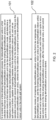
- a solid box with shadow indicates the dehumidification indoor unit which operates in the dehumidification mode in the control cycle.
- a dashed box with shadow indicates the dehumidification indoor unit which has operated in the dehumidification mode in a previous control cycle, and is in the temporary non-dehumidification mode in the current control cycle in the time-sharing dehumidification process.
- a dashed box without shadow indicates the dehumidification indoor unit which is in the temporary non-dehumidification mode in the control cycle.
- the time-sharing dehumidification method for the multi-split system provided by some embodiments of the present disclosure is briefly described by taking an example in which the time-sharing dehumidification process of the multi-split system shown in FIG. 4 includes three control cycles.
- the current dehumidification indoor units include the indoor units B, D, E and F.
- any one of the current dehumidification indoor units for example, the indoor unit B, may be set as the first dehumidification indoor unit, and the operation mode of the first dehumidification indoor unit is set to be the dehumidification mode.
- the current heating indoor units in the multi-split system are further capable of supporting the indoor unit D besides the first dehumidification indoor unit, then the indoor unit D is set as the second dehumidification indoor unit, and the operation mode of the indoor unit D is set to be the dehumidification mode.
- the operation modes of the dehumidification indoor units that are not set to operate in the dehumidification mode in the control cycle that is, the operation modes of the indoor units E and F, are set to be the temporary non-dehumidification mode.
- the operation modes of the indoor units B and D are set to be the dehumidification mode.
- the second control cycle of the current time-sharing dehumidification process starts.
- any one of the dehumidification indoor units that have not performed the dehumidification in the time-sharing dehumidification process i.e., any one of the indoor units E and F, e.g., the indoor unit E
- the operation mode of the first dehumidification indoor unit is set to be the dehumidification mode.
- the operation modes of the dehumidification indoor units that are not set to operate in the dehumidification mode in this control cycle i.e., the operation modes of the indoor units B, D and F, are set to be the temporary non-dehumidification mode.
- the operation mode of the indoor unit E is set to be the dehumidification mode.
- the dehumidification indoor unit that has not performed the dehumidification in the time-sharing dehumidification process i.e., the indoor unit F
- the indoor unit F is set as the first dehumidification indoor unit
- the operation mode of the first dehumidification indoor unit is set to be the dehumidification mode. Since the indoor unit F is a last dehumidification indoor unit that has not performed the dehumidification in the time-sharing dehumidification process, there is no second dehumidification indoor unit in the control cycle.
- the operation modes of the dehumidification indoor units that are not set to operate in the dehumidification mode in this control cycle i.e., the operation modes of the indoor units B, D and E, are set to be the temporary non-dehumidification mode.
- the operation mode of the indoor unit F is set to be the dehumidification mode.
- the time-sharing dehumidification process may be finished, or the control cycles may be cyclically performed, which is not limited in the embodiments.
- the time-sharing dehumidification method in the time-sharing dehumidification process, it may be ensured that all the current dehumidification indoor units operate in the dehumidification mode once, and it is possible to make the dehumidification performance of each dehumidification indoor unit that operates in the dehumidification mode good in each control cycle of the time-sharing dehumidification process.
- a control cycle in the time-sharing dehumidification method is described in detail in combination with FIG. 3 , and in the control cycle, the method includes the following steps after the step 201.
- step 202 in the control cycle, the m-numbered dehumidification indoor unit is set as the first dehumidification indoor unit.
- this step is described by taking an example in which in the step 201, the current dehumidification indoor units in the multi-split system shown in FIG. 4 are numbered 0, 1, 2 and 3.
- the first dehumidification indoor unit in the first control cycle of the time-sharing dehumidification process, is the 0-numbered dehumidification indoor unit (i.e., the indoor unit B, where m is equal to 0).
- the dehumidification indoor unit corresponding to the smallest serial number among the serial numbers of dehumidification indoor units that have not performed the dehumidification in the time-sharing dehumidification process is set as the first dehumidification indoor unit.
- step 203 the operation mode of the m-numbered dehumidification indoor unit is set to be the dehumidification mode. That is, the operation mode of the first dehumidification indoor unit is set to be the dehumidification mode.
- a status identifier bit (i.e., an identifier bit for indicating the operation mode) of the m-numbered dehumidification indoor unit may be set to be a first identifier (e.g., 0), which is used to represent the dehumidification mode and control the m-numbered dehumidification indoor unit to operate in the dehumidification mode.
- a first identifier e.g., 0
- this step is performed after the step 202.
- this step may be simultaneously performed with step 212.
- step 204 the operation modes of dehumidification indoor units with serial numbers less than or equal to (m - 1) (which may be expressed as ⁇ m - 1, or 0 to (m - 1)) are set to be the temporary non-dehumidification mode.
- status identifier bits of the 0-numbered dehumidification indoor unit to (m-1)-numbered dehumidification indoor unit may be set to be a second identifier (e.g., 1), which is used to represent the temporary non-dehumidification mode.
- the operation modes of these dehumidification indoor units are the temporary non-dehumidification mode.
- m is equal to 0, so there is no dehumidification indoor unit with the serial number less than or equal to (m - 1).
- m is equal to 2
- the operation modes of the dehumidification indoor units numbered 0 and 1, i.e., the operation modes of all the dehumidification indoor units that have operated in the dehumidification mode in the first control cycle are set to be the temporary non-dehumidification mode.
- This step is performed after the step 202. For example, this step may be simultaneously performed with step 213.
- step 206 it is determined whether j is less than a difference between N_total and 1 (i.e., (N_total - 1)).
- N_total is used to represent a number of the current dehumidification indoor units, i.e., a number of the dehumidification indoor units in the first collection.
- the step 206 is to determine whether the accumulated dehumidification indoor units include the last dehumidification indoor unit that has not performed the dehumidification in the time-sharing dehumidification process.
- N_total is equal to 4.
- m is equal to 3. That is, the serial number of the first dehumidification indoor unit is 3.
- j is determined to be equal to (N_total - 1). That is, the dehumidification indoor unit numbered 3 is the last dehumidification indoor unit that has not performed the dehumidification in the current time-sharing dehumidification process. Therefore, there is no need to perform the step related to determining the second dehumidification indoor unit(s). In this control cycle, only the dehumidification indoor unit numbered 3 operates in the dehumidification mode.
- step 207 is performed. If j is equal to (N_total - 1), step 214 is performed.
- the step 207 is to determine a next dehumidification indoor unit other than the first dehumidification indoor unit.
- x represents the common difference of the arithmetic progression.
- the common difference is 1 is taken for illustration.
- step 208 a volume of an evaporator of the first dehumidification indoor unit and volumes of evaporators of the dehumidification indoor unit(s) in the first collection that have not performed the dehumidification in the current time-sharing dehumidification process are accumulated in a way of accumulating one for each time, and for each time, it is determined whether the accumulation result meets: ⁇ m j DH_HP ⁇ ⁇ Heat_HP / K DH_CAP .
- ⁇ m j DH_HP represents a sum of the volume of the first dehumidification indoor unit and the volumes of the accumulated dehumidification indoor unit(s) in the first collection that have not performed the dehumidification in the current time-sharing dehumidification process;
- ⁇ Heat_HP represents a total volume of the current heating indoor unit(s) in the multi-split system;
- K DH_CAP represents a control coefficient.
- the control coefficient K DH_CAP is a ratio of the total volume of the heating indoor unit(s) to a total volume of dehumidification indoor units that can be supported.
- the control coefficient K DH_CAP may be set according to actual needs. In some embodiments, the control coefficient K DH_CAP is within a range from 1.3 to 3.0. In some embodiments, the control coefficient K DH_CAP is 1.5.
- step 209 is performed. Since the dehumidification indoor unit numbered 1 is not the last dehumidification indoor unit that has not performed the dehumidification in the time-sharing dehumidification process, the steps 207 and 208 are performed: a volume of the dehumidification indoor unit numbered 2 is further added up.
- the number of the second dehumidification indoor unit that the current heating indoor units are further capable of supporting is 1.
- step 208 it is also possible to determine whether the accumulation result meets ⁇ m j DH_HP > ⁇ Heat_HP / K DH_CAP .
- the step 209 is performed.
- the dehumidification indoor units numbered 1 and 2 should theoretically be set as the second dehumidification indoor units.
- the dehumidification indoor units numbered 0, 1 and 2 are simultaneously set to operate in the dehumidification mode.
- step 209 it is determined whether j is equal to (N_total - 1).
- the step 210 is performed. That is, the accumulation is stopped, and the accumulated dehumidification indoor unit(s) other than the first dehumidification indoor unit are set as the second dehumidification indoor unit(s). If the last dehumidification indoor unit that has not performed the dehumidification in the time-sharing dehumidification process is not accumulated, the step 207 is performed.
- step 211 it is determined whether m and n meet a condition that a sum of m and 1 is less than or equal to a difference between n and 1 (i.e., (m + 1) ⁇ (n - 1)).
- step 213 If m and n do not meet the condition (m + 1) ⁇ (n - 1), then the step 213 is performed. If m and n meet the condition (m + 1) ⁇ (n - 1) , then the serial numbers of the second dehumidification indoor unit(s) are within a range from (m + 1) to (n - 1), and the step 212 is performed.
- m and n meet the condition (m + 1) ⁇ (n - 1).
- the current heating indoor unit(s) are capable of supporting the dehumidification indoor units numbered 0 and 1 to operate in the dehumidification mode.
- the serial number of the second dehumidification indoor unit is 1.
- n 2
- j 3
- m and n do not meet the condition (m + 1) ⁇ (n - 1).
- the current heating indoor unit(s) are only capable of supporting the dehumidification indoor unit numbered 2 to operate in the dehumidification mode. In this case, there is no second dehumidification indoor unit.
- step 212 the operation modes of the dehumidification indoor unit(s) numbered from (m + 1) to (n - 1) are set to be the dehumidification mode.
- the dehumidification indoor unit(s) numbered from (m + 1) to (n - 1) are determined to be the second dehumidification indoor unit(s), and the operation modes of the second dehumidification indoor unit(s) are set to be the dehumidification mode.
- the time-sharing dehumidification method provided by some embodiments of the present disclosure, it is possible to determine a maximum number of dehumidification indoor unit(s) that the current heating indoor unit(s) are capable of supporting in the control cycle, and the operation modes of the dehumidification indoor unit(s) are set to be the dehumidification mode. In this case, it may be ensured that the dehumidification performance of each dehumidification indoor unit that operates in the dehumidification mode is good in the control cycle.
- step 214 a current operation mode is maintained.
- the operation mode of each indoor unit of the multi-split system is maintained the current operation mode.
- the operation mode of each indoor unit is maintained the current operation mode, no additional operation is needed.
- control cycle is not a last control cycle in the current time-sharing dehumidification process, then after the control cycle is finished, a next control cycle in the time-sharing dehumidification process is started.
- the process may be implemented through step 215 shown in FIG. 3 .
- control cycle is regarded as the last control cycle in the time-sharing dehumidification process.
- the time-sharing dehumidification method is based on the numbering of dehumidification indoor units in the first collection in the way of arithmetic progression.
- the method may ensure that all the current dehumidification indoor units may operate in the dehumidification mode once, and may make the dehumidification performance of each dehumidification indoor unit that operates in the dehumidification mode good in each control cycle of the time-sharing dehumidification process.
- the control cycle is the last control cycle of the time-sharing dehumidification process
- the time-sharing dehumidification process comes to an end after the current control cycle is finished.
- a plurality of time-sharing dehumidification processes usually need to be cyclically performed to make each current dehumidification indoor unit cyclically operates in the dehumidification mode. Therefore, in some embodiments, if the control cycle is the last control cycle in the time-sharing dehumidification process, after the control cycle is finished, a first control cycle of a next time-sharing dehumidification process is started.
- the serial number m is reset to be 0, so that in the first control cycle of the next time-sharing dehumidification process, the dehumidification indoor units sequentially operate in the dehumidification mode starting from the dehumidification indoor unit numbered 0.
- the dehumidification indoor units in the first collection and/or the current heating indoor unit(s) of the multi-split system are adjusted (that is, the number of the operating rooms is changed), for example, the number of the current dehumidification indoor units or the current heating indoor units is changed, or the specific indoor units used as the dehumidification indoor units or the heating indoor unit(s) in the multi-split system are changed.
- the dehumidification indoor units in the first collection and/or the current heating indoor unit(s) of the multi-split system are adjusted (that is, the number of the operating rooms is changed), for example, the number of the current dehumidification indoor units or the current heating indoor units is changed, or the specific indoor units used as the dehumidification indoor units or the heating indoor unit(s) in the multi-split system are changed.
- the indoor units A, B and D are changed to be used as the current dehumidification indoor units, and the indoor units E and F are used as the current heating indoor units, the maximum number of dehumidification indoor units that the current heating indoor units E and F are capable of supporting will also changes. In this case, if the time-sharing dehumidification process is still performed, it is impossible to make each current dehumidification indoor unit operate in the dehumidification mode once.
- the time-sharing dehumidification method provided by the embodiments of the present disclosure further includes the following step. If in the current time-sharing dehumidification process, the dehumidification indoor units in the first collection are adjusted, or the current heating indoor units are adjusted, or the dehumidification indoor units in the first collection and the current heating indoor units are all adjusted, the next time-sharing dehumidification process will be started.
- the first dehumidification indoor unit and the second dehumidification indoor unit(s) are redetermined according to the time-sharing dehumidification method described above, so that the dehumidification performance of the dehumidification indoor units that operate in the dehumidification mode in the control cycle is made good.
- the adjustment instruction is configured to cause at least one of following operations to be performed: increasing or reducing a number of the dehumidification indoor units in the first collection; or increasing or reducing a number of the current heating indoor unit(s); or changing a distribution of the dehumidification indoor units in the first collection in a case where the number of the dehumidification indoor units is not changed; or changing a distribution of the heating indoor unit(s) in a case where the number of the current heating indoor unit(s) is not changed.
- the method for determining the maximum number of the second dehumidification indoor unit(s) that the current heating indoor unit(s) in the multi-split system are further capable of supporting besides the first dehumidification indoor unit includes the following step.
- the volume of the first dehumidification indoor unit and the volumes of the dehumidification indoor units in the first collection that have not performed the dehumidification in the current time-sharing dehumidification process are accumulated one by one, until the maximum number of the second dehumidification indoor unit(s) that the current heating indoor units are further capable of supporting is determined when the accumulation result is greater than or equal to a reference threshold.
- the accumulated dehumidification indoor unit(s) other than the first dehumidification indoor unit are set as the second dehumidification indoor unit(s).
- the reference threshold is a ratio of a total volume of the current heating indoor unit(s) in the multi-split system to the control coefficient K DH_CAP .
- the reference threshold is the above [ ⁇ Heat_HP]/K DH_CAP , i.e., the ratio of the total volume of the current heating indoor unit(s) in the multi-split system to the control coefficient K DH_CAP . Since the specific processes of the steps 206 to 209 have been described in detail in the foregoing embodiments, details will not be repeated here again.
- the first dehumidification indoor unit and the second dehumidification indoor unit(s) are determined through being numbered.
- the first dehumidification indoor unit and the second dehumidification indoor unit(s) be determined without the above numbering method.
- the volume of the first dehumidification indoor unit and the volumes of the dehumidification indoor units in the first collection that have not performed the dehumidification in the current time-sharing dehumidification process may be accumulated one by one through pointers, so as to determine the second dehumidification indoor unit(s).
- the foregoing programs may be stored in a computer readable storage medium, and when executed by a processor, the computer programs implement the time-sharing dehumidification method of the multi-split system described above. When the programs are executed, the steps including the embodiments of the above method are performed.
- the above storage medium includes a read only memory (ROM), a random access memory (RAM), a magnetic disk, an optical disk or other media that is able to store program codes.
- the dehumidification indoor unit includes a first indoor electronic expansion valve that is not located on a dehumidification loop and a second indoor electronic expansion valve that is located on the dehumidification loop.
- the multi-split system includes an outdoor unit 01, an indoor unit 02 and an indoor unit 03.
- the indoor unit 02 is the heating indoor unit
- the indoor unit 03 is the dehumidification indoor unit.
- a first indoor heat exchanger 11 and a first indoor electronic expansion valve 13 of the indoor unit 03 are not located on the dehumidification loop
- a second indoor heat exchanger 12 and a second indoor electronic expansion valve 14 of the indoor unit 03 are located on the dehumidification loop.
- the first indoor electronic expansion valve is located on a pipe between the dehumidification loop and the first indoor heat exchanger, and the second indoor electronic expansion valve and the second indoor heat exchanger are sequentially located on the dehumidification loop.
- the multi-split system shown in FIG. 7 is illustrated by it including one dehumidification indoor unit and one heating indoor unit.
- the structure of each indoor unit may be the same as the structure of the above heating indoor unit 02 or the above dehumidification indoor unit 03.
- the operation mode of the dehumidification indoor unit 03 is set to be the dehumidification mode includes the following steps.
- the first indoor electronic expansion valve 13 of the dehumidification indoor unit 03 is in a closed state to make the first indoor heat exchanger 11 not work.
- SH is used to represent a difference between a temperature of an air pipe 16 and a temperature of a liquid pipe 15 of the dehumidification indoor unit
- SHo is used to represent a target degree of evaporation superheat.
- the second indoor heat exchanger 12 of the dehumidification indoor unit 03 may be used as an evaporator for dehumidification.
- the initial value EVR(0) may be set according to actual needs. In some embodiments, the initial value EVR(0) is within a range from 100 puls to 150 puls.
- the target degree of evaporation superheat SHo may be a preset value, or may be determined according to a relative humidity of return air of the dehumidification indoor unit 03, a humidity set by a user, the temperature of the liquid pipe of the dehumidification indoor unit and a temperature of the return air of the dehumidification indoor unit.
- the target degree of evaporation superheat SHo may be determined according to Table 1.
- Table 1 ⁇ H SHo ⁇ H ⁇ -10% (Ti - Tlp) + 4 -10% ⁇ ⁇ H ⁇ 0 (Ti - Tlp) 0 ⁇ ⁇ H ⁇ 10% 3 ⁇ (Ti - Tlp) + 4 10% ⁇ ⁇ H ⁇ 20% (Ti - Tlp) / 2 20% ⁇ ⁇ H 3
- Hi is used to represent the relative humidity of the return air of the dehumidification indoor unit
- Hs is used to represent the humidity set by the user
- Ti is used to represent the temperature of the return air of the dehumidification indoor unit
- Tip is used to represent the temperature of the liquid pipe 15 of the dehumidification indoor unit 02.
- the relative humidity of the return air refers to a relative humidity at a position of the dehumidification indoor unit where the air returns.
- the embodiments of the present disclosure provide a method for controlling opening degrees of the first indoor electronic expansion valve 13 that is not located on the dehumidification loop and the second indoor electronic expansion valve 14 that is located on the dehumidification loop in the dehumidification indoor unit in each control cycle in the time-sharing dehumidification process, so as to ensure that the dehumidification performance of the dehumidification indoor units in each control cycle is good.
- the operation mode of the dehumidification indoor unit 03 is set to be the temporary non-dehumidification mode includes: the first indoor electronic expansion valve 13 and the second indoor electronic expansion valve 14 of the dehumidification indoor unit 03 being in a fully closed state.
- the operation mode of the heating indoor unit(s) is the heating mode.
- a second indoor electronic expansion valve 14' of the heating indoor unit is in a fully closed state, so that a second indoor heat exchanger 12' does not work; and a first indoor electronic expansion valve 13' is in a fully open state, so that a first indoor heat exchanger 11' is used as the condenser for heating.
- the first dehumidification indoor unit and the maximum number of the second dehumidification indoor unit(s) that the current heating indoor unit(s) are further capable of supporting are determined, and the operation mode of the first dehumidification indoor unit is set to be the dehumidification mode.
- the operation modes of the second dehumidification indoor unit(s) are set to be the dehumidification mode, and the dehumidification indoor units that are not set to operate in the dehumidification mode in the current control cycle are set to be in the temporary non-dehumidification mode. If the current control cycle is not the last control cycle in the current time-sharing dehumidification process, the next control cycle in the current time-sharing dehumidification process is started after the current control cycle is finished.
- the time-sharing dehumidification process it may be ensured that all the current dehumidification indoor units may operate in the dehumidification mode once, and it may also be ensured that the current heating indoor unit(s) are capable of supporting the first dehumidification indoor unit and the second dehumidification indoor unit(s) in each control cycle to operate in the dehumidification mode.
- the dehumidification performance of each dehumidification indoor unit that operates in the dehumidification mode in each control cycle is good.
- Some embodiments of the present disclosure further provide a multi-split system including a memory and a processor.
- the memory stores computer programs capable of running on the processor, and the processor is configured to execute the computer programs to make the multi-split system implement the following steps.
- at least one of a plurality of dehumidification indoor units operates in the dehumidification mode, so that the sum of the volume of the evaporator of the at least one dehumidification indoor unit is matched with the sum of the volume(s) of the condenser(s) of the current heating indoor unit(s).
- the at least one dehumidification indoor unit stops operating in the dehumidification mode, and another at least one dehumidification indoor unit operates in the dehumidification mode; and a total volume of the evaporator of the another at least one dehumidification indoor unit is matched with the total volume of the condenser(s) of the current heating indoor unit(s).
- the steps are cyclically performed in this way, so that in the time-sharing dehumidification process, each of the plurality of dehumidification indoor units operates in the dehumidification mode once.
- the processor of the multi-split system may achieve a plurality of logical functions, and the processor may be divided into different functional modules according to the logical functions realized by the processor. As shown in FIG. 8 , after the processor is divided into different functional modules, the processor includes a control module 10 and a determination module 20.
- the control module 10 is configured to set the operation mode of the first dehumidification indoor unit to be the dehumidification mode in the control cycle of the time-sharing dehumidification process for the dehumidification indoor unit(s) in the first collection that have not performed the dehumidification in the time-sharing dehumidification process.
- the first collection is composed of the current dehumidification indoor units in the multi-split system.
- the determination module is used to determine the maximum number of the second dehumidification indoor unit(s) that the current heating indoor unit(s) in the multi-split system are further capable of supporting besides the first dehumidification indoor unit.
- control module 10 is further configured to set the operation mode of each second dehumidification indoor unit to be the dehumidification mode when there exist the second dehumidification unit(s).
- the control module 10 is further configured to set the operation modes of the remaining dehumidification indoor units in the first collection to be the temporary non-dehumidification mode.
- the remaining dehumidification indoor units are the dehumidification indoor units that are not set to operate in the dehumidification mode in the control cycle.
- control module 10 is further configured to control the next control cycle in the current time-sharing dehumidification process to be started after the current control cycle is finished.
- control module 10 is further configured to control the next time-sharing dehumidification process to be started.
- the determination module 20 includes an accumulation module and a comparison module.
- the accumulation module is configured to accumulate the volume of the first dehumidification indoor unit and the volume(s) of the dehumidification indoor unit(s) in the first collection that have not performed the dehumidification in the time-sharing dehumidification process one by one.
- the comparison module is configured to compare the accumulation result with the reference threshold, until the determination module 20 determines the maximum number of the second dehumidification indoor unit(s) that the current heating indoor units may further capable of supporting when accumulation result is less than or equal to the reference threshold.
- the accumulation result is still less than the reference threshold when the last dehumidification indoor unit that has not performed the dehumidification in the time-sharing dehumidification process is accumulated by the accumulation module, then the accumulated dehumidification indoor unit(s) other than the first dehumidification indoor unit is used as the second dehumidification indoor unit(s).
- the reference threshold is the ratio of the total volume of the current heating indoor units in the multi-split system to the control coefficient.
- the multi-split system provided by some embodiments of the present disclosure further includes a numbering module 30 which is configured to number the dehumidification indoor units in the first collection according to the rule of the arithmetic progression.
- the control module 10 may be configured to take the dehumidification indoor unit with the smallest serial number or the largest serial number as the first dehumidification indoor unit, and set the operation mode of the first dehumidification indoor unit to be the dehumidification mode.
- the determination module 20 is configured to determine the maximum number of the second dehumidification indoor unit(s) that the current heating indoor unit(s) in the multi-split system are further capable of supporting besides the first dehumidification indoor unit.
- the second dehumidification indoor unit(s) and the first dehumidification indoor unit are consecutively numbered.
- the dehumidification indoor unit includes the first indoor electronic expansion valve that is not located on the dehumidification loop, and the second indoor electronic expansion valve that is located on the dehumidification loop.
- the multi-split system further includes an opening degree control module.
- control module 10 set the operation mode of the dehumidification indoor unit to be the dehumidification mode includes the following step.
- the control module 10 is configured to control the first indoor electronic expansion valve of the dehumidification indoor unit to be in the closed state.
- the initial value EVR(0) of the opening degree of the second indoor electronic expansion valve is the preset value.
- SH is used to represent the difference value between the temperature of the air pipe and the temperature of the liquid pipe of the dehumidification indoor unit
- SHo is used to represent the target degree of evaporation superheat.
- the target degree of evaporation superheat SHo may be determined according to the Table 1 described above, and details will not be repeated again in the embodiments of the present disclosure.
- each module in the embodiments may be a processor provided independently, or may be integrated in a certain processor of the multi-split system, or may be stored in the memory of the multi-split system in a form of program code and called by a certain processor of the multi-split system to perform the function of each module described above.
- the processor described herein may be a central processing unit (CPU), a graphics processing unit (GPU), or an application specific integrated circuit (ASIC), or one or more integrated circuits configured to implement the embodiments of the present disclosure.
- the multi-split system may include a control board in the multi-split system.
- the control board may include an indoor unit control board and a general control board communicatively connected to the indoor unit control board.
- the indoor unit control board may be disposed in each indoor unit, and the general control board may be disposed in the outdoor unit of the multi-split system.
- the general control board may determine the first dehumidification indoor unit and the second dehumidification indoor unit(s) that may be set to operate in the dehumidification mode in a control cycle in the time-sharing dehumidification process, and notify the indoor unit control boards to control the first dehumidification indoor unit and the second dehumidification indoor unit(s) to operate in the dehumidification mode, and to control the operation modes of the remaining dehumidification indoor unit(s) to be the temporary non-dehumidification mode.
- some embodiments of the present disclosure provide a multi-split system to which the time-sharing dehumidification method of the multi-split system described above is applied, and the multi-split system has same beneficial effects as the time-sharing dehumidification method for the multi-split system.
- Some embodiments of the present disclosure provide a computer storage medium storing computer instructions that, when executed by a time-sharing dehumidification device of the multi-split system, cause the time-sharing dehumidification device to perform the time-sharing dehumidification method for the multi-split system.
- the computer storage medium has the same beneficial effects as the time-sharing dehumidification method for the multi-split system provided by the foregoing embodiments. Since the beneficial effects of the time-sharing dehumidification method for the multi-split system have been described in detail in the foregoing embodiments, detains will not be repeated again herein.
- the computer storage medium may include the ROM, the RAM, the magnetic disk, the optical disk or other media that is capable of storing program codes.
Landscapes
- Engineering & Computer Science (AREA)
- Mechanical Engineering (AREA)
- General Engineering & Computer Science (AREA)
- Chemical & Material Sciences (AREA)
- Combustion & Propulsion (AREA)
- Signal Processing (AREA)
- Physics & Mathematics (AREA)
- Fuzzy Systems (AREA)
- Mathematical Physics (AREA)
- Human Computer Interaction (AREA)
- Thermal Sciences (AREA)
- Air Conditioning Control Device (AREA)
- Drying Of Gases (AREA)
Applications Claiming Priority (2)
| Application Number | Priority Date | Filing Date | Title |
|---|---|---|---|
| CN201810233694.1A CN108758960B (zh) | 2018-03-21 | 2018-03-21 | 多联机系统的分时除湿方法和装置、计算机存储介质 |
| PCT/CN2019/078914 WO2019179474A1 (zh) | 2018-03-21 | 2019-03-20 | 多联机系统及其分时除湿方法 |
Publications (3)
| Publication Number | Publication Date |
|---|---|
| EP3770519A1 EP3770519A1 (en) | 2021-01-27 |
| EP3770519A4 EP3770519A4 (en) | 2021-12-29 |
| EP3770519B1 true EP3770519B1 (en) | 2024-07-17 |
Family
ID=63980570
Family Applications (1)
| Application Number | Title | Priority Date | Filing Date |
|---|---|---|---|
| EP19772449.5A Active EP3770519B1 (en) | 2018-03-21 | 2019-03-20 | Multi-split system and time-sharing dehumidification method therefor |
Country Status (4)
| Country | Link |
|---|---|
| EP (1) | EP3770519B1 (pl) |
| CN (1) | CN108758960B (pl) |
| PL (1) | PL3770519T3 (pl) |
| WO (1) | WO2019179474A1 (pl) |
Families Citing this family (4)
| Publication number | Priority date | Publication date | Assignee | Title |
|---|---|---|---|---|
| CN108758960B (zh) * | 2018-03-21 | 2020-02-04 | 青岛海信日立空调系统有限公司 | 多联机系统的分时除湿方法和装置、计算机存储介质 |
| CN111023478B (zh) * | 2019-12-26 | 2021-12-03 | 广州华凌制冷设备有限公司 | 空调器控制方法、装置、空调器和存储介质 |
| CN111174394A (zh) * | 2020-01-02 | 2020-05-19 | 珠海格力电器股份有限公司 | 一种水多联空调及其控制方法、装置和存储介质 |
| CN114353276B (zh) * | 2020-10-13 | 2023-03-28 | 美的集团武汉制冷设备有限公司 | 多联机及其控制方法、计算机存储介质 |
Family Cites Families (16)
| Publication number | Priority date | Publication date | Assignee | Title |
|---|---|---|---|---|
| CN2161858Y (zh) * | 1993-08-16 | 1994-04-13 | 张良 | 分时切换式微型中央空调机 |
| JPH07332795A (ja) * | 1994-06-02 | 1995-12-22 | Matsushita Seiko Co Ltd | 多室型空気調和装置 |
| JPH08189690A (ja) * | 1995-01-13 | 1996-07-23 | Matsushita Electric Ind Co Ltd | 多室形空気調和システムの暖房除湿運転制御装置 |
| JP3137114B1 (ja) * | 1999-10-06 | 2001-02-19 | 松下電器産業株式会社 | 多室形空気調和装置 |
| CN1202387C (zh) * | 2003-01-27 | 2005-05-18 | 广东科龙电器股份有限公司 | 一种一拖三空调器及其变频控制方法 |
| JP2005016782A (ja) * | 2003-06-24 | 2005-01-20 | Matsushita Electric Ind Co Ltd | 多室空気調和機の膨張弁制御方法 |
| CN100504196C (zh) * | 2006-09-21 | 2009-06-24 | 海尔集团公司 | 健康除湿空调器 |
| KR100854829B1 (ko) * | 2007-02-13 | 2008-08-27 | 엘지전자 주식회사 | 공기조화 시스템 및 그 제어방법 |
| JP2011052847A (ja) * | 2009-08-31 | 2011-03-17 | Panasonic Corp | 多室型空気調和装置 |
| CN102878613B (zh) * | 2012-09-20 | 2015-09-02 | 青岛海信日立空调系统有限公司 | 控制多联机空调系统中温湿度的方法及多联机空调系统 |
| CN202902496U (zh) * | 2012-10-31 | 2013-04-24 | 青岛海信日立空调系统有限公司 | 多联机热泵空调系统 |
| CN103062851B (zh) * | 2013-01-07 | 2015-12-09 | 青岛海信日立空调系统有限公司 | 空调系统及其除湿方法 |
| CN103353147B (zh) * | 2013-06-28 | 2016-05-25 | 青岛海信日立空调系统有限公司 | 三管制全热处理多联机空调系统及温湿度独立控制方法 |
| CN104633771B (zh) * | 2013-11-13 | 2018-07-03 | 珠海格力电器股份有限公司 | 多联式空调机组及其控制方法 |
| CN203964187U (zh) * | 2014-07-21 | 2014-11-26 | 深圳市沃森空调技术有限公司 | 可同时制冷制热的多联式空调器 |
| CN108758960B (zh) * | 2018-03-21 | 2020-02-04 | 青岛海信日立空调系统有限公司 | 多联机系统的分时除湿方法和装置、计算机存储介质 |
-
2018
- 2018-03-21 CN CN201810233694.1A patent/CN108758960B/zh active Active
-
2019
- 2019-03-20 EP EP19772449.5A patent/EP3770519B1/en active Active
- 2019-03-20 PL PL19772449.5T patent/PL3770519T3/pl unknown
- 2019-03-20 WO PCT/CN2019/078914 patent/WO2019179474A1/zh not_active Ceased
Also Published As
| Publication number | Publication date |
|---|---|
| PL3770519T3 (pl) | 2024-11-25 |
| WO2019179474A1 (zh) | 2019-09-26 |
| EP3770519A1 (en) | 2021-01-27 |
| CN108758960A (zh) | 2018-11-06 |
| EP3770519A4 (en) | 2021-12-29 |
| CN108758960B (zh) | 2020-02-04 |
Similar Documents
| Publication | Publication Date | Title |
|---|---|---|
| JP6642379B2 (ja) | 空調機 | |
| EP3770519A1 (en) | Multi-split system and time-sharing dehumidification method therefor | |
| CN115264643B (zh) | 一种空调系统及其控制方法 | |
| CN110671744B (zh) | 一种空调器及其恒温除湿的控制方法 | |
| CN111059709A (zh) | 一种空调器的控制方法及空调器 | |
| CN110094857A (zh) | 空调电子膨胀阀的控制方法、装置、计算机产品及空调 | |
| CN108895567A (zh) | 室外机、多联机系统及控制方法、装置、计算机存储介质 | |
| US6922613B2 (en) | Method for operating multi-type air conditioner | |
| CN111076352A (zh) | 多联机电子膨胀阀的控制方法、装置、空调器及存储介质 | |
| EP4220028A1 (en) | Multi-split air conditioner and control method therefor, and computer storage medium | |
| JP5403093B2 (ja) | 空気調和装置 | |
| CN113864975A (zh) | 变频空调的低温制冷控制方法、装置和空调 | |
| CN112856748B (zh) | 冷量输出控制方法、装置、机房空调和存储介质 | |
| JP5082807B2 (ja) | 空気調和装置 | |
| EP3627075A2 (en) | Method and apparatus for re-heat circuit operation | |
| WO2015173897A1 (ja) | 空気調和機及び空気調和システム | |
| US20220307755A1 (en) | Control scheme for automatic fan mode for use with variable refrigerant flow systems | |
| CN114135973B (zh) | 一种多联机控制方法、装置及多联机 | |
| CN120466803A (zh) | 空气调节系统及其控制方法、装置、电子设备及存储介质 | |
| CN114576811B (zh) | 一拖多空调及其控制方法、控制装置和可读存储介质 | |
| CN108562021A (zh) | 一种空调室内机的除湿控制方法及装置、空调器 | |
| CN110762792B (zh) | 一种空调器的控制方法及空调器 | |
| CN212278706U (zh) | 一种恒温除湿制冷装置 | |
| CN115247878A (zh) | 用于控制空调器的方法及装置、空调器、存储介质 | |
| US20210190396A1 (en) | Method and apparatus for hybrid dehumidification |
Legal Events
| Date | Code | Title | Description |
|---|---|---|---|
| STAA | Information on the status of an ep patent application or granted ep patent |
Free format text: STATUS: THE INTERNATIONAL PUBLICATION HAS BEEN MADE |
|
| PUAI | Public reference made under article 153(3) epc to a published international application that has entered the european phase |
Free format text: ORIGINAL CODE: 0009012 |
|
| STAA | Information on the status of an ep patent application or granted ep patent |
Free format text: STATUS: REQUEST FOR EXAMINATION WAS MADE |
|
| 17P | Request for examination filed |
Effective date: 20200819 |
|
| AK | Designated contracting states |
Kind code of ref document: A1 Designated state(s): AL AT BE BG CH CY CZ DE DK EE ES FI FR GB GR HR HU IE IS IT LI LT LU LV MC MK MT NL NO PL PT RO RS SE SI SK SM TR |
|
| AX | Request for extension of the european patent |
Extension state: BA ME |
|
| DAV | Request for validation of the european patent (deleted) | ||
| DAX | Request for extension of the european patent (deleted) | ||
| A4 | Supplementary search report drawn up and despatched |
Effective date: 20211129 |
|
| RIC1 | Information provided on ipc code assigned before grant |
Ipc: F25B 13/00 20060101ALI20211123BHEP Ipc: F24F 3/14 20060101ALI20211123BHEP Ipc: F24F 3/06 20060101ALI20211123BHEP Ipc: F24F 11/65 20180101ALI20211123BHEP Ipc: F24F 11/61 20180101ALI20211123BHEP Ipc: F24F 11/30 20180101AFI20211123BHEP |
|
| GRAP | Despatch of communication of intention to grant a patent |
Free format text: ORIGINAL CODE: EPIDOSNIGR1 |
|
| STAA | Information on the status of an ep patent application or granted ep patent |
Free format text: STATUS: GRANT OF PATENT IS INTENDED |
|
| INTG | Intention to grant announced |
Effective date: 20240207 |
|
| GRAS | Grant fee paid |
Free format text: ORIGINAL CODE: EPIDOSNIGR3 |
|
| GRAA | (expected) grant |
Free format text: ORIGINAL CODE: 0009210 |
|
| STAA | Information on the status of an ep patent application or granted ep patent |
Free format text: STATUS: THE PATENT HAS BEEN GRANTED |
|
| AK | Designated contracting states |
Kind code of ref document: B1 Designated state(s): AL AT BE BG CH CY CZ DE DK EE ES FI FR GB GR HR HU IE IS IT LI LT LU LV MC MK MT NL NO PL PT RO RS SE SI SK SM TR |
|
| RAP3 | Party data changed (applicant data changed or rights of an application transferred) |
Owner name: QINGDAO HISENSE HITACHI AIR-CONDITIONING SYSTEMSCO., LTD. |
|
| REG | Reference to a national code |
Ref country code: CH Ref legal event code: EP |
|
| REG | Reference to a national code |
Ref country code: DE Ref legal event code: R096 Ref document number: 602019055392 Country of ref document: DE |
|
| REG | Reference to a national code |
Ref country code: IE Ref legal event code: FG4D |
|
| REG | Reference to a national code |
Ref country code: LT Ref legal event code: MG9D |
|
| REG | Reference to a national code |
Ref country code: NL Ref legal event code: MP Effective date: 20240717 |
|
| PG25 | Lapsed in a contracting state [announced via postgrant information from national office to epo] |
Ref country code: PT Free format text: LAPSE BECAUSE OF FAILURE TO SUBMIT A TRANSLATION OF THE DESCRIPTION OR TO PAY THE FEE WITHIN THE PRESCRIBED TIME-LIMIT Effective date: 20241118 |
|
| REG | Reference to a national code |
Ref country code: AT Ref legal event code: MK05 Ref document number: 1704480 Country of ref document: AT Kind code of ref document: T Effective date: 20240717 |
|
| PG25 | Lapsed in a contracting state [announced via postgrant information from national office to epo] |
Ref country code: NL Free format text: LAPSE BECAUSE OF FAILURE TO SUBMIT A TRANSLATION OF THE DESCRIPTION OR TO PAY THE FEE WITHIN THE PRESCRIBED TIME-LIMIT Effective date: 20240717 |
|
| PG25 | Lapsed in a contracting state [announced via postgrant information from national office to epo] |
Ref country code: PT Free format text: LAPSE BECAUSE OF FAILURE TO SUBMIT A TRANSLATION OF THE DESCRIPTION OR TO PAY THE FEE WITHIN THE PRESCRIBED TIME-LIMIT Effective date: 20241118 Ref country code: NL Free format text: LAPSE BECAUSE OF FAILURE TO SUBMIT A TRANSLATION OF THE DESCRIPTION OR TO PAY THE FEE WITHIN THE PRESCRIBED TIME-LIMIT Effective date: 20240717 |
|
| PG25 | Lapsed in a contracting state [announced via postgrant information from national office to epo] |
Ref country code: NO Free format text: LAPSE BECAUSE OF FAILURE TO SUBMIT A TRANSLATION OF THE DESCRIPTION OR TO PAY THE FEE WITHIN THE PRESCRIBED TIME-LIMIT Effective date: 20241017 |
|
| PG25 | Lapsed in a contracting state [announced via postgrant information from national office to epo] |
Ref country code: FI Free format text: LAPSE BECAUSE OF FAILURE TO SUBMIT A TRANSLATION OF THE DESCRIPTION OR TO PAY THE FEE WITHIN THE PRESCRIBED TIME-LIMIT Effective date: 20240717 Ref country code: GR Free format text: LAPSE BECAUSE OF FAILURE TO SUBMIT A TRANSLATION OF THE DESCRIPTION OR TO PAY THE FEE WITHIN THE PRESCRIBED TIME-LIMIT Effective date: 20241018 |
|
| PG25 | Lapsed in a contracting state [announced via postgrant information from national office to epo] |
Ref country code: BG Free format text: LAPSE BECAUSE OF FAILURE TO SUBMIT A TRANSLATION OF THE DESCRIPTION OR TO PAY THE FEE WITHIN THE PRESCRIBED TIME-LIMIT Effective date: 20240717 |
|
| PG25 | Lapsed in a contracting state [announced via postgrant information from national office to epo] |
Ref country code: LV Free format text: LAPSE BECAUSE OF FAILURE TO SUBMIT A TRANSLATION OF THE DESCRIPTION OR TO PAY THE FEE WITHIN THE PRESCRIBED TIME-LIMIT Effective date: 20240717 |
|
| PG25 | Lapsed in a contracting state [announced via postgrant information from national office to epo] |
Ref country code: IS Free format text: LAPSE BECAUSE OF FAILURE TO SUBMIT A TRANSLATION OF THE DESCRIPTION OR TO PAY THE FEE WITHIN THE PRESCRIBED TIME-LIMIT Effective date: 20241117 Ref country code: AT Free format text: LAPSE BECAUSE OF FAILURE TO SUBMIT A TRANSLATION OF THE DESCRIPTION OR TO PAY THE FEE WITHIN THE PRESCRIBED TIME-LIMIT Effective date: 20240717 |
|
| PG25 | Lapsed in a contracting state [announced via postgrant information from national office to epo] |
Ref country code: HR Free format text: LAPSE BECAUSE OF FAILURE TO SUBMIT A TRANSLATION OF THE DESCRIPTION OR TO PAY THE FEE WITHIN THE PRESCRIBED TIME-LIMIT Effective date: 20240717 |
|
| PG25 | Lapsed in a contracting state [announced via postgrant information from national office to epo] |
Ref country code: ES Free format text: LAPSE BECAUSE OF FAILURE TO SUBMIT A TRANSLATION OF THE DESCRIPTION OR TO PAY THE FEE WITHIN THE PRESCRIBED TIME-LIMIT Effective date: 20240717 Ref country code: RS Free format text: LAPSE BECAUSE OF FAILURE TO SUBMIT A TRANSLATION OF THE DESCRIPTION OR TO PAY THE FEE WITHIN THE PRESCRIBED TIME-LIMIT Effective date: 20241017 |
|
| PG25 | Lapsed in a contracting state [announced via postgrant information from national office to epo] |
Ref country code: RS Free format text: LAPSE BECAUSE OF FAILURE TO SUBMIT A TRANSLATION OF THE DESCRIPTION OR TO PAY THE FEE WITHIN THE PRESCRIBED TIME-LIMIT Effective date: 20241017 Ref country code: NO Free format text: LAPSE BECAUSE OF FAILURE TO SUBMIT A TRANSLATION OF THE DESCRIPTION OR TO PAY THE FEE WITHIN THE PRESCRIBED TIME-LIMIT Effective date: 20241017 Ref country code: LV Free format text: LAPSE BECAUSE OF FAILURE TO SUBMIT A TRANSLATION OF THE DESCRIPTION OR TO PAY THE FEE WITHIN THE PRESCRIBED TIME-LIMIT Effective date: 20240717 Ref country code: IS Free format text: LAPSE BECAUSE OF FAILURE TO SUBMIT A TRANSLATION OF THE DESCRIPTION OR TO PAY THE FEE WITHIN THE PRESCRIBED TIME-LIMIT Effective date: 20241117 Ref country code: HR Free format text: LAPSE BECAUSE OF FAILURE TO SUBMIT A TRANSLATION OF THE DESCRIPTION OR TO PAY THE FEE WITHIN THE PRESCRIBED TIME-LIMIT Effective date: 20240717 Ref country code: GR Free format text: LAPSE BECAUSE OF FAILURE TO SUBMIT A TRANSLATION OF THE DESCRIPTION OR TO PAY THE FEE WITHIN THE PRESCRIBED TIME-LIMIT Effective date: 20241018 Ref country code: FI Free format text: LAPSE BECAUSE OF FAILURE TO SUBMIT A TRANSLATION OF THE DESCRIPTION OR TO PAY THE FEE WITHIN THE PRESCRIBED TIME-LIMIT Effective date: 20240717 Ref country code: ES Free format text: LAPSE BECAUSE OF FAILURE TO SUBMIT A TRANSLATION OF THE DESCRIPTION OR TO PAY THE FEE WITHIN THE PRESCRIBED TIME-LIMIT Effective date: 20240717 Ref country code: BG Free format text: LAPSE BECAUSE OF FAILURE TO SUBMIT A TRANSLATION OF THE DESCRIPTION OR TO PAY THE FEE WITHIN THE PRESCRIBED TIME-LIMIT Effective date: 20240717 Ref country code: AT Free format text: LAPSE BECAUSE OF FAILURE TO SUBMIT A TRANSLATION OF THE DESCRIPTION OR TO PAY THE FEE WITHIN THE PRESCRIBED TIME-LIMIT Effective date: 20240717 |
|
| PG25 | Lapsed in a contracting state [announced via postgrant information from national office to epo] |
Ref country code: SM Free format text: LAPSE BECAUSE OF FAILURE TO SUBMIT A TRANSLATION OF THE DESCRIPTION OR TO PAY THE FEE WITHIN THE PRESCRIBED TIME-LIMIT Effective date: 20240717 Ref country code: DK Free format text: LAPSE BECAUSE OF FAILURE TO SUBMIT A TRANSLATION OF THE DESCRIPTION OR TO PAY THE FEE WITHIN THE PRESCRIBED TIME-LIMIT Effective date: 20240717 Ref country code: RO Free format text: LAPSE BECAUSE OF FAILURE TO SUBMIT A TRANSLATION OF THE DESCRIPTION OR TO PAY THE FEE WITHIN THE PRESCRIBED TIME-LIMIT Effective date: 20240717 |
|
| REG | Reference to a national code |
Ref country code: DE Ref legal event code: R097 Ref document number: 602019055392 Country of ref document: DE |
|
| PG25 | Lapsed in a contracting state [announced via postgrant information from national office to epo] |
Ref country code: EE Free format text: LAPSE BECAUSE OF FAILURE TO SUBMIT A TRANSLATION OF THE DESCRIPTION OR TO PAY THE FEE WITHIN THE PRESCRIBED TIME-LIMIT Effective date: 20240717 |
|
| PG25 | Lapsed in a contracting state [announced via postgrant information from national office to epo] |
Ref country code: CZ Free format text: LAPSE BECAUSE OF FAILURE TO SUBMIT A TRANSLATION OF THE DESCRIPTION OR TO PAY THE FEE WITHIN THE PRESCRIBED TIME-LIMIT Effective date: 20240717 |
|
| PG25 | Lapsed in a contracting state [announced via postgrant information from national office to epo] |
Ref country code: SK Free format text: LAPSE BECAUSE OF FAILURE TO SUBMIT A TRANSLATION OF THE DESCRIPTION OR TO PAY THE FEE WITHIN THE PRESCRIBED TIME-LIMIT Effective date: 20240717 |
|
| PLBE | No opposition filed within time limit |
Free format text: ORIGINAL CODE: 0009261 |
|
| STAA | Information on the status of an ep patent application or granted ep patent |
Free format text: STATUS: NO OPPOSITION FILED WITHIN TIME LIMIT |
|
| 26N | No opposition filed |
Effective date: 20250422 |
|
| PG25 | Lapsed in a contracting state [announced via postgrant information from national office to epo] |
Ref country code: SE Free format text: LAPSE BECAUSE OF FAILURE TO SUBMIT A TRANSLATION OF THE DESCRIPTION OR TO PAY THE FEE WITHIN THE PRESCRIBED TIME-LIMIT Effective date: 20240717 |
|
| PG25 | Lapsed in a contracting state [announced via postgrant information from national office to epo] |
Ref country code: MC Free format text: LAPSE BECAUSE OF FAILURE TO SUBMIT A TRANSLATION OF THE DESCRIPTION OR TO PAY THE FEE WITHIN THE PRESCRIBED TIME-LIMIT Effective date: 20240717 |
|
| REG | Reference to a national code |
Ref country code: CH Ref legal event code: H13 Free format text: ST27 STATUS EVENT CODE: U-0-0-H10-H13 (AS PROVIDED BY THE NATIONAL OFFICE) Effective date: 20251024 |
|
| PG25 | Lapsed in a contracting state [announced via postgrant information from national office to epo] |
Ref country code: LU Free format text: LAPSE BECAUSE OF NON-PAYMENT OF DUE FEES Effective date: 20250320 |
|
| REG | Reference to a national code |
Ref country code: BE Ref legal event code: MM Effective date: 20250331 |
|
| PG25 | Lapsed in a contracting state [announced via postgrant information from national office to epo] |
Ref country code: BE Free format text: LAPSE BECAUSE OF NON-PAYMENT OF DUE FEES Effective date: 20250331 |
|
| PG25 | Lapsed in a contracting state [announced via postgrant information from national office to epo] |
Ref country code: CH Free format text: LAPSE BECAUSE OF NON-PAYMENT OF DUE FEES Effective date: 20250331 |
|
| PG25 | Lapsed in a contracting state [announced via postgrant information from national office to epo] |
Ref country code: IE Free format text: LAPSE BECAUSE OF NON-PAYMENT OF DUE FEES Effective date: 20250320 |
|
| PG25 | Lapsed in a contracting state [announced via postgrant information from national office to epo] |
Ref country code: IT Free format text: LAPSE BECAUSE OF FAILURE TO SUBMIT A TRANSLATION OF THE DESCRIPTION OR TO PAY THE FEE WITHIN THE PRESCRIBED TIME-LIMIT Effective date: 20240717 |
|
| PGFP | Annual fee paid to national office [announced via postgrant information from national office to epo] |
Ref country code: GB Payment date: 20260324 Year of fee payment: 8 |
|
| PGFP | Annual fee paid to national office [announced via postgrant information from national office to epo] |
Ref country code: DE Payment date: 20260319 Year of fee payment: 8 |
|
| PGFP | Annual fee paid to national office [announced via postgrant information from national office to epo] |
Ref country code: FR Payment date: 20260323 Year of fee payment: 8 |
|
| PGFP | Annual fee paid to national office [announced via postgrant information from national office to epo] |
Ref country code: PL Payment date: 20260313 Year of fee payment: 8 |