EP3770053A1 - Batterieschloss für ein elektrofahrrad - Google Patents
Batterieschloss für ein elektrofahrrad Download PDFInfo
- Publication number
- EP3770053A1 EP3770053A1 EP20196169.5A EP20196169A EP3770053A1 EP 3770053 A1 EP3770053 A1 EP 3770053A1 EP 20196169 A EP20196169 A EP 20196169A EP 3770053 A1 EP3770053 A1 EP 3770053A1
- Authority
- EP
- European Patent Office
- Prior art keywords
- battery
- lock
- electric
- bicycle according
- control unit
- Prior art date
- Legal status (The legal status is an assumption and is not a legal conclusion. Google has not performed a legal analysis and makes no representation as to the accuracy of the status listed.)
- Granted
Links
- 239000000696 magnetic material Substances 0.000 description 2
- 230000003213 activating effect Effects 0.000 description 1
- 230000000903 blocking effect Effects 0.000 description 1
- 230000000694 effects Effects 0.000 description 1
- 238000012423 maintenance Methods 0.000 description 1
- 235000020004 porter Nutrition 0.000 description 1
- 230000001960 triggered effect Effects 0.000 description 1
Images
Classifications
-
- B—PERFORMING OPERATIONS; TRANSPORTING
- B62—LAND VEHICLES FOR TRAVELLING OTHERWISE THAN ON RAILS
- B62M—RIDER PROPULSION OF WHEELED VEHICLES OR SLEDGES; POWERED PROPULSION OF SLEDGES OR SINGLE-TRACK CYCLES; TRANSMISSIONS SPECIALLY ADAPTED FOR SUCH VEHICLES
- B62M6/00—Rider propulsion of wheeled vehicles with additional source of power, e.g. combustion engine or electric motor
- B62M6/80—Accessories, e.g. power sources; Arrangements thereof
- B62M6/90—Batteries
-
- B—PERFORMING OPERATIONS; TRANSPORTING
- B62—LAND VEHICLES FOR TRAVELLING OTHERWISE THAN ON RAILS
- B62H—CYCLE STANDS; SUPPORTS OR HOLDERS FOR PARKING OR STORING CYCLES; APPLIANCES PREVENTING OR INDICATING UNAUTHORIZED USE OR THEFT OF CYCLES; LOCKS INTEGRAL WITH CYCLES; DEVICES FOR LEARNING TO RIDE CYCLES
- B62H5/00—Appliances preventing or indicating unauthorised use or theft of cycles; Locks integral with cycles
- B62H5/001—Preventing theft of parts or accessories used on cycles, e.g. lamp, dynamo
-
- B—PERFORMING OPERATIONS; TRANSPORTING
- B62—LAND VEHICLES FOR TRAVELLING OTHERWISE THAN ON RAILS
- B62J—CYCLE SADDLES OR SEATS; AUXILIARY DEVICES OR ACCESSORIES SPECIALLY ADAPTED TO CYCLES AND NOT OTHERWISE PROVIDED FOR, e.g. ARTICLE CARRIERS OR CYCLE PROTECTORS
- B62J11/00—Supporting arrangements specially adapted for fastening specific devices to cycles, e.g. supports for attaching maps
- B62J11/10—Supporting arrangements specially adapted for fastening specific devices to cycles, e.g. supports for attaching maps for mechanical cables, hoses, pipes or electric wires, e.g. cable guides
- B62J11/16—Supporting arrangements specially adapted for fastening specific devices to cycles, e.g. supports for attaching maps for mechanical cables, hoses, pipes or electric wires, e.g. cable guides specially adapted for hoses or pipes, e.g. hydraulic, pneumatic, coolant or air filter hoses
-
- B—PERFORMING OPERATIONS; TRANSPORTING
- B62—LAND VEHICLES FOR TRAVELLING OTHERWISE THAN ON RAILS
- B62J—CYCLE SADDLES OR SEATS; AUXILIARY DEVICES OR ACCESSORIES SPECIALLY ADAPTED TO CYCLES AND NOT OTHERWISE PROVIDED FOR, e.g. ARTICLE CARRIERS OR CYCLE PROTECTORS
- B62J43/00—Arrangements of batteries
- B62J43/10—Arrangements of batteries for propulsion
- B62J43/13—Arrangements of batteries for propulsion on rider-propelled cycles with additional electric propulsion
-
- B—PERFORMING OPERATIONS; TRANSPORTING
- B62—LAND VEHICLES FOR TRAVELLING OTHERWISE THAN ON RAILS
- B62J—CYCLE SADDLES OR SEATS; AUXILIARY DEVICES OR ACCESSORIES SPECIALLY ADAPTED TO CYCLES AND NOT OTHERWISE PROVIDED FOR, e.g. ARTICLE CARRIERS OR CYCLE PROTECTORS
- B62J43/00—Arrangements of batteries
- B62J43/20—Arrangements of batteries characterised by the mounting
- B62J43/23—Arrangements of batteries characterised by the mounting dismounted when charging
-
- B—PERFORMING OPERATIONS; TRANSPORTING
- B62—LAND VEHICLES FOR TRAVELLING OTHERWISE THAN ON RAILS
- B62J—CYCLE SADDLES OR SEATS; AUXILIARY DEVICES OR ACCESSORIES SPECIALLY ADAPTED TO CYCLES AND NOT OTHERWISE PROVIDED FOR, e.g. ARTICLE CARRIERS OR CYCLE PROTECTORS
- B62J99/00—Subject matter not provided for in other groups of this subclass
-
- B—PERFORMING OPERATIONS; TRANSPORTING
- B62—LAND VEHICLES FOR TRAVELLING OTHERWISE THAN ON RAILS
- B62M—RIDER PROPULSION OF WHEELED VEHICLES OR SLEDGES; POWERED PROPULSION OF SLEDGES OR SINGLE-TRACK CYCLES; TRANSMISSIONS SPECIALLY ADAPTED FOR SUCH VEHICLES
- B62M6/00—Rider propulsion of wheeled vehicles with additional source of power, e.g. combustion engine or electric motor
- B62M6/40—Rider propelled cycles with auxiliary electric motor
- B62M6/45—Control or actuating devices therefor
- B62M6/50—Control or actuating devices therefor characterised by detectors or sensors, or arrangement thereof
-
- B—PERFORMING OPERATIONS; TRANSPORTING
- B62—LAND VEHICLES FOR TRAVELLING OTHERWISE THAN ON RAILS
- B62M—RIDER PROPULSION OF WHEELED VEHICLES OR SLEDGES; POWERED PROPULSION OF SLEDGES OR SINGLE-TRACK CYCLES; TRANSMISSIONS SPECIALLY ADAPTED FOR SUCH VEHICLES
- B62M6/00—Rider propulsion of wheeled vehicles with additional source of power, e.g. combustion engine or electric motor
- B62M6/40—Rider propelled cycles with auxiliary electric motor
- B62M6/55—Rider propelled cycles with auxiliary electric motor power-driven at crank shafts parts
-
- B—PERFORMING OPERATIONS; TRANSPORTING
- B60—VEHICLES IN GENERAL
- B60L—PROPULSION OF ELECTRICALLY-PROPELLED VEHICLES; SUPPLYING ELECTRIC POWER FOR AUXILIARY EQUIPMENT OF ELECTRICALLY-PROPELLED VEHICLES; ELECTRODYNAMIC BRAKE SYSTEMS FOR VEHICLES IN GENERAL; MAGNETIC SUSPENSION OR LEVITATION FOR VEHICLES; MONITORING OPERATING VARIABLES OF ELECTRICALLY-PROPELLED VEHICLES; ELECTRIC SAFETY DEVICES FOR ELECTRICALLY-PROPELLED VEHICLES
- B60L2200/00—Type of vehicles
- B60L2200/12—Bikes
-
- B—PERFORMING OPERATIONS; TRANSPORTING
- B60—VEHICLES IN GENERAL
- B60L—PROPULSION OF ELECTRICALLY-PROPELLED VEHICLES; SUPPLYING ELECTRIC POWER FOR AUXILIARY EQUIPMENT OF ELECTRICALLY-PROPELLED VEHICLES; ELECTRODYNAMIC BRAKE SYSTEMS FOR VEHICLES IN GENERAL; MAGNETIC SUSPENSION OR LEVITATION FOR VEHICLES; MONITORING OPERATING VARIABLES OF ELECTRICALLY-PROPELLED VEHICLES; ELECTRIC SAFETY DEVICES FOR ELECTRICALLY-PROPELLED VEHICLES
- B60L2270/00—Problem solutions or means not otherwise provided for
- B60L2270/30—Preventing theft during charging
- B60L2270/34—Preventing theft during charging of parts
-
- B—PERFORMING OPERATIONS; TRANSPORTING
- B62—LAND VEHICLES FOR TRAVELLING OTHERWISE THAN ON RAILS
- B62J—CYCLE SADDLES OR SEATS; AUXILIARY DEVICES OR ACCESSORIES SPECIALLY ADAPTED TO CYCLES AND NOT OTHERWISE PROVIDED FOR, e.g. ARTICLE CARRIERS OR CYCLE PROTECTORS
- B62J45/00—Electrical equipment arrangements specially adapted for use as accessories on cycles, not otherwise provided for
-
- Y—GENERAL TAGGING OF NEW TECHNOLOGICAL DEVELOPMENTS; GENERAL TAGGING OF CROSS-SECTIONAL TECHNOLOGIES SPANNING OVER SEVERAL SECTIONS OF THE IPC; TECHNICAL SUBJECTS COVERED BY FORMER USPC CROSS-REFERENCE ART COLLECTIONS [XRACs] AND DIGESTS
- Y02—TECHNOLOGIES OR APPLICATIONS FOR MITIGATION OR ADAPTATION AGAINST CLIMATE CHANGE
- Y02T—CLIMATE CHANGE MITIGATION TECHNOLOGIES RELATED TO TRANSPORTATION
- Y02T10/00—Road transport of goods or passengers
- Y02T10/60—Other road transportation technologies with climate change mitigation effect
- Y02T10/70—Energy storage systems for electromobility, e.g. batteries
Definitions
- the present invention relates to a vehicle with an electrically operated drive motor, a battery for supplying energy to the drive motor, which is secured by a battery lock in a battery compartment of the vehicle and can be removed from the battery compartment after unlocking the battery lock, and a control unit for the battery lock.
- Such vehicles are known in principle, for example in the form of e-bikes or pedelecs.
- these known vehicles usually have a mechanical battery lock which can be unlocked by means of a key.
- the invention is based on the object of creating a vehicle which is characterized by greater ease of use and greater economy.
- the invention is based on the general idea of replacing the conventional mechanical battery lock with an electrically unlockable battery lock, whereby a physical key for unlocking the battery lock can be dispensed with, which the user of the vehicle would always have to carry with him and which he may need if necessary not have at hand.
- the vehicle can, for example, be an electric bicycle, in particular E-bike or pedelec, an electric tricycle, an electric wheelchair, an electric quad or the like.
- the battery lock is automatically locked after the battery has been inserted into the battery compartment.
- the normal state of the battery lock is a locked one.
- the battery is always reliably secured on the vehicle, and the user does not need to think about actively locking the battery lock.
- an embodiment is also conceivable in which the battery lock is regularly unlocked and is only locked when the vehicle is left, e.g. when an on-board computer is removed from the vehicle.
- control unit is integrated into a motor controller for the drive motor.
- the unlocking of the battery lock is ultimately controlled by the motor control.
- the motor control which is already present for controlling the drive motor assumes an additional function, and no additional separate control unit needs to be provided for unlocking the battery lock.
- the control unit is advantageously implemented in an on-board computer which is detachably attached to the vehicle by a user. Since the user usually takes the on-board computer with him when leaving the vehicle, it is ensured that unauthorized persons cannot at least unlock the battery lock and steal the battery without engaging in criminal activity.
- the on-board computer comprises an input device that can be actuated by a user for unlocking the battery lock.
- This input means can, for example, be a push or slide switch.
- the on-board computer can have a touchscreen or a microphone, via which a corresponding unlocking command can be entered.
- the control unit can also be integrated into the battery lock.
- the battery lock is provided with its own control unit, in particular independent of the engine control, and is accordingly self-sufficient.
- the control unit integrated in the battery lock is connected to an on-board computer of the vehicle, since the control unit can communicate with the on-board computer in this way, for example to receive a release signal that allows the battery lock to be unlocked or a signal from to receive this or to transmit a signal indicating the locking status of the battery lock to the on-board computer.
- the battery lock preferably has an operating element that can be operated by a user, in particular manually, for unlocking the battery lock.
- the battery lock is not unlocked via an input on the on-board computer, but instead by actuating the operating element on the battery lock.
- the operating element can be, for example, a push or slide switch, or a capacitive sensor that can detect the presence of a finger of the user, for example.
- the battery lock can also have such a manually operable operating element if the control unit is implemented in the on-board computer.
- control unit only allows the battery lock to be unlocked using the operating element as long as the on-board computer is attached to the vehicle. Unlocking the battery lock by means of the control element also requires that the on-board computer is on the vehicle. In other words, an, in particular unauthorized, unlocking of the battery lock by the operating element is excluded if the legitimate user has left the vehicle and taken the on-board computer with him.
- the vehicle has an electrically lockable frame lock which can be electrically locked by removing an on-board computer from the vehicle.
- control unit only allows the battery lock to be unlocked when the frame lock is locked. Since the electrical locking of the frame lock requires a supply of electrical energy from the battery, this control sequence ensures that the battery cannot be prematurely removed from the battery compartment and the supply of electrical energy to the frame lock can be interrupted before the frame lock is locked.
- control unit can block unlocking of the battery lock as long as the vehicle is moving. This prevents unintentional unlocking of the battery lock while driving, which could lead to the battery falling out of the battery compartment.
- the on-board computer can receive data from a motion sensor, position sensor, speed sensor and / or cadence sensor of the vehicle, determine from this data whether the vehicle is moving, and transmit a signal indicating the movement status of the vehicle to the control unit.
- the battery lock preferably comprises a bolt which, in a locking position, locks the battery accommodated in the battery compartment and which can be brought into an unlocking position by an electric drive, in which the bolt releases the battery accommodated in the battery compartment.
- the bolt is preferably biased into its locking position by a spring.
- the locking also takes place electrically in accordance with the unlocking.
- the bolt can, according to a variant, engage in its locking position in a bolt receptacle of the battery received in the battery compartment.
- the bolt receptacle of the battery can for example be formed in a battery housing surrounding the battery.
- the battery lock on the battery side and, in particular, to integrate it into a battery housing surrounding the battery.
- the bolt would engage in a bolt receptacle provided on the frame side, which for example is integrated into the battery compartment or is formed separately from it on the frame of the vehicle.
- the bolt blocks a lever by which the battery can be levered out of the battery compartment.
- the bolt works in its locking position so indirectly together with the battery received in the battery compartment.
- the battery lock it is fundamentally conceivable to arrange the battery lock on the battery side and, in particular, to integrate it into a battery housing surrounding the battery and, when the battery is inserted into the battery compartment, to block a lever by means of a bolt of the battery lock through which the battery can be removed from the battery Battery compartment can be lifted out.
- the electric drive for the bolt can for example comprise an electric motor and an eccentric which is connected between the electric motor and the bolt.
- the electric drive can comprise an electromagnetic actuator, for example the bolt can be formed from a magnetic material and form an armature surrounded by a coil.
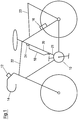
- the in Fig. 1 The vehicle shown is an electric bicycle, for example an e-bike or a pedelec, which is equipped with an electric drive motor 10.
- the drive motor is 10 arranged in the area of a bottom bracket of the vehicle. But it is also possible to attach the drive motor 10 to a front wheel hub or a rear wheel hub of the vehicle.
- a control unit is provided which is implemented in an on-board computer 12 which is attached in the area of a handlebar 14 of the vehicle and can be removed by a user of the vehicle when leaving the vehicle.
- the vehicle also has an electric frame lock 16, which is also controlled by the control unit.
- the control unit is configured in such a way that it automatically triggers a locking of the frame lock 16 when the on-board computer 12 is removed from the vehicle.
- a battery 18 is provided which is accommodated in a battery compartment 20 which is formed on a seat tube 21 of a frame 22 of the vehicle.
- a battery compartment 20 which is formed on a seat tube 21 of a frame 22 of the vehicle.
- the battery 18 has a power connection, not shown, which enables the battery 18 to be charged directly on the vehicle. In addition, the battery 18 can be removed from the battery compartment 20 for maintenance or replacement purposes or for charging away from the vehicle.
- a battery lock 24 which secures the battery 18 in the battery compartment 20.
- the battery lock 24 is integrated into the battery compartment 20 and designed so that it automatically assumes a locked state as soon as the Battery 18 is inserted into the battery compartment 20, for example by a spring-biased bolt, not shown, engaging in a latching recess of the battery 18 or a battery housing or by blocking a lever pivoted when the battery 18 is inserted. In this way, the battery 18 accommodated in the battery compartment 20 is normally secured by the locked battery lock 24.
- the battery lock 24 is unlocked electrically.
- the battery lock 24 comprises an electric drive, by means of which the bolt can be brought, at least temporarily, against the restoring force of the spring into an unlocking position that releases the battery 18.
- the electric drive can comprise an electric motor and an eccentric which is connected between the electric motor and the bolt.
- the electric drive can comprise an electromagnetic actuator, for example the bolt can be formed from a magnetic material and form an armature surrounded by a coil.
- the control unit implemented in the on-board computer 12 which also controls the drive motor 10 and the frame lock 16.
- the unlocking of the battery lock 24 is triggered by a user input on the on-board computer 12, for example by the user pressing a corresponding button on the on-board computer 12.
- a corresponding unlocking button is provided on the battery lock 24 itself and the control unit only outputs a release signal to the battery lock 24, which is a prerequisite for activating the unlocking button.
- the battery lock 24 can only be unlocked if the on-board computer 12 is attached to the vehicle, so that unauthorized unlocking and removal of the battery 18 with the on-board computer 12 removed is impossible or at least made more difficult.
- the control unit is configured in such a way that, when the on-board computer 12 is removed, it triggers a locking of the frame lock 16 before the battery lock 24 is unlocked. In this way it is prevented that the frame lock 16 can no longer lock because the battery 18 has been removed from the battery compartment 20.
- control unit is configured in such a way that it blocks locking of the frame lock 16 as long as the vehicle is in motion.
- the control unit receives data from at least one suitable sensor (not shown) provided on the vehicle, for example a motion sensor, position sensor, speed sensor and / or cadence sensor, and uses this data to determine the state of motion of the vehicle.
- the control unit also uses the same criterion for the battery lock 24 in order to prevent the battery lock 24 from being accidentally unlocked while driving.
Landscapes
- Engineering & Computer Science (AREA)
- Mechanical Engineering (AREA)
- Chemical & Material Sciences (AREA)
- Combustion & Propulsion (AREA)
- Transportation (AREA)
- Lock And Its Accessories (AREA)
- Arrangement Or Mounting Of Propulsion Units For Vehicles (AREA)
- Electric Propulsion And Braking For Vehicles (AREA)
- Battery Mounting, Suspending (AREA)
Abstract
Description
- Die vorliegende Erfindung betrifft ein Fahrzeug mit einem elektrisch betriebenen Antriebsmotor, einer Batterie zur Energieversorgung des Antriebsmotors, welche durch ein Batterieschloss in einem Batteriefach des Fahrzeugs gesichert ist und nach Entriegelung des Batterieschlosses aus dem Batteriefach entnehmbar ist, und einer Steuereinheit für das Batterieschloss.
- Derartige Fahrzeuge sind grundsätzlich bekannt, zum Beispiel in Form von E-Bikes oder Pedelecs. Zur Sicherung der Batterie weisen diese bekannten Fahrzeuge üblicherweise ein mechanisches Batterieschloss auf, welches mittels eines Schlüssels entriegelt werden kann.
- Der Erfindung liegt die Aufgabe zugrunde, ein Fahrzeug zu schaffen, das sich durch einen höheren Bedienkomfort und eine höhere Wirtschaftlichkeit auszeichnet.
- Zur Lösung der Aufgabe ist ein Fahrzeug mit den Merkmalen des Anspruchs 1 vorgesehen.
- Der Erfindung liegt der allgemeine Gedanke zugrunde, das herkömmliche mechanische Batterieschloss durch ein elektrisch entriegelbares Batterieschloss zu ersetzen, wodurch auf einen physikalischen Schlüssel zur Entriegelung des Batterieschlosses verzichtet werden kann, welchen der Benutzer des Fahrzeugs stets bei sich tragen müsste und welchen er bei Bedarf unter Umständen nicht zur Hand hätte. Bei dem Fahrzeug kann es sich beispielsweise um ein Elektrofahrrad, insbesondere E-Bike oder Pedelec, ein Elektrodreirad, einen Elektrorollstuhl, ein Elektroquad oder dergleichen handeln.
- Vorteilhafte Ausbildungen der Erfindung sind den Unteransprüchen, der Beschreibung und der Zeichnung zu entnehmen.
- Gemäß einer besonders bevorzugten Ausführungsform wird das Batterieschloss nach dem Einsetzen der Batterie in das Batteriefach automatisch verriegelt. Solange die Batterie am Fahrzeug montiert ist, ist der Normalzustand des Batterieschlosses also ein verriegelter. Hierdurch ist die Batterie stets zuverlässig am Fahrzeug gesichert, und der Benutzer braucht nicht an eine aktive Verriegelung des Batterieschlosses zu denken. Grundsätzlich ist aber auch eine Ausführungsform denkbar, bei welcher das Batterieschloss regelmäßig entriegelt ist und erst bei Verlassen des Fahrzeugs verriegelt wird, z.B. wenn ein Bordcomputer von dem Fahrzeug abgenommen wird.
- Gemäß einer weiteren Ausführungsform ist die Steuereinheit in eine Motorsteuerung für den Antriebsmotor integriert. Die Entriegelung des Batterieschlosses wird letztlich also durch die Motorsteuerung gesteuert. Die für die Steuerung des Antriebsmotors ohnehin vorhandene Motorsteuerung übernimmt mit anderen Worten eine Zusatzfunktion, und es braucht keine zusätzliche eigene Steuereinheit zur Entriegelung des Batterieschlosses vorgesehen werden.
- Vorteilhafterweise ist die Steuereinheit in einem Bordcomputer implementiert, welcher durch einen Benutzer abnehmbar an dem Fahrzeug angebracht ist. Da der Benutzer den Bordcomputer bei einem Verlassen des Fahrzeugs üblicherweise mit sich nimmt, ist gewährleistet, dass Unbefugte das Batterieschloss zumindest nicht ohne kriminell tätig zu werden entriegeln und die Batterie entwenden können. Gemäß einer Ausführungsform umfasst der Bordcomputer ein durch einen Benutzer betätigbares Eingabemittel zur Entriegelung des Batterieschlosses. Bei diesem Eingabemittel kann es sich beispielsweise um einen Druck- oder Schiebeschalter handeln. Alternativ kann der Bordcomputer über einen Touchscreen oder ein Mikrophon verfügen, über den bzw. das ein entsprechender Entriegelungsbefehl eingegeben werden kann.
- Anstatt in die Motorsteuerung integriert zu sein, kann die Steuereinheit auch in das Batterieschloss integriert sein. In diesem Fall ist das Batterieschloss also mit einer eigenen, insbesondere von der Motorsteuerung unabhängigen, Steuereinheit versehen und dementsprechend autark. Gleichwohl ist es vorteilhaft, wenn die in das Batterieschloss integrierte Steuereinheit mit einem Bordcomputer des Fahrzeugs verbunden ist, da die Steuereinheit auf diese Weise mit dem Bordcomputer kommunizieren kann, beispielsweise um ein die Entriegelung des Batterieschlosses erlaubendes Freigabesignal oder ein den Bewegungszustand des Fahrzeugs angebendes Signal von diesem zu erhalten oder ein den Verriegelungszustand des Batterieschlosses angebendes Signal an den Bordcomputer zu übermitteln.
- Insbesondere wenn die Steuereinheit in das Batterieschloss integriert ist, verfügt das Batterieschloss bevorzugt über ein durch einen Benutzer, insbesondere manuell, betätigbares Bedienelement zur Entriegelung des Batterieschlosses. In diesem Fall erfolgt die Entriegelung des Batterieschlosses also nicht über eine Eingabe an dem Bordcomputer, sondern stattdessen durch Betätigung des Bedienelements am Batterieschloss. Bei dem Bedienelement kann es sich beispielsweise um einen Druck- oder Schiebeschalter handeln oder auch um einen kapazitiven Sensor, der z.B. die Anwesenheit eines Fingers des Benutzers detektieren kann. Grundsätzlich kann das Batterieschloss ein solches manuell betätigbares Bedienelement aber auch dann aufweisen, wenn die Steuereinheit in dem Bordcomputer implementiert ist.
- In beiden Fällen wird ein höherer Diebstahlschutz erreicht, wenn die Steuereinheit eine Entriegelung des Batterieschlosses mittels des Bedienelements nur solange zulässt, wie der Bordcomputer an dem Fahrzeug angebracht ist. Die Entriegelung des Batterieschlosses mittels des Bedienelements setzt somit auch hier voraus, dass sich der Bordcomputer am Fahrzeug befindet. Anders gesagt ist eine, insbesondere unbefugte, Entriegelung des Batterieschlosses durch das Bedienelement dann ausgeschlossen, wenn der rechtmäßige Benutzer das Fahrzeug verlassen und den Bordcomputer mit sich genommen hat.
- Gemäß einer weiteren Ausführungsform weist das Fahrzeug ein elektrisch verriegelbares Rahmenschloss auf, welches durch Abnahme eines Bordcomputers von dem Fahrzeug elektrisch verriegelbar ist.
- Dabei ist es vorteilhaft, wenn die Steuereinheit eine Entriegelung des Batterieschlosses nur dann zulässt, wenn das Rahmenschloss verriegelt ist. Da die elektrische Verriegelung des Rahmenschlosses eine Versorgung mit elektrischer Energie durch die Batterie voraussetzt, ist durch diese Steuerabfolge sichergestellt, dass die Batterie nicht vorzeitig aus dem Batteriefach entnommen und die Versorgung des Rahmenschlosses mit elektrischer Energie unterbrochen werden kann, bevor das Rahmenschloss verriegelt ist.
- Alternativ oder zusätzlich kann die Steuereinheit eine Entriegelung des Batterieschlosses blockieren, solange das Fahrzeug in Bewegung ist. Auf diese Weise wird eine unbeabsichtigte Entriegelung des Batterieschlosses während der Fahrt verhindert, die unter Umständen zu einem Herausfallen der Batterie aus dem Batteriefach führen könnte.
- Beispielsweise kann der Bordcomputer Daten von einem Bewegungssensor, Lagesensor, Geschwindigkeitssensor und/oder Trittfrequenzsensor des Fahrzeugs empfangen, aus diesen Daten ermitteln, ob das Fahrzeug in Bewegung ist, und ein den Bewegungszustand des Fahrzeugs angebendes Signal an die Steuereinheit übermitteln.
- Vorzugsweise umfasst das Batterieschloss einen Riegel, welcher in einer Verriegelungsstellung die in dem Batteriefach aufgenommene Batterie verriegelt und welcher durch einen elektrischen Antrieb in eine Entriegelungsstellung bringbar ist, in welcher der Riegel die in dem Batteriefach aufgenommene Batterie freigibt. Um beim Einsetzen der Batterie in das Batteriefach die Batterie automatisch und insbesondere stromlos verriegeln zu können, ist der Riegel bevorzugt durch eine Feder in seine Verriegelungsstellung vorgespannt. Denkbar ist aber auch eine Ausführungsform, bei welcher entsprechend der Entriegelung auch die Verriegelung elektrisch erfolgt.
- Ist das Batterieschloss rahmenseitig angeordnet, beispielsweise in das Batteriefach integriert oder davon getrennt an einem Rahmen des Fahrzeugs angebracht, so kann der Riegel gemäß einer Variante in seiner Verriegelungsstellung in eine Riegelaufnahme der in dem Batteriefach aufgenommenen Batterie eingreifen. Die Riegelaufnahme der Batterie kann zum Beispiel in einem die Batterie umgebenden Batteriegehäuse ausgebildet sein.
- Umgekehrt ist es auch möglich, das Batterieschloss batterieseitig anzuordnen und insbesondere in ein die Batterie umgebendes Batteriegehäuse zu integrieren. In diesem Fall würde der Riegel bei in das Batteriefach eingesetzter Batterie in seiner Verriegelungsstellung in eine rahmenseitig vorgesehene Riegelaufnahme eingreifen, welche beispielsweise in das Batteriefach integriert ist oder davon getrennt an dem Rahmen des Fahrzeugs ausgebildet ist.
- Gemäß einer alternativen Variante blockiert der Riegel einen Hebel, durch welchen die Batterie aus dem Batteriefach heraus hebelbar ist. Im Falle eines rahmenseitig angeordneten Batterieschlosses wirkt der Riegel in seiner Verriegelungsstellung also indirekt mit der in dem Batteriefach aufgenommenen Batterie zusammen. Auch bei dieser Variante ist es grundsätzlich vorstellbar, das Batterieschloss batterieseitig anzuordnen und insbesondere in ein die Batterie umgebendes Batteriegehäuse zu integrieren und, wenn die Batterie in das Batteriefach eingesetzt ist, mittels eines Riegels des Batterieschlosses einen Hebel zu blockieren, durch welchen die Batterie aus dem Batteriefach heraus hebelbar ist.
- Der elektrische Antrieb für den Riegel kann beispielsweise einen Elektromotor und einen Exzenter umfassen, welcher zwischen den Elektromotor und den Riegel geschaltet ist.
- Alternativ kann der elektrische Antrieb einen elektromagnetischen Aktuator umfassen, zum Beispiel kann der Riegel aus einem magnetischen Material gebildet sein und einen von einer Spule umgebenen Anker bilden.
- Abschließend sei darauf hingewiesen, dass alternativ oder zusätzlich zu dem Batterieschloss auch ein anderes elektrisch entriegelbares Schloss des Fahrzeugs, durch welches zum Beispiel ein Aufbewahrungsfach, Behälter oder Koffer des Fahrzeugs verriegelbar ist oder durch welches ein anderes Zubehörteil am Fahrzeug sicherbar ist, auf die voranstehend beschriebene Art und Weise ausgebildet und gesteuert sein kann, insbesondere elektrisch entriegelt werden kann.
- Nachfolgend wird die Erfindung unter Bezugnahme auf die beigefügte Zeichnung rein beispielhaft anhand einer möglichen Ausführungsform beschrieben.
- Fig. 1
- zeigt ein erfindungsgemäßes Fahrzeug.
- Bei dem in
Fig. 1 gezeigten Fahrzeug handelt es sich um ein Elektrofahrrad, beispielsweise ein E-Bike oder ein Pedelec, welches mit einem elektrischen Antriebsmotor 10 ausgestattet ist. Im vorliegenden Ausführungsbeispiel ist der Antriebsmotor 10 im Bereich eines Tretlagers des Fahrzeugs angeordnet. Es ist aber ebenso möglich, den Antriebsmotor 10 an einer Vorderradnabe oder einer Hinterradnabe des Fahrzeugs anzubringen. - Zur Steuerung des Antriebsmotors 10 ist eine Steuereinheit vorgesehen, die in einem Bordcomputer 12 implementiert ist, welcher im Bereich eines Lenkers 14 des Fahrzeugs angebracht ist und von einem Benutzer des Fahrzeugs beim Verlassen des Fahrzeugs abgenommen werden kann.
- Das Fahrzeug verfügt ferner über ein elektrisches Rahmenschloss 16, welches ebenfalls durch die Steuereinheit gesteuert wird. Konkret ist die Steuereinheit so konfiguriert, dass sie automatisch eine Verriegelung des Rahmenschlosses 16 auslöst, wenn der Bordcomputer 12 vom Fahrzeug abgenommen wird.
- Zur Versorgung sowohl des Antriebsmotors 10 als auch des Rahmenschlosses 16 mit elektrischer Energie ist eine Batterie 18 vorgesehen, welche in einem Batteriefach 20 aufgenommen ist, das an einem Sitzrohr 21 eines Rahmens 22 des Fahrzeugs ausgebildet ist. Alternativ ist es möglich, die Batterie 18 und das Batteriefach 20 in einen Gepäckträger 23 des Fahrzeugs zu integrieren.
- Die Batterie 18 verfügt über einen nicht gezeigten Stromanschluss, welcher ein Aufladen der Batterie 18 direkt am Fahrzeug ermöglicht. Darüber hinaus kann die Batterie 18 zu Wartungs- oder Austauschzwecken oder für ein vom Fahrzeug entferntes Aufladen aus dem Batteriefach 20 entnommen werden.
- Um eine unbefugte Entnahme und ein unbeabsichtigtes Herausfallen der Batterie 18 aus dem Batteriefach 20 zu verhindern, ist ein Batterieschloss 24 vorgesehen, welches die Batterie 18 in dem Batteriefach 20 sichert. Im vorliegenden Ausführungsbeispiel ist das Batterieschloss 24 in das Batteriefach 20 integriert und so ausgebildet, dass es automatisch einen verriegelten Zustand einnimmt, sobald die Batterie 18 in das Batteriefach 20 eingesetzt wird, beispielsweise indem ein nicht dargestellter und durch eine Feder vorgespannter Riegel in eine Rastvertiefung der Batterie 18 oder eines Batteriegehäuses einrastet oder einen beim Einsetzen der Batterie 18 verschwenkten Hebel blockiert. Auf diese Weise ist die in dem Batteriefach 20 aufgenommene Batterie 18 normal durch das verriegelte Batterieschloss 24 gesichert.
- Die Entriegelung des Batterieschlosses 24 erfolgt elektrisch. Hierzu umfasst das Batterieschloss 24 einen elektrischen Antrieb, durch welchen der Riegel zumindest vorübergehend entgegen der Rückstellkraft der Feder in eine die Batterie 18 freigebende Entriegelungsstellung bringbar ist. Beispielsweise kann der elektrische Antrieb einen Elektromotor und einen Exzenter umfassen, welcher zwischen den Elektromotor und den Riegel geschaltet ist. Alternativ kann der elektrische Antrieb einen elektromagnetischen Aktuator umfassen, zum Beispiel kann der Riegel aus einem magnetischen Material gebildet sein und einen von einer Spule umgebenen Anker bilden.
- Zur Steuerung des Batterieschlosses 24 ist die in dem Bordcomputer 12 implementierte Steuereinheit vorgesehen, welche auch den Antriebsmotor 10 und das Rahmenschloss 16 steuert. Im vorliegenden Ausführungsbeispiel wird die Entriegelung des Batterieschlosses 24 durch eine Benutzereingabe am Bordcomputer 12 ausgelöst, beispielsweise indem der Benutzer eine entsprechende Taste am Bordcomputer 12 drückt. Alternativ ist aber auch eine Ausführungsform denkbar, bei welcher am Batterieschloss 24 selbst eine entsprechende Entriegelungstaste vorgesehen ist und die Steuereinheit lediglich ein Freigabesignal an das Batterieschloss 24 ausgibt, welches Voraussetzung für eine Aktivierung der Entriegelungstaste ist. In beiden Fällen lässt sich das Batterieschloss 24 nur dann entriegeln, wenn der Bordcomputer 12 am Fahrzeug angebracht ist, so dass eine unbefugte Entriegelung und Entnahme der Batterie 18 bei abgenommenem Bordcomputer 12 unmöglich oder zumindest erschwert ist.
- Da das Rahmenschloss 16 für seine Verriegelung auf die Versorgung mit Energie durch die Batterie 18 angewiesen ist, ist die Steuereinheit so konfiguriert, dass sie bei einer Abnahme des Bordcomputers 12 eine Verriegelung des Rahmenschlosses 16 auslöst, bevor das Batterieschloss 24 entriegelt wird. Auf diese Weise wird verhindert, dass das Rahmenschloss 16 nicht mehr verriegeln kann, weil die Batterie 18 aus dem Batteriefach 20 entnommen ist.
- Ferner ist die Steuereinheit derart konfiguriert, dass sie eine Verriegelung des Rahmenschlosses 16 solange blockiert, wie das Fahrzeug in Bewegung ist. Die Steuereinheit empfängt hierfür Daten von wenigstens einem geeigneten am Fahrzeug vorgesehenen Sensor (nicht gezeigt), z.B. einem Bewegungssensor, Lagesensor, Geschwindigkeitssensor und/oder Trittfrequenzsensor, und ermittelt aus diesen Daten den Bewegungszustand des Fahrzeugs. Dasselbe Kriterium verwendet die Steuereinheit auch für das Batterieschloss 24, um zu verhindern, dass das Batterieschloss 24 versehentlich während der Fahrt entriegelt wird.
-
- 10
- Antriebsmotor
- 12
- Bordcomputer
- 14
- Lenker
- 16
- Rahmenschloss
- 18
- Batterie
- 20
- Batteriefach
- 21
- Sitzrohr
- 22
- Rahmen
- 23
- Gepäckträger
- 24
- Batterieschloss
Claims (14)
- Elektrofahrrad mit einem elektrisch betriebenen Antriebsmotor (10), einer Batterie (18) zur Energieversorgung des Antriebsmotors (10), welche durch ein elektrisch entriegelbares Batterieschloss (24) in einem Batteriefach (20) des Elektrofahrrads gesichert ist und nach Entriegelung des Batterieschlosses (24) aus dem Batteriefach (20) entnehmbar ist, und einer Steuereinheit für das Batterieschloss (24),
wobei die Steuereinheit eine Entriegelung des Batterieschlosses (24) blockiert, solange das Elektrofahrrad in Bewegung ist. - Elektrofahrrad nach Anspruch 1,
dadurch gekennzeichnet, dass
das Batterieschloss (24) nach dem Einsetzen der Batterie (18) in das Batteriefach (20) automatisch verriegelt. - Elektrofahrrad nach Anspruch 1 oder 2,
dadurch gekennzeichnet, dass
die Steuereinheit in eine Motorsteuerung für den Antriebsmotor (10) integriert ist. - Elektrofahrrad nach zumindest einem der vorstehenden Ansprüche,
dadurch gekennzeichnet, dass
die Steuereinheit in einem Bordcomputer (12) implementiert ist, welcher durch einen Benutzer abnehmbar an dem Elektrofahrrad angebracht ist. - Elektrofahrrad nach Anspruch 4,
dadurch gekennzeichnet, dass
der Bordcomputer (12) ein durch einen Benutzer betätigbares Eingabemittel zur Entriegelung des Batterieschlosses (24) aufweist. - Elektrofahrrad nach Anspruch 1 oder 2,
dadurch gekennzeichnet, dass
die Steuereinheit in das Batterieschloss (24) integriert ist. - Elektrofahrrad nach zumindest einem der vorstehenden Ansprüche,
dadurch gekennzeichnet, dass
das Batterieschloss (24) über ein durch einen Benutzer, insbesondere manuell, betätigbares Bedienelement zur Entriegelung des Batterieschlosses (24) verfügt. - Elektrofahrrad nach Anspruch 7,
dadurch gekennzeichnet, dass
die Steuereinheit eine Entriegelung des Batterieschlosses (24) mittels des Bedienelements nur solange zulässt, wie ein Bordcomputer (12) an dem Elektrofahrrad angebracht ist. - Elektrofahrrad nach zumindest einem der vorstehenden Ansprüche,
dadurch gekennzeichnet, dass
das Elektrofahrrad ein elektrisch verriegelbares Rahmenschloss (16) aufweist, welches durch Abnahme eines Bordcomputers (12) von dem Elektrofahrrad elektrisch verriegelbar ist,
insbesondere wobei die Steuereinheit eine Entriegelung des Batterieschlosses (24) nur dann zulässt, wenn das Rahmenschloss (16) verriegelt ist. - Elektrofahrrad nach zumindest einem der vorstehenden Ansprüche,
dadurch gekennzeichnet, dass
ein Bordcomputer (12) des Elektrofahrrads Daten von einem Bewegungssensor, Lagesensor, Geschwindigkeitssensor und/oder Trittfrequenzsensor des Elektrofahrrads empfängt, aus diesen Daten ermittelt, ob das Elektrofahrrad in Bewegung ist, und ein den Bewegungszustand des Elektrofahrrads angebendes Signal an die Steuereinheit übermittelt. - Elektrofahrrad nach zumindest einem der vorstehenden Ansprüche,
dadurch gekennzeichnet, dass
das Batterieschloss (24) einen Riegel umfasst, welcher in einer Verriegelungsstellung die in dem Batteriefach (20) aufgenommene Batterie (18) verriegelt und welcher durch einen elektrischen Antrieb in eine Entriegelungsstellung bringbar ist, in welcher der Riegel die in dem Batteriefach (20) aufgenommene Batterie (18) freigibt, insbesondere wobei der Riegel durch eine Feder in seine Verriegelungsstellung vorgespannt ist. - Elektrofahrrad nach Anspruch 11,
dadurch gekennzeichnet, dass
das Batterieschloss (24) rahmenseitig angeordnet ist und der Riegel in seiner Verriegelungsstellung in eine Riegelaufnahme der in dem Batteriefach (20) aufgenommenen Batterie (18) eingreift; oder
das Batterieschloss (24) batterieseitig angeordnet ist und der Riegel bei in dem Batteriefach (20) aufgenommener Batterie (18) in seiner Verriegelungsstellung in eine rahmenseitig ausgebildete Riegelaufnahme eingreift. - Elektrofahrrad nach Anspruch 11,
dadurch gekennzeichnet, dass der Riegel in seiner Verriegelungsstellung einen Hebel blockiert, durch welchen die Batterie (18) aus dem Batteriefach (20) heraus hebelbar ist. - Elektrofahrrad nach zumindest einem der Ansprüche 11 bis 13,
dadurch gekennzeichnet, dass
der elektrische Antrieb einen Elektromotor und einen Exzenter umfasst, welcher zwischen den Elektromotor und den Riegel geschaltet ist; oder der elektrische Antrieb einen elektromagnetischen Aktuator umfasst.
Applications Claiming Priority (3)
| Application Number | Priority Date | Filing Date | Title |
|---|---|---|---|
| DE102016119570.7A DE102016119570A1 (de) | 2016-10-13 | 2016-10-13 | Fahrzeug mit einem elektrisch betriebenen Antriebsmotor |
| EP17780340.0A EP3504114B1 (de) | 2016-10-13 | 2017-09-26 | Batterieschloss für ein elektrofahrzeug |
| PCT/EP2017/074312 WO2018069035A1 (de) | 2016-10-13 | 2017-09-26 | Batterieschloss für ein elektrofahrzeug |
Related Parent Applications (2)
| Application Number | Title | Priority Date | Filing Date |
|---|---|---|---|
| EP17780340.0A Division EP3504114B1 (de) | 2016-10-13 | 2017-09-26 | Batterieschloss für ein elektrofahrzeug |
| EP17780340.0A Division-Into EP3504114B1 (de) | 2016-10-13 | 2017-09-26 | Batterieschloss für ein elektrofahrzeug |
Publications (2)
| Publication Number | Publication Date |
|---|---|
| EP3770053A1 true EP3770053A1 (de) | 2021-01-27 |
| EP3770053B1 EP3770053B1 (de) | 2022-01-12 |
Family
ID=60022063
Family Applications (2)
| Application Number | Title | Priority Date | Filing Date |
|---|---|---|---|
| EP17780340.0A Active EP3504114B1 (de) | 2016-10-13 | 2017-09-26 | Batterieschloss für ein elektrofahrzeug |
| EP20196169.5A Active EP3770053B1 (de) | 2016-10-13 | 2017-09-26 | Batterieschloss für ein elektrofahrrad |
Family Applications Before (1)
| Application Number | Title | Priority Date | Filing Date |
|---|---|---|---|
| EP17780340.0A Active EP3504114B1 (de) | 2016-10-13 | 2017-09-26 | Batterieschloss für ein elektrofahrzeug |
Country Status (11)
| Country | Link |
|---|---|
| US (1) | US11235838B2 (de) |
| EP (2) | EP3504114B1 (de) |
| CN (1) | CN109923034B (de) |
| BR (1) | BR112019007491A2 (de) |
| CA (1) | CA3040010A1 (de) |
| DE (1) | DE102016119570A1 (de) |
| DK (1) | DK3770053T3 (de) |
| ES (2) | ES2961891T3 (de) |
| PT (1) | PT3770053T (de) |
| TW (1) | TWI741043B (de) |
| WO (1) | WO2018069035A1 (de) |
Cited By (1)
| Publication number | Priority date | Publication date | Assignee | Title |
|---|---|---|---|---|
| KR20220149991A (ko) * | 2021-05-03 | 2022-11-10 | 삼천리자전거 주식회사 | 멀티배터리용 콘트롤러 및 이를 구비한 자전거 |
Families Citing this family (10)
| Publication number | Priority date | Publication date | Assignee | Title |
|---|---|---|---|---|
| DE102018111296A1 (de) * | 2018-05-11 | 2019-11-14 | ABUS August Bremicker Söhne KG | Mobiles Schloss |
| JP6999491B2 (ja) * | 2018-05-18 | 2022-01-18 | 株式会社シマノ | ロックシステム |
| TWI659880B (zh) * | 2018-08-17 | 2019-05-21 | 陳旺松 | 可手動操控及無線遙控的鎖裝置及應用其的自行車 |
| CN112018280A (zh) * | 2019-05-29 | 2020-12-01 | 政亮企业股份有限公司 | 电池固定机构 |
| WO2021114301A1 (zh) * | 2019-12-13 | 2021-06-17 | 苏州锂智车业科技有限公司 | 一种用于电动自行车的充电系统 |
| US11565769B2 (en) | 2020-12-11 | 2023-01-31 | Specialized Bicycle Components, Inc. | 3-position battery latching system |
| DE102021202381A1 (de) | 2021-03-11 | 2022-09-15 | Volkswagen Aktiengesellschaft | Vorrichtung, Verfahren und System zum Sichern eines wiederaufladbaren Speichermoduls für elektrische Energie |
| EP4067216A1 (de) * | 2021-03-29 | 2022-10-05 | TVS Motor Company Limited | Antriebseinheitsverriegelungsvorrichtung für ein sattelfahrzeug |
| DE102021122247A1 (de) | 2021-08-27 | 2023-03-02 | ABUS August Bremicker Söhne Kommanditgesellschaft | Elektromechanisches Schloss |
| DE102022117829A1 (de) | 2022-07-18 | 2024-01-18 | Bayerische Motoren Werke Aktiengesellschaft | Anordnung eines Verkleidungsteils an einem Bauelement eines Kraftrads sowie Verfahren |
Citations (5)
| Publication number | Priority date | Publication date | Assignee | Title |
|---|---|---|---|---|
| JPH08175466A (ja) * | 1994-12-27 | 1996-07-09 | Sanyo Electric Co Ltd | 電動自転車 |
| EP2423096A2 (de) * | 2010-08-26 | 2012-02-29 | Cycling Sports Group, Inc. | Fahrrad |
| CN202202658U (zh) * | 2011-07-25 | 2012-04-25 | 张毓敏 | 电动自行车遥控电池盒锁的驱动装置 |
| DE102011083031A1 (de) * | 2011-09-20 | 2012-08-09 | Robert Bosch Gmbh | Verriegelungsvorrichtung |
| CN105386661A (zh) * | 2015-06-24 | 2016-03-09 | 徐小强 | 一种智能遥控自行车锁 |
Family Cites Families (33)
| Publication number | Priority date | Publication date | Assignee | Title |
|---|---|---|---|---|
| JP2623050B2 (ja) * | 1992-05-26 | 1997-06-25 | ヤマハ発動機株式会社 | 電動自転車用バッテリーケースの取付構造 |
| TW348705U (en) * | 1994-12-07 | 1998-12-21 | Honda Motor Co Ltd | Battery case mounting structure for motor-driven vehicle |
| JPH09216588A (ja) * | 1996-02-13 | 1997-08-19 | Suzuki Motor Corp | 電動自転車のバッテリ取付構造 |
| JP3622021B2 (ja) * | 1996-07-31 | 2005-02-23 | ヤマハ発動機株式会社 | 脱着式バッテリボックスのロック機構 |
| JP3622020B2 (ja) * | 1996-07-31 | 2005-02-23 | ヤマハ発動機株式会社 | 電動自転車のバッテリボックス脱着構造 |
| JPH10181651A (ja) | 1996-12-26 | 1998-07-07 | Yamaha Motor Co Ltd | 電動自転車のバッテリボックス固定構造 |
| JP4132127B2 (ja) * | 1997-05-09 | 2008-08-13 | 本田技研工業株式会社 | バッテリ供給装置 |
| JP4301421B2 (ja) * | 1999-10-13 | 2009-07-22 | 本田技研工業株式会社 | 補助動力付き自転車のバッテリ施錠装置 |
| JP2007015641A (ja) * | 2005-07-11 | 2007-01-25 | Yamaha Motor Co Ltd | 電動自転車 |
| ATE555976T1 (de) * | 2009-03-20 | 2012-05-15 | Thoemus Veloshop Ag | Fahrradrahmen zur aufnahme einer batterieeinheit und zugehörige batterieeinheit |
| CH701675B1 (de) * | 2009-08-20 | 2014-09-15 | Fairly Bike Mfg Co Ltd | Batteriehalterung. |
| JP4915447B2 (ja) * | 2009-12-25 | 2012-04-11 | トヨタ自動車株式会社 | バッテリの車両搭載構造 |
| FR2958259B1 (fr) * | 2010-04-01 | 2014-04-11 | Matra Mfg & Services | Deux-roues electrique |
| US8413947B2 (en) * | 2010-11-12 | 2013-04-09 | Joy Industrial Co., Ltd. | Positioning device for battery box |
| DE102011018185A1 (de) * | 2011-04-19 | 2012-10-25 | ABUS August Bremicker Söhne KG | Verriegelungssystem |
| WO2012160407A1 (en) | 2011-05-20 | 2012-11-29 | Better Place GmbH | Multi-motor latch assembly |
| US8560147B2 (en) * | 2011-07-26 | 2013-10-15 | Gogoro, Inc. | Apparatus, method and article for physical security of power storage devices in vehicles |
| WO2013134164A1 (en) * | 2012-03-03 | 2013-09-12 | Nathan Jauvtis | Power assisted vehicle |
| US8727367B2 (en) * | 2012-03-16 | 2014-05-20 | Specialized Bicycle Components, Inc. | Bicycle with integrated cable routing |
| US8979110B2 (en) * | 2012-03-16 | 2015-03-17 | Specialized Bicycle Components, Inc. | Bicycle with battery mount |
| CN104512494A (zh) * | 2013-09-29 | 2015-04-15 | 凹凸电子(武汉)有限公司 | 电动车辆及其管理方法 |
| US9124085B2 (en) * | 2013-11-04 | 2015-09-01 | Gogoro Inc. | Apparatus, method and article for power storage device failure safety |
| US9260080B2 (en) * | 2014-04-14 | 2016-02-16 | Ford Global Technologies, Inc. | Electric vehicle service disconnect lock |
| CN104097723B (zh) * | 2014-06-23 | 2017-10-03 | 苏州达方电子有限公司 | 适用于电动脚踏车的车架 |
| CN204451980U (zh) * | 2015-03-11 | 2015-07-08 | 谷金鹏 | 一种电动汽车动力电池的系统及电动汽车 |
| JP6422808B2 (ja) * | 2015-03-31 | 2018-11-14 | 株式会社シマノ | 自転車用バッテリホルダおよび自転車用バッテリシステム |
| CN204701700U (zh) * | 2015-05-28 | 2015-10-14 | 无锡科技职业学院 | 车锁系统 |
| US9616966B2 (en) * | 2015-06-26 | 2017-04-11 | Specialized Bicycle Components, Inc. | Bicycle frame with reinforced motor mount |
| US9580141B2 (en) * | 2015-06-26 | 2017-02-28 | Specialized Bicycle Components, Inc. | Bicycle frame with improved battery mount |
| TWM514946U (zh) * | 2015-10-01 | 2016-01-01 | 菲力工業股份有限公司 | 電動腳踏車車架 |
| US10183591B2 (en) * | 2015-12-18 | 2019-01-22 | Darfon Electronics (Suzhou) Co., Ltd. | Electric bicycle and battery lift mechanism and battery carrying device thereof |
| CN205303556U (zh) * | 2016-01-04 | 2016-06-08 | 爱玛科技集团股份有限公司 | 一种电动车锂电池盒安装结构 |
| ES2784650T3 (es) * | 2016-08-10 | 2020-09-29 | Bh Bikes Europe S L | Cuadro de bicicleta eléctrica y bicicleta eléctrica |
-
2016
- 2016-10-13 DE DE102016119570.7A patent/DE102016119570A1/de active Pending
-
2017
- 2017-09-26 ES ES17780340T patent/ES2961891T3/es active Active
- 2017-09-26 WO PCT/EP2017/074312 patent/WO2018069035A1/de unknown
- 2017-09-26 PT PT201961695T patent/PT3770053T/pt unknown
- 2017-09-26 US US16/341,680 patent/US11235838B2/en active Active
- 2017-09-26 EP EP17780340.0A patent/EP3504114B1/de active Active
- 2017-09-26 EP EP20196169.5A patent/EP3770053B1/de active Active
- 2017-09-26 ES ES20196169T patent/ES2906233T3/es active Active
- 2017-09-26 DK DK20196169.5T patent/DK3770053T3/da active
- 2017-09-26 BR BR112019007491A patent/BR112019007491A2/pt not_active Application Discontinuation
- 2017-09-26 CA CA3040010A patent/CA3040010A1/en active Pending
- 2017-09-26 CN CN201780062615.9A patent/CN109923034B/zh active Active
- 2017-10-11 TW TW106134735A patent/TWI741043B/zh active
Patent Citations (5)
| Publication number | Priority date | Publication date | Assignee | Title |
|---|---|---|---|---|
| JPH08175466A (ja) * | 1994-12-27 | 1996-07-09 | Sanyo Electric Co Ltd | 電動自転車 |
| EP2423096A2 (de) * | 2010-08-26 | 2012-02-29 | Cycling Sports Group, Inc. | Fahrrad |
| CN202202658U (zh) * | 2011-07-25 | 2012-04-25 | 张毓敏 | 电动自行车遥控电池盒锁的驱动装置 |
| DE102011083031A1 (de) * | 2011-09-20 | 2012-08-09 | Robert Bosch Gmbh | Verriegelungsvorrichtung |
| CN105386661A (zh) * | 2015-06-24 | 2016-03-09 | 徐小强 | 一种智能遥控自行车锁 |
Cited By (1)
| Publication number | Priority date | Publication date | Assignee | Title |
|---|---|---|---|---|
| KR20220149991A (ko) * | 2021-05-03 | 2022-11-10 | 삼천리자전거 주식회사 | 멀티배터리용 콘트롤러 및 이를 구비한 자전거 |
Also Published As
| Publication number | Publication date |
|---|---|
| PT3770053T (pt) | 2022-02-11 |
| DE102016119570A1 (de) | 2018-04-19 |
| EP3504114A1 (de) | 2019-07-03 |
| ES2961891T3 (es) | 2024-03-14 |
| EP3770053B1 (de) | 2022-01-12 |
| EP3504114B1 (de) | 2023-08-30 |
| CA3040010A1 (en) | 2018-04-19 |
| ES2906233T3 (es) | 2022-04-13 |
| CN109923034B (zh) | 2021-01-12 |
| TW201815621A (zh) | 2018-05-01 |
| US20200039607A1 (en) | 2020-02-06 |
| CN109923034A (zh) | 2019-06-21 |
| EP3504114C0 (de) | 2023-08-30 |
| US11235838B2 (en) | 2022-02-01 |
| TWI741043B (zh) | 2021-10-01 |
| DK3770053T3 (en) | 2022-04-19 |
| BR112019007491A2 (pt) | 2022-01-04 |
| WO2018069035A1 (de) | 2018-04-19 |
Similar Documents
| Publication | Publication Date | Title |
|---|---|---|
| EP3770053B1 (de) | Batterieschloss für ein elektrofahrrad | |
| EP3362338B1 (de) | Elektrofahrrad, wegfahrsperre für ein elektrofahrrad und verfahren zum betrieb eines elektrofahrrades | |
| DE102018006690A1 (de) | Fahrzeug | |
| DE102012004176A1 (de) | Integrierte Diebstahlsicherung für ein Elektrofahrrad | |
| WO2011003407A1 (de) | Sicherungsvorrichtung und verfahren zur verhinderung einer unbefugten inbetriebnahme eines fahrzeuges | |
| DE102008020950A1 (de) | Schloss für Fahrzeuge | |
| DE102013210358A1 (de) | Verfahren und Vorrichtung zur Realisierung eines elektrischen Fahrradschlosses | |
| EP3159254A1 (de) | Fahrzeug, insbesondere elektrofahrrad | |
| DE102018111301A1 (de) | Mobiles Schloss | |
| DE102011004464A1 (de) | Sicherungssystem für ein Zweirad | |
| DE102018005331A1 (de) | Fahrzeug | |
| DE102007062252A1 (de) | Kraftfahrzeug mit Trägersystem und Diebstahlwarnanlage | |
| DE202016002087U1 (de) | Elektronisches Fahrradschloss | |
| DE202019005536U1 (de) | Fahrzeug | |
| DE102011006444A1 (de) | Diebstahlschutz für Zweiradfahrzeuge | |
| DE102008056546B4 (de) | Entleihsystem für Fahrräder | |
| EP3116771B1 (de) | Gepäcksystem für ein motorisiertes zweirad | |
| DE102010061143A1 (de) | Sicherheitssystem sowie Verfahren zum Betreiben eines Sicherheitssystems | |
| DE102018005536A1 (de) | Fahrzeug | |
| DE102012022877B4 (de) | Verfahren zum Entriegeln und Verriegeln eines Schlosses | |
| DE20316619U1 (de) | Vorrichtung zur Diebstahlsicherung von Fahr- und Krafträdern | |
| DE3318359A1 (de) | Lenk- und zuendschloss fuer kraftfahrzeuge | |
| DE4320188A1 (de) | Vorrichtung zur Sicherung eines Kraftfahrzeuges vor unbefugtem Wegfahren | |
| DE102010043951A1 (de) | Diebstahlschutzeinrichtung für ein Elektrorad, Diebstahlschutzvorrichtung mit einer solchen Diebstahlschutzeinrichtung und ein Elektrorad mit einer solchen Diebstahlschutzeinrichtung oder Diebstahlschutzvorrichtung | |
| EP4056789B1 (de) | Verfahren zum betreiben eines fahrzeugschlosses |
Legal Events
| Date | Code | Title | Description |
|---|---|---|---|
| PUAI | Public reference made under article 153(3) epc to a published international application that has entered the european phase |
Free format text: ORIGINAL CODE: 0009012 |
|
| STAA | Information on the status of an ep patent application or granted ep patent |
Free format text: STATUS: REQUEST FOR EXAMINATION WAS MADE |
|
| 17P | Request for examination filed |
Effective date: 20200915 |
|
| AC | Divisional application: reference to earlier application |
Ref document number: 3504114 Country of ref document: EP Kind code of ref document: P |
|
| AK | Designated contracting states |
Kind code of ref document: A1 Designated state(s): AL AT BE BG CH CY CZ DE DK EE ES FI FR GB GR HR HU IE IS IT LI LT LU LV MC MK MT NL NO PL PT RO RS SE SI SK SM TR |
|
| GRAP | Despatch of communication of intention to grant a patent |
Free format text: ORIGINAL CODE: EPIDOSNIGR1 |
|
| STAA | Information on the status of an ep patent application or granted ep patent |
Free format text: STATUS: GRANT OF PATENT IS INTENDED |
|
| INTG | Intention to grant announced |
Effective date: 20210727 |
|
| GRAS | Grant fee paid |
Free format text: ORIGINAL CODE: EPIDOSNIGR3 |
|
| GRAA | (expected) grant |
Free format text: ORIGINAL CODE: 0009210 |
|
| STAA | Information on the status of an ep patent application or granted ep patent |
Free format text: STATUS: THE PATENT HAS BEEN GRANTED |
|
| AC | Divisional application: reference to earlier application |
Ref document number: 3504114 Country of ref document: EP Kind code of ref document: P |
|
| AK | Designated contracting states |
Kind code of ref document: B1 Designated state(s): AL AT BE BG CH CY CZ DE DK EE ES FI FR GB GR HR HU IE IS IT LI LT LU LV MC MK MT NL NO PL PT RO RS SE SI SK SM TR |
|
| REG | Reference to a national code |
Ref country code: GB Ref legal event code: FG4D Free format text: NOT ENGLISH |
|
| REG | Reference to a national code |
Ref country code: CH Ref legal event code: EP |
|
| REG | Reference to a national code |
Ref country code: DE Ref legal event code: R096 Ref document number: 502017012455 Country of ref document: DE |
|
| REG | Reference to a national code |
Ref country code: SE Ref legal event code: TRGR |
|
| REG | Reference to a national code |
Ref country code: IE Ref legal event code: FG4D Free format text: LANGUAGE OF EP DOCUMENT: GERMAN |
|
| REG | Reference to a national code |
Ref country code: PT Ref legal event code: SC4A Ref document number: 3770053 Country of ref document: PT Date of ref document: 20220211 Kind code of ref document: T Free format text: AVAILABILITY OF NATIONAL TRANSLATION Effective date: 20220207 |
|
| REG | Reference to a national code |
Ref country code: AT Ref legal event code: REF Ref document number: 1462199 Country of ref document: AT Kind code of ref document: T Effective date: 20220215 |
|
| REG | Reference to a national code |
Ref country code: NL Ref legal event code: FP |
|
| REG | Reference to a national code |
Ref country code: ES Ref legal event code: FG2A Ref document number: 2906233 Country of ref document: ES Kind code of ref document: T3 Effective date: 20220413 |
|
| REG | Reference to a national code |
Ref country code: DK Ref legal event code: T3 Effective date: 20220412 |
|
| REG | Reference to a national code |
Ref country code: LT Ref legal event code: MG9D |
|
| PG25 | Lapsed in a contracting state [announced via postgrant information from national office to epo] |
Ref country code: RS Free format text: LAPSE BECAUSE OF FAILURE TO SUBMIT A TRANSLATION OF THE DESCRIPTION OR TO PAY THE FEE WITHIN THE PRESCRIBED TIME-LIMIT Effective date: 20220112 Ref country code: NO Free format text: LAPSE BECAUSE OF FAILURE TO SUBMIT A TRANSLATION OF THE DESCRIPTION OR TO PAY THE FEE WITHIN THE PRESCRIBED TIME-LIMIT Effective date: 20220412 Ref country code: LT Free format text: LAPSE BECAUSE OF FAILURE TO SUBMIT A TRANSLATION OF THE DESCRIPTION OR TO PAY THE FEE WITHIN THE PRESCRIBED TIME-LIMIT Effective date: 20220112 Ref country code: HR Free format text: LAPSE BECAUSE OF FAILURE TO SUBMIT A TRANSLATION OF THE DESCRIPTION OR TO PAY THE FEE WITHIN THE PRESCRIBED TIME-LIMIT Effective date: 20220112 Ref country code: BG Free format text: LAPSE BECAUSE OF FAILURE TO SUBMIT A TRANSLATION OF THE DESCRIPTION OR TO PAY THE FEE WITHIN THE PRESCRIBED TIME-LIMIT Effective date: 20220412 |
|
| PG25 | Lapsed in a contracting state [announced via postgrant information from national office to epo] |
Ref country code: PL Free format text: LAPSE BECAUSE OF FAILURE TO SUBMIT A TRANSLATION OF THE DESCRIPTION OR TO PAY THE FEE WITHIN THE PRESCRIBED TIME-LIMIT Effective date: 20220112 Ref country code: LV Free format text: LAPSE BECAUSE OF FAILURE TO SUBMIT A TRANSLATION OF THE DESCRIPTION OR TO PAY THE FEE WITHIN THE PRESCRIBED TIME-LIMIT Effective date: 20220112 Ref country code: FI Free format text: LAPSE BECAUSE OF FAILURE TO SUBMIT A TRANSLATION OF THE DESCRIPTION OR TO PAY THE FEE WITHIN THE PRESCRIBED TIME-LIMIT Effective date: 20220112 |
|
| PG25 | Lapsed in a contracting state [announced via postgrant information from national office to epo] |
Ref country code: IS Free format text: LAPSE BECAUSE OF FAILURE TO SUBMIT A TRANSLATION OF THE DESCRIPTION OR TO PAY THE FEE WITHIN THE PRESCRIBED TIME-LIMIT Effective date: 20220512 |
|
| REG | Reference to a national code |
Ref country code: DE Ref legal event code: R097 Ref document number: 502017012455 Country of ref document: DE |
|
| PG25 | Lapsed in a contracting state [announced via postgrant information from national office to epo] |
Ref country code: SM Free format text: LAPSE BECAUSE OF FAILURE TO SUBMIT A TRANSLATION OF THE DESCRIPTION OR TO PAY THE FEE WITHIN THE PRESCRIBED TIME-LIMIT Effective date: 20220112 Ref country code: SK Free format text: LAPSE BECAUSE OF FAILURE TO SUBMIT A TRANSLATION OF THE DESCRIPTION OR TO PAY THE FEE WITHIN THE PRESCRIBED TIME-LIMIT Effective date: 20220112 Ref country code: RO Free format text: LAPSE BECAUSE OF FAILURE TO SUBMIT A TRANSLATION OF THE DESCRIPTION OR TO PAY THE FEE WITHIN THE PRESCRIBED TIME-LIMIT Effective date: 20220112 Ref country code: EE Free format text: LAPSE BECAUSE OF FAILURE TO SUBMIT A TRANSLATION OF THE DESCRIPTION OR TO PAY THE FEE WITHIN THE PRESCRIBED TIME-LIMIT Effective date: 20220112 Ref country code: CZ Free format text: LAPSE BECAUSE OF FAILURE TO SUBMIT A TRANSLATION OF THE DESCRIPTION OR TO PAY THE FEE WITHIN THE PRESCRIBED TIME-LIMIT Effective date: 20220112 |
|
| PLBE | No opposition filed within time limit |
Free format text: ORIGINAL CODE: 0009261 |
|
| STAA | Information on the status of an ep patent application or granted ep patent |
Free format text: STATUS: NO OPPOSITION FILED WITHIN TIME LIMIT |
|
| PG25 | Lapsed in a contracting state [announced via postgrant information from national office to epo] |
Ref country code: AL Free format text: LAPSE BECAUSE OF FAILURE TO SUBMIT A TRANSLATION OF THE DESCRIPTION OR TO PAY THE FEE WITHIN THE PRESCRIBED TIME-LIMIT Effective date: 20220112 |
|
| 26N | No opposition filed |
Effective date: 20221013 |
|
| PG25 | Lapsed in a contracting state [announced via postgrant information from national office to epo] |
Ref country code: SI Free format text: LAPSE BECAUSE OF FAILURE TO SUBMIT A TRANSLATION OF THE DESCRIPTION OR TO PAY THE FEE WITHIN THE PRESCRIBED TIME-LIMIT Effective date: 20220112 |
|
| PG25 | Lapsed in a contracting state [announced via postgrant information from national office to epo] |
Ref country code: MC Free format text: LAPSE BECAUSE OF FAILURE TO SUBMIT A TRANSLATION OF THE DESCRIPTION OR TO PAY THE FEE WITHIN THE PRESCRIBED TIME-LIMIT Effective date: 20220112 |
|
| PG25 | Lapsed in a contracting state [announced via postgrant information from national office to epo] |
Ref country code: LU Free format text: LAPSE BECAUSE OF NON-PAYMENT OF DUE FEES Effective date: 20220926 |
|
| PG25 | Lapsed in a contracting state [announced via postgrant information from national office to epo] |
Ref country code: IE Free format text: LAPSE BECAUSE OF NON-PAYMENT OF DUE FEES Effective date: 20220926 |
|
| PGFP | Annual fee paid to national office [announced via postgrant information from national office to epo] |
Ref country code: GB Payment date: 20230920 Year of fee payment: 7 Ref country code: AT Payment date: 20230921 Year of fee payment: 7 Ref country code: NL Payment date: 20230920 Year of fee payment: 7 |
|
| PGFP | Annual fee paid to national office [announced via postgrant information from national office to epo] |
Ref country code: SE Payment date: 20230920 Year of fee payment: 7 Ref country code: PT Payment date: 20230914 Year of fee payment: 7 Ref country code: FR Payment date: 20230928 Year of fee payment: 7 Ref country code: DK Payment date: 20230925 Year of fee payment: 7 Ref country code: BE Payment date: 20230920 Year of fee payment: 7 |
|
| PGFP | Annual fee paid to national office [announced via postgrant information from national office to epo] |
Ref country code: ES Payment date: 20231124 Year of fee payment: 7 |
|
| PGFP | Annual fee paid to national office [announced via postgrant information from national office to epo] |
Ref country code: IT Payment date: 20230927 Year of fee payment: 7 Ref country code: DE Payment date: 20231128 Year of fee payment: 7 Ref country code: CH Payment date: 20231001 Year of fee payment: 7 |
|
| PG25 | Lapsed in a contracting state [announced via postgrant information from national office to epo] |
Ref country code: CY Free format text: LAPSE BECAUSE OF FAILURE TO SUBMIT A TRANSLATION OF THE DESCRIPTION OR TO PAY THE FEE WITHIN THE PRESCRIBED TIME-LIMIT Effective date: 20220112 |