EP3768581B1 - Fertigungszelle für den zusammenbau eines fahrzeugrahmens - Google Patents
Fertigungszelle für den zusammenbau eines fahrzeugrahmens Download PDFInfo
- Publication number
- EP3768581B1 EP3768581B1 EP19772033.7A EP19772033A EP3768581B1 EP 3768581 B1 EP3768581 B1 EP 3768581B1 EP 19772033 A EP19772033 A EP 19772033A EP 3768581 B1 EP3768581 B1 EP 3768581B1
- Authority
- EP
- European Patent Office
- Prior art keywords
- robot
- frame
- manufacturing cell
- positioner
- fixture table
- Prior art date
- Legal status (The legal status is an assumption and is not a legal conclusion. Google has not performed a legal analysis and makes no representation as to the accuracy of the status listed.)
- Active
Links
Images


Classifications
-
- B—PERFORMING OPERATIONS; TRANSPORTING
- B25—HAND TOOLS; PORTABLE POWER-DRIVEN TOOLS; MANIPULATORS
- B25J—MANIPULATORS; CHAMBERS PROVIDED WITH MANIPULATION DEVICES
- B25J9/00—Program-controlled manipulators
- B25J9/0096—Program-controlled manipulators co-operating with a working support, e.g. work-table
-
- B—PERFORMING OPERATIONS; TRANSPORTING
- B62—LAND VEHICLES FOR TRAVELLING OTHERWISE THAN ON RAILS
- B62D—MOTOR VEHICLES; TRAILERS
- B62D65/00—Designing, manufacturing, e.g. assembling, facilitating disassembly, or structurally modifying motor vehicles or trailers, not otherwise provided for
- B62D65/02—Joining sub-units or components to, or positioning sub-units or components with respect to, body shell or other sub-units or components
- B62D65/024—Positioning of sub-units or components with respect to body shell or other sub-units or components
- B62D65/026—Positioning of sub-units or components with respect to body shell or other sub-units or components by using a jig or the like; Positioning of the jig
-
- B—PERFORMING OPERATIONS; TRANSPORTING
- B05—SPRAYING OR ATOMISING IN GENERAL; APPLYING FLUENT MATERIALS TO SURFACES, IN GENERAL
- B05C—APPARATUS FOR APPLYING FLUENT MATERIALS TO SURFACES, IN GENERAL
- B05C5/00—Apparatus in which liquid or other fluent material is projected, poured or allowed to flow on to the surface of the work
- B05C5/02—Apparatus in which liquid or other fluent material is projected, poured or allowed to flow on to the surface of the work the liquid or other fluent material being discharged through an outlet orifice by pressure, e.g. from an outlet device in contact or almost in contact, with the work
- B05C5/0208—Apparatus in which liquid or other fluent material is projected, poured or allowed to flow on to the surface of the work the liquid or other fluent material being discharged through an outlet orifice by pressure, e.g. from an outlet device in contact or almost in contact, with the work for applying liquid or other fluent material to separate articles
- B05C5/0212—Apparatus in which liquid or other fluent material is projected, poured or allowed to flow on to the surface of the work the liquid or other fluent material being discharged through an outlet orifice by pressure, e.g. from an outlet device in contact or almost in contact, with the work for applying liquid or other fluent material to separate articles only at particular parts of the articles
- B05C5/0216—Apparatus in which liquid or other fluent material is projected, poured or allowed to flow on to the surface of the work the liquid or other fluent material being discharged through an outlet orifice by pressure, e.g. from an outlet device in contact or almost in contact, with the work for applying liquid or other fluent material to separate articles only at particular parts of the articles by relative movement of article and outlet according to a predetermined path
-
- B—PERFORMING OPERATIONS; TRANSPORTING
- B23—MACHINE TOOLS; METAL-WORKING NOT OTHERWISE PROVIDED FOR
- B23P—METAL-WORKING NOT OTHERWISE PROVIDED FOR; COMBINED OPERATIONS; UNIVERSAL MACHINE TOOLS
- B23P19/00—Machines for simply fitting together or separating metal parts or objects, or metal and non-metal parts, whether or not involving some deformation; Tools or devices therefor so far as not provided for in other classes
- B23P19/04—Machines for simply fitting together or separating metal parts or objects, or metal and non-metal parts, whether or not involving some deformation; Tools or devices therefor so far as not provided for in other classes for assembling or disassembling parts
-
- B—PERFORMING OPERATIONS; TRANSPORTING
- B25—HAND TOOLS; PORTABLE POWER-DRIVEN TOOLS; MANIPULATORS
- B25J—MANIPULATORS; CHAMBERS PROVIDED WITH MANIPULATION DEVICES
- B25J15/00—Gripping heads and other end effectors
- B25J15/0014—Gripping heads and other end effectors having fork, comb or plate shaped means for engaging the lower surface on a object to be transported
-
- B—PERFORMING OPERATIONS; TRANSPORTING
- B25—HAND TOOLS; PORTABLE POWER-DRIVEN TOOLS; MANIPULATORS
- B25J—MANIPULATORS; CHAMBERS PROVIDED WITH MANIPULATION DEVICES
- B25J9/00—Program-controlled manipulators
- B25J9/0009—Constructional details, e.g. manipulator supports, bases
- B25J9/0027—Means for extending the operation range
-
- B—PERFORMING OPERATIONS; TRANSPORTING
- B25—HAND TOOLS; PORTABLE POWER-DRIVEN TOOLS; MANIPULATORS
- B25J—MANIPULATORS; CHAMBERS PROVIDED WITH MANIPULATION DEVICES
- B25J9/00—Program-controlled manipulators
- B25J9/0084—Program-controlled manipulators comprising a plurality of manipulators
-
- B—PERFORMING OPERATIONS; TRANSPORTING
- B25—HAND TOOLS; PORTABLE POWER-DRIVEN TOOLS; MANIPULATORS
- B25J—MANIPULATORS; CHAMBERS PROVIDED WITH MANIPULATION DEVICES
- B25J9/00—Program-controlled manipulators
- B25J9/02—Program-controlled manipulators characterised by movement of the arms, e.g. cartesian coordinate type
- B25J9/04—Program-controlled manipulators characterised by movement of the arms, e.g. cartesian coordinate type by rotating at least one arm, excluding the head movement itself, e.g. cylindrical coordinate type or polar coordinate type
-
- B—PERFORMING OPERATIONS; TRANSPORTING
- B25—HAND TOOLS; PORTABLE POWER-DRIVEN TOOLS; MANIPULATORS
- B25J—MANIPULATORS; CHAMBERS PROVIDED WITH MANIPULATION DEVICES
- B25J9/00—Program-controlled manipulators
- B25J9/16—Program controls
- B25J9/1679—Program controls characterised by the tasks executed
- B25J9/1687—Assembly, peg and hole, palletising, straight line, weaving pattern movement
-
- B—PERFORMING OPERATIONS; TRANSPORTING
- B29—WORKING OF PLASTICS; WORKING OF SUBSTANCES IN A PLASTIC STATE IN GENERAL
- B29C—SHAPING OR JOINING OF PLASTICS; SHAPING OF MATERIAL IN A PLASTIC STATE, NOT OTHERWISE PROVIDED FOR; AFTER-TREATMENT OF THE SHAPED PRODUCTS, e.g. REPAIRING
- B29C65/00—Joining or sealing of preformed parts, e.g. welding of plastics materials; Apparatus therefor
- B29C65/48—Joining or sealing of preformed parts, e.g. welding of plastics materials; Apparatus therefor using adhesives, i.e. using supplementary joining material; solvent bonding
-
- B—PERFORMING OPERATIONS; TRANSPORTING
- B62—LAND VEHICLES FOR TRAVELLING OTHERWISE THAN ON RAILS
- B62D—MOTOR VEHICLES; TRAILERS
- B62D65/00—Designing, manufacturing, e.g. assembling, facilitating disassembly, or structurally modifying motor vehicles or trailers, not otherwise provided for
- B62D65/02—Joining sub-units or components to, or positioning sub-units or components with respect to, body shell or other sub-units or components
-
- F—MECHANICAL ENGINEERING; LIGHTING; HEATING; WEAPONS; BLASTING
- F16—ENGINEERING ELEMENTS AND UNITS; GENERAL MEASURES FOR PRODUCING AND MAINTAINING EFFECTIVE FUNCTIONING OF MACHINES OR INSTALLATIONS; THERMAL INSULATION IN GENERAL
- F16B—DEVICES FOR FASTENING OR SECURING CONSTRUCTIONAL ELEMENTS OR MACHINE PARTS TOGETHER, e.g. NAILS, BOLTS, CIRCLIPS, CLAMPS, CLIPS OR WEDGES; JOINTS OR JOINTING
- F16B11/00—Connecting constructional elements or machine parts by sticking or pressing them together, e.g. cold pressure welding
- F16B11/006—Connecting constructional elements or machine parts by sticking or pressing them together, e.g. cold pressure welding by gluing
-
- B—PERFORMING OPERATIONS; TRANSPORTING
- B62—LAND VEHICLES FOR TRAVELLING OTHERWISE THAN ON RAILS
- B62D—MOTOR VEHICLES; TRAILERS
- B62D23/00—Combined superstructure and frame, i.e. monocoque constructions
- B62D23/005—Combined superstructure and frame, i.e. monocoque constructions with integrated chassis in the whole shell, e.g. meshwork, tubes, or the like
-
- B—PERFORMING OPERATIONS; TRANSPORTING
- B62—LAND VEHICLES FOR TRAVELLING OTHERWISE THAN ON RAILS
- B62D—MOTOR VEHICLES; TRAILERS
- B62D27/00—Connections between superstructure or understructure sub-units
- B62D27/02—Connections between superstructure or understructure sub-units rigid
- B62D27/026—Connections by glue bonding
-
- Y—GENERAL TAGGING OF NEW TECHNOLOGICAL DEVELOPMENTS; GENERAL TAGGING OF CROSS-SECTIONAL TECHNOLOGIES SPANNING OVER SEVERAL SECTIONS OF THE IPC; TECHNICAL SUBJECTS COVERED BY FORMER USPC CROSS-REFERENCE ART COLLECTIONS [XRACs] AND DIGESTS
- Y10—TECHNICAL SUBJECTS COVERED BY FORMER USPC
- Y10S—TECHNICAL SUBJECTS COVERED BY FORMER USPC CROSS-REFERENCE ART COLLECTIONS [XRACs] AND DIGESTS
- Y10S901/00—Robots
- Y10S901/30—End effector
- Y10S901/31—Gripping jaw
Definitions
- the present invention generally relates to manufacturing systems and methods for a wide variety of vehicles, and more specifically to manufacturing cell based manufacturing systems and methods for a wide variety of vehicles.
- JPH02220775A To automatize welding of a reinforcing member by providing an assembling robot for setting the reinforcing member to a prescribed position of a car body held by a jig, and a welding robot for tacking the reinforcing member set to the prescribed position of the car body on a tacking station.
- the reinforcing member which is set to the car body by a welding robot 31 is brought to tack welding, and also, the car body to which the reinforcing member is tacked is moved to a second regular welding station 32, and regular welding of each reinforcing member is executed by a welding robot 132.
- each gripping tool 40 for gripping various reinforcing members to the assembling robot 30
- various reinforcing members can be set to the prescribed part of the car body, and it is unnecessary to place plural sets of assembling robots to which various gripping tools are attached, respectively. In such a way, the reinforcing member can be welded automatically to the car body and the productivity for assembling the car body is improved.
- Body-on-frame is the original method for assembling a car or truck.
- the body and frame are two separate entities.
- the frame is a ladder frame on which both the body and drivetrain are installed.
- body-on-frame vehicles are heavier, which results in worse fuel efficiency.
- the rigidity creates a noticeably harsher ride.
- the unibody method began to gain popularity.
- Most vehicles are designed by the unibody method, which is now considered standard in the industry.
- the unibody method integrates the frame into the body construction. Different parts of the vehicle are welded, riveted and screwed together to create its body structure.
- Unibody construction cuts significant weight out of the vehicle, allowing for better fuel economy. It is generally considered safe, since the entire body can absorb the energy forces in a crash.
- R&D Research and Development
- the unibody design incorporates the frame into the passenger shell, serious accidents become very costly to repair.
- Space frame is another method which is a development of the earlier ladder frame.
- the suspension, engine, and body panels are attached to a three-dimensional skeletal frame, and the body panels have little or no structural function.
- Advantages of space frame chassis construction include better torsional rigidity that is required in high performance vehicles.
- the modular design of the space frame can further allow customized design and easy new product development.
- a conventional space frame chassis includes many parts, which are manually welded or glued together. The process is very time consuming and labor intensive. Due to the complicated manufacturing process, conventional space frame chassis platform is predominantly used for high performance and specialty market cars.
- the subject of the present invention is a manufacturing cell according to claim 1.
- a a manufacturing cell configured for assembling a frame of a vehicle.
- the manufacturing cell includes a positioner, a robot carrier and a robot.
- the positioner is configured to receive a fixture table, where the fixture table is configured to hold the frame.
- the robot carrier includes a vertical lift, attached to a base, where the vertical lift includes a vertical column and a shelf, where the shelf is movably attached to the vertical column and movable along a vertical direction.
- the robot is mounted on the shelf and configured to assemble the frame.
- the positioner is configured to support the frame in a vertical position during an assembling process of the frame.
- a system for manufacturing a vehicle based on a manufacturing cell includes a fixture table configured to hold a frame of the vehicle and a manufacturing cell configured for assembling the frame.
- the manufacturing cell includes a positioner configured to receive the fixture table, a robot carrier, a robot, and a controller.
- the robot is mounted on the robot carrier and configured to assemble the frame.
- the controller is configured to control an assembling process of the frame.
- the positioner is configured to support the frame during the assembling process of the frame. For example, the positioner may be configured to support the frame in a vertical position during the assembling process.
- the robot carrier may include a vertical lift, and where the vertical lift includes a vertical column and a shelf movably attached to the vertical column, where the shelf is movable along a vertical direction, and where the robot is mounted on the shelf.
- the robot carrier may include a base, where the base has a base central axis, wherein the base is configured to be rotatable around the base central axis.
- the system may include the frame, where the frame includes a plurality of connecting components and a plurality of joint members, where each joint member is sized and shaped to mate with at least a subset of the plurality of connecting components to form a three- dimensional frame structure.
- a method for manufacturing a vehicle based on a manufacturing cell includes a step of receiving a fixture table by a positioner.
- the method can include supporting the fixture table with the positioner.
- the method can further include introducing parts to the fixture table.
- the method include a step of assembling a frame of the vehicle using the parts by a robot in an assembling process inside a manufacturing cell.
- the method further includes a step of controlling the assembling process by a controller.
- the step of supporting the fixture table with the positioner includes supporting the fixture table in a vertical position with the positioner during the assembling process.
- This disclosure is generally directed to manufacturing cell based systems and methods for manufacturing a vehicle.
- vehicle used throughout this disclosure means a transport structure used for transporting people or goods, including automobiles, trucks, trains, metro systems, boats, ships, watercrafts, aircrafts, helicopters, motorcycles, bicycles, space crafts, and the like.
- the manufacturing cell based systems and methods disclosed herein can be used to manufacture a wide variety of vehicles, including, but not being limited to, automobiles, water vessels, aircrafts and human powered vehicles, etc.
- the term "frame” used throughout this disclosure means a supporting structure of a vehicle to which other components are attached.
- Examples of a frame include, but not being limited to, a chassis, a space frame, a three-dimensional frame, an internal frame, an outer frame, a partially inner and partially outer frame, a supporting component/structure, or supporting components/structures, of a vehicle.
- the system includes a fixture table configured to hold a frame of the vehicle and a manufacturing cell configured for assembling the frame.
- the manufacturing cell includes a positioner configured to receive the fixture table, a robot carrier, a robot and a controller.
- the robot is mounted on the robot carrier and configured to assemble the frame.
- the controller is configured to control an assembling process of the frame.
- the positioner is configured to support the frame during the assembling process of the frame.
- the positioner may be configured to support the frame in a vertical position during the assembling process.
- the robot carrier may include a vertical lift.
- the vertical lift includes a vertical column and a shelf movably attached to the vertical column.
- the shelf is movable along a vertical direction, and where the robot is mounted on the shelf.
- the robot carrier may include a base, where the base has a base central axis, wherein the base is configured to be rotatable around the base central axis.
- the system may include the frame. The system can serve as a flexible universal constructor, with high robot utilization.
- the manufacturing cell includes a positioner, a robot carrier and a robot.
- the positioner is configured to receive a fixture table, where the fixture table is configured to hold the frame.
- the robot carrier includes a vertical lift, where the vertical lift includes a vertical column and a shelf, where the shelf is movably attached to the vertical column and movable along a vertical direction.
- the robot is mounted on the shelf and configured to assemble the frame.
- the positioner is configured to support the frame in a vertical position during an assembling process of the frame.
- the systems and methods disclosed herein are modular in design and flexible for manufacturing a wide variety of vehicles. New products only need minimal retooling, resulting in significantly lower new product development cost, and much shorter R&D cycles.
- the systems and methods offer smaller footprint, and higher space utilization.
- the manufacturing cell based systems and methods have high robot utilization, and automatic assembly processes, which lends itself useful for high volume production of vehicles.
- the manufacturing cell based systems and methods can significantly lower the manufacturing cost of the vehicles.
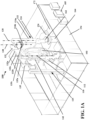
- FIG. 1A illustrates an example of a manufacturing cell 100 of a system for manufacturing a vehicle.
- the manufacturing cell 100 is configured for assembling a frame 103 (see FIG. 1B ) of a vehicle.
- the manufacturing cell 100 includes a positioner 112, a robot carrier 122 and a robot 132.
- the positioner 112 is configured to receive a fixture table 142, where the fixture table 142 is configured to hold the frame 103.
- the term "frame” may also be referred as"space frame”,”smart frame”, “chassis”,”supporting structure", or”supporting components" of a vehicle.
- the robot carrier 122 includes a vertical lift 124, where the vertical lift includes a vertical column 124a and a shelf 124b, where the shelf 124b is movably attached to the vertical column 124a, and extends radially outwards from the vertical column 124a.
- the shelf 124b is movable along a vertical direction.
- the robot 132 is mounted on the shelf l24b and is configured to assemble the frame 103.
- the positioner 112 is configured to support the frame 103 in a vertical position, or a primarily vertical position, during an assembling process of the frame 103.
- the robot carrier 122 may further includes a rotary base 126.
- the vertical lift 124 is attached to the rotary base 126.
- the base 126 has a base central axis 128, where the base 126 is configured to be rotatable around the base central axis 128.
- the robot carrier 122 is configured to support the robot 132. In this embodiment, the robot carrier 122 has 2 degrees of freedom, vertical movement and rotation.
- the robot carrier 122 has an independent rotation of the vertical lift column l24a. Since the base 126 is configured to be rotatable around the base central axis 128, the vertical column 124a mounted on the base 126 is rotatable around the base central axis 128 as well.
- the robot 132 may have various axis configurations.
- the robot 132 may have a robot base 132b and an arm 132a.
- the robot base 132b is mounted on the shelf 124b of the vertical lift 124.
- the robot 132 may have six axes, also called six degrees of freedom.
- the six axis robot 132 allows for greater maneuverability, and can perform a wider variety of manipulations than robots with fewer axes. In other configurations, however, fewer than six axes may be used.
- the robot 132 has a first axis 138 located at the robot base 132b, allows the robot to rotate from side to side.
- the first axis 138 is the central axis 138 of the robot 132.
- the robot 132 is configured to rotate around the robot central axis 138. This axis 138 allows the robot 132 to spin up to or past a full 180 degree range from center, in either direction.
- the robot 132 may have a second axis which allows the lower arm 132a of the robot 132 to extend forward and backward. It is the axis powering the movement of the entire lower arm 132a.
- the robot 132 may have a third axis which extends the robot's reach. It allows the upper arm to be raised and lowered. On some articulated models, it allows the upper arm to reach behind the body, further expanding the work envelope. This axis gives the upper arm the better part access.
- the robot 132 may have a fourth axis which aids in the positioning of the end effector and manipulation of the part to be assembled.
- the robot 132 may further have a fifth axis which allows the wrist of the robot arm to tilt up and down.
- the robot 132 may further have a sixth axis which is the wrist of the robot arm 132a.
- the robot central axis 138 is offset from the base central axis 128, as shown in FIG. 1A .
- the robot base l32b is mounted on the shelf 124b of the vertical lift 124. Since the shelf 124b is extending radially outwards from the base central axis 128, the robot central axis 138 has a distance from the base central axis 128.
- the shelf 124b is also rotatable around the base central axis 138.
- the robot 132 is further rotatable about an arc movement around the base central axis 128, in addition to being rotatable around the first axis 138 of the robot 132.
- This sweeping motion of robot base 132a about the base central axis 128 extends the work area of the robot 132 to include the area on either side, and behind the vertical axis 128.
- the robot 132 is capable of independently moving vertically up and down, rotating from side- to-side, and in a combination of the aforementioned movements. Therefore, the robot 132 is not limited to its own degrees of freedom.
- the robot 132 has a larger work envelope.
- the robot carrier 122 and the robot 132 together have eight degrees of freedom. The more degrees of freedom enables the manufacturer to use fewer robots, which can reduce cost and increase efficiency.
- the robot carrier 122 may include a control unit (not shown).
- the control unit is configured to control the robot carrier 122.
- the manufacturing cell 100 may further include a controller 185, which can be configured to control the robot carrier 122, the robot 132, the positioner 112, and controls for the rest of the system.
- the controller 185 can be configured to control an assembling process of the frame 103, for example, an automatic assembling process. The entire assembling process can be automated with high efficiency and low cost.
- a central control station may communicate to the robot carrier 122 to issue instructions for the assembling process.
- the robot carrier 122 may be authorized to perform certain functions and make certain decisions on its own, while a central station or an on-site server may have control over other, potentially more important decisions which may be conveyed to the robot carrier 122 electronically or otherwise.
- FIG. 1B illustrates an example of the frame 103.
- the frame 103 can includes a plurality of connecting components 101 a, 101 b, 101 c, a plurality of joint members 102, or nodes 102.
- the joint members or nodes may be produced by a 3-D printer.
- Each joint member may be sized and shaped to mate with at least a subset of the plurality of the connecting components 101 a, 101 b, lOlc to form a three- dimensional frame structure 103.
- the plurality of joint members 102 include mounting features, which provide panel mounts for mounting of panels on the three- dimensional frame structure 103.
- the mounting features may be produced by a 3-D printer.
- the frame 103 may form the framework of a vehicle.
- the frame 103 may provide the structure for placement of body panels of the vehicle, where body panels may be door panels, roof panels, floor panels, or any other panels forming the vehicle enclosure.
- the frame 103 may be the structural support for the wheels, drive train, engine block, electrical components, heating and cooling systems, seats, storage space, and other systems.
- the vehicle may be a passenger vehicle capable of carrying at least about 1 or more, 2 or more, 3 or more, 4 or more, 5 or more, 6 or more, 7 or more, 8 or more, ten or more, twenty or more, or thirty or more passengers.
- Examples of vehicles may include, but are not limited to sedans, trucks, buses, vans, minivans, station wagons, RVs, trailers, tractors, go-carts, automobiles, trains, or motorcycles, boats, spacecraft, or airplanes.
- the frame may provide a form factor that matches the form factor of the type of vehicle. Depending on the type of vehicle, the frame may have varying configurations. The frame may have varying levels of complexity. In some instances, a three-dimensional frame may provide an outer framework for the vehicle.
- a three-dimensional frame may provide an inner framework for the vehicle.
- a three-dimensional frame may provide partially inner and partially outer framework for the vehicle.
- the framework may be configured to accept body panels to form a three-dimensional enclosure.
- inner supports or components may be provided.
- the inner supports or components can be connected to the frame through connection to the one or more joint members of the frame.
- Different layouts of multiport nodes and connecting components may be provided to accommodate different vehicle frame/chassis configurations.
- a set of nodes can be arranged to form a single unique frame/chassis design. Alternatively at least a subset of the set of nodes can be used to form a plurality of frame/chassis designs.
- At least a subset of nodes in a set of nodes can be assembled into a first frame/chassis design and then disassembled and reused to form a second frame/chassis design.
- the first frame/chassis design and the second frame/chassis design can be the same or they can be different.
- Nodes may be able to support components in a two or three-dimensional plane.
- the frame may include other types of frame or other features which include nodes, channels to inject adhesives, pick-up features which allow robots to pick up or otherwise manipulate portions or all of the frame, and tooling features built into the frame.
- the frame may be assembled entirely by robots, or by an automatic assembling process.
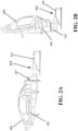
- FIG. 2A is an illustration of a positioner 212 coupled to a fixture table 242, when the fixture table 242 is in one position.
- FIG. 2B illustrates the positioner 212 coupled to the fixture table 242, when the fixture table 242 is in another position.
- the positioner 212 is configured to support the fixture table 242.
- the fixture table 242 is configured to hold the frame 103, and to be coupled to the positioner 212.
- the positioner 212 is configured to perform one or more of lifting the fixture table 242, tilting the fixture table 242, and rotating the fixture table 242.
- the positioner 212 is a 3 -axis positioner, which adds 3 degrees of freedom to the manufacturing cell.
- the positioner 212 lifts the fixture table 242 up and down, from and to the ground.
- the positioner 212 further tilts the fixture table 242 from a horizontal position to a vertical position, and anywhere in between. In some embodiments, it can go beyond the horizontal and vertical positions.
- the positioner 212 can rotate the fixture table 242 around a positional axis 118 (see FIG. 1A ).
- the fixture table 242 may further include a backbone (not shown), which is integrated with the fixture table.
- the backbone is configured to be coupled to the positioner 212 and may facilitate such rotations or other manipulating actions.
- the positioner 212 is capable of performing either independent movements, or dependent movements of all the aforementioned movements.
- the positioner 212 includes a 3-point kinematic mount 215 and a positioner base 219.
- the fixture table 242 may be secured to the positioner 212 with the 3-point kinematic mount 215.
- the positioner 212 may be attached to the fixture table 242 by various fail-safe methods, including bolting or a zero-point quick release mechanism.
- the positioner 212 may include one or more zero point pins to secure the fixture table 242 to the positioner 212.
- a mechanical lock between the fixture table 242 and positioner 212 can be used to securely lock the fixture table 242 to the positioner 212. Therefore, the positioner 212 can support the fixture table 242 at various positions, including a vertical position, a horizontal position, and anywhere in between, as shown in FIG. 2 A and FIG. 2B .
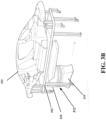
- FIG. 3A illustrates another embodiment of a positioner 312 coupled to a fixture table 342, when the fixture table 342 is holding a frame 103 in a vertical position.
- FIG. 3B illustrates the positioner 312 coupled to the fixture table 342, when the fixture table 342 is in a horizontal position.
- the positioner 312 may further includes a backbone 316.
- the backbone 316 is integrated with the positioner 312.
- the fixture table 342 is configured to be coupled to the backbone 316 of the positioner 312.
- the positioner 312 may further include an actuator 317, a positioner base 318, and a turntable 319.
- the positioner 312 is configured to perform one or more of lifting the fixture table 342, tilting the fixture table 342, and rotating the fixture table 342.
- the positioner 312 is capable of performing either independent movements, or dependent movements of all the aforementioned movements.
- the backbone 316 of the positioner 312 is configured to be movable between a horizontal position and a vertical position.
- the positioner 312 can flip the fixture table 342 from a horizontal position to a vertical position, and vice versa.
- the positioner 212 can rotate the fixture table 342 by rotating the turntable 319.
- the fixture table 342 as shown in FIG. 3A and FIG. 3B is a customized fixture table, which is configured to match different frame of different types of vehicles, or different models of the same type of vehicles.
- the manufacturing cell can be used to manufacture different types of vehicles by using different fixture tables.
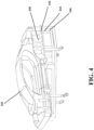
- FIG. 4 is an illustration of a modular fixture table 442 configured to hold a frame 103 of a vehicle.
- the modular fixture table 442 includes a plurality of locating features 444 (e.g., holes) and securement features 446.
- the modular fixture table 442 further includes a plurality of movable support plates 448.
- the plurality of locating features 444 and securement features 446, and the plurality of movable support plates 448 provide the flexibility to match different frame of different types of vehicles, or different models of the same type of vehicles.
- the manufacturing cell 100 can assemble a plurality of frame with minimum tooling changeover (retooling).
- Customized or modular fixture tables can be used to accommodate different frame for a plurality of vehicles.
- the manufacturing cell 100 can serve as a flexible universal constructor for a wide variety of vehicles. The effort for changing to a new model can be reduced, and the cycle for developing a new model can be shortened as well.
- the manufacturing cell 100 is configured for volume production.
- the manufacturing cell 100 may have high robot utilization, where required, for high volumes.
- the manufacturing cell 100 can be configured to be fully automatic, for example. The automatic assembling process can significantly reduce the manufacturing effort of the frame, thereby enabling vehicles with the frame to be produced more efficiently and economically.
- the positioner 112 is configured to support the fixture table 142 in a vertical position during an assembling process of the frame 103.
- Some advantages of the vertical manufacturing cell 100 include better accessibility, increased degrees of freedom, reduced footprint, fewer part transfer, reduced component count, and lower maintenance than conventional assembly or manufacturing technologies.
- the vertical space utilization can be maximized.
- the robots can access the frame from more angles, which can increase the efficiency of an assembling process of the frame 103.
- the manufacturing cell 100 may further include a second robot carrier 125 and a second robot 135. Both robots 132, 135 work together to assemble the frame 103, or parts thereof.
- the second robot carrier 125 may be positioned at an opposite side of the positioner 112 than the robot carrier 122.
- the robot carrier 122 may be positioned at +45 degrees relative to the positioner 112, and the second robot carrier 125 may be positioned at -45 degrees relative to the positioner 112.
- the manufacturing cell 100 may further include one or more robot carriers. There is no limit to the number of robot carriers. There are also many configurations to place the one or more robot carriers. The examples discussed above are only for illustration purpose, and there is no limitation to the relative positions of the one or more robot carriers.
- the manufacturing cell 100 may further include one or more stationary robots 162.
- each of the one or more stationary robots 162 may be placed on a corresponding pedestal 164, which elevates the stationary robot to a desired working height to enable greater accessibility and reach.
- the stationary robots 162 may perform a variety of tasks, such as assembling assemblies, subassemblies, assisting, etc.
- the manufacturing cell 100 may offer twenty -five or more degrees of freedom, redundant or otherwise.
- the robot 132 may offer six degrees of freedom.
- the robot carrier 122 may offer two degrees of freedom.
- the positioner 112 may offer three degrees of freedom.
- the manufacturing cell 100 with one robot and one robot carrier may have eleven degrees of freedom.
- the second robot carrier 125 and the second robot 135 may offer an additional 8 degrees of freedom.
- the manufacturing cell 100 with two robots and two robot carriers may offer a total of nineteen degrees of freedom.
- the manufacturing cell 100 can have a lower number of robots than would otherwise be necessary because of the large number of degrees of freedom.
- the manufacturing cell 100 offers agility and dexterity for assembling a frame of a wide variety of vehicles.
- the manufacturing cell 100 allows for a plurality of robots to be positioned strategically inside the cell, enabling pooled work envelopes.
- the compact footprint of the manufacturing cell 100 further has the advantage of saving space.
- the manufacturing cell 100 may have various dimensions.
- the manufacturing cell 100 may have an area between 37.16 square meter and 334.45 square (400 square feet and 3600 square feet).
- the space of the manufacturing cell 100 can be significantly lower than the conventional assembly line for vehicles.
- the vertical manufacturing cell 100 enables robots to act as fixtures, in place of a customary stationary fixture, to thereby achieve an overall reduction or elimination of fixtures during the assembling process.
- the fixture table may have legs with wheels that enable movement on the floor, while holding the frame within the required tolerance.
- the manufacturing cell 100 can be configured to assemble, bond, fasten, and measure the frame 103.
- the manufacturing cell 100 can be configured to assemble, apply adhesive, bolt, and measure the frame 103.
- the robot 132, 135 can be configured to perform multiple tasks, including, but not being limited to, assembling, bonding, fastening, and measuring the frame.
- the arms 132a, 135a of the robots 132, 135 may be configured to be coupled to a plurality of end effectors. Each of the plurality of end effectors can be configured to perform different functions.
- the plurality of end effectors can be configured to be quickly exchanged.
- the manufacturing cell 100 further includes tool tables 172.
- the tool tables can be configured to hold the plurality of end effectors, or subassemblies, or parts, of the frame 103.
- the manufacturing cell 100 may include an adhesive injection subsystem.
- the robots 132, 135 are further configured to apply an adhesive to bond the frame 103.
- the adhesive injection subsystem may include adhesive injection end effectors 132c, 135c.
- the frame 103 includes a plurality of connecting components 101 a, 101 b, 101 c, a plurality of joint members 102, or nodes 102 ( FIG. 1B ). Each joint member may be sized and shaped to mate with at least a subset of the plurality of the connecting components 101 a, 101 b, lOlc to form a three-dimensional frame structure 103.
- the plurality of joint members 102, or nodes 102 may have built-in adhesive ports.
- the robots 132, 135 of FIG. 1A may be configured to grab adhesive injection end effectors 132c, 135c.
- the arms l32a, 135a of the robots 132, 135 may be configured to be coupled to the adhesive injection end effectors 132c, 135c.
- the manufacturing cell 100 may include one or more fastener drivers (not shown).
- the robots 132, 135 are further configured to install fasteners to the frame 103 by using the fastener drivers.
- the arms 132a, 135a of the robots 132, 135 may be configured to be coupled to end effectors for fastener drivers.
- the one or more fastener drivers may be attached to the arms 132a, 135a of the robots 132, 135, to reach all necessary locations, by leveraging all axes of freedom that the manufacturing cell 100 offers. The number of robots and fastener drivers needed may be minimized because of the better reach and accessibility offered by the increased number of degrees of freedom of the manufacturing cell 100.
- the manufacturing cell 100 may include one or more metrology devices (not shown). Metrology devices may include, for example, a laser scanner.
- the robots 132, 135 are further configured to measure multiple points on the frame 103 to perform a general measurement of the frame 103.
- the arms 132a, 135a of the robots 132, 135 may be configured to be coupled to end effectors for metrology devices.
- the one or more metrology devices may be attached to the arms l32a, 135a of the robots 132, 135.
- the robots 132, 135 may be configured to scan and measure the frame 103.
- the robots 132, 135 may be configured to measure the frame 103 by scanning the frame 103.
- the robots 132, 135 may be configured to measure the frame 103 by probing the frame 103.
- the vertical manufacturing cell 100 may advantageously ensure full access of the frame 103, avoiding need for additional components or hardware (e. g., overhead gantry rail system).
- the manufacturing cell 100 may include one or more subassembly robots and one or more subassembly tables.
- each of the one or more subassembly robots may be configured to assemble a subassembly or subsection of the frame 103 on a corresponding subassembly table.
- the subassembly robots may pass the assembled subassemblies to the robots 132, 135 on the robot carriers 122, 125.
- the robots 132, 135 may assemble the frame 103 from the subassemblies.
- the one or more subassembly robots may enable concurrent assembling and therefore may further reduce the overall time of the assembling process.
- the manufacturing cell 100 may include one or more tool changers.
- the tool changers are configured to exchange the plurality of end effectors for the robots.
- tool changers may be used to switch from specially designed end effectors for assembly, scanning heads for measurements, fastener drivers for bolt installations, and adhesive injection end effectors for adhesive and sealer applications.
- the manufacturing cell 100 may be surrounded by safety barrier 194 with safety sensors, and interlocks.
- the safety barrier 194 enable the fixture table 142 holding the frame 103 to enter the manufacturing cell 100 and exit the manufacturing cell 100, and further provide a safety measure to the manufacturing cell 100.
- the safety sensors may send signals to the controller 185 to safely halt the assembling process. Accordingly, if an individual inadvertently enters the manufacturing cell 100, the controller 185 may safely halt the assembling process which in turn may render stationary the currently moving parts that may otherwise be dangerous and may cause significant harm to the individual. In sum, harm may be avoided using the safety barrier 194.
- the safety barrier 194 includes photoelectric light presence sensors.
- the manufacturing cell 100 offers agility and dexterity with reduced duplication of bonding, fastening, and measurement equipment. Scalability of the manufacturing cell 100 can be accomplished through the addition of derivative manufacturing cells to the vertical manufacturing cell 100, or decoupling of fastening, bonding, and or measurement operations. Scalability can also be achieved through duplication of the manufacturing cells in series or parallel, or a combination of the two. Flexibility can be attained through the robots' use of a virtually unlimited number of customized end effectors and other tools for performing a wide variety of specialized operations on the vehicle.
- FIG. 5 illustrates a flow diagram of a method 500 for manufacturing a vehicle.
- the method 500 for manufacturing a vehicle includes a step 502 of receiving a fixture table by a positioner.
- the method 500 can include supporting the fixture table with the positioner 504.
- the method 500 can further include introducing parts to the fixture table 506.
- the method includes a step 508 of assembling a frame of the vehicle using the parts by a robot in an assembling process inside a manufacturing cell.
- the method 500 further includes a step 510 of controlling the assembling process by a controller.
- the step 504 of supporting the fixture table with the positioner includes supporting the fixture table in a vertical position with the positioner during the assembling process.
- the method 500 includes the step 508 of assembling the frame by a robot inside a manufacturing cell.
- the method 500 may further include moving the robot along a vertical direction by placing the robot on a vertical lift.
- the method 500 may include moving the robot along an arc by placing the vertical lift on a base rotatable around a central base axis.
- the method 500 may include performing one or more of lifting the fixture table, tilting the fixture table, and rotating the fixture table by the positioner.
- the method 500 may include assembling the frame by a second robot.
- the method 500 further includes supporting the frame by the positioner during the assembling process inside the manufacturing cell.
- the method 500 of supporting the frame by the positioner may comprise supporting the frame in a vertical position by the positioner during the assembling process.
- the overhead space can be utilized.
- the robots can access the frame from many angles, which can increase the efficiency of the assembling process of the frame.
- the method 500 further includes a step 510 of controlling the assembling process by a controller.
- the entire assembling process of assembling the frame may include high robot utilization, and can be fully automated in some embodiments. Further attributes and advantages of the controlling step 510 are described throughout this disclosure.
- the method 500 may include applying an adhesive to bond together sections of the frame by the robot during the assembling process inside the manufacturing cell. Further, the method 500 may include installing fasteners to the frame by the robot using a fastener driver during the assembling process inside the manufacturing cell. The method 500 may also include measuring multiple points on the frame for measurement of the frame by the robot through a metrology device inside the manufacturing cell during the assembling process. The method 500 may include using a safety sensor to provide safety measure to the manufacturing cell. The method 500 may also include assembling one or more subassemblies of the frame by one or more subassembly robots on one or more subassembly tables inside the manufacturing cell. It will be appreciated that the above are merely non-exhaustive examples of the wide variety of tasks that the robots or other devices can undertake during the assembling process.
- the systems and methods disclosed herein are modular in design and flexible for manufacturing a wide variety of vehicles. Newly developed products only require minimal retooling, resulting in significantly lower new product development efforts, and a reduced R&D cycle.
- the manufacturing cell based systems and methods involve high robot utilization and a potentially fully automatic manufacturing process, which lead to the possibility of cost effective mass production.
- the manufacturing cell based systems and methods significantly lower the manufacturing efforts of the vehicles.
- the frame design results in weight savings and enables easier repair and service.
- the manufacturing cell enables easy assembling in a small space, which significantly saves overall manufacturing space. Therefore, the manufacturing cell based systems and methods provide a new platform for manufacturing vehicles.
Landscapes
- Engineering & Computer Science (AREA)
- Mechanical Engineering (AREA)
- Robotics (AREA)
- Chemical & Material Sciences (AREA)
- Combustion & Propulsion (AREA)
- Transportation (AREA)
- Manufacturing & Machinery (AREA)
- General Engineering & Computer Science (AREA)
- Automatic Assembly (AREA)
Claims (16)
- Fertigungszelle (100), die für die Montage eines Rahmens (103) eines Fahrzeugs konfiguriert ist, wobei die Fertigungszelle Folgendes umfasst: einen Positionierer, der so konfiguriert ist, dass er einen Befestigungstisch aufnimmt, der so konfiguriert ist, dass er den Rahmen hält, einen Roboterträger, der einen an einer Basis befestigten vertikalen Heber aufweist, wobei der vertikale Heber eine vertikale Säule und ein Regal umfasst, einen Roboter, der auf dem Regal montiert ist und so konfiguriert ist, dass er den Rahmen montiert, dadurch gekennzeichnet, dass:das Regal (124b) beweglich an der vertikalen Säule (124a) angebracht ist und entlang einer vertikalen Richtung bewegt werden kann und wobei die Basis (126) eine Basismittelachse aufweist, wobei der vertikale Heber (124b) und die Basis (126) so konfiguriert sind, dass sie um die Basismittelachse drehbar sind; unddadurch, dass der Positionierer (112) so konfiguriert ist, dass er den Befestigungstisch (142) nach oben und unten hebt und den Befestigungstisch (142) kippt, um den Rahmen (103) während eines Montageprozesses des Rahmens (103) irgendwo zwischen einer vertikalen Position und einer horizontalen Position zu stützen.
- Fertigungszelle (100) nach Anspruch 1, wobei der Roboter (132) sechs Freiheitsgrade hat und wobei der Roboterträger und der Roboter (132) zusammen acht Freiheitsgrade haben.
- Fertigungszelle (100) nach Anspruch 1, wobei der Roboter (132) eine Robotermittelachse aufweist, wobei der Roboter (132) so konfiguriert ist, dass er sich um die Robotermittelachse dreht.
- Fertigungszelle (100) nach Anspruch 4, wobei die Robotermittelachse von der Basismittelachse versetzt ist, so dass der Roboter (132) ferner um eine Bogenbewegung um die Basismittelachse drehbar ist.
- Fertigungszelle (100) nach Anspruch 1, wobei der Positionierer (112) so konfiguriert ist, dass er den Vorrichtungstisch (142, 242) dreht.
- Fertigungszelle (100) nach Anspruch 1, wobei der Positionierer (112) außerdem eine kinematische Dreipunktaufhängung umfasst.
- Fertigungszelle (100) nach Anspruch 1, die ferner eine mechanische Verriegelung umfasst, wobei die mechanische Verriegelung so konfiguriert ist, dass sie den Vorrichtungstisch (142, 242) an der Positioniervorrichtung (112) verriegelt, und wobei die Positioniervorrichtung (112) so konfiguriert ist, dass sie den Vorrichtungstisch (142, 242) in der vertikalen Position, der horizontalen Position und an einer beliebigen Stelle zwischen der vertikalen Position und der horizontalen Position hält.
- Fertigungszelle (100) nach Anspruch 1, wobei der Positionierer (112) ferner ein Rückgrat umfasst und wobei das Rückgrat so konfiguriert ist, dass es von der horizontalen Position in die vertikale Position bewegt werden kann.
- Fertigungszelle (100) nach Anspruch 1, wobei der Vorrichtungstisch (142, 242) ferner ein Rückgrat umfasst und wobei das Rückgrat so konfiguriert ist, dass es mit dem Positionierer (112) gekoppelt ist.
- Fertigungszelle (100) nach Anspruch 1, wobei der Roboter (132) ferner ein Klebstoffinjektions-Teilsystem umfasst, das so konfiguriert ist, dass es einen Klebstoff aufträgt, um den Rahmen zu verbinden, wobei das Klebstoffinjektions-Teilsystem eine Vielzahl von Klebstoffinjektions-Endeffektoren umfasst.
- Fertigungszelle (100) nach Anspruch 1, die ferner einen Treiber für Befestigungsmittel umfasst, wobei der Roboter (132) ferner einen Arm umfasst und wobei der Treiber für Befestigungsmittel an dem Arm des Roboters (132) angebracht ist, wobei der Roboter (132) ferner so konfiguriert ist, dass er unter Verwendung des Treibers für Befestigungsmittel Befestigungsmittel an dem Rahmen anbringt.
- Fertigungszelle (100) nach Anspruch 1, die ferner eine Messvorrichtung umfasst, wobei der Roboter (132) ferner einen Arm umfasst und wobei die Messvorrichtung an dem Arm des Roboters angebracht ist, wobei der Roboter (132) ferner so konfiguriert ist, dass er mehrere Punkte auf dem Rahmen zur Vermessung des Rahmens unter Verwendung der Messvorrichtung misst.
- Fertigungszelle (100) nach Anspruch 1, die ferner einen Werkzeugtisch, einen Werkzeugwechsler und eine Vielzahl von Endeffektoren umfasst, wobei der Werkzeugtisch so konfiguriert ist, dass er die Vielzahl von Endeffektoren hält und wobei der Werkzeugwechsler so konfiguriert ist, dass er die Vielzahl von Endeffektoren für den Roboter (132) austauscht.
- Fertigungszelle (100) nach Anspruch 1, die ferner einen Sicherheitssensor umfasst, der so konfiguriert ist, dass er eine Sicherheitsmaßnahme für die Fertigungszelle (100) bereitstellt.
- Fertigungszelle (100) nach Anspruch 1, die ferner einen oder mehrere Unteranordnungsroboter und einen oder mehrere Unteranordnungstische umfasst, wobei jeder der einen oder mehreren Unteranordnungsroboter so konfiguriert ist, dass er eine Unteranordnung des Rahmens auf einem entsprechenden des einen oder der mehreren Unteranordnungstische montiert.
- Fertigungszelle (100) nach Anspruch 1, wobei der Vorrichtungstisch einen modularen Vorrichtungstisch mit einer Vielzahl von Fixier- und Sicherungsmerkmalen und einer Vielzahl von beweglichen Stützplatten umfasst.
Applications Claiming Priority (2)
| Application Number | Priority Date | Filing Date | Title |
|---|---|---|---|
| US15/925,672 US11254381B2 (en) | 2018-03-19 | 2018-03-19 | Manufacturing cell based vehicle manufacturing system and method |
| PCT/US2019/021544 WO2019182780A1 (en) | 2018-03-19 | 2019-03-11 | Manufacturing cell based vehicle manufacturing systems and methods |
Publications (3)
| Publication Number | Publication Date |
|---|---|
| EP3768581A1 EP3768581A1 (de) | 2021-01-27 |
| EP3768581A4 EP3768581A4 (de) | 2022-01-05 |
| EP3768581B1 true EP3768581B1 (de) | 2024-06-12 |
Family
ID=67905054
Family Applications (1)
| Application Number | Title | Priority Date | Filing Date |
|---|---|---|---|
| EP19772033.7A Active EP3768581B1 (de) | 2018-03-19 | 2019-03-11 | Fertigungszelle für den zusammenbau eines fahrzeugrahmens |
Country Status (4)
| Country | Link |
|---|---|
| US (1) | US11254381B2 (de) |
| EP (1) | EP3768581B1 (de) |
| CN (2) | CN110282049A (de) |
| WO (1) | WO2019182780A1 (de) |
Families Citing this family (10)
| Publication number | Priority date | Publication date | Assignee | Title |
|---|---|---|---|---|
| US11254381B2 (en) * | 2018-03-19 | 2022-02-22 | Divergent Technologies, Inc. | Manufacturing cell based vehicle manufacturing system and method |
| US12280554B2 (en) * | 2019-11-21 | 2025-04-22 | Divergent Technologies, Inc. | Fixtureless robotic assembly |
| US11427351B2 (en) * | 2019-12-06 | 2022-08-30 | The Boeing Company | Carrier and operational frame system and methods of assembling a structure |
| US20220089237A1 (en) * | 2020-06-16 | 2022-03-24 | Arrival Ltd. | Robotic production environment for vehicles |
| US11498285B2 (en) * | 2020-09-30 | 2022-11-15 | Ford Global Technologies, Llc | Agile robotic headlamp assembly with sonic fastening and injected lens adhesive |
| CN118829537A (zh) | 2022-01-25 | 2024-10-22 | 戴弗根特技术有限公司 | 用于结构装配的基于测量的校正 |
| US12130196B2 (en) * | 2022-04-01 | 2024-10-29 | Ford Global Technologies, Llc | Methods and systems for verifying the alignment of vehicle devices |
| CN115382730B (zh) * | 2022-09-15 | 2023-11-07 | 歌尔股份有限公司 | 组装设备 |
| US20240399517A1 (en) * | 2023-05-31 | 2024-12-05 | GM Global Technology Operations LLC | Manufacturing system including mobile cart with trunnion axis control |
| CN117600023B (zh) * | 2023-12-11 | 2025-01-21 | 深圳市星禾宏泰自动化设备有限公司 | 一种汽车灯点胶组装加工设备及其点胶组装方法 |
Family Cites Families (337)
| Publication number | Priority date | Publication date | Assignee | Title |
|---|---|---|---|---|
| US2884242A (en) * | 1955-09-20 | 1959-04-28 | British Oxygen Co Ltd | Welding positioners |
| US3370723A (en) * | 1965-09-20 | 1968-02-27 | Anchor Steel & Convevor Compan | Work transfer apparatus |
| US3905495A (en) * | 1974-09-05 | 1975-09-16 | Planet Corp | Frame handler with improved carriage assembly |
| US4238169A (en) * | 1978-05-08 | 1980-12-09 | Clark Equipment Company | Handling device for vehicle frames |
| JPS57199718A (en) * | 1981-05-29 | 1982-12-07 | Fukui Kikai Kk | Suspending and arranging equipment for pressed products |
| JPS62238099A (ja) * | 1986-04-08 | 1987-10-19 | Honda Motor Co Ltd | 被溶接物の保持装置 |
| JPS63260681A (ja) | 1987-04-17 | 1988-10-27 | Honda Motor Co Ltd | 二輪車車体の組立方法 |
| MX163623B (es) * | 1987-04-17 | 1992-06-08 | Honda Motor Co Ltd | Metodo para ensamblar un cuerpo de vehiculo de un vehiculo de dos ruedas y un aparato de ensamble para el mismo |
| JPH02117481A (ja) | 1988-10-26 | 1990-05-01 | Honda Motor Co Ltd | ワーク搬送組付装置 |
| JPH02220775A (ja) | 1989-02-23 | 1990-09-03 | Honda Motor Co Ltd | 二輪車車体の組立装置 |
| US5125149A (en) * | 1989-04-28 | 1992-06-30 | Canon Kabushiki Kaisha | Method of accessing and assembling parts in an assembly apparatus incorporating mobile robots |
| US5203226A (en) | 1990-04-17 | 1993-04-20 | Toyoda Gosei Co., Ltd. | Steering wheel provided with luminous display device |
| IT1248419B (it) * | 1990-06-15 | 1995-01-16 | Comau Spa | Stazione di assemblaggio di struttura di lamiera stampata provvista di robot di saldatura utilizzabili anche per il controllo periodico delle attrezzature utilizzate nella stazione. |
| JPH0755667B2 (ja) * | 1990-07-20 | 1995-06-14 | 株式会社神戸製鋼所 | 自動車塗装装置 |
| JPH0569249A (ja) * | 1991-09-05 | 1993-03-23 | Suzuki Motor Corp | 車輪自動搭載システム |
| JPH0755667A (ja) * | 1993-08-20 | 1995-03-03 | Alithium:Kk | 発光分析用試料の切削方法および該方法に使用する治具 |
| DE29507827U1 (de) | 1995-05-16 | 1995-07-20 | Edag Engineering + Design Ag, 36039 Fulda | Zum Zuführen von Schweißbolzen zu einer Schweißpistole bestimmte Zuführvorrichtung |
| DE19518175A1 (de) | 1995-05-19 | 1996-11-21 | Edag Eng & Design Ag | Verfahren zum automatischen Einbau eines Bauteils einer Kraftfahrzeugkarosserie |
| DE19519643B4 (de) | 1995-05-30 | 2005-09-22 | Edag Engineering + Design Ag | Behälter-Wechselvorrichtung |
| US5990444A (en) | 1995-10-30 | 1999-11-23 | Costin; Darryl J. | Laser method and system of scribing graphics |
| US6252196B1 (en) | 1996-10-11 | 2001-06-26 | Technolines Llc | Laser method of scribing graphics |
| US5742385A (en) | 1996-07-16 | 1998-04-21 | The Boeing Company | Method of airplane interiors assembly using automated rotating laser technology |
| WO1998024958A1 (fr) | 1996-12-05 | 1998-06-11 | Teijin Limited | Procede de moulage d'agregats de fibres |
| US6193142B1 (en) * | 1996-12-25 | 2001-02-27 | Nissan Motor Co., Ltd. | Assembling apparatus assembling body side of automotive vehicle and assembling method thereof |
| US6010155A (en) | 1996-12-31 | 2000-01-04 | Dana Corporation | Vehicle frame assembly and method for manufacturing same |
| US6140602A (en) | 1997-04-29 | 2000-10-31 | Technolines Llc | Marking of fabrics and other materials using a laser |
| US6339874B2 (en) * | 1997-08-28 | 2002-01-22 | Nissan Motor Co., Ltd. | Assembling apparatus assembling body side of automotive vehicle |
| SE509041C2 (sv) | 1997-10-23 | 1998-11-30 | Ssab Hardtech Ab | Krockskyddsbalk för fordon |
| DE19907015A1 (de) | 1999-02-18 | 2000-08-24 | Edag Eng & Design Ag | In Fertigungslinien für Kraftfahrzeuge einsetzbare Spannvorrichtung und Fertigungslinie mit einer solchen Spannvorrichtung |
| DE29909047U1 (de) * | 1999-05-22 | 2000-11-23 | KUKA Schweissanlagen GmbH, 86165 Augsburg | Positioniervorrichtung für Werkstückträger oder Werkstücke |
| US6811744B2 (en) | 1999-07-07 | 2004-11-02 | Optomec Design Company | Forming structures from CAD solid models |
| US6391251B1 (en) | 1999-07-07 | 2002-05-21 | Optomec Design Company | Forming structures from CAD solid models |
| US6365057B1 (en) | 1999-11-01 | 2002-04-02 | Bmc Industries, Inc. | Circuit manufacturing using etched tri-metal media |
| US6468439B1 (en) | 1999-11-01 | 2002-10-22 | Bmc Industries, Inc. | Etching of metallic composite articles |
| US6409930B1 (en) | 1999-11-01 | 2002-06-25 | Bmc Industries, Inc. | Lamination of circuit sub-elements while assuring registration |
| US6318642B1 (en) | 1999-12-22 | 2001-11-20 | Visteon Global Tech., Inc | Nozzle assembly |
| US6585151B1 (en) | 2000-05-23 | 2003-07-01 | The Regents Of The University Of Michigan | Method for producing microporous objects with fiber, wire or foil core and microporous cellular objects |
| ITRM20010289A1 (it) * | 2000-05-30 | 2002-11-28 | Honda Motor Co Ltd | Procedimento ed apparecchiatura per l'assemblaggio del telaio di un veicolo, in particolare per motocicli. |
| US6919035B1 (en) | 2001-05-18 | 2005-07-19 | Ensci Inc. | Metal oxide coated polymer substrates |
| JP3889940B2 (ja) | 2001-06-13 | 2007-03-07 | 株式会社東海理化電機製作所 | 金型装置、金型装置の使用方法、及び金型装置の共用方法 |
| KR100883320B1 (ko) | 2001-08-31 | 2009-02-11 | 아데아게 엔지니어링 + 디자인 악티엔게젤샤프트 | 플랜지 절곡용 롤링 절곡기 및 롤링 절곡방법 |
| US6926970B2 (en) | 2001-11-02 | 2005-08-09 | The Boeing Company | Apparatus and method for forming weld joints having compressive residual stress patterns |
| US6644721B1 (en) | 2002-08-30 | 2003-11-11 | Ford Global Technologies, Llc | Vehicle bed assembly |
| US6899377B2 (en) * | 2002-09-24 | 2005-05-31 | Ford Motor Company | Vehicle body |
| JP3839783B2 (ja) * | 2003-03-25 | 2006-11-01 | 本田技研工業株式会社 | 車体フレーム用位置決め治具装置 |
| DE10325906B4 (de) | 2003-06-05 | 2007-03-15 | Erwin Martin Heberer | Vorrichtung zur Abschirmung von kohärenter elektromagnetischer Strahlung sowie Laserkabine mit einer solchen Vorrichtung |
| DE102004014662A1 (de) | 2004-03-25 | 2005-10-13 | Audi Ag | Anordnung mit einer Fahrzeug-Sicherung und einem Analog/Digital-Wandler |
| US7745293B2 (en) | 2004-06-14 | 2010-06-29 | Semiconductor Energy Laboratory Co., Ltd | Method for manufacturing a thin film transistor including forming impurity regions by diagonal doping |
| DE502005001712D1 (de) | 2004-09-24 | 2007-11-29 | Edag Eng & Design Ag | Bördelvorrichtung und Bördelverfahren mit Bauteilschutz |
| JP4541091B2 (ja) * | 2004-10-04 | 2010-09-08 | 本田技研工業株式会社 | 加工搬送装置 |
| US20060108783A1 (en) | 2004-11-24 | 2006-05-25 | Chi-Mou Ni | Structural assembly for vehicles and method of making same |
| DE102005004474B3 (de) | 2005-01-31 | 2006-08-31 | Edag Engineering + Design Ag | Bördelvorrichtung und Bördelverfahren zum Umlegen eines Bördelstegs eines Bauteils um eine Bördelkante |
| DE102005030944B4 (de) | 2005-06-30 | 2007-08-02 | Edag Engineering + Design Ag | Verfahren und Vorrichtung zum Fügen von Fügestrukturen, insbesondere in der Montage von Fahrzeugbauteilen |
| EP1928963B1 (de) | 2005-09-28 | 2012-03-21 | Dip Tech. Ltd. | Tinte mit einer mit dem ätzen vergleichbaren wirkung zum drucken auf keramischen oberflächen |
| US7716802B2 (en) | 2006-01-03 | 2010-05-18 | The Boeing Company | Method for machining using sacrificial supports |
| DE102006014282A1 (de) | 2006-03-28 | 2007-10-04 | Edag Engineering + Design Ag | Spannvorrichtung zum Aufnehmen und Spannen von Bauteilen |
| DE102006014279A1 (de) | 2006-03-28 | 2007-10-04 | Edag Engineering + Design Ag | Spannvorrichtung zum Aufnehmen und Spannen von Bauteilen |
| JP2007292048A (ja) | 2006-03-29 | 2007-11-08 | Yamaha Motor Co Ltd | 鞍乗型車両用排気装置および鞍乗型車両 |
| EP2016620A2 (de) | 2006-04-17 | 2009-01-21 | Omnivision Cdm Optics, Inc. | Als array angeordnetes bildgebungssystem und entsprechende verfahren |
| DE102006021755A1 (de) | 2006-05-10 | 2007-11-15 | Edag Engineering + Design Ag | Energiestrahl-Löten oder -Schweißen von Bauteilen |
| JP2007317750A (ja) | 2006-05-23 | 2007-12-06 | Matsushita Electric Ind Co Ltd | 撮像装置 |
| KR100775147B1 (ko) * | 2006-06-27 | 2007-11-12 | 현대자동차주식회사 | 로봇 로딩 행거장치 |
| DE102006038795A1 (de) | 2006-08-18 | 2008-03-20 | Fft Edag Produktionssysteme Gmbh & Co. Kg | Überwachungsvorrichtung für eine Laserbearbeitungsvorrichtung |
| EP1900709B1 (de) | 2006-09-14 | 2010-06-09 | Ibiden Co., Ltd. | Verfahren zur Herstellung eines Wabenkörpers und Zusammensetzung für Sinterwabenkörper |
| JP2008074251A (ja) | 2006-09-21 | 2008-04-03 | Nissan Motor Co Ltd | 車両フレーム反転装置及び車両フレームの反転方法 |
| DE202006018552U1 (de) | 2006-12-08 | 2007-02-22 | Edag Engineering + Design Ag | Bördelhandgerät |
| US7344186B1 (en) | 2007-01-08 | 2008-03-18 | Ford Global Technologies, Llc | A-pillar structure for an automotive vehicle |
| DE102007002856B4 (de) | 2007-01-15 | 2012-02-09 | Edag Gmbh & Co. Kgaa | Vorrichtung zum Bördeln und Schweißen oder Löten von Bauteilen |
| EP1949981B1 (de) | 2007-01-18 | 2015-04-29 | Toyota Motor Corporation | Zusammenbau von Blechteilen |
| DE202007002364U1 (de) * | 2007-02-14 | 2008-06-19 | Kuka Systems Gmbh | Positioniereinrichtung |
| DE202007003110U1 (de) | 2007-03-02 | 2007-08-02 | Edag Engineering + Design Ag | Automobil mit erleichtertem Fahrgastausstieg |
| US7710347B2 (en) | 2007-03-13 | 2010-05-04 | Raytheon Company | Methods and apparatus for high performance structures |
| US7798316B2 (en) * | 2007-04-11 | 2010-09-21 | Chrysler Group Llc | Robotic frame handling system |
| DE102007022102B4 (de) | 2007-05-11 | 2014-04-10 | Fft Edag Produktionssysteme Gmbh & Co. Kg | Bördeln von Bauteilen in Serienfertigungen mit kurzen Taktzeiten |
| DE202007007838U1 (de) | 2007-06-01 | 2007-09-13 | Edag Engineering + Design Ag | Rollbördelwerkzeug |
| US8655429B2 (en) * | 2007-06-29 | 2014-02-18 | Accuray Incorporated | Robotic arm for a radiation treatment system |
| WO2009012102A1 (en) | 2007-07-13 | 2009-01-22 | Advanced Ceramics Manufacturing, Llc | Aggregate-based mandrels for composite part production and composite part production methods |
| JP4478200B2 (ja) | 2007-07-20 | 2010-06-09 | 新日本製鐵株式会社 | ハイドロフォーム加工方法及びハイドロフォーム加工部品 |
| US9818071B2 (en) | 2007-12-21 | 2017-11-14 | Invention Science Fund I, Llc | Authorization rights for operational components |
| US9626487B2 (en) | 2007-12-21 | 2017-04-18 | Invention Science Fund I, Llc | Security-activated production device |
| US8429754B2 (en) | 2007-12-21 | 2013-04-23 | The Invention Science Fund I, Llc | Control technique for object production rights |
| US9128476B2 (en) | 2007-12-21 | 2015-09-08 | The Invention Science Fund I, Llc | Secure robotic operational system |
| US8286236B2 (en) | 2007-12-21 | 2012-10-09 | The Invention Science Fund I, Llc | Manufacturing control system |
| US8752166B2 (en) | 2007-12-21 | 2014-06-10 | The Invention Science Fund I, Llc | Security-activated operational components |
| US9071436B2 (en) | 2007-12-21 | 2015-06-30 | The Invention Science Fund I, Llc | Security-activated robotic system |
| DE102008003067B4 (de) | 2008-01-03 | 2013-05-29 | Edag Gmbh & Co. Kgaa | Verfahren und Biegewerkzeug zum Biegen eines Werkstücks |
| US7908922B2 (en) | 2008-01-24 | 2011-03-22 | Delphi Technologies, Inc. | Silicon integrated angular rate sensor |
| DE102008008306A1 (de) | 2008-02-07 | 2009-08-13 | Edag Gmbh & Co. Kgaa | Drehtisch |
| DE102008013591B4 (de) | 2008-03-11 | 2010-02-18 | Edag Gmbh & Co. Kgaa | Werkzeug, Anlage und Verfahren zur Herstellung eines Kabelbaums |
| US8157155B2 (en) * | 2008-04-03 | 2012-04-17 | Caterpillar Inc. | Automated assembly and welding of structures |
| DE102008047800B4 (de) | 2008-05-09 | 2021-11-18 | Fft Produktionssysteme Gmbh & Co. Kg | Verfahren und Werkzeug zur Herstellung einer Fixierverbindung an formschlüssig gefügten Bauteilen |
| ES2818918T3 (es) | 2008-05-21 | 2021-04-14 | Fft Edag Produktionssysteme Gmbh & Co Kg | Unión de componentes sin marcos de fijación |
| WO2009154484A2 (en) | 2008-06-20 | 2009-12-23 | Business Intelligence Solutions Safe B.V. | Methods, apparatus and systems for data visualization and related applications |
| US8383028B2 (en) | 2008-11-13 | 2013-02-26 | The Boeing Company | Method of manufacturing co-molded inserts |
| US8452073B2 (en) | 2009-04-08 | 2013-05-28 | The United States Of America As Represented By The Administrator Of The National Aeronautics And Space Administration | Closed-loop process control for electron beam freeform fabrication and deposition processes |
| DE102009018619B4 (de) | 2009-04-27 | 2014-07-17 | Fft Edag Produktionssysteme Gmbh & Co. Kg | Roboterabstützung |
| DE102009018618B4 (de) | 2009-04-27 | 2018-09-06 | Fft Produktionssysteme Gmbh & Co. Kg | Spannvorrichtung, Anlage und Verfahren zur Bearbeitung wechselnder Bauteiltypen |
| DE102009024344B4 (de) | 2009-06-09 | 2011-02-24 | Edag Gmbh & Co. Kgaa | Verfahren und Werkzeug zum Bördeln eines Werkstücks |
| DE202009012432U1 (de) | 2009-09-15 | 2010-01-28 | Edag Gmbh & Co. Kgaa | Karosseriebauteil |
| US8354170B1 (en) | 2009-10-06 | 2013-01-15 | Hrl Laboratories, Llc | Elastomeric matrix composites |
| US8610761B2 (en) | 2009-11-09 | 2013-12-17 | Prohectionworks, Inc. | Systems and methods for optically projecting three-dimensional text, images and/or symbols onto three-dimensional objects |
| US8606540B2 (en) | 2009-11-10 | 2013-12-10 | Projectionworks, Inc. | Hole measurement apparatuses |
| US8755923B2 (en) | 2009-12-07 | 2014-06-17 | Engineering Technology Associates, Inc. | Optimization system |
| US8686997B2 (en) | 2009-12-18 | 2014-04-01 | Sassault Systemes | Method and system for composing an assembly |
| EP2383669B1 (de) | 2010-04-02 | 2018-07-11 | Dassault Systèmes | Entwurf eines Teils, das durch parallele geodätische Kurven modelliert wird |
| CN103384898A (zh) | 2010-06-21 | 2013-11-06 | 约翰·吉利斯 | 计算机实现的工具箱系统和方法 |
| US8289352B2 (en) | 2010-07-15 | 2012-10-16 | HJ Laboratories, LLC | Providing erasable printing with nanoparticles |
| US8978535B2 (en) | 2010-08-11 | 2015-03-17 | Massachusetts Institute Of Technology | Articulating protective system for resisting mechanical loads |
| EP2799150B1 (de) | 2013-05-02 | 2016-04-27 | Hexagon Technology Center GmbH | Graphisches Auftragssystem |
| US9672550B2 (en) | 2010-09-24 | 2017-06-06 | Amazon Technologies, Inc. | Fulfillment of orders for items using 3D manufacturing on demand |
| US9858604B2 (en) | 2010-09-24 | 2018-01-02 | Amazon Technologies, Inc. | Vendor interface for item delivery via 3D manufacturing on demand |
| US9898776B2 (en) | 2010-09-24 | 2018-02-20 | Amazon Technologies, Inc. | Providing services related to item delivery via 3D manufacturing on demand |
| US9684919B2 (en) | 2010-09-24 | 2017-06-20 | Amazon Technologies, Inc. | Item delivery using 3D manufacturing on demand |
| US9566758B2 (en) | 2010-10-19 | 2017-02-14 | Massachusetts Institute Of Technology | Digital flexural materials |
| US8442686B2 (en) * | 2011-01-31 | 2013-05-14 | Toyota Jidosha Kabushiki Kaisha | Articulated arm robot, control method and control program |
| AU2012214512B2 (en) | 2011-02-07 | 2015-11-19 | Ion Geophysical Corporation | Method and apparatus for sensing underwater signals |
| EP2495292B1 (de) | 2011-03-04 | 2013-07-24 | FFT EDAG Produktionssysteme GmbH & Co. KG | Fügeflächenvorbehandlungsvorrichtung und Fügeflächenvorbehandlungsverfahren |
| CN103717378B (zh) | 2011-06-02 | 2016-04-27 | A·雷蒙德公司 | 通过三维印刷制造的紧固件 |
| US9246299B2 (en) | 2011-08-04 | 2016-01-26 | Martin A. Stuart | Slab laser and amplifier |
| WO2013112217A2 (en) | 2011-10-31 | 2013-08-01 | California Institute Of Technology | Methods for fabricating gradient alloy articles with multi-functional properties |
| KR101305189B1 (ko) * | 2011-11-07 | 2013-09-12 | 기아자동차주식회사 | 차량용 패널 클램핑 장치 |
| US10011089B2 (en) | 2011-12-31 | 2018-07-03 | The Boeing Company | Method of reinforcement for additive manufacturing |
| DE102012101939A1 (de) | 2012-03-08 | 2013-09-12 | Klaus Schwärzler | Verfahren und Vorrichtung zum schichtweisen Aufbau eines Formkörpers |
| JP5571724B2 (ja) | 2012-03-12 | 2014-08-13 | 株式会社ラインワークス | ワーク搭載装置へのワーク搭載方法、ワーク搭載装置からのワーク取外し方法、ワーク搭載装置用ワーク保持具、ワーク搭載装置用ワーク支持具及びワーク搭載システム |
| US9566742B2 (en) | 2012-04-03 | 2017-02-14 | Massachusetts Institute Of Technology | Methods and apparatus for computer-assisted spray foam fabrication |
| JP2013237121A (ja) * | 2012-05-15 | 2013-11-28 | Fanuc Ltd | ロボットの動作範囲を拡張するロボット用旋回装置 |
| WO2013173733A1 (en) | 2012-05-18 | 2013-11-21 | 3D Systems, Inc. | Support structures and deposition techniques for 3d printing |
| US8873238B2 (en) | 2012-06-11 | 2014-10-28 | The Boeing Company | Chassis system and method for holding and protecting electronic modules |
| US9533526B1 (en) | 2012-06-15 | 2017-01-03 | Joel Nevins | Game object advances for the 3D printing entertainment industry |
| WO2013192599A1 (en) | 2012-06-21 | 2013-12-27 | Massachusetts Institute Of Technology | Methods and apparatus for digital material skins |
| US9672389B1 (en) | 2012-06-26 | 2017-06-06 | The Mathworks, Inc. | Generic human machine interface for a graphical model |
| EP2689865B1 (de) | 2012-07-27 | 2016-09-14 | FFT Produktionssysteme GmbH & Co. KG | Bördelpresse |
| EP2880638A1 (de) | 2012-07-30 | 2015-06-10 | Materialise N.V. | Systeme und verfahren zur herstellung und verwendung von biegekarten für objektentwürfe |
| US9534311B2 (en) * | 2012-08-03 | 2017-01-03 | Fanuc America Corporation | Robotic pretreatment and primer electrodeposition system |
| US8437513B1 (en) | 2012-08-10 | 2013-05-07 | EyeVerify LLC | Spoof detection for biometric authentication |
| US10029415B2 (en) | 2012-08-16 | 2018-07-24 | Stratasys, Inc. | Print head nozzle for use with additive manufacturing system |
| CN103801888B (zh) * | 2012-11-12 | 2015-12-23 | 宁波如意股份有限公司 | 升降式手动托盘车自动化焊接装置 |
| US9389315B2 (en) | 2012-12-19 | 2016-07-12 | Basf Se | Detector comprising a transversal optical sensor for detecting a transversal position of a light beam from an object and a longitudinal optical sensor sensing a beam cross-section of the light beam in a sensor region |
| US9329020B1 (en) | 2013-01-02 | 2016-05-03 | Lockheed Martin Corporation | System, method, and computer program product to provide wireless sensing based on an aggregate magnetic field reading |
| US9244986B2 (en) | 2013-01-11 | 2016-01-26 | Buckyball Mobile, Inc. | Method and system for interactive geometric representations, configuration and control of data |
| US9609755B2 (en) | 2013-01-17 | 2017-03-28 | Hewlett-Packard Development Company, L.P. | Nanosized particles deposited on shaped surface geometries |
| US9626489B2 (en) | 2013-03-13 | 2017-04-18 | Intertrust Technologies Corporation | Object rendering systems and methods |
| US20140277669A1 (en) | 2013-03-15 | 2014-09-18 | Sikorsky Aircraft Corporation | Additive topology optimized manufacturing for multi-functional components |
| US9764415B2 (en) | 2013-03-15 | 2017-09-19 | The United States Of America As Represented By The Administrator Of Nasa | Height control and deposition measurement for the electron beam free form fabrication (EBF3) process |
| US9555580B1 (en) | 2013-03-21 | 2017-01-31 | Temper Ip, Llc. | Friction stir welding fastener |
| US9126365B1 (en) | 2013-03-22 | 2015-09-08 | Markforged, Inc. | Methods for composite filament fabrication in three dimensional printing |
| CA3121870A1 (en) | 2013-03-22 | 2014-09-25 | Markforged, Inc. | Three dimensional printing |
| US9186848B2 (en) | 2013-03-22 | 2015-11-17 | Markforged, Inc. | Three dimensional printing of composite reinforced structures |
| US9149988B2 (en) | 2013-03-22 | 2015-10-06 | Markforged, Inc. | Three dimensional printing |
| US9156205B2 (en) | 2013-03-22 | 2015-10-13 | Markforged, Inc. | Three dimensional printer with composite filament fabrication |
| WO2014169238A1 (en) | 2013-04-11 | 2014-10-16 | Digimarc Corporation | Methods for object recognition and related arrangements |
| EP2989140B1 (de) | 2013-04-26 | 2017-05-24 | DSM IP Assets B.V. | Vinylfunktionalisierte urethanharze für pulverbeschichtungszusammensetzungen |
| ES2556564T3 (es) | 2013-05-22 | 2016-01-18 | Fft Produktionssysteme Gmbh & Co. Kg | Ensamblaje de una pieza de trabajo con una soldadura de ensamblaje escondida |
| EP2810749B1 (de) | 2013-06-07 | 2015-04-29 | FFT Produktionssysteme GmbH & Co. KG | Vorrichtung zur Verwendung beim Handhaben einer Last und Verfahren zum Herstellen einer derartigen Vorrichtung |
| EP2813432B1 (de) | 2013-06-13 | 2017-12-20 | Airbus Operations GmbH | Verfahren zur Installation einer Halterung |
| EP3008485A1 (de) | 2013-06-13 | 2016-04-20 | Basf Se | Detektor zur optischen erfassung mindestens eines objekts |
| JP6400087B2 (ja) | 2013-06-13 | 2018-10-03 | ビーエーエスエフ ソシエタス・ヨーロピアBasf Se | 光学検出器及び当該光学検出器の製造方法 |
| US9724877B2 (en) | 2013-06-23 | 2017-08-08 | Robert A. Flitsch | Methods and apparatus for mobile additive manufacturing of advanced structures and roadways |
| US9688032B2 (en) | 2013-07-01 | 2017-06-27 | GM Global Technology Operations LLC | Thermoplastic component repair |
| GB201313841D0 (en) | 2013-08-02 | 2013-09-18 | Rolls Royce Plc | Method of Manufacturing a Component |
| GB201313839D0 (en) | 2013-08-02 | 2013-09-18 | Rolls Royce Plc | Method of Manufacturing a Component |
| GB201313840D0 (en) | 2013-08-02 | 2013-09-18 | Rolls Royce Plc | Method of Manufacturing a Component |
| EP3036503B1 (de) | 2013-08-19 | 2019-08-07 | Basf Se | Optischer detektor |
| WO2015024870A1 (en) | 2013-08-19 | 2015-02-26 | Basf Se | Detector for determining a position of at least one object |
| US10197338B2 (en) | 2013-08-22 | 2019-02-05 | Kevin Hans Melsheimer | Building system for cascading flows of matter and energy |
| US10052820B2 (en) | 2013-09-13 | 2018-08-21 | Made In Space, Inc. | Additive manufacturing of extended structures |
| US9823143B2 (en) | 2013-10-07 | 2017-11-21 | United Technologies Corporation | Additively grown enhanced impact resistance features for improved structure and joint protection |
| US9248611B2 (en) | 2013-10-07 | 2016-02-02 | David A. Divine | 3-D printed packaging |
| US10725451B2 (en) | 2013-10-21 | 2020-07-28 | Made In Space, Inc. | Terrestrial and space-based manufacturing systems |
| US10086568B2 (en) | 2013-10-21 | 2018-10-02 | Made In Space, Inc. | Seamless scanning and production devices and methods |
| US9517895B2 (en) * | 2013-10-30 | 2016-12-13 | GM Global Technology Operations LLC | Vehicle frame turnover system and method |
| US10087556B2 (en) | 2013-11-21 | 2018-10-02 | Sabic Global Technologies B.V. | Reduced density article |
| BR112016011288B1 (pt) | 2013-11-21 | 2022-10-11 | Covestro (Netherlands) B.V | Composições de revestimento em pó termofixas compreendendo peróxido de benzoíla substituído com metila, processo para a fabricação das composições de revestimento, artigo revestido com a composição de revestimento, processo para a fabricação do artigo, e uso das composições de revestimento e do artigo |
| WO2015074158A1 (en) | 2013-11-25 | 2015-05-28 | 7D Surgical Inc. | System and method for generating partial surface from volumetric data for registration to surface topology image data |
| US9604124B2 (en) | 2013-12-05 | 2017-03-28 | Aaron Benjamin Aders | Technologies for transportation |
| US9555315B2 (en) | 2013-12-05 | 2017-01-31 | Aaron Benjamin Aders | Technologies for transportation |
| EP2886448B1 (de) | 2013-12-20 | 2017-03-08 | Airbus Operations GmbH | Lasttragendes Element und Verfahren zur Herstellung eines lasttragenden Elements |
| TW201527070A (zh) | 2014-01-06 | 2015-07-16 | Prior Company Ltd | 裝飾薄膜及其製造方法以及加飾成型品的製造方法 |
| WO2015105024A1 (ja) | 2014-01-10 | 2015-07-16 | 勝義 近藤 | チタン粉末材料、チタン素材及び酸素固溶チタン粉末材料の製造方法 |
| WO2015111361A1 (ja) | 2014-01-24 | 2015-07-30 | 勝義 近藤 | 窒素固溶チタン粉末材料、チタン素材及び窒素固溶チタン粉末材料の製造方法 |
| US9424503B2 (en) | 2014-08-11 | 2016-08-23 | Brian Kieser | Structurally encoded component and method of manufacturing structurally encoded component |
| WO2015125020A2 (en) * | 2014-02-24 | 2015-08-27 | Metalsa S.A. De C.V. | Method and tools for welding a vehicle component |
| SG10201807147TA (en) | 2014-02-24 | 2018-09-27 | Univ Singapore Technology & Design | Verification methods and verification devices |
| US9782936B2 (en) | 2014-03-01 | 2017-10-10 | Anguleris Technologies, Llc | Method and system for creating composite 3D models for building information modeling (BIM) |
| US9817922B2 (en) | 2014-03-01 | 2017-11-14 | Anguleris Technologies, Llc | Method and system for creating 3D models from 2D data for building information modeling (BIM) |
| US9703896B2 (en) | 2014-03-11 | 2017-07-11 | Microsoft Technology Licensing, Llc | Generation of custom modular objects |
| US10006156B2 (en) | 2014-03-21 | 2018-06-26 | Goodrich Corporation | Systems and methods for calculated tow fiber angle |
| US9765226B2 (en) | 2014-03-27 | 2017-09-19 | Disney Enterprises, Inc. | Ultraviolet printing with luminosity control |
| US10294982B2 (en) | 2014-03-28 | 2019-05-21 | The Boeing Company | Systems, methods, and apparatus for supported shafts |
| US10018576B2 (en) | 2014-04-09 | 2018-07-10 | Texas Instruments Incorporated | Material detection and analysis using a dielectric waveguide |
| KR101588762B1 (ko) | 2014-04-09 | 2016-01-26 | 현대자동차 주식회사 | 차체 전방 구조물 |
| US9597843B2 (en) | 2014-05-15 | 2017-03-21 | The Boeing Company | Method and apparatus for layup tooling |
| JP6675325B2 (ja) | 2014-05-16 | 2020-04-01 | ダイバージェント テクノロジーズ, インコーポレイテッドDivergent Technologies, Inc. | 車両用シャーシ用のモジュール式に形成されたノード及びそれらの使用方法 |
| US9643361B2 (en) | 2014-05-27 | 2017-05-09 | Jian Liu | Method and apparatus for three-dimensional additive manufacturing with a high energy high power ultrafast laser |
| US10074128B2 (en) | 2014-06-08 | 2018-09-11 | Shay C. Colson | Pre-purchase mechanism for autonomous vehicles |
| DE202014102800U1 (de) | 2014-06-17 | 2014-06-27 | Fft Produktionssysteme Gmbh & Co. Kg | Segmentierte Bauteilauflage |
| US9346127B2 (en) | 2014-06-20 | 2016-05-24 | Velo3D, Inc. | Apparatuses, systems and methods for three-dimensional printing |
| US10960929B2 (en) * | 2014-07-02 | 2021-03-30 | Divergent Technologies, Inc. | Systems and methods for vehicle subassembly and fabrication |
| CN106573586B (zh) | 2014-07-25 | 2020-07-10 | 沙特基础工业全球技术有限公司 | 可压碎聚合物纵梁延伸件、系统及其制作和使用方法 |
| US9777889B2 (en) | 2014-08-04 | 2017-10-03 | Washington State University | Vapor cooled shielding liner for cryogenic storage in composite pressure vessels |
| US9783324B2 (en) | 2014-08-26 | 2017-10-10 | The Boeing Company | Vessel insulation assembly |
| JP5688669B1 (ja) | 2014-09-09 | 2015-03-25 | グラフェンプラットフォーム株式会社 | グラフェン前駆体として用いられる黒鉛系炭素素材、これを含有するグラフェン分散液及びグラフェン複合体並びにこれを製造する方法 |
| US9696238B2 (en) | 2014-09-16 | 2017-07-04 | The Boeing Company | Systems and methods for icing flight tests |
| WO2016049330A1 (en) | 2014-09-24 | 2016-03-31 | Holland Lp | Grating connector and spacer apparatus, system, and methods of using the same |
| US10285219B2 (en) | 2014-09-25 | 2019-05-07 | Aurora Flight Sciences Corporation | Electrical curing of composite structures |
| US9854828B2 (en) | 2014-09-29 | 2018-01-02 | William Langeland | Method, system and apparatus for creating 3D-printed edible objects |
| US10081140B2 (en) | 2014-10-29 | 2018-09-25 | The Boeing Company | Apparatus for and method of compaction of a prepreg |
| US10108766B2 (en) | 2014-11-05 | 2018-10-23 | The Boeing Company | Methods and apparatus for analyzing fatigue of a structure and optimizing a characteristic of the structure based on the fatigue analysis |
| EP3018051A1 (de) | 2014-11-06 | 2016-05-11 | Airbus Operations GmbH | Strukturkomponente und Verfahren zur Herstellung einer Strukturkomponente |
| US10022792B2 (en) | 2014-11-13 | 2018-07-17 | The Indian Institute of Technology | Process of dough forming of polymer-metal blend suitable for shape forming |
| US10016852B2 (en) | 2014-11-13 | 2018-07-10 | The Boeing Company | Apparatuses and methods for additive manufacturing |
| WO2016077669A1 (en) | 2014-11-13 | 2016-05-19 | Sabic Global Technologies B.V. | Drag reducing aerodynamic vehicle components and methods of making the same |
| US9915527B2 (en) | 2014-11-17 | 2018-03-13 | The Boeing Company | Detachable protective coverings and protection methods |
| DE102014116938A1 (de) | 2014-11-19 | 2016-05-19 | Airbus Operations Gmbh | Herstellung von Komponenten eines Fahrzeugs unter Anwendung von Additive Layer Manufacturing |
| US9600929B1 (en) | 2014-12-01 | 2017-03-21 | Ngrain (Canada) Corporation | System, computer-readable medium and method for 3D-differencing of 3D voxel models |
| US9595795B2 (en) | 2014-12-09 | 2017-03-14 | Te Connectivity Corporation | Header assembly |
| DE102014225488A1 (de) | 2014-12-10 | 2016-06-16 | Fraunhofer-Gesellschaft zur Förderung der angewandten Forschung e.V. | Polymerzusammensetzung mit verzögertem Kristallisationsverhalten, das Kristallisationsverhalten beeinflussende Additivzusammensetzung, Verfahren zur Herabsetzung des Kristallisationspunktes sowie Verwendung einer Additivzusammensetzung |
| US10160278B2 (en) | 2014-12-16 | 2018-12-25 | Aktv8 LLC | System and method for vehicle stabilization |
| US9789922B2 (en) | 2014-12-18 | 2017-10-17 | The Braun Corporation | Modified door opening of a motorized vehicle for accommodating a ramp system and method thereof |
| US9821339B2 (en) | 2014-12-19 | 2017-11-21 | Palo Alto Research Center Incorporated | System and method for digital fabrication of graded, hierarchical material structures |
| US9486960B2 (en) | 2014-12-19 | 2016-11-08 | Palo Alto Research Center Incorporated | System for digital fabrication of graded, hierarchical material structures |
| US9854227B2 (en) | 2015-01-08 | 2017-12-26 | David G Grossman | Depth sensor |
| DE102015100659B4 (de) | 2015-01-19 | 2023-01-05 | Fft Produktionssysteme Gmbh & Co. Kg | Bördelsystem, Bördeleinheit und Bördelverfahren für ein autarkes Bördeln |
| US9718434B2 (en) | 2015-01-21 | 2017-08-01 | GM Global Technology Operations LLC | Tunable energy absorbers |
| GB2534582A (en) | 2015-01-28 | 2016-08-03 | Jaguar Land Rover Ltd | An impact energy absorbing device for a vehicle |
| US10449737B2 (en) | 2015-03-04 | 2019-10-22 | Ebert Composites Corporation | 3D thermoplastic composite pultrusion system and method |
| US10124546B2 (en) | 2015-03-04 | 2018-11-13 | Ebert Composites Corporation | 3D thermoplastic composite pultrusion system and method |
| US9616623B2 (en) | 2015-03-04 | 2017-04-11 | Ebert Composites Corporation | 3D thermoplastic composite pultrusion system and method |
| US9731773B2 (en) | 2015-03-11 | 2017-08-15 | Caterpillar Inc. | Node for a space frame |
| US10400080B2 (en) | 2015-03-16 | 2019-09-03 | Sabic Global Technologies B.V. | Fibrillated polymer compositions and methods of their manufacture |
| US10040239B2 (en) | 2015-03-20 | 2018-08-07 | Chevron Phillips Chemical Company Lp | System and method for writing an article of manufacture into bulk material |
| US10065367B2 (en) | 2015-03-20 | 2018-09-04 | Chevron Phillips Chemical Company Lp | Phonon generation in bulk material for manufacturing |
| US9611667B2 (en) | 2015-05-05 | 2017-04-04 | West Virginia University | Durable, fire resistant, energy absorbing and cost-effective strengthening systems for structural joints and members |
| US9809977B2 (en) | 2015-05-07 | 2017-11-07 | Massachusetts Institute Of Technology | Digital material assembly by passive means and modular isotropic lattice extruder system |
| EP3090948A1 (de) | 2015-05-08 | 2016-11-09 | Raymond R M Wang | Luftstrommodifizierungsvorrichtung und verfahren |
| US9481402B1 (en) | 2015-05-26 | 2016-11-01 | Honda Motor Co., Ltd. | Methods and apparatus for supporting vehicle components |
| US9662840B1 (en) | 2015-11-06 | 2017-05-30 | Velo3D, Inc. | Adept three-dimensional printing |
| US9796137B2 (en) | 2015-06-08 | 2017-10-24 | The Boeing Company | Additive manufacturing methods |
| US9963978B2 (en) | 2015-06-09 | 2018-05-08 | Ebert Composites Corporation | 3D thermoplastic composite pultrusion system and method |
| US10343330B2 (en) | 2015-07-31 | 2019-07-09 | The Boeing Company | Systems for additively manufacturing composite parts |
| US10201941B2 (en) | 2015-07-31 | 2019-02-12 | The Boeing Company | Systems for additively manufacturing composite parts |
| US10289875B2 (en) | 2015-07-31 | 2019-05-14 | Portland State University | Embedding data on objects using surface modulation |
| US10343355B2 (en) | 2015-07-31 | 2019-07-09 | The Boeing Company | Systems for additively manufacturing composite parts |
| US10131132B2 (en) | 2015-07-31 | 2018-11-20 | The Boeing Company | Methods for additively manufacturing composite parts |
| US10232550B2 (en) | 2015-07-31 | 2019-03-19 | The Boeing Company | Systems for additively manufacturing composite parts |
| AU2016308464B2 (en) | 2015-08-14 | 2020-11-19 | Scrape Armour, Inc. | Vehicle protection apparatus |
| EP3135442B1 (de) | 2015-08-26 | 2018-12-19 | Airbus Operations GmbH | Robotersystem und verfahren zum betrieb eines robotersystems |
| EP3135566B1 (de) | 2015-08-28 | 2020-11-25 | EDAG Engineering GmbH | Fahrzeugleichtbaustruktur in flexibler fertigung |
| US9789548B2 (en) | 2015-08-31 | 2017-10-17 | The Boeing Company | Geodesic structure forming systems and methods |
| US9957031B2 (en) | 2015-08-31 | 2018-05-01 | The Boeing Company | Systems and methods for manufacturing a tubular structure |
| DE202015104709U1 (de) | 2015-09-04 | 2015-10-13 | Edag Engineering Gmbh | Mobile Kommunikationseinrichtung und Softwarecode sowie Verkehrsentität |
| US9590699B1 (en) | 2015-09-11 | 2017-03-07 | Texas Instuments Incorporated | Guided near field communication for short range data communication |
| KR102539263B1 (ko) | 2015-09-14 | 2023-06-05 | 트리나미엑스 게엠베하 | 적어도 하나의 물체의 적어도 하나의 이미지를 기록하는 카메라 |
| US9718302B2 (en) | 2015-09-22 | 2017-08-01 | The Boeing Company | Decorative laminate with non-visible light activated material and system and method for using the same |
| JP2018535376A (ja) | 2015-10-07 | 2018-11-29 | ディー ベレス、マイケル | ガス流警報器 |
| CN113176247A (zh) | 2015-10-07 | 2021-07-27 | 加利福尼亚大学校董会 | 石墨烯系多模态传感器 |
| DE202015105595U1 (de) | 2015-10-21 | 2016-01-14 | Fft Produktionssysteme Gmbh & Co. Kg | Absolutes robotergestütztes Positionsverfahren |
| US10022912B2 (en) | 2015-11-13 | 2018-07-17 | GM Global Technology Operations LLC | Additive manufacturing of a unibody vehicle |
| US9846933B2 (en) | 2015-11-16 | 2017-12-19 | General Electric Company | Systems and methods for monitoring components |
| US10048769B2 (en) | 2015-11-18 | 2018-08-14 | Ted Selker | Three-dimensional computer-aided-design system user interface |
| WO2017087036A1 (en) | 2015-11-20 | 2017-05-26 | University Of South Florida | Shape-morphing space frame apparatus using unit cell bistable elements |
| EP3377314A1 (de) | 2015-11-21 | 2018-09-26 | ATS Mer, LLC | Systeme und verfahren zur formung einer schicht auf einer oberfläche eines festsubstrats und dadurch hergestellte produkte |
| US10436038B2 (en) | 2015-12-07 | 2019-10-08 | General Electric Company | Turbine engine with an airfoil having a tip shelf outlet |
| US10183330B2 (en) | 2015-12-10 | 2019-01-22 | Vel03D, Inc. | Skillful three-dimensional printing |
| KR101734241B1 (ko) * | 2015-12-10 | 2017-05-11 | 현대자동차 주식회사 | 트렁크 리드 힌지 지능형 로더유닛 |
| US10343331B2 (en) | 2015-12-22 | 2019-07-09 | Carbon, Inc. | Wash liquids for use in additive manufacturing with dual cure resins |
| WO2017112653A1 (en) | 2015-12-22 | 2017-06-29 | Carbon, Inc. | Dual precursor resin systems for additive manufacturing with dual cure resins |
| US10289263B2 (en) | 2016-01-08 | 2019-05-14 | The Boeing Company | Data acquisition and encoding process linking physical objects with virtual data for manufacturing, inspection, maintenance and repair |
| US10294552B2 (en) | 2016-01-27 | 2019-05-21 | GM Global Technology Operations LLC | Rapidly solidified high-temperature aluminum iron silicon alloys |
| US10339266B2 (en) | 2016-02-16 | 2019-07-02 | Board Of Regents Of The University Of Texas Systems | Mechanisms for constructing spline surfaces to provide inter-surface continuity |
| CN108883575A (zh) | 2016-02-18 | 2018-11-23 | 维洛3D公司 | 准确的三维打印 |
| US10336050B2 (en) | 2016-03-07 | 2019-07-02 | Thermwood Corporation | Apparatus and methods for fabricating components |
| US10011685B2 (en) | 2016-03-11 | 2018-07-03 | The Boeing Company | Polyarylether ketone imide adhesives |
| US9976063B2 (en) | 2016-03-11 | 2018-05-22 | The Boeing Company | Polyarylether ketone imide sulfone adhesives |
| US10234342B2 (en) | 2016-04-04 | 2019-03-19 | Xerox Corporation | 3D printed conductive compositions anticipating or indicating structural compromise |
| WO2017184778A1 (en) | 2016-04-20 | 2017-10-26 | Arconic Inc. | Fcc materials of aluminum, cobalt and nickel, and products made therefrom |
| CA3016761A1 (en) | 2016-04-20 | 2017-10-26 | Arconic Inc. | Fcc materials of aluminum, cobalt, iron and nickel, and products made therefrom |
| US10393315B2 (en) | 2016-04-26 | 2019-08-27 | Ford Global Technologies, Llc | Cellular structures with twelve-cornered cells |
| EP3248758B1 (de) | 2016-05-24 | 2021-02-17 | Airbus Operations GmbH | System und verfahren zur handhabung einer komponente |
| HUE058865T2 (hu) | 2016-05-24 | 2022-09-28 | Divergent Tech Inc | Rendszerek és módszerek az adalékanyagok |
| JP6662197B2 (ja) | 2016-05-25 | 2020-03-11 | トヨタ紡織株式会社 | 乗物用シートのバックフレーム構造 |
| US10384393B2 (en) | 2016-05-27 | 2019-08-20 | Florida State University Research Foundation, Inc. | Polymeric ceramic precursors, apparatuses, systems, and methods |
| JP2019527138A (ja) | 2016-06-09 | 2019-09-26 | ダイバージェント テクノロジーズ, インコーポレイテッドDivergent Technologies, Inc. | アークおよびノードの設計ならびに製作のためのシステムおよび方法 |
| US10275564B2 (en) | 2016-06-17 | 2019-04-30 | The Boeing Company | System for analysis of a repair for a structure |
| EP3263316B1 (de) | 2016-06-29 | 2019-02-13 | VELO3D, Inc. | Dreidimensionales drucken und dreidimensionaler drucken |
| US10406750B2 (en) | 2016-08-04 | 2019-09-10 | The Regents Of The University Of Michigan | Fiber-reinforced 3D printing |
| US10254499B1 (en) | 2016-08-05 | 2019-04-09 | Southern Methodist University | Additive manufacturing of active devices using dielectric, conductive and magnetic materials |
| US9933092B2 (en) | 2016-08-18 | 2018-04-03 | Deflecto, LLC | Tubular structures and knurling systems and methods of manufacture and use thereof |
| US10359756B2 (en) | 2016-08-23 | 2019-07-23 | Echostar Technologies Llc | Dynamic 3D object recognition and printing |
| US10179640B2 (en) | 2016-08-24 | 2019-01-15 | The Boeing Company | Wing and method of manufacturing |
| US10392131B2 (en) | 2016-08-26 | 2019-08-27 | The Boeing Company | Additive manufactured tool assembly |
| US10220881B2 (en) | 2016-08-26 | 2019-03-05 | Ford Global Technologies, Llc | Cellular structures with fourteen-cornered cells |
| US10291193B2 (en) | 2016-09-02 | 2019-05-14 | Texas Instruments Incorporated | Combining power amplifiers at millimeter wave frequencies |
| US10737817B2 (en) * | 2016-09-26 | 2020-08-11 | Yaskawa America, Inc. | Method, apparatus, and system for robotic article handling |
| US10429006B2 (en) | 2016-10-12 | 2019-10-01 | Ford Global Technologies, Llc | Cellular structures with twelve-cornered cells |
| US10214248B2 (en) | 2016-11-14 | 2019-02-26 | Hall Labs Llc | Tripartite support mechanism for frame-mounted vehicle components |
| US9879981B1 (en) | 2016-12-02 | 2018-01-30 | General Electric Company | Systems and methods for evaluating component strain |
| US10015908B2 (en) | 2016-12-07 | 2018-07-03 | The Boeing Company | System and method for cryogenic cooling of electromagnetic induction filter |
| US10210662B2 (en) | 2016-12-09 | 2019-02-19 | Fyusion, Inc. | Live augmented reality using tracking |
| US9996945B1 (en) | 2016-12-12 | 2018-06-12 | Fyusion, Inc. | Live augmented reality guides |
| US10017384B1 (en) | 2017-01-06 | 2018-07-10 | Nanoclear Technologies Inc. | Property control of multifunctional surfaces |
| DE102017200191B4 (de) | 2017-01-09 | 2024-12-05 | Ford Global Technologies, Llc | Verfahren und Vorrichtung zum Glätten einer aus einem Kunststoff gebildeten Oberfläche eines Artikels und mittels des Verfahrens hergestellter Artikel |
| US10071525B2 (en) | 2017-02-07 | 2018-09-11 | Thermwood Corporation | Apparatus and method for printing long composite thermoplastic parts on a dual gantry machine during additive manufacturing |
| US10392097B2 (en) | 2017-02-16 | 2019-08-27 | The Boeing Company | Efficient sub-structures |
| US10087320B2 (en) | 2017-02-17 | 2018-10-02 | Polydrop, Llc | Conductive polymer-matrix compositions and uses thereof |
| US10337542B2 (en) | 2017-02-28 | 2019-07-02 | The Boeing Company | Curtain retention bracket |
| US10357829B2 (en) | 2017-03-02 | 2019-07-23 | Velo3D, Inc. | Three-dimensional printing of three-dimensional objects |
| US10356395B2 (en) | 2017-03-03 | 2019-07-16 | Fyusion, Inc. | Tilts as a measure of user engagement for multiview digital media representations |
| US10343725B2 (en) | 2017-03-03 | 2019-07-09 | GM Global Technology Operations LLC | Automotive structural component and method of manufacture |
| US10068316B1 (en) | 2017-03-03 | 2018-09-04 | Fyusion, Inc. | Tilts as a measure of user engagement for multiview digital media representations |
| US10440351B2 (en) | 2017-03-03 | 2019-10-08 | Fyusion, Inc. | Tilts as a measure of user engagement for multiview interactive digital media representations |
| US20180281237A1 (en) | 2017-03-28 | 2018-10-04 | Velo3D, Inc. | Material manipulation in three-dimensional printing |
| US10178800B2 (en) | 2017-03-30 | 2019-01-08 | Honeywell International Inc. | Support structure for electronics having fluid passageway for convective heat transfer |
| US10438407B2 (en) | 2017-04-05 | 2019-10-08 | Aerion Intellectual Property Management Corporation | Solid modeler that provides spatial gradients of 3D CAD models of solid objects |
| US10200677B2 (en) | 2017-05-22 | 2019-02-05 | Fyusion, Inc. | Inertial measurement unit progress estimation |
| US10313651B2 (en) | 2017-05-22 | 2019-06-04 | Fyusion, Inc. | Snapshots at predefined intervals or angles |
| US10237477B2 (en) | 2017-05-22 | 2019-03-19 | Fyusion, Inc. | Loop closure |
| US10343724B2 (en) | 2017-06-02 | 2019-07-09 | Gm Global Technology Operations Llc. | System and method for fabricating structures |
| US10252420B2 (en) * | 2017-06-09 | 2019-04-09 | Precise Automation, Inc. | Collaborative robot |
| US10221530B2 (en) | 2017-06-12 | 2019-03-05 | Driskell Holdings, LLC | Directional surface marking safety and guidance devices and systems |
| US10391710B2 (en) | 2017-06-27 | 2019-08-27 | Arevo, Inc. | Deposition of non-uniform non-overlapping curvilinear segments of anisotropic filament to form non-uniform layers |
| US10425793B2 (en) | 2017-06-29 | 2019-09-24 | Texas Instruments Incorporated | Staggered back-to-back launch topology with diagonal waveguides for field confined near field communication system |
| US10171578B1 (en) | 2017-06-29 | 2019-01-01 | Texas Instruments Incorporated | Tapered coax launch structure for a near field communication system |
| US10461810B2 (en) | 2017-06-29 | 2019-10-29 | Texas Instruments Incorporated | Launch topology for field confined near field communication system |
| US10389410B2 (en) | 2017-06-29 | 2019-08-20 | Texas Instruments Incorporated | Integrated artificial magnetic launch surface for near field communication system |
| US10572963B1 (en) | 2017-07-14 | 2020-02-25 | Synapse Technology Corporation | Detection of items |
| DE202017104785U1 (de) | 2017-08-09 | 2017-09-07 | Edag Engineering Gmbh | Lager für Fahrerhaus eines Fahrzeugs |
| DE202017105281U1 (de) | 2017-09-01 | 2017-09-11 | Fft Produktionssysteme Gmbh & Co. Kg | Fahrwagen zum Befördern und Positionieren eines Flugzeugbauteils |
| DE102017120384B4 (de) | 2017-09-05 | 2023-03-16 | Fft Produktionssysteme Gmbh & Co. Kg | Befüllvorrichtung zum Befüllen von Klimaanlagen mit CO2 |
| DE102017120422B4 (de) | 2017-09-05 | 2020-07-23 | Edag Engineering Gmbh | Schwenkgelenk mit zusätzlichem Freiheitsgrad |
| DE202017105475U1 (de) | 2017-09-08 | 2018-12-12 | Edag Engineering Gmbh | Generativ gefertigte Batteriehalterung |
| DE202017105474U1 (de) | 2017-09-08 | 2018-12-14 | Edag Engineering Gmbh | Materialoptimierter Verbindungsknoten |
| US10421496B2 (en) | 2017-09-15 | 2019-09-24 | Honda Motor Co., Ltd. | Panoramic roof stiffener reinforcement |
| US10356341B2 (en) | 2017-10-13 | 2019-07-16 | Fyusion, Inc. | Skeleton-based effects and background replacement |
| US11254381B2 (en) * | 2018-03-19 | 2022-02-22 | Divergent Technologies, Inc. | Manufacturing cell based vehicle manufacturing system and method |
| US10382739B1 (en) | 2018-04-26 | 2019-08-13 | Fyusion, Inc. | Visual annotation using tagging sessions |
| US10310197B1 (en) | 2018-09-17 | 2019-06-04 | Waymo Llc | Transmitter devices having bridge structures |
-
2018
- 2018-03-19 US US15/925,672 patent/US11254381B2/en active Active
-
2019
- 2019-03-11 EP EP19772033.7A patent/EP3768581B1/de active Active
- 2019-03-11 WO PCT/US2019/021544 patent/WO2019182780A1/en not_active Ceased
- 2019-03-18 CN CN201910202778.3A patent/CN110282049A/zh active Pending
- 2019-03-18 CN CN201920339319.5U patent/CN210162192U/zh not_active Expired - Fee Related
Also Published As
| Publication number | Publication date |
|---|---|
| EP3768581A1 (de) | 2021-01-27 |
| CN210162192U (zh) | 2020-03-20 |
| WO2019182780A1 (en) | 2019-09-26 |
| CN110282049A (zh) | 2019-09-27 |
| US11254381B2 (en) | 2022-02-22 |
| EP3768581A4 (de) | 2022-01-05 |
| US20190283824A1 (en) | 2019-09-19 |
Similar Documents
| Publication | Publication Date | Title |
|---|---|---|
| EP3768581B1 (de) | Fertigungszelle für den zusammenbau eines fahrzeugrahmens | |
| EP1518784B1 (de) | Rahmenanordnung für ein Kraftfahrzeug | |
| US9254880B2 (en) | Complete body assembling apparatus for various vehicle models | |
| US11203386B2 (en) | Main buck unit for vehicle body assembling system and control method of the same | |
| US8356403B2 (en) | Device for assembling vehicle body | |
| KR970003573B1 (ko) | 가공물 조립방법 및 그 장치 | |
| US6389698B1 (en) | Method for making a motor car body | |
| CN103144697B (zh) | 车身装配系统 | |
| US8789270B2 (en) | System for manufacturing side panel of vehicle | |
| JP5822280B2 (ja) | 自動車の組立て方法 | |
| CN201366605Y (zh) | 装配车辆车身结构的系统 | |
| CN111056486A (zh) | 一种面向大型舱体六自由度高精度转运及柔性对接装备 | |
| EP1403176B1 (de) | Verfahren zum Konstruieren einer Produktionslinie in einem flexiblen Herstellungssystem | |
| CN215438614U (zh) | 一种移载装置 | |
| JP2745841B2 (ja) | 車体搬送装置 | |
| HK40014445A (en) | Manufacturing cell based vehicle manufacturing systems and methods | |
| CN102427995A (zh) | 用于装配车辆乘员室的侧部的设备和方法 | |
| US20250136210A1 (en) | Method of assembling a vehicle | |
| CN120023572A (zh) | 一种具有变形预测功能的飞机骨架焊接柔性智能工装系统及其控制方法 | |
| CN119319932A (zh) | 用于飞机腹部成品定位的移动式装配工装及其方法 | |
| JP2947619B2 (ja) | ワークの加工または組立方法 | |
| Birnschein et al. | Enhancing mobility using innovative technologies and highly flexible autonomous vehicles | |
| CN119282204A (zh) | 一种直升机自动钻铆系统及方法 | |
| CN115096580A (zh) | 一种多自由度试验装置 | |
| JPS6143236B2 (de) |
Legal Events
| Date | Code | Title | Description |
|---|---|---|---|
| STAA | Information on the status of an ep patent application or granted ep patent |
Free format text: STATUS: THE INTERNATIONAL PUBLICATION HAS BEEN MADE |
|
| PUAI | Public reference made under article 153(3) epc to a published international application that has entered the european phase |
Free format text: ORIGINAL CODE: 0009012 |
|
| STAA | Information on the status of an ep patent application or granted ep patent |
Free format text: STATUS: REQUEST FOR EXAMINATION WAS MADE |
|
| 17P | Request for examination filed |
Effective date: 20201012 |
|
| AK | Designated contracting states |
Kind code of ref document: A1 Designated state(s): AL AT BE BG CH CY CZ DE DK EE ES FI FR GB GR HR HU IE IS IT LI LT LU LV MC MK MT NL NO PL PT RO RS SE SI SK SM TR |
|
| AX | Request for extension of the european patent |
Extension state: BA ME |
|
| DAV | Request for validation of the european patent (deleted) | ||
| DAX | Request for extension of the european patent (deleted) | ||
| A4 | Supplementary search report drawn up and despatched |
Effective date: 20211206 |
|
| RIC1 | Information provided on ipc code assigned before grant |
Ipc: B62D 27/02 20060101ALN20211130BHEP Ipc: B62D 23/00 20060101ALN20211130BHEP Ipc: B25J 9/00 20060101ALI20211130BHEP Ipc: B23P 19/04 20060101AFI20211130BHEP |
|
| REG | Reference to a national code |
Ref country code: DE Ref legal event code: R079 Free format text: PREVIOUS MAIN CLASS: B62D0065020000 Ipc: B23P0019040000 Ref country code: DE Ref legal event code: R079 Ref document number: 602019053593 Country of ref document: DE Free format text: PREVIOUS MAIN CLASS: B62D0065020000 Ipc: B23P0019040000 |
|
| RIC1 | Information provided on ipc code assigned before grant |
Ipc: B62D 27/02 20060101ALN20231213BHEP Ipc: B62D 23/00 20060101ALN20231213BHEP Ipc: B25J 9/00 20060101ALI20231213BHEP Ipc: B23P 19/04 20060101AFI20231213BHEP |
|
| GRAP | Despatch of communication of intention to grant a patent |
Free format text: ORIGINAL CODE: EPIDOSNIGR1 |
|
| STAA | Information on the status of an ep patent application or granted ep patent |
Free format text: STATUS: GRANT OF PATENT IS INTENDED |
|
| INTG | Intention to grant announced |
Effective date: 20240119 |
|
| GRAS | Grant fee paid |
Free format text: ORIGINAL CODE: EPIDOSNIGR3 |
|
| GRAA | (expected) grant |
Free format text: ORIGINAL CODE: 0009210 |
|
| STAA | Information on the status of an ep patent application or granted ep patent |
Free format text: STATUS: THE PATENT HAS BEEN GRANTED |
|
| AK | Designated contracting states |
Kind code of ref document: B1 Designated state(s): AL AT BE BG CH CY CZ DE DK EE ES FI FR GB GR HR HU IE IS IT LI LT LU LV MC MK MT NL NO PL PT RO RS SE SI SK SM TR |
|
| REG | Reference to a national code |
Ref country code: GB Ref legal event code: FG4D |
|
| REG | Reference to a national code |
Ref country code: CH Ref legal event code: EP |
|
| REG | Reference to a national code |
Ref country code: IE Ref legal event code: FG4D |
|
| REG | Reference to a national code |
Ref country code: DE Ref legal event code: R096 Ref document number: 602019053593 Country of ref document: DE |
|
| PG25 | Lapsed in a contracting state [announced via postgrant information from national office to epo] |
Ref country code: BG Free format text: LAPSE BECAUSE OF FAILURE TO SUBMIT A TRANSLATION OF THE DESCRIPTION OR TO PAY THE FEE WITHIN THE PRESCRIBED TIME-LIMIT Effective date: 20240612 |
|
| PG25 | Lapsed in a contracting state [announced via postgrant information from national office to epo] |
Ref country code: FI Free format text: LAPSE BECAUSE OF FAILURE TO SUBMIT A TRANSLATION OF THE DESCRIPTION OR TO PAY THE FEE WITHIN THE PRESCRIBED TIME-LIMIT Effective date: 20240612 Ref country code: HR Free format text: LAPSE BECAUSE OF FAILURE TO SUBMIT A TRANSLATION OF THE DESCRIPTION OR TO PAY THE FEE WITHIN THE PRESCRIBED TIME-LIMIT Effective date: 20240612 |
|
| REG | Reference to a national code |
Ref country code: LT Ref legal event code: MG9D |
|
| PG25 | Lapsed in a contracting state [announced via postgrant information from national office to epo] |
Ref country code: GR Free format text: LAPSE BECAUSE OF FAILURE TO SUBMIT A TRANSLATION OF THE DESCRIPTION OR TO PAY THE FEE WITHIN THE PRESCRIBED TIME-LIMIT Effective date: 20240913 |
|
| REG | Reference to a national code |
Ref country code: NL Ref legal event code: MP Effective date: 20240612 |
|
| PG25 | Lapsed in a contracting state [announced via postgrant information from national office to epo] |
Ref country code: ES Free format text: LAPSE BECAUSE OF FAILURE TO SUBMIT A TRANSLATION OF THE DESCRIPTION OR TO PAY THE FEE WITHIN THE PRESCRIBED TIME-LIMIT Effective date: 20240612 |
|
| PG25 | Lapsed in a contracting state [announced via postgrant information from national office to epo] |
Ref country code: LV Free format text: LAPSE BECAUSE OF FAILURE TO SUBMIT A TRANSLATION OF THE DESCRIPTION OR TO PAY THE FEE WITHIN THE PRESCRIBED TIME-LIMIT Effective date: 20240612 |
|
| PG25 | Lapsed in a contracting state [announced via postgrant information from national office to epo] |
Ref country code: NO Free format text: LAPSE BECAUSE OF FAILURE TO SUBMIT A TRANSLATION OF THE DESCRIPTION OR TO PAY THE FEE WITHIN THE PRESCRIBED TIME-LIMIT Effective date: 20240912 Ref country code: LV Free format text: LAPSE BECAUSE OF FAILURE TO SUBMIT A TRANSLATION OF THE DESCRIPTION OR TO PAY THE FEE WITHIN THE PRESCRIBED TIME-LIMIT Effective date: 20240612 Ref country code: HR Free format text: LAPSE BECAUSE OF FAILURE TO SUBMIT A TRANSLATION OF THE DESCRIPTION OR TO PAY THE FEE WITHIN THE PRESCRIBED TIME-LIMIT Effective date: 20240612 Ref country code: GR Free format text: LAPSE BECAUSE OF FAILURE TO SUBMIT A TRANSLATION OF THE DESCRIPTION OR TO PAY THE FEE WITHIN THE PRESCRIBED TIME-LIMIT Effective date: 20240913 Ref country code: FI Free format text: LAPSE BECAUSE OF FAILURE TO SUBMIT A TRANSLATION OF THE DESCRIPTION OR TO PAY THE FEE WITHIN THE PRESCRIBED TIME-LIMIT Effective date: 20240612 Ref country code: ES Free format text: LAPSE BECAUSE OF FAILURE TO SUBMIT A TRANSLATION OF THE DESCRIPTION OR TO PAY THE FEE WITHIN THE PRESCRIBED TIME-LIMIT Effective date: 20240612 Ref country code: BG Free format text: LAPSE BECAUSE OF FAILURE TO SUBMIT A TRANSLATION OF THE DESCRIPTION OR TO PAY THE FEE WITHIN THE PRESCRIBED TIME-LIMIT Effective date: 20240612 Ref country code: RS Free format text: LAPSE BECAUSE OF FAILURE TO SUBMIT A TRANSLATION OF THE DESCRIPTION OR TO PAY THE FEE WITHIN THE PRESCRIBED TIME-LIMIT Effective date: 20240912 |
|
| PG25 | Lapsed in a contracting state [announced via postgrant information from national office to epo] |
Ref country code: NL Free format text: LAPSE BECAUSE OF FAILURE TO SUBMIT A TRANSLATION OF THE DESCRIPTION OR TO PAY THE FEE WITHIN THE PRESCRIBED TIME-LIMIT Effective date: 20240612 |
|
| REG | Reference to a national code |
Ref country code: AT Ref legal event code: MK05 Ref document number: 1693824 Country of ref document: AT Kind code of ref document: T Effective date: 20240612 |
|
| PG25 | Lapsed in a contracting state [announced via postgrant information from national office to epo] |
Ref country code: NL Free format text: LAPSE BECAUSE OF FAILURE TO SUBMIT A TRANSLATION OF THE DESCRIPTION OR TO PAY THE FEE WITHIN THE PRESCRIBED TIME-LIMIT Effective date: 20240612 |
|
| PG25 | Lapsed in a contracting state [announced via postgrant information from national office to epo] |
Ref country code: PT Free format text: LAPSE BECAUSE OF FAILURE TO SUBMIT A TRANSLATION OF THE DESCRIPTION OR TO PAY THE FEE WITHIN THE PRESCRIBED TIME-LIMIT Effective date: 20241014 |
|
| PG25 | Lapsed in a contracting state [announced via postgrant information from national office to epo] |
Ref country code: PT Free format text: LAPSE BECAUSE OF FAILURE TO SUBMIT A TRANSLATION OF THE DESCRIPTION OR TO PAY THE FEE WITHIN THE PRESCRIBED TIME-LIMIT Effective date: 20241014 |
|
| PG25 | Lapsed in a contracting state [announced via postgrant information from national office to epo] |
Ref country code: PL Free format text: LAPSE BECAUSE OF FAILURE TO SUBMIT A TRANSLATION OF THE DESCRIPTION OR TO PAY THE FEE WITHIN THE PRESCRIBED TIME-LIMIT Effective date: 20240612 |
|
| PG25 | Lapsed in a contracting state [announced via postgrant information from national office to epo] |
Ref country code: EE Free format text: LAPSE BECAUSE OF FAILURE TO SUBMIT A TRANSLATION OF THE DESCRIPTION OR TO PAY THE FEE WITHIN THE PRESCRIBED TIME-LIMIT Effective date: 20240612 |
|
| PG25 | Lapsed in a contracting state [announced via postgrant information from national office to epo] |
Ref country code: AT Free format text: LAPSE BECAUSE OF FAILURE TO SUBMIT A TRANSLATION OF THE DESCRIPTION OR TO PAY THE FEE WITHIN THE PRESCRIBED TIME-LIMIT Effective date: 20240612 Ref country code: IS Free format text: LAPSE BECAUSE OF FAILURE TO SUBMIT A TRANSLATION OF THE DESCRIPTION OR TO PAY THE FEE WITHIN THE PRESCRIBED TIME-LIMIT Effective date: 20241012 |
|
| PG25 | Lapsed in a contracting state [announced via postgrant information from national office to epo] |
Ref country code: CZ Free format text: LAPSE BECAUSE OF FAILURE TO SUBMIT A TRANSLATION OF THE DESCRIPTION OR TO PAY THE FEE WITHIN THE PRESCRIBED TIME-LIMIT Effective date: 20240612 |
|
| PG25 | Lapsed in a contracting state [announced via postgrant information from national office to epo] |
Ref country code: RO Free format text: LAPSE BECAUSE OF FAILURE TO SUBMIT A TRANSLATION OF THE DESCRIPTION OR TO PAY THE FEE WITHIN THE PRESCRIBED TIME-LIMIT Effective date: 20240612 Ref country code: SK Free format text: LAPSE BECAUSE OF FAILURE TO SUBMIT A TRANSLATION OF THE DESCRIPTION OR TO PAY THE FEE WITHIN THE PRESCRIBED TIME-LIMIT Effective date: 20240612 |
|
| PG25 | Lapsed in a contracting state [announced via postgrant information from national office to epo] |
Ref country code: SM Free format text: LAPSE BECAUSE OF FAILURE TO SUBMIT A TRANSLATION OF THE DESCRIPTION OR TO PAY THE FEE WITHIN THE PRESCRIBED TIME-LIMIT Effective date: 20240612 |
|
| PG25 | Lapsed in a contracting state [announced via postgrant information from national office to epo] |
Ref country code: SM Free format text: LAPSE BECAUSE OF FAILURE TO SUBMIT A TRANSLATION OF THE DESCRIPTION OR TO PAY THE FEE WITHIN THE PRESCRIBED TIME-LIMIT Effective date: 20240612 Ref country code: SK Free format text: LAPSE BECAUSE OF FAILURE TO SUBMIT A TRANSLATION OF THE DESCRIPTION OR TO PAY THE FEE WITHIN THE PRESCRIBED TIME-LIMIT Effective date: 20240612 Ref country code: RO Free format text: LAPSE BECAUSE OF FAILURE TO SUBMIT A TRANSLATION OF THE DESCRIPTION OR TO PAY THE FEE WITHIN THE PRESCRIBED TIME-LIMIT Effective date: 20240612 Ref country code: PL Free format text: LAPSE BECAUSE OF FAILURE TO SUBMIT A TRANSLATION OF THE DESCRIPTION OR TO PAY THE FEE WITHIN THE PRESCRIBED TIME-LIMIT Effective date: 20240612 Ref country code: IS Free format text: LAPSE BECAUSE OF FAILURE TO SUBMIT A TRANSLATION OF THE DESCRIPTION OR TO PAY THE FEE WITHIN THE PRESCRIBED TIME-LIMIT Effective date: 20241012 Ref country code: EE Free format text: LAPSE BECAUSE OF FAILURE TO SUBMIT A TRANSLATION OF THE DESCRIPTION OR TO PAY THE FEE WITHIN THE PRESCRIBED TIME-LIMIT Effective date: 20240612 Ref country code: CZ Free format text: LAPSE BECAUSE OF FAILURE TO SUBMIT A TRANSLATION OF THE DESCRIPTION OR TO PAY THE FEE WITHIN THE PRESCRIBED TIME-LIMIT Effective date: 20240612 Ref country code: AT Free format text: LAPSE BECAUSE OF FAILURE TO SUBMIT A TRANSLATION OF THE DESCRIPTION OR TO PAY THE FEE WITHIN THE PRESCRIBED TIME-LIMIT Effective date: 20240612 |
|
| REG | Reference to a national code |
Ref country code: DE Ref legal event code: R097 Ref document number: 602019053593 Country of ref document: DE |
|
| PG25 | Lapsed in a contracting state [announced via postgrant information from national office to epo] |
Ref country code: DK Free format text: LAPSE BECAUSE OF FAILURE TO SUBMIT A TRANSLATION OF THE DESCRIPTION OR TO PAY THE FEE WITHIN THE PRESCRIBED TIME-LIMIT Effective date: 20240612 |
|
| PLBE | No opposition filed within time limit |
Free format text: ORIGINAL CODE: 0009261 |
|
| STAA | Information on the status of an ep patent application or granted ep patent |
Free format text: STATUS: NO OPPOSITION FILED WITHIN TIME LIMIT |
|
| 26N | No opposition filed |
Effective date: 20250313 |
|
| PG25 | Lapsed in a contracting state [announced via postgrant information from national office to epo] |
Ref country code: SE Free format text: LAPSE BECAUSE OF FAILURE TO SUBMIT A TRANSLATION OF THE DESCRIPTION OR TO PAY THE FEE WITHIN THE PRESCRIBED TIME-LIMIT Effective date: 20240612 |
|
| REG | Reference to a national code |
Ref country code: DE Ref legal event code: R119 Ref document number: 602019053593 Country of ref document: DE |
|
| PG25 | Lapsed in a contracting state [announced via postgrant information from national office to epo] |
Ref country code: MC Free format text: LAPSE BECAUSE OF FAILURE TO SUBMIT A TRANSLATION OF THE DESCRIPTION OR TO PAY THE FEE WITHIN THE PRESCRIBED TIME-LIMIT Effective date: 20240612 |
|
| REG | Reference to a national code |
Ref country code: CH Ref legal event code: H13 Free format text: ST27 STATUS EVENT CODE: U-0-0-H10-H13 (AS PROVIDED BY THE NATIONAL OFFICE) Effective date: 20251023 |
|
| PG25 | Lapsed in a contracting state [announced via postgrant information from national office to epo] |
Ref country code: LU Free format text: LAPSE BECAUSE OF NON-PAYMENT OF DUE FEES Effective date: 20250311 |
|
| GBPC | Gb: european patent ceased through non-payment of renewal fee |
Effective date: 20250311 |
|
| REG | Reference to a national code |
Ref country code: BE Ref legal event code: MM Effective date: 20250331 |
|
| PG25 | Lapsed in a contracting state [announced via postgrant information from national office to epo] |
Ref country code: DE Free format text: LAPSE BECAUSE OF NON-PAYMENT OF DUE FEES Effective date: 20251001 |
|
| PG25 | Lapsed in a contracting state [announced via postgrant information from national office to epo] |
Ref country code: GB Free format text: LAPSE BECAUSE OF NON-PAYMENT OF DUE FEES Effective date: 20250311 |
|
| PG25 | Lapsed in a contracting state [announced via postgrant information from national office to epo] |
Ref country code: FR Free format text: LAPSE BECAUSE OF NON-PAYMENT OF DUE FEES Effective date: 20250331 Ref country code: IT Free format text: LAPSE BECAUSE OF NON-PAYMENT OF DUE FEES Effective date: 20250311 |
|
| PG25 | Lapsed in a contracting state [announced via postgrant information from national office to epo] |
Ref country code: BE Free format text: LAPSE BECAUSE OF NON-PAYMENT OF DUE FEES Effective date: 20250331 |
|
| PG25 | Lapsed in a contracting state [announced via postgrant information from national office to epo] |
Ref country code: CH Free format text: LAPSE BECAUSE OF NON-PAYMENT OF DUE FEES Effective date: 20250331 |
|
| PG25 | Lapsed in a contracting state [announced via postgrant information from national office to epo] |
Ref country code: IE Free format text: LAPSE BECAUSE OF NON-PAYMENT OF DUE FEES Effective date: 20250311 |