EP3765296B1 - Wischelement, wischverfahren und bilderzeugungsvorrichtung - Google Patents
Wischelement, wischverfahren und bilderzeugungsvorrichtung Download PDFInfo
- Publication number
- EP3765296B1 EP3765296B1 EP19713884.5A EP19713884A EP3765296B1 EP 3765296 B1 EP3765296 B1 EP 3765296B1 EP 19713884 A EP19713884 A EP 19713884A EP 3765296 B1 EP3765296 B1 EP 3765296B1
- Authority
- EP
- European Patent Office
- Prior art keywords
- layer
- wiping member
- wiping
- porosity
- farthermost
- Prior art date
- Legal status (The legal status is an assumption and is not a legal conclusion. Google has not performed a legal analysis and makes no representation as to the accuracy of the status listed.)
- Active
Links
Images


Classifications
-
- B—PERFORMING OPERATIONS; TRANSPORTING
- B08—CLEANING
- B08B—CLEANING IN GENERAL; PREVENTION OF FOULING IN GENERAL
- B08B1/00—Cleaning by methods involving the use of tools
- B08B1/10—Cleaning by methods involving the use of tools characterised by the type of cleaning tool
- B08B1/14—Wipes; Absorbent members, e.g. swabs or sponges
- B08B1/143—Wipes
-
- B—PERFORMING OPERATIONS; TRANSPORTING
- B08—CLEANING
- B08B—CLEANING IN GENERAL; PREVENTION OF FOULING IN GENERAL
- B08B1/00—Cleaning by methods involving the use of tools
- B08B1/20—Cleaning of moving articles, e.g. of moving webs or of objects on a conveyor
-
- B—PERFORMING OPERATIONS; TRANSPORTING
- B08—CLEANING
- B08B—CLEANING IN GENERAL; PREVENTION OF FOULING IN GENERAL
- B08B1/00—Cleaning by methods involving the use of tools
- B08B1/30—Cleaning by methods involving the use of tools by movement of cleaning members over a surface
-
- B—PERFORMING OPERATIONS; TRANSPORTING
- B08—CLEANING
- B08B—CLEANING IN GENERAL; PREVENTION OF FOULING IN GENERAL
- B08B3/00—Cleaning by methods involving the use or presence of liquid or steam
- B08B3/04—Cleaning involving contact with liquid
- B08B3/08—Cleaning involving contact with liquid the liquid having chemical or dissolving effect
-
- B—PERFORMING OPERATIONS; TRANSPORTING
- B32—LAYERED PRODUCTS
- B32B—LAYERED PRODUCTS, i.e. PRODUCTS BUILT-UP OF STRATA OF FLAT OR NON-FLAT, e.g. CELLULAR OR HONEYCOMB, FORM
- B32B5/00—Layered products characterised by the non- homogeneity or physical structure, i.e. comprising a fibrous, filamentary, particulate or foam layer; Layered products characterised by having a layer differing constitutionally or physically in different parts
- B32B5/02—Layered products characterised by the non- homogeneity or physical structure, i.e. comprising a fibrous, filamentary, particulate or foam layer; Layered products characterised by having a layer differing constitutionally or physically in different parts characterised by structural features of a fibrous or filamentary layer
- B32B5/022—Non-woven fabric
-
- B—PERFORMING OPERATIONS; TRANSPORTING
- B32—LAYERED PRODUCTS
- B32B—LAYERED PRODUCTS, i.e. PRODUCTS BUILT-UP OF STRATA OF FLAT OR NON-FLAT, e.g. CELLULAR OR HONEYCOMB, FORM
- B32B5/00—Layered products characterised by the non- homogeneity or physical structure, i.e. comprising a fibrous, filamentary, particulate or foam layer; Layered products characterised by having a layer differing constitutionally or physically in different parts
- B32B5/02—Layered products characterised by the non- homogeneity or physical structure, i.e. comprising a fibrous, filamentary, particulate or foam layer; Layered products characterised by having a layer differing constitutionally or physically in different parts characterised by structural features of a fibrous or filamentary layer
- B32B5/024—Woven fabric
-
- B—PERFORMING OPERATIONS; TRANSPORTING
- B32—LAYERED PRODUCTS
- B32B—LAYERED PRODUCTS, i.e. PRODUCTS BUILT-UP OF STRATA OF FLAT OR NON-FLAT, e.g. CELLULAR OR HONEYCOMB, FORM
- B32B5/00—Layered products characterised by the non- homogeneity or physical structure, i.e. comprising a fibrous, filamentary, particulate or foam layer; Layered products characterised by having a layer differing constitutionally or physically in different parts
- B32B5/02—Layered products characterised by the non- homogeneity or physical structure, i.e. comprising a fibrous, filamentary, particulate or foam layer; Layered products characterised by having a layer differing constitutionally or physically in different parts characterised by structural features of a fibrous or filamentary layer
- B32B5/026—Knitted fabric
-
- B—PERFORMING OPERATIONS; TRANSPORTING
- B32—LAYERED PRODUCTS
- B32B—LAYERED PRODUCTS, i.e. PRODUCTS BUILT-UP OF STRATA OF FLAT OR NON-FLAT, e.g. CELLULAR OR HONEYCOMB, FORM
- B32B5/00—Layered products characterised by the non- homogeneity or physical structure, i.e. comprising a fibrous, filamentary, particulate or foam layer; Layered products characterised by having a layer differing constitutionally or physically in different parts
- B32B5/22—Layered products characterised by the non- homogeneity or physical structure, i.e. comprising a fibrous, filamentary, particulate or foam layer; Layered products characterised by having a layer differing constitutionally or physically in different parts characterised by the presence of two or more layers which are next to each other and are fibrous, filamentary, formed of particles or foamed
- B32B5/24—Layered products characterised by the non- homogeneity or physical structure, i.e. comprising a fibrous, filamentary, particulate or foam layer; Layered products characterised by having a layer differing constitutionally or physically in different parts characterised by the presence of two or more layers which are next to each other and are fibrous, filamentary, formed of particles or foamed one layer being a fibrous or filamentary layer
- B32B5/26—Layered products characterised by the non- homogeneity or physical structure, i.e. comprising a fibrous, filamentary, particulate or foam layer; Layered products characterised by having a layer differing constitutionally or physically in different parts characterised by the presence of two or more layers which are next to each other and are fibrous, filamentary, formed of particles or foamed one layer being a fibrous or filamentary layer another layer next to it also being fibrous or filamentary
-
- B—PERFORMING OPERATIONS; TRANSPORTING
- B32—LAYERED PRODUCTS
- B32B—LAYERED PRODUCTS, i.e. PRODUCTS BUILT-UP OF STRATA OF FLAT OR NON-FLAT, e.g. CELLULAR OR HONEYCOMB, FORM
- B32B7/00—Layered products characterised by the relation between layers; Layered products characterised by the relative orientation of features between layers, or by the relative values of a measurable parameter between layers, i.e. products comprising layers having different physical, chemical or physicochemical properties; Layered products characterised by the interconnection of layers
- B32B7/02—Physical, chemical or physicochemical properties
-
- B—PERFORMING OPERATIONS; TRANSPORTING
- B41—PRINTING; LINING MACHINES; TYPEWRITERS; STAMPS
- B41J—TYPEWRITERS; SELECTIVE PRINTING MECHANISMS, i.e. MECHANISMS PRINTING OTHERWISE THAN FROM A FORME; CORRECTION OF TYPOGRAPHICAL ERRORS
- B41J2/00—Typewriters or selective printing mechanisms characterised by the printing or marking process for which they are designed
- B41J2/005—Typewriters or selective printing mechanisms characterised by the printing or marking process for which they are designed characterised by bringing liquid or particles selectively into contact with a printing material
- B41J2/01—Ink jet
- B41J2/135—Nozzles
- B41J2/165—Prevention or detection of nozzle clogging, e.g. cleaning, capping or moistening for nozzles
- B41J2/16517—Cleaning of print head nozzles
-
- B—PERFORMING OPERATIONS; TRANSPORTING
- B41—PRINTING; LINING MACHINES; TYPEWRITERS; STAMPS
- B41J—TYPEWRITERS; SELECTIVE PRINTING MECHANISMS, i.e. MECHANISMS PRINTING OTHERWISE THAN FROM A FORME; CORRECTION OF TYPOGRAPHICAL ERRORS
- B41J2/00—Typewriters or selective printing mechanisms characterised by the printing or marking process for which they are designed
- B41J2/005—Typewriters or selective printing mechanisms characterised by the printing or marking process for which they are designed characterised by bringing liquid or particles selectively into contact with a printing material
- B41J2/01—Ink jet
- B41J2/135—Nozzles
- B41J2/165—Prevention or detection of nozzle clogging, e.g. cleaning, capping or moistening for nozzles
- B41J2/16517—Cleaning of print head nozzles
- B41J2/16535—Cleaning of print head nozzles using wiping constructions
-
- B—PERFORMING OPERATIONS; TRANSPORTING
- B32—LAYERED PRODUCTS
- B32B—LAYERED PRODUCTS, i.e. PRODUCTS BUILT-UP OF STRATA OF FLAT OR NON-FLAT, e.g. CELLULAR OR HONEYCOMB, FORM
- B32B2250/00—Layers arrangement
- B32B2250/20—All layers being fibrous or filamentary
-
- B—PERFORMING OPERATIONS; TRANSPORTING
- B32—LAYERED PRODUCTS
- B32B—LAYERED PRODUCTS, i.e. PRODUCTS BUILT-UP OF STRATA OF FLAT OR NON-FLAT, e.g. CELLULAR OR HONEYCOMB, FORM
- B32B2262/00—Composition or structural features of fibres which form a fibrous or filamentary layer or are present as additives
- B32B2262/02—Synthetic macromolecular fibres
- B32B2262/0223—Vinyl resin fibres
-
- B—PERFORMING OPERATIONS; TRANSPORTING
- B32—LAYERED PRODUCTS
- B32B—LAYERED PRODUCTS, i.e. PRODUCTS BUILT-UP OF STRATA OF FLAT OR NON-FLAT, e.g. CELLULAR OR HONEYCOMB, FORM
- B32B2262/00—Composition or structural features of fibres which form a fibrous or filamentary layer or are present as additives
- B32B2262/02—Synthetic macromolecular fibres
- B32B2262/0253—Polyolefin fibres
-
- B—PERFORMING OPERATIONS; TRANSPORTING
- B32—LAYERED PRODUCTS
- B32B—LAYERED PRODUCTS, i.e. PRODUCTS BUILT-UP OF STRATA OF FLAT OR NON-FLAT, e.g. CELLULAR OR HONEYCOMB, FORM
- B32B2262/00—Composition or structural features of fibres which form a fibrous or filamentary layer or are present as additives
- B32B2262/02—Synthetic macromolecular fibres
- B32B2262/0261—Polyamide fibres
-
- B—PERFORMING OPERATIONS; TRANSPORTING
- B32—LAYERED PRODUCTS
- B32B—LAYERED PRODUCTS, i.e. PRODUCTS BUILT-UP OF STRATA OF FLAT OR NON-FLAT, e.g. CELLULAR OR HONEYCOMB, FORM
- B32B2262/00—Composition or structural features of fibres which form a fibrous or filamentary layer or are present as additives
- B32B2262/02—Synthetic macromolecular fibres
- B32B2262/0276—Polyester fibres
-
- B—PERFORMING OPERATIONS; TRANSPORTING
- B32—LAYERED PRODUCTS
- B32B—LAYERED PRODUCTS, i.e. PRODUCTS BUILT-UP OF STRATA OF FLAT OR NON-FLAT, e.g. CELLULAR OR HONEYCOMB, FORM
- B32B2262/00—Composition or structural features of fibres which form a fibrous or filamentary layer or are present as additives
- B32B2262/02—Synthetic macromolecular fibres
- B32B2262/0292—Polyurethane fibres
-
- B—PERFORMING OPERATIONS; TRANSPORTING
- B32—LAYERED PRODUCTS
- B32B—LAYERED PRODUCTS, i.e. PRODUCTS BUILT-UP OF STRATA OF FLAT OR NON-FLAT, e.g. CELLULAR OR HONEYCOMB, FORM
- B32B2262/00—Composition or structural features of fibres which form a fibrous or filamentary layer or are present as additives
- B32B2262/04—Cellulosic plastic fibres, e.g. rayon
-
- B—PERFORMING OPERATIONS; TRANSPORTING
- B32—LAYERED PRODUCTS
- B32B—LAYERED PRODUCTS, i.e. PRODUCTS BUILT-UP OF STRATA OF FLAT OR NON-FLAT, e.g. CELLULAR OR HONEYCOMB, FORM
- B32B2262/00—Composition or structural features of fibres which form a fibrous or filamentary layer or are present as additives
- B32B2262/06—Vegetal fibres
- B32B2262/062—Cellulose fibres, e.g. cotton
-
- B—PERFORMING OPERATIONS; TRANSPORTING
- B32—LAYERED PRODUCTS
- B32B—LAYERED PRODUCTS, i.e. PRODUCTS BUILT-UP OF STRATA OF FLAT OR NON-FLAT, e.g. CELLULAR OR HONEYCOMB, FORM
- B32B2262/00—Composition or structural features of fibres which form a fibrous or filamentary layer or are present as additives
- B32B2262/06—Vegetal fibres
- B32B2262/062—Cellulose fibres, e.g. cotton
- B32B2262/065—Lignocellulosic fibres, e.g. jute, sisal, hemp, flax, bamboo
-
- B—PERFORMING OPERATIONS; TRANSPORTING
- B32—LAYERED PRODUCTS
- B32B—LAYERED PRODUCTS, i.e. PRODUCTS BUILT-UP OF STRATA OF FLAT OR NON-FLAT, e.g. CELLULAR OR HONEYCOMB, FORM
- B32B2262/00—Composition or structural features of fibres which form a fibrous or filamentary layer or are present as additives
- B32B2262/08—Animal fibres, e.g. hair, wool, silk
-
- B—PERFORMING OPERATIONS; TRANSPORTING
- B32—LAYERED PRODUCTS
- B32B—LAYERED PRODUCTS, i.e. PRODUCTS BUILT-UP OF STRATA OF FLAT OR NON-FLAT, e.g. CELLULAR OR HONEYCOMB, FORM
- B32B2307/00—Properties of the layers or laminate
- B32B2307/70—Other properties
- B32B2307/726—Permeability to liquids, absorption
-
- B—PERFORMING OPERATIONS; TRANSPORTING
- B32—LAYERED PRODUCTS
- B32B—LAYERED PRODUCTS, i.e. PRODUCTS BUILT-UP OF STRATA OF FLAT OR NON-FLAT, e.g. CELLULAR OR HONEYCOMB, FORM
- B32B2307/00—Properties of the layers or laminate
- B32B2307/70—Other properties
- B32B2307/732—Dimensional properties
-
- B—PERFORMING OPERATIONS; TRANSPORTING
- B32—LAYERED PRODUCTS
- B32B—LAYERED PRODUCTS, i.e. PRODUCTS BUILT-UP OF STRATA OF FLAT OR NON-FLAT, e.g. CELLULAR OR HONEYCOMB, FORM
- B32B2432/00—Cleaning articles, e.g. mops or wipes
-
- B—PERFORMING OPERATIONS; TRANSPORTING
- B32—LAYERED PRODUCTS
- B32B—LAYERED PRODUCTS, i.e. PRODUCTS BUILT-UP OF STRATA OF FLAT OR NON-FLAT, e.g. CELLULAR OR HONEYCOMB, FORM
- B32B2457/00—Electrical equipment
-
- B—PERFORMING OPERATIONS; TRANSPORTING
- B41—PRINTING; LINING MACHINES; TYPEWRITERS; STAMPS
- B41J—TYPEWRITERS; SELECTIVE PRINTING MECHANISMS, i.e. MECHANISMS PRINTING OTHERWISE THAN FROM A FORME; CORRECTION OF TYPOGRAPHICAL ERRORS
- B41J2/00—Typewriters or selective printing mechanisms characterised by the printing or marking process for which they are designed
- B41J2/005—Typewriters or selective printing mechanisms characterised by the printing or marking process for which they are designed characterised by bringing liquid or particles selectively into contact with a printing material
- B41J2/01—Ink jet
- B41J2/135—Nozzles
- B41J2/165—Prevention or detection of nozzle clogging, e.g. cleaning, capping or moistening for nozzles
- B41J2/16517—Cleaning of print head nozzles
- B41J2/16535—Cleaning of print head nozzles using wiping constructions
- B41J2002/1655—Cleaning of print head nozzles using wiping constructions with wiping surface parallel with nozzle plate and mounted on reels, e.g. cleaning ribbon cassettes
Definitions
- the present disclosure relates to a liquid discharge head wiping member, a wiping method, and an image forming apparatus.
- JP-A-2014-188900 describes a wiping member that prevents deterioration of a water repellent film on a nozzle surface.
- This wiping member includes a first layer to be brought into contact with the nozzle surface and a second layer disposed onto the first layer on the opposite side relative to the nozzle surface. A liquid dispersion medium on the nozzle surface is guided to and absorbed in the second layer due to capillary action in the first layer in contact with the nozzle surface, and dispersoids are trapped in voids of the first layer.
- JP-A-20080137266 discloses a cleaning sheet that is reversed by a first support roll and a second support roll. Thereby the nozzle face can be cleaned with the unused face of the cleaning sheet not only by the first support roll but also by the second support role.
- US-A-2005229843 discloses a cleaner of a liquid discharge head having a nozzle surface provided with a liquid discharge nozzle for discharging a predetermined liquid cleans the nozzle surface by moving relative to the liquid discharge head. It includes a cleaning roller for wiping the nozzle surface, the surface of the cleaning roller which comes into contact with the nozzle surface being formed of a fibrous absorbing member.
- US-A-2017119226 discloses a wiping member according to the preamble of claim 1.
- a wiping member which is capable of efficiently wiping ink adhering to a nozzle surface of a liquid discharge head.
- the invention provides a liquid discharge head wiping member as claimed in claim 1 and a method as claimed in claim 10.
- the wiping member of the present disclosure is capable of efficiently wiping ink adhering to a nozzle surface of a liquid discharge head.
- the present disclosure relates to a wiping member, an image forming device including the wiping member and a wiping method.
- the present disclosure relates to a wiping member to wipe the nozzle surface of a liquid discharge head.
- the image forming apparatus of the present disclosure includes a liquid discharging head and the wiping member of the present disclosure that relatively moves against the liquid discharge head to wipe the nozzle surface of the liquid discharge head.
- the wiping method of the present disclosure includes relatively moving a liquid discharge head and the wiping member of the present disclosure and wiping the nozzle surface of the liquid discharge head with the wiping member.
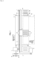
- FIG. 1 is a diagram illustrating an example of the image forming apparatus, which includes a serial liquid discharge device. The image forming apparatus is described with reference to FIGS. 1 and 2 .
- a carriage 3 is movably held by a main guide member 1 and a sub-guide member, that are bridged between left and right side plates.
- a main scanning motor 5 drives the carriage 3 to reciprocate in the main scanning direction (carriage moving direction) via a timing belt 8 looped around a drive pully 6 and a driven pully 7.
- the carriage 3 carries liquid discharging heads 4a and 4b (referred to as liquid discharging head 4 if distinction thereof is not necessary).
- the liquid discharging head 4 discharges color ink droplets of, for example, yellow (Y), cyan (C), magenta (M), and black (K).
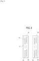
- the liquid discharging head 4 carries nozzle arrays Na and Nb each having multiple nozzles 4n disposed along the sub-scanning direction vertical to the main scanning direction with the ink discharging surface downward.
- the inkjet recording head 4 has two nozzle arrays Na and Nb, each including multiple nozzles 4n.
- liquid discharging head constituting the liquid discharging head 4 for example, it is possible to use a piezoelectric actuator such as a piezoelectric element and a thermal actuator that utilizes the phase change caused by film boiling of liquid by using an electric heat conversion element such as a heat element.
- a piezoelectric actuator such as a piezoelectric element
- a thermal actuator that utilizes the phase change caused by film boiling of liquid by using an electric heat conversion element such as a heat element.
- the liquid discharging head has a conveyor belt 12 serving as a conveying device to convey the sheet 10 at the position facing the inkjet discharging head 4 by electrostatic adsorption.
- the conveyor belt 12 takes an endless form, looped around a conveyor roller 13 and a tension roller 14.
- the conveyor belt 12 is moved around in the sub-scanning direction by the conveyor roller 13 rotationally driven by the sub-scanning motor 16 via a timing belt 17 and a timing pully 18.
- This conveyor belt 12 is charged (electric charges are applied) by a charging roller while moving around.
- a maintenance and recovery mechanism (cleaning unit) 20 configured to maintain and recover the liquid discharging head 4 is disposed beside the conveyor belt 12.
- a dummy discharging receiver 21 configured to receive dummy discharging from the liquid discharging head 4 is disposed beside the conveyor belt 12.
- the maintenance and recovery mechanism 20 includes, for example, a capping member 20a to cap a nozzle surface (on which the nozzle is formed) 41 ( FIG. 2 ) of the liquid discharging head 4, a wiping mechanism 20b to wipe the nozzle surface 41, and the dummy discharging receiver 21 to receive droplets not used to form an image.
- an encoder scale 23 forming a particular pattern is tensioned between both side plates along the main-scanning direction of the carriage 3, and the carriage 3 has an encoder sensor 24 including a transmission photosensor that reads the pattern of the encoder scale 23.
- These encoder scale 23 and the encoder sensor 24 constitute a linear encoder (main scanning encoder) to detect the movement of the carriage 3.
- a cord wheel 25 is mounted onto the shaft of the conveyor roller 13, and an encoder sensor 26 having a transmissive photosensor to detect a pattern formed on the cord wheel 25 is provided.
- These cord wheel 25 and the encoder sensor 26 constitute a rotary encoder (sub-scanning encoder) to detect the moving and the position of the conveyor belt 12.
- the sheet 10 is fed from a sheet feeder tray, adsorbed to the conveyor belt 12, and conveyed along the sub-scanning direction in accordance with the rotation of the conveyor belt 12.
- ink droplets are discharged onto the sheet 10 standing still to record an image in an amount of one line. After the sheet 10 is conveyed in a predetermined amount, the next line is recorded.
- the recording operation On receiving a signal indicating that the recording is finished or the rear end of the sheet 10 has reached the image recording area, the recording operation stops, and the sheet 10 is ejected to an ejection tray.
- the carriage 3 is moved in the printing (recording) standby mode to the maintenance and recovery mechanism 20 to clean the ink discharging head 4 by the maintenance and recovery mechanism 20.
- the liquid discharging head 4 may not be moved and the maintenance and recovery mechanism 20 may move to clean the liquid discharging head 4.
- the inkjet recording head 4 illustrated in FIG. 1 has two nozzle arrays Na and Nb, each including multiple nozzles 4n.
- the nozzle array Na of the liquid discharging head 4a discharges black (K) droplets and the other nozzle array Nb discharges cyan (C) droplets.
- the nozzle array Na of the liquid discharging head 4b discharges magenta (M) droplets and the other nozzle array Nb discharges yellow (Y) droplets.
- the wiping mechanism 20b that wipes the nozzle surface includes a wiping member 320 having a sheet-like form, a roller 410 to deliver the wiping member 320, a pressing roller 400 to press the delivered wiping member 320 against the nozzle surface, and a wind-up roller 420 to retrieve the wiping member 320 used for wiping.
- the wiping mechanism 20b may furthermore optionally include a rubber blade, etc., to wipe the nozzle surface other than the wiping member 320.
- the pressing force of the pressing roller 400 can be adjusted by adjusting the distance between the cleaning unit and the nozzle surface 41 by a spring.
- the pressing roller 400 is not limited to a roller but can be a fixed member made of resin or rubber.
- a mechanism of bringing the rubber blade, etc., into contact with the wiping member 320 having a sheet-like form is provided to impart a cleaning ability of the rubber blade, etc., to the wiping member 320 having a sheet-like form.
- the cleaning unit and the liquid discharging head 4 are relatively moved against each other while the wiping member 320 is being pressed against the nozzle surface, thereby wiping foreign matter 500 adhering to the nozzle surface.
- the foreign matter 500 adhering to the nozzle surface include, but are not limited to, mist ink produced during discharging of the ink from the nozzles, ink adhering to the nozzle surface when the ink is sucked from the nozzles during, for example, cleaning, adhesion ink which is dried mist ink or dried ink adhering to the cap member on the nozzle surface, and paper dust produced from printed matter.
- the wiping member 320 may be permeated with the cleaning liquid in advance.
- the ink is assumed to be dried and adhere to the nozzle surface after long standby period of time, etc., it is desirable to wipe the nozzle surface multiple times with the wiping member having a sheet-like form filled with the cleaning liquid and remove the foreign matter 500.
- the wiping member of the present disclosure includes a first layer to be brought into contact with the nozzle surface and one or more other layers. Also, the following relation is satisfied: t1 ⁇ t2, where t1 represents the thickness of the first layer and t2 represents the thickness of the one or more other layers and the porosity of the first layer is smaller than the porosity of at least one of the one or more other layers.
- FIG. 4 is a schematic diagram illustrating an example of a cross section of the wiping member 320 of the present disclosure.
- the wiping member 320 having a sheet-like form illustrated in FIG. 4 is made of a non-woven fabric and has a two-layer structure of a first layer 610, which is brought into contact with the nozzle surface, and a second layer 620.
- the wiping member 320 may employ a three-or-more-layer structure and include a farthermost layer which is disposed farthermost from the first layer and contacts the nozzle surface like the first layer to remove the foreign matter 500. That is, both sides of the wiping member 320 can be used to remove the foreign matter 500.
- the wiping member 320 may take another three-layer structure lined with a film to prevent strike through of the ink and reinforce the strength of the wiping material or a multilayer structure having multiple absorbing layers having different absorption, which are provided as the second layer or thereafter.
- Examples of materials constituting the wiping member 320 may include woven fabric, knitted fabric, and porous materials in addition to non-woven fabric.
- Non-woven fabric is preferable as the first layer because the non-woven fabric is relatively easy to control the thickness and the porosity thereof.
- Materials of fibers, such as non-woven fabric, woven fabric, and knitted fabric include, but are not limited to, cotton, hemp, silk, pulp, nylon, vinylon, polyester, polypropylene, polyethylene, rayon, cupra, acrylic, and polylactic acid.
- Non-woven fabric may be made not only of one type of fiber but also be of mixed plural types of fibers.
- Examples of the porous body include, but are not limited to, polyurethane, polyolefin, and PVA.
- methods of manufacturing non-woven fabric include, but are not limited to, wet type, dry type, spun bonding, melt blown, and flash spinning to form webs, and spun lacing, thermal bonding, chemical bonding, and needle punching to bond the webs.
- the "true density” is the true density of the fiber forming the sheet, and "apparent density” can be obtained by dividing the basis weight of the sheet-shaped material by thickness [basis weight/thickness].
- the wiping member to wipe off the adhesion ink has a high scraping power but cannot hold liquid components of, such as the ink and the cleaning liquid.
- a single-layer wiping member has insufficient cleaning ability. Therefore, the wiping member of the present disclosure has a portion capable of holding the liquid component other than the first layer while keeping the relation mentioned above between the layers.
- the porosity of the first layer is from 0.60 to 0.85 and preferably from 0.75 to 0.80.
- the porosity of the first layer is from 0.60 to 0.85, the ability of wiping off the adhesion ink can be improved, preventing the wiping member from becoming filmy and ameliorating liquid permeability.
- the porosity of at least one of the one or more layers is preferably from 0.80 to 0.99.
- the porosity of the layer other than the first layer is within the above range, the liquid absorbency can be improved.
- the wiping member can strike a balance between scraping ability and liquid absorption, thereby improving wiping ability.
- the thickness of the wiping member is preferably from 0.1 to 3 mm and more preferably from 0.2 to 0.7 mm. Since the thickness of the wiping member is 0.1 mm or more, a saturated water absorption amount of the liquid per area of the wiping member is sufficient, and the target ink can be sufficiently absorbed. Further, since the thickness of the wiping member is 3 mm or less, the liquid component of the ink can be still transferred from the first layer to the layer other than the first layer without degrading the absorption power of the layer other than the first layer. Therefore, the apparatus can be down-sized.
- At least the first layer of the wiping member is desirably made of non-woven fabric.
- non-woven fabric When non-woven fabric is used, a desirable numerical range of the thickness and a desirable numerical range of the porosity can be easily set.
- the one or more other layers include at least two layers and the following relations are satisfied: t1 ⁇ t4; and t3 ⁇ t4, where t3 represents the thickness of the farthermost layer of the one or more other layers located farthermost from the first layer, t4 represents the total thickness of the one or more other layers excluding the farthermost layer, and the porosity of the first layer and the porosity of the farthermost layer are smaller than the porosity of at least one of the one or more other layers excluding the farthermost layer, it is possible to wipe off the adhesion ink with good wiping property using both sides of the wiping member.
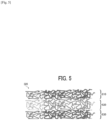
- FIG. 5 is a schematic diagram illustrating an example of a cross section of the wiping member 320 having the farthermost layer.
- the wiping member 320 having a sheet-like form illustrated in FIG. 5 is made of non-woven fabric and has a three-layered structure consisting of a first layer 610, a second layer 620, and a farthermost layer 630 located at a position farthermost from the first layer 610, from the side in contact with the nozzle surface. Like the first layer 610, the farthermost layer 630 is brought into contact with the nozzle surface to wipe off the adhesion ink.
- the thickness t1 of the first layer 610 and the thickness t3 of the farthermost layer 630 are thinner than the thickness of the second layer 620, and the porosity of the first layer 610 and the porosity of the farthermost layer 630 are smaller than the porosity of the second layer 620.
- the first layer 610 and the farthermost layer 630 may be identical. Alternatively, the farthermost layer 630 may have a different configuration from the first layer 610 if the farthermost layer 630 is thinner than the second layer 620 and the porosity of the farthermost layer 630 is lower than that of the second layer 620.
- FIG. 5 is a diagram illustrating a three-layer structure.
- a multilayer structure of four or more layers having multiple absorbing layers having different absorption are provided between the second layer 620 and the farthermost layer 630 may be used.
- the nozzle surface can be wiped by using both surfaces of the wiping member.
- the wiping member 320 having a sheet-like form may be rolled up and the roll may be changed to invert the front and back surfaces, or a reversing mechanism may be used. Therefore, both surfaces of the wiping member 320 can be used.
- the porosity of the farthermost layer 630 can also be calculated by the relation 1 mentioned above.
- Each of the thickness of the first layer and the thickness of the farthermost layer is desirably thinner than the total thickness of the first layer and the one or more other layers excluding the farthermost layer.
- the porosity of the farthermost layer is preferably from 0.60 to 0.85 and more preferably from 0.75 to 0.80.
- the porosity of the farthermost layer is from 0.60 to 0.85, the ability of wiping off the adhesion ink can be improved, preventing the wiping member from becoming filmy and ameliorating liquid permeability.
- Non-woven fabric is desirably used because thickness and porosity are relatively easily controlled.
- Materials of fibers, such as non-woven fabric, woven fabric, and knitted fabric include, but are not limited to, cotton, hemp, silk, pulp, nylon, vinylon, polyester, polypropylene, polyethylene, rayon, cupra, acrylic, and polylactic acid.
- Non-woven fabric may be made not only of one type of fiber but also be of mixed plural types of fibers.
- the porous body include, but are not limited to, polyurethane, polyolefin, and PVA.
- methods of manufacturing non-woven fabric include, but are not limited to, wet type, dry type, spun bonding, melt blown, and flash spinning to form webs, and spun lacing, thermal bonding, chemical bonding, and needle punching to bond the webs.
- the wiping surface of the wiping member 320 has a surface roughness Rz of 170 ⁇ m or more obtained by surface roughness measurement by using, for example, a laser microscope.
- the surface roughness Rz of the wiping surface is 170 ⁇ m or more, the meniscus in the nozzle is not easily broken so that the nozzle surface can be wiped without causing discharging defects.
- Wiping members of Examples 1 to 30 and Comparative Examples 1 to 4 were prepared according to the formulation shown in Table 1 below.
- the wiping members were determined as practically usable when graded B or above, preferable when graded A or above, and more preferable when graded S according to the following evaluation criteria.
- the front and back surfaces of the wiping member were reversed, 20 ⁇ l/cm 2 of the above-described cleaning liquid was applied to the third layer shown in Table 1 and thereafter brought into contact with the nozzle surface followed by the same evaluation as for the first layer brought into contact with the nozzle surface.
- the adhesion ink can be wiped off by using both sides.
Landscapes
- Engineering & Computer Science (AREA)
- Textile Engineering (AREA)
- Chemical & Material Sciences (AREA)
- Chemical Kinetics & Catalysis (AREA)
- General Chemical & Material Sciences (AREA)
- Ink Jet (AREA)
Claims (11)
- Flüssigkeitsausstoßkopf-Wischelement (320), eine bahnartige Form aufweisend, um eine Düsenoberfläche eines Flüssigkeitsausstoßungkopfes abzuwischen, Folgendes umfassend:eine erste Schicht (610), die dafür konfiguriert ist, mit der Düsenoberfläche in Kontakt gebracht zu werden, undeine oder mehrere andere Schichten (620, 630),wobei das folgende Verhältnis erfüllt ist: t1 < t2, worin t1 eine Dicke der ersten Schicht (610) darstellt und t2 eine Dicke der einen oder der mehreren anderen Schichten (620, 630) darstellt,wobei eine Porosität der ersten Schicht (610) kleiner als eine Porosität mindestens einer der einen oder der mehreren anderen Schichten (620, 630) ist, und die Porosität der ersten Schicht (610) 0,60 bis 0,85 beträgt;dadurch gekennzeichnet, dassdie erste Schicht eine Oberflächenrauigkeit von 170 µm oder mehr aufweist, ermittelt durch eine Oberflächenrauigkeits-Messung unter Verwendung eines Lasermikroskops.
- Wischelement nach Anspruch 1, wobei die Porosität der ersten Schicht (610) 0,75 bis 0,80 beträgt.
- Wischelement nach Anspruch 1 oder 2, wobei die erste Schicht (610) aus Vliesstoff besteht.
- Wischelement nach einem der Ansprüche 1 bis 3, wobei die Porosität mindestens einer der einen oder der mehreren anderen Schichten 0,80 bis 0,99 beträgt.
- Wischelement nach einem der Ansprüche 1 bis 4, wobei das Wischelement (320) eine Dicke von 0,1 bis 3 mm aufweist.
- Wischelement nach Anspruch 5, wobei das Wischelement (320) eine Dicke von 0,2 bis 0,7 mm aufweist.
- Wischelement nach einem der Ansprüche 1 bis 6,wobei die eine oder die mehreren anderen Schichten (620, 630) mindestens zwei Schichten umfasst und die folgenden Verhältnisse erfüllt sind: t1 < t4, und t3 < t4, worin t3 eine Dicke einer entferntesten Schicht (630) der einen oder der mehreren anderen Schichten (620, 630) darstellt, die sich am weitesten von der ersten Schicht (610) entfernt befindet, t4 eine Gesamtdicke der einen oder der mehreren anderen Schichten (620), mit Ausnahme der entferntesten Schicht (630), darstellt,wobei die Porosität der ersten Schicht (610) und eine Porosität der entferntesten Schicht (630) kleiner als eine Porosität von mindestens einer der einen oder der mehreren anderen Schichten (620), mit Ausnahme der entferntesten Schicht, sind.
- Wischelement nach Anspruch 7, wobei die Porosität der entferntesten Schicht (630) 0,60 bis 0,85 beträgt.
- Wischelement nach Anspruch 8, wobei die Porosität der entferntesten Schicht (630) 0,75 bis 0,80 beträgt.
- Wischverfahren, Folgendes umfassend:relatives Bewegen eines Flüssigkeitsausstoßungkopfes (4) und eines Wischelements (320), das eine bahnartige Form aufweist, undAbwischen einer Düsenoberfläche des Flüssigkeitsausstoßungkopfes (4) durch das Wischelement (320),wobei das Wischelement (320) ein Flüssigkeitsausstoßkopf-Wischelement nach einem der vorhergehenden Ansprüche ist.
- Bildgebungsvorrichtung, Folgendes umfassend:einen Flüssigkeitsausstoßungkopf (4), der eine Düsenoberfläche umfasst; undein Wischelement (320) nach einem der Ansprüche 1 bis 9.
Applications Claiming Priority (3)
| Application Number | Priority Date | Filing Date | Title |
|---|---|---|---|
| JP2018049359 | 2018-03-16 | ||
| JP2018210538A JP7205172B2 (ja) | 2018-03-16 | 2018-11-08 | 払拭部材、払拭方法、および画像形成装置 |
| PCT/JP2019/008898 WO2019176691A1 (en) | 2018-03-16 | 2019-03-06 | Wiping member, wiping method, and image forming apparatus |
Publications (2)
| Publication Number | Publication Date |
|---|---|
| EP3765296A1 EP3765296A1 (de) | 2021-01-20 |
| EP3765296B1 true EP3765296B1 (de) | 2024-08-28 |
Family
ID=68064489
Family Applications (1)
| Application Number | Title | Priority Date | Filing Date |
|---|---|---|---|
| EP19713884.5A Active EP3765296B1 (de) | 2018-03-16 | 2019-03-06 | Wischelement, wischverfahren und bilderzeugungsvorrichtung |
Country Status (3)
| Country | Link |
|---|---|
| US (1) | US12030090B2 (de) |
| EP (1) | EP3765296B1 (de) |
| JP (1) | JP7205172B2 (de) |
Families Citing this family (7)
| Publication number | Priority date | Publication date | Assignee | Title |
|---|---|---|---|---|
| JP2020082589A (ja) | 2018-11-29 | 2020-06-04 | 株式会社リコー | インクジェット印刷装置、及びインクジェット印刷方法 |
| EP4031378B1 (de) * | 2019-09-18 | 2024-08-07 | Ricoh Company, Ltd. | Wischverfahren und bilderzeugungsvorrichtung |
| CN215744958U (zh) * | 2021-03-16 | 2022-02-08 | 三赢科技(深圳)有限公司 | 擦拭装置及机台设备 |
| JP2022176793A (ja) * | 2021-05-17 | 2022-11-30 | 株式会社リコー | 吐出装置、印刷方法、及び払拭部材 |
| JP7124948B1 (ja) | 2021-12-15 | 2022-08-24 | 株式会社リコー | 活性エネルギー線硬化型組成物、活性エネルギー線硬化型インク組成物、インクジェット用インク組成物、組成物収容容器、2次元又は3次元の像形成装置、2次元又は3次元の像形成方法、硬化物、加飾体、積層体、フレキシブルデバイス用部材、及びフレキシブルデバイス |
| EP4452651A1 (de) * | 2021-12-22 | 2024-10-30 | Baldwin Jimek AB | Reinigungsgewebe und zugehörige vorrichtung und verfahren |
| CN115805201B (zh) * | 2022-12-28 | 2025-09-23 | 苏州凌云光工业智能技术有限公司 | 擦拭装置 |
Citations (1)
| Publication number | Priority date | Publication date | Assignee | Title |
|---|---|---|---|---|
| US20170119226A1 (en) * | 2014-06-17 | 2017-05-04 | Kuraray Co., Ltd. | Water absorbent laminate and method for producing same |
Family Cites Families (17)
| Publication number | Priority date | Publication date | Assignee | Title |
|---|---|---|---|---|
| JP3033220B2 (ja) * | 1991-03-22 | 2000-04-17 | 東レ株式会社 | ワイピングクロス |
| JP3018642B2 (ja) | 1991-09-27 | 2000-03-13 | 富士通株式会社 | インク吸引キャップ |
| US6860658B2 (en) * | 2002-02-15 | 2005-03-01 | Brady Worldwide, Inc. | Ribbon wiper |
| JP4144556B2 (ja) * | 2004-04-22 | 2008-09-03 | ソニー株式会社 | 液体吐出ヘッドのクリーニング装置及び液体吐出装置 |
| US7384121B2 (en) | 2003-05-29 | 2008-06-10 | Sony Corporation | Cleaner of liquid discharger head and liquid discharger |
| JP2005313606A (ja) | 2004-03-30 | 2005-11-10 | Seiko Epson Corp | 液体噴射装置のワイパクリーニング装置 |
| US7234189B2 (en) * | 2005-07-19 | 2007-06-26 | Chi-Hung Chen | Cleaning implement |
| WO2007097249A1 (ja) | 2006-02-20 | 2007-08-30 | Daicel Chemical Industries, Ltd. | 多孔性フィルム及び多孔性フィルムを用いた積層体 |
| JP4940917B2 (ja) * | 2006-12-01 | 2012-05-30 | 富士ゼロックス株式会社 | 液滴吐出装置 |
| JP5966541B2 (ja) | 2012-04-10 | 2016-08-10 | セイコーエプソン株式会社 | 液体噴射装置 |
| JP2014000704A (ja) | 2012-06-18 | 2014-01-09 | Ricoh Co Ltd | 液滴吐出ヘッドのクリーニング装置、クリーニング方法および液滴吐出装置 |
| JP6263844B2 (ja) * | 2013-03-01 | 2018-01-24 | セイコーエプソン株式会社 | インクジェット記録装置 |
| JP2014188900A (ja) | 2013-03-27 | 2014-10-06 | Seiko Epson Corp | ワイパー装置及び液体噴射装置 |
| WO2016047193A1 (ja) * | 2014-09-25 | 2016-03-31 | 富士フイルム株式会社 | 払拭機構、液滴吐出装置および払拭方法 |
| CN205856783U (zh) | 2016-05-27 | 2017-01-04 | 江阴健发特种纺织品有限公司 | 用于擦拭的无纺布 |
| CN205767862U (zh) | 2016-05-27 | 2016-12-07 | 江阴健发特种纺织品有限公司 | 擦拭用复合无纺布 |
| JP6146524B1 (ja) * | 2016-09-21 | 2017-06-14 | 富士ゼロックス株式会社 | 払拭装置、吐出装置 |
-
2018
- 2018-11-08 JP JP2018210538A patent/JP7205172B2/ja active Active
-
2019
- 2019-03-06 EP EP19713884.5A patent/EP3765296B1/de active Active
- 2019-03-06 US US16/981,175 patent/US12030090B2/en active Active
Patent Citations (1)
| Publication number | Priority date | Publication date | Assignee | Title |
|---|---|---|---|---|
| US20170119226A1 (en) * | 2014-06-17 | 2017-05-04 | Kuraray Co., Ltd. | Water absorbent laminate and method for producing same |
Also Published As
| Publication number | Publication date |
|---|---|
| US20210016327A1 (en) | 2021-01-21 |
| JP2019162850A (ja) | 2019-09-26 |
| JP7205172B2 (ja) | 2023-01-17 |
| EP3765296A1 (de) | 2021-01-20 |
| US12030090B2 (en) | 2024-07-09 |
Similar Documents
| Publication | Publication Date | Title |
|---|---|---|
| EP3765296B1 (de) | Wischelement, wischverfahren und bilderzeugungsvorrichtung | |
| EP3539782B1 (de) | Flüssigkeitsausgabevorrichtung und reinigungsverfahren | |
| JP4940917B2 (ja) | 液滴吐出装置 | |
| EP3530466B1 (de) | Wischvorrichtung, kopfpflegevorrichtung und flüssigkeitsausstossvorrichtung | |
| CN103287097B (zh) | 液体喷射设备、用于液体喷射头的清洗设备和喷墨记录设备 | |
| JP7010047B2 (ja) | ヘッド清掃装置および液体を吐出する装置 | |
| US10889119B2 (en) | Wiping device, wiping member, liquid discharging device, and wiping method | |
| JP5353530B2 (ja) | 画像形成装置 | |
| JP7031363B2 (ja) | 液体吐出装置用払拭部材、液体吐出ヘッドの払拭装置、液体吐出ヘッドの払拭方法、及び液体吐出装置 | |
| WO2019176691A1 (en) | Wiping member, wiping method, and image forming apparatus | |
| JP5919744B2 (ja) | インクジェット記録装置 | |
| JP7020174B2 (ja) | 液体吐出装置用払拭部材、液体吐出ヘッドの払拭装置、液体吐出ヘッドの払拭方法、及び液体吐出装置 | |
| JP2004161454A (ja) | インクジェット記録装置 | |
| JP7413783B2 (ja) | 液体吐出ヘッドの払拭装置、液体吐出ヘッドの払拭方法、液体吐出ヘッドの払拭ユニット、及び液体吐出装置 | |
| US11981141B2 (en) | Wiping method and image forming apparatus | |
| JP2024001474A (ja) | ヘッドメンテナンス装置、液体を吐出する装置及びヘッドメンテナンス方法 | |
| JP2022181621A (ja) | 液体吐出ヘッドの払拭装置、液体吐出ヘッドの払拭方法、及び液体吐出装置 | |
| HK40104488A (zh) | 数字印刷系统中喷墨喷嘴的清洁 | |
| JPH08244243A (ja) | インクジェット記録装置 |
Legal Events
| Date | Code | Title | Description |
|---|---|---|---|
| STAA | Information on the status of an ep patent application or granted ep patent |
Free format text: STATUS: UNKNOWN |
|
| STAA | Information on the status of an ep patent application or granted ep patent |
Free format text: STATUS: THE INTERNATIONAL PUBLICATION HAS BEEN MADE |
|
| PUAI | Public reference made under article 153(3) epc to a published international application that has entered the european phase |
Free format text: ORIGINAL CODE: 0009012 |
|
| STAA | Information on the status of an ep patent application or granted ep patent |
Free format text: STATUS: REQUEST FOR EXAMINATION WAS MADE |
|
| 17P | Request for examination filed |
Effective date: 20200910 |
|
| AK | Designated contracting states |
Kind code of ref document: A1 Designated state(s): AL AT BE BG CH CY CZ DE DK EE ES FI FR GB GR HR HU IE IS IT LI LT LU LV MC MK MT NL NO PL PT RO RS SE SI SK SM TR |
|
| AX | Request for extension of the european patent |
Extension state: BA ME |
|
| DAV | Request for validation of the european patent (deleted) | ||
| DAX | Request for extension of the european patent (deleted) | ||
| STAA | Information on the status of an ep patent application or granted ep patent |
Free format text: STATUS: EXAMINATION IS IN PROGRESS |
|
| 17Q | First examination report despatched |
Effective date: 20221007 |
|
| GRAP | Despatch of communication of intention to grant a patent |
Free format text: ORIGINAL CODE: EPIDOSNIGR1 |
|
| STAA | Information on the status of an ep patent application or granted ep patent |
Free format text: STATUS: GRANT OF PATENT IS INTENDED |
|
| GRAJ | Information related to disapproval of communication of intention to grant by the applicant or resumption of examination proceedings by the epo deleted |
Free format text: ORIGINAL CODE: EPIDOSDIGR1 |
|
| STAA | Information on the status of an ep patent application or granted ep patent |
Free format text: STATUS: EXAMINATION IS IN PROGRESS |
|
| INTG | Intention to grant announced |
Effective date: 20240214 |
|
| GRAP | Despatch of communication of intention to grant a patent |
Free format text: ORIGINAL CODE: EPIDOSNIGR1 |
|
| STAA | Information on the status of an ep patent application or granted ep patent |
Free format text: STATUS: GRANT OF PATENT IS INTENDED |
|
| INTC | Intention to grant announced (deleted) | ||
| INTG | Intention to grant announced |
Effective date: 20240326 |
|
| P01 | Opt-out of the competence of the unified patent court (upc) registered |
Effective date: 20240412 |
|
| GRAS | Grant fee paid |
Free format text: ORIGINAL CODE: EPIDOSNIGR3 |
|
| GRAA | (expected) grant |
Free format text: ORIGINAL CODE: 0009210 |
|
| STAA | Information on the status of an ep patent application or granted ep patent |
Free format text: STATUS: THE PATENT HAS BEEN GRANTED |
|
| AK | Designated contracting states |
Kind code of ref document: B1 Designated state(s): AL AT BE BG CH CY CZ DE DK EE ES FI FR GB GR HR HU IE IS IT LI LT LU LV MC MK MT NL NO PL PT RO RS SE SI SK SM TR |
|
| REG | Reference to a national code |
Ref country code: GB Ref legal event code: FG4D |
|
| REG | Reference to a national code |
Ref country code: CH Ref legal event code: EP |
|
| REG | Reference to a national code |
Ref country code: DE Ref legal event code: R096 Ref document number: 602019057836 Country of ref document: DE |
|
| REG | Reference to a national code |
Ref country code: IE Ref legal event code: FG4D |
|
| REG | Reference to a national code |
Ref country code: LT Ref legal event code: MG9D |
|
| PG25 | Lapsed in a contracting state [announced via postgrant information from national office to epo] |
Ref country code: NO Free format text: LAPSE BECAUSE OF FAILURE TO SUBMIT A TRANSLATION OF THE DESCRIPTION OR TO PAY THE FEE WITHIN THE PRESCRIBED TIME-LIMIT Effective date: 20241128 |
|
| REG | Reference to a national code |
Ref country code: AT Ref legal event code: MK05 Ref document number: 1717559 Country of ref document: AT Kind code of ref document: T Effective date: 20240828 |
|
| PG25 | Lapsed in a contracting state [announced via postgrant information from national office to epo] |
Ref country code: NL Free format text: LAPSE BECAUSE OF FAILURE TO SUBMIT A TRANSLATION OF THE DESCRIPTION OR TO PAY THE FEE WITHIN THE PRESCRIBED TIME-LIMIT Effective date: 20240828 Ref country code: GR Free format text: LAPSE BECAUSE OF FAILURE TO SUBMIT A TRANSLATION OF THE DESCRIPTION OR TO PAY THE FEE WITHIN THE PRESCRIBED TIME-LIMIT Effective date: 20241129 Ref country code: PL Free format text: LAPSE BECAUSE OF FAILURE TO SUBMIT A TRANSLATION OF THE DESCRIPTION OR TO PAY THE FEE WITHIN THE PRESCRIBED TIME-LIMIT Effective date: 20240828 Ref country code: PT Free format text: LAPSE BECAUSE OF FAILURE TO SUBMIT A TRANSLATION OF THE DESCRIPTION OR TO PAY THE FEE WITHIN THE PRESCRIBED TIME-LIMIT Effective date: 20241230 Ref country code: FI Free format text: LAPSE BECAUSE OF FAILURE TO SUBMIT A TRANSLATION OF THE DESCRIPTION OR TO PAY THE FEE WITHIN THE PRESCRIBED TIME-LIMIT Effective date: 20240828 |
|
| PG25 | Lapsed in a contracting state [announced via postgrant information from national office to epo] |
Ref country code: BG Free format text: LAPSE BECAUSE OF FAILURE TO SUBMIT A TRANSLATION OF THE DESCRIPTION OR TO PAY THE FEE WITHIN THE PRESCRIBED TIME-LIMIT Effective date: 20240828 |
|
| PG25 | Lapsed in a contracting state [announced via postgrant information from national office to epo] |
Ref country code: LV Free format text: LAPSE BECAUSE OF FAILURE TO SUBMIT A TRANSLATION OF THE DESCRIPTION OR TO PAY THE FEE WITHIN THE PRESCRIBED TIME-LIMIT Effective date: 20240828 |
|
| REG | Reference to a national code |
Ref country code: NL Ref legal event code: MP Effective date: 20240828 |
|
| PG25 | Lapsed in a contracting state [announced via postgrant information from national office to epo] |
Ref country code: IS Free format text: LAPSE BECAUSE OF FAILURE TO SUBMIT A TRANSLATION OF THE DESCRIPTION OR TO PAY THE FEE WITHIN THE PRESCRIBED TIME-LIMIT Effective date: 20241228 Ref country code: AT Free format text: LAPSE BECAUSE OF FAILURE TO SUBMIT A TRANSLATION OF THE DESCRIPTION OR TO PAY THE FEE WITHIN THE PRESCRIBED TIME-LIMIT Effective date: 20240828 |
|
| PG25 | Lapsed in a contracting state [announced via postgrant information from national office to epo] |
Ref country code: HR Free format text: LAPSE BECAUSE OF FAILURE TO SUBMIT A TRANSLATION OF THE DESCRIPTION OR TO PAY THE FEE WITHIN THE PRESCRIBED TIME-LIMIT Effective date: 20240828 |
|
| PG25 | Lapsed in a contracting state [announced via postgrant information from national office to epo] |
Ref country code: ES Free format text: LAPSE BECAUSE OF FAILURE TO SUBMIT A TRANSLATION OF THE DESCRIPTION OR TO PAY THE FEE WITHIN THE PRESCRIBED TIME-LIMIT Effective date: 20240828 Ref country code: RS Free format text: LAPSE BECAUSE OF FAILURE TO SUBMIT A TRANSLATION OF THE DESCRIPTION OR TO PAY THE FEE WITHIN THE PRESCRIBED TIME-LIMIT Effective date: 20241128 |
|
| PG25 | Lapsed in a contracting state [announced via postgrant information from national office to epo] |
Ref country code: RS Free format text: LAPSE BECAUSE OF FAILURE TO SUBMIT A TRANSLATION OF THE DESCRIPTION OR TO PAY THE FEE WITHIN THE PRESCRIBED TIME-LIMIT Effective date: 20241128 Ref country code: PT Free format text: LAPSE BECAUSE OF FAILURE TO SUBMIT A TRANSLATION OF THE DESCRIPTION OR TO PAY THE FEE WITHIN THE PRESCRIBED TIME-LIMIT Effective date: 20241230 Ref country code: PL Free format text: LAPSE BECAUSE OF FAILURE TO SUBMIT A TRANSLATION OF THE DESCRIPTION OR TO PAY THE FEE WITHIN THE PRESCRIBED TIME-LIMIT Effective date: 20240828 Ref country code: NO Free format text: LAPSE BECAUSE OF FAILURE TO SUBMIT A TRANSLATION OF THE DESCRIPTION OR TO PAY THE FEE WITHIN THE PRESCRIBED TIME-LIMIT Effective date: 20241128 Ref country code: NL Free format text: LAPSE BECAUSE OF FAILURE TO SUBMIT A TRANSLATION OF THE DESCRIPTION OR TO PAY THE FEE WITHIN THE PRESCRIBED TIME-LIMIT Effective date: 20240828 Ref country code: LV Free format text: LAPSE BECAUSE OF FAILURE TO SUBMIT A TRANSLATION OF THE DESCRIPTION OR TO PAY THE FEE WITHIN THE PRESCRIBED TIME-LIMIT Effective date: 20240828 Ref country code: IS Free format text: LAPSE BECAUSE OF FAILURE TO SUBMIT A TRANSLATION OF THE DESCRIPTION OR TO PAY THE FEE WITHIN THE PRESCRIBED TIME-LIMIT Effective date: 20241228 Ref country code: HR Free format text: LAPSE BECAUSE OF FAILURE TO SUBMIT A TRANSLATION OF THE DESCRIPTION OR TO PAY THE FEE WITHIN THE PRESCRIBED TIME-LIMIT Effective date: 20240828 Ref country code: GR Free format text: LAPSE BECAUSE OF FAILURE TO SUBMIT A TRANSLATION OF THE DESCRIPTION OR TO PAY THE FEE WITHIN THE PRESCRIBED TIME-LIMIT Effective date: 20241129 Ref country code: FI Free format text: LAPSE BECAUSE OF FAILURE TO SUBMIT A TRANSLATION OF THE DESCRIPTION OR TO PAY THE FEE WITHIN THE PRESCRIBED TIME-LIMIT Effective date: 20240828 Ref country code: ES Free format text: LAPSE BECAUSE OF FAILURE TO SUBMIT A TRANSLATION OF THE DESCRIPTION OR TO PAY THE FEE WITHIN THE PRESCRIBED TIME-LIMIT Effective date: 20240828 Ref country code: BG Free format text: LAPSE BECAUSE OF FAILURE TO SUBMIT A TRANSLATION OF THE DESCRIPTION OR TO PAY THE FEE WITHIN THE PRESCRIBED TIME-LIMIT Effective date: 20240828 Ref country code: AT Free format text: LAPSE BECAUSE OF FAILURE TO SUBMIT A TRANSLATION OF THE DESCRIPTION OR TO PAY THE FEE WITHIN THE PRESCRIBED TIME-LIMIT Effective date: 20240828 |
|
| PG25 | Lapsed in a contracting state [announced via postgrant information from national office to epo] |
Ref country code: DK Free format text: LAPSE BECAUSE OF FAILURE TO SUBMIT A TRANSLATION OF THE DESCRIPTION OR TO PAY THE FEE WITHIN THE PRESCRIBED TIME-LIMIT Effective date: 20240828 Ref country code: SM Free format text: LAPSE BECAUSE OF FAILURE TO SUBMIT A TRANSLATION OF THE DESCRIPTION OR TO PAY THE FEE WITHIN THE PRESCRIBED TIME-LIMIT Effective date: 20240828 Ref country code: RO Free format text: LAPSE BECAUSE OF FAILURE TO SUBMIT A TRANSLATION OF THE DESCRIPTION OR TO PAY THE FEE WITHIN THE PRESCRIBED TIME-LIMIT Effective date: 20240828 |
|
| PG25 | Lapsed in a contracting state [announced via postgrant information from national office to epo] |
Ref country code: EE Free format text: LAPSE BECAUSE OF FAILURE TO SUBMIT A TRANSLATION OF THE DESCRIPTION OR TO PAY THE FEE WITHIN THE PRESCRIBED TIME-LIMIT Effective date: 20240828 |
|
| PG25 | Lapsed in a contracting state [announced via postgrant information from national office to epo] |
Ref country code: CZ Free format text: LAPSE BECAUSE OF FAILURE TO SUBMIT A TRANSLATION OF THE DESCRIPTION OR TO PAY THE FEE WITHIN THE PRESCRIBED TIME-LIMIT Effective date: 20240828 |
|
| PG25 | Lapsed in a contracting state [announced via postgrant information from national office to epo] |
Ref country code: IT Free format text: LAPSE BECAUSE OF FAILURE TO SUBMIT A TRANSLATION OF THE DESCRIPTION OR TO PAY THE FEE WITHIN THE PRESCRIBED TIME-LIMIT Effective date: 20240828 Ref country code: SK Free format text: LAPSE BECAUSE OF FAILURE TO SUBMIT A TRANSLATION OF THE DESCRIPTION OR TO PAY THE FEE WITHIN THE PRESCRIBED TIME-LIMIT Effective date: 20240828 |
|
| REG | Reference to a national code |
Ref country code: DE Ref legal event code: R097 Ref document number: 602019057836 Country of ref document: DE |
|
| PLBE | No opposition filed within time limit |
Free format text: ORIGINAL CODE: 0009261 |
|
| STAA | Information on the status of an ep patent application or granted ep patent |
Free format text: STATUS: NO OPPOSITION FILED WITHIN TIME LIMIT |
|
| 26N | No opposition filed |
Effective date: 20250530 |
|
| PG25 | Lapsed in a contracting state [announced via postgrant information from national office to epo] |
Ref country code: SE Free format text: LAPSE BECAUSE OF FAILURE TO SUBMIT A TRANSLATION OF THE DESCRIPTION OR TO PAY THE FEE WITHIN THE PRESCRIBED TIME-LIMIT Effective date: 20240828 |
|
| PG25 | Lapsed in a contracting state [announced via postgrant information from national office to epo] |
Ref country code: MC Free format text: LAPSE BECAUSE OF FAILURE TO SUBMIT A TRANSLATION OF THE DESCRIPTION OR TO PAY THE FEE WITHIN THE PRESCRIBED TIME-LIMIT Effective date: 20240828 |
|
| REG | Reference to a national code |
Ref country code: CH Ref legal event code: H13 Free format text: ST27 STATUS EVENT CODE: U-0-0-H10-H13 (AS PROVIDED BY THE NATIONAL OFFICE) Effective date: 20251023 |
|
| PG25 | Lapsed in a contracting state [announced via postgrant information from national office to epo] |
Ref country code: LU Free format text: LAPSE BECAUSE OF NON-PAYMENT OF DUE FEES Effective date: 20250306 |
|
| REG | Reference to a national code |
Ref country code: BE Ref legal event code: MM Effective date: 20250331 |
|
| PG25 | Lapsed in a contracting state [announced via postgrant information from national office to epo] |
Ref country code: BE Free format text: LAPSE BECAUSE OF NON-PAYMENT OF DUE FEES Effective date: 20250331 |
|
| PG25 | Lapsed in a contracting state [announced via postgrant information from national office to epo] |
Ref country code: CH Free format text: LAPSE BECAUSE OF NON-PAYMENT OF DUE FEES Effective date: 20250331 |
|
| PG25 | Lapsed in a contracting state [announced via postgrant information from national office to epo] |
Ref country code: IE Free format text: LAPSE BECAUSE OF NON-PAYMENT OF DUE FEES Effective date: 20250306 |
|
| PGFP | Annual fee paid to national office [announced via postgrant information from national office to epo] |
Ref country code: GB Payment date: 20260324 Year of fee payment: 8 |
|
| PGFP | Annual fee paid to national office [announced via postgrant information from national office to epo] |
Ref country code: DE Payment date: 20260319 Year of fee payment: 8 |
|
| PGFP | Annual fee paid to national office [announced via postgrant information from national office to epo] |
Ref country code: FR Payment date: 20260323 Year of fee payment: 8 |