EP3764085A2 - Fluoreszenz-scanner mit komplettobjektträger - Google Patents
Fluoreszenz-scanner mit komplettobjektträger Download PDFInfo
- Publication number
- EP3764085A2 EP3764085A2 EP20172920.9A EP20172920A EP3764085A2 EP 3764085 A2 EP3764085 A2 EP 3764085A2 EP 20172920 A EP20172920 A EP 20172920A EP 3764085 A2 EP3764085 A2 EP 3764085A2
- Authority
- EP
- European Patent Office
- Prior art keywords
- image data
- objective lens
- sample
- fluorescence
- image
- Prior art date
- Legal status (The legal status is an assumption and is not a legal conclusion. Google has not performed a legal analysis and makes no representation as to the accuracy of the status listed.)
- Withdrawn
Links
- 238000000034 method Methods 0.000 claims abstract description 73
- 238000005286 illumination Methods 0.000 claims abstract description 61
- 238000012935 Averaging Methods 0.000 claims abstract description 8
- 230000005284 excitation Effects 0.000 claims description 37
- 238000003491 array Methods 0.000 claims description 17
- 238000003705 background correction Methods 0.000 claims description 17
- 230000033001 locomotion Effects 0.000 claims description 16
- 230000003287 optical effect Effects 0.000 claims description 9
- 238000010408 sweeping Methods 0.000 claims description 9
- 230000010354 integration Effects 0.000 claims description 8
- 238000012937 correction Methods 0.000 claims description 4
- 238000013507 mapping Methods 0.000 claims description 2
- 230000007170 pathology Effects 0.000 abstract description 5
- 238000000339 bright-field microscopy Methods 0.000 abstract description 2
- 230000008569 process Effects 0.000 description 39
- 238000013500 data storage Methods 0.000 description 32
- 238000010586 diagram Methods 0.000 description 16
- 238000004458 analytical method Methods 0.000 description 13
- 230000008901 benefit Effects 0.000 description 11
- 238000003384 imaging method Methods 0.000 description 11
- BFMYDTVEBKDAKJ-UHFFFAOYSA-L disodium;(2',7'-dibromo-3',6'-dioxido-3-oxospiro[2-benzofuran-1,9'-xanthene]-4'-yl)mercury;hydrate Chemical compound O.[Na+].[Na+].O1C(=O)C2=CC=CC=C2C21C1=CC(Br)=C([O-])C([Hg])=C1OC1=C2C=C(Br)C([O-])=C1 BFMYDTVEBKDAKJ-UHFFFAOYSA-L 0.000 description 9
- 238000009826 distribution Methods 0.000 description 9
- 238000012800 visualization Methods 0.000 description 9
- 229920006395 saturated elastomer Polymers 0.000 description 8
- 238000013523 data management Methods 0.000 description 7
- 238000003860 storage Methods 0.000 description 7
- 230000002123 temporal effect Effects 0.000 description 7
- 238000007493 shaping process Methods 0.000 description 6
- 238000004891 communication Methods 0.000 description 5
- 230000006870 function Effects 0.000 description 5
- 238000004445 quantitative analysis Methods 0.000 description 5
- 230000000875 corresponding effect Effects 0.000 description 4
- 238000000799 fluorescence microscopy Methods 0.000 description 4
- 241000276498 Pollachius virens Species 0.000 description 3
- 239000000975 dye Substances 0.000 description 3
- 239000007788 liquid Substances 0.000 description 3
- 230000002085 persistent effect Effects 0.000 description 3
- 230000035945 sensitivity Effects 0.000 description 3
- 238000013481 data capture Methods 0.000 description 2
- 230000001419 dependent effect Effects 0.000 description 2
- 238000013461 design Methods 0.000 description 2
- 239000000463 material Substances 0.000 description 2
- QSHDDOUJBYECFT-UHFFFAOYSA-N mercury Chemical compound [Hg] QSHDDOUJBYECFT-UHFFFAOYSA-N 0.000 description 2
- 229910052753 mercury Inorganic materials 0.000 description 2
- 238000005424 photoluminescence Methods 0.000 description 2
- 230000001360 synchronised effect Effects 0.000 description 2
- 238000013519 translation Methods 0.000 description 2
- 230000004075 alteration Effects 0.000 description 1
- 230000008512 biological response Effects 0.000 description 1
- 230000005540 biological transmission Effects 0.000 description 1
- 230000015572 biosynthetic process Effects 0.000 description 1
- 230000001413 cellular effect Effects 0.000 description 1
- 239000003086 colorant Substances 0.000 description 1
- 238000004040 coloring Methods 0.000 description 1
- 239000002131 composite material Substances 0.000 description 1
- 230000006835 compression Effects 0.000 description 1
- 238000007906 compression Methods 0.000 description 1
- 230000001276 controlling effect Effects 0.000 description 1
- 238000007796 conventional method Methods 0.000 description 1
- 230000002596 correlated effect Effects 0.000 description 1
- 238000007405 data analysis Methods 0.000 description 1
- 238000013079 data visualisation Methods 0.000 description 1
- 230000003670 easy-to-clean Effects 0.000 description 1
- 239000000835 fiber Substances 0.000 description 1
- 238000001914 filtration Methods 0.000 description 1
- 238000002073 fluorescence micrograph Methods 0.000 description 1
- 230000006872 improvement Effects 0.000 description 1
- 230000002452 interceptive effect Effects 0.000 description 1
- 238000012417 linear regression Methods 0.000 description 1
- 238000007726 management method Methods 0.000 description 1
- 230000000873 masking effect Effects 0.000 description 1
- 229910001507 metal halide Inorganic materials 0.000 description 1
- 150000005309 metal halides Chemical class 0.000 description 1
- 238000012986 modification Methods 0.000 description 1
- 230000004048 modification Effects 0.000 description 1
- 238000004091 panning Methods 0.000 description 1
- 238000002360 preparation method Methods 0.000 description 1
- 238000012545 processing Methods 0.000 description 1
- 102000004169 proteins and genes Human genes 0.000 description 1
- 108090000623 proteins and genes Proteins 0.000 description 1
- 238000002310 reflectometry Methods 0.000 description 1
- 230000004044 response Effects 0.000 description 1
- 238000000926 separation method Methods 0.000 description 1
- 238000001228 spectrum Methods 0.000 description 1
- 239000000758 substrate Substances 0.000 description 1
- 238000012876 topography Methods 0.000 description 1
- 238000012546 transfer Methods 0.000 description 1
- 229910052724 xenon Inorganic materials 0.000 description 1
- FHNFHKCVQCLJFQ-UHFFFAOYSA-N xenon atom Chemical compound [Xe] FHNFHKCVQCLJFQ-UHFFFAOYSA-N 0.000 description 1
Images


Classifications
-
- G—PHYSICS
- G02—OPTICS
- G02B—OPTICAL ELEMENTS, SYSTEMS OR APPARATUS
- G02B21/00—Microscopes
- G02B21/0004—Microscopes specially adapted for specific applications
- G02B21/002—Scanning microscopes
- G02B21/0024—Confocal scanning microscopes (CSOMs) or confocal "macroscopes"; Accessories which are not restricted to use with CSOMs, e.g. sample holders
- G02B21/008—Details of detection or image processing, including general computer control
- G02B21/0084—Details of detection or image processing, including general computer control time-scale detection, e.g. strobed, ultra-fast, heterodyne detection
-
- G—PHYSICS
- G02—OPTICS
- G02B—OPTICAL ELEMENTS, SYSTEMS OR APPARATUS
- G02B21/00—Microscopes
- G02B21/36—Microscopes arranged for photographic purposes or projection purposes or digital imaging or video purposes including associated control and data processing arrangements
- G02B21/365—Control or image processing arrangements for digital or video microscopes
- G02B21/367—Control or image processing arrangements for digital or video microscopes providing an output produced by processing a plurality of individual source images, e.g. image tiling, montage, composite images, depth sectioning, image comparison
-
- G—PHYSICS
- G01—MEASURING; TESTING
- G01N—INVESTIGATING OR ANALYSING MATERIALS BY DETERMINING THEIR CHEMICAL OR PHYSICAL PROPERTIES
- G01N21/00—Investigating or analysing materials by the use of optical means, i.e. using sub-millimetre waves, infrared, visible or ultraviolet light
- G01N21/62—Systems in which the material investigated is excited whereby it emits light or causes a change in wavelength of the incident light
- G01N21/63—Systems in which the material investigated is excited whereby it emits light or causes a change in wavelength of the incident light optically excited
- G01N21/64—Fluorescence; Phosphorescence
- G01N21/645—Specially adapted constructive features of fluorimeters
- G01N21/6456—Spatial resolved fluorescence measurements; Imaging
- G01N21/6458—Fluorescence microscopy
-
- G—PHYSICS
- G02—OPTICS
- G02B—OPTICAL ELEMENTS, SYSTEMS OR APPARATUS
- G02B21/00—Microscopes
-
- G—PHYSICS
- G02—OPTICS
- G02B—OPTICAL ELEMENTS, SYSTEMS OR APPARATUS
- G02B21/00—Microscopes
- G02B21/0004—Microscopes specially adapted for specific applications
- G02B21/002—Scanning microscopes
-
- G—PHYSICS
- G02—OPTICS
- G02B—OPTICAL ELEMENTS, SYSTEMS OR APPARATUS
- G02B21/00—Microscopes
- G02B21/0004—Microscopes specially adapted for specific applications
- G02B21/002—Scanning microscopes
- G02B21/0024—Confocal scanning microscopes (CSOMs) or confocal "macroscopes"; Accessories which are not restricted to use with CSOMs, e.g. sample holders
- G02B21/0052—Optical details of the image generation
- G02B21/0076—Optical details of the image generation arrangements using fluorescence or luminescence
-
- G—PHYSICS
- G02—OPTICS
- G02B—OPTICAL ELEMENTS, SYSTEMS OR APPARATUS
- G02B21/00—Microscopes
- G02B21/16—Microscopes adapted for ultraviolet illumination ; Fluorescence microscopes
-
- G—PHYSICS
- G06—COMPUTING; CALCULATING OR COUNTING
- G06T—IMAGE DATA PROCESSING OR GENERATION, IN GENERAL
- G06T7/00—Image analysis
- G06T7/30—Determination of transform parameters for the alignment of images, i.e. image registration
-
- G—PHYSICS
- G06—COMPUTING; CALCULATING OR COUNTING
- G06V—IMAGE OR VIDEO RECOGNITION OR UNDERSTANDING
- G06V20/00—Scenes; Scene-specific elements
- G06V20/60—Type of objects
- G06V20/69—Microscopic objects, e.g. biological cells or cellular parts
- G06V20/693—Acquisition
-
- H—ELECTRICITY
- H04—ELECTRIC COMMUNICATION TECHNIQUE
- H04N—PICTORIAL COMMUNICATION, e.g. TELEVISION
- H04N25/00—Circuitry of solid-state image sensors [SSIS]; Control thereof
- H04N25/70—SSIS architectures; Circuits associated therewith
- H04N25/701—Line sensors
-
- G—PHYSICS
- G01—MEASURING; TESTING
- G01N—INVESTIGATING OR ANALYSING MATERIALS BY DETERMINING THEIR CHEMICAL OR PHYSICAL PROPERTIES
- G01N21/00—Investigating or analysing materials by the use of optical means, i.e. using sub-millimetre waves, infrared, visible or ultraviolet light
- G01N21/62—Systems in which the material investigated is excited whereby it emits light or causes a change in wavelength of the incident light
- G01N21/63—Systems in which the material investigated is excited whereby it emits light or causes a change in wavelength of the incident light optically excited
- G01N21/64—Fluorescence; Phosphorescence
- G01N21/645—Specially adapted constructive features of fluorimeters
- G01N2021/6463—Optics
- G01N2021/6471—Special filters, filter wheel
-
- G—PHYSICS
- G06—COMPUTING; CALCULATING OR COUNTING
- G06T—IMAGE DATA PROCESSING OR GENERATION, IN GENERAL
- G06T2207/00—Indexing scheme for image analysis or image enhancement
- G06T2207/10—Image acquisition modality
- G06T2207/10056—Microscopic image
-
- G—PHYSICS
- G06—COMPUTING; CALCULATING OR COUNTING
- G06T—IMAGE DATA PROCESSING OR GENERATION, IN GENERAL
- G06T2207/00—Indexing scheme for image analysis or image enhancement
- G06T2207/10—Image acquisition modality
- G06T2207/10064—Fluorescence image
-
- G—PHYSICS
- G06—COMPUTING; CALCULATING OR COUNTING
- G06T—IMAGE DATA PROCESSING OR GENERATION, IN GENERAL
- G06T2207/00—Indexing scheme for image analysis or image enhancement
- G06T2207/30—Subject of image; Context of image processing
- G06T2207/30004—Biomedical image processing
- G06T2207/30024—Cell structures in vitro; Tissue sections in vitro
Definitions
- the present invention is generally related to digital pathology using line scan cameras and more particularly related to scanning fluorescent microscope samples using a line scan camera.
- Brightfield scanners rely on the use of sensitive color cameras such as line scan cameras or area scan cameras.
- Line scan cameras which are superior to area scan cameras for digital pathology, require precise movement of the slide (and the stage upon which the slide rests) in synchronization with the data capture parameters of the camera.
- fluorescence scanning typically uses light that is reflected off of the sample (e.g., epi-illumination) while brightfield scanning uses light that is transmitted through the sample.
- fluorescence molecules also called fluorochromes
- fluorescence molecules are photon sensitive molecules that can absorb light at a specific wavelength (excitation) and emit light at a higher wavelength (emission).
- excitation a specific wavelength
- emission a higher wavelength
- the amount of emitted light is also very low.
- a single array line scan camera typically used with brightfield scanning would be suboptimal because it would need to operate at a lower line scanning rate in order to create a high fidelity image.
- the task of finding the tissue of fluorescence samples is extremely challenging because the samples are typically transparent in brightfield illumination, which is the most efficient illumination mode in which to do tissue finding. Even more challenging with fluorescence scanning using a line scan camera is the task of automatic focus plane recognition. Another significant challenge with fluorescence scanning is determining the optimal exposure time for fluorescent samples because they vary significantly in emission intensity. Other very significant challenges related to fluorescence scanning using a line scan camera include the scanning workflow required for tissue finding, autofocus, autoexposure, multi-channel scanning (scanning samples having multiple fluorochromes with different emission wavelengths), stripe alignment, and illumination (e.g., epi-illumination).
- a fluorescence digital pathology system uses a monochrome time delay integration (“TDI”) line scan camera having multiple linear arrays (“TDI line scan camera”).
- TDI line scan camera uses a monochrome time delay integration (“TDI”) line scan camera having multiple linear arrays (“TDI line scan camera”).
- the monochrome TDI line scan camera enables higher line rates for scanning fluorescence samples by using multiple linear arrays that provide increased sensitivity compared to a single array line scan camera. This is particularly useful in fluorescence scanning where the signal is typically much weaker than in brightfield microscopy.
- the system also uses oblique brightfield illumination for fast and accurate tissue finding and employs a unique double sweep focus scoring and objective lens height averaging technique to identify focus points and create a focus map that can be followed during subsequent scanning to provide autofocusing capability.
- the system additionally uses the histogram of a small scanned area of the sample to determine the optimal line rate for the TDI line scan camera during scanning and thereby provides optimal exposure time for scanning the fluorescence sample.
- the system also employs an efficient scanning workflow to scan the multiple channels of a fluorescence sample. With respect to stripe alignment, the system uses contrast in the overlap region between adjacent stripes to align adjacent stripes when sufficient contrast is available and also aligns adjacent stripes for each channel in a multi-channel sample.
- the digital pathology system has an illumination system that optionally employs beam shaping to illuminate an oval or rectangular area that is in close registration with the rectangular sensor of the TDI line scan camera, which preserves the fluorescence sample and also allows for shorter exposure times.
- the system also provides data management capabilities to address the challenges associated with scans of multi-channel samples.
- the system similarly provides visualization and analysis capabilities to address single and multi-channel viewing and analysis of the digital slide image.
- Embodiments disclosed herein provide for a whole slide fluorescence scanning system and methods of operation of a fluorescence scanning system. After reading this description it will become apparent to one skilled in the art how to implement the invention in various alternative embodiments and alternative applications.
- various embodiments of the present invention will be described herein, it is understood that these embodiments are presented by way of example only, and not limitation. As such, this detailed description of various alternative embodiments should not be construed to limit the scope or breadth of the present invention as set forth in the appended claims.
- FIG. 1 is a network diagram illustrating an example fluorescence scanner system 100 according to an embodiment of the invention.
- the system 100 comprises a fluorescence scanning system 40 that is configured with a data storage area 45.
- the fluorescence scanning system 40 is communicatively coupled with an operator station 20, a user station 30, and an image server system 50 via a data communication network 60.
- Each of the operator station 20, user station 30, and image server system 50 are configured with a data storage area 25, 35 and 55, respectively.
- the data storage areas 25, 35, 45 and 55 may include volatile and persistent storage including for example, random access memory and hard disk drives.
- the network 60 can be any of a variety of network types including wired and wireless, public and private, or any combination of communication networks such as the Internet.
- the fluorescence scanning system 40 digitizes a plurality of fluorescence samples to create a corresponding plurality of digital slide images that can be stored on the fluorescence scanning system 40 or on the image server system 50.
- the fluorescence scanning system 40 may be operated directly or remotely by an operator at the operator station 20.
- the fluorescence digital slide images located at the fluorescence scanning system 40 or the image server system 50 may be viewed by a user at the user station 30, where the digital image data is provided to the user station 30 via the network 60.
- FIG. 2 is a block diagram illustrating an example fluorescence scanner system 40 according to an embodiment of the invention.
- the fluorescence scanner system 40 comprises a processor 245 that is communicatively coupled with a data storage area 45 that can include, e.g., volatile and persistent computer readable storage mediums.
- the processor 245 executes programmed modules in data storage 245 to control the macro camera 240, TDI line scan camera 205, focusing optics 210, motorized filter cube turret 215, and objective positioner 220 that is coupled to the objective lens 225.
- the processor also executes programmed modules in data storage 245 to control the illumination module 235, motion controller 250 and motorized stage 255 that supports the sample 230.
- the processor also executes programmed modules in data storage 245 to control the light source 265, the optimized epifluorescence illumination module 290 that comprises the epifluorescence illumination optics 270 and the optional beam shaping optics 275, and the motorized excitation filter wheel 280.
- the various components of the fluorescence scanner system 40 and the programmed modules stored in data storage 245 enable automatic scanning and digitizing of the fluorescence sample 230.
- Microscope slides (not shown) are often used as a platform to support the fluorescence sample 230 and can be securely placed on the motorized stage 255 of the fluorescence scanner system 40 for scanning the sample 230.
- the motorized stage 255 accelerates the sample 230 to a substantially constant velocity for sensing by the TDI line scan camera 205, where the speed of the stage is synchronized with the line rate of the TDI line scan camera 205.
- the motorized stage 255 decelerates and brings the sample 230 to a substantially complete stop before additional scanning of the same stripe or a different stripe.
- the sample 230 can be any type of specimen that has been labeled with florescence dyes or fluorochrome, for example, tissue, cells, DNA and protein are types of samples, just to name a few.
- the fluorescence sample 230 can also be an array of specimen, for example, tissue sections, DNA, or DNA related material deposited on a substrate.
- any fluorescence specimen that can be interrogated by a fluorescence optical microscope can also be scanned by the fluorescence scanner system 40 to create a digital slide image of the fluorescence sample 230.
- Fluorescence molecules are photon sensitive molecules that can absorb light at a specific wavelength (excitation). These photon sensitive molecules also emit light at a higher wavelength (emission). Because the efficiency of this photoluminescence phenomenon is very low, the amount of emitted light is often very low. The low amount of emitted light frustrates conventional techniques for scanning and digitizing the sample 230.
- use of the TDI line scan camera 205 that includes multiple linear sensor arrays increases the sensitivity of the camera by exposing the same area of the sample 230 to the multiple linear sensor arrays of the TDI line scan camera 205. This is particularly useful when scanning faint fluorescence samples with low emitted light.
- the TDI line scan camera 205 may include 64, 96 or 120 linear sensor arrays, which may be charge coupled device ("CCD") arrays.
- the TDI line scan camera 205 is a monochrome TDI line scan camera, although the systems and methods described herein are not limited to monochrome cameras.
- monochrome images are ideal in fluorescence microscopy because they provide a more accurate representation of the actual signals from the various channels present on the sample.
- a fluorescence sample 230 can be labeled with multiple florescence dyes that emit light at different wavelengths, which are also referred to as "channels.”
- a TDI line scan camera 205 used in the fluorescence scanning system 40 is a monochrome 10 bit 64 stage TDI line scan camera. It should be noted that a variety of bit depths for the TDI line scan camera 205 can be employed for use with the fluorescence scanning system 40.
- the fluorescence scanning system 40 uses a high precision and tightly coordinated XY grid to aid in the location of the sample 230 on the motorized stage 255.
- the motorized stage 255 is a linear motor based XY stage with high precision encoders employed on both the X and the Y axis.
- a 50 nanometer encoder can be used on the axis in the scanning direction and a 5 nanometer encoder can be used on the axis that is in the direction perpendicular to the scanning direction and on the same plane.
- Objective lens 225 is also mounted on the objective positioner 220 which employs a linear motor on the optical axis with a 50 nanometer encoder.
- the three XYZ axes are coordinated and controlled in a closed loop manner using motion controller 250 that includes a motion control drive (not shown) and a motion control board (not shown). Control and coordination is maintained by processor 245, that employs data storage area 45 for storing information and instructions, including the computer executable programmed steps for scanning system 40 operation.
- the objective lens 225 is a plan APO infinity corrected objective that is suitable for fluorescence microscopy (e.g., an Olympus 20X, 0.75 NA).
- objective lens 225 is capable of correcting for chromatic and spherical aberrations.
- other optical components such as filters, magnification changer lenses, etc. can be placed in the optical path above the objective lens 225 where the light beam passing through the objective lens becomes a collimated light beam.
- the objective lens 255 combined with focusing optics 210 provides the total magnification for the fluorescence scanning system 40 and also provides for focusing on the surface of TDI line scan camera 205.
- the focusing optics 210 contain a tube lens and an optional 2X magnification changer.
- the 2X magnification changer can allow objective lens 255 that is natively 20X to scan a sample 230 at 40X magnification.
- a suitable light source 265 For the scanning system 40 to effectively perform fluorescence microscopy, a suitable light source 265 needs to be employed.
- arc lamps such as mercury, metal halide, xenon lamps or LED light sources can be used for this purpose.
- light source 265 is an arc based light source such as a 200 watt mercury based DC operated and processor controlled light source.
- the light source 265 allows the processor 245 to manage shutter control and iris control.
- a liquid light guide (not shown) can be used to deliver light to the field of view of the objective lens 225, where scanning takes place, or to other desirable locations within the fluorescence scanning system 40.
- a 3mm core liquid light guide can be used to deliver light.
- the fluorescence scanning system 40 additionally includes illumination optics that include epifluorescence illumination optics 270 and optional beam shaping optics 275 that collectively are shown as optimized epifluorescence illumination 290.
- the epifluorescence illumination optics 270 condenses the excitation light on the sample 230 through the objective lens 225. As is the case in epifluorescence illumination, the emitted light from the sample is also collected with the same objective lens 225.
- One particular advantage of using epifluorescence illumination is to maximize the blockage of excitation light reaching the multiple linear array sensors of the TDI line scan camera 205. In turn, this also maximizes the amount of emitted light that reaches the multiple linear array sensors of the TDI line scan camera 205.
- the epifluorescence illumination optics 270 can be implemented using Dichroic mirrors that provide wavelength dependent reflectivity and transmission. As a result, the excitation light gets reflected off the surface of a Dichroic mirror and is guided through the objective lens 225 to reach the sample 230. However, the emitted light from the sample 230, which is at a higher wavelength, will pass through the Dichroic mirror and reach the multiple linear array sensors of the TDI line scan camera 205.
- the epifluorescence illumination optics 270 also collimates the light from the light source 265. In alternative embodiments, this is accomplished using Kohler or Critical illumination. Kohler illumination provides the most uniform light illumination on the sample 230 to minimize shading in digital slide images while Critical illumination provides the maximum light intensity on the sample to decrease the necessary imaging exposure time. Both Kohler and Critical illumination can be employed by the fluorescence scanning system 40.
- the epifluorescence illumination optics 270 include relay lens tube optics (not shown) that are designed to collimate the light received from light source 265 through a liquid light guide (not shown) and deliver the light to the sample 230.
- the light profile on the sample has minimal roll off within the imaging view through the objective lens 225.
- the optional beam shaping optics 275 operate to illuminate just the portion of the sample 235 that is being sensed by the multiple linear array sensors of the TDI line scan camera 205.
- the beam shaping optics 275 reshape the illumination area from its natural circular shape into a thin oval shape that closely approximates the rectangular sensor area.
- the reshaped illumination area advantageously also receives increased light energy. Reshaping the illumination area is a vast improvement over conventional masking, which discards all of the light energy outside of the rectangular mask.
- Advantages of the optional beam shaping optics 275 include: (a) preserving the sample from redundant exposure to the excitation light and thereby minimizing photobleaching of the sample; and (b) increasing the light energy delivered to the illumination area on the sample and thereby allowing shorter exposure times (i.e., higher line rates) during scanning of the sample 230 to create a digital slide image. In combination, these two can provide a significant advantage.
- the fluorescence scanning system 40 also includes motorized excitation filter wheel 280 that facilitates configuration and use of various filters. It is desirable to have certain filters available to increase the effectiveness of fluorescence microscopy. Some of the desirable filters include: (a) an excitation filter that narrows down the broad band light generated from the light source 265 to the specific band needed for excitation of the sample 230; (b) an emission filter to filter out excess light and possibly excitation light that may reach one or more of the linear array sensors of the TDI line scan camera 205; (c) a Dichroic mirror as described above for use with epi-fluorescence illumination. Other filters can also be included.
- the fluorescence scanning system 40 includes a motorized wheel for excitation filters, a motorized wheel for emission filters and a motorized wheel for Dichroic mirrors. Sliders can also be used in place of wheels.
- the fluorescence scanning system 40 includes a motorized excitation filter wheel 280 and a motorized filter cube turret 215 that includes the emission filter and the Dichroic mirrors.
- TDI line scan camera 205 uses a monochrome TDI line scan camera 205 to cause each stripe region of the sample 230 to be scanned and digitized multiple times - once for each emission wavelength (i.e., channel) to be interrogated. Registration of the multiple scans of a single stripe is therefore critically important to allow integration of the multiple scans into a single image that includes information from each channel.
- the motorized filter cube turret 215 can implement a filter configuration in which multiple band filter cubes (Dichroic mirrors and emission filters) and single band excitation filters are used in combination (called a "Pinkel" configuration).
- Use of the Pinkel configuration advantageously allows scanning and digitization of the sample 230 multiple times while changing only the excitation filter using the motorized excitation filter wheel 280. Consequently, no mechanical or optical registration issues will be observed between images of the same stripe on the sample because there is no moving component in the imaging path.
- motorized excitation filter wheel 280 is a six position wheel that can accommodate standard 25 mm filters.
- the motorized excitation filter wheel 280 is under the control of the processor 245.
- any standard fluorescence filter can be used.
- hard coated filters are used with the scanning system 40 because they are more durable and are easy to clean.
- motorized filter cube turret 215 is also a six positioned turret that holds filter cubes, for example standard Olympus filter cubes can be used.
- the motorized filter cube turret 215 is under the control of the processor 245.
- Both the motorized excitation filter wheel 280 and the motorized filter cube turret 215 filter are automatically placed in the illumination path or imaging path under control of the processor 245 depending on the particular fluorochromes on the sample 230 and the available filters configured in the fluorescence scanning system 40.
- illumination module 235 is configured to apply oblique illumination to the fluorescence sample 230.
- Macro camera 240 is configured to capture the image of the sample after it is illuminated with oblique lighting by the illumination module 235.
- the tissue in the resulting image has enough contrast to be recognizable.
- illumination module 235 uses a white LED module (not shown) integrated with a beam diffuser lens (also not shown) positioned at an angle to illuminate the sample 230 at an appropriate angle.
- oblique illumination at an angle of 30 degrees is used (as measured with respect to the surface of the microscope slide). However, it should be understood that oblique illumination at any angle in the range of 0 degrees to 85 degrees can be used.
- a zero degree angle e.g., illuminating the sample 230 through the thickness of the slide
- additional shrouding around the illumination module 235 is provided to better channel the oblique light hitting the surface of the sample 230.
- Shrouding around the macro camera 240 is also provided to increase the amount of reflected light off the sample 230 that is captured by the macro camera 240 while also minimizing the amount of illumination light that is captured by the macro camera 240.
- the processor 245 may include one or more processor cores, as will be understood by those skilled in the art. Additional separate processors may also be provided to control particular components or perform particular functions. For example, additional processors may include an auxiliary processor to manage data input, an auxiliary processor to perform floating point mathematical operations, a special-purpose processor having an architecture suitable for fast execution of signal processing algorithms (e.g., digital signal processor), a slave processor subordinate to the main processor (e.g., back-end processor), an additional processor for controlling the TDI line scan camera 205, the stage 255, the objective lens 225 or a display (not shown). Such additional processors may be separate discrete processors or may be integrated with the processor 245.
- additional processors may be separate discrete processors or may be integrated with the processor 245.
- the processor 245 is preferably electrically connected to the various components of the fluorescence scanning system 40 in order to provide control and coordination and overall management of the fluorescence scanning system 40.
- the processor 245 can be in wireless communication with one or more of the various components of the fluorescence scanning system 40.
- the data storage area 45 provides storage of data and instructions for programs executing on the processor 245.
- the data storage area 45 preferably includes volatile and persistent storage of the data and instructions and may include a random access memory, a read only memory, a hard disk drive, removable storage drive, and the like.
- the scanning system 40 may also include a communication interface (not shown) that allows software and data to be transferred between the scanning system 40 and external devices that are directly connected (e.g., a printer) or external devices such as the operator station 20, user station 30, and the image server system 50 that are connected via the network 60.
- a communication interface not shown
- software and data to be transferred between the scanning system 40 and external devices that are directly connected (e.g., a printer) or external devices such as the operator station 20, user station 30, and the image server system 50 that are connected via the network 60.
- computer executable instructions are stored in the data storage area 245 and when executed, enable the scanning system 40 to perform the various functions described herein.
- computer readable storage medium is used to refer to any media used to store and provide computer executable instructions to the scanning system 40 for execution by the processor 245. Examples of these media include data storage area 245 and any removable or external storage medium (not shown) communicatively coupled with the scanning system 40 either directly or indirectly, for example via the network 60.
- FIG. 3 is a block diagram illustrating an example set of modules in the fluorescence scanner system 40 according to an embodiment of the invention.
- the modules include the tissue finding module 305, autofocus module 310, auto exposure module 315, scanning workflow module 320, shading correction module 325, stripe alignment module 330, data management module 335 and the visualization and analysis module 340.
- the various illustrated modules collaborate to perform whole slide fluorescence scanning. Certain methods that are performed by the various modules are later described with respect to FIGS. 4-8 .
- the tissue finding module 305 operates to determine the location of the sample 230 on the microscope slide. The location of the sample is determined with respect to the previously described XY coordinates for the motorized stage.
- the tissue finding module 305 analyzes image data from the macro camera 240 to determine the location of the tissue.
- oblique illumination of the sample 230 results in the macro camera 240 providing a high contrast image of the sample 230 to the tissue finding module 305.
- the tissue finding module 305 analyzes the high contrast image from the macro camera 240 to determine the location of the sample 230.
- the highest contrast areas may define the perimeter of the specimen to allow the tissue finding algorithm 305 to determine an outline of the sample 230.
- the tissue finding module 305 employs a thresholding algorithm which, given an image largely composed of black pixels (representing areas where there is no tissue present) and white pixels (representing areas where there is tissue present), calculates the minimum pixel intensity of a white pixel (the "threshold"). The threshold is then used to classify each pixel in the macro image as being tissue or not tissue.
- This chosen threshold minimizes the result of the following equation: ⁇ nt ⁇ nt + ⁇ t ⁇ t where ⁇ nt is the probability that a pixel will be classified as not tissue, and ⁇ nt is the variance of intensities of pixels classified as not tissue, and ⁇ t is the probability that a pixel will be classified as tissue, and ⁇ t is the variance of intensities of pixels classified as tissue.
- the autofocus module 310 operates to generate a focus map of the surface of the sample 230 so that the digital slide image that is created as a result of scanning the sample has optimal focus.
- the autofocus module 310 initially determines a set of points on the sample using the XY coordinates. Next, each point is visited by the TDI line scan camera and the optimal focus height for the objective lens at each point is determined.
- the optimal focus height for an XY point can be determined by scanning the XY point on the sample from the top end of the Z range of the objective to the bottom end of the Z range of the objective and then scanning the same point on the sample from the bottom end of the Z range of the objective to the top end of the Z range of the objective and then averaging the two.
- the height of the objective that provides the highest contrast in the scanned image data is then determined for both scans (i.e., top down and bottom up) and an average height is then calculated as the optimal focus height for that XY point.
- the optimal focus height for an XY point can be determined by scanning the point on the sample from the top end of the Z range of the objective to the bottom end of the Z range of the objective, or vice versa. The height of the objective that provides the highest contrast in the scanned image data is then determined to be the optimal focus height for that XY point. This technique is less desirable.
- the result of either technique for determining the optimal focus height for an XY point is a set of focus points that each comprise an XY location and a focus height.
- the set of focus points is then used to calculate a non-planar focal surface that covers the scan area.
- the scan area can include the entire sample 230 or just a portion of the sample 230.
- the TDI line scan camera 205 comprises a plurality of linear sensing arrays (e.g., 64 or 96) located side by side in a uniformly spaced, parallel manner.
- the sample 230 moves perpendicular to the linear sensing arrays, the sample 230 is sensed by the first array, then the second array, and so on.
- this provides multiple exposures of each area of the sample 230 as it moves relative to the sensor. The multiple exposures are then combined to create the resulting image, which benefits from the increased exposure time without sacrificing the scanning speed.
- the increased exposure time is particularly useful when used for faint fluorescence samples, as explained above.
- this advantage of the TDI line scan camera 205 becomes a liability when the perpendicular relative motion of the sample and the linear sensing arrays is removed, as is the case when determining the optimal focus height for an XY point on a sample.
- each of the multiple linear sensing arrays captures image data for the portion of the sample 230 it can "see.”
- the image data is not from the same exact portion of the sample 230. Accordingly, when the image data from the various linear sensing arrays are combined to create a resulting image, the resulting image appears blurred. This is referred to as spatial blurring.
- temporal blurring A related problem with using the TDI line scan camera 205 is referred to as temporal blurring.
- the problem is that as the objective travels through its Z range, the first linear array sensor captures its image data at time t1. This image data is then integrated with the image data captured by the second linear array sensor at time t2, and so on.
- the 96 th linear array sensor is capturing its image at t96, the Z level of the objective has changed sufficiently to be on a different focal plane.
- temporal blurring is also a challenge for identifying the optimal focus height for an XY point on the sample 230.
- the autofocus module 310 operates such that for each XY focus point, the objective lens travels from the top end of its Z range to the bottom end of its Z range and then additionally travels back from the bottom end of its Z range to the top end of its Z range.
- the result of the top-to-bottom scan and the bottom-to-top scan are then averaged to determine the optimal focus height. This effectively eliminates the temporal blurring problems associated with using the TDI line scan camera 205 for identifying the optimal focus height at a focus point and allows the autofocus module 310 to use the average height of the objective that provides the most contrast in the top-to-bottom scanned image data and the bottom-to-top scanned image data as the optimal focus height for each XY point.
- the image data from each of the linear sensing arrays e.g., from all 96 arrays
- the image data from each of the linear sensing arrays is integrated into a single line of data. In this fashion, there would still be spatial blurring, but the temporal blurring is eliminated.
- the autoexposure module 315 operates to determine the optimum exposure time for each of the fluorochromes on a sample being scanned by the fluorescence scanning system 40.
- the exposure time determination process typically uses a small area of the sample 230 that is representative of the overall sample 230 and the particular fluorochrome (i.e., the particular channel).
- the autoexposure module 315 obtains focused image data from a small area of the sample 230 and analyzes the image data to calculate an estimated optimal exposure time for the small area of the sample 230.
- the scan and analyze and calculate process is then repeated until the actual exposure time used by the TDI line scan camera 205 is substantially equal to the estimated optimal exposure time that is calculated.
- the autoexposure module 315 stores that exposure time in a data storage area for later use during the scan. The autoexposure module 315 then proceeds to determine the optimal exposure time for any remaining fluorochromes on the sample 230.
- the scanning system 40 employs a monochrome TDI line scan camera 205 and separate excitation and emission filter wheels, which allows the exposure time for each fluorochrome to be calculated independent of the other fluorochromes. This arrangement of the fluorescence scanning system 40 provides a significant advantage over fluorescence scanning systems that attempt to capture image data from multiple fluorochromes during one scanning movement.
- the scanning workflow module 320 operates to manage the overall process for creating a digital slide image of a fluorescence sample 230 using the fluorescence scanning system 40.
- the scanning system 40 uses a monochrome TDI line scan camera 205 with high sensitivity and high bit depth to achieve optimum imaging performance.
- fluorescence samples 230 are typically marked with multiple fluorochromes, which causes light to be emitted from the sample 230 in multiple wavelengths (i.e., channels). Accordingly, when scanning a multi-channel fluorescence sample 230, channel separation is achieved by the fluorescence scanning system 40 by the use of specialized filters. For maximum flexibility, the excitation filter is mounted separately from the emission filter, as described above.
- filter wheel having one or more excitation filters combined with a filter cube turret having one or more emission filter cubes. Since the filter wheel is a motor controlled device, to minimize scanning time it is preferable to also minimize filter wheel rotations.
- the scanning workflow module 320 implements a very efficient process that advantageously minimizes the number of filter wheel rotations. For example, compared to a conventional image tiling system, the scanning workflow module 320 reduces the number of filter wheel rotations by a factor of 60 to 120. In a conventional image tiling system, for every small image tile, the filter wheel must be positioned "N" times, where N equals the number of channels. For a typical exposure time of 10 milliseconds per tile, significantly more time is spent rotating the filter wheel N times than is spent actually sensing the images. The fluorescence scanning system 40, in contrast, rotates the filter wheel only N times for each scanned stripe.
- the shading correction module 325 operates to correct for non-uniformity in the epifluorescence illumination optics and the TDI line scan camera 205.
- the shading correction module 325 scans a small area of the sample 320 (e.g., 1 mm) of the slide at a particular XY coordinate where no sample is present. In one embodiment, the scan is performed using predetermined focus parameters that were determined for the sample 320. The scan is performed at the maximum exposure time of the TDI line scan camera 205 in order to capture the light emitted by any residual dye present on the slide (background fluorescence).
- the average intensity for each pixel column in the scan is calculated and checked to ensure that an accurate illumination profile can be calculated, and then the shading correction module 325 calculates an illumination correction profile by comparing the average intensity of each pixel column to the maximum average intensity present in the image. This profile is calculated for each fluorochrome (i.e., channel) to be scanned by the fluorescence scanning system 40.
- the stripe alignment module 330 operates to align adjacent stripes of image data that are captured by the TDI line scan camera 205.
- the high precision XY accuracy of the motorized stage 255 allows each stripe of image data to be abutted against its adjacent neighbor in the resulting single file digital slide image.
- the high precision XY accuracy of the stage 255 therefore provides sufficiently aligned adjacent stripes without the need for any software implemented alignment that is dependent upon an analysis of the content of the image data. This solves a particular problem with respect to software based alignment of stripes of image data for fluorescence samples 230 that arises because fluorescence sample image data typically does not contain enough contrast in the overlap area of adjacent stripes to allow software based alignment of stripes of fluorescence sample image data.
- the scanning system 40 uses software based alignment of stripes when there is sufficient contrast in the fluorescence sample image data.
- the alignment of adjacent stripes is not determined based on a certain number of pixels determined to have the highest contrast in the overlap area of adjacent stripes.
- the stripe alignment module 330 calculates a contrast distribution of the entire overlap area of the adjacent stripes.
- the stripe alignment module 330 identifies a contrast peak in the contrast distribution of the overlap area and defines a band around the contrast peak.
- the optimal stripe alignment is determined based on the pixels corresponding to the band around the contrast peak.
- oversaturated pixels are ignored when calculating the contrast distribution.
- optimal stripe alignment between adjacent stripes can be calculated for each channel and the channel providing the most robust alignment can be used.
- the stripe alignment module 330 calculates stripe alignment in the direction perpendicular to the scanning direction one time. This can be calculated based on the high precision XY accuracy of the stage 255 in combination with the beginning of image data capture, which should be the same for all the channels.
- the data management module 335 operates to manage the multi-channel image data generated by the TDI line scan camera 205 and related image data and metadata information. Initially, as with brightfield digital slide images, a fluorescence digital slide image scan can be stored in a single digital slide image file. If the sample 230 was scanned at multiple Z levels, the image for each of the various Z levels is also incorporated into the digital slide image file.
- fluorescence scans typically include image data from multiple channels and each channel is related to the same sample 230, it is advantageous to store the multi-channel image data a single digital slide image file. Furthermore, it is also valuable to store related sub-imagery data and metadata related to instrument acquisition settings, image data descriptors, and sample information in the digital slide image file. Moreover, any known or scan-time computed inter-image relationships can also be stored in the digital slide image file.
- Meta data related to instrument acquisition settings may include exposure time, filter specifications, light source specifications, and calibration information.
- Meta data related to image data descriptors may include the intensity distribution of the image pixels, automatically determined regions of interest and regions of disinterest, image features such as contrast distribution, frequency distribution, texture as well as figures of merit.
- Meta data related to sample information may include the tissue type and preparation as well as targeted biologic feature.
- Inter-image relationships include image translation and image rotation data.
- the fluorescence digital slide image file is structured and stored as a tiled, multi-layer image.
- the base layer is at the original scan resolution and subsequent layers are sub-sampled resolutions that form an image pyramid.
- Each layer is made up of one or more tiles and each tile of a layer can be compressed with a lossless or a lossy compression algorithm for improved disk and memory utilization, file transfer speeds and network image serving rates.
- the base layer and each subsequent layer comprises the image data for each channel.
- a four channel digital slide image would have a base layer divided into four quadrants where each quadrant included a complete image of the sample 230 at one of the four quadrants.
- the digital slide images are stored in a data storage area, for example the data storage area 45 of the scanning system 40 or the data storage area 55 of the image server system 50.
- the data management module 335 itemizes each scanned image with respect to its associated patient, specimen and slide and may also record results of quantitative analysis in association with the stored digital slide image.
- the data management module 335 may also provide a user with access to all of the stored information as well as provide an interface to hospital and laboratory information systems for data sharing.
- separate digital slide images can be created for each channel at which that the specimen 230 was scanned.
- a secondary file that references the related digital slide image files is created.
- the secondary file comprises the inter-image relationships as well as visualization preferences and adjustments (described below). This secondary file is called a fused image.
- the visualization and analysis module 340 operates to facilitate viewing and analysis of a fluorescence digital slide image file.
- Each fluorescence digital slide image can be viewed at each of the various separate channels and/or viewed as a fused image where the image data from the various separate channels is overlayed into a single view of the sample that includes two or more channels.
- the image of the entire sample 230 is available for real time image navigation, rotation, zooming, magnification and Z level depth traversal.
- the multiple fluorochrome channels may be viewed simultaneously by arranging them side by side or in a grid formation.
- the images are registered to enable synchronous navigation.
- a four channel scan may be arranged in a four quadrant layout.
- zooming one image causes all four quadrants to similarly zoom.
- panning left on one quadrant for example, pans left on all four quadrants, and so on.
- Image viewing adjustments such as brightness, contrast, gamma and false coloring are automatically determined using the stored image descriptors and the acquisition settings.
- viewing adjustments can be made by a user at the user station 30 for the individual images and/or for a fused image (i.e., the combined image of two or more individual channel images).
- a fused image i.e., the combined image of two or more individual channel images.
- the relative translation and rotation corrections may be adjusted.
- Interactive image exploration tools are also enabled by the digital visualization and analysis module 340 to instantly access fluorochrome responses on a cellular basis.
- predetermined regions of interest may contain annotation that can be displayed to a user at the user station 30 to indicate meaningful biologic responses or to automatically quantitatively analyze.
- the visualization and analysis module 340 may provide a user at the user station 30 with tools to annotate regions of interest and then store such annotations in the digital slide image file in relation to the base layer image.
- annotations can be a useful to guide to document artifacts in an image, regions of interest in an image, or to identify a region of an image for reporting or quantitative analysis.
- the visualization and analysis module 340 may use predetermined or otherwise identified image features to locate similar image data or patterns using content based image retrieval techniques.
- this utility can provide a user at the user station 30 with related case information and image data.
- a client-server architecture permits a user at the user station 30 to view a fluorescence digital slide image located at the image server system 50 or the scanning system 40 by requesting the compressed image tiles at a specified pyramid level on an as needed basis and by performing client side caching of tiles in anticipation of user requests.
- the digital visualization and analysis module 340 additionally operates to facilitate whole slide quantitative analysis of the fluorescence digital slide images, whether the image is a quadrant style image or a fused style image.
- the digital visualization and analysis module 340 can facilitate a quantitative analysis of a particular region of interest instead of the entire digital slide image. Analysis results can be stored in a data storage area such as data storage areas 45, 55, 25 or 35 for use with data management and reporting.
- FIG. 4 is a flow diagram illustrating an example process for macro focus in a fluorescence scanner system according to an embodiment of the invention.
- the illustrated processes can be implemented by the fluorescence scanning system 40 previously described with respect to FIGS. 1-3 .
- the line scan camera operates at a single fixed exposure time.
- the fluorescence scanning system 40 works by sensing light emitted from the sample instead of light blocked by the sample (as in brightfield), and because the amount of light emitted can vary by several orders of magnitude from one slide from the next, it is not possible to use a single fixed exposure time for focusing all slides in fluorescence digital slide image creation.
- the TDI line scan camera 205 is initialized with an initial fixed exposure time, as shown in step 400.
- the objective lens 225 is swept from one end of its range to the other end of its range (e.g., the bottom to the top).
- the image data from this objective sweep is captured into a data storage area (e.g., an image buffer) and then in step 415 it is determined if the image data is well exposed.
- the TDI line scan camera 205 captures data at the initial line rate (i.e., a constant exposure time) and the resulting lines of image data are stored in a data storage area (e.g., a two dimensional image buffer). Each line of image data in the two dimensional image buffer is a single row of pixels with the objective at a different distance away from the sample. Since the TDI line scan camera 205 captures lines at a constant exposure time, the velocity of the objective lens 225 during the sweep determines the amount of distance between successive lines.
- the top line of the image buffer is an image of the sample 230 as it is seen when the objective is at the minimum distance from the sample 230
- the bottom line of the image buffer is an image of the sample 230 as it is seen when the objective is at the maximum distance from the sample 230.
- the image data is passed through an exposure adjustment algorithm in step 415 to determine if the image data is over-saturated or under-saturated (i.e., if it is exposed, meaning that the line rate is appropriate). If the image data is not well-exposed, the exposure time is adjusted in step 420, for example by doubling or halving the line rate. Then the process loops back to step 405 where the objective sweep is preformed again and image data is captured. This process may loop through several iterations until it is determined in step 415 that the image data is well exposed.
- the image data is processed to determine the highest focus score, as shown in step 425.
- each row of pixels in the image buffer is scored and the image data with the highest contrast is determined to have the highest focus score.
- the optimal focus height for the objective is determined by determining the row of pixels in the image buffer with the highest focus score.
- the macro focusing process continues on for a second sweep of the objective in the opposite direction of the first sweep.
- step 430 the objective lens 225 is swept from one end of its range to the other end of its range (e.g., the top to the bottom).
- step 435 the image data from this objective sweep is captured into a data storage area (e.g., an image buffer) and then in step 440 it is determined if the image data is well exposed. If the image data is not well exposed, then the process loops back through step 445 where the line rate is adjusted and iterates until well exposed image data has been captured, as determined in step 440. Once well focused image data is obtained, the image data is analyzed to determine the highest focus score, as shown in step 450.
- a data storage area e.g., an image buffer
- p x is the intensity of the pixel at index x.
- using this equation for focus scoring of fluorescence digital images causes the higher pixel intensities representing the more in focus image data to have the highest focus scores. Additional operations such as filtering noise from the digital images before scoring may also be employed to improve performance and filter out false-positives, for example false-positives may be generated when attempting to focus on areas where sample is not present.
- the objective lens height at the highest focus score for the first sweep and the objective lens height at the highest focus score for the second sweep are then averaged to determine the optimal focus height, as shown in step 455.
- the exposure adjustments described above with respect to steps (405, 410, 415, 420) and (430, 435, 440, 445) only need to be performed during the macro focus operation.
- scanning system 40 uses the exposure rate determined by the macro focus operation.
- FIG.5 is a flow diagram illustrating an example process for autofocus in a fluorescence scanner system according to an embodiment of the invention.
- the illustrated processes can be implemented by the fluorescence scanning system 40 previously described with respect to FIGS. 1-3 .
- spatial blurring and temporal blurring introduce particular challenges when determining a plurality of focus points on the sample 230 to generate a focus map that can be used later to guide the objective lens when rapidly scanning the fluorescence sample 230.
- a set of XY points on the sample 230 are identified for use in creating the focus map.
- the scanning system 40 moves the objective to a first of the XY focus points. In one embodiment, it is the motorized stage 255 that physically moves in the XY plane to place the first XY focus point under the objective.
- the objective lens sweeps through its full range of motion, for example from its lowest point to its highest point.
- image data is captured into a data storage area (e.g., an image buffer) in step 480.
- the image data from the full sweep has been captured, it is scored in step 485 to determine the line of image data with the highest focus score.
- the objective lens height when that particular highest focus score line of data was captured is identified and stored.
- step 490 the objective lens sweeps through its full range of motion in the opposite direction as the first sweep, for example from its highest point to its lowest point.
- image data is captured into a data storage area (e.g., an image buffer) in step 495.
- a data storage area e.g., an image buffer
- the image data from the full sweep has been captured, it is scored in step 500 to determine the line of image data with the highest focus score.
- the objective lens height when that particular highest focus score line of data was captured is identified and stored.
- step 505 the objective lens height for the up sweep highest focus score line of data and the objective lens height for the down sweep highest focus score line of data are averaged. The average height is then determined to be the objective lens height for the XY focus point to be used in creating the focus map.
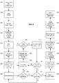
- FIG. 6 is a flow diagram illustrating an example process for determining an optimal autoexposure line rate in a fluorescence scanner system according to an embodiment of the invention.
- the illustrated processes can be implemented by the fluorescence scanning system 40 previously described with respect to FIGS. 1-3 .
- determining an optimal exposure time using the illustrated process can also be implemented by a conventional image tiling system that employs an area scan camera.
- fluorescence digital slide imaging captures light emitted from the sample 230 and the intensity of the emitted light can vary by orders of magnitude from slide to slide, it is necessary to determine the optimal exposure time for capturing the emitted light during scanning and digitizing the sample 230.
- saturated pixels in fluorescence digital imaging present a particular problem because they are brighter than other pixels and therefore are meaningless in the resulting image data because they do not have any linear correlation with pixels that are not saturated and as a result do not yield accurate data.
- determining the optimal exposure time for a particular sample 230 it is also important to maximize the dynamic range of the resulting image because underexposed images may not provide sufficient differences in the pixel intensities to be identifiable. Accordingly, determining an optimal autoexposure line rate in a fluorescence scanner system needs to minimize saturation while maximizing pixel intensities.
- the sample 230 is focused as shown in step 530. Focusing the sample may be accomplished by the process previously described with respect to FIG. 4 or FIG. 5 or both.
- a small region of the sample 230 is identified and scanned at the initial line rate (i.e., exposure time) and the image data from the scan is stored in a data storage area (e.g., an image buffer) as shown in step 540.
- the small region of the sample 230 may be approximately 1mm x 1mm and the initial line rate that is used can be determined in the focus process of step 530.
- the optimal exposure time for the scanned image data captured in the image buffer is determined and the line rate is adjusted accordingly.
- the process of scanning a small region of the sample 230 and determining the optimal exposure time and adjusting the line rate then iterates until the intensity level of the captured pixels is at its highest (with minimal saturation of pixels).
- the line rate is then identified in step 565 as the optimum line rate for the optimal exposure time when creating a digital slide image of the fluorescence sample 230.
- the histogram of the image data captured in the image buffer also approximates a Poisson distribution. Furthermore, because a primary objective of determining the optimal line rate (i.e., the optimal exposure) is to limit the number of saturated pixels, only the downward slope of the histogram is considered.
- the scanning system 40 treats the distribution of the histogram as an exponential decay function such that each non-zero value in the histogram is scaled by taking the base-2 logarithm, which results in a logarithmically scaled histogram approximating a line segment, as shown in step 545.
- a linear regression analysis is performed on the scaled histogram to yield a linear trend line with a negative slope and the intersection of the histogram with the intensity axis is determined by locating the x-intercept of the trend line, as shown in step 550.
- the x-intercept represents the intensity at which the number of pixels with this intensity is zero and is determined by using the slope of the trend line and the y-intercept.
- the intersection of the histogram and the intensity axis is determined for the scanned image data, it is compared against the optimal value representing a pixel intensity slightly below the saturation point of the TDI line scan camera 205. If the image data is within a predetermined (e.g., user configurable) tolerance of the saturation point of the TDI line scan camera 205, as determined in step 555, the image is considered well-exposed and the current line rate is identified as the optimal exposure time / optimum line rate as shown in step 565.
- a predetermined (e.g., user configurable) tolerance of the saturation point of the TDI line scan camera 205 as determined in step 555, the image is considered well-exposed and the current line rate is identified as the optimal exposure time / optimum line rate as shown in step 565.
- the ratio of optimal peak intensity to actual peak intensity is calculated and in step 560 the exposure time (i.e., line rate) of the TDI line scan camera 205 is adjusted using that ratio. The process then iterates until the optimum line rate is identified.
- FIG. 7 is a flow diagram illustrating an example process for acquiring images for shading correction according to the present invention.
- the illustrated processes can be implemented by the fluorescence scanning system 40 previously described with respect to FIGS. 1-3 .
- shading correction of fluorescence digital slide images compensates for the loss of illumination light (e.g., by roll off) that is necessary to acquire images with minimal shading artifacts on the edges of stripes.
- the illumination profile is determined based on the background fluorescence of a slide with a fluorescence sample 230.
- the illumination light profile can be determined using a clear point under the cover slip of the slide.
- the clear point is in an area of the slide that does not contain any fluorescence labeled sample 230. Accordingly, the light profile acquired from the background fluorescence can be used to compensate for illumination light roll off.
- step 580 the image of the sample 230 is brought into focus. This can be accomplished by the previously described macro focus or autofocus process. In one embodiment, in step 580 at least three focus points are identified on the sample 230. Because the illumination profile of the sample 230 varies depending on the height of the objective lens 225 above the sample 230, which is based on the focus.
- step 585 the initial line rate is set at the lowest value and a small region of the sample 230 is scanned in step 590 and the resulting digital image data is stored in a data storage area (e.g., an image buffer).
- the size of the scan area can vary. Setting the initial line rate for the highest possible exposure time is advantageous because the background material often has a low fluorescence emission.
- step 595 the average intensity of the image data is calculated. If the average intensity is not within a predetermined range, as determined in step 600, the line rate is adjusted in step 605 and the process iterates back to re-scan the small region of the sample 230.
- the adjusted line rate is selected based on a linear mapping of the average intensity calculated in step 595 using the previous line rate.
- the adjusted line rate is between the line rate that yields the minimum acceptable average intensity and the line rate that yields the maximum acceptable average intensity.
- an acceptable predetermined average intensity range is 80-600.
- determining that the average intensity is with the predetermined range rejects saturated images while also including low end images with average pixel intensities that are higher than the noise level of the TDI line scan camera 205.
- the light profile for shading correction that is created in step 610 is used to compensate for illumination light during scanning.
- pixel correction coefficients can be determined based on the light profile.
- the light profile is normalized to the brightest pixel value, which normally appears in the middle of the profile, and then a coefficient or pixel multiplier is calculated for all pixels within the field of view of the TDI line scan camera 205.
- the above described shading correction can advantageously be performed for all channels of the sample 230.
- an outlier rejection algorithm is employed when shading correction creates a specked image. This is useful when it is not possible or very difficult to locate a clear (i.e., fluorochrome free area) on the sample 230.
- the outlier rejection algorithm advantageously discards artifacts in the shading corrected image by rejecting pixels that exceed the median of the pixel values in each column. In one embodiment, pixels that are 20 counts higher than the median pixel value are rejected.
- FIG. 8 is a flow diagram illustrating an example scanning workflow process according to the present invention.
- the illustrated processes can be implemented by the fluorescence scanning system 40 previously described with respect to FIGS. 1-3 .
- the scanning system and its excitation filters and emission filters/turrets are configured in accordance with the type of sample 230 being scanned into a digital slide image and the various fluorochromes that the sample 230 might be marked with. In one embodiment, such configuration can be accomplished through a system console or a remote operator station. Additionally, the excitation filters and emission filters / Dichroic mirrors and their relative positions on the filter wheel or turret are identified in step 650.
- step 655 the sample is loaded. This can include placing the microscope slide upon which the sample is disposed into the scanning system 40.
- a macro image of the sample is acquired in step 660, for example using the process previously described with respect to FIG. 2 .
- the macro image is analyzed to identify a shading correction point as shown in step 665 and to determine the area(s) on the slide that contain tissue, as illustrated in step 670.
- the various fluorochromes on the sample 230 are identified and correlated to the correct combination of excitation and emission filters to scan the sample 230 at the various channels corresponding to the various fluorochromes.
- the scanning workflow automatically identifies the optimum exposure time for each channel, as previously described with respect to FIG. 6 . Accordingly, in step 680, the autoexposure process is initiated and the number of channels is determined. In step 685, the autoexposure process is performed. Autoexposure can be automatically performed on all channels or it can be performed on one channel.
- steps 690 and 720 an operator may be engaged to accept the autoexposure results and confirm that all channels have been processed and a valid exposure time determined for each channel.
- the scanning system 40 may automatically proceed through steps 690 to 720 until an optimal exposure time has been calculated for each channel with no operator input.
- step 725 the scanning system 40 identifies a set of XY focus points on the sample 230.
- the scanning system visits each XY focus point in the set and determines the optimal focus height at each of the XY focus points.
- the focus points (comprising an XY location and the optimal focus height) are then combined to create a focus map that covers the surface of the sample 230.
- step 735 the shading correction information is determined for each of the channels.
- the scanning system 40 begins to scan the sample 230 at each channel, as shown in step 740.
- the digital image data generated by the scan for each channel is stored in a data storage area in step 745 and then a digital slide image having image data for all of the channels is created in step 750. Finally, the fluorescence digital slide image is stored in a data storage area.
- autofocusing can be interleaved with the scanning process such that the focus points and focus map information are generated for a particular stripe just before that stripe is scanned. Additionally, autofocusing can be done for just a single channel or can be done for each channel.
- TDI line scan camera 205 is employed by the fluorescence scanning system 40, only one channel at a time is scanned.
- the use of motorized filter wheels allows a single stripe to be scanned multiple times sequentially, once for each channel. In other words, each channel of a single stripe is captured before moving to the next stripe.
- the scanning system 40 uses separate excitation and emission filters, only the excitation filter needs to be rotated to automatically scan the multi-channel sample 230 in the preferred Pinkel configuration described above (multi-band filter cube and single band excitation filters).
- scanning each channel of a single stripe before moving to the next stripe ensures that the resulting image data is optimally registered across all of the channels.
- the number of filter changes is also minimized in comparison to conventional image tiling systems.
- some or all channels of a sample can be scanned using single band filter cubes having single band excitation/emission filters and Dichroic mirrors.
- multiple monochrome digital slide images are created that correspond to the number of channels on a sample. These images are stored in a single digital slide image file or alternatively can be stored as separate image files along with an index file that relates the various separate image files.
- a fused image which is a composite image of all channels with selected false colors can be created.
- Various embodiments of the fluorescence scanning system 40 described herein can be implemented using a combination of both hardware modules and software modules.
- programmed software modules, application specific integrated circuits or field programmable gate arrays can be used interchangeably to implement certain functional modules of the scanning system 40.
- the various illustrative modules, blocks, and steps described in connection with all of the figures and the various embodiments disclosed herein can be implemented as hardware, software or a combination of the two.
- the various illustrative modules, blocks, and steps have been described above in terms of their functionality and whether such functionality is implemented as hardware or software or a combination of the two depends upon the particular application and design constraints imposed on the overall system.
Landscapes
- Physics & Mathematics (AREA)
- General Physics & Mathematics (AREA)
- Engineering & Computer Science (AREA)
- Chemical & Material Sciences (AREA)
- Analytical Chemistry (AREA)
- Health & Medical Sciences (AREA)
- Optics & Photonics (AREA)
- General Health & Medical Sciences (AREA)
- Life Sciences & Earth Sciences (AREA)
- Multimedia (AREA)
- Computer Vision & Pattern Recognition (AREA)
- Theoretical Computer Science (AREA)
- Nuclear Medicine, Radiotherapy & Molecular Imaging (AREA)
- Biochemistry (AREA)
- Immunology (AREA)
- Pathology (AREA)
- Biomedical Technology (AREA)
- Molecular Biology (AREA)
- General Engineering & Computer Science (AREA)
- Signal Processing (AREA)
- Investigating, Analyzing Materials By Fluorescence Or Luminescence (AREA)
- Microscoopes, Condenser (AREA)
- Eye Examination Apparatus (AREA)
Applications Claiming Priority (3)
| Application Number | Priority Date | Filing Date | Title |
|---|---|---|---|
| US10843108P | 2008-10-24 | 2008-10-24 | |
| PCT/US2009/061957 WO2010048584A2 (en) | 2008-10-24 | 2009-10-23 | Whole slide fluorescence scanner |
| EP09822817.4A EP2344864B1 (de) | 2008-10-24 | 2009-10-23 | Komplett verschiebbarer fluoreszenz-scanner |
Related Parent Applications (1)
| Application Number | Title | Priority Date | Filing Date |
|---|---|---|---|
| EP09822817.4A Division EP2344864B1 (de) | 2008-10-24 | 2009-10-23 | Komplett verschiebbarer fluoreszenz-scanner |
Publications (2)
| Publication Number | Publication Date |
|---|---|
| EP3764085A2 true EP3764085A2 (de) | 2021-01-13 |
| EP3764085A3 EP3764085A3 (de) | 2021-03-24 |
Family
ID=42120014
Family Applications (2)
| Application Number | Title | Priority Date | Filing Date |
|---|---|---|---|
| EP09822817.4A Active EP2344864B1 (de) | 2008-10-24 | 2009-10-23 | Komplett verschiebbarer fluoreszenz-scanner |
| EP20172920.9A Withdrawn EP3764085A3 (de) | 2008-10-24 | 2009-10-23 | Fluoreszenz-scanner mit komplettobjektträger |
Family Applications Before (1)
| Application Number | Title | Priority Date | Filing Date |
|---|---|---|---|
| EP09822817.4A Active EP2344864B1 (de) | 2008-10-24 | 2009-10-23 | Komplett verschiebbarer fluoreszenz-scanner |
Country Status (4)
| Country | Link |
|---|---|
| US (2) | US8743195B2 (de) |
| EP (2) | EP2344864B1 (de) |
| JP (3) | JP5643210B2 (de) |
| WO (1) | WO2010048584A2 (de) |
Families Citing this family (59)
| Publication number | Priority date | Publication date | Assignee | Title |
|---|---|---|---|---|
| US8055034B2 (en) * | 2006-09-13 | 2011-11-08 | Fluidigm Corporation | Methods and systems for image processing of microfluidic devices |
| EP2344864B1 (de) | 2008-10-24 | 2020-05-06 | Leica Biosystems Imaging, Inc. | Komplett verschiebbarer fluoreszenz-scanner |
| US20100157086A1 (en) | 2008-12-15 | 2010-06-24 | Illumina, Inc | Dynamic autofocus method and system for assay imager |
| JP5499732B2 (ja) * | 2009-06-23 | 2014-05-21 | ソニー株式会社 | 生体サンプル像取得装置、生体サンプル像取得方法及び生体サンプル像取得プログラム |
| JP5672688B2 (ja) * | 2009-10-23 | 2015-02-18 | ソニー株式会社 | 合焦装置、合焦方法、合焦プログラム及び顕微鏡 |
| CN103210338A (zh) * | 2010-08-30 | 2013-07-17 | 三洋电机株式会社 | 观察装置、观察程序及观察系统 |
| CA2809526C (en) | 2010-10-22 | 2014-01-14 | William Gelbart | Automated slide scanning system for a microscope |
| US8774518B2 (en) | 2011-08-02 | 2014-07-08 | Nec Laboratories America, Inc. | Digital pathology system with low-latency analytics |
| TW201315202A (zh) * | 2011-09-30 | 2013-04-01 | Smobio Inc | 掃描裝置 |
| JP6309459B2 (ja) * | 2012-02-15 | 2018-04-11 | ヘプタゴン・マイクロ・オプティクス・ピーティーイー・エルティーディーHeptagon Micro Optics Pte.Ltd. | ストライプ照明の飛行時間型カメラ |
| WO2013165576A1 (en) * | 2012-05-02 | 2013-11-07 | Aperio Technologies, Inc. | Real-time focusing in line scan imaging |
| US9836865B2 (en) * | 2012-12-06 | 2017-12-05 | Ge Healthcare Biosciences Corp. | Systems and methods for split screen display of biological specimen and for capturing records thereof |
| JP2014178474A (ja) * | 2013-03-14 | 2014-09-25 | Sony Corp | デジタル顕微鏡装置、その合焦位置探索方法およびプログラム |
| US10088658B2 (en) | 2013-03-18 | 2018-10-02 | General Electric Company | Referencing in multi-acquisition slide imaging |
| WO2014148419A1 (ja) * | 2013-03-19 | 2014-09-25 | 独立行政法人理化学研究所 | 核酸配列決定用のフローセル |
| WO2014175219A1 (ja) | 2013-04-26 | 2014-10-30 | 浜松ホトニクス株式会社 | 画像取得装置、試料の合焦点情報を取得する方法及びシステム |
| US9661212B2 (en) | 2013-04-26 | 2017-05-23 | Hamamatsu Photonics K.K. | Image acquisition device and focusing method for image acquisition device |
| US10348954B2 (en) | 2013-04-26 | 2019-07-09 | Hamamatsu Photonics K.K. | Image acquisition device and method and system for creating focus map for specimen |
| US9250431B2 (en) * | 2013-09-05 | 2016-02-02 | Excelitas Canada, Inc. | Diffusing collection lens for direct coupled high power microscopy illumination systems |
| CN105794192B (zh) * | 2013-11-06 | 2019-03-08 | 统雷有限公司 | 用于对异步触发采集到的图像进行校正的方法 |
| JP2015125177A (ja) | 2013-12-25 | 2015-07-06 | ソニー株式会社 | 顕微鏡システムおよびその画像データ転送方法 |
| JP6171970B2 (ja) * | 2014-02-10 | 2017-08-02 | ソニー株式会社 | レーザ走査型顕微鏡装置および制御方法 |
| EP3213137A4 (de) * | 2014-10-29 | 2018-05-02 | Lumencor, Inc. | Integriertes fluoreszenzabtastsystem |
| BR112017009409A2 (pt) | 2015-03-12 | 2017-12-19 | Koninklijke Philips Nv | unidade de iluminação para digitalizador de patologia digital, e, digitalizador de patologia digital |
| DE102016109945A1 (de) * | 2015-11-05 | 2017-05-11 | Leica Microsystems Cms Gmbh | Mikroskop für die Durchlicht- und Fluoreszenzmikroskopie |
| JP2019514078A (ja) * | 2016-03-10 | 2019-05-30 | ヴィズビット インコーポレイテッド | 時間多重化プログラム可能な視野撮像 |
| US10551608B2 (en) | 2016-03-24 | 2020-02-04 | Molecular Devices, Llc | Imaging system with ancillary image detector for sample location |
| JP6654688B2 (ja) * | 2016-03-25 | 2020-02-26 | オリンパス株式会社 | 顕微鏡観察システム、顕微鏡観察方法、及び顕微鏡観察プログラム |
| LU93021B1 (de) * | 2016-04-08 | 2017-11-08 | Leica Microsystems | Verfahren und Mikroskop zum Untersuchen einer Probe |
| KR101856073B1 (ko) * | 2016-10-04 | 2018-05-10 | 온스캔스주식회사 | 3차원 스캐닝 방법 및 그 장치 |
| JP6423841B2 (ja) | 2016-10-11 | 2018-11-14 | 浜松ホトニクス株式会社 | 試料観察装置及び試料観察方法 |
| US11506877B2 (en) | 2016-11-10 | 2022-11-22 | The Trustees Of Columbia University In The City Of New York | Imaging instrument having objective axis and light sheet or light beam projector axis intersecting at less than 90 degrees |
| US10554899B2 (en) * | 2016-12-16 | 2020-02-04 | Goodrich Corporation | HDR imaging |
| US10409049B2 (en) | 2016-12-30 | 2019-09-10 | Leica Biosystems Imaging, Inc. | Low resolution slide imaging and slide label imaging and high resolution slide imaging using dual optical paths and a single imaging sensor |
| KR102246166B1 (ko) * | 2017-03-30 | 2021-04-28 | 후지필름 가부시키가이샤 | 관찰 장치 및 관찰 제어 방법과 관찰 제어 프로그램 |
| JP6993100B2 (ja) * | 2017-04-27 | 2022-01-13 | オリンパス株式会社 | 観察装置および観察方法 |
| JP7068354B2 (ja) * | 2017-06-28 | 2022-05-16 | ヴェンタナ メディカル システムズ, インク. | システムレベル較正 |
| EP4254037A3 (de) | 2017-09-29 | 2023-12-27 | Leica Biosystems Imaging, Inc. | Echtzeit-autofokus-scanning |
| US10502941B2 (en) | 2017-09-29 | 2019-12-10 | Leica Biosystmes Imaging, Inc. | Two-dimensional and three-dimensional fixed Z scanning |
| CN111164484B (zh) * | 2017-09-29 | 2022-07-29 | 徕卡生物系统成像股份有限公司 | 双程微距图像 |
| US10459193B2 (en) | 2017-09-29 | 2019-10-29 | Leica Biosystems Imaging, Inc. | Real-time autofocus focusing algorithm |
| WO2019065144A1 (ja) * | 2017-09-29 | 2019-04-04 | 富士フイルム株式会社 | 観察装置、観察方法および観察プログラム |
| CN109874335B (zh) * | 2017-10-02 | 2022-06-10 | 特励达数字成像有限公司 | 对线扫描相机进行同步的方法 |
| WO2019071042A1 (en) * | 2017-10-04 | 2019-04-11 | Leica Biosystems Imaging, Inc. | CARROUSEL FOR SLIDES 2X3 AND 1X3 |
| AU2018375358B2 (en) * | 2017-11-28 | 2021-02-04 | Leica Biosystems Imaging, Inc. | Dual processor image processing |
| WO2019109034A1 (en) * | 2017-11-30 | 2019-06-06 | Leica Biosystems Imaging, Inc. | Impulse rescan system |
| JP6856559B2 (ja) * | 2018-01-23 | 2021-04-07 | 浜松ホトニクス株式会社 | 光測定装置及び光測定方法 |
| IL264937B (en) * | 2018-02-25 | 2022-09-01 | Orbotech Ltd | Range differences for self-focusing in optical imaging systems |
| CN109272575B (zh) * | 2018-09-28 | 2022-06-28 | 麦克奥迪实业集团有限公司 | 一种提高数字切片扫描仪建模速度的方法 |
| WO2020091965A2 (en) | 2018-11-02 | 2020-05-07 | Hologic, Inc. | Digital imaging system and method |
| JP7348730B2 (ja) * | 2019-02-22 | 2023-09-21 | シスメックス株式会社 | 試料測定装置および試料測定方法 |
| DE102019127775A1 (de) * | 2019-10-15 | 2021-04-15 | Carl Zeiss Microscopy Gmbh | Lichtmikroskop und Verfahren zur Bildaufnahme mit einem Lichtmikroskop |
| CN112652360A (zh) * | 2020-12-15 | 2021-04-13 | 苏州缔因安生物科技有限公司 | 一种数字pcr荧光信号获取方法、装置、设备及存储介质 |
| CN114414545B (zh) * | 2022-01-21 | 2024-03-05 | 江苏禹视科技有限公司 | 一种荧光扫描检测系统和方法 |
| WO2024006284A1 (en) * | 2022-07-01 | 2024-01-04 | Illumina Cambridge Limited | Multiband scanning and fiber bundle to enable reduced light source intensity and improved imaging quality |
| US20240035967A1 (en) * | 2022-07-29 | 2024-02-01 | Applied Materials, Inc. | Time delay integration acquisition for spatial genomics imaging |
| WO2024031069A1 (en) * | 2022-08-04 | 2024-02-08 | Applied Materials, Inc. | High-throughput spatial imaging system for biological samples |
| CN116400490B (zh) * | 2023-06-08 | 2023-08-25 | 杭州华得森生物技术有限公司 | 荧光显微成像系统及其方法 |
| CN116754565B (zh) * | 2023-08-04 | 2024-04-26 | 哈尔滨工业大学 | 一种光学元件全口径表面微缺陷光致荧光检测用自动对焦检测方法 |
Family Cites Families (121)
| Publication number | Priority date | Publication date | Assignee | Title |
|---|---|---|---|---|
| US3643015A (en) | 1970-06-19 | 1972-02-15 | Paul Davidovits | Scanning optical microscope |
| US4926489A (en) | 1983-03-11 | 1990-05-15 | Kla Instruments Corporation | Reticle inspection system |
| US4742558A (en) | 1984-02-14 | 1988-05-03 | Nippon Telegraph & Telephone Public Corporation | Image information retrieval/display apparatus |
| DE3577355D1 (de) | 1984-06-25 | 1990-05-31 | Olympus Optical Co | Mikroskop. |
| US4700298A (en) | 1984-09-14 | 1987-10-13 | Branko Palcic | Dynamic microscope image processing scanner |
| US4672559A (en) | 1984-12-26 | 1987-06-09 | E. I. Du Pont De Nemours And Company | Method for operating a microscopical mapping system |
| US4760385A (en) | 1985-04-22 | 1988-07-26 | E. I. Du Pont De Nemours And Company | Electronic mosaic imaging process |
| US4673988A (en) | 1985-04-22 | 1987-06-16 | E.I. Du Pont De Nemours And Company | Electronic mosaic imaging process |
| US4777525A (en) | 1985-12-23 | 1988-10-11 | Preston Jr Kendall | Apparatus and method for a multi-resolution electro-optical imaging, display and storage/retrieval system |
| US4845552A (en) | 1987-08-20 | 1989-07-04 | Bruno Jaggi | Quantitative light microscope using a solid state detector in the primary image plane |
| US4806015A (en) | 1987-12-08 | 1989-02-21 | Cottingham Hugh V | Agglutination detection apparatus |
| US5740270A (en) | 1988-04-08 | 1998-04-14 | Neuromedical Systems, Inc. | Automated cytological specimen classification system and method |
| JP2749069B2 (ja) | 1988-04-26 | 1998-05-13 | オリンパス光学工業株式会社 | 蛍光顕微鏡装置 |
| DE68924460T2 (de) | 1988-10-11 | 1996-06-13 | Du Pont | Laserabtastmikroskop und Anwendungsverfahren. |
| US5067152A (en) | 1989-01-30 | 1991-11-19 | Information Technologies Research, Inc. | Method and apparatus for vector quantization |
| US4960999A (en) | 1989-02-13 | 1990-10-02 | Kms Fusion, Inc. | Scanning and storage of electrophoretic records |
| US4987480A (en) | 1989-07-11 | 1991-01-22 | Massachusetts Institute Of Technology | Multiscale coding of images |
| US5086477A (en) | 1990-08-07 | 1992-02-04 | Northwest Technology Corp. | Automated system for extracting design and layout information from an integrated circuit |
| JP2991483B2 (ja) | 1990-11-27 | 1999-12-20 | 日本分光工業株式会社 | 顕微鏡イメージマッピング装置及び方法 |
| US5784162A (en) | 1993-08-18 | 1998-07-21 | Applied Spectral Imaging Ltd. | Spectral bio-imaging methods for biological research, medical diagnostics and therapy |
| US5231663A (en) | 1991-03-18 | 1993-07-27 | Earl Joseph G | Image processing system |
| US5185638A (en) | 1991-04-26 | 1993-02-09 | International Business Machines Corporation | Computer controlled, multiple angle illumination system |
| US5187754A (en) | 1991-04-30 | 1993-02-16 | General Electric Company | Forming, with the aid of an overview image, a composite image from a mosaic of images |
| KR960007481B1 (ko) | 1991-05-27 | 1996-06-03 | 가부시끼가이샤 히다찌세이사꾸쇼 | 패턴검사방법 및 장치 |
| US5790710A (en) | 1991-07-12 | 1998-08-04 | Jeffrey H. Price | Autofocus system for scanning microscopy |
| JPH0576005A (ja) | 1991-09-13 | 1993-03-26 | Nikon Corp | 画像入力装置 |
| US5172228A (en) | 1991-11-19 | 1992-12-15 | Utah State University Foundation | Image compression method and apparatus employing distortion adaptive tree search vector quantization |
| US5495535A (en) | 1992-01-31 | 1996-02-27 | Orbotech Ltd | Method of inspecting articles |
| US5912699A (en) | 1992-02-18 | 1999-06-15 | Neopath, Inc. | Method and apparatus for rapid capture of focused microscopic images |
| US5448399A (en) | 1992-03-13 | 1995-09-05 | Park Scientific Instruments | Optical system for scanning microscope |
| JPH05264221A (ja) | 1992-03-17 | 1993-10-12 | Fujitsu Ltd | 半導体露光装置用マーク位置検出装置及びこれを用いた半導体露光装置用位置合わせ装置 |
| JPH05316302A (ja) | 1992-05-13 | 1993-11-26 | Minolta Camera Co Ltd | 画像入力装置 |
| JP3275368B2 (ja) | 1992-07-09 | 2002-04-15 | 株式会社ニコン | 露光方法及び装置 |
| US5650813A (en) | 1992-11-20 | 1997-07-22 | Picker International, Inc. | Panoramic time delay and integration video camera system |
| US5633948A (en) | 1992-11-30 | 1997-05-27 | Kegelmeyer, Jr.; W. Philip | Method and apparatus for detecting a desired behavior in digital image data |
| US5479252A (en) | 1993-06-17 | 1995-12-26 | Ultrapointe Corporation | Laser imaging system for inspection and analysis of sub-micron particles |
| US5923430A (en) | 1993-06-17 | 1999-07-13 | Ultrapointe Corporation | Method for characterizing defects on semiconductor wafers |
| US5483055A (en) | 1994-01-18 | 1996-01-09 | Thompson; Timothy V. | Method and apparatus for performing an automatic focus operation for a microscope |
| US5793969A (en) | 1993-07-09 | 1998-08-11 | Neopath, Inc. | Network review and analysis of computer encoded slides |
| US5434629A (en) | 1993-12-20 | 1995-07-18 | Focus Automation Systems Inc. | Real-time line scan processor |
| GB2286309B (en) | 1994-02-01 | 1998-04-15 | Rank Cintel Ltd | High resolution film scanner |
| US5578832A (en) | 1994-09-02 | 1996-11-26 | Affymetrix, Inc. | Method and apparatus for imaging a sample on a device |
| JPH07243823A (ja) | 1994-03-03 | 1995-09-19 | Toshiba Corp | パターン検査装置 |
| US5932872A (en) | 1994-07-01 | 1999-08-03 | Jeffrey H. Price | Autofocus system for scanning microscopy having a volume image formation |
| US5489772A (en) * | 1994-11-14 | 1996-02-06 | Hewlett-Packard Company | Variable optical sampling rate dependent on requested scan resolution |
| US5649032A (en) | 1994-11-14 | 1997-07-15 | David Sarnoff Research Center, Inc. | System for automatically aligning images to form a mosaic image |
| WO1996039619A1 (en) | 1995-06-06 | 1996-12-12 | Kla Instruments Corporation | Optical inspection of a specimen using multi-channel responses from the specimen |
| US5922282A (en) | 1995-06-07 | 1999-07-13 | Ledley; Robert S. | Super fast tuberculosis diagnosis and sensitivity testing method |
| AU713854B2 (en) | 1995-07-19 | 1999-12-09 | Veracel Inc. | Automated scanning of microscope slides |
| JPH10511531A (ja) | 1995-10-18 | 1998-11-04 | フィリップス エレクトロニクス ネムローゼ フェンノートシャップ | 領域ベーステクスチュアコード化方法及びデコード方法、及び対応するシステム |
| US5710835A (en) | 1995-11-14 | 1998-01-20 | The Regents Of The University Of California, Office Of Technology Transfer | Storage and retrieval of large digital images |
| US6151405A (en) | 1996-11-27 | 2000-11-21 | Chromavision Medical Systems, Inc. | System and method for cellular specimen grading |
| JP2000501184A (ja) | 1995-11-30 | 2000-02-02 | クロマビジョン メディカル システムズ,インコーポレイテッド | 生体標本の自動画像分析の方法および装置 |
| JPH09197290A (ja) | 1996-01-12 | 1997-07-31 | Omron Corp | 顕微鏡画像入力装置 |
| US6005964A (en) | 1996-01-24 | 1999-12-21 | The Board Of Trustees Of The University Of Illinois | Automatic machine vision microscope slide inspection system and method |
| US5872591A (en) | 1996-02-21 | 1999-02-16 | Pakon, Inc. | Film scanner |
| JPH09247545A (ja) | 1996-03-11 | 1997-09-19 | Matsushita Electric Ind Co Ltd | スキャナ型電子カメラ |
| US6078681A (en) | 1996-03-18 | 2000-06-20 | Marine Biological Laboratory | Analytical imaging system and process |
| US6091846A (en) | 1996-05-31 | 2000-07-18 | Texas Instruments Incorporated | Method and system for anomaly detection |
| WO1998002843A1 (en) | 1996-07-12 | 1998-01-22 | Erim International, Inc. | Mosaic construction, processing, and review of very large electronic micrograph composites |
| US6272235B1 (en) | 1997-03-03 | 2001-08-07 | Bacus Research Laboratories, Inc. | Method and apparatus for creating a virtual microscope slide |
| US6031930A (en) | 1996-08-23 | 2000-02-29 | Bacus Research Laboratories, Inc. | Method and apparatus for testing a progression of neoplasia including cancer chemoprevention testing |
| US5754291A (en) | 1996-09-19 | 1998-05-19 | Molecular Dynamics, Inc. | Micro-imaging system |
| GB9622055D0 (en) | 1996-10-23 | 1996-12-18 | Univ Strathclyde | Vector quantisation |
| AU733511B2 (en) | 1996-11-08 | 2001-05-17 | National Computer Systems, Inc. | Optical scanning with calibrated pixel output |
| US5968731A (en) | 1996-12-10 | 1999-10-19 | The Regents Of The University Of California | Apparatus for automated testing of biological specimens |
| US20010017941A1 (en) | 1997-03-14 | 2001-08-30 | Navin Chaddha | Method and apparatus for table-based compression with embedded coding |
| DE19714221A1 (de) | 1997-04-07 | 1998-10-08 | Zeiss Carl Fa | Konfokales Mikroskop mit einem motorischen Scanningtisch |
| US6169816B1 (en) | 1997-05-14 | 2001-01-02 | Applied Imaging, Inc. | Identification of objects of interest using multiple illumination schemes and finding overlap of features in corresponding multiple images |
| US6002789A (en) | 1997-06-24 | 1999-12-14 | Pilot Industries, Inc. | Bacteria colony counter and classifier |
| US5895915A (en) | 1997-07-24 | 1999-04-20 | General Scanning, Inc. | Bi-directional scanning system with a pixel clock system |
| US6262838B1 (en) | 1998-03-20 | 2001-07-17 | Genetic Microsystems Inc | Focusing in microscope systems |
| JP3824116B2 (ja) | 1998-01-29 | 2006-09-20 | 日本電信電話株式会社 | 顕微鏡画像遠隔制御システム |
| CA2229175A1 (en) | 1998-02-06 | 1999-08-06 | Morphometrix Technologies Inc. | Automatic focus system |
| US20030036855A1 (en) * | 1998-03-16 | 2003-02-20 | Praelux Incorporated, A Corporation Of New Jersey | Method and apparatus for screening chemical compounds |
| US6185030B1 (en) | 1998-03-20 | 2001-02-06 | James W. Overbeck | Wide field of view and high speed scanning microscopy |
| US5943122A (en) | 1998-07-10 | 1999-08-24 | Nanometrics Incorporated | Integrated optical measurement instruments |
| US6316774B1 (en) * | 1998-08-18 | 2001-11-13 | Molecular Devices Corporation | Optical system for a scanning fluorometer |
| JP3139998B2 (ja) | 1998-12-01 | 2001-03-05 | 株式会社東京精密 | 外観検査装置及び方法 |
| US6330348B1 (en) | 1999-01-21 | 2001-12-11 | Resolution Sciences Corporation | Method and apparatus for measurement of microtome performance |
| US6249341B1 (en) | 1999-01-25 | 2001-06-19 | Amnis Corporation | Imaging and analyzing parameters of small moving objects such as cells |
| JP4323608B2 (ja) | 1999-03-12 | 2009-09-02 | キヤノン株式会社 | 露光装置およびデバイス製造方法 |
| US7106895B1 (en) | 1999-05-05 | 2006-09-12 | Kla-Tencor | Method and apparatus for inspecting reticles implementing parallel processing |
| JP3544892B2 (ja) | 1999-05-12 | 2004-07-21 | 株式会社東京精密 | 外観検査方法及び装置 |
| US7212667B1 (en) | 1999-05-17 | 2007-05-01 | Samsung Electronics Co., Ltd. | Color image processing method for indexing an image using a lattice structure |
| JP2001093455A (ja) | 1999-09-21 | 2001-04-06 | Nikon Corp | 電子ビーム装置 |
| US6594401B1 (en) | 1999-10-20 | 2003-07-15 | Xerox Corporation | Detection and elimination of scanning artifacts |
| JP2001210263A (ja) | 2000-01-27 | 2001-08-03 | Hitachi Ltd | 走査電子顕微鏡、そのダイナミックフォーカス制御方法および半導体デバイスの表面および断面形状の把握方法 |
| US7518652B2 (en) * | 2000-05-03 | 2009-04-14 | Aperio Technologies, Inc. | Method and apparatus for pre-focus in a linear array based slide scanner |
| US6711283B1 (en) | 2000-05-03 | 2004-03-23 | Aperio Technologies, Inc. | Fully automatic rapid microscope slide scanner |
| JP2002042706A (ja) | 2000-07-25 | 2002-02-08 | Hitachi Ltd | 走査電子顕微鏡の自動焦点機能 |
| US6763140B1 (en) | 2000-09-07 | 2004-07-13 | Chipworks | Method and apparatus for focusing a micro-imaging system onto a tilted or uneven sample to acquire images of the sample |
| US7155049B2 (en) | 2001-01-11 | 2006-12-26 | Trestle Acquisition Corp. | System for creating microscopic digital montage images |
| JP2003023496A (ja) | 2001-07-06 | 2003-01-24 | Ntt Communications Kk | 音声情報提供方法及び装置及び音声情報提供プログラム及び音声情報提供プログラムを格納した記憶媒体 |
| US7338168B2 (en) | 2001-07-06 | 2008-03-04 | Palantyr Research, Llc | Particle analyzing system and methodology |
| JP3999479B2 (ja) * | 2001-07-10 | 2007-10-31 | オリンパス株式会社 | 光学装置 |
| WO2003014795A1 (en) * | 2001-08-06 | 2003-02-20 | Bioview Ltd. | Image focusing in fluorescent imaging |
| WO2003014400A1 (en) * | 2001-08-08 | 2003-02-20 | Applied Precision, Llc | Time-delay integration imaging of biological specimens |
| US7283253B2 (en) * | 2002-03-13 | 2007-10-16 | Applied Precision, Llc | Multi-axis integration system and method |
| US7272252B2 (en) * | 2002-06-12 | 2007-09-18 | Clarient, Inc. | Automated system for combining bright field and fluorescent microscopy |
| DE10232242A1 (de) | 2002-07-17 | 2004-02-05 | Leica Microsystems Semiconductor Gmbh | Verfahren und Vorrichtung zum Rastern einer Probe mit einem optischen ab Bildungssystem |
| JP2004363085A (ja) | 2003-05-09 | 2004-12-24 | Ebara Corp | 荷電粒子線による検査装置及びその検査装置を用いたデバイス製造方法 |
| JP4194905B2 (ja) | 2003-08-18 | 2008-12-10 | 株式会社ノリタケカンパニーリミテド | 多孔質筒体の支持構造および支持部材の固着方法 |
| US7282180B2 (en) * | 2003-07-02 | 2007-10-16 | Immunivest Corporation | Devices and methods to image objects |
| GB0317679D0 (en) * | 2003-07-29 | 2003-09-03 | Amersham Biosciences Uk Ltd | Analysing biological entities |
| US20060247862A1 (en) * | 2003-09-08 | 2006-11-02 | Arini Nicholas S | Determining cell cycle phase data |
| JP4934281B2 (ja) * | 2004-02-09 | 2012-05-16 | オリンパス株式会社 | 全反射蛍光顕微鏡 |
| EP3410395B1 (de) * | 2004-05-27 | 2020-03-11 | Leica Biosystems Imaging, Inc. | System und verfahren zur bewertung der bildqualität virtueller objektträger |
| US7667764B2 (en) * | 2004-06-04 | 2010-02-23 | Konica Minolta Holdings, Inc. | Image sensing apparatus |
| JP4020893B2 (ja) * | 2004-07-07 | 2007-12-12 | オリンパス株式会社 | 顕微鏡撮像装置および生体試料観察システム |
| US20060018013A1 (en) | 2004-07-07 | 2006-01-26 | Yoshimasa Suzuki | Microscope imaging apparatus and biological-specimen examination system |
| JP2006030304A (ja) * | 2004-07-12 | 2006-02-02 | Nikon Corp | 顕微鏡の焦点検出装置 |
| JP2006039315A (ja) * | 2004-07-28 | 2006-02-09 | Hamamatsu Photonics Kk | 自動焦点装置及びそれを用いた顕微鏡装置 |
| JP4786207B2 (ja) * | 2005-03-17 | 2011-10-05 | 浜松ホトニクス株式会社 | 顕微鏡システム |
| US7768638B2 (en) * | 2005-03-18 | 2010-08-03 | Illumina, Inc. | Systems for and methods of facilitating focusing an optical scanner |
| WO2007038260A2 (en) * | 2005-09-23 | 2007-04-05 | Massachusetts Institute Of Technology | Systems and methods for force-fluorescence microscopy |
| EP1989583B1 (de) * | 2006-02-27 | 2017-07-19 | Leica Biosystems Imaging, Inc. | System und verfahren für einen einachsigen optischen objektträger-scanner mit mehreren abtastern |
| JP4917331B2 (ja) * | 2006-03-01 | 2012-04-18 | 浜松ホトニクス株式会社 | 画像取得装置、画像取得方法、及び画像取得プログラム |
| JP4663602B2 (ja) * | 2006-08-14 | 2011-04-06 | オリンパス株式会社 | 自動合焦装置、顕微鏡および自動合焦方法 |
| JP2008051772A (ja) * | 2006-08-28 | 2008-03-06 | Hamamatsu Photonics Kk | 蛍光画像取得装置、及び蛍光画像取得方法 |
| EP2344864B1 (de) | 2008-10-24 | 2020-05-06 | Leica Biosystems Imaging, Inc. | Komplett verschiebbarer fluoreszenz-scanner |
-
2009
- 2009-10-23 EP EP09822817.4A patent/EP2344864B1/de active Active
- 2009-10-23 EP EP20172920.9A patent/EP3764085A3/de not_active Withdrawn
- 2009-10-23 JP JP2011533391A patent/JP5643210B2/ja not_active Expired - Fee Related
- 2009-10-23 WO PCT/US2009/061957 patent/WO2010048584A2/en active Application Filing
- 2009-10-23 US US12/990,576 patent/US8743195B2/en active Active
-
2014
- 2014-03-17 JP JP2014054023A patent/JP5698398B2/ja not_active Expired - Fee Related
- 2014-05-12 US US14/275,529 patent/US9523844B2/en active Active
-
2015
- 2015-02-12 JP JP2015025564A patent/JP6100813B2/ja not_active Expired - Fee Related
Also Published As
| Publication number | Publication date |
|---|---|
| JP5643210B2 (ja) | 2014-12-17 |
| JP2012507009A (ja) | 2012-03-22 |
| EP2344864B1 (de) | 2020-05-06 |
| EP2344864A2 (de) | 2011-07-20 |
| US20140247379A1 (en) | 2014-09-04 |
| JP2014142657A (ja) | 2014-08-07 |
| WO2010048584A2 (en) | 2010-04-29 |
| US8743195B2 (en) | 2014-06-03 |
| JP2015111143A (ja) | 2015-06-18 |
| US9523844B2 (en) | 2016-12-20 |
| US20110115897A1 (en) | 2011-05-19 |
| JP6100813B2 (ja) | 2017-03-22 |
| JP5698398B2 (ja) | 2015-04-08 |
| WO2010048584A3 (en) | 2010-08-05 |
| EP2344864A4 (de) | 2018-01-24 |
| EP3764085A3 (de) | 2021-03-24 |
Similar Documents
| Publication | Publication Date | Title |
|---|---|---|
| EP2344864B1 (de) | Komplett verschiebbarer fluoreszenz-scanner | |
| US9366628B2 (en) | Standardizing fluorescence microscopy systems | |
| US10983305B2 (en) | Methods for correctly orienting a substrate in a microscope | |
| US10955650B2 (en) | Two pass macro image | |
| US11454781B2 (en) | Real-time autofocus focusing algorithm | |
| US11347044B2 (en) | Low resolution slide imaging and slide label imaging and high resolution slide imaging using dual optical paths and a single imaging sensor | |
| AU2007266783A1 (en) | Method and system for digitizing a specimen with fluorescent target points | |
| EP3884327B1 (de) | Echtzeitfokussierung in einem system zum scannen von objektträgern |
Legal Events
| Date | Code | Title | Description |
|---|---|---|---|
| PUAI | Public reference made under article 153(3) epc to a published international application that has entered the european phase |
Free format text: ORIGINAL CODE: 0009012 |
|
| STAA | Information on the status of an ep patent application or granted ep patent |
Free format text: STATUS: THE APPLICATION HAS BEEN PUBLISHED |
|
| AC | Divisional application: reference to earlier application |
Ref document number: 2344864 Country of ref document: EP Kind code of ref document: P |
|
| AK | Designated contracting states |
Kind code of ref document: A2 Designated state(s): AT BE BG CH CY CZ DE DK EE ES FI FR GB GR HR HU IE IS IT LI LT LU LV MC MK MT NL NO PL PT RO SE SI SK SM TR |
|
| PUAL | Search report despatched |
Free format text: ORIGINAL CODE: 0009013 |
|
| AK | Designated contracting states |
Kind code of ref document: A3 Designated state(s): AT BE BG CH CY CZ DE DK EE ES FI FR GB GR HR HU IE IS IT LI LT LU LV MC MK MT NL NO PL PT RO SE SI SK SM TR |
|
| RIC1 | Information provided on ipc code assigned before grant |
Ipc: H04N 5/369 20110101ALI20210212BHEP Ipc: G02B 21/16 20060101ALI20210212BHEP Ipc: G06K 9/00 20060101ALI20210212BHEP Ipc: G02B 21/02 20060101ALI20210212BHEP Ipc: G01N 21/85 20060101ALI20210212BHEP Ipc: G02B 21/36 20060101ALI20210212BHEP Ipc: G01B 11/00 20060101ALI20210212BHEP Ipc: G06T 7/30 20170101ALI20210212BHEP Ipc: G01N 35/00 20060101ALI20210212BHEP Ipc: G01N 21/64 20060101AFI20210212BHEP Ipc: G02B 21/00 20060101ALI20210212BHEP |
|
| STAA | Information on the status of an ep patent application or granted ep patent |
Free format text: STATUS: REQUEST FOR EXAMINATION WAS MADE |
|
| 17P | Request for examination filed |
Effective date: 20210923 |
|
| RBV | Designated contracting states (corrected) |
Designated state(s): AT BE BG CH CY CZ DE DK EE ES FI FR GB GR HR HU IE IS IT LI LT LU LV MC MK MT NL NO PL PT RO SE SI SK SM TR |
|
| STAA | Information on the status of an ep patent application or granted ep patent |
Free format text: STATUS: THE APPLICATION IS DEEMED TO BE WITHDRAWN |
|
| 18D | Application deemed to be withdrawn |
Effective date: 20230503 |