EP3759367B1 - Palier à roulement de grande dimension - Google Patents
Palier à roulement de grande dimension Download PDFInfo
- Publication number
- EP3759367B1 EP3759367B1 EP19718605.9A EP19718605A EP3759367B1 EP 3759367 B1 EP3759367 B1 EP 3759367B1 EP 19718605 A EP19718605 A EP 19718605A EP 3759367 B1 EP3759367 B1 EP 3759367B1
- Authority
- EP
- European Patent Office
- Prior art keywords
- bearing
- lubricant
- solid lubricant
- large roller
- roller bearing
- Prior art date
- Legal status (The legal status is an assumption and is not a legal conclusion. Google has not performed a legal analysis and makes no representation as to the accuracy of the status listed.)
- Active
Links
- 238000005096 rolling process Methods 0.000 title claims description 97
- 239000000314 lubricant Substances 0.000 claims description 135
- 239000007787 solid Substances 0.000 claims description 62
- 239000011159 matrix material Substances 0.000 claims description 23
- 125000006850 spacer group Chemical group 0.000 claims description 21
- 229920000642 polymer Polymers 0.000 claims description 16
- 239000004698 Polyethylene Substances 0.000 claims 1
- 238000010276 construction Methods 0.000 claims 1
- -1 polyethylene Polymers 0.000 claims 1
- 229920000573 polyethylene Polymers 0.000 claims 1
- 238000005461 lubrication Methods 0.000 description 7
- 238000007789 sealing Methods 0.000 description 5
- 238000005452 bending Methods 0.000 description 4
- 239000004519 grease Substances 0.000 description 4
- 238000012423 maintenance Methods 0.000 description 3
- 239000003921 oil Substances 0.000 description 3
- 239000000428 dust Substances 0.000 description 2
- 230000002028 premature Effects 0.000 description 2
- 239000004705 High-molecular-weight polyethylene Substances 0.000 description 1
- 206010021580 Inadequate lubrication Diseases 0.000 description 1
- 239000004699 Ultra-high molecular weight polyethylene Substances 0.000 description 1
- 239000000654 additive Substances 0.000 description 1
- 239000002199 base oil Substances 0.000 description 1
- 230000037237 body shape Effects 0.000 description 1
- 150000001875 compounds Chemical class 0.000 description 1
- 230000007423 decrease Effects 0.000 description 1
- 230000001419 dependent effect Effects 0.000 description 1
- 230000009977 dual effect Effects 0.000 description 1
- 239000006260 foam Substances 0.000 description 1
- 229920006158 high molecular weight polymer Polymers 0.000 description 1
- 238000009434 installation Methods 0.000 description 1
- 230000005923 long-lasting effect Effects 0.000 description 1
- 230000001050 lubricating effect Effects 0.000 description 1
- 239000000463 material Substances 0.000 description 1
- 230000035515 penetration Effects 0.000 description 1
- 239000002861 polymer material Substances 0.000 description 1
- 229920000785 ultra high molecular weight polyethylene Polymers 0.000 description 1
Images


Classifications
-
- F—MECHANICAL ENGINEERING; LIGHTING; HEATING; WEAPONS; BLASTING
- F16—ENGINEERING ELEMENTS AND UNITS; GENERAL MEASURES FOR PRODUCING AND MAINTAINING EFFECTIVE FUNCTIONING OF MACHINES OR INSTALLATIONS; THERMAL INSULATION IN GENERAL
- F16C—SHAFTS; FLEXIBLE SHAFTS; ELEMENTS OR CRANKSHAFT MECHANISMS; ROTARY BODIES OTHER THAN GEARING ELEMENTS; BEARINGS
- F16C33/00—Parts of bearings; Special methods for making bearings or parts thereof
- F16C33/30—Parts of ball or roller bearings
- F16C33/66—Special parts or details in view of lubrication
- F16C33/6696—Special parts or details in view of lubrication with solids as lubricant, e.g. dry coatings, powder
-
- F—MECHANICAL ENGINEERING; LIGHTING; HEATING; WEAPONS; BLASTING
- F16—ENGINEERING ELEMENTS AND UNITS; GENERAL MEASURES FOR PRODUCING AND MAINTAINING EFFECTIVE FUNCTIONING OF MACHINES OR INSTALLATIONS; THERMAL INSULATION IN GENERAL
- F16C—SHAFTS; FLEXIBLE SHAFTS; ELEMENTS OR CRANKSHAFT MECHANISMS; ROTARY BODIES OTHER THAN GEARING ELEMENTS; BEARINGS
- F16C19/00—Bearings with rolling contact, for exclusively rotary movement
- F16C19/02—Bearings with rolling contact, for exclusively rotary movement with bearing balls essentially of the same size in one or more circular rows
- F16C19/04—Bearings with rolling contact, for exclusively rotary movement with bearing balls essentially of the same size in one or more circular rows for radial load mainly
- F16C19/08—Bearings with rolling contact, for exclusively rotary movement with bearing balls essentially of the same size in one or more circular rows for radial load mainly with two or more rows of balls
-
- F—MECHANICAL ENGINEERING; LIGHTING; HEATING; WEAPONS; BLASTING
- F16—ENGINEERING ELEMENTS AND UNITS; GENERAL MEASURES FOR PRODUCING AND MAINTAINING EFFECTIVE FUNCTIONING OF MACHINES OR INSTALLATIONS; THERMAL INSULATION IN GENERAL
- F16C—SHAFTS; FLEXIBLE SHAFTS; ELEMENTS OR CRANKSHAFT MECHANISMS; ROTARY BODIES OTHER THAN GEARING ELEMENTS; BEARINGS
- F16C19/00—Bearings with rolling contact, for exclusively rotary movement
- F16C19/02—Bearings with rolling contact, for exclusively rotary movement with bearing balls essentially of the same size in one or more circular rows
- F16C19/14—Bearings with rolling contact, for exclusively rotary movement with bearing balls essentially of the same size in one or more circular rows for both radial and axial load
- F16C19/18—Bearings with rolling contact, for exclusively rotary movement with bearing balls essentially of the same size in one or more circular rows for both radial and axial load with two or more rows of balls
-
- F—MECHANICAL ENGINEERING; LIGHTING; HEATING; WEAPONS; BLASTING
- F16—ENGINEERING ELEMENTS AND UNITS; GENERAL MEASURES FOR PRODUCING AND MAINTAINING EFFECTIVE FUNCTIONING OF MACHINES OR INSTALLATIONS; THERMAL INSULATION IN GENERAL
- F16C—SHAFTS; FLEXIBLE SHAFTS; ELEMENTS OR CRANKSHAFT MECHANISMS; ROTARY BODIES OTHER THAN GEARING ELEMENTS; BEARINGS
- F16C19/00—Bearings with rolling contact, for exclusively rotary movement
- F16C19/22—Bearings with rolling contact, for exclusively rotary movement with bearing rollers essentially of the same size in one or more circular rows, e.g. needle bearings
- F16C19/24—Bearings with rolling contact, for exclusively rotary movement with bearing rollers essentially of the same size in one or more circular rows, e.g. needle bearings for radial load mainly
- F16C19/28—Bearings with rolling contact, for exclusively rotary movement with bearing rollers essentially of the same size in one or more circular rows, e.g. needle bearings for radial load mainly with two or more rows of rollers
-
- F—MECHANICAL ENGINEERING; LIGHTING; HEATING; WEAPONS; BLASTING
- F16—ENGINEERING ELEMENTS AND UNITS; GENERAL MEASURES FOR PRODUCING AND MAINTAINING EFFECTIVE FUNCTIONING OF MACHINES OR INSTALLATIONS; THERMAL INSULATION IN GENERAL
- F16C—SHAFTS; FLEXIBLE SHAFTS; ELEMENTS OR CRANKSHAFT MECHANISMS; ROTARY BODIES OTHER THAN GEARING ELEMENTS; BEARINGS
- F16C19/00—Bearings with rolling contact, for exclusively rotary movement
- F16C19/22—Bearings with rolling contact, for exclusively rotary movement with bearing rollers essentially of the same size in one or more circular rows, e.g. needle bearings
- F16C19/34—Bearings with rolling contact, for exclusively rotary movement with bearing rollers essentially of the same size in one or more circular rows, e.g. needle bearings for both radial and axial load
- F16C19/38—Bearings with rolling contact, for exclusively rotary movement with bearing rollers essentially of the same size in one or more circular rows, e.g. needle bearings for both radial and axial load with two or more rows of rollers
- F16C19/381—Bearings with rolling contact, for exclusively rotary movement with bearing rollers essentially of the same size in one or more circular rows, e.g. needle bearings for both radial and axial load with two or more rows of rollers with at least one row for radial load in combination with at least one row for axial load
-
- F—MECHANICAL ENGINEERING; LIGHTING; HEATING; WEAPONS; BLASTING
- F16—ENGINEERING ELEMENTS AND UNITS; GENERAL MEASURES FOR PRODUCING AND MAINTAINING EFFECTIVE FUNCTIONING OF MACHINES OR INSTALLATIONS; THERMAL INSULATION IN GENERAL
- F16C—SHAFTS; FLEXIBLE SHAFTS; ELEMENTS OR CRANKSHAFT MECHANISMS; ROTARY BODIES OTHER THAN GEARING ELEMENTS; BEARINGS
- F16C19/00—Bearings with rolling contact, for exclusively rotary movement
- F16C19/54—Systems consisting of a plurality of bearings with rolling friction
- F16C19/56—Systems consisting of a plurality of bearings with rolling friction in which the rolling bodies of one bearing differ in diameter from those of another
-
- F—MECHANICAL ENGINEERING; LIGHTING; HEATING; WEAPONS; BLASTING
- F16—ENGINEERING ELEMENTS AND UNITS; GENERAL MEASURES FOR PRODUCING AND MAINTAINING EFFECTIVE FUNCTIONING OF MACHINES OR INSTALLATIONS; THERMAL INSULATION IN GENERAL
- F16C—SHAFTS; FLEXIBLE SHAFTS; ELEMENTS OR CRANKSHAFT MECHANISMS; ROTARY BODIES OTHER THAN GEARING ELEMENTS; BEARINGS
- F16C33/00—Parts of bearings; Special methods for making bearings or parts thereof
- F16C33/30—Parts of ball or roller bearings
- F16C33/58—Raceways; Race rings
-
- F—MECHANICAL ENGINEERING; LIGHTING; HEATING; WEAPONS; BLASTING
- F16—ENGINEERING ELEMENTS AND UNITS; GENERAL MEASURES FOR PRODUCING AND MAINTAINING EFFECTIVE FUNCTIONING OF MACHINES OR INSTALLATIONS; THERMAL INSULATION IN GENERAL
- F16C—SHAFTS; FLEXIBLE SHAFTS; ELEMENTS OR CRANKSHAFT MECHANISMS; ROTARY BODIES OTHER THAN GEARING ELEMENTS; BEARINGS
- F16C33/00—Parts of bearings; Special methods for making bearings or parts thereof
- F16C33/30—Parts of ball or roller bearings
- F16C33/66—Special parts or details in view of lubrication
- F16C33/6603—Special parts or details in view of lubrication with grease as lubricant
- F16C33/6607—Retaining the grease in or near the bearing
- F16C33/6611—Retaining the grease in or near the bearing in a porous or resinous body, e.g. a cage impregnated with the grease
-
- F—MECHANICAL ENGINEERING; LIGHTING; HEATING; WEAPONS; BLASTING
- F16—ENGINEERING ELEMENTS AND UNITS; GENERAL MEASURES FOR PRODUCING AND MAINTAINING EFFECTIVE FUNCTIONING OF MACHINES OR INSTALLATIONS; THERMAL INSULATION IN GENERAL
- F16C—SHAFTS; FLEXIBLE SHAFTS; ELEMENTS OR CRANKSHAFT MECHANISMS; ROTARY BODIES OTHER THAN GEARING ELEMENTS; BEARINGS
- F16C33/00—Parts of bearings; Special methods for making bearings or parts thereof
- F16C33/30—Parts of ball or roller bearings
- F16C33/66—Special parts or details in view of lubrication
- F16C33/6603—Special parts or details in view of lubrication with grease as lubricant
- F16C33/6607—Retaining the grease in or near the bearing
- F16C33/6614—Retaining the grease in or near the bearing in recesses or cavities provided in retainers, races or rolling elements
-
- F—MECHANICAL ENGINEERING; LIGHTING; HEATING; WEAPONS; BLASTING
- F16—ENGINEERING ELEMENTS AND UNITS; GENERAL MEASURES FOR PRODUCING AND MAINTAINING EFFECTIVE FUNCTIONING OF MACHINES OR INSTALLATIONS; THERMAL INSULATION IN GENERAL
- F16C—SHAFTS; FLEXIBLE SHAFTS; ELEMENTS OR CRANKSHAFT MECHANISMS; ROTARY BODIES OTHER THAN GEARING ELEMENTS; BEARINGS
- F16C33/00—Parts of bearings; Special methods for making bearings or parts thereof
- F16C33/30—Parts of ball or roller bearings
- F16C33/66—Special parts or details in view of lubrication
- F16C33/6637—Special parts or details in view of lubrication with liquid lubricant
- F16C33/664—Retaining the liquid in or near the bearing
- F16C33/6648—Retaining the liquid in or near the bearing in a porous or resinous body, e.g. a cage impregnated with the liquid
-
- F—MECHANICAL ENGINEERING; LIGHTING; HEATING; WEAPONS; BLASTING
- F16—ENGINEERING ELEMENTS AND UNITS; GENERAL MEASURES FOR PRODUCING AND MAINTAINING EFFECTIVE FUNCTIONING OF MACHINES OR INSTALLATIONS; THERMAL INSULATION IN GENERAL
- F16C—SHAFTS; FLEXIBLE SHAFTS; ELEMENTS OR CRANKSHAFT MECHANISMS; ROTARY BODIES OTHER THAN GEARING ELEMENTS; BEARINGS
- F16C33/00—Parts of bearings; Special methods for making bearings or parts thereof
- F16C33/30—Parts of ball or roller bearings
- F16C33/66—Special parts or details in view of lubrication
- F16C33/6637—Special parts or details in view of lubrication with liquid lubricant
- F16C33/664—Retaining the liquid in or near the bearing
- F16C33/6651—Retaining the liquid in or near the bearing in recesses or cavities provided in retainers, races or rolling elements
-
- F—MECHANICAL ENGINEERING; LIGHTING; HEATING; WEAPONS; BLASTING
- F16—ENGINEERING ELEMENTS AND UNITS; GENERAL MEASURES FOR PRODUCING AND MAINTAINING EFFECTIVE FUNCTIONING OF MACHINES OR INSTALLATIONS; THERMAL INSULATION IN GENERAL
- F16C—SHAFTS; FLEXIBLE SHAFTS; ELEMENTS OR CRANKSHAFT MECHANISMS; ROTARY BODIES OTHER THAN GEARING ELEMENTS; BEARINGS
- F16C19/00—Bearings with rolling contact, for exclusively rotary movement
- F16C19/49—Bearings with both balls and rollers
-
- F—MECHANICAL ENGINEERING; LIGHTING; HEATING; WEAPONS; BLASTING
- F16—ENGINEERING ELEMENTS AND UNITS; GENERAL MEASURES FOR PRODUCING AND MAINTAINING EFFECTIVE FUNCTIONING OF MACHINES OR INSTALLATIONS; THERMAL INSULATION IN GENERAL
- F16C—SHAFTS; FLEXIBLE SHAFTS; ELEMENTS OR CRANKSHAFT MECHANISMS; ROTARY BODIES OTHER THAN GEARING ELEMENTS; BEARINGS
- F16C2300/00—Application independent of particular apparatuses
- F16C2300/10—Application independent of particular apparatuses related to size
- F16C2300/14—Large applications, e.g. bearings having an inner diameter exceeding 500 mm
Definitions
- the present invention relates to a large rolling bearing, in particular a center-free large rolling bearing, with two concentric races, between which a large number of rolling elements are arranged in several bearing rows in a bearing gap, for example one or more axial bearings and/or one or more radial bearings.
- Such large rolling bearings can have dimensions of one or several meters in diameter and can be used, for example, on wind turbines in order to mount the rotor blades on the hub in an adjustable pitch angle or to mount the hub rotatably on the nacelle, or can also be used on cranes, for example. to rotatably mount and support the support mast of a ship crane or harbor crane, whereby not only vertical forces have to be absorbed, but also bending moments or tipping loads have to be absorbed.
- the torsion and tilting problems are made even worse if the middle or center of the bearing is left out is in order to be able to arrange the pitch drives or to allow the component to be supported, for example the crane support mast mentioned, to pass through the bearing and to be able to attach a rotary drive to the part passing through.
- a large slewing bearing of the type mentioned at the beginning shows the writing DE 20 2016 003040 U1 or even the writing EP 20 92 204 B1 , according to which the nose ring of one race should be clamped in the groove of the other race by two opposite axial bearings and two opposite radial bearings, the said opposite axial bearings and radial bearings being intended to prevent undesirable deformations of the nose ring and to avoid detachment of the races in the radial direction.
- the text shows a similar slewing bearing and its installation situation on the support mast of a ship crane WO 2008/088 213 A2 .
- Lubricant supply systems through which grease or oil or a similar lubricant can be continuously replenished or supplied.
- lubricant holes are provided in the bearing rings, through which lubricant can be conveyed onto the raceways or onto the rolling elements.
- sealing systems are usually used that seal the bearing gap between the races to the outside or to the environment. Such sealing systems not only serve to prevent or limit lubricant leakage, but are also intended to prevent dirt such as dust or other harmful media from entering the bearing gap from outside.
- the spacers between the rolling elements partly consist of such a solid-state lubricant or the spacers should have pockets for such solid-state lubricants, cf. US 2017/0370406 or JP 2003 222140 A , or hood-like molded parts made of solid lubricant should be placed on the spacers, cf. DE 10 2014 104 599 A1 .
- the JP 2006 22851 A proposes to use strip-shaped solid lubricants in raceway grooves.
- the JP 2003 214446 A teaches it to fill bearing gaps with solid-state lubricant.
- the present invention is based on the object of creating an improved large-scale rolling bearing of the type mentioned at the outset, which avoids the disadvantages of the prior art and further develops the latter in an advantageous manner.
- a center-free slewing bearing should be created that is protected against damage or failure due to inadequate lubrication, without having to pay for this with high maintenance costs and leakage problems.
- the solid-state lubricant mentioned can be intended and designed to release the lubricant contained in the polymer matrix under load and/or during movement and/or to absorb it again when the load is relieved and/or at a standstill.
- the polymer matrix can be hardened or solidified, but can be designed to be compressible and/or deformable and/or volume-changeable, so that when the polymer matrix is compressed by pressure applied via the rolling elements and/or the raceways to the solid-state lubricant filling contained therein Releases lubricant and absorbs it again when the polymer matrix tightens again as the pressure decreases.
- the polymer matrix can serve as a sponge-like buffer for the lubricant embedded in it.
- At least one of the raceways can have a longitudinal groove-like lubricant pocket in a central section, which is filled with solid lubricant, preferably completely filled, and is flanked on both sides by raceway sections which carry the rolling bearings.
- a small gap or cavity is provided between the respective rolling body and the material of the race, in which a longitudinal recess is provided in the middle section of the raceway.
- This groove-like longitudinal recess which acts as a lubricant pocket, is filled with the solid lubricant, so that lubricant from the polymer matrix is provided from the middle of the raceway, especially when the rolling bodies are under strong pressure on the raceway, and is added to the contact zone between the raceway and rolling bodies.
- the laterally flanking raceway sections can be lubricated from the lubricant pocket provided in the middle of the raceway.
- Such a lubricant pocket provided centrally in the raceway, which is filled with solid lubricant can be particularly useful if the raceway sections provided on both sides, i.e. on the right and left towards the edges of the raceway, each nestle approximately in a shell shape against the rolling elements, which in this case can advantageously be spherical or barrel-shaped.
- the aforementioned longitudinal groove-like lubricant pocket in the middle section of the raceway, viewed in cross section can advantageously form an approximately crescent-shaped contoured bulge which is filled with the solid lubricant.
- central longitudinal groove-like lubricant pocket can also be contoured differently, for example triangular or U-shaped when viewed in cross section.
- Such a lubricant pocket in the raceway can be provided not only in ball or barrel bearings, but also in other rolling element shapes such as cylindrical, conical or needle bearings.
- both opposite raceways can each be provided with such a longitudinal groove-like lubricant pocket, so that the rolling elements are supplied with lubricant from opposite sides and on each raceway.
- the opposing raceways can each be provided with such a longitudinal groove-like lubricant pocket in a central section.
- asymmetrically arranged longitudinal groove-like lubricant pockets can also be provided, for example in such a way that, viewed in cross section, the lubricant pocket is arranged slightly to the left on one raceway and slightly to the right on the opposite raceway.
- the bearing gap between the bearing rings is also filled with solid lubricant laterally next to the rolling elements and / or their raceways. If you look at the bearing gap and a rolling body in cross section, the bearing gap to the right and left of the rolling body in particular is filled with the solid lubricant.
- the solid lubricant can advantageously connect the two bearing rings together and form a bridge which extends between the two bearing rings and connects or contacts them with each other.
- the solid lubricant in the bearing gap mentioned has a thickness that essentially corresponds to the gap dimension of the bearing gap.
- the solid lubricant can fill the bearing gap mentioned on the left and/or right of the row of rolling elements over a width - in the direction of the axis of rotation of the rolling elements - of the bearing gap, which is at least one third of the diameter or the on each side of the rolling element Width of the rolling element corresponds.
- the solid lubricant essentially completely fills the entire bearing gap on both sides of the row of rolling elements.
- the solid lubricant mentioned forms a completely closed ring on both sides of the row of rolling elements, which seals the bearing gap and the rolling elements arranged within the solid lubricant to the outside of the bearing. Since the bearing gap mentioned is completely filled with solid lubricant so that it forms a bridge between the two bearing rings, the solid lubricant itself can effectively prevent the penetration of dirt such as dust or other harmful media into the interior of the bearing. According to the invention, separate seals, which are formed separately from the solid-state lubricant and would seal the bearing gap or the bearing interior, are dispensed with, so that the solid-state lubricant forms the only sealing device.
- the bearing gap sections between the rolling bodies of a row of rolling bodies are also filled with solid lubricant, the bearing gap sections mentioned between the rolling bodies being completely filled with solid lubricant.
- Such a solid lubricant filling of the cavities between adjacent rolling elements of a row of rolling elements can, in an advantageous development of the invention, also serve as spacers that keep the rolling elements at a distance from one another.
- the solid lubricant can form a cage-like spacer structure in the bearing gap between the races, which rotates together with the rolling bodies relative to the bearing rings and positions the rolling bodies of a row of rolling bodies relative to one another in the manner of a cage.
- a cage-like spacer structure can include spacer pieces between adjacent rolling bodies on the one hand and connecting webs on the other hand, which connect the spacer sections to one another.
- the cage-like spacer structure mentioned can be formed entirely by the solid lubricant, the polymer matrix of which offers sufficient structural strength to be able to keep the rolling elements at a distance.
- separate spacers or separate spacer structures such as a rolling body cage can be completely dispensed with, since the solid lubricant filling can form the spacers or spacer structure.
- the matrix material of the solid-state lubricant can form a porous structure which comprises a large number of small-volume cavities in which the lubricant can be embedded.
- the matrix material can be a polymer material that can be hardened into a tough structure, which, however, can still have a tough deformability, for example rubber mat-like or foam rubber-like deformability, in order to be able to adapt itself to the deformations and forces that occur in the bearing gap.
- the matrix of the compound can consist of a high-molecular-weight or ultra-high-molecular-weight polymer, in which, for example, a synthetic base oil can be embedded as a lubricant.
- a high molecular weight or ultra-high molecular weight polyethylene can be used as the matrix.
- the lubricant content of the solid lubricant can be more than 50% by mass or more than 50% by volume.
- the lubricant content can also be more than 66% by mass or percent by volume.
- the rest of the solid lubricant can essentially be formed by the polymer matrix and, to a lesser extent, by other additives.
- the proportion of the polymer matrix in the total solid lubricant can be 20-40% by mass or percent by volume.
- the slewing bearing comprises several rows of rolling bearings.
- One or more rows of axial bearings and one or more rows of radial bearings are provided in order to support the two mutually rotatable, concentrically arranged bearing rings in the axial and/or radial direction.
- One or more or each of the axial and / or radial bearing rows mentioned can be in the manner described above with at least one longitudinal groove-like lubricant pocket in the raceway and / or a solid lubricant filling in the bearing gap laterally next to the bearing row and / or with a solid lubricant filling between the rolling elements of a bearing row.
- the entire bearing gap, in which several rows of bearings are arranged is completely filled with solid lubricant.
- the radially outermost and / or the radially innermost rows of rolling elements can define a diameter of at least 750 mm, but the diameter mentioned can also be more than 1000 mm or more than 2000 mm or more than 3000 mm.
- raceways mentioned on the bearing rings can be surface hardened, in particular inductively hardened, for example to a hardness of at least 56 HRC or at least 58 HRC or even more than 60 HRC.
- At least one of the bearing rings can be connected to the connecting structure, for example by screw bolts.
- one of the bearing rings can be provided with a toothing and/or can be connected in a rotationally fixed manner to a toothing ring, so that one of the bearing rings can be driven by a corresponding drive, for example via an electric or hydraulic motor via a drive pinion.
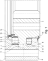
- the slewing bearing 1 can comprise two races 2 and 3, one of which forms an inner ring and the other race 3 forms an outer ring.
- the inner ring 2 mentioned can have a smaller inner diameter than the outer ring 3 and/or the outer ring 3 can have a larger outer diameter than the inner ring 2 mentioned.
- one race 2 for example the outer ring
- the groove mentioned can encompass the nose ring 5 from three sides, namely on two opposite end face sides and one lateral surface side.
- one race 2 can be supported relative to the other race 3 by three bearings, for example two axial bearings 8 and 9 and a radial bearing 11, said axial and radial bearings 8, 9 and 11 being in the groove between said nose ring 5 and the groove 4 mentioned can be arranged.
- the axial bearings 8, 9 and the radial bearing 11 can each be designed as cylindrical roller bearings, whereby the radial bearing 11 can have smaller rolling elements than the two axial bearings 8 and 9.
- the two axial bearings 8 and 9 can in turn have differently sized rolling elements, depending on the situation which direction stronger axial forces act.
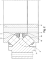
- One race 2 for example the inner ring, can have an open groove 4 towards the other race 3, for example towards the outer ring, into which the other race 3 engages with a nose ring 5 provided thereon, forming a gap or with a distance on all sides.
- the groove 4 mentioned can advantageously encompass the nose ring 5 from four sides, namely on two opposite lateral surface sides and on two opposite end surface sides of the mentioned nose ring 5.
- the race ring 2 having the groove 4 can be composed of a support ring 6 and a retaining ring 7 that can be placed thereon, cf. Fig. 1 .
- the nose ring 5 mentioned can also be supported relative to the groove 4 by three axial bearings 8, 9 and 10 and by two radial bearings 11 and 12, as shown Fig. 3 shows.
- two of the axial bearings 8 and 9 mentioned can be mounted on the same - according to Fig. 3 the lower nose ring end face and the third thrust bearing 10 can be arranged on the opposite nose ring end face.
- the radial bearings 11 and 12 can also be arranged on opposite sides, namely opposite lateral surface sides of the nose ring 5 mentioned, so that the nose ring 5 is sandwich-like embedded or supported both in the axial direction and in the radial direction between bearings located on opposite sides.
- the nose ring 5 is supported on all sides on the groove 4.
- the two thrust bearings 8 and 9 provided on the same nose ring end face can not only be spaced apart from one another in the radial direction and arranged on different raceways, but also in axial direction - ie in the direction of arrow 13 - be arranged offset from one another, so that the two axial bearings 8 and 9 are not at the same height.
- the two radial bearings 11 and 12 can be arranged opposite one another. Regardless of this, it can be advantageous if the two radial bearings 11 and 12 are arranged between the axial bearings 8, 9 and 10, cf. Fig. 3 .
- the two radial bearings 11 and 12 can have different rolling body geometries, whereby in particular one of the radial bearings 11 can be designed as a cylindrical roller bearing and the other radial bearing 12 can be designed as a ball bearing.
- At least one raceway of at least one row of bearings can have a longitudinal groove-like lubricant pocket 16 in a central section of the raceway, advantageously in each of the two opposite raceways of the respective row of bearings
- a lubricant pocket 16 can be provided, which extends along the row of rolling elements in the manner of a longitudinal groove, cf. Fig. 4 .
- a lubricant pocket can also be omitted, cf. Fig. 1 and 2 .
- middle sections 17 and 18 of the raceways 19 and 20 can be provided with a longitudinal groove-like recess, which forms a lubricant pocket 21 or 22 and is preferably completely filled with solid lubricant 15.
- raceway sections 19a, b and 20a, b which carry the rolling elements 23.
- the mentioned lubricant pocket 21 or 22, viewed in cross section, can have an approximately crescent-shaped contour, which can have a maximum depth centrally in the middle and tapers increasingly flatter towards the sides and / or forms sickle tips.
- the laterally adjoining raceway sections 19a, b and 20a, b can each be contoured in the shape of a half-shell or four-shell or, depending on the design of the bearing, generally have a shell-shaped contour and nestle against the spherical rolling elements, with a corresponding design also being possible with barrel-shaped rolling elements is.
- the lubricant pocket mentioned can also be provided for other rolling body shapes, for example cylindrical rollers or tapered rollers.
- the bearing gap 14 can also be filled with the solid lubricant 15 in side sections to the right and left of the row of rolling elements, cf. Fig. 1 and 2 , wherein the bearing gap 14 mentioned can advantageously also be completely filled there, in particular in such a way that the solid lubricant 15 forms a bridge between the bearing rings 2 and 3 and connects them to one another and / or seals the bearing gap 14 from the outside.
- the mentioned lateral bearing gap sections on the side next to the rolling elements can be filled with solid lubricant 15 essentially over the entire width of the bearing gap 14.
- bearing gap sections between adjacent rolling elements 23 of a row of rolling elements can also be filled with solid lubricant 15, so that the solid lubricant 15 provided between adjacent rolling elements So to speak, spacers form between the rolling elements 23, which keep the rolling elements at a distance from one another.
- the bearing gap sections mentioned between the rolling elements 23 of a row of rolling elements can be with the in Fig. 4 shown lateral bearing gap sections 14r and 14l, so that the solid lubricant 15 forms a cage of solid lubricant 15 surrounding the rolling bodies 23, which rotates together with the rolling bodies 23 relative to the two races 2 and 3.
- This cage-like spacer structure made of solid lubricant 15 includes in particular the two rings of solid lubricant - viewed in the cross section of a bearing - extending to the right and left of a respective row of rolling bodies on the right and left of the rolling bodies 23, which rings made of solid lubricant are connected to one another in a bridge-like manner between the rolling bodies, namely also by solid lubricant, which extends in the cavities between adjacent rolling elements 23.
Landscapes
- Engineering & Computer Science (AREA)
- General Engineering & Computer Science (AREA)
- Mechanical Engineering (AREA)
- Rolling Contact Bearings (AREA)
Claims (14)
- Palier à roulement de grande dimension, notamment palier à roulement de grande dimension sans centre (1), avec deux bagues de roulement concentriques (2, 3), entre lesquelles sont prévus, dans un interstice de palier (14), une pluralité de corps de roulement (23), qui sont agencés en plusieurs rangées de paliers, et qui roulent chacun sur au moins deux chemins de roulement (19, 20), les plusieurs rangées de paliers dans l'interstice de palier (14) comprenant au moins une rangée de paliers axiaux (8, 9) pour soutenir les bagues de roulement concentriques (2, 3) dans la direction axiale et au moins une rangée de paliers radiaux (11) pour soutenir les deux bagues de roulement (2, 3) dans la direction radiale, caractérisé en ce que la totalité de l'interstice de palier (14) entre les bagues de roulement (2, 3), dans lequel l'au moins une rangée de paliers axiaux (8, 9) et l'au moins une rangée de paliers radiaux (11) sont agencées, est entièrement rempli d'un lubrifiant solide (15), qui comprend une matrice polymère et un lubrifiant qui y est incorporé, le lubrifiant solide (15) assurant l'étanchéité vers l'extérieur de l'interstice de palier (14) par rapport aux corps de roulement (23) et l'interstice de palier (14) étant réalisé exempt de joints d'étanchéité séparés du lubrifiant solide (15).
- Palier à roulement de grande dimension selon la revendication précédente, dans lequel au moins l'un des chemins de roulement (19, 20) présente, dans une section centrale (17, 18), une poche de lubrifiant (21, 22) en forme de rainure longitudinale, qui est entièrement remplie du lubrifiant solide (15) et qui est flanquée des deux côtés de sections de chemin de roulement (19a, b ; 20a, b) qui portent les corps de roulement (23).
- Palier à roulement de grande dimension selon la revendication précédente, dans lequel les sections de chemin de roulement (19a, b ; 20a, b) situées des deux côtés s'adaptent chacune en forme de coque aux corps de roulement (23) en forme de bille ou de tonneau et la poche de lubrifiant (21, 22) forme, considérée en coupe transversale, un bombement approximativement en forme de demi-lune entre lesdites sections de chemin de roulement, qui est rempli de lubrifiant solide (15).
- Palier à roulement de grande dimension selon l'une quelconque des revendications précédentes, dans lequel le lubrifiant solide (15) forme, dans les espaces intermédiaires entre des corps de roulement (23) voisins de la même rangée de corps de roulement, des écarteurs entre les corps de roulement (23) de la rangée de corps de roulement, qui maintiennent les corps de roulement (23) espacés les uns des autres.
- Palier à roulement de grande dimension selon l'une quelconque des revendications précédentes, dans lequel le lubrifiant solide (15) forme dans l'interstice de palier (14) une structure d'écartement en forme de cage qui tourne conjointement avec les corps de roulement (23) par rapport aux deux bagues de palier.
- Palier à roulement de grande dimension selon la revendication précédente, dans lequel la structure d'écartement en forme de cage comprend, d'une part, des éléments d'écartement formés par le lubrifiant solide (15) entre des corps de roulement (23) voisins d'une rangée de corps de roulement et, d'autre part, des éléments de liaison formés par le lubrifiant solide (15), qui relient lesdits éléments d'écartement entre eux.
- Palier à roulement de grande dimension selon l'une quelconque des deux revendications précédentes, dans lequel la structure d'écartement est formée exclusivement par le lubrifiant solide (15).
- Palier à roulement de grande dimension selon l'une quelconque des revendications précédentes, dans lequel la matrice polymère du lubrifiant solide (15) est constituée d'un polyéthylène de poids moléculaire élevé, de préférence de poids moléculaire ultra-élevé.
- Palier à roulement de grande dimension selon l'une quelconque des revendications précédentes, dans lequel la matrice polymère du lubrifiant solide (15) forme une matrice poreuse, comprenant une pluralité d'évidements de petit volume, notamment approximativement de type éponge, et forme ainsi une structure de matrice de forme stable, mais déformable et/ou compressible, notamment ductile.
- Palier à roulement de grande dimension selon l'une quelconque des revendications précédentes, dans lequel le lubrifiant incorporé dans la matrice polymère est une huile de préférence synthétique, qui présente de préférence une viscosité dans la plage d'environ 75 à 200 mm2/s et/ou une viscosité dans la plage de 10 à 25 mm2/s à 100 °C.
- Palier à roulement de grande dimension selon l'une quelconque des revendications précédentes, dans lequel le lubrifiant incorporé dans la matrice polymère présente une proportion de plus de 50 % en masse ou plus de 50 pour cent en volume par rapport à la masse totale ou au volume total du lubrifiant solide, et/ou la matrice polymère présente une proportion de 20 à 40 % en masse ou pour cent en volume.
- Palier à roulement de grande dimension selon l'une quelconque des revendications précédentes, dans lequel un diamètre du palier à roulement de grande dimension défini par une rangée de corps de roulement la plus extérieure ou la plus intérieure est supérieur à 750 mm ou supérieur à 1 000 mm ou supérieur à 2 000 mm.
- Palier à roulement de grande dimension selon l'une quelconque des revendications précédentes, dans lequel les chemins de roulement (19, 20) des bagues de roulement (2, 3) sont durcis sur la couche de bord, notamment durcis par induction, et présentent une dureté supérieure à 52 HRC ou supérieure à 56 HRC ou supérieure à 57 HRC ou supérieure à 58 HRC ou supérieure à 59 HRC.
- Palier à roulement de grande dimension selon l'une quelconque des revendications précédentes, dans lequel au moins l'une des bagues de roulement présente des moyens de raccordement pour le raccordement d'une construction de raccordement, notamment des moyens de liaison à boulon fileté, et l'une des bagues de roulement (2, 3) est pourvue d'une denture ou est reliée de manière solidaire en rotation.
Applications Claiming Priority (2)
| Application Number | Priority Date | Filing Date | Title |
|---|---|---|---|
| DE202018102121.4U DE202018102121U1 (de) | 2018-04-17 | 2018-04-17 | Großwälzlager |
| PCT/EP2019/058887 WO2019201662A1 (fr) | 2018-04-17 | 2019-04-09 | Palier à roulement de grande dimension |
Publications (2)
| Publication Number | Publication Date |
|---|---|
| EP3759367A1 EP3759367A1 (fr) | 2021-01-06 |
| EP3759367B1 true EP3759367B1 (fr) | 2023-11-15 |
Family
ID=66240070
Family Applications (1)
| Application Number | Title | Priority Date | Filing Date |
|---|---|---|---|
| EP19718605.9A Active EP3759367B1 (fr) | 2018-04-17 | 2019-04-09 | Palier à roulement de grande dimension |
Country Status (7)
| Country | Link |
|---|---|
| US (1) | US11808301B2 (fr) |
| EP (1) | EP3759367B1 (fr) |
| CN (1) | CN112703328A (fr) |
| DE (1) | DE202018102121U1 (fr) |
| DK (1) | DK3759367T3 (fr) |
| ES (1) | ES2971792T3 (fr) |
| WO (1) | WO2019201662A1 (fr) |
Families Citing this family (6)
| Publication number | Priority date | Publication date | Assignee | Title |
|---|---|---|---|---|
| DE202018102121U1 (de) | 2018-04-17 | 2019-07-19 | Liebherr-Components Biberach Gmbh | Großwälzlager |
| CN110762124B (zh) * | 2019-10-30 | 2021-04-09 | 许昌许继风电科技有限公司 | 风力发电机的风轮及其变桨轴承 |
| DE102019217085A1 (de) * | 2019-11-06 | 2021-05-06 | Aktiebolaget Skf | Lager mit zumindest einem segmentierten Ring und Zusammenbauplatten |
| DE102020131634A1 (de) | 2020-11-30 | 2022-06-02 | Liebherr-Components Biberach Gmbh | Wälzlager sowie Zwischenstück hierfür |
| DE102021102133A1 (de) * | 2021-01-29 | 2022-08-04 | Aktiebolaget Skf | Wälzlager mit Führungsflansch für Käfig |
| CN114135576B (zh) * | 2021-12-13 | 2023-10-31 | 中国铁建重工集团股份有限公司 | 一种掘进机主轴承及该主轴承外圈组件的加工方法 |
Citations (4)
| Publication number | Priority date | Publication date | Assignee | Title |
|---|---|---|---|---|
| DE102010051968A1 (de) * | 2010-11-19 | 2012-05-24 | Schaeffler Technologies Gmbh & Co. Kg | Selbsttragender Wälzkörperring sowie Wälzlageranordnung |
| US20140197006A1 (en) * | 2013-01-16 | 2014-07-17 | Eugene Kverel | Roller structure with anti-friction bearings |
| EP2762737A1 (fr) * | 2013-01-31 | 2014-08-06 | Siemens Aktiengesellschaft | Roulement et procédé de collecte d'une fuite de lubrifiant d'un palier |
| DE202016003040U1 (de) * | 2016-04-28 | 2016-06-08 | Imo Holding Gmbh | Dichtung für eine Drehlagerung, sowie eine Windkraftanlage, deren Hauptlager mit einer derartigen Dichtung ausgerüstet ist |
Family Cites Families (30)
| Publication number | Priority date | Publication date | Assignee | Title |
|---|---|---|---|---|
| US1135177A (en) * | 1909-10-21 | 1915-04-13 | New Departure Mfg Co | Ball-bearing. |
| JPS60143244A (ja) * | 1983-12-29 | 1985-07-29 | Mitsubishi Electric Corp | ハ−モニツクギヤ装置 |
| JP3517268B2 (ja) * | 1994-03-14 | 2004-04-12 | Ntn株式会社 | 円筒ころ軸受 |
| JP3831507B2 (ja) * | 1998-01-14 | 2006-10-11 | 株式会社ジェイテクト | 軸受部材 |
| US6485184B1 (en) * | 1999-09-29 | 2002-11-26 | Koyo Seiko Co., Ltd. | Rolling bearing |
| JP2002212581A (ja) * | 2001-01-23 | 2002-07-31 | Koyo Seiko Co Ltd | 固形潤滑組成物およびポリマ潤滑剤封入転がり軸受 |
| JP2003042165A (ja) * | 2001-07-31 | 2003-02-13 | Ntn Corp | 転がり軸受及びその組立方法 |
| JP2003214446A (ja) * | 2002-01-22 | 2003-07-30 | Hitachi Constr Mach Co Ltd | 建設機械の旋回軸受 |
| JP2003222140A (ja) * | 2002-01-28 | 2003-08-08 | Hitachi Constr Mach Co Ltd | 軸受及び建設機械の旋回軸受 |
| JP4059092B2 (ja) * | 2003-01-31 | 2008-03-12 | 株式会社ジェイテクト | 転がり軸受の製造方法 |
| EP1719812B1 (fr) * | 2004-02-09 | 2018-04-04 | NTN Corporation | Graisse |
| JP2006022851A (ja) * | 2004-07-06 | 2006-01-26 | Hitachi Constr Mach Co Ltd | 建設機械の旋回軸受、及びその組立方法 |
| DE102006054453B4 (de) * | 2006-11-16 | 2016-10-20 | Rothe Erde Gmbh | Rollenlager, insbesondere mittenfreies Großwälzlager |
| US20080169257A1 (en) * | 2007-01-17 | 2008-07-17 | Itrec B.V. | Hoisting crane with annular bearing structure |
| DE202007002609U1 (de) * | 2007-02-19 | 2008-04-03 | Landwehr, Markus | Drehverbindung |
| JP2008215419A (ja) * | 2007-02-28 | 2008-09-18 | Ntn Corp | 転がり軸受 |
| WO2008146837A1 (fr) * | 2007-05-29 | 2008-12-04 | Ntn Corporation | Palier prélubrifié par lubrifiant solide en mousse et procédé de production de celui-ci |
| DE102007041549A1 (de) * | 2007-08-31 | 2009-03-05 | Schaeffler Kg | Wälzlager |
| DE102008049813A1 (de) * | 2008-09-30 | 2010-04-01 | Schaeffler Kg | Drehverbindung, zum Beispiel für eine Windenergieanlage sowie Windenergieanlage mit der Drehverbindung |
| DK2427666T3 (en) * | 2009-05-06 | 2017-10-16 | Skf Ab | BIG Roller Bearing |
| US10155914B2 (en) * | 2011-02-08 | 2018-12-18 | Eugene Kverel | Solid lubricant |
| JP5905681B2 (ja) * | 2011-08-23 | 2016-04-20 | Ntn株式会社 | 転がり軸受 |
| JP6102137B2 (ja) * | 2012-09-20 | 2017-03-29 | 株式会社ジェイテクト | 転がり軸受 |
| DE202013009246U1 (de) * | 2013-10-18 | 2015-02-19 | Liebherr-Components Biberach Gmbh | Wälzlager |
| DE102014104599B8 (de) * | 2014-04-01 | 2019-01-17 | Thyssenkrupp Ag | Wälzlager |
| EP3078869A1 (fr) * | 2015-04-09 | 2016-10-12 | ThyssenKrupp AG | Cage pour un palier à roulement multi-rangées et palier à roulement multi-rangées pour éoliennes |
| US10054156B2 (en) * | 2016-06-26 | 2018-08-21 | Atec Corporation | Synthetic resin retainer for large thrust ball bearings with dry-lubricant and wet-lubricant management systems |
| DE102016211690A1 (de) * | 2016-06-29 | 2018-01-04 | Aktiebolaget Skf | Fahrradwälzlagerung |
| DE202018102121U1 (de) | 2018-04-17 | 2019-07-19 | Liebherr-Components Biberach Gmbh | Großwälzlager |
| DE102018213357A1 (de) * | 2018-04-24 | 2019-10-24 | Aktiebolaget Skf | Schwenklager mit Dichtungsanordnung |
-
2018
- 2018-04-17 DE DE202018102121.4U patent/DE202018102121U1/de active Active
-
2019
- 2019-04-09 EP EP19718605.9A patent/EP3759367B1/fr active Active
- 2019-04-09 ES ES19718605T patent/ES2971792T3/es active Active
- 2019-04-09 DK DK19718605.9T patent/DK3759367T3/da active
- 2019-04-09 CN CN201980026711.7A patent/CN112703328A/zh active Pending
- 2019-04-09 WO PCT/EP2019/058887 patent/WO2019201662A1/fr unknown
-
2020
- 2020-10-14 US US17/070,434 patent/US11808301B2/en active Active
Patent Citations (4)
| Publication number | Priority date | Publication date | Assignee | Title |
|---|---|---|---|---|
| DE102010051968A1 (de) * | 2010-11-19 | 2012-05-24 | Schaeffler Technologies Gmbh & Co. Kg | Selbsttragender Wälzkörperring sowie Wälzlageranordnung |
| US20140197006A1 (en) * | 2013-01-16 | 2014-07-17 | Eugene Kverel | Roller structure with anti-friction bearings |
| EP2762737A1 (fr) * | 2013-01-31 | 2014-08-06 | Siemens Aktiengesellschaft | Roulement et procédé de collecte d'une fuite de lubrifiant d'un palier |
| DE202016003040U1 (de) * | 2016-04-28 | 2016-06-08 | Imo Holding Gmbh | Dichtung für eine Drehlagerung, sowie eine Windkraftanlage, deren Hauptlager mit einer derartigen Dichtung ausgerüstet ist |
Non-Patent Citations (2)
| Title |
|---|
| NTN: "NTN, Bearings with solid grease", 19 April 2022 (2022-04-19), -, XP055970542, Retrieved from the Internet <URL:-> [retrieved on 20220419] * |
| SKF: "SKF bearings with Solid Oil", 31 December 2016 (2016-12-31), XP055970528, Retrieved from the Internet <URL:-> [retrieved on 20220419] * |
Also Published As
| Publication number | Publication date |
|---|---|
| US20210102575A1 (en) | 2021-04-08 |
| DK3759367T3 (da) | 2023-12-11 |
| EP3759367A1 (fr) | 2021-01-06 |
| WO2019201662A1 (fr) | 2019-10-24 |
| DE202018102121U1 (de) | 2019-07-19 |
| CN112703328A (zh) | 2021-04-23 |
| US11808301B2 (en) | 2023-11-07 |
| ES2971792T3 (es) | 2024-06-07 |
Similar Documents
| Publication | Publication Date | Title |
|---|---|---|
| EP3759367B1 (fr) | Palier à roulement de grande dimension | |
| EP2561241B1 (fr) | Ensemble d'étanchéité pour palier à roulement | |
| EP2812591B1 (fr) | Ensemble destiné à supporter des pièces d'une installation de production d'énergie pouvant tourner les unes par rapport aux autres | |
| DE19962978C1 (de) | Windenergieanlage mit einem turmgestützten Maschinenkopf | |
| EP2092204B2 (fr) | Roulement, notamment roulement de grand gabarit sans centre | |
| EP2233760B1 (fr) | Palier à roulement à deux rangées lubrifié par de la graisse et système de stockage doté d'un tel palier à roulement et d'un dispositif de lubrification | |
| EP2715162B1 (fr) | Couronne d'orientation | |
| EP2729712B1 (fr) | Roulement à rotule sur rouleaux avec dispositif d'étanchéité et ailette de stabilisation avec le roulement à rotule sur rouleaux | |
| DE102007019482A1 (de) | Mehrreihiges Großwälzlager, insbesondere Axial-Radiallager zur Hauptlagerung der Rotorwelle einer Windkraftanlage | |
| WO2018189143A1 (fr) | Ensemble palier servant à supporter une pale de rotor d'une éolienne | |
| EP2507522B1 (fr) | Roulement à billes | |
| EP3721104B1 (fr) | Agencement de paliers a roulement | |
| DE102015112056B4 (de) | Wälzlageranordnung, insbesondere Großwälzlageranordnung, und Blattlager für eine Windkraftanlage | |
| EP3721106B1 (fr) | Palier a roulement a plusieurs rangées | |
| DE202008001286U1 (de) | Wälzlagerschmiervorrichtung | |
| DE102006059186A1 (de) | Einstelllager | |
| WO2021032843A1 (fr) | Palier de rotor pour une éolienne, et éolienne | |
| EP3947995B1 (fr) | Paliers à roulement de grande dimension | |
| WO2009006875A1 (fr) | Palier à roulement, en particulier palier à rouleaux | |
| WO2008068123A1 (fr) | Palier de soutien d'une transmission à embrayage double | |
| EP3721103B1 (fr) | Assemblage de paliers roulants | |
| DE102020116588A1 (de) | Schräggleitlager | |
| DE102014210155A1 (de) | Pendelrollenlager und Verfahren zur Montage eines Pendelrollenlagers | |
| DE102012204571A1 (de) | Wälzlager | |
| DE102010008945A1 (de) | Kegelrollenlager |
Legal Events
| Date | Code | Title | Description |
|---|---|---|---|
| STAA | Information on the status of an ep patent application or granted ep patent |
Free format text: STATUS: UNKNOWN |
|
| STAA | Information on the status of an ep patent application or granted ep patent |
Free format text: STATUS: THE INTERNATIONAL PUBLICATION HAS BEEN MADE |
|
| PUAI | Public reference made under article 153(3) epc to a published international application that has entered the european phase |
Free format text: ORIGINAL CODE: 0009012 |
|
| STAA | Information on the status of an ep patent application or granted ep patent |
Free format text: STATUS: REQUEST FOR EXAMINATION WAS MADE |
|
| 17P | Request for examination filed |
Effective date: 20200930 |
|
| AK | Designated contracting states |
Kind code of ref document: A1 Designated state(s): AL AT BE BG CH CY CZ DE DK EE ES FI FR GB GR HR HU IE IS IT LI LT LU LV MC MK MT NL NO PL PT RO RS SE SI SK SM TR |
|
| AX | Request for extension of the european patent |
Extension state: BA ME |
|
| STAA | Information on the status of an ep patent application or granted ep patent |
Free format text: STATUS: EXAMINATION IS IN PROGRESS |
|
| 17Q | First examination report despatched |
Effective date: 20210618 |
|
| DAV | Request for validation of the european patent (deleted) | ||
| DAX | Request for extension of the european patent (deleted) | ||
| TPAC | Observations filed by third parties |
Free format text: ORIGINAL CODE: EPIDOSNTIPA |
|
| REG | Reference to a national code |
Ref country code: DE Ref legal event code: R079 Ref document number: 502019009927 Country of ref document: DE Free format text: PREVIOUS MAIN CLASS: F16C0033660000 Ipc: F16C0019080000 Ref country code: DE Ref legal event code: R079 Free format text: PREVIOUS MAIN CLASS: F16C0033660000 Ipc: F16C0019080000 |
|
| RIC1 | Information provided on ipc code assigned before grant |
Ipc: F16C 19/56 20060101ALI20230426BHEP Ipc: F16C 19/38 20060101ALI20230426BHEP Ipc: F16C 19/28 20060101ALI20230426BHEP Ipc: F16C 19/18 20060101ALI20230426BHEP Ipc: F16C 19/08 20060101AFI20230426BHEP |
|
| GRAP | Despatch of communication of intention to grant a patent |
Free format text: ORIGINAL CODE: EPIDOSNIGR1 |
|
| STAA | Information on the status of an ep patent application or granted ep patent |
Free format text: STATUS: GRANT OF PATENT IS INTENDED |
|
| INTG | Intention to grant announced |
Effective date: 20230616 |
|
| GRAS | Grant fee paid |
Free format text: ORIGINAL CODE: EPIDOSNIGR3 |
|
| GRAA | (expected) grant |
Free format text: ORIGINAL CODE: 0009210 |
|
| STAA | Information on the status of an ep patent application or granted ep patent |
Free format text: STATUS: THE PATENT HAS BEEN GRANTED |
|
| AK | Designated contracting states |
Kind code of ref document: B1 Designated state(s): AL AT BE BG CH CY CZ DE DK EE ES FI FR GB GR HR HU IE IS IT LI LT LU LV MC MK MT NL NO PL PT RO RS SE SI SK SM TR |
|
| REG | Reference to a national code |
Ref country code: CH Ref legal event code: EP Ref country code: GB Ref legal event code: FG4D Free format text: NOT ENGLISH |
|
| REG | Reference to a national code |
Ref country code: DE Ref legal event code: R096 Ref document number: 502019009927 Country of ref document: DE |
|
| P01 | Opt-out of the competence of the unified patent court (upc) registered |
Effective date: 20231031 |
|
| REG | Reference to a national code |
Ref country code: IE Ref legal event code: FG4D Free format text: LANGUAGE OF EP DOCUMENT: GERMAN |
|
| REG | Reference to a national code |
Ref country code: DK Ref legal event code: T3 Effective date: 20231205 |
|
| REG | Reference to a national code |
Ref country code: LT Ref legal event code: MG9D |
|
| REG | Reference to a national code |
Ref country code: NL Ref legal event code: MP Effective date: 20231115 |
|
| PG25 | Lapsed in a contracting state [announced via postgrant information from national office to epo] |
Ref country code: GR Free format text: LAPSE BECAUSE OF FAILURE TO SUBMIT A TRANSLATION OF THE DESCRIPTION OR TO PAY THE FEE WITHIN THE PRESCRIBED TIME-LIMIT Effective date: 20240216 |
|
| PG25 | Lapsed in a contracting state [announced via postgrant information from national office to epo] |
Ref country code: IS Free format text: LAPSE BECAUSE OF FAILURE TO SUBMIT A TRANSLATION OF THE DESCRIPTION OR TO PAY THE FEE WITHIN THE PRESCRIBED TIME-LIMIT Effective date: 20240315 |
|
| PG25 | Lapsed in a contracting state [announced via postgrant information from national office to epo] |
Ref country code: LT Free format text: LAPSE BECAUSE OF FAILURE TO SUBMIT A TRANSLATION OF THE DESCRIPTION OR TO PAY THE FEE WITHIN THE PRESCRIBED TIME-LIMIT Effective date: 20231115 |
|
| PG25 | Lapsed in a contracting state [announced via postgrant information from national office to epo] |
Ref country code: NL Free format text: LAPSE BECAUSE OF FAILURE TO SUBMIT A TRANSLATION OF THE DESCRIPTION OR TO PAY THE FEE WITHIN THE PRESCRIBED TIME-LIMIT Effective date: 20231115 |
|
| PG25 | Lapsed in a contracting state [announced via postgrant information from national office to epo] |
Ref country code: NL Free format text: LAPSE BECAUSE OF FAILURE TO SUBMIT A TRANSLATION OF THE DESCRIPTION OR TO PAY THE FEE WITHIN THE PRESCRIBED TIME-LIMIT Effective date: 20231115 Ref country code: LT Free format text: LAPSE BECAUSE OF FAILURE TO SUBMIT A TRANSLATION OF THE DESCRIPTION OR TO PAY THE FEE WITHIN THE PRESCRIBED TIME-LIMIT Effective date: 20231115 Ref country code: IS Free format text: LAPSE BECAUSE OF FAILURE TO SUBMIT A TRANSLATION OF THE DESCRIPTION OR TO PAY THE FEE WITHIN THE PRESCRIBED TIME-LIMIT Effective date: 20240315 Ref country code: GR Free format text: LAPSE BECAUSE OF FAILURE TO SUBMIT A TRANSLATION OF THE DESCRIPTION OR TO PAY THE FEE WITHIN THE PRESCRIBED TIME-LIMIT Effective date: 20240216 Ref country code: BG Free format text: LAPSE BECAUSE OF FAILURE TO SUBMIT A TRANSLATION OF THE DESCRIPTION OR TO PAY THE FEE WITHIN THE PRESCRIBED TIME-LIMIT Effective date: 20240215 Ref country code: PT Free format text: LAPSE BECAUSE OF FAILURE TO SUBMIT A TRANSLATION OF THE DESCRIPTION OR TO PAY THE FEE WITHIN THE PRESCRIBED TIME-LIMIT Effective date: 20240315 |
|
| PG25 | Lapsed in a contracting state [announced via postgrant information from national office to epo] |
Ref country code: SE Free format text: LAPSE BECAUSE OF FAILURE TO SUBMIT A TRANSLATION OF THE DESCRIPTION OR TO PAY THE FEE WITHIN THE PRESCRIBED TIME-LIMIT Effective date: 20231115 Ref country code: RS Free format text: LAPSE BECAUSE OF FAILURE TO SUBMIT A TRANSLATION OF THE DESCRIPTION OR TO PAY THE FEE WITHIN THE PRESCRIBED TIME-LIMIT Effective date: 20231115 Ref country code: PL Free format text: LAPSE BECAUSE OF FAILURE TO SUBMIT A TRANSLATION OF THE DESCRIPTION OR TO PAY THE FEE WITHIN THE PRESCRIBED TIME-LIMIT Effective date: 20231115 Ref country code: NO Free format text: LAPSE BECAUSE OF FAILURE TO SUBMIT A TRANSLATION OF THE DESCRIPTION OR TO PAY THE FEE WITHIN THE PRESCRIBED TIME-LIMIT Effective date: 20240215 Ref country code: LV Free format text: LAPSE BECAUSE OF FAILURE TO SUBMIT A TRANSLATION OF THE DESCRIPTION OR TO PAY THE FEE WITHIN THE PRESCRIBED TIME-LIMIT Effective date: 20231115 Ref country code: HR Free format text: LAPSE BECAUSE OF FAILURE TO SUBMIT A TRANSLATION OF THE DESCRIPTION OR TO PAY THE FEE WITHIN THE PRESCRIBED TIME-LIMIT Effective date: 20231115 |
|
| REG | Reference to a national code |
Ref country code: ES Ref legal event code: FG2A Ref document number: 2971792 Country of ref document: ES Kind code of ref document: T3 Effective date: 20240607 |
|
| PGFP | Annual fee paid to national office [announced via postgrant information from national office to epo] |
Ref country code: GB Payment date: 20240423 Year of fee payment: 6 |
|
| PGFP | Annual fee paid to national office [announced via postgrant information from national office to epo] |
Ref country code: DE Payment date: 20240425 Year of fee payment: 6 |
|
| PGFP | Annual fee paid to national office [announced via postgrant information from national office to epo] |
Ref country code: DK Payment date: 20240423 Year of fee payment: 6 |
|
| PGFP | Annual fee paid to national office [announced via postgrant information from national office to epo] |
Ref country code: ES Payment date: 20240503 Year of fee payment: 6 |
|
| PG25 | Lapsed in a contracting state [announced via postgrant information from national office to epo] |
Ref country code: CZ Free format text: LAPSE BECAUSE OF FAILURE TO SUBMIT A TRANSLATION OF THE DESCRIPTION OR TO PAY THE FEE WITHIN THE PRESCRIBED TIME-LIMIT Effective date: 20231115 |
|
| PG25 | Lapsed in a contracting state [announced via postgrant information from national office to epo] |
Ref country code: SK Free format text: LAPSE BECAUSE OF FAILURE TO SUBMIT A TRANSLATION OF THE DESCRIPTION OR TO PAY THE FEE WITHIN THE PRESCRIBED TIME-LIMIT Effective date: 20231115 |
|
| PG25 | Lapsed in a contracting state [announced via postgrant information from national office to epo] |
Ref country code: SM Free format text: LAPSE BECAUSE OF FAILURE TO SUBMIT A TRANSLATION OF THE DESCRIPTION OR TO PAY THE FEE WITHIN THE PRESCRIBED TIME-LIMIT Effective date: 20231115 Ref country code: SK Free format text: LAPSE BECAUSE OF FAILURE TO SUBMIT A TRANSLATION OF THE DESCRIPTION OR TO PAY THE FEE WITHIN THE PRESCRIBED TIME-LIMIT Effective date: 20231115 Ref country code: RO Free format text: LAPSE BECAUSE OF FAILURE TO SUBMIT A TRANSLATION OF THE DESCRIPTION OR TO PAY THE FEE WITHIN THE PRESCRIBED TIME-LIMIT Effective date: 20231115 Ref country code: IT Free format text: LAPSE BECAUSE OF FAILURE TO SUBMIT A TRANSLATION OF THE DESCRIPTION OR TO PAY THE FEE WITHIN THE PRESCRIBED TIME-LIMIT Effective date: 20231115 Ref country code: EE Free format text: LAPSE BECAUSE OF FAILURE TO SUBMIT A TRANSLATION OF THE DESCRIPTION OR TO PAY THE FEE WITHIN THE PRESCRIBED TIME-LIMIT Effective date: 20231115 Ref country code: CZ Free format text: LAPSE BECAUSE OF FAILURE TO SUBMIT A TRANSLATION OF THE DESCRIPTION OR TO PAY THE FEE WITHIN THE PRESCRIBED TIME-LIMIT Effective date: 20231115 |
|
| PGFP | Annual fee paid to national office [announced via postgrant information from national office to epo] |
Ref country code: FR Payment date: 20240423 Year of fee payment: 6 |