EP2715162B1 - Couronne d'orientation - Google Patents
Couronne d'orientation Download PDFInfo
- Publication number
- EP2715162B1 EP2715162B1 EP12722732.0A EP12722732A EP2715162B1 EP 2715162 B1 EP2715162 B1 EP 2715162B1 EP 12722732 A EP12722732 A EP 12722732A EP 2715162 B1 EP2715162 B1 EP 2715162B1
- Authority
- EP
- European Patent Office
- Prior art keywords
- ball
- shoulder
- diameter
- row
- roller bearing
- Prior art date
- Legal status (The legal status is an assumption and is not a legal conclusion. Google has not performed a legal analysis and makes no representation as to the accuracy of the status listed.)
- Active
Links
Images


Classifications
-
- F—MECHANICAL ENGINEERING; LIGHTING; HEATING; WEAPONS; BLASTING
- F16—ENGINEERING ELEMENTS AND UNITS; GENERAL MEASURES FOR PRODUCING AND MAINTAINING EFFECTIVE FUNCTIONING OF MACHINES OR INSTALLATIONS; THERMAL INSULATION IN GENERAL
- F16C—SHAFTS; FLEXIBLE SHAFTS; ELEMENTS OR CRANKSHAFT MECHANISMS; ROTARY BODIES OTHER THAN GEARING ELEMENTS; BEARINGS
- F16C19/00—Bearings with rolling contact, for exclusively rotary movement
- F16C19/02—Bearings with rolling contact, for exclusively rotary movement with bearing balls essentially of the same size in one or more circular rows
- F16C19/04—Bearings with rolling contact, for exclusively rotary movement with bearing balls essentially of the same size in one or more circular rows for radial load mainly
- F16C19/08—Bearings with rolling contact, for exclusively rotary movement with bearing balls essentially of the same size in one or more circular rows for radial load mainly with two or more rows of balls
-
- F—MECHANICAL ENGINEERING; LIGHTING; HEATING; WEAPONS; BLASTING
- F16—ENGINEERING ELEMENTS AND UNITS; GENERAL MEASURES FOR PRODUCING AND MAINTAINING EFFECTIVE FUNCTIONING OF MACHINES OR INSTALLATIONS; THERMAL INSULATION IN GENERAL
- F16C—SHAFTS; FLEXIBLE SHAFTS; ELEMENTS OR CRANKSHAFT MECHANISMS; ROTARY BODIES OTHER THAN GEARING ELEMENTS; BEARINGS
- F16C33/00—Parts of bearings; Special methods for making bearings or parts thereof
- F16C33/30—Parts of ball or roller bearings
- F16C33/58—Raceways; Race rings
-
- F—MECHANICAL ENGINEERING; LIGHTING; HEATING; WEAPONS; BLASTING
- F03—MACHINES OR ENGINES FOR LIQUIDS; WIND, SPRING, OR WEIGHT MOTORS; PRODUCING MECHANICAL POWER OR A REACTIVE PROPULSIVE THRUST, NOT OTHERWISE PROVIDED FOR
- F03D—WIND MOTORS
- F03D80/00—Details, components or accessories not provided for in groups F03D1/00 - F03D17/00
- F03D80/70—Bearing or lubricating arrangements
-
- F—MECHANICAL ENGINEERING; LIGHTING; HEATING; WEAPONS; BLASTING
- F16—ENGINEERING ELEMENTS AND UNITS; GENERAL MEASURES FOR PRODUCING AND MAINTAINING EFFECTIVE FUNCTIONING OF MACHINES OR INSTALLATIONS; THERMAL INSULATION IN GENERAL
- F16C—SHAFTS; FLEXIBLE SHAFTS; ELEMENTS OR CRANKSHAFT MECHANISMS; ROTARY BODIES OTHER THAN GEARING ELEMENTS; BEARINGS
- F16C19/00—Bearings with rolling contact, for exclusively rotary movement
- F16C19/02—Bearings with rolling contact, for exclusively rotary movement with bearing balls essentially of the same size in one or more circular rows
- F16C19/14—Bearings with rolling contact, for exclusively rotary movement with bearing balls essentially of the same size in one or more circular rows for both radial and axial load
- F16C19/18—Bearings with rolling contact, for exclusively rotary movement with bearing balls essentially of the same size in one or more circular rows for both radial and axial load with two or more rows of balls
- F16C19/181—Bearings with rolling contact, for exclusively rotary movement with bearing balls essentially of the same size in one or more circular rows for both radial and axial load with two or more rows of balls with angular contact
-
- F—MECHANICAL ENGINEERING; LIGHTING; HEATING; WEAPONS; BLASTING
- F16—ENGINEERING ELEMENTS AND UNITS; GENERAL MEASURES FOR PRODUCING AND MAINTAINING EFFECTIVE FUNCTIONING OF MACHINES OR INSTALLATIONS; THERMAL INSULATION IN GENERAL
- F16C—SHAFTS; FLEXIBLE SHAFTS; ELEMENTS OR CRANKSHAFT MECHANISMS; ROTARY BODIES OTHER THAN GEARING ELEMENTS; BEARINGS
- F16C33/00—Parts of bearings; Special methods for making bearings or parts thereof
- F16C33/30—Parts of ball or roller bearings
- F16C33/58—Raceways; Race rings
- F16C33/583—Details of specific parts of races
-
- F—MECHANICAL ENGINEERING; LIGHTING; HEATING; WEAPONS; BLASTING
- F16—ENGINEERING ELEMENTS AND UNITS; GENERAL MEASURES FOR PRODUCING AND MAINTAINING EFFECTIVE FUNCTIONING OF MACHINES OR INSTALLATIONS; THERMAL INSULATION IN GENERAL
- F16C—SHAFTS; FLEXIBLE SHAFTS; ELEMENTS OR CRANKSHAFT MECHANISMS; ROTARY BODIES OTHER THAN GEARING ELEMENTS; BEARINGS
- F16C33/00—Parts of bearings; Special methods for making bearings or parts thereof
- F16C33/30—Parts of ball or roller bearings
- F16C33/58—Raceways; Race rings
- F16C33/60—Raceways; Race rings divided or split, e.g. comprising two juxtaposed rings
-
- F—MECHANICAL ENGINEERING; LIGHTING; HEATING; WEAPONS; BLASTING
- F16—ENGINEERING ELEMENTS AND UNITS; GENERAL MEASURES FOR PRODUCING AND MAINTAINING EFFECTIVE FUNCTIONING OF MACHINES OR INSTALLATIONS; THERMAL INSULATION IN GENERAL
- F16C—SHAFTS; FLEXIBLE SHAFTS; ELEMENTS OR CRANKSHAFT MECHANISMS; ROTARY BODIES OTHER THAN GEARING ELEMENTS; BEARINGS
- F16C2300/00—Application independent of particular apparatuses
- F16C2300/10—Application independent of particular apparatuses related to size
- F16C2300/14—Large applications, e.g. bearings having an inner diameter exceeding 500 mm
-
- F—MECHANICAL ENGINEERING; LIGHTING; HEATING; WEAPONS; BLASTING
- F16—ENGINEERING ELEMENTS AND UNITS; GENERAL MEASURES FOR PRODUCING AND MAINTAINING EFFECTIVE FUNCTIONING OF MACHINES OR INSTALLATIONS; THERMAL INSULATION IN GENERAL
- F16C—SHAFTS; FLEXIBLE SHAFTS; ELEMENTS OR CRANKSHAFT MECHANISMS; ROTARY BODIES OTHER THAN GEARING ELEMENTS; BEARINGS
- F16C2360/00—Engines or pumps
- F16C2360/31—Wind motors
-
- Y—GENERAL TAGGING OF NEW TECHNOLOGICAL DEVELOPMENTS; GENERAL TAGGING OF CROSS-SECTIONAL TECHNOLOGIES SPANNING OVER SEVERAL SECTIONS OF THE IPC; TECHNICAL SUBJECTS COVERED BY FORMER USPC CROSS-REFERENCE ART COLLECTIONS [XRACs] AND DIGESTS
- Y02—TECHNOLOGIES OR APPLICATIONS FOR MITIGATION OR ADAPTATION AGAINST CLIMATE CHANGE
- Y02E—REDUCTION OF GREENHOUSE GAS [GHG] EMISSIONS, RELATED TO ENERGY GENERATION, TRANSMISSION OR DISTRIBUTION
- Y02E10/00—Energy generation through renewable energy sources
- Y02E10/70—Wind energy
- Y02E10/72—Wind turbines with rotation axis in wind direction
Definitions
- the present invention relates to a slewing bearing, which is designed as a multi-row ball slewing for receiving axial loads, radial loads and tilting moments, with an outer ring, an inner ring, a first row of balls and a second row of balls, wherein the first row of balls and the second row of balls axially spaced from each other in a four-point bearing are arranged, wherein the first ball row four track sections and the second ball row four track sections are assigned, each having a surface for receiving the ball track.
- the present invention was based on the object to provide a slewing bearing of the type mentioned with improved load bearing with the smallest possible installation dimensions.
- the invention solves the underlying task in a large roller bearing of the type mentioned by the surface of each one provided in the inner raceway section is greater than the surface of each adjacent raceway section provided in the inner ring and equal to the surface of each diametrically opposite in the Outer ring provided raceway section is.
- the invention is based on the recognition that the ball row of a four-point bearing has a total of four contact points, each with separate surface sections in the inner and outer ring. These points of contact are not constant at the same point - relative to the cross section of the bearing - but change depending on the load situation. This also applies to the case of load reversals.
- the invention makes use of the fact that, when designing the bearing, it is already known in which direction - viewed axially - the load on the bearing will be greater.
- the bearing can therefore be specifically adapted to receive higher loads from one axial direction than from the other direction.
- the invention uses the knowledge about the displacement of the contact area within the raceway surfaces by the expected more heavily loaded areas are increased compared to the expected less loaded areas , The additional space required as a result of an increase in area can be compensated in this way by reducing the respective corresponding, less loaded area corresponding to the enlargement of the one area.
- the invention is advantageously further developed in that the surface of the raceway section provided in the inner ring is equal to the surface of the respectively diametrically opposite raceway section provided for the outer ring.
- the respective larger surfaces of the raceway sections are the same size. Under the same size surfaces is understood here that taking into account manufacturing tolerances, the length of a raceway surface in cross section should not change by more than +/- 3%.
- cross-sectional area is generally meant, not the actual circumferential area.
- the inner ring for the first row of balls on an annular first inner shoulder and an annular second inner shoulder, each defining one of the surfaces for receiving a ball raceway of the first row of balls.
- the inner ring for the second ball row on an annular third inner shoulder and an annular fourth inner shoulder, each defining one of the surfaces for receiving the ball track of the second row of balls, wherein a maximum diameter of the fourth inner shoulder is different from a maximum diameter of the first inner shoulder.
- the maximum diameter of the third inner shoulder is different from the maximum diameter of the second inner shoulder.
- the outer ring additionally has, for the second row of balls, a third annular outer shoulder and a fourth annular outer shoulder each defining one of the surfaces for receiving the ball races of the second row of balls, the minimum diameter of the fourth outer shoulder being different from the minimum diameter of the first outer shoulder.
- the outer race and raceway portions provided in the outer race are preferably configured corresponding to the respective portions of the inner race to equally compensate for a symmetrical displacement of the contact area between the balls and the raceway area surfaces in both the inner race and the outer race.
- the minimum diameter of the third outer shoulder is different from the minimum diameter of the second outer shoulder.
- the largest of the maximum diameters of the inner shoulders is less than or equal to the smallest of the minimum diameters of the outer shoulders.
- the balls of the first row of balls are arranged in a preferred embodiment, together with the balls of the second row of balls along a first circle diameter.
- the largest of the maximum diameters of the inner shoulders and / or the smallest of the minimum diameters of the outer shoulders is equal to or in a range of up to 0.5 mm below the first pitch diameter of the first and second ball rows.
- the lowest of the minimum outer shoulder diameters is equal to or within a range of up to 0.5 mm above the first first and second ball raceway diameters.
- the maximum diameter of the first inner shoulder is equal to the maximum diameter of the third inner shoulder and greater than the maximum diameter of the respective second and fourth inner shoulder.
- the minimum diameter of the second outer shoulder is equal to the minimum diameter of the fourth outer shoulder and less than the minimum diameter of the respective first and third outer shoulder.
- the balls of the first ball row are arranged along the first pitch diameter, and the balls of the second ball row are arranged along a second pitch diameter, which is different from the diameter of the first ball row.
- the maximum diameter of the first inner shoulder is greater than the maximum diameter of the second inner shoulder and the maximum diameter of the third inner shoulder greater than the maximum diameter of the fourth inner shoulder.
- the minimum diameter of the fourth outer shoulder is less than the minimum diameter of the third outer shoulder, and the minimum diameter the second outer shoulder is less than the minimum diameter of the first inner shoulder.
- the first ball row consists of balls with a first ball diameter and the second ball row consists of balls with a second ball diameter, which is different from the first ball diameter.
- the large rolling bearing on one or more other rows of balls are preferably formed according to the first row of balls and / or the second row of balls according to the preferred embodiments explained above. This relates in particular to the design of opposite shoulders, raceway sections, ball diameter and / or diameter. According to a particularly preferred embodiment, the large rolling bearing on a third row of balls.
- the invention further relates to a wind energy plant with a tower having a tower head and a nacelle, which is adapted to receive a rotor, wherein the nacelle is rotatably supported by means of an azimuth bearing relative to the tower.
- the aforementioned wind turbine is inventively improved by the fact that the azimuth bearing is described as a large rolling bearing according to one of the above-described preferred embodiments.
- This load situation represents a lying load, which in relation to the FIGS. 1 to 6 - Vertical direction from above on the inner ring of each bearing shown acts. It can be seen that the appropriate training and numbering of the shoulders and rows of balls depending on the load case, taking into account the orientation of the bearings in the figures can be reversed to represent a different load case.
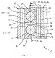
- FIG. 1 is a cross-sectional view through an inventive slewing bearing according to a first embodiment of the invention shown in detail.
- the slewing bearing 1 has an inner ring 3 and an outer ring 5.
- This in FIG. 1 shown large rolling bearing 1 is a double-row slewing bearing with a first row of balls K1 and a second row of balls K2.
- the second row of balls K2 is axially spaced from the first row of balls K1.
- the first ball row K1 includes a plurality of balls 22 arranged along a pitch diameter DL1.
- the second ball row K2 includes a plurality of balls 24 arranged along a second pitch diameter in DL2.
- the inner ring 3 has a first raceway section 7 and a second raceway section 9, which are associated with the first ball row K1.
- the inner ring 3 has a third raceway section 11 and a fourth raceway section 13, which are associated with the second ball row K2.
- the first track section 7 and the second track section 9 are arranged adjacent to one another and separated from one another by a circumferential annular groove.
- the first raceway section 7 is bounded by an annular first inner shoulder 23.
- the second raceway section 9 is bounded by an annular second inner shoulder 25.
- the first inner shoulder 23 has a maximum diameter d1.
- the second inner shoulder 25 has a second maximum diameter d2.
- the maximum diameter d1 of the first inner shoulder 23 is greater than the maximum diameter d2 of the second inner shoulder 25.
- the third raceway section 11 and the fourth raceway section 13 are arranged adjacent to each other in the inner ring 3 and separated from each other by a circumferential annular groove.
- the third raceway section 11 is bounded by an annular third inner shoulder 27.
- the fourth raceway section 13 is bounded by an annular fourth inner shoulder 29.
- the third inner shoulder 27 has a maximum diameter d3. In the in FIG. 1 In the embodiment shown, the maximum diameter d3 of the third inner shoulder 27 corresponds to the maximum diameter d2 of the second inner shoulder 25.
- the fourth inner shoulder 29 has a maximum diameter d4. In the in FIG. 1 In the embodiment shown, the maximum diameter d3 of the third inner shoulder 27 is greater than the maximum diameter d4 of the fourth inner shoulder 29.
- corresponding external shoulders are formed to the inner shoulders of the inner ring, which each define a likewise provided in the outer ring 5 raceway section.
- the outer ring 5 has in particular a first raceway section 15, and a second raceway section 17, which are associated with the first ball row K1.
- the outer ring 5 has a third raceway section 19 and a fourth raceway section 21, which are associated with the second ball row K2.
- the first raceway section 15 in the outer ring 5 is formed to the - relative to the ball 22 - diametrically opposite second raceway section 9 of the inner ring 3.
- the second raceway portion 17 in the outer ring 5 is formed corresponding to the -related to the ball 22 - diametrically opposite first raceway portion 7 of the inner ring 3.
- the third Laufbahrtabites 19 in the outer ring 5 is formed to the - relative to the ball 24 - diametrically opposite fourth raceway section 13 in the inner ring 3 corresponding.
- the fourth raceway section 21 in the outer ring 5 is formed corresponding to the third raceway section 11 diametrically opposite in relation to the ball 24 in the inner ring 3.
- the first raceway section 15 is bounded by a first annular outer shoulder 31, which has a minimum diameter D1.
- the second raceway portion 17 is bounded by a second annular outer shoulder 33 which has a minimum diameter of D2.
- the third raceway section 19 is bounded by a third annular outer shoulder 35 having a minimum diameter D3 having.
- the fourth raceway section 21 is bounded by an annular fourth outer shoulder 37, which has a minimum diameter D4.
- the balls 22 of the first row of balls K1 are arranged along a first circle diameter DL1.
- the balls 24 of the second row of balls K2 are arranged along a second circle diameter DL2.
- DL1 is according to FIG. 1 bigger than DL2.
- the area of the first raceway section 7 of the inner ring 3 is increased by the diameter d1 of the first inner shoulder 23 being larger than the diameter d2 of the second inner shoulder 25.
- d1 is also larger than DL1.
- the area of the second raceway portion 17 of the outer race is increased corresponding to the area of the first raceway portion 7 of the inner race 3 by the diameter D2 being smaller than the diameter D1 of the first outer shoulder 31.
- the diameter D2 of the second outer shoulder 33 is smaller by the same amount as the first pitch diameter DL1, as the diameter d1 of the first inner shoulder 23 is larger than DL1.
- the third raceway portion 11 has an enlarged area equal to the area of the fourth raceway portion 21 of the outer race 5.
- the diameter d3 of the third inner shoulder 27 is greater by the same amount than the running diameter DL2 of the second ball race K2, such as Diameter D4 of the fourth outer shoulder 37 of the fourth raceway section 21 of the outer ring 5 is less than the second running circle diameter DL2.
- the relation to the balls 24 diametrically opposite raceway sections 13 and 19 of the inner ring 3 and outer ring 5 are reduced in the same way relative to the raceway sections 11 and 21, as already discussed above with respect to the first ball row K1 and the raceway sections 9 and 15 ,
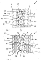
- FIG. 2 shows a slewing bearing 1 of the present invention according to a second embodiment.
- the slewing bearing 1 according to FIG. 2 similar in structure to the large rolling bearing 1 according to FIG. 1 with regard to the arrangement of the first ball row K1 and second ball row K2.
- the explanations to FIG. 1 referred, as far as identical reference numerals were assigned.
- the maximum diameter d3 of the third inner shoulder 27 in the inner ring 3 is equal to the maximum diameter d1 of the first inner shoulder 23 of the first ball row K1.
- the running circle diameter DL1 of the first ball row K1 corresponds to that in FIG FIG. 2 embodiment shown also the running circle diameter of the second ball row K2.
- the minimum diameter D3 of the third outer shoulder 35 in the outer ring 5 is again larger than the running circle diameter DL1. D3 is equal to D1.
- the maximum diameter d4 of the fourth inner shoulder 29 of the inner ring 3 is equal to the diameter d2 of the second inner shoulder 25.
- the corresponding minimum diameter D4 of the fourth outer shoulder 37 of the outer ring 5 is equal to the minimum diameter D2 of the second outer shoulder 33.
- FIG. 2 serves the running circle diameter DL1 as a reference size.
- a gap is formed, which varies by the same amount in the direction of the outer ring or inner ring, whereby diametrically opposite (relative to the respective row of balls K1, K2) uniformly enlarged and reduced track sections are formed.
- the inner ring 3 can be pushed completely through the outer ring 3 because there is no overlap.
- FIGS. 3 and 4 first show a large roller bearing 101 from the prior art.
- the slewing bearing 101 has an inner ring 103 and an outer ring 105. Between the inner ring 103 and the outer ring 105, two rows of balls K11 and K12 are arranged.
- the large-diameter bearing 101 of the prior art is a double-row four-point bearing.
- the balls of the first ball row K11 each have two points of contact with the inner ring 103 and the outer ring 105. The points of contact are each arranged in a separate raceway section 107, 109, 115 and 117.
- FIG. 4 shows the camp FIG. 3 when a large overlying axial load is introduced via the inner ring and acts on the bearing.
- the inner ring 103 is pressed against the outer ring 105 down. Due to the employment of the balls of the first row of balls K11 and the second row of balls K12 against the surfaces of the raceway portions of the inner ring 103 and the outer ring 105 are driven apart, which in FIG. 4 is shown overdrawn.
- the pressure angle ⁇ which now assumes the value ⁇ 2.
- FIGS. 5 and 6 show the improved function of the large rolling bearing according to the present invention.
- the in the FIGS. 5 and 6 Operation shown applies to both embodiments of the present invention, for the sake of simplicity, however, reference is only made to the first embodiment of the invention, which is also in FIG. 1 already shown and explained.
- FIG. 5 is the slewing bearing off FIG. 1 shown in a substantially unloaded condition.
- the points of contact of the balls 22, 24 of the first and second rows of balls K1, K2 are aligned substantially at an angle of ⁇ 1 to the radial direction of the bearing with respect to the center of the balls.
- FIG. 6 shown state loads a thrust load on the inner ring, which in the orientation shown in FIG FIG.
- the surface of the raceway sections 9, 15 of the first ball row K1 and the surface of the raceway sections 13, 19 of the second ball row K2 are substantially unloaded, but in any case much less heavily loaded than the aforementioned surfaces of the raceway sections, 7, 11, 17, 21st
- the ellipse 26 is not in the region of the annular shoulders 23, 33, 27, 37 despite the strong axial load. Consequently, no wear of the balls and / or raceway sections occurs of the inner ring 3 and outer ring 5.
- no critical operating state has yet been reached in the bearing according to the invention.
- the present embodiments of preferred embodiments and the above description of the figures relate to double-row bearings.
- the invention additionally also relates to further, multi-row embodiments of the slewing bearing according to the present invention.
- the invention relates to a three-row slewing bearing, which has a third row of balls.
- the third row of balls is arranged between the inner ring and the outer ring in a four-point bearing, wherein the third row of balls to the first row of balls and the second Ball row axially spaced, the third row of balls are associated with four track sections, each having a surface for receiving the ball track, and wherein the surface of each provided in the inner ring raceway section of the third row of balls is larger than the surface of each adjacent provided in the inner ring Track section of the third row of balls and equal to the surface of the respective diametrically opposite provided in the outer ring raceway section of the third row of balls.
- Preferred embodiments which have been described above with reference to double-row versions of the large rolling bearing, are to be transferred in an analogous manner to the three-row design of the large roller bearing.
- the large rolling bearings according to the invention are preferably adapted to different deployment areas by means of further design details.
- the large rolling bearings according to the invention for example, have internal teeth, external teeth or no teeth.
- the large rolling bearings may have continuous, axially extending mounting holes or other, flange or radial mounting holes.
- the bearings according to the invention preferably have spacers between the balls, or cages for holding the balls.
- the large rolling bearings according to the invention have lubrication holes for filling and squeezing of lubricants, or openings for filling or removing the balls from the rows of balls.
Claims (18)
- Couronne d'orientation (1), qui est réalisée sous la forme d'un raccordement rotatif à plusieurs rangées de billes servant à recevoir des charges axiales, des charges radiales et des couples de basculement, comprenant une bague extérieure (5), une bague intérieure (3), une première rangée de billes (K1) et une deuxième rangée de billes (K2), sachant que la première rangée de billes (K1) et la deuxième rangée de billes (K2) sont disposées de manière espacée l'une de l'autre axialement respectivement dans un palier de support à quatre points, sachant que quatre tronçons de voie de roulement (7, 9, 15, 17) sont associés à la première rangée de billes et que quatre tronçons de voie de roulement (11, 13, 19, 21) sont associés à la deuxième rangée de billes, lesquels présentent respectivement une surface servant à recevoir la voie de roulement des billes,
caractérisée en ce que la surface respectivement d'un tronçon de voie de roulement (7, 11) prévu dans la bague intérieure est plus grande que la surface du tronçon de voie de roulement (9, 13) respectivement adjacent, prévu dans la bague intérieure, et en ce qu'elle est égale à la surface du tronçon de voie de roulement (17, 21) respectivement diamétralement opposé, prévu dans la bague extérieure. - Couronne d'orientation (1) selon la revendication 1,
caractérisée en ce que la surface du tronçon de voie de roulement (9, 13) prévu dans la bague intérieure (3) est égale à la surface du tronçon de voie de roulement (15, 19) respectivement diamétralement opposé prévu dans la bague extérieure (5). - Couronne d'orientation (1) selon l'une des revendications précédentes,
caractérisée en ce que la bague intérieure (3) pour la première rangée de billes (K1) présente un premier épaulement intérieur (23) de forme annulaire et un deuxième épaulement intérieur (25) de forme annulaire, lesquels délimitent respectivement une des surfaces servant à recevoir une voie de roulement de billes de la première rangée de billes (K1), et en ce que la bague intérieure (3) pour la deuxième rangée de billes (K2) présente un troisième épaulement intérieur (27) de forme annulaire et un quatrième épaulement intérieur (29) de forme annulaire, lesquels délimitent respectivement une des surfaces servant à recevoir la voie de roulement de billes de la deuxième rangée de billes (K2), sachant qu'un diamètre maximal (d4) du quatrième épaulement intérieur (29) est différent d'un diamètre maximal (d1) du premier épaulement intérieur (23). - Couronne d'orientation (1) selon l'une des revendications précédentes,
caractérisée en ce que le diamètre maximal (d3) du troisième épaulement intérieur (27) est différent du diamètre maximal (d2) du deuxième épaulement intérieur (25). - Couronne d'orientation (1) selon l'une des revendications précédentes,
caractérisée en ce que la bague extérieure (5) pour la première rangée de billes (K1) présente un premier épaulement extérieur (31) de forme annulaire et un deuxième épaulement extérieur (33) de forme annulaire, lesquels délimitent respectivement une des surfaces servant à recevoir les voies de roulement de billes de la première rangée de billes (K1), et
en ce que la bague extérieure (5) pour la deuxième rangée de billes (K2) présente un troisième épaulement extérieur (35) de forme annulaire et un quatrième épaulement extérieur (37) de forme annulaire, lesquels délimitent respectivement une des surfaces servant à recevoir les voies de roulement de billes de la deuxième rangée de billes (K2),
sachant que le diamètre minimal (D4) du quatrième épaulement extérieur (37) est différent du diamètre minimal (D1) du premier épaulement extérieur (31). - Couronne d'orientation (1) selon l'une des revendications précédentes,
caractérisée en ce que le diamètre minimal (D3) du troisième épaulement extérieur (35) est différent du diamètre minimal (D2) du deuxième épaulement extérieur (33). - Couronne d'orientation (1) selon l'une des revendications précédentes,
caractérisée en ce que le plus grand des diamètres maximaux (d1, d2, d3, d4) des épaulements intérieurs (23, 25, 27, 29) est inférieur ou égal au plus petit des diamètres minimaux (D1, D2, D3, D4) des épaulements extérieurs (31, 33, 35, 37). - Couronne d'orientation (1) selon l'une des revendications précédentes,
caractérisée en ce que les billes (23) de la première rangée de billes (K1) et les billes (24) de la deuxième rangée de billes (K2) sont disposées le long d'un premier diamètre de circuit de roulement (DL1). - Couronne d'orientation (1) selon la revendication 8,
caractérisée en ce que le plus grand des diamètres maximaux (d1, d2, d3, d4) des épaulements intérieurs (23, 25, 27, 29) est égal ou se situe dans une plage allant jusqu'à 0,5 mm en dessous du premier diamètre de circuit de roulement (DL1) de la première et de la deuxième rangée de billes. - Couronne d'orientation (1) selon la revendication 8 ou 9,
caractérisée en ce que le plus petit des diamètres minimaux (D1, D2, D3, D4) des épaulements extérieurs (31, 33, 35, 37) est égal ou se situe dans une plage allant jusqu'à 0,5 mm au-dessus du premier diamètre de circuit de roulement (DL1) de la première et de la deuxième rangée de billes. - Couronne d'orientation (1) selon la revendication 9 ou 10,
caractérisée en ce que le diamètre maximal (d1) du premier épaulement intérieur (23) est égal au diamètre maximal (d3) du troisième épaulement intérieur (27), et est plus grand que le diamètre maximal (d2, d4) respectivement du deuxième et du quatrième épaulement intérieur (25, 29). - Couronne d'orientation (1) selon l'une des revendications précédentes,
caractérisée en ce que le diamètre minimal (D2) du deuxième épaulement extérieur (33) est égal au diamètre minimal (D4) du quatrième épaulement extérieur (37) et est inférieur au diamètre minimal (D1, D3) respectivement du premier et du troisième épaulement extérieur (31, 35). - Couronne d'orientation (1) selon l'une des revendications précédentes,
caractérisée en ce que les billes (23) de la première rangée de billes (K1) sont disposées le long du premier diamètre de circuit de roulement (DL1), et en ce que les billes (24) de la deuxième rangée de bille (K2) sont disposées le long d'un deuxième diamètre de circuit de roulement (DL2), lequel est différent du diamètre (DL1) de la première rangée de billes (K1). - Couronne d'orientation (1) selon la revendication 13,
caractérisée en ce que le diamètre maximal (d1) du premier épaulement intérieur (23) est plus grand que le diamètre maximal (d2) du deuxième épaulement intérieur (25), et en ce que le diamètre maximal (d3) du troisième épaulement intérieur (27) est plus grand que le diamètre maximal (d4) du quatrième épaulement intérieur (29). - Couronne d'orientation (1) selon la revendication 13 ou 14,
caractérisée en ce que le diamètre minimal (D4) du quatrième épaulement extérieur (37) est plus petit que le diamètre minimal (D3) du troisième épaulement extérieur (35), et en ce que le diamètre minimal (D2) du deuxième épaulement extérieur (33) est inférieur au diamètre minimal (D1) du premier épaulement extérieur (31). - Couronne d'orientation (1) selon l'une des revendications précédentes,
caractérisée en ce que la première rangée de billes (K1) est constituée de billes (23) présentant un premier diamètre de bille, et en ce que la deuxième rangée de billes (K2) est constituée de billes (24) présentant un deuxième diamètre de bille, qui est différent du premier diamètre de bille. - Couronne d'orientation (1) selon l'une des revendications précédentes,
caractérisée en ce que la couronne d'orientation (1) présente une ou plusieurs autres rangées de billes, sachant que les une ou plusieurs rangées de billes sont disposées, de manière espacée les unes des autres axialement, respectivement dans un palier de support à quatre points, sachant que quatre tronçons de voie de roulement sont associés à respectivement une rangée de billes, lesquels présentent respectivement une surface servant à recevoir la voie de roulement de bille, et sachant que la surface respectivement d'un tronçon de voie de roulement prévu dans la bague intérieure est plus grande que la surface du tronçon de voie de roulement respectivement adjacent, prévu dans la bague intérieure et est égale à la surface du tronçon de voie de roulement respectivement diamétralement opposé prévu dans la bague extérieure. - Eolienne, comprenant
une tour, qui présente une tête de tour, et une nacelle, qui est mise en place afin de recevoir un rotor, sachant que la nacelle est montée de manière à pouvoir tourner par rapport à la tour au moyen d'un palier azimutal,
caractérisée en ce que le palier azimutal est réalisé sous la forme d'une couronne d'orientation (1) selon l'une quelconque des revendications 1 à 17.
Priority Applications (6)
| Application Number | Priority Date | Filing Date | Title |
|---|---|---|---|
| SI201230243T SI2715162T2 (sl) | 2011-06-01 | 2012-05-21 | Velik kotalni ležaj |
| RS20150349A RS54029B2 (sr) | 2011-06-01 | 2012-05-21 | Veliki kotrljajući ležaj |
| PL12722732.0T PL2715162T5 (pl) | 2011-06-01 | 2012-05-21 | Wielkogabarytowe łożysko toczne |
| MEP-2015-75A ME02116B (me) | 2011-06-01 | 2012-05-21 | Veliki kotrljajući ležaj |
| HRP20150538TT HRP20150538T4 (hr) | 2011-06-01 | 2015-05-19 | Veliki kotrljajući ležaj |
| CY20151100565T CY1116570T1 (el) | 2011-06-01 | 2015-06-30 | Ογκωδες εδρανο κυλισης |
Applications Claiming Priority (2)
| Application Number | Priority Date | Filing Date | Title |
|---|---|---|---|
| DE102011076872A DE102011076872A1 (de) | 2011-06-01 | 2011-06-01 | Großwälzlager |
| PCT/EP2012/059342 WO2012163707A1 (fr) | 2011-06-01 | 2012-05-21 | Couronne d'orientation |
Publications (3)
| Publication Number | Publication Date |
|---|---|
| EP2715162A1 EP2715162A1 (fr) | 2014-04-09 |
| EP2715162B1 true EP2715162B1 (fr) | 2015-05-13 |
| EP2715162B2 EP2715162B2 (fr) | 2018-08-15 |
Family
ID=46147452
Family Applications (1)
| Application Number | Title | Priority Date | Filing Date |
|---|---|---|---|
| EP12722732.0A Active EP2715162B2 (fr) | 2011-06-01 | 2012-05-21 | Couronne d'orientation |
Country Status (26)
| Country | Link |
|---|---|
| US (1) | US9541126B2 (fr) |
| EP (1) | EP2715162B2 (fr) |
| JP (2) | JP5797331B2 (fr) |
| KR (1) | KR101494570B1 (fr) |
| CN (1) | CN103562574B (fr) |
| AR (1) | AR086628A1 (fr) |
| AU (1) | AU2012264981B2 (fr) |
| BR (1) | BR112013027326A2 (fr) |
| CA (1) | CA2832201C (fr) |
| CL (1) | CL2013003441A1 (fr) |
| CY (1) | CY1116570T1 (fr) |
| DE (1) | DE102011076872A1 (fr) |
| DK (1) | DK2715162T4 (fr) |
| ES (1) | ES2543444T5 (fr) |
| HR (1) | HRP20150538T4 (fr) |
| HU (1) | HUE025337T2 (fr) |
| ME (1) | ME02116B (fr) |
| MX (1) | MX2013012035A (fr) |
| PL (1) | PL2715162T5 (fr) |
| PT (1) | PT2715162E (fr) |
| RS (1) | RS54029B2 (fr) |
| RU (1) | RU2570240C1 (fr) |
| SI (1) | SI2715162T2 (fr) |
| TW (1) | TWI499726B (fr) |
| WO (1) | WO2012163707A1 (fr) |
| ZA (1) | ZA201307204B (fr) |
Families Citing this family (11)
| Publication number | Priority date | Publication date | Assignee | Title |
|---|---|---|---|---|
| US9188107B2 (en) * | 2013-08-30 | 2015-11-17 | General Electric Company | Wind turbine bearings |
| DE102014216522A1 (de) | 2014-08-20 | 2016-02-25 | Schaeffler Technologies AG & Co. KG | Kugellager |
| US11725633B2 (en) * | 2017-03-28 | 2023-08-15 | General Electric Company | Pitch bearing for a wind turbine |
| WO2018194025A1 (fr) * | 2017-04-17 | 2018-10-25 | Ntn株式会社 | Palier d'orientation et son procédé de traitement |
| JP2018204681A (ja) * | 2017-06-02 | 2018-12-27 | 株式会社不二越 | 複列4点接触玉軸受 |
| EP3788260A4 (fr) * | 2018-05-03 | 2021-11-24 | General Electric Company | Palier de pas pour une éolienne |
| DE102018208320B4 (de) * | 2018-05-25 | 2020-03-05 | Thyssenkrupp Ag | Doppelvierpunktlager |
| DE202019101697U1 (de) * | 2019-03-26 | 2020-07-02 | Liebherr-Components Biberach Gmbh | Großwälzlager |
| CN110848267A (zh) * | 2019-12-27 | 2020-02-28 | 瓦房店轴承集团国家轴承工程技术研究中心有限公司 | S形定位回转径结构的偏航轴承 |
| CN111347178A (zh) * | 2020-05-13 | 2020-06-30 | 常州奥旋重型轴承有限公司 | 一种用于激光切割设备上带底板的整体式轴承 |
| EP4043743B1 (fr) * | 2021-02-12 | 2023-10-04 | Siemens Gamesa Renewable Energy A/S | Palier d'éolienne, éolienne comprenant un palier et procédé de fabrication d'une bague de palier |
Citations (5)
| Publication number | Priority date | Publication date | Assignee | Title |
|---|---|---|---|---|
| DD46126A5 (de) | 1964-01-13 | 1966-03-05 | Rothe Erde Eisenwerk | Einreihige Kugeldrehverbindung |
| WO1999002873A1 (fr) | 1997-07-10 | 1999-01-21 | Skf Engineering & Research Centre B.V. | Butee a billes a contact oblique et asymetrique |
| DE202006007434U1 (de) | 2005-07-06 | 2006-11-09 | Rothe Erde Gmbh | Großwälzlager |
| JP2009047206A (ja) | 2007-08-16 | 2009-03-05 | Antetsukusu:Kk | 旋回座軸受 |
| US20110085756A1 (en) | 2008-06-06 | 2011-04-14 | Ntn Corporation | Swing bearing and method of processing raceway groove of the same |
Family Cites Families (20)
| Publication number | Priority date | Publication date | Assignee | Title |
|---|---|---|---|---|
| DE1855303U (de) * | 1959-12-12 | 1962-07-19 | Rothe Erde Eisenwerk | Waelzlager. |
| RU2095650C1 (ru) | 1992-04-13 | 1997-11-10 | Василий Васильевич Онищенко | Конический шариковый подшипник |
| US6015264A (en) * | 1997-08-15 | 2000-01-18 | United Technologies Corporation | Preloaded retention assembly for aircraft propeller blade retention |
| US6827496B2 (en) * | 2001-08-28 | 2004-12-07 | Koyo Seiko Co., Ltd. | Four-point contact ball bearing |
| JP2003097564A (ja) * | 2001-09-25 | 2003-04-03 | Harmonic Drive Syst Ind Co Ltd | 4点接触ボールベアリング |
| US7416343B2 (en) | 2002-07-12 | 2008-08-26 | Nsk Ltd. | Pulley support double row ball bearing |
| DE102004021054B4 (de) | 2004-04-29 | 2014-09-18 | Infineon Technologies Ag | Halbleiterbauelement und Verfahren zu seiner Herstellung |
| DE102004023774A1 (de) * | 2004-05-11 | 2005-12-22 | Repower Systems Ag | Windenergieanlage |
| TWI246175B (en) | 2004-10-11 | 2005-12-21 | Ind Tech Res Inst | Bonding structure of device packaging |
| DE102004051054A1 (de) * | 2004-10-19 | 2006-04-20 | Repower Systems Ag | Vorrichtung für eine Windenergieanlage |
| JP2006118591A (ja) * | 2004-10-21 | 2006-05-11 | Nachi Fujikoshi Corp | 多点接触玉軸受 |
| DE102006003156A1 (de) | 2006-01-24 | 2007-07-26 | Daimlerchrysler Ag | Verfahren und Vorrichtung zur Vorhersage des Verlaufs einer zeitlich veränderlichen Größe |
| DE102006004297B4 (de) * | 2006-01-31 | 2019-03-07 | Schaeffler Kg | Asymmetrisches dreireihiges Wälzlager |
| DE102006031956A1 (de) * | 2006-07-11 | 2008-01-17 | Schaeffler Kg | Zweireihiges Kugellager |
| JP2010002011A (ja) * | 2008-06-20 | 2010-01-07 | Ntn Corp | 旋回軸受 |
| DE102008049813A1 (de) * | 2008-09-30 | 2010-04-01 | Schaeffler Kg | Drehverbindung, zum Beispiel für eine Windenergieanlage sowie Windenergieanlage mit der Drehverbindung |
| WO2010043248A1 (fr) * | 2008-10-14 | 2010-04-22 | Aktiebolaget Skf | Joint pour roulement à billes, en particulier pour un roulement à billes utilisé dans une éolienne |
| JP2010265095A (ja) | 2009-05-15 | 2010-11-25 | Iguchi Kiko Seisakusho:Kk | ベアリングユニット、フリーボールベアリング、支持テーブル、搬送設備、ターンテーブル |
| JP5763292B2 (ja) * | 2009-07-27 | 2015-08-12 | Ntn株式会社 | 旋回軸受 |
| EP3372852B1 (fr) * | 2009-11-19 | 2019-08-21 | NSK Ltd. | Dispositif de support de rotation pour arbre-pignon |
-
2011
- 2011-06-01 DE DE102011076872A patent/DE102011076872A1/de not_active Withdrawn
-
2012
- 2012-05-21 US US14/122,988 patent/US9541126B2/en active Active
- 2012-05-21 RU RU2013158948/11A patent/RU2570240C1/ru active
- 2012-05-21 HU HUE12722732A patent/HUE025337T2/en unknown
- 2012-05-21 JP JP2014513116A patent/JP5797331B2/ja active Active
- 2012-05-21 SI SI201230243T patent/SI2715162T2/sl unknown
- 2012-05-21 ME MEP-2015-75A patent/ME02116B/me unknown
- 2012-05-21 EP EP12722732.0A patent/EP2715162B2/fr active Active
- 2012-05-21 CA CA2832201A patent/CA2832201C/fr not_active Expired - Fee Related
- 2012-05-21 PT PT127227320T patent/PT2715162E/pt unknown
- 2012-05-21 RS RS20150349A patent/RS54029B2/sr unknown
- 2012-05-21 AU AU2012264981A patent/AU2012264981B2/en not_active Ceased
- 2012-05-21 DK DK12722732.0T patent/DK2715162T4/en active
- 2012-05-21 MX MX2013012035A patent/MX2013012035A/es unknown
- 2012-05-21 KR KR1020137032171A patent/KR101494570B1/ko active IP Right Grant
- 2012-05-21 BR BR112013027326-7A patent/BR112013027326A2/pt not_active Application Discontinuation
- 2012-05-21 WO PCT/EP2012/059342 patent/WO2012163707A1/fr active Application Filing
- 2012-05-21 ES ES12722732T patent/ES2543444T5/es active Active
- 2012-05-21 PL PL12722732.0T patent/PL2715162T5/pl unknown
- 2012-05-21 CN CN201280026918.2A patent/CN103562574B/zh active Active
- 2012-05-31 TW TW101119622A patent/TWI499726B/zh not_active IP Right Cessation
- 2012-06-01 AR ARP120101930A patent/AR086628A1/es active IP Right Grant
-
2013
- 2013-09-26 ZA ZA2013/07204A patent/ZA201307204B/en unknown
- 2013-11-29 CL CL2013003441A patent/CL2013003441A1/es unknown
-
2015
- 2015-02-09 JP JP2015023136A patent/JP6267844B2/ja not_active Expired - Fee Related
- 2015-05-19 HR HRP20150538TT patent/HRP20150538T4/hr unknown
- 2015-06-30 CY CY20151100565T patent/CY1116570T1/el unknown
Patent Citations (5)
| Publication number | Priority date | Publication date | Assignee | Title |
|---|---|---|---|---|
| DD46126A5 (de) | 1964-01-13 | 1966-03-05 | Rothe Erde Eisenwerk | Einreihige Kugeldrehverbindung |
| WO1999002873A1 (fr) | 1997-07-10 | 1999-01-21 | Skf Engineering & Research Centre B.V. | Butee a billes a contact oblique et asymetrique |
| DE202006007434U1 (de) | 2005-07-06 | 2006-11-09 | Rothe Erde Gmbh | Großwälzlager |
| JP2009047206A (ja) | 2007-08-16 | 2009-03-05 | Antetsukusu:Kk | 旋回座軸受 |
| US20110085756A1 (en) | 2008-06-06 | 2011-04-14 | Ntn Corporation | Swing bearing and method of processing raceway groove of the same |
Non-Patent Citations (5)
| Title |
|---|
| BEGLAUBIGTE ÜBERSETZUNG D3 |
| ROTHE ERDE GROSSWÄLZLAGER, April 2007 (2007-04-01), XP055259708 |
| ROTHE ERDE GROSSWÄLZLAGER, August 2003 (2003-08-01) |
| VERÖFFENTLICHUNGSNACHWEIS E1 |
| VERÖFFENTLICHUNGSNACHWEIS E2 |
Also Published As
Similar Documents
| Publication | Publication Date | Title |
|---|---|---|
| EP2715162B1 (fr) | Couronne d'orientation | |
| EP2948688B1 (fr) | Roulement à rouleaux cylindriques | |
| WO2008131721A2 (fr) | Couronne d'orientation à plusieurs rangées, en particulier palier axial-radial servant de palier principal à l'arbre de rotor d'une éolienne | |
| EP2387664A2 (fr) | Éolienne | |
| DE102014104863B4 (de) | Wälzlageranordnung und Windkraftanlage | |
| EP3332134B1 (fr) | Roulement à rouleaux à contact oblique ainsi que procédé et dispositif pour son montage | |
| EP2676042A1 (fr) | Palier à roulements axiaux-radiaux, en particulier pour le montage de pales de rotor sur une éolienne | |
| EP3721104B1 (fr) | Agencement de paliers a roulement | |
| WO2018189143A1 (fr) | Ensemble palier servant à supporter une pale de rotor d'une éolienne | |
| WO2015150159A1 (fr) | Ensemble palier à roulement et éolienne | |
| DE102011083824A1 (de) | Drehverbindung für eine Arbeitsmaschine | |
| DE102009035750A1 (de) | Einlagerkonstruktion sowie Windkraftanlage mit der Einlagerkonstruktion | |
| EP2507522B1 (fr) | Roulement à billes | |
| EP3601819A1 (fr) | Ensemble palier à roulement et éolienne | |
| DE102010054319A1 (de) | Rotorlagerung einer Windkraftanlage | |
| WO2009059585A2 (fr) | Montage d'une roue planétaire pour optimiser la répartition des charges | |
| EP3870869B1 (fr) | Ensemble de paliers à roulement et éolienne | |
| DE102007055362A1 (de) | Wälzlager für ein wellenförmiges Bauteil | |
| EP2594750B1 (fr) | Dispositif de palier et turbomachine avec dispositif de palier | |
| DE102010011462A1 (de) | Kegelrollenlager mit profilierter Laufbahn | |
| EP3685059B1 (fr) | Roulement à rouleaux à contact oblique | |
| EP3670948B1 (fr) | Palier à roulement pourvu de bague d'arrêt radiale permettant de limiter la déformation radiale du palier à roulement | |
| EP3721103B1 (fr) | Assemblage de paliers roulants | |
| EP3421789B1 (fr) | Palier à roulement pour chaîne cinématique de l'éolienne | |
| DE102017219831A1 (de) | System zur Lagerung einer Rotorwelle |
Legal Events
| Date | Code | Title | Description |
|---|---|---|---|
| PUAI | Public reference made under article 153(3) epc to a published international application that has entered the european phase |
Free format text: ORIGINAL CODE: 0009012 |
|
| 17P | Request for examination filed |
Effective date: 20140102 |
|
| AK | Designated contracting states |
Kind code of ref document: A1 Designated state(s): AL AT BE BG CH CY CZ DE DK EE ES FI FR GB GR HR HU IE IS IT LI LT LU LV MC MK MT NL NO PL PT RO RS SE SI SK SM TR |
|
| AX | Request for extension of the european patent |
Extension state: BA ME |
|
| GRAP | Despatch of communication of intention to grant a patent |
Free format text: ORIGINAL CODE: EPIDOSNIGR1 |
|
| INTG | Intention to grant announced |
Effective date: 20150115 |
|
| GRAS | Grant fee paid |
Free format text: ORIGINAL CODE: EPIDOSNIGR3 |
|
| GRAA | (expected) grant |
Free format text: ORIGINAL CODE: 0009210 |
|
| AK | Designated contracting states |
Kind code of ref document: B1 Designated state(s): AL AT BE BG CH CY CZ DE DK EE ES FI FR GB GR HR HU IE IS IT LI LT LU LV MC MK MT NL NO PL PT RO RS SE SI SK SM TR |
|
| AX | Request for extension of the european patent |
Extension state: BA ME |
|
| REG | Reference to a national code |
Ref country code: GB Ref legal event code: FG4D Free format text: NOT ENGLISH |
|
| REG | Reference to a national code |
Ref country code: CH Ref legal event code: NV Representative=s name: WEINMANN ZIMMERLI, CH Ref country code: CH Ref legal event code: EP |
|
| REG | Reference to a national code |
Ref country code: HR Ref legal event code: TUEP Ref document number: P20150538 Country of ref document: HR |
|
| REG | Reference to a national code |
Ref country code: FR Ref legal event code: PLFP Year of fee payment: 4 |
|
| REG | Reference to a national code |
Ref country code: DK Ref legal event code: T3 Effective date: 20150527 |
|
| REG | Reference to a national code |
Ref country code: IE Ref legal event code: FG4D Free format text: LANGUAGE OF EP DOCUMENT: GERMAN |
|
| REG | Reference to a national code |
Ref country code: AT Ref legal event code: REF Ref document number: 726970 Country of ref document: AT Kind code of ref document: T Effective date: 20150615 |
|
| REG | Reference to a national code |
Ref country code: NL Ref legal event code: T3 |
|
| REG | Reference to a national code |
Ref country code: HR Ref legal event code: T1PR Ref document number: P20150538 Country of ref document: HR |
|
| REG | Reference to a national code |
Ref country code: DE Ref legal event code: R096 Ref document number: 502012003156 Country of ref document: DE Effective date: 20150625 |
|
| REG | Reference to a national code |
Ref country code: NL Ref legal event code: T3 |
|
| REG | Reference to a national code |
Ref country code: EE Ref legal event code: FG4A Ref document number: E010626 Country of ref document: EE Effective date: 20150609 |
|
| REG | Reference to a national code |
Ref country code: RO Ref legal event code: EPE |
|
| REG | Reference to a national code |
Ref country code: SE Ref legal event code: TRGR |
|
| REG | Reference to a national code |
Ref country code: ES Ref legal event code: FG2A Ref document number: 2543444 Country of ref document: ES Kind code of ref document: T3 Effective date: 20150819 |
|
| REG | Reference to a national code |
Ref country code: PT Ref legal event code: SC4A Free format text: AVAILABILITY OF NATIONAL TRANSLATION Effective date: 20150812 |
|
| REG | Reference to a national code |
Ref country code: NO Ref legal event code: T2 Effective date: 20150513 |
|
| REG | Reference to a national code |
Ref country code: PL Ref legal event code: T3 |
|
| REG | Reference to a national code |
Ref country code: SK Ref legal event code: T3 Ref document number: E 19094 Country of ref document: SK |
|
| REG | Reference to a national code |
Ref country code: GR Ref legal event code: EP Ref document number: 20150401324 Country of ref document: GR Effective date: 20150901 |
|
| RAP2 | Party data changed (patent owner data changed or rights of a patent transferred) |
Owner name: WOBBEN PROPERTIES GMBH |
|
| REG | Reference to a national code |
Ref country code: DE Ref legal event code: R026 Ref document number: 502012003156 Country of ref document: DE |
|
| PLBI | Opposition filed |
Free format text: ORIGINAL CODE: 0009260 |
|
| PG25 | Lapsed in a contracting state [announced via postgrant information from national office to epo] |
Ref country code: MC Free format text: LAPSE BECAUSE OF FAILURE TO SUBMIT A TRANSLATION OF THE DESCRIPTION OR TO PAY THE FEE WITHIN THE PRESCRIBED TIME-LIMIT Effective date: 20150513 |
|
| REG | Reference to a national code |
Ref country code: HU Ref legal event code: AG4A Ref document number: E025337 Country of ref document: HU |
|
| PLAX | Notice of opposition and request to file observation + time limit sent |
Free format text: ORIGINAL CODE: EPIDOSNOBS2 |
|
| 26 | Opposition filed |
Opponent name: SENVION GMBH Effective date: 20160211 |
|
| REG | Reference to a national code |
Ref country code: FR Ref legal event code: PLFP Year of fee payment: 5 |
|
| PLAB | Opposition data, opponent's data or that of the opponent's representative modified |
Free format text: ORIGINAL CODE: 0009299OPPO |
|
| PLAF | Information modified related to communication of a notice of opposition and request to file observations + time limit |
Free format text: ORIGINAL CODE: EPIDOSCOBS2 |
|
| R26 | Opposition filed (corrected) |
Opponent name: SENVION GMBH Effective date: 20160211 |
|
| PLBB | Reply of patent proprietor to notice(s) of opposition received |
Free format text: ORIGINAL CODE: EPIDOSNOBS3 |
|
| REG | Reference to a national code |
Ref country code: FR Ref legal event code: PLFP Year of fee payment: 6 |
|
| PG25 | Lapsed in a contracting state [announced via postgrant information from national office to epo] |
Ref country code: SM Free format text: LAPSE BECAUSE OF FAILURE TO SUBMIT A TRANSLATION OF THE DESCRIPTION OR TO PAY THE FEE WITHIN THE PRESCRIBED TIME-LIMIT Effective date: 20150513 |
|
| REG | Reference to a national code |
Ref country code: FR Ref legal event code: PLFP Year of fee payment: 7 |
|
| PUAH | Patent maintained in amended form |
Free format text: ORIGINAL CODE: 0009272 |
|
| STAA | Information on the status of an ep patent application or granted ep patent |
Free format text: STATUS: PATENT MAINTAINED AS AMENDED |
|
| REG | Reference to a national code |
Ref country code: CH Ref legal event code: AELC |
|
| 27A | Patent maintained in amended form |
Effective date: 20180815 |
|
| AK | Designated contracting states |
Kind code of ref document: B2 Designated state(s): AL AT BE BG CH CY CZ DE DK EE ES FI FR GB GR HR HU IE IS IT LI LT LU LV MC MK MT NL NO PL PT RO RS SE SI SK SM TR |
|
| AX | Request for extension of the european patent |
Extension state: BA ME |
|
| REG | Reference to a national code |
Ref country code: DE Ref legal event code: R102 Ref document number: 502012003156 Country of ref document: DE |
|
| REG | Reference to a national code |
Ref country code: EE Ref legal event code: LD4A Ref document number: E010626 Country of ref document: EE |
|
| REG | Reference to a national code |
Ref country code: DK Ref legal event code: T4 Effective date: 20181105 |
|
| REG | Reference to a national code |
Ref country code: SE Ref legal event code: RPEO |
|
| REG | Reference to a national code |
Ref country code: HR Ref legal event code: T4IZ Ref document number: P20150538 Country of ref document: HR |
|
| REG | Reference to a national code |
Ref country code: NL Ref legal event code: FP |
|
| REG | Reference to a national code |
Ref country code: NO Ref legal event code: TB2 |
|
| REG | Reference to a national code |
Ref country code: ES Ref legal event code: DC2A Ref document number: 2543444 Country of ref document: ES Kind code of ref document: T5 Effective date: 20190114 |
|
| REG | Reference to a national code |
Ref country code: HU Ref legal event code: HC9C Owner name: WOBBEN PROPERTIES GMBH, DE Free format text: FORMER OWNER(S): WOBBEN PROPERTIES GMBH, DE |
|
| REG | Reference to a national code |
Ref country code: GR Ref legal event code: EP Ref document number: 20180402992 Country of ref document: GR Effective date: 20190225 |
|
| REG | Reference to a national code |
Ref country code: SK Ref legal event code: T5 Ref document number: E 19094 Country of ref document: SK |
|
| REG | Reference to a national code |
Ref country code: HR Ref legal event code: ODRP Ref document number: P20150538 Country of ref document: HR Payment date: 20190513 Year of fee payment: 8 |
|
| REG | Reference to a national code |
Ref country code: HR Ref legal event code: ODRP Ref document number: P20150538 Country of ref document: HR Payment date: 20200512 Year of fee payment: 9 |
|
| PGFP | Annual fee paid to national office [announced via postgrant information from national office to epo] |
Ref country code: GR Payment date: 20200518 Year of fee payment: 9 Ref country code: CZ Payment date: 20200511 Year of fee payment: 9 Ref country code: LU Payment date: 20200518 Year of fee payment: 9 Ref country code: IE Payment date: 20200519 Year of fee payment: 9 Ref country code: LT Payment date: 20200507 Year of fee payment: 9 Ref country code: RO Payment date: 20200511 Year of fee payment: 9 Ref country code: FR Payment date: 20200519 Year of fee payment: 9 Ref country code: ES Payment date: 20200618 Year of fee payment: 9 Ref country code: PT Payment date: 20200507 Year of fee payment: 9 Ref country code: TR Payment date: 20200515 Year of fee payment: 9 Ref country code: EE Payment date: 20200518 Year of fee payment: 9 Ref country code: NO Payment date: 20200519 Year of fee payment: 9 Ref country code: FI Payment date: 20200515 Year of fee payment: 9 Ref country code: CY Payment date: 20200520 Year of fee payment: 9 Ref country code: CH Payment date: 20200522 Year of fee payment: 9 |
|
| PGFP | Annual fee paid to national office [announced via postgrant information from national office to epo] |
Ref country code: PL Payment date: 20200416 Year of fee payment: 9 Ref country code: GB Payment date: 20200522 Year of fee payment: 9 Ref country code: HU Payment date: 20200509 Year of fee payment: 9 Ref country code: SI Payment date: 20200508 Year of fee payment: 9 Ref country code: BE Payment date: 20200518 Year of fee payment: 9 Ref country code: SE Payment date: 20200525 Year of fee payment: 9 Ref country code: BG Payment date: 20200526 Year of fee payment: 9 Ref country code: SK Payment date: 20200507 Year of fee payment: 9 Ref country code: HR Payment date: 20200512 Year of fee payment: 9 Ref country code: RS Payment date: 20200521 Year of fee payment: 9 Ref country code: LV Payment date: 20200518 Year of fee payment: 9 Ref country code: IS Payment date: 20200515 Year of fee payment: 9 Ref country code: IT Payment date: 20200528 Year of fee payment: 9 |
|
| PGFP | Annual fee paid to national office [announced via postgrant information from national office to epo] |
Ref country code: MK Payment date: 20200514 Year of fee payment: 9 Ref country code: MT Payment date: 20200525 Year of fee payment: 9 Ref country code: AT Payment date: 20200515 Year of fee payment: 9 |
|
| PGFP | Annual fee paid to national office [announced via postgrant information from national office to epo] |
Ref country code: AL Payment date: 20200424 Year of fee payment: 9 |
|
| REG | Reference to a national code |
Ref country code: HR Ref legal event code: PBON Ref document number: P20150538 Country of ref document: HR Effective date: 20210521 |
|
| REG | Reference to a national code |
Ref country code: FI Ref legal event code: MAE |
|
| REG | Reference to a national code |
Ref country code: EE Ref legal event code: MM4A Ref document number: E010626 Country of ref document: EE Effective date: 20210531 |
|
| REG | Reference to a national code |
Ref country code: NO Ref legal event code: MMEP Ref country code: LT Ref legal event code: MM4D Effective date: 20210521 |
|
| REG | Reference to a national code |
Ref country code: SE Ref legal event code: EUG |
|
| REG | Reference to a national code |
Ref country code: CH Ref legal event code: PL |
|
| REG | Reference to a national code |
Ref country code: AT Ref legal event code: MM01 Ref document number: 726970 Country of ref document: AT Kind code of ref document: T Effective date: 20210521 |
|
| GBPC | Gb: european patent ceased through non-payment of renewal fee |
Effective date: 20210521 |
|
| REG | Reference to a national code |
Ref country code: SK Ref legal event code: MM4A Ref document number: E 19094 Country of ref document: SK Effective date: 20210521 |
|
| PG25 | Lapsed in a contracting state [announced via postgrant information from national office to epo] |
Ref country code: CY Free format text: LAPSE BECAUSE OF NON-PAYMENT OF DUE FEES Effective date: 20210521 Ref country code: CZ Free format text: LAPSE BECAUSE OF NON-PAYMENT OF DUE FEES Effective date: 20210521 Ref country code: EE Free format text: LAPSE BECAUSE OF NON-PAYMENT OF DUE FEES Effective date: 20210531 Ref country code: SK Free format text: LAPSE BECAUSE OF NON-PAYMENT OF DUE FEES Effective date: 20210521 Ref country code: SE Free format text: LAPSE BECAUSE OF NON-PAYMENT OF DUE FEES Effective date: 20210522 Ref country code: HU Free format text: LAPSE BECAUSE OF NON-PAYMENT OF DUE FEES Effective date: 20210522 Ref country code: HR Free format text: LAPSE BECAUSE OF NON-PAYMENT OF DUE FEES Effective date: 20210521 Ref country code: NO Free format text: LAPSE BECAUSE OF NON-PAYMENT OF DUE FEES Effective date: 20210531 Ref country code: RO Free format text: LAPSE BECAUSE OF NON-PAYMENT OF DUE FEES Effective date: 20210521 Ref country code: RS Free format text: LAPSE BECAUSE OF NON-PAYMENT OF DUE FEES Effective date: 20210521 Ref country code: PT Free format text: LAPSE BECAUSE OF NON-PAYMENT OF DUE FEES Effective date: 20211122 Ref country code: FI Free format text: LAPSE BECAUSE OF NON-PAYMENT OF DUE FEES Effective date: 20210521 Ref country code: LU Free format text: LAPSE BECAUSE OF NON-PAYMENT OF DUE FEES Effective date: 20210521 Ref country code: LI Free format text: LAPSE BECAUSE OF NON-PAYMENT OF DUE FEES Effective date: 20210531 Ref country code: LT Free format text: LAPSE BECAUSE OF NON-PAYMENT OF DUE FEES Effective date: 20210521 Ref country code: CH Free format text: LAPSE BECAUSE OF NON-PAYMENT OF DUE FEES Effective date: 20210531 Ref country code: AT Free format text: LAPSE BECAUSE OF NON-PAYMENT OF DUE FEES Effective date: 20210521 |
|
| REG | Reference to a national code |
Ref country code: BE Ref legal event code: MM Effective date: 20210531 |
|
| PG25 | Lapsed in a contracting state [announced via postgrant information from national office to epo] |
Ref country code: SI Free format text: LAPSE BECAUSE OF NON-PAYMENT OF DUE FEES Effective date: 20210522 Ref country code: LV Free format text: LAPSE BECAUSE OF NON-PAYMENT OF DUE FEES Effective date: 20210521 Ref country code: GR Free format text: LAPSE BECAUSE OF NON-PAYMENT OF DUE FEES Effective date: 20211207 |
|
| REG | Reference to a national code |
Ref country code: SI Ref legal event code: KO00 Effective date: 20220202 |
|
| PG25 | Lapsed in a contracting state [announced via postgrant information from national office to epo] |
Ref country code: IE Free format text: LAPSE BECAUSE OF NON-PAYMENT OF DUE FEES Effective date: 20210521 Ref country code: GB Free format text: LAPSE BECAUSE OF NON-PAYMENT OF DUE FEES Effective date: 20210521 |
|
| PG25 | Lapsed in a contracting state [announced via postgrant information from national office to epo] |
Ref country code: FR Free format text: LAPSE BECAUSE OF NON-PAYMENT OF DUE FEES Effective date: 20210531 |
|
| PG25 | Lapsed in a contracting state [announced via postgrant information from national office to epo] |
Ref country code: BE Free format text: LAPSE BECAUSE OF NON-PAYMENT OF DUE FEES Effective date: 20210531 |
|
| REG | Reference to a national code |
Ref country code: ES Ref legal event code: FD2A Effective date: 20220803 |
|
| PG25 | Lapsed in a contracting state [announced via postgrant information from national office to epo] |
Ref country code: ES Free format text: LAPSE BECAUSE OF NON-PAYMENT OF DUE FEES Effective date: 20210522 |
|
| PG25 | Lapsed in a contracting state [announced via postgrant information from national office to epo] |
Ref country code: PL Free format text: LAPSE BECAUSE OF NON-PAYMENT OF DUE FEES Effective date: 20210521 |
|
| PG25 | Lapsed in a contracting state [announced via postgrant information from national office to epo] |
Ref country code: IT Free format text: LAPSE BECAUSE OF NON-PAYMENT OF DUE FEES Effective date: 20200521 |
|
| PGFP | Annual fee paid to national office [announced via postgrant information from national office to epo] |
Ref country code: NL Payment date: 20230519 Year of fee payment: 12 Ref country code: DK Payment date: 20230522 Year of fee payment: 12 Ref country code: DE Payment date: 20220629 Year of fee payment: 12 |
|
| PG25 | Lapsed in a contracting state [announced via postgrant information from national office to epo] |
Ref country code: BG Free format text: LAPSE BECAUSE OF NON-PAYMENT OF DUE FEES Effective date: 20210531 |