EP3751313A2 - Verfahren zur verwendung einer angesteuerten messung durch verfolgung eines laser-entfernungsmessers zur berechnung eines wertes eines dreidimensionalen antriebs für eine vorrichtung mit dreidimensionaler numerischer ansteuerung - Google Patents
Verfahren zur verwendung einer angesteuerten messung durch verfolgung eines laser-entfernungsmessers zur berechnung eines wertes eines dreidimensionalen antriebs für eine vorrichtung mit dreidimensionaler numerischer ansteuerung Download PDFInfo
- Publication number
- EP3751313A2 EP3751313A2 EP19751920.0A EP19751920A EP3751313A2 EP 3751313 A2 EP3751313 A2 EP 3751313A2 EP 19751920 A EP19751920 A EP 19751920A EP 3751313 A2 EP3751313 A2 EP 3751313A2
- Authority
- EP
- European Patent Office
- Prior art keywords
- television camera
- numerical control
- drive
- distance
- value
- Prior art date
- Legal status (The legal status is an assumption and is not a legal conclusion. Google has not performed a legal analysis and makes no representation as to the accuracy of the status listed.)
- Withdrawn
Links
Images


Classifications
-
- G—PHYSICS
- G01—MEASURING; TESTING
- G01S—RADIO DIRECTION-FINDING; RADIO NAVIGATION; DETERMINING DISTANCE OR VELOCITY BY USE OF RADIO WAVES; LOCATING OR PRESENCE-DETECTING BY USE OF THE REFLECTION OR RERADIATION OF RADIO WAVES; ANALOGOUS ARRANGEMENTS USING OTHER WAVES
- G01S17/00—Systems using the reflection or reradiation of electromagnetic waves other than radio waves, e.g. lidar systems
- G01S17/86—Combinations of lidar systems with systems other than lidar, radar or sonar, e.g. with direction finders
-
- G—PHYSICS
- G01—MEASURING; TESTING
- G01S—RADIO DIRECTION-FINDING; RADIO NAVIGATION; DETERMINING DISTANCE OR VELOCITY BY USE OF RADIO WAVES; LOCATING OR PRESENCE-DETECTING BY USE OF THE REFLECTION OR RERADIATION OF RADIO WAVES; ANALOGOUS ARRANGEMENTS USING OTHER WAVES
- G01S17/00—Systems using the reflection or reradiation of electromagnetic waves other than radio waves, e.g. lidar systems
- G01S17/88—Lidar systems specially adapted for specific applications
- G01S17/89—Lidar systems specially adapted for specific applications for mapping or imaging
- G01S17/894—Three-dimensional [3D] imaging with simultaneous measurement of time-of-flight at a two-dimensional [2D] array of receiver pixels, e.g. time-of-flight cameras or flash lidar
-
- G—PHYSICS
- G01—MEASURING; TESTING
- G01C—MEASURING DISTANCES, LEVELS OR BEARINGS; SURVEYING; NAVIGATION; GYROSCOPIC INSTRUMENTS; PHOTOGRAMMETRY OR VIDEOGRAMMETRY
- G01C3/00—Measuring distances in line of sight; Optical rangefinders
- G01C3/02—Details
- G01C3/06—Use of electric means to obtain final indication
-
- G—PHYSICS
- G01—MEASURING; TESTING
- G01S—RADIO DIRECTION-FINDING; RADIO NAVIGATION; DETERMINING DISTANCE OR VELOCITY BY USE OF RADIO WAVES; LOCATING OR PRESENCE-DETECTING BY USE OF THE REFLECTION OR RERADIATION OF RADIO WAVES; ANALOGOUS ARRANGEMENTS USING OTHER WAVES
- G01S17/00—Systems using the reflection or reradiation of electromagnetic waves other than radio waves, e.g. lidar systems
- G01S17/02—Systems using the reflection of electromagnetic waves other than radio waves
- G01S17/06—Systems determining position data of a target
- G01S17/08—Systems determining position data of a target for measuring distance only
-
- G—PHYSICS
- G01—MEASURING; TESTING
- G01S—RADIO DIRECTION-FINDING; RADIO NAVIGATION; DETERMINING DISTANCE OR VELOCITY BY USE OF RADIO WAVES; LOCATING OR PRESENCE-DETECTING BY USE OF THE REFLECTION OR RERADIATION OF RADIO WAVES; ANALOGOUS ARRANGEMENTS USING OTHER WAVES
- G01S17/00—Systems using the reflection or reradiation of electromagnetic waves other than radio waves, e.g. lidar systems
- G01S17/66—Tracking systems using electromagnetic waves other than radio waves
-
- G—PHYSICS
- G01—MEASURING; TESTING
- G01S—RADIO DIRECTION-FINDING; RADIO NAVIGATION; DETERMINING DISTANCE OR VELOCITY BY USE OF RADIO WAVES; LOCATING OR PRESENCE-DETECTING BY USE OF THE REFLECTION OR RERADIATION OF RADIO WAVES; ANALOGOUS ARRANGEMENTS USING OTHER WAVES
- G01S17/00—Systems using the reflection or reradiation of electromagnetic waves other than radio waves, e.g. lidar systems
- G01S17/88—Lidar systems specially adapted for specific applications
- G01S17/89—Lidar systems specially adapted for specific applications for mapping or imaging
-
- G—PHYSICS
- G01—MEASURING; TESTING
- G01S—RADIO DIRECTION-FINDING; RADIO NAVIGATION; DETERMINING DISTANCE OR VELOCITY BY USE OF RADIO WAVES; LOCATING OR PRESENCE-DETECTING BY USE OF THE REFLECTION OR RERADIATION OF RADIO WAVES; ANALOGOUS ARRANGEMENTS USING OTHER WAVES
- G01S7/00—Details of systems according to groups G01S13/00, G01S15/00, G01S17/00
- G01S7/48—Details of systems according to groups G01S13/00, G01S15/00, G01S17/00 of systems according to group G01S17/00
- G01S7/4808—Evaluating distance, position or velocity data
-
- G—PHYSICS
- G01—MEASURING; TESTING
- G01S—RADIO DIRECTION-FINDING; RADIO NAVIGATION; DETERMINING DISTANCE OR VELOCITY BY USE OF RADIO WAVES; LOCATING OR PRESENCE-DETECTING BY USE OF THE REFLECTION OR RERADIATION OF RADIO WAVES; ANALOGOUS ARRANGEMENTS USING OTHER WAVES
- G01S7/00—Details of systems according to groups G01S13/00, G01S15/00, G01S17/00
- G01S7/48—Details of systems according to groups G01S13/00, G01S15/00, G01S17/00 of systems according to group G01S17/00
- G01S7/481—Constructional features, e.g. arrangements of optical elements
- G01S7/4814—Constructional features, e.g. arrangements of optical elements of transmitters alone
-
- G—PHYSICS
- G01—MEASURING; TESTING
- G01S—RADIO DIRECTION-FINDING; RADIO NAVIGATION; DETERMINING DISTANCE OR VELOCITY BY USE OF RADIO WAVES; LOCATING OR PRESENCE-DETECTING BY USE OF THE REFLECTION OR RERADIATION OF RADIO WAVES; ANALOGOUS ARRANGEMENTS USING OTHER WAVES
- G01S7/00—Details of systems according to groups G01S13/00, G01S15/00, G01S17/00
- G01S7/48—Details of systems according to groups G01S13/00, G01S15/00, G01S17/00 of systems according to group G01S17/00
- G01S7/481—Constructional features, e.g. arrangements of optical elements
- G01S7/4817—Constructional features, e.g. arrangements of optical elements relating to scanning
-
- G—PHYSICS
- G01—MEASURING; TESTING
- G01S—RADIO DIRECTION-FINDING; RADIO NAVIGATION; DETERMINING DISTANCE OR VELOCITY BY USE OF RADIO WAVES; LOCATING OR PRESENCE-DETECTING BY USE OF THE REFLECTION OR RERADIATION OF RADIO WAVES; ANALOGOUS ARRANGEMENTS USING OTHER WAVES
- G01S7/00—Details of systems according to groups G01S13/00, G01S15/00, G01S17/00
- G01S7/48—Details of systems according to groups G01S13/00, G01S15/00, G01S17/00 of systems according to group G01S17/00
- G01S7/51—Display arrangements
-
- G—PHYSICS
- G05—CONTROLLING; REGULATING
- G05B—CONTROL OR REGULATING SYSTEMS IN GENERAL; FUNCTIONAL ELEMENTS OF SUCH SYSTEMS; MONITORING OR TESTING ARRANGEMENTS FOR SUCH SYSTEMS OR ELEMENTS
- G05B19/00—Program-control systems
- G05B19/02—Program-control systems electric
- G05B19/18—Numerical control [NC], i.e. automatically operating machines, in particular machine tools, e.g. in a manufacturing environment, so as to execute positioning, movement or co-ordinated operations by means of program data in numerical form
- G05B19/402—Numerical control [NC], i.e. automatically operating machines, in particular machine tools, e.g. in a manufacturing environment, so as to execute positioning, movement or co-ordinated operations by means of program data in numerical form characterised by control arrangements for positioning, e.g. centring a tool relative to a hole in the workpiece, additional detection means to correct position
-
- G—PHYSICS
- G06—COMPUTING OR CALCULATING; COUNTING
- G06T—IMAGE DATA PROCESSING OR GENERATION, IN GENERAL
- G06T7/00—Image analysis
- G06T7/50—Depth or shape recovery
- G06T7/521—Depth or shape recovery from laser ranging, e.g. using interferometry; from the projection of structured light
-
- H—ELECTRICITY
- H04—ELECTRIC COMMUNICATION TECHNIQUE
- H04N—PICTORIAL COMMUNICATION, e.g. TELEVISION
- H04N17/00—Diagnosis, testing or measuring for television systems or their details
- H04N17/002—Diagnosis, testing or measuring for television systems or their details for television cameras
-
- H—ELECTRICITY
- H04—ELECTRIC COMMUNICATION TECHNIQUE
- H04N—PICTORIAL COMMUNICATION, e.g. TELEVISION
- H04N23/00—Cameras or camera modules comprising electronic image sensors; Control thereof
- H04N23/60—Control of cameras or camera modules
- H04N23/695—Control of camera direction for changing a field of view, e.g. pan, tilt or based on tracking of objects
-
- G—PHYSICS
- G05—CONTROLLING; REGULATING
- G05B—CONTROL OR REGULATING SYSTEMS IN GENERAL; FUNCTIONAL ELEMENTS OF SUCH SYSTEMS; MONITORING OR TESTING ARRANGEMENTS FOR SUCH SYSTEMS OR ELEMENTS
- G05B2219/00—Program-control systems
- G05B2219/30—Nc systems
- G05B2219/39—Robotics, robotics to robotics hand
- G05B2219/39322—Force and position control
Definitions
- a laser irradiation position for measurement of a tracking laser distance measurement device and a work position for operating the three-dimensional space by numerical control of a drive mechanism are matched on a monitor screen displaying the fixed television camera screen, and the work position thereof is measured by the tracking laser distance measuring device.
- the laser irradiation position and the work position of the tracking laser distance measuring machine are matched using the respective drive values, thereby driving the drive numerical value of the tracking laser distance measuring machine that matches the drive value of the work position, so that the measurement at the work position is performed, and the work position thereof can be measured.
- a numerical controller is driven to a three-dimensional space where the numerical controller is driven, and a position on the monitor screen of the television camera, a position on the monitor screen of the television camera, and a numerical value of the distance measurement of the place in advance, by interpolation and storage in an interpolation operation, so that a three-dimensional drive numerical value for driving the three-dimensional numerical control device is indicated, and the position is detected according to the position detection, the interpolated and stored values are used, to drive the numerical controller.
- the tracking laser distance measuring instrument irradiates the measurement laser beam with the three-dimensional space taken by the fixed television camera, and the illuminated spot appears at a position on the monitor screen of the fixed television camera.
- the tracking laser distance measuring machine is driven by a numerical control mechanism, and a drive position value thereof and a measured numerical value on the distance meter side are output and displayed.
- the detected position of the fixed television camera monitor screen, or the position to be detected, of the fixed television camera monitor screen is output and displayed as a numerical value of the position on the fixed television camera scanning line.
- a tracking laser distance measuring instrument is driven by a distance measuring instrument of a single laser beam, which is driven in the measurement direction using a drive parameter from outside by a drive mechanism, and outputs a measurement value within a minimum time and a numerical value of a measurement drive position
- the tracking television camera is driven by a driving mechanism from the outside by a driving mechanism.
- the driving mechanism is driven by a photographing mechanism such as a photographing direction, an angle of view, a zooming mechanism, a focus mechanism, and an iris mechanism.
- a numerical value of the driving position is output.
- an irradiation place of the laser light 4 of the tracking laser distance measuring device 3, which is taken by a fixed television camera 1, is recognized, and the distance to the place can be measured.
- the tracking laser distance measuring device 3 is driven by a numerical control value to the laser light irradiation position.
- the tracking laser distance measuring machine 3 emits the laser beam of the distance measurement, and the irradiation position of the laser beams 6 is reflected on the screen and the position on the screen can be recognized on the fixed television camera monitor screen 5 captured by the fixed television camera 1.
- the driving mechanism of the tracking laser distance measuring device 3 is driven so that the irradiation place of the laser beam for measuring the distance of the tracking laser distance measuring device 3 is shown at a corresponding position on the fixed television camera monitor screen 5 by operating the seven operator console of the tracking laser distance measuring machine 3.
- the drive value obtained by driving the drive mechanism of the tracking laser distance measurement device 3 and the distance measured by the tracking laser distance measurement device 3 are associated with the corresponding positions on the fixed television camera monitor screen 5, and are acquired to the computer 9.
- the drive position value of the tracking laser distance measuring machine 3 at the irradiation position of the laser light 6 on the fixed television camera monitor screen 5 and the numerical value of the distance measured in the direction are associated with the horizontal and vertical positions of the position of the fixed television camera monitor screen 5, and are acquired to the computer 9.
- the drive position value obtained by driving the laser distance measuring machine 3 and the numerical value of the measured distance in the direction are acquired to the computer 9 in association with the horizontal and vertical positions of the position of the fixed television camera monitor screen 5.
- Fig 2 shows an irradiation position of laser beams 6 on the fixed television camera monitor screen 5.
- the fixed television camera monitor screen 5 is displayed in several sections as shown in the figure, and the drive mechanism of the tracking laser distance measuring apparatus 3 is driven through the tracking controller 8 by operating the operator console 7 so as to show the position where the laser light for the distance meter side of the tracking laser distance measuring machine 3 is irradiated.
- the drive position value obtained by driving the drive mechanism and the measured distance in the direction are acquired.
- the drive position value and the measured distance are stored in the computer 9 via the tracking controller 8.
- the drive position value and the measurement distance at all positions between the division positions are calculated and interpolated by a computer 9 interpolation operation or the like.
- the drive position value of the tracking laser distance measuring machine 3 at that position and the distance to be measured are grasped at the positions on all the screens of the fixed television camera monitor screen 5 shown in fig 2 .
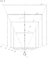
- Fig 3 is a description of a method of acquiring the drive position value obtained by driving the drive mechanism of the tracking laser distance measuring device 3 and the measured distance in the direction of the television camera in a plane in which the distance of the central axis taken by the fixed television camera is different.
- the distance A to the fixed television camera shooting range 18, the distance B from the fixed television camera shooting range 19, the distance C from the fixed television camera shooting range 20, the distance D from the fixed television camera shooting range 21, and the distance E to the fixed television camera shooting range 22 indicate the distance of the center axis taken by the fixed television camera.
- Fig 4 does not change the angle of view and the direction of view of the fixed television camera, but for each location of fixed television camera imaging ranges 23 to 27, A to E captured by a fixed television camera 1 at several different distances, the tracking laser range finder 3 causes the irradiation place of the laser beams 4 to appear at a corresponding position on the fixed television camera monitor screen 5, a method of acquiring a drive position value obtained by driving the drive mechanism and a measured distance in the direction will be described.
- Fig 5 is an explanatory diagram illustrating the distance measurement of the tracking laser distance measuring device 3 and the irradiation of laser light at a distance A from the fixed television camera 1 to the fixed television camera shooting range 18.
- the fixed television camera shooting range 23,A does not change the angle of view and the shooting direction of the fixed television camera, and the image of the fixed television camera is captured at a position on the fixed television camera monitor screen 5.
- This is a description of a method of acquiring a drive position value obtained by driving the drive mechanism for measuring the distance of the tracking laser distance measuring device 3 and measuring the measured distance in the direction.
- Fig 6 is an explanatory diagram illustrating the distance measurement of the tracking laser distance measuring device 3 and the irradiation of laser light at a distance B from the fixed television camera 1 to the fixed television camera 19 imaging range.
- the drive position value and the measured distance at all positions on the screen at the distance B to the fixed television camera shooting range 19 are calculated and interpolated at all positions on the screen by the method described with reference to fig 1 and 2 .
- Fig 7 is an explanatory diagram for measuring the distance from the fixed television camera 1 to the fixed television camera shooting range 20 and irradiating laser light for measuring the distance of the tracking laser distance measuring device 3.
- the drive position value and the measurement distance at all positions on the screen in the monitor screen of the fixed television camera imaging range 30, C are calculated and interpolated at all positions on the screen by the method described in fig 1 and 2 .
- the calculated numerical values are stored in computers 9.
- Fig 8 is an explanatory diagram for measuring the distance D from the fixed television camera 1 to the fixed television camera shooting range 21 and irradiating the laser light for measuring the distance of the tracking laser distance measuring device 3.
- the drive position value and the measurement distance at all positions on the screen in the monitor screen of the fixed television camera shooting range 31, D are calculated and interpolated by the method described with reference to fig 1 and 2 .
- the calculated numerical values are stored in computers 9.
- Fig 9 is an explanatory diagram for measuring the distance from the fixed television camera 1 to the fixed television camera shooting range 22 and irradiating the laser light for measuring the distance of the tracking laser distance measuring device 3.
- the drive position value and the measurement distance at all positions on the screen in the monitor screen of the fixed television camera imaging range 32, E are calculated and interpolated at all positions on the screen by the method described in fig 1 and 2 .
- the calculated numerical values are stored in computers 9.
- Fig 10 shows, for each distance of the central axis of the fixed television camera, described above, at a location corresponding to that of the fixed television camera imaging range 2 corresponding to all positions shown on the fixed television camera monitor screen 5, such as interpolation calculation in a two-dimensional plane to be displayed on the fixed television camera monitor screen 5, the tracking laser distance measuring machine 3 calculates and stores a drive position value for irradiating the distance meter side laser beam by an interpolation operation or the like.
- the drive value of the three-dimensional tracking laser distance measuring machine 3 at all positions shown on the fixed television camera monitor screen 5 and the measured distance of the tracking laser distance measuring machine 3 at the drive numerical value are calculated and stored in an interpolation operation or the like.
- the instruction of the fixed television camera monitor screen 5 is a two-dimensional display, but the drive position value of the tracking laser distance measuring device 3 is guided by setting the distance, and the tracking laser distance measuring device 3 is driven.
- the distance is specified, the direction is irradiated, and if there is reflected light of the tracking laser distance measuring machine 3, the distance can also be measured.
- Fig 11 illustrates the three-dimensional vertical plane described above in a three-dimensional horizontal direction.
- the position on the fixed television camera monitor screen 5 in which the fixed television camera imaging range 2 of the fixed television camera 1 is captured can be measured by the tracking laser distance measuring machine 3 at a horizontal distance from fixed television camera 1 to all positions.
- irradiation light of a tracking laser distance measuring apparatus 3 can also be taken.
- Fig 12 is an explanatory diagram for calculating an interpolation operation to be acquired by changing the imaging in the horizontal direction.
- Fig 12 is obtained by calculating the driving value and the measured distance of the tracking laser distance measuring machine 3 at all positions on the fixed television camera monitor screen 5 of the fixed television camera 1 and the tracking laser distance measuring machine 3 described above by an interpolation calculation or the like from several numerical values
- Fig 13 shows the distance value of the interpolation calculation and the drive value of the interpolation calculation by rotating the numerical control television camera 35 in the horizontal direction 45, A.
- the distance value of the interpolation calculation and the drive numerical value of the interpolation operation of the tracking laser distance measuring machine 3 described above are calculated and acquired at all positions on the numerical control television camera monitor screen 50, A in which the numerical control television camera horizontal imaging range 40, A is projected.
- the numerical control television camera is rotated in the horizontal direction 45, A, and the numerical value thereof is stored in computer 9 in the drive value of the drive mechanism.
- Fig 14 shows the distance value of the interpolation calculation and the drive value of the interpolation calculation obtained by rotating the numerical control television camera 35 in the horizontal direction 46, B.
- the distance value of the interpolation operation and the drive value of the interpolation operation of the tracking laser distance measuring machine 3 described above are calculated and acquired at all positions on the numerical control television camera monitor screen 51, B.
- the numerical control television camera is rotated in the horizontal direction 46, B and the numerical value thereof is stored in computer 9.
- Fig 15 is obtained by rotating the numerical control television camera 35 in the horizontal direction 47, C to calculate the distance value of the interpolation calculation and the drive value of the interpolation calculation.
- the distance value of the interpolation operation and the drive value of the interpolation operation of the tracking laser distance measuring machine 3 described above are calculated and acquired at all positions on the numerical control television camera monitor screen 52, C so as to project the numerical control television camera 42 horizontal shooting range C described above.
- the numerical control television camera is rotated in the horizontal direction 47, C and the numerical value thereof is stored in computer 9 in the drive value of the drive mechanism.
- a numerical control television camera 35 is rotated in the horizontal direction 48, D, and the distance value of the interpolation calculation and the drive value of the interpolation calculation are calculated and acquired.
- the distance value of the interpolation operation of the tracking laser distance measuring machine 3 and the drive value of the interpolation operation of all positions on the numerical control television camera monitor screen 53, D are calculated and acquired.
- the numerical control television camera is rotated in the horizontal direction 48, D, and the numerical value thereof is stored in computer 9 in the drive value of the drive mechanism.
- Fig 17 is obtained by rotating the numerical control television camera 35 in the horizontal direction 49, E to calculate the distance value of the interpolation calculation and the drive value of the interpolation calculation.
- the distance value of the interpolation operation of the tracking laser distance measuring machine 3 and the drive value of the interpolation operation of all positions on the numerical control television camera monitor screen 54, E are calculated and acquired.
- the numerical control television camera is rotated in the horizontal direction 49, E, and the numerical value thereof is stored in computer 9.
- Fig 18 is an explanatory diagram for calculating an interpolation operation that is acquired by changing the imaging in the vertical direction.
- Fig 18 is obtained by calculating the driving value and the measured distance of the tracking laser distance measuring machine 3 at all positions on the fixed television camera monitor screen 5 of the fixed television camera 1 and the tracking laser distance measuring machine 3 described above by interpolation calculation or the like from several numerical values
- the distance value of the interpolation calculation and the drive numerical value of the interpolation operation of the tracking laser distance measuring machine 3 described above are calculated and acquired at all positions on the numerical control television camera monitor screen 65, A.
- the numerical control television camera is rotated in the vertical direction 60, A, and the numerical value thereof is stored in computer 9.
- Fig 20 shows the distance value of the interpolation calculation and the drive value of the interpolation calculation obtained by rotating the numerical control television camera 35 in the vertical direction 61, B.
- the distance value of the interpolation operation of the tracking laser distance measuring machine 3 and the drive value of the interpolation operation of all positions on the numerical control television camera monitor screen 66-B are calculated and acquired.
- the numerical control television camera is rotated in the vertical direction 61, B, and the calculated numerical value of the drive mechanism is stored in computer 9.
- Fig 21 shows the distance value of the interpolation calculation and the drive value of the interpolation calculation obtained by rotating the numerical control television camera 35 in the 62nd vertical direction C and calculating the distance value of the interpolation calculation.
- the distance value of the interpolation operation of the tracking laser distance measuring machine 3 and the drive value of the interpolation operation of all positions on the numerical control television camera monitor screen 67, C are calculated and acquired at all positions on the numerical control television camera monitor screen 67, C, as described above.
- the numerical control television camera is rotated in the 62 vertical direction C, and the calculated numerical value of the drive mechanism is stored in computer 9.
- Fig 22 is obtained by rotating the numerical control television camera 35 in the vertical direction 63, D to calculate the distance value of the interpolation calculation and the drive value of the interpolation calculation.
- the distance value of the interpolation operation of the tracking laser distance measuring machine 3 and the drive value of the interpolation operation of all positions on the numerical control television camera monitor screen 68-D are calculated and acquired.
- the numerical control television camera is rotated in the vertical direction 63, D, and the calculated numerical value of the drive mechanism is stored in computer 9.
- the numerical control television camera 35 is rotated in the vertical direction 64, E, and the distance value of the interpolation calculation and the drive value of the interpolation operation are calculated and acquired.
- the distance value of the interpolation operation of the tracking laser distance measuring machine 3 and the drive value of the interpolation operation of all positions on the numerical control television camera monitor screen 69-E are calculated and acquired.
- the numerical control television camera is rotated in the vertical direction 64, E, and the calculated numerical value of the drive mechanism is stored in computer 9.
- Horizontal direction A to 49 horizontal directions 45-49, A to E are changed for each drive value of the numerical control television camera 35 whose imaging direction is changed, a numerical control television camera monitor screen 37is used to calculate and obtain an interpolation operation of the tracking laser distance measuring machine 3 at all positions on the numerical control television camera monitor screen, 45in all positions on the numerical control television camera monitor screen 37 in all directions in which the shooting direction is changed between the horizontal directions A to E, the interpolation operation of the tracking laser distance measuring machine 3 is calculated and acquired.
- a numerical control television camera monitor screen 37 is used to calculate and obtain an interpolation operation of the tracking laser distance measuring machine 3 at all positions on the numerical control television camera monitor screen, 60in all positions on the numerical control television camera monitor screen 37 in all directions in which the shooting direction is changed between the vertical directions A to E, the interpolation operation of the tracking laser distance measuring machine 3 is calculated and acquired.
- Fig 24 is an explanatory diagram for acquiring the drive value of the tracking laser distance measuring machine 3 at all positions on the numerical control television camera monitor screen 37 and the distance from the numerical control television camera 35 at all positions on the numerical control television camera monitor screen 37 at all positions on the numerical control television camera monitor screen 37 at all positions on the numerical control television camera monitor screen 37 at all positions on the numerical control television camera monitor screen 37.
- Fig 24 is an explanatory diagram showing a numerical control television camera shooting range of angle of view 70 to 74, A to E in which the angle of view of the angle of view of the view angle drive mechanism of the numerical control television camera 35 is changed to A-E.
- Fig 25 is an explanatory diagram for computing an interpolation operation based on all distances from the numerical control television camera to the imaging range of the numerical control television camera imaging range of the view angle 70, A of the numerical control television camera 35.
- the drive value of the tracking laser distance measuring machine 3 and the measured distance of the tracking laser distance measuring machine 3 at the driven position are acquired at all positions on the monitor screen of the numerical control television camera imaging range of the field angle 75, A taken by the numerical control television camera 35.
- the drive numerical value of the tracking laser distance measuring machine 3 at all distances from the numerical control television camera 35 and the distance from the numerical control television camera 35 at the driven location are acquired from the numerical control television camera imaging range drive values of the numerical control television camera 35.
- Fig 26 is an explanatory diagram illustrating an interpolation operation of shooting a numerical control television camera shooting range of the angle of view 71-B of the numerical control television camera 35.
- Fig 26 is an explanatory diagram for calculating an interpolation operation based on all the distances from the numerical control television camera to the imaging range of the numerical control television camera 35, which are taken at the angle of view 71-B of the numerical control television camera 35.
- the drive value of the tracking laser distance measuring machine 3 at all positions on the monitor screen of the field angle 76-B of the numerical control television camera 35 and the measured distance from the tracking laser distance measuring machine 3 at the driven place are acquired.
- the drive numerical value of the tracking laser distance measuring machine 3 at all distances from the numerical control television camera 35 and the distance from the numerical control television camera 35 at the driven position are acquired from the numerical control television camera imaging range drive values of the numerical control television camera 35.
- Fig 27 is an explanatory diagram for calculating an interpolation operation of shooting a numerical control television camera shooting range of picture angle 72, C of a numerical control television camera 35.
- Fig 27 is an explanatory diagram for calculating an interpolation operation based on all the distances from the numerical control television camera to the imaging range of the numerical control television camera 35, which are taken at the angle of view 72-C of the numerical control television camera 35.
- the drive numerical value of the tracking laser distance measuring machine 3 at all positions on the monitor screen of the view angle 77, C of the numerical control television camera 35 and the measured distance from the tracking laser distance measuring machine 3 at the driven place are acquired.
- the drive numerical value of the tracking laser distance measuring machine 3 at all distances from the numerical control television camera 35 and the distance from the numerical control television camera 35 at the driven location are acquired from the numerical control television camera imaging range drive values of the numerical control television camera 35.
- Fig 28 is an explanatory diagram for calculating an interpolation operation of shooting a numerical control television camera shooting range of the field angle 73, D of the numerical control television camera 35.
- Fig 28 is an explanatory diagram for calculating an interpolation operation based on the numerical control television camera shooting range of the field angle 73, D of the numerical control television camera 35 and all distances from the numerical control television camera to the imaging range of the numerical control television camera.
- the drive value of the tracking laser distance measuring machine 3 at all positions on the monitor screen of the view angle 78-D of the numerical control television camera 35 and the measured distance from the tracking laser distance measuring machine 3 at the driven place are acquired.
- the drive numerical value of the tracking laser distance measuring machine 3 at all distances from the numerical control television camera 35 at the angle of view 73, D of the numerical control television camera 35 and the distance from the numerical control television camera 35 at the driven position are acquired.
- Fig 29 is an explanatory diagram illustrating an interpolation operation of shooting a numerical control television camera shooting range of the field angle 74-E of the numerical control television camera 35.
- Fig 29 is an explanatory diagram for computing an interpolation operation based on the numerical control television camera imaging range of the field angle 74-E of the numerical control television camera 35 and all the distances to the imaging range of the numerical control television camera.
- the drive value of the tracking laser distance measuring machine 3 at all positions on the monitor screen of the view angle 79-E of the numerical control television camera 35 and the measured distance from the tracking laser distance measuring machine 3 at the driven place are acquired.
- the drive value of the tracking laser distance measuring machine 3 at all the distances from the numerical control television camera 35 to the numerical control television camera imaging range of the numerical control television camera 35 is acquired, and the distance from the numerical control television camera 35 at the driven position is acquired.
- the angle of view 70 of the numerical control television camera 35 for capturing the numerical control television camera shooting range of the angle 74 of view A to E is changed for each driving numerical value, the drive value of the tracking laser range finder 3 at all positions on the numerical control television camera monitor screen 37 obtained by calculating the interpolation operation from all the distances to the imaging range of the numerical control television camera, and the measured distance thereof is used, all field angles between the angle of view of the range of view angles 70 to 74 of the numerical control television cameras 35and the angle of view of the range of view angles A to E of the numerical control television camera are obtained by calculating the distance from the numerical control television camera horizontal imaging range to the numerical control television camera horizontal imaging range by interpolation or the like.
- Fig 30 is driven in conjunction with the tracking laser distance measuring machine 3 at all positions on the fixed television camera monitor screen 5 in which the screen captured by the fixed television camera is projected, a description will be given of a method in which the tracking television camera 80 captures an object in a tracking television camera monitor screen 92 and displays the subject images of the objects A84, B85, C86, D87, E88, F89, G90, and H91 of the fixed television camera imaging range 2.
- the tracking laser distance measuring machine 3 newly measures the distance in the driven direction at all positions on the fixed television camera monitor screen 5, and acquires the distance value.
- Fig 31 shows the 83 subjects A, 84 subjects B, 85 subjects C, 86 subjects D, 87 subjects E, 88 subjects F, 89 subjects G, 90 subjects H, and 91 subject I in the fixed television camera shooting range 2, 5the positions of the 93 subjects A, 94, and 95 of the fixed television camera monitor screen, the position of the 95 subject B, the position of the object C, the position of the subject D, the position of the subject G, the position of the subject H, the position of the subject H, and the position of the object I are displayed at corresponding positions.
- the position of the 93 subject A on the fixed television camera monitor screen 5 indicates the position on the screen, and the tracking laser distance measuring machine 3 is driven by the numerical value acquired by the calculation such as the interpolation calculation, and the distance of the position of the subject 83, A in the fixed television camera imaging range 2 is measured.
- the tracking television camera 80 is operated via an tracking controller 8 on a operation console 7, and the 83-object A in the fixed television camera imaging range 2 is driven by the driving mechanisms such as horizontal rotation, vertical rotation, zoom, whey, and iris of the tracking television camera 80 to perform an operation shown on a tracking television camera monitor screen 92.
- the measured distance and the drive numerical value obtained by driving the respective drive mechanisms such as horizontal rotation, vertical rotation, zoom, whey, and iris of the tracking television camera 80 are stored in the computer 9.
- subjects 84-91, B to I in the fixed television camera shooting range 2 are operated via an 8-tracking controller on a 7-operating console, and an operation shown on a tracking television camera monitor screen 92 is performed.
- the measured distance and the drive numerical value obtained by driving the respective drive mechanisms such as horizontal rotation, vertical rotation, zoom, whey, and iris of the tracking television camera 80 are stored in the computer 9.
- each distance and each drive value at the position between the positions 93-101 of the subjects A to I at the position between the positions 93-101 of the subjects A to I are interpolated by an interpolation operation or the like at a position between the positions 93-101 of the subjects A to I.
- Fig 32 shows the subject at each distance of the object distance A, 115 fixed television camera subject distance B, 116 fixed television camera subject distance D, 117 fixed television camera subject distance D, 118 fixed television camera subject distance D, 118 fixed television camera subject distance D, and 118 fixed television camera subject distance E via the 8 tracking controller, the operation is performed like a tracking television camera monitor screen 92.
- Fig 33 illustrates a case where the fixed television camera captures the same direction and captures images at the same angle of view, and the fixed television camera imaging ranges 2 are different from each other.
- the distance A shooting range 114 of the fixed television camera, the range B shooting range of the 115 fixed television camera, the distance D shooting range of the fixed television camera, the distance D shooting range of the fixed television camera, the distance D shooting range of the fixed television camera, and the distance D shooting range of the 118 fixed television camera, and the tracking television camera 80 is operated via the 8 tracking controller on a 7 console, the operation is performed like a tracking television camera monitor screen 92.
- Fig 34 is an explanatory diagram of imaging the fixed TV camera imaging range 109, A of the distance A to the subject imaging range of the 104 fixed television camera.
- the subject shown at the place corresponding to the position on the fixed television camera 1monitor screen 5 shot by the fixed television camera is related to the position of the subject on the fixed television camera monitor screen 5, a drive value obtained by driving each drive mechanism such as a horizontal rotation, a vertical rotation, a zoom, a whey, an iris, and the like of the tracking television camera 80, which has been operated to appear like a tracking television camera monitor screen 92, is associated with the distance of the object distance A of the fixed television camera 114, the data is stored in the computer 9.
- Fig 35 is an explanatory diagram of the fixed television camera imaging range A of the distance A to the subject imaging range of the fixed television camera and the fixed television camera monitor screen displaying the captured screen.
- each distance and each drive value at all positions between the positions of the subject are interpolated by an operation such as interpolation calculation from each measurement distance and each drive value stored in the computer 9.
- Fig 36 is an explanatory diagram for capturing the fixed TV camera imaging range 110, B of the distance B to the subject imaging range of the 105 fixed television camera.
- the subject shown at the location of the fixed television camera 1 imaging range 110, B corresponding to the position on the fixed television camera monitor screen 5 shot by the fixed television camera is related to the position of the subject on the fixed television camera monitor screen 5, a drive value obtained by driving each drive mechanism such as a horizontal rotation, a vertical rotation, a zoom, a whey, an iris, and the like of the tracking television camera 80, which has been operated to appear like a tracking television camera monitor screen 92, is associated with the distance between the object distance B and the object of the fixed television camera 114, the data is stored in the computer 9.
- Fig 37 is an explanatory diagram of the fixed TV camera imaging range B of the distance 110, B to the subject imaging range of the 105 fixed television camera and the fixed television camera monitor screen displaying the captured screen.
- each distance and each drive value at all positions between the positions of the subject are interpolated by an operation such as interpolation calculation from each measurement distance and each drive value stored in the computer 9.
- Fig 38 is an explanatory diagram for capturing the fixed TV camera imaging range 111, C of the distance C to the subject imaging range of the 106 fixed television camera.
- the subject shown at the location of the fixed television camera imaging range 106, C corresponding to the position on the fixed television camera monitor screen 5 shot by the fixed television camera 1 is related to the position of the subject on the fixed television camera monitor screen 5, a drive value obtained by driving each drive mechanism such as a horizontal rotation, a vertical rotation, a zoom, a whey, an iris, and the like of the tracking television camera 80, which has been operated to appear like a tracking television camera monitor screen 92, is associated with the distance between the object distance C and the object of the fixed television camera 114, the data is stored in the computer 9.
- Fig 39 is an explanatory diagram of the fixed TV camera imaging range C of the distance 111, C to the subject imaging range of the 106 fixed television camera and the fixed television camera monitor screen displaying the captured screen.
- each distance and each drive value at all positions between the positions of the subject are interpolated by an operation such as interpolation calculation from each measurement distance and each drive value stored in the computer 9.
- Fig 40 is an explanatory diagram of photographing the fixed TV camera photographing range 112, D of the distance 107, D to the object photographing range of the fixed TV camera.
- the subject shown at the location of the fixed television camera 1 imaging range 112, D corresponding to the position on the fixed television camera monitor screen 5 shot by the fixed television camera is related to the position of the subject on the fixed television camera monitor screen 5, a drive value obtained by driving each drive mechanism such as a horizontal rotation, a vertical rotation, a zoom, a whey, an iris, and the like of the tracking television camera 80, which has been operated to appear like a tracking television camera monitor screen 92, is associated with the distance between the object distance D and the object of the fixed television camera 114, the data is stored in the computer 9.
- Fig 41 is an explanatory diagram of the fixed television camera imaging range 112, D of the distance 107, D to the subject imaging range of the fixed television camera and the fixed television camera monitor screen displaying the captured screen.
- each distance and each drive value at all positions between the positions of the subject are interpolated by an operation such as interpolation calculation from each measurement distance and each drive value stored in the computer 9.
- Fig 42 is an explanatory diagram of photographing the fixed TV camera photographing range 113, E of the distance 108, E to the object photographing range of the fixed TV camera.
- the subject shown at the location of the fixed television camera imaging range 108,E corresponding to the position on the fixed television camera monitor screen 5 shot by the fixed television camera 1 is related to the position of the subject on the fixed television camera monitor screen 5, a drive value obtained by driving each drive mechanism such as a horizontal rotation, a vertical rotation, a zoom, a whey, an iris, and the like of the tracking television camera 80, which has been operated to appear like a tracking television camera monitor screen 92, is associated with the distance between the object distance E and the object of the fixed television camera 114, the data is stored in the computer 9.
- Fig 43 is an explanatory diagram of the fixed television camera imaging range 113, E of the distance 108, E to the subject imaging range of the fixed television camera and the fixed television camera monitor screen displaying the captured screen.
- each distance and each drive value at all positions between the positions of the subject are interpolated by an operation such as interpolation calculation from each measurement distance and each drive value stored in the computer 9.
- the distance and its drive values at all positions on the fixed television camera monitor screen 5 can be interpolated at all positions on the fixed television camera monitor screen 5 at all positions on the fixed television camera monitor screen 5 at all positions on the 5-fixed television camera monitor screen, and operated like the tracking television camera monitor screen 92 at all positions on the 5-fixed television camera monitor screen.
- a numerical value that can be displayed like the tracking television camera monitor screen 92 is interpolated by an arithmetic operation such as interpolation calculation at the computer 9.
- Fig 44 is an explanatory diagram of a vertical direction in which the tracking television camera captures an object in all ranges in which the fixed television camera is photographed by tracking the tracking laser rangefinder side of the tracking television camera.
- Fig 45 is an explanatory diagram of a horizontal direction in which a tracking television camera captures an object in a range to be photographed by the fixed television camera by tracking the tracking laser rangefinder side of the tracking television camera.
- Fig 46 is an explanatory diagram in which an tracking television camera 80 performs tracking shooting using a numerical value of a distance to be measured of a subject in a range captured by the numerical control television camera by tracking the tracking laser rangefinder side of the numerical control television camera.
- a horizontal rotation function of numerical control is attached to the fixed television camera described above, and the drive numerical value of the tracking photography of the tracking television camera 80 is acquired by the method described above for each horizontal rotation drive value obtained by horizontal rotation driving.
- the numerical control television camera 35 is stored in the computer 9 in association with the rotational drive value of the horizontal rotation A.
- the numerical control television camera 35 is stored in the computer 9 in association with the rotational drive value of the horizontal rotation B.
- the numerical control television camera 35 is stored in the computer 9 in association with the rotational drive value of the horizontal rotation C of the camera.
- the numerical control television camera35 is stored in the computer 9 in association with the rotational drive value of the horizontal rotation D of the camera.
- the numerical control television camera 35 is stored in a computer 9 in association with the rotation drive value of the horizontal rotation E of the numerical control television camera, and each distance and each drive value are interpolated by an operation such as interpolation calculation.
- the drive value of the tracking shooting of the tracking television camera 80 is interpolated by an operation such as interpolation calculation at the computer 9.
- Fig 52 is an explanatory diagram of tracking photographing of a tracking television camera by changing a photographing direction of a fixed television camera by changing a photographing direction of a fixed television camera by tracking a tracking laser rangefinder side of the tracking television camera 80.
- a vertical rotation function of numerical control is attached to the fixed television camera described above, and the drive numerical value of the tracking photography of the tracking television camera 80 is acquired for each vertical rotation drive value that is vertically rotated.
- the numerical control television camera 35 is stored in the computer 9 in association with the rotational drive value of the vertical rotation A.
- the numerical control television camera 35 is stored in the computer 9 in association with the rotational drive value of the vertical rotation B of the camera.
- the numerical control television camera 35 is stored in the computer 9 in association with the rotational drive value of the vertical rotation C of the camera.
- the numerical control television camera 35 is stored in the computer 9 in association with the rotational drive value of the vertical rotation D of the camera.
- the numerical control television camera 35 is stored in the computer 9 in association with the rotational drive value of the vertical rotation E of the camera.
- the drive value of the tracking shooting of the tracking television camera 80 is interpolated by an operation such as interpolation calculation at the computer 9.
- Fig 58 is an explanatory diagram of tracking shooting of the tracking television camera by changing the angle of view of the imaging of the numerical control television camera 35 without changing the direction in which the camera of the fixed television camera is captured by tracking the tracking laser rangefinder side of the tracking television camera 80.
- a zoom function of numerical control is attached to the fixed television camera described above, and the drive numerical value of the tracking photography of the tracking television camera 80 is acquired for each view angle drive position in which the angle of view of the numerical control television camera 35 is changed.
- the numerical control television camera 35 is stored in the computer 9 in association with the field angle drive value of the angle of view A of the camera.
- the drive numerical value of the tracking shooting of the tracking television camera 80 is acquired at all positions on the numerical control television camera monitor screen 37, and each distance and each drive value are interpolated by an operation such as interpolation calculation.
- the numerical control television camera 35 is stored in the computer 9 in association with the field angle drive value of the angle of view B of the camera.
- the numerical control television camera 35 is stored in the computer 9 in association with the angle of view drive value of the angle of view C of the camera.
- the numerical control television camera 35 is stored in the computer 9 in association with the field angle drive value of the angle of view D of the camera.
- the numerical control television camera 35 is stored in the computer 9 in association with the field angle drive value of the angle of view E of the camera.
- the drive value of the tracking shooting of the tracking television camera 80 associated with the angle of view of the angle of view A to E of the numerical control television camera 35 stored in the computer is interpolated by an arithmetic operation such as interpolation calculation at the computer 9.
- the distance to the subject shown in the numerical control television camera 35 is measured by the tracking laser distance measuring machine 3, and the measured distance is set in advance to the drive value of the angle of view of the numerical control television camera 35
- the angle of view of the numerical control television camera 35 is driven, and at all positions on the numerical control television camera monitor screen 82 shot at the angle of view of the drive numerical value, an tracking television camera 80 can capture an image like a tracking television camera monitor screen 92.
- Fig 64 shows the working location of a mirror tracking laser range finder 165, an tracking television camera 80, and a mirror tracking television camera 168, each driven by numerical control, 182, 183, 184 fixed television cameras 188, 189, 190 fixed television camera 1, respectively, 2, Three imaging ranges are taken.
- the image signals of the fixed television cameras 182,183 and 184 are combined on a screen by a television camera screen combiner 169 and combined into one screen and subjected to screen synthesis like a composite television monitor screen 171.
- the position of the subject 171 captured by the 173 fixed television camera 1, the position of the subject imaged by the 174 fixed television camera 2, and the irradiation position of the laser light captured by the fixed television camera 3 are numerical control devices driven by numerical control at different places.
- each drive mechanism is performed by the respective 182, 183, and 184 fixed television cameras on the composite television monitor screen 171, and the display of the synthesized television monitor screen is the same time on the television monitor screen by the operation of the numerical control mechanism.
- the work of the numerical control mechanism can be driven and operated in association with each other.
- the tracking mirror 194 accelerates the tracking speed, and is a numerical controller which is driven by numerical control of a mirror that changes the irradiation direction of laser light for distance measurement.
- the tracking mirror 194 accelerates the tracking speed, and is a numerical controller which is driven by numerical control of a mirror that changes the imaging direction of the tracking television camera.
- the present invention described above can specify the position of the subject in the three-dimensional space by measuring the position of the subject in the three-dimensional space and the distance to the subject by measuring the position of the subject in the three-dimensional space and the distance to the subject, or can be specified by a numerical value, so that each of the driving devices can be set from the outside.
- the high-speed tracking of the tracking mirror and the high image quality of the tracking television camera captured image enable a plurality of detailed image recognition, and enable tracking image recognition of a three-dimensional space close to human status determination.
Landscapes
- Engineering & Computer Science (AREA)
- Physics & Mathematics (AREA)
- General Physics & Mathematics (AREA)
- Radar, Positioning & Navigation (AREA)
- Remote Sensing (AREA)
- Computer Networks & Wireless Communication (AREA)
- Electromagnetism (AREA)
- Multimedia (AREA)
- Signal Processing (AREA)
- Theoretical Computer Science (AREA)
- Optics & Photonics (AREA)
- Computer Vision & Pattern Recognition (AREA)
- Human Computer Interaction (AREA)
- Manufacturing & Machinery (AREA)
- Automation & Control Theory (AREA)
- Health & Medical Sciences (AREA)
- General Health & Medical Sciences (AREA)
- Biomedical Technology (AREA)
- Length Measuring Devices By Optical Means (AREA)
- Optical Radar Systems And Details Thereof (AREA)
- Measurement Of Optical Distance (AREA)
Applications Claiming Priority (2)
| Application Number | Priority Date | Filing Date | Title |
|---|---|---|---|
| JP2018039078A JP6719494B2 (ja) | 2018-02-07 | 2018-02-07 | 追尾レーザー距離計測器の駆動計測で、3次元の数値駆動の制御機器の3次元の駆動数値を演算する方法。 |
| PCT/JP2019/004491 WO2019156186A2 (ja) | 2018-02-07 | 2019-02-07 | 追尾レーザー距離計測器の駆動計測で、3次元の数値駆動の制御機器の3次元の駆動数値を演算する方法。 |
Publications (2)
| Publication Number | Publication Date |
|---|---|
| EP3751313A2 true EP3751313A2 (de) | 2020-12-16 |
| EP3751313A4 EP3751313A4 (de) | 2021-10-13 |
Family
ID=67549450
Family Applications (1)
| Application Number | Title | Priority Date | Filing Date |
|---|---|---|---|
| EP19751920.0A Withdrawn EP3751313A4 (de) | 2018-02-07 | 2019-02-07 | Verfahren zur verwendung einer angesteuerten messung durch verfolgung eines laser-entfernungsmessers zur berechnung eines wertes eines dreidimensionalen antriebs für eine vorrichtung mit dreidimensionaler numerischer ansteuerung |
Country Status (6)
| Country | Link |
|---|---|
| US (1) | US12276733B2 (de) |
| EP (1) | EP3751313A4 (de) |
| JP (1) | JP6719494B2 (de) |
| KR (2) | KR20230128386A (de) |
| CN (1) | CN111699412B (de) |
| WO (1) | WO2019156186A2 (de) |
Families Citing this family (6)
| Publication number | Priority date | Publication date | Assignee | Title |
|---|---|---|---|---|
| CA3106884C (en) | 2018-07-19 | 2025-04-01 | Doosan Bobcat North America, Inc. | DISPLAY POSITION FOR CABIN WITH TILTING DOOR |
| JP2022120598A (ja) * | 2021-02-05 | 2022-08-18 | 直之 村上 | コンピユーターの目(pceye) |
| JP7575854B2 (ja) * | 2022-04-25 | 2024-10-30 | 直之 村上 | ドローンの計測飛行方法 |
| JP7702219B2 (ja) * | 2023-07-05 | 2025-07-03 | 直之 村上 | ドローンを自動離着陸する方法 |
| JP2025064653A (ja) * | 2023-10-06 | 2025-04-17 | ソニーグループ株式会社 | 情報処理装置、情報処理方法、及びプログラム |
| CN117927803A (zh) * | 2024-03-20 | 2024-04-26 | 山东省国土测绘院 | 一种地理信息测绘装置及其测绘方法 |
Family Cites Families (37)
| Publication number | Priority date | Publication date | Assignee | Title |
|---|---|---|---|---|
| JPS508308B1 (de) | 1970-02-13 | 1975-04-03 | ||
| JPS5547605U (de) | 1978-09-22 | 1980-03-28 | ||
| JPS5547670U (de) | 1978-09-26 | 1980-03-28 | ||
| JPS626115A (ja) * | 1985-07-03 | 1987-01-13 | Hitachi Ltd | 距離測定装置 |
| JPH0718700B2 (ja) * | 1988-11-10 | 1995-03-06 | 工業技術院長 | スポット光位置設定方法 |
| JPH04155211A (ja) * | 1990-10-18 | 1992-05-28 | Fujitsu Ltd | 測距方式 |
| JP2830839B2 (ja) * | 1996-05-10 | 1998-12-02 | 日本電気株式会社 | 距離計測装置 |
| JPH1188870A (ja) * | 1997-09-05 | 1999-03-30 | Tokai Rika Co Ltd | 監視システム |
| JP2001280932A (ja) * | 2000-03-31 | 2001-10-10 | Minolta Co Ltd | 撮影システム並びにそれに用いられる2次元撮像装置および3次元計測装置 |
| JP4486737B2 (ja) * | 2000-07-14 | 2010-06-23 | アジア航測株式会社 | モービルマッピング用空間情報生成装置 |
| TWI330413B (en) | 2005-01-25 | 2010-09-11 | Epistar Corp | A light-emitting device |
| CN100557384C (zh) * | 2003-11-14 | 2009-11-04 | 北京理工大学 | 一种基于双目视觉和激光测距的主动实时三维定位系统 |
| JP4533824B2 (ja) * | 2005-08-30 | 2010-09-01 | 株式会社日立製作所 | 画像入力装置及び校正方法 |
| TWI358606B (en) * | 2007-12-28 | 2012-02-21 | Ind Tech Res Inst | Method for three-dimension (3d) measurement and an |
| JP5198078B2 (ja) * | 2008-01-24 | 2013-05-15 | 株式会社日立製作所 | 計測装置および計測方法 |
| JP5322050B2 (ja) * | 2008-07-28 | 2013-10-23 | 独立行政法人日本原子力研究開発機構 | マーカの3次元位置計測方法及びシステム |
| JP5365960B2 (ja) * | 2008-10-17 | 2013-12-11 | 株式会社日立製作所 | 三次元2点間距離簡易計測装置 |
| JP5335445B2 (ja) * | 2009-01-06 | 2013-11-06 | キヤノン株式会社 | レンズ制御装置、光学機器およびレンズ制御方法 |
| DE102009023896B4 (de) * | 2009-06-04 | 2015-06-18 | Fraunhofer-Gesellschaft zur Förderung der angewandten Forschung e.V. | Vorrichtung und Verfahren zum Erfassen einer Pflanze |
| JP5624615B2 (ja) * | 2009-06-23 | 2014-11-12 | ライカ・ジオシステムズ・アクチェンゲゼルシャフトLeica Geosystems Ag | 追跡方法、および、レーザートラッカを有する測定システム |
| JP5559997B2 (ja) * | 2009-07-17 | 2014-07-23 | 株式会社トプコン | 位置測定方法及び位置測定装置 |
| JP5698480B2 (ja) | 2010-09-02 | 2015-04-08 | 株式会社トプコン | 測定方法及び測定装置 |
| JP5547605B2 (ja) * | 2010-10-22 | 2014-07-16 | 直之 村上 | 数値制御機器のテレビカメラモニター画面での操作方法 |
| CN201885693U (zh) * | 2010-12-16 | 2011-06-29 | 刘国忠 | 一种便携式三维扫描仪 |
| JP5508308B2 (ja) * | 2011-02-08 | 2014-05-28 | 直之 村上 | 数値制御機器のテレビカメラモニター画面の関連操作方法 |
| JP5547670B2 (ja) * | 2011-02-18 | 2014-07-16 | 直之 村上 | テレビカメラを取り付けた数値制御機器のテレビモニター画面の操作方法 |
| JP2013207415A (ja) * | 2012-03-27 | 2013-10-07 | Osaka City Univ | 撮像システム及び撮像方法 |
| CN103207512A (zh) * | 2012-08-21 | 2013-07-17 | 天津十彩动画科技有限公司 | 3d立体摄像机自动定位跟踪数控系统 |
| EP2765388B1 (de) * | 2013-02-08 | 2018-10-17 | Hexagon Technology Center GmbH | Mobiler Feld-Controller zur Messung und Fernsteuerung |
| KR101742632B1 (ko) * | 2013-03-08 | 2017-06-01 | 가부시키가이샤 덴소 | 이동체를 감시하는 장치 및 방법 |
| JP5902354B2 (ja) * | 2013-07-16 | 2016-04-13 | 富士フイルム株式会社 | 撮影装置及び3次元計測装置 |
| JP6208260B2 (ja) | 2013-12-26 | 2017-10-04 | 株式会社日立製作所 | 物体認識装置 |
| EP3089139A4 (de) | 2013-12-26 | 2017-06-14 | Japan Science And Technology Agency | Hilfsvorrichtung zum erlernen von bewegungen und hilfsverfahren zum erlernen von bewegungen |
| CN103884334B (zh) * | 2014-04-09 | 2016-06-01 | 中国人民解放军国防科学技术大学 | 基于宽波束激光测距和单摄像机的运动目标定位方法 |
| US10802147B2 (en) * | 2016-05-18 | 2020-10-13 | Google Llc | System and method for concurrent odometry and mapping |
| CN106125066B (zh) * | 2016-08-10 | 2018-12-07 | 北京艾沃思科技有限公司 | 激光雷达的控制系统及控制方法 |
| CN108844457B (zh) * | 2017-05-18 | 2019-05-28 | 金钱猫科技股份有限公司 | 一种精确图像测量方法及系统 |
-
2018
- 2018-02-07 JP JP2018039078A patent/JP6719494B2/ja active Active
-
2019
- 2019-02-07 WO PCT/JP2019/004491 patent/WO2019156186A2/ja not_active Ceased
- 2019-02-07 CN CN201980009000.9A patent/CN111699412B/zh not_active Expired - Fee Related
- 2019-02-07 KR KR1020237028110A patent/KR20230128386A/ko active Pending
- 2019-02-07 KR KR1020207025837A patent/KR20200125626A/ko not_active Ceased
- 2019-02-07 EP EP19751920.0A patent/EP3751313A4/de not_active Withdrawn
-
2020
- 2020-08-07 US US16/988,580 patent/US12276733B2/en active Active
Also Published As
| Publication number | Publication date |
|---|---|
| US20200371244A1 (en) | 2020-11-26 |
| EP3751313A4 (de) | 2021-10-13 |
| CN111699412B (zh) | 2024-05-31 |
| JP6719494B2 (ja) | 2020-07-08 |
| CN111699412A (zh) | 2020-09-22 |
| WO2019156186A2 (ja) | 2019-08-15 |
| KR20200125626A (ko) | 2020-11-04 |
| WO2019156186A3 (ja) | 2019-10-10 |
| JP2019138889A (ja) | 2019-08-22 |
| US12276733B2 (en) | 2025-04-15 |
| KR20230128386A (ko) | 2023-09-04 |
Similar Documents
| Publication | Publication Date | Title |
|---|---|---|
| US12276733B2 (en) | Method of computing three-dimensional drive parameter of a three-dimensional numerical drive control device by driving measurement of a tracking laser distance meter | |
| JP7300948B2 (ja) | 測量データ処理装置、測量データ処理方法、測量データ処理用プログラム | |
| KR101204486B1 (ko) | 피측정물의 검사 측정 장치 | |
| JP5263804B2 (ja) | 多点測定方法及び測量装置 | |
| US8363152B2 (en) | Method for focusing the shooting lens of a motion picture or video camera | |
| EP3421930A1 (de) | System zur erzeugung von dreidimensionalen formdaten und texturinformationen, fotografiesteuerungsprogramm und verfahren zur erzeugung von dreidimensionalen formdaten und texturinformationen | |
| JP2016057063A (ja) | 測定対象物の非接触検知方法及びその装置 | |
| JP2019100995A (ja) | 測量画像表示制御装置、測量画像表示制御方法および測量画像表示制御用プログラム | |
| JP2022500793A (ja) | 多自由度可動視覚システムのキャリブレーション方法 | |
| KR101204870B1 (ko) | 감시 카메라 시스템 및 그의 제어방법 | |
| JP6174199B1 (ja) | 誘導方法及び画像表示システム | |
| CN116297531B (zh) | 机器视觉检测方法、系统、介质及设备 | |
| JP2830839B2 (ja) | 距離計測装置 | |
| US9225894B2 (en) | Method and device for focusing a film camera | |
| JP2021527217A (ja) | 干渉測定装置のビーム配向ユニットのためのアラインメント方法及びレーザ照射を用いて干渉測定を実施するための測定装置 | |
| JPH05196432A (ja) | 三次元座標計測装置 | |
| JPWO2020075213A1 (ja) | 計測装置、計測方法および顕微鏡システム | |
| JP2002318344A (ja) | 光学機器のオートフォーカシング方法および装置 | |
| JPH0617795B2 (ja) | 三次元位置計測装置 | |
| Wang et al. | A high-speed stereo monitoring system for remote one-man operation | |
| JP3906512B2 (ja) | 自動追尾照明装置 | |
| KR101714700B1 (ko) | 스캔 데이터 정합 장치 | |
| KR20200082441A (ko) | 촬영영상을 이용한 실내공간 실측 시스템 | |
| JPH09304814A (ja) | 作業機械の操作支援画像システム | |
| JPH0371043B2 (de) |
Legal Events
| Date | Code | Title | Description |
|---|---|---|---|
| STAA | Information on the status of an ep patent application or granted ep patent |
Free format text: STATUS: THE INTERNATIONAL PUBLICATION HAS BEEN MADE |
|
| PUAI | Public reference made under article 153(3) epc to a published international application that has entered the european phase |
Free format text: ORIGINAL CODE: 0009012 |
|
| STAA | Information on the status of an ep patent application or granted ep patent |
Free format text: STATUS: REQUEST FOR EXAMINATION WAS MADE |
|
| 17P | Request for examination filed |
Effective date: 20200907 |
|
| AK | Designated contracting states |
Kind code of ref document: A2 Designated state(s): AL AT BE BG CH CY CZ DE DK EE ES FI FR GB GR HR HU IE IS IT LI LT LU LV MC MK MT NL NO PL PT RO RS SE SI SK SM TR |
|
| AX | Request for extension of the european patent |
Extension state: BA ME |
|
| DAV | Request for validation of the european patent (deleted) | ||
| DAX | Request for extension of the european patent (deleted) | ||
| A4 | Supplementary search report drawn up and despatched |
Effective date: 20210910 |
|
| RIC1 | Information provided on ipc code assigned before grant |
Ipc: G01S 7/51 20060101ALI20210906BHEP Ipc: H04N 5/225 20060101ALI20210906BHEP Ipc: G01S 17/86 20200101ALI20210906BHEP Ipc: G01S 17/08 20060101ALI20210906BHEP Ipc: G01C 3/06 20060101ALI20210906BHEP Ipc: G01S 17/66 20060101AFI20210906BHEP |
|
| STAA | Information on the status of an ep patent application or granted ep patent |
Free format text: STATUS: EXAMINATION IS IN PROGRESS |
|
| 17Q | First examination report despatched |
Effective date: 20240301 |
|
| STAA | Information on the status of an ep patent application or granted ep patent |
Free format text: STATUS: THE APPLICATION IS DEEMED TO BE WITHDRAWN |
|
| 18D | Application deemed to be withdrawn |
Effective date: 20250902 |