EP3750758A1 - Fahrzeuginnenraumstruktur - Google Patents
Fahrzeuginnenraumstruktur Download PDFInfo
- Publication number
- EP3750758A1 EP3750758A1 EP19760684.1A EP19760684A EP3750758A1 EP 3750758 A1 EP3750758 A1 EP 3750758A1 EP 19760684 A EP19760684 A EP 19760684A EP 3750758 A1 EP3750758 A1 EP 3750758A1
- Authority
- EP
- European Patent Office
- Prior art keywords
- cone
- shaped portion
- vehicle interior
- interior structure
- disposed
- Prior art date
- Legal status (The legal status is an assumption and is not a legal conclusion. Google has not performed a legal analysis and makes no representation as to the accuracy of the status listed.)
- Withdrawn
Links
Images


Classifications
-
- B—PERFORMING OPERATIONS; TRANSPORTING
- B60—VEHICLES IN GENERAL
- B60R—VEHICLES, VEHICLE FITTINGS, OR VEHICLE PARTS, NOT OTHERWISE PROVIDED FOR
- B60R13/00—Elements for body-finishing, identifying, or decorating; Arrangements or adaptations for advertising purposes
- B60R13/02—Internal Trim mouldings ; Internal Ledges; Wall liners for passenger compartments; Roof liners
- B60R13/0212—Roof or head liners
-
- B—PERFORMING OPERATIONS; TRANSPORTING
- B60—VEHICLES IN GENERAL
- B60R—VEHICLES, VEHICLE FITTINGS, OR VEHICLE PARTS, NOT OTHERWISE PROVIDED FOR
- B60R21/00—Arrangements or fittings on vehicles for protecting or preventing injuries to occupants or pedestrians in case of accidents or other traffic risks
- B60R21/02—Occupant safety arrangements or fittings, e.g. crash pads
- B60R21/04—Padded linings for the vehicle interior ; Energy absorbing structures associated with padded or non-padded linings
-
- B—PERFORMING OPERATIONS; TRANSPORTING
- B62—LAND VEHICLES FOR TRAVELLING OTHERWISE THAN ON RAILS
- B62D—MOTOR VEHICLES; TRAILERS
- B62D25/00—Superstructure or monocoque structure sub-units; Parts or details thereof not otherwise provided for
- B62D25/06—Fixed roofs
-
- B—PERFORMING OPERATIONS; TRANSPORTING
- B60—VEHICLES IN GENERAL
- B60R—VEHICLES, VEHICLE FITTINGS, OR VEHICLE PARTS, NOT OTHERWISE PROVIDED FOR
- B60R13/00—Elements for body-finishing, identifying, or decorating; Arrangements or adaptations for advertising purposes
- B60R13/02—Internal Trim mouldings ; Internal Ledges; Wall liners for passenger compartments; Roof liners
- B60R13/0206—Arrangements of fasteners and clips specially adapted for attaching inner vehicle liners or mouldings
-
- B—PERFORMING OPERATIONS; TRANSPORTING
- B60—VEHICLES IN GENERAL
- B60R—VEHICLES, VEHICLE FITTINGS, OR VEHICLE PARTS, NOT OTHERWISE PROVIDED FOR
- B60R21/00—Arrangements or fittings on vehicles for protecting or preventing injuries to occupants or pedestrians in case of accidents or other traffic risks
- B60R21/02—Occupant safety arrangements or fittings, e.g. crash pads
- B60R21/04—Padded linings for the vehicle interior ; Energy absorbing structures associated with padded or non-padded linings
- B60R2021/0414—Padded linings for the vehicle interior ; Energy absorbing structures associated with padded or non-padded linings using energy absorbing ribs
-
- B—PERFORMING OPERATIONS; TRANSPORTING
- B60—VEHICLES IN GENERAL
- B60R—VEHICLES, VEHICLE FITTINGS, OR VEHICLE PARTS, NOT OTHERWISE PROVIDED FOR
- B60R21/00—Arrangements or fittings on vehicles for protecting or preventing injuries to occupants or pedestrians in case of accidents or other traffic risks
- B60R21/02—Occupant safety arrangements or fittings, e.g. crash pads
- B60R21/04—Padded linings for the vehicle interior ; Energy absorbing structures associated with padded or non-padded linings
- B60R2021/0435—Padded linings for the vehicle interior ; Energy absorbing structures associated with padded or non-padded linings associated with the side or roof pillars
-
- B—PERFORMING OPERATIONS; TRANSPORTING
- B60—VEHICLES IN GENERAL
- B60R—VEHICLES, VEHICLE FITTINGS, OR VEHICLE PARTS, NOT OTHERWISE PROVIDED FOR
- B60R21/00—Arrangements or fittings on vehicles for protecting or preventing injuries to occupants or pedestrians in case of accidents or other traffic risks
- B60R21/02—Occupant safety arrangements or fittings, e.g. crash pads
- B60R21/04—Padded linings for the vehicle interior ; Energy absorbing structures associated with padded or non-padded linings
- B60R2021/0442—Padded linings for the vehicle interior ; Energy absorbing structures associated with padded or non-padded linings associated with the roof panel
-
- B—PERFORMING OPERATIONS; TRANSPORTING
- B60—VEHICLES IN GENERAL
- B60R—VEHICLES, VEHICLE FITTINGS, OR VEHICLE PARTS, NOT OTHERWISE PROVIDED FOR
- B60R21/00—Arrangements or fittings on vehicles for protecting or preventing injuries to occupants or pedestrians in case of accidents or other traffic risks
- B60R21/02—Occupant safety arrangements or fittings, e.g. crash pads
- B60R21/04—Padded linings for the vehicle interior ; Energy absorbing structures associated with padded or non-padded linings
- B60R21/0428—Padded linings for the vehicle interior ; Energy absorbing structures associated with padded or non-padded linings associated with the side doors or panels, e.g. displaced towards the occupants in case of a side collision
Definitions
- the present disclosure relates to a vehicle interior structure.
- Patent Document 1 discloses an impact absorbing member with a lattice-shaped rib structure.
- Patent Document 1 Japanese Unexamined Patent Publication No. 2002-225658
- the present disclosure is made in consideration of the above circumstances, and it is an object of the present disclosure to provide a vehicle interior structure including an impact absorbing member disposed between a roof panel and a top ceiling to allow the impact absorbing member to absorb a heavy load by even a small amount of vertical displacement.
- a first aspect of the disclosure relates to a vehicle interior structure including an impact absorbing member disposed between a roof panel and a top ceiling disposed below the roof panel, the impact absorbing member including a base plate portion and a hollow, cone-shaped portion extending upward from the base plate portion, the cone-shaped portion having a fragile portion that facilitates vertical crush and deformation.
- the fragile portion is configured as a vertically extending opening formed in a side surface of the cone-shaped portion (a second aspect).
- a specific structure of the fragile portion is provided.
- configuring the fragile portion as an opening makes it possible to simply and reliably form the fragile portion, and further, setting the size of the opening makes it possible to easily obtain desired load-deformation characteristics of the cone-shaped portion.
- a lower end of the opening reaches the base plate portion (a third aspect). This case is preferable for sufficiently crushing and deforming the cone-shaped portion to allow the cone-shaped portion to sufficiently absorb a load.
- the opening includes a plurality of openings formed along a circumference of the cone-shaped portion at equal intervals (a fourth aspect). This case is preferable for substantially uniformly crushing and deforming the cone-shaped portion along its circumference.
- the plurality of openings include two openings formed along the circumference of the cone-shaped portion at 180-degree intervals (a fifth aspect). This case makes it possible to crush and deform the cone-shaped portion to allow the cone-shaped portion to spread in a direction perpendicular to a line connecting two openings together.
- a reinforcement is disposed directly under the roof panel and extends in a vehicle width direction, and the cone-shaped portion is disposed between the reinforcement and the top ceiling (a sixth aspect).
- a heavy load tends to be applied from the reinforcement.
- the cone-shaped portion can effectively absorb such a load from the reinforcement.
- the vertical interval between the reinforcement and the top ceiling is extremely small, but the cone-shaped portion can absorb a heavy load within such a small vertical interval range.
- the base plate portion includes a rib for impact absorption at a position displaced from the reinforcement in a longitudinal direction (a seventh aspect).
- the impact can be absorbed by the rib, too.
- the cone-shaped portion includes a plurality of cone-shaped portions disposed between the reinforcement and the top ceiling and spaced apart from each other in a longitudinal direction (an eighth aspect).
- the plurality of cone-shaped portions can more effectively absorb an impact.
- the reinforcement has a cross-section such that a projection projecting upward is continuous with a recess recessed upward in a longitudinal direction, and the cone-shaped portion is disposed in the projection projecting upward (a ninth aspect).
- a ninth aspect it is possible to dispose the cone-shaped portion in the space between the reinforcement and the top ceiling at a position where the vertical interval is larger.
- the fragile portion is configured as a vertically extending opening formed in a side surface of the cone-shaped portion, the opening includes two openings formed along the circumference of the cone-shaped portion at 180-degree intervals, and the cone-shaped portion disposed in the projection is formed such that the two openings are spaced apart from each other in a longitudinal direction (a tenth aspect).
- the cone-shaped portions which are to be crushed and deformed so as to spread in the vehicle width direction relative to a longitudinally extending line connecting the two openings together, can be smoothly crushed and deformed without interference of a vertical wall of the reinforcement. This is preferable for allowing the cone-shaped portions to effectively absorb a load.
- the cone-shaped portion has a flat upper surface (an eleventh aspect). This case, with the flat surface defined as a region to which a load from the roof panel to the cone-shaped portion is applied, is preferable for effectively transferring the load from the roof panel to the cone-shaped portion.
- the impact absorbing member is disposed in the roof panel in a longitudinal direction at a region corresponding to a B-pillar (a twelfth aspect).
- the region corresponding to a B-pillar in the roof panel in a longitudinal direction is high in rigidity and is high in effectiveness of a load transfer from the roof panel. Therefore, disposing the cone-shaped portion at such a region is preferable for allowing the cone-shaped portion to effectively absorb an impact.
- the impact absorbing member including the base plate portion and the cone-shaped portion is a one-piece molding of synthetic resin (a thirteenth aspect). This case is preferable for simply forming the impact absorbing member with a lighter weight. In addition, even if the head of an occupant who has stood up inside the vehicle is abut against the impact absorbing member through the top ceiling, this case is also preferable for alleviating the impact to the head.
- an impact absorbing member disposed between a roof panel and a top ceiling can absorb a heavy load by even a small amount of vertical displacement.
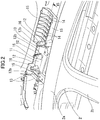
- reference character 1 denotes a roof panel and reference character 2 denotes a side panel.
- the side panel 2 is frame-shaped with a front-rear pair of openings 3A and 3B for doors.
- a portion continuous with the roof panel 1 is a roof side rail 2a, and a portion extending downward from an intermediate position of the roof side rail 2a in a longitudinal direction is a B-pillar 2b.
- an impact absorbing member 10 is disposed directly under the roof panel 1. More specifically, the position where the impact absorbing member 10 is disposed relative to the roof panel 1 corresponds to the position of the B-pillar 2b in the longitudinal direction, and is immediately adjacent to the B-pillar 2b in a vehicle width direction.
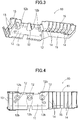
- the overall shape of the impact absorbing member 10 is illustrated in FIGS. 3 and 4 .
- the impact absorbing member 10 is a one-piece molding of synthetic resin.
- the impact absorbing member 10 has a base plate portion 11 that is long in the longitudinal direction. From the base plate portion 11, a plurality of cone-shaped portions 12, a plurality of front ribs 13, and a plurality of rear ribs 14 each extend upward. The plurality of cone-shaped portions 12 (three in the embodiment) are spaced apart from each other in the longitudinal direction.
- the front ribs 13 extend in the vehicle width direction, and are formed in front of the cone-shaped portions 12.
- the rear ribs 14 extend in the vehicle width direction, and are formed behind the cone-shaped portions 12.
- the plurality of front ribs 13 are formed to be spaced apart from each other in the longitudinal direction.
- the plurality of rear ribs 14 are formed to be spaced apart from each other in the longitudinal direction.
- the number of the rear ribs 14 is greater than that of the front ribs 13.
- a left-right pair of vertical walls 15 (can be said to be ribs extending in the longitudinal direction) extends upward in a position associated with the rear ribs 14, the vertical walls 15 being spaced apart from each other in the vehicle width direction.
- the rear ribs 14 extend in the vehicle width direction to couple the left-right pair of vertical walls 15 together.
- the rear ribs 14 has an intermediate portion in the vehicle width direction ("a widthwise intermediate portion") and an end in the vehicle width direction (“a widthwise end”) such that the widthwise intermediate portion is higher than the vertical wall 15 and the widthwise end is at almost the same height as the vertical wall 15.
- the front rib 13 has a similar configuration to the rear rib 14, but does not have the outward one of the left-right pair of vertical walls 15 in the vehicle width direction.
- FIG. 5 illustrates how the impact absorbing member 10 is disposed relative to the roof panel 1.
- reference character 20 denotes a top ceiling
- reference character 30 denotes a reinforcement.
- the top ceiling 20 substantially constitutes a ceiling wall of a vehicle interior and is made of a soft material.
- the reinforcement 30 has respective widthwise ends bonded to an associated one of the roof side rails 2a, and spaced apart from (the lower surface of) the roof panel 1.
- the reinforcement 30 has a cross-section such that a projection ⁇ projecting upward is continuous with a recess ⁇ recessed downward.
- reference character 30a denotes a top wall
- reference character 30b denotes a bottom wall
- reference character 30c denotes a vertical wall extending vertically and having ends which are one end of the top wall 30a and one end of the bottom wall 30b.
- only one projection ⁇ is provided in the intermediate position in the longitudinal direction, and a front-rear pair of recesses ⁇ is provided so as to sandwich the projection ⁇ in the longitudinal direction.
- the reinforcement 30 has ends in the longitudinal direction ("longitudinal ends"), each of which is a flange 30d positioned at substantially the same height as the top wall 30a.
- Each of the longitudinal ends of the reinforcement 30 is open frontward or rearward. That is to say, no vertical wall 30c is provided to each of the longitudinal ends of the reinforcement 30.
- FIGS. 6 and 7 illustrate the cone-shaped portion 12, specifically.
- the cone-shaped portion 12 is in the shape of a hollow cone (truncated cone) with a flat upper surface 12a. Further, the cone-shaped portion 12 has a side surface provided with two openings 12b formed along its circumference at 180-degree intervals. This opening 12b serves as a fragile portion, and the lower end thereof reaches the base plate portion 11. The upper end of the opening 12b, though not reaching the upper surface 12a, is adjacent to the upper surface 12a.
- Three cone-shaped portions 12 are disposed between the reinforcement 30 and the top ceiling 20. Specifically, the middle cone-shaped portion 12 in the longitudinal direction is disposed under the projection ⁇ of the reinforcement 30, and the rest cone-shaped portions 12 adjacent to respective longitudinal ends are disposed under the flange 30d formed at respective longitudinal ends of the reinforcement 30.
- FIG. 8 shows load-deformation characteristics of the respective cone-shaped portions 12.
- the vertical axis of represents an axial load to be absorbed by the cone-shaped portion 12
- the horizontal axis represents an axial deformation volume in applying each load relative to the initial state (a state where no load is applied) of the cone-shaped portion 12.
- use of a small amount of displacement in the cone-shaped portion 12 makes it possible to absorb a heavy load (even a small amount of vertical displacement enables absorption of the heavy load).
- Changing the thickness of the cone-shaped portions 12 and the length and width of the opening 12b enables achievement of desired load-deformation characteristics of the cone-shaped portions 12.
- the position of one pair of the openings 12b formed in the cone-shaped portion 12 differs between the cone-shaped portion 12 at the longitudinal intermediate position and the cone-shaped portions 12 at the longitudinal ends.
- the two openings 12b of the cone-shaped portion 12 at the longitudinal intermediate position are provided so as to be spaced apart from each other in the longitudinal direction.
- the two openings 12b of each of the cone-shaped portions 12 at the longitudinal ends are provided so as to be spaced apart from each other in the vehicle width direction.
- the cone-shaped portion 12 when receiving a vertical load, is crushed and deformed so as to be divided at the two openings 12b (is crushed and deformed so as to spread in a direction perpendicular to a line connecting two openings 12b together).
- the cone-shaped portion 12 at the longitudinal intermediate position is crushed and deformed so as to spread in the vehicle width direction, and thus, the cone-shaped portion 12 can sufficiently be crushed and deformed without interference (interruption) of the front-rear pair of the vertical walls 30c of the reinforcement 30.
- the cone-shaped portions 12 at the longitudinal ends are crushed and deformed so as to spread in the longitudinal direction.
- at least the frontward or rearward portion thereof is sufficiently open (that is, one longitudinal end is provided with no vertical wall 30c of the reinforcement 30), thereby reliably enabling crush and deformation to spread in the longitudinal direction.
- the impact absorbing member 10 is fixed to the upper surface of the top ceiling 20 with, e.g., a hot-melt, a double-sided tape or an adhesive. Further, the upper surface 12a of the cone-shaped portion 12 and the vicinity thereof are covered with a cushioning material 16 (to prevent direct contact between the cone-shaped portion 12 and the reinforcement 30). It is to be noted that the cushioning material 16 is illustrated in FIG. 2 , but is not illustrated in FIGS. 3 and 4 .
- the impact absorbing member 10 including the cone-shaped portions 12 can be disposed in the roof panel 1 at a proper region that is required to absorb an impact (for example, at front and rear edges of the roof panel 1).
- the number of the cone-shaped portions 12 to be provided to the base plate portion is selectable as appropriate (one, two, or four or more cone-shaped portions 12 are provided).
- the opening 12b formed in the cone-shaped portions 12 and serving as a fragile portion can be set as appropriate.
- three or more opening 12b can also be arranged along the circumference of the cone-shaped portion 12 at equal intervals, or the opening 12b can be extended along the circumference to provide the plurality of the openings 12b in the vertical direction.
- the shape of the fragile portion formed in the cone-shaped portion 12 is not limited to the opening, and proper shapes such as a linear shape, or recess (thin portion) shape can be adopted.
- the cone-shaped portion 12 is in the shape of the cone with the flat upper surface.
- a polygon pyramid such as a hexagonal pyramid or octagonal pyramid, with a flat upper surface can also be used.
- the present disclosure effectively absorbs an impact of a load from a roof panel, and is preferable for safety guarantee.
Applications Claiming Priority (2)
| Application Number | Priority Date | Filing Date | Title |
|---|---|---|---|
| JP2018036438A JP7169529B2 (ja) | 2018-03-01 | 2018-03-01 | 車両用内装構造 |
| PCT/JP2019/006636 WO2019167807A1 (ja) | 2018-03-01 | 2019-02-21 | 車両用内装構造 |
Publications (2)
| Publication Number | Publication Date |
|---|---|
| EP3750758A4 EP3750758A4 (de) | 2020-12-16 |
| EP3750758A1 true EP3750758A1 (de) | 2020-12-16 |
Family
ID=67804995
Family Applications (1)
| Application Number | Title | Priority Date | Filing Date |
|---|---|---|---|
| EP19760684.1A Withdrawn EP3750758A1 (de) | 2018-03-01 | 2019-02-21 | Fahrzeuginnenraumstruktur |
Country Status (5)
| Country | Link |
|---|---|
| US (1) | US11505135B2 (de) |
| EP (1) | EP3750758A1 (de) |
| JP (1) | JP7169529B2 (de) |
| CN (1) | CN111788091B (de) |
| WO (1) | WO2019167807A1 (de) |
Families Citing this family (2)
| Publication number | Priority date | Publication date | Assignee | Title |
|---|---|---|---|---|
| WO2020100961A1 (ja) | 2018-11-16 | 2020-05-22 | 日本電気株式会社 | 負荷軽減装置、負荷軽減方法、及びプログラムを記憶する記憶媒体 |
| US11760418B2 (en) | 2021-07-06 | 2023-09-19 | Ford Global Technologies, Llc | Energy absorber between vehicle roof and headliner |
Family Cites Families (31)
| Publication number | Priority date | Publication date | Assignee | Title |
|---|---|---|---|---|
| DE3412846A1 (de) * | 1984-04-05 | 1985-10-17 | Hoechst Ag, 6230 Frankfurt | Flaechenfoermiger sandwichformkoerper |
| JP3121652B2 (ja) * | 1991-12-26 | 2001-01-09 | 積水化学工業株式会社 | 自動車用天井材 |
| US6752450B2 (en) * | 1998-02-04 | 2004-06-22 | Oakwood Energy Management, Inc. | Formed energy absorber |
| US6682128B2 (en) * | 1998-02-04 | 2004-01-27 | Oakwood Energy Management, Inc. | Composite energy absorber |
| US7625023B2 (en) * | 2000-02-07 | 2009-12-01 | Oakwood Energy Management, Inc. | Modular energy absorber with ribbed wall structure |
| US7404593B2 (en) * | 2000-02-07 | 2008-07-29 | Oakwood Energy Management Inc. | Modular energy absorber of varying topography and method for configuring same |
| JP3941398B2 (ja) | 2001-02-01 | 2007-07-04 | マツダ株式会社 | 車両の内装材構造 |
| US20020142129A1 (en) * | 2001-02-21 | 2002-10-03 | Hutsman Corporation | Automotive head impact protection |
| US6474724B2 (en) * | 2001-03-26 | 2002-11-05 | Daimlerchrysler Corporation | Vehicle pillar having an interior protuberance at the roof headliner |
| EP1544051B1 (de) * | 2003-12-19 | 2006-08-09 | Grupo Antolin Ingenieria, S.A. | Modulare Struktur zur Energieaufnahme beim Kopfaufprall auf Fahrzeuginnenteile |
| US7338038B2 (en) * | 2004-03-12 | 2008-03-04 | Dow Global Technologies, Inc. | Impact absorption structure |
| JP4531468B2 (ja) * | 2004-07-14 | 2010-08-25 | 小島プレス工業株式会社 | 車両用衝撃吸収構造体及びその取付構造 |
| JP4548207B2 (ja) | 2005-04-28 | 2010-09-22 | スズキ株式会社 | 車両ルーフ部における緩衝部材取付構造 |
| JP2006347273A (ja) | 2005-06-14 | 2006-12-28 | Kasai Kogyo Co Ltd | 自動車用内装部品及びその製造方法 |
| JP4688661B2 (ja) * | 2005-12-09 | 2011-05-25 | 株式会社イノアックコーポレーション | 車両用衝撃吸収部材 |
| JP2008114734A (ja) * | 2006-11-06 | 2008-05-22 | Mazda Motor Corp | 衝撃吸収部材を備えた車両の室内構造 |
| JP2009196629A (ja) | 2008-01-21 | 2009-09-03 | Hayashi Engineering Inc | 車両用衝撃吸収構造体 |
| KR100897334B1 (ko) * | 2008-04-30 | 2009-05-15 | 현대자동차주식회사 | 충격 흡수판 |
| US7758107B2 (en) * | 2008-07-29 | 2010-07-20 | Ford Global Technologies, Llc | Dual cell body side rail for automotive vehicles |
| JP2010052533A (ja) * | 2008-08-27 | 2010-03-11 | Hayashi Engineering Inc | 車両用衝撃吸収体 |
| US9644699B2 (en) * | 2009-03-30 | 2017-05-09 | Oakwood Energy Management, Inc. | Energy absorber with anti-BSR accessory |
| CN102405153B (zh) * | 2009-04-21 | 2014-04-09 | 本田技研工业株式会社 | 车辆用乘员保护装置 |
| JP4448938B1 (ja) * | 2009-05-22 | 2010-04-14 | 株式会社ホワイトインパクト | 樹脂シートの成形品 |
| JP5316566B2 (ja) | 2011-02-25 | 2013-10-16 | マツダ株式会社 | 車両の上部構造 |
| US8641137B2 (en) * | 2012-04-30 | 2014-02-04 | Nissan North America, Inc. | Vehicle headliner assembly |
| US9279258B2 (en) * | 2013-04-18 | 2016-03-08 | Viconic Defense Inc. | Recoiling energy absorbing system with lateral stabilizer |
| US9169977B2 (en) * | 2013-06-28 | 2015-10-27 | Cree, Inc. | LED lamp |
| KR101546922B1 (ko) | 2014-04-25 | 2015-08-25 | (주)대한솔루션 | 자동차용 헤드라이닝의 충격흡수 보조 부재 |
| DE102014218730A1 (de) * | 2014-09-18 | 2016-03-24 | Ford Global Technologies, Llc | Energieabsorber und Überkopfsystem mit Energieabsorber |
| JP2016124458A (ja) * | 2015-01-06 | 2016-07-11 | 三和工業株式会社 | 車両ルーフパネル用の積層成形体及びその製造方法 |
| US11130392B2 (en) * | 2019-05-20 | 2021-09-28 | Toyota Motor Engineering & Manufacturing North America, Inc. | Door service hole cover |
-
2018
- 2018-03-01 JP JP2018036438A patent/JP7169529B2/ja active Active
-
2019
- 2019-02-21 WO PCT/JP2019/006636 patent/WO2019167807A1/ja unknown
- 2019-02-21 CN CN201980016199.8A patent/CN111788091B/zh active Active
- 2019-02-21 EP EP19760684.1A patent/EP3750758A1/de not_active Withdrawn
- 2019-02-21 US US16/976,050 patent/US11505135B2/en active Active
Also Published As
| Publication number | Publication date |
|---|---|
| JP2019151162A (ja) | 2019-09-12 |
| US11505135B2 (en) | 2022-11-22 |
| CN111788091A (zh) | 2020-10-16 |
| WO2019167807A1 (ja) | 2019-09-06 |
| EP3750758A4 (de) | 2020-12-16 |
| US20200398902A1 (en) | 2020-12-24 |
| CN111788091B (zh) | 2023-02-28 |
| JP7169529B2 (ja) | 2022-11-11 |
Similar Documents
| Publication | Publication Date | Title |
|---|---|---|
| US8152218B2 (en) | Integral pelvic impact energy-absorbing pre-crush protective construction for vehicle door | |
| JP2002362273A (ja) | 衝撃吸収装置 | |
| US6264238B1 (en) | Reactive surface rib cartridge countermeasure for vehicle interior hard trim applications | |
| US11505135B2 (en) | Vehicle interior structure | |
| JP2006199173A (ja) | 車体構造 | |
| US10093158B2 (en) | Supplemental load transfer trim system | |
| US9522646B2 (en) | Knee bolster | |
| JP2016117344A (ja) | 車両用センタピラー | |
| US20100171337A1 (en) | Map pocket close-out as integrated pelvic bolster for vehicle door | |
| JP6706718B2 (ja) | 車両用内装部材 | |
| JP2017136995A (ja) | 車両用内装部品 | |
| US20090045613A1 (en) | Energy management system | |
| JP2018134890A (ja) | 車両用衝撃吸収構造 | |
| JP2019026163A (ja) | 衝撃吸収体 | |
| US9517742B2 (en) | Shock absorber member for vehicle, vehicle door panel assembly including shock absorber member and vehicle including door panel assembly | |
| US10479308B2 (en) | Damping member for vehicle | |
| CN103909872B (zh) | 车辆用收纳结构 | |
| JP7358954B2 (ja) | 衝撃吸収材の取付構造 | |
| CN106143386B (zh) | 车内顶棚吸能结构、车辆顶棚以及车辆 | |
| KR101496466B1 (ko) | 자동차범퍼용 백빔 장치 | |
| KR19990021417U (ko) | 자동차의 센터플로어 보강구조 | |
| KR100307096B1 (ko) | 충격흡수능력이 향상된 차량용 필라트림구조 | |
| KR200211073Y1 (ko) | 자동차의 사이드실 구조 | |
| KR100889227B1 (ko) | 자동차 도어용 충격흡수부재 | |
| KR19980076099A (ko) | 강성을 보강한 리어범퍼 |
Legal Events
| Date | Code | Title | Description |
|---|---|---|---|
| STAA | Information on the status of an ep patent application or granted ep patent |
Free format text: STATUS: THE INTERNATIONAL PUBLICATION HAS BEEN MADE |
|
| PUAI | Public reference made under article 153(3) epc to a published international application that has entered the european phase |
Free format text: ORIGINAL CODE: 0009012 |
|
| STAA | Information on the status of an ep patent application or granted ep patent |
Free format text: STATUS: REQUEST FOR EXAMINATION WAS MADE |
|
| 17P | Request for examination filed |
Effective date: 20200911 |
|
| A4 | Supplementary search report drawn up and despatched |
Effective date: 20201118 |
|
| AK | Designated contracting states |
Kind code of ref document: A1 Designated state(s): AL AT BE BG CH CY CZ DE DK EE ES FI FR GB GR HR HU IE IS IT LI LT LU LV MC MK MT NL NO PL PT RO RS SE SI SK SM TR |
|
| AX | Request for extension of the european patent |
Extension state: BA ME |
|
| RIC1 | Information provided on ipc code assigned before grant |
Ipc: B62D 25/06 20060101ALI20201126BHEP Ipc: B60R 21/04 20060101AFI20201126BHEP Ipc: B60R 13/02 20060101ALI20201126BHEP |
|
| STAA | Information on the status of an ep patent application or granted ep patent |
Free format text: STATUS: THE APPLICATION HAS BEEN WITHDRAWN |
|
| DAV | Request for validation of the european patent (deleted) | ||
| DAX | Request for extension of the european patent (deleted) | ||
| 18W | Application withdrawn |
Effective date: 20210519 |