EP3733274B1 - Materialeinspritzplanungsverfahren zur herstellung eines vorläufers mit konzentrationsgradient - Google Patents
Materialeinspritzplanungsverfahren zur herstellung eines vorläufers mit konzentrationsgradient Download PDFInfo
- Publication number
- EP3733274B1 EP3733274B1 EP18894714.7A EP18894714A EP3733274B1 EP 3733274 B1 EP3733274 B1 EP 3733274B1 EP 18894714 A EP18894714 A EP 18894714A EP 3733274 B1 EP3733274 B1 EP 3733274B1
- Authority
- EP
- European Patent Office
- Prior art keywords
- feed tank
- feed
- flow rate
- feeding
- mixer
- Prior art date
- Legal status (The legal status is an assumption and is not a legal conclusion. Google has not performed a legal analysis and makes no representation as to the accuracy of the status listed.)
- Active
Links
Images


Classifications
-
- H—ELECTRICITY
- H01—ELECTRIC ELEMENTS
- H01M—PROCESSES OR MEANS, e.g. BATTERIES, FOR THE DIRECT CONVERSION OF CHEMICAL ENERGY INTO ELECTRICAL ENERGY
- H01M4/00—Electrodes
- H01M4/02—Electrodes composed of, or comprising, active material
- H01M4/13—Electrodes for accumulators with non-aqueous electrolyte, e.g. for lithium-accumulators; Processes of manufacture thereof
- H01M4/134—Electrodes based on metals, Si or alloys
-
- B—PERFORMING OPERATIONS; TRANSPORTING
- B01—PHYSICAL OR CHEMICAL PROCESSES OR APPARATUS IN GENERAL
- B01J—CHEMICAL OR PHYSICAL PROCESSES, e.g. CATALYSIS OR COLLOID CHEMISTRY; THEIR RELEVANT APPARATUS
- B01J19/00—Chemical, physical or physico-chemical processes in general; Their relevant apparatus
- B01J19/0053—Details of the reactor
- B01J19/0066—Stirrers
-
- B—PERFORMING OPERATIONS; TRANSPORTING
- B01—PHYSICAL OR CHEMICAL PROCESSES OR APPARATUS IN GENERAL
- B01J—CHEMICAL OR PHYSICAL PROCESSES, e.g. CATALYSIS OR COLLOID CHEMISTRY; THEIR RELEVANT APPARATUS
- B01J4/00—Feed or outlet devices; Feed or outlet control devices
- B01J4/008—Feed or outlet control devices
-
- B—PERFORMING OPERATIONS; TRANSPORTING
- B01—PHYSICAL OR CHEMICAL PROCESSES OR APPARATUS IN GENERAL
- B01J—CHEMICAL OR PHYSICAL PROCESSES, e.g. CATALYSIS OR COLLOID CHEMISTRY; THEIR RELEVANT APPARATUS
- B01J4/00—Feed or outlet devices; Feed or outlet control devices
- B01J4/02—Feed or outlet devices; Feed or outlet control devices for feeding measured, i.e. prescribed quantities of reagents
-
- H—ELECTRICITY
- H01—ELECTRIC ELEMENTS
- H01M—PROCESSES OR MEANS, e.g. BATTERIES, FOR THE DIRECT CONVERSION OF CHEMICAL ENERGY INTO ELECTRICAL ENERGY
- H01M10/00—Secondary cells; Manufacture thereof
- H01M10/04—Construction or manufacture in general
- H01M10/0404—Machines for assembling batteries
-
- H—ELECTRICITY
- H01—ELECTRIC ELEMENTS
- H01M—PROCESSES OR MEANS, e.g. BATTERIES, FOR THE DIRECT CONVERSION OF CHEMICAL ENERGY INTO ELECTRICAL ENERGY
- H01M10/00—Secondary cells; Manufacture thereof
- H01M10/05—Accumulators with non-aqueous electrolyte
- H01M10/054—Accumulators with insertion or intercalation of metals other than lithium, e.g. with magnesium or aluminium
-
- H—ELECTRICITY
- H01—ELECTRIC ELEMENTS
- H01M—PROCESSES OR MEANS, e.g. BATTERIES, FOR THE DIRECT CONVERSION OF CHEMICAL ENERGY INTO ELECTRICAL ENERGY
- H01M10/00—Secondary cells; Manufacture thereof
- H01M10/05—Accumulators with non-aqueous electrolyte
- H01M10/058—Construction or manufacture
-
- H—ELECTRICITY
- H01—ELECTRIC ELEMENTS
- H01M—PROCESSES OR MEANS, e.g. BATTERIES, FOR THE DIRECT CONVERSION OF CHEMICAL ENERGY INTO ELECTRICAL ENERGY
- H01M4/00—Electrodes
- H01M4/02—Electrodes composed of, or comprising, active material
- H01M4/13—Electrodes for accumulators with non-aqueous electrolyte, e.g. for lithium-accumulators; Processes of manufacture thereof
- H01M4/139—Processes of manufacture
- H01M4/1395—Processes of manufacture of electrodes based on metals, Si or alloys
-
- H—ELECTRICITY
- H01—ELECTRIC ELEMENTS
- H01M—PROCESSES OR MEANS, e.g. BATTERIES, FOR THE DIRECT CONVERSION OF CHEMICAL ENERGY INTO ELECTRICAL ENERGY
- H01M4/00—Electrodes
- H01M4/02—Electrodes composed of, or comprising, active material
- H01M4/13—Electrodes for accumulators with non-aqueous electrolyte, e.g. for lithium-accumulators; Processes of manufacture thereof
- H01M4/131—Electrodes based on mixed oxides or hydroxides, or on mixtures of oxides or hydroxides, e.g. LiCoOx
-
- H—ELECTRICITY
- H01—ELECTRIC ELEMENTS
- H01M—PROCESSES OR MEANS, e.g. BATTERIES, FOR THE DIRECT CONVERSION OF CHEMICAL ENERGY INTO ELECTRICAL ENERGY
- H01M4/00—Electrodes
- H01M4/02—Electrodes composed of, or comprising, active material
- H01M4/36—Selection of substances as active materials, active masses, active liquids
- H01M4/362—Composites
-
- H—ELECTRICITY
- H01—ELECTRIC ELEMENTS
- H01M—PROCESSES OR MEANS, e.g. BATTERIES, FOR THE DIRECT CONVERSION OF CHEMICAL ENERGY INTO ELECTRICAL ENERGY
- H01M4/00—Electrodes
- H01M4/02—Electrodes composed of, or comprising, active material
- H01M4/36—Selection of substances as active materials, active masses, active liquids
- H01M4/48—Selection of substances as active materials, active masses, active liquids of inorganic oxides or hydroxides
- H01M4/50—Selection of substances as active materials, active masses, active liquids of inorganic oxides or hydroxides of manganese
- H01M4/505—Selection of substances as active materials, active masses, active liquids of inorganic oxides or hydroxides of manganese of mixed oxides or hydroxides containing manganese for inserting or intercalating light metals, e.g. LiMn2O4 or LiMn2OxFy
-
- H—ELECTRICITY
- H01—ELECTRIC ELEMENTS
- H01M—PROCESSES OR MEANS, e.g. BATTERIES, FOR THE DIRECT CONVERSION OF CHEMICAL ENERGY INTO ELECTRICAL ENERGY
- H01M4/00—Electrodes
- H01M4/02—Electrodes composed of, or comprising, active material
- H01M4/36—Selection of substances as active materials, active masses, active liquids
- H01M4/48—Selection of substances as active materials, active masses, active liquids of inorganic oxides or hydroxides
- H01M4/52—Selection of substances as active materials, active masses, active liquids of inorganic oxides or hydroxides of nickel, cobalt or iron
- H01M4/525—Selection of substances as active materials, active masses, active liquids of inorganic oxides or hydroxides of nickel, cobalt or iron of mixed oxides or hydroxides containing iron, cobalt or nickel for inserting or intercalating light metals, e.g. LiNiO2, LiCoO2 or LiCoOxFy
-
- Y—GENERAL TAGGING OF NEW TECHNOLOGICAL DEVELOPMENTS; GENERAL TAGGING OF CROSS-SECTIONAL TECHNOLOGIES SPANNING OVER SEVERAL SECTIONS OF THE IPC; TECHNICAL SUBJECTS COVERED BY FORMER USPC CROSS-REFERENCE ART COLLECTIONS [XRACs] AND DIGESTS
- Y02—TECHNOLOGIES OR APPLICATIONS FOR MITIGATION OR ADAPTATION AGAINST CLIMATE CHANGE
- Y02P—CLIMATE CHANGE MITIGATION TECHNOLOGIES IN THE PRODUCTION OR PROCESSING OF GOODS
- Y02P70/00—Climate change mitigation technologies in the production process for final industrial or consumer products
- Y02P70/50—Manufacturing or production processes characterised by the final manufactured product
Definitions
- the present invention relates to a material injection scheduling method for producing a precursor having a concentration gradient, and more particularly, to a material injection scheduling method for producing a precursor having a concentration gradient in which two materials are mixed with each other in advance using a mixer and injected into a reactor.
- a rechargeable lithium secondary battery has a significantly higher energy density than a conventional battery, but has a disadvantage in that a thermal property is poor due to an unstable crystal structure of a cathode active material at a high temperature. Therefore, as a method for solving such a disadvantage, a method for producing a precursor whose metal composition has a concentration gradient has been studied.
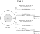
- the precursor having the concentration gradient refers to a precursor in which a core portion is formed of a material having the same composition ratio, and a shell portion is formed so that a composition ratio gradually changes radially.
- metal solutions having different composition ratios are injected from a Q1 feed tank to a Q2 feed tank, the metal solutions are continuously injected from the Q1 feed tank to the Q2 feed tank at a fixed constant flow rate during a reaction time, and the entire metal solutions mixed within a given reaction time are injected from the Q2 feed tank to a reactor, such that the concentration gradient is adjusted.
- the present invention has been made in an effort to provide a material injection scheduling method having advantages of producing a precursor having a uniform concentration gradient.
- step 8 substituting each time values making a difference in the feed flow rate of the material of the first feed tank constant; (d) a step of correcting the feed flow rate of the material of the first feed tank by calculating a difference between the injection amount and the flow rate of the first feed tank for each time calculated in step (b), and the values of the difference are arranged to time in reverse order to be subtracted from the injection amount calculated in step (c); and (e) a step of calculating a feed flow rate of the material of the second feed tank by subtracting the feed flow rate of the material of the first feed tank corrected in the step (d) from the feed flow rate of the mixer.
- the material injection scheduling method may further include, between the step (a) and the step (b), (f) a step of calculating a time taken for feeding the entire material of the first feed tank in consideration of an amount of the material of the first feed tank injected into the mixer in advance.
- the material injection scheduling method may further include, between the step (b) and the step (c), (e) a step of determining whether or not the difference in the feed flow rate of the material of the first feed tank is the same between feeding steps other than between a first feeding step and a second feeding step and between a last feeding step and a feeding step just before the last feeding step.
- step (e) If it is determined in the step (e) that the difference in the feed flow rate of the material of the first feed tank is not the same between feeding steps other than between the first feeding step and the second feeding step and between the last feeding step and the feeding step just before the last feeding step, the step (b) may be performed again.
- the material injection scheduling method may further include, between the step (e) and the step (c), (f) a step of summing the feed flow rates of the material of the first feed tank in all feeding steps; and (g) a step of determining whether or not a sum of the feed flow rates of the material of the first feed tank is greater than a total amount of the material to be injected from the first feed tank into the mixer.
- the step (c) is not performed and the pattern calculated in the step (b) may be determined to be an injection schedule of the material of the first feed tank, and if the sum of the feed flow rates of the material of the first feed tank is greater than the total amount of the material to be injected from the first feed tank into the mixer in the step (g), the step (c) may be performed.
- the material injection scheduling method may further include, between the step (d) and the step (e), (h) a step of determining whether or not a difference between the sum of the feed flow rates of the material of the first feed tank and the total amount of the material to be injected from the first feed tank into the mixer is a predetermined value or less.
- step (c) and the step (d) may be performed again.
- the material of the first feed tank may be a mixed solution of nickel and cobalt
- the material of the second feed tank may be a mixed solution of nickel, cobalt, and manganese.
- a precursor having a uniform concentration gradient may be produced even though a reaction time is changed, such that the quality of the precursor may be improved, and preliminary verification for the concentration gradient may be performed, such that a variation in precursor quality may be minimized.
- FIG. 3 is a conceptual diagram illustrating an apparatus for producing a precursor having a concentration gradient.
- FIG. 4 is a graph illustrating an injection amount of a material depending on a reaction time ideal for the apparatus for producing a precursor having a concentration gradient.
- FIG. 5 is a graph illustrating an injection amount of a material depending on a reaction time ideal for the apparatus for producing a precursor.
- FIG. 6 is a graph illustrating an injection amount of a material depending on a reaction time when a feed amount of a material of a Q1 feed tank is simply calculated in a pattern in which it gradually decreases during a total process time.
- the apparatus for producing a precursor having a concentration gradient includes two feed tanks Q1 and Q2 storing metal solutions having different composition ratios, a plurality of mixers Q3 mixing the metal solutions having different composition ratios injected from the two feed tanks Q1 and Q2, and a plurality of reactors A, B, C, and D connected to the plurality of mixers Q3 in a one-to-one corresponding manner and receiving the mixed metal solutions from the mixer Q3.
- the mixer Q3 and the reactors A, B, C, and D are illustrated as four, respectively, but the number of them may be increased or decreased as necessary.
- the metal solutions having different composition ratios injected from the two feed tanks Q1 and Q2 are mixed in the mixer Q3 in advance and then injected into the reactors A, B, C and D to perform the process.
- a production capacity may be effectively increased or decreased only with the increase or decrease in the number of the mixer Q3 and the reactors A, B, C and D.
- an injection amount of the mixed materials injected from the mixer Q3 into the reactors A, B, C, and D is constant, but in the feed flow rate injected from the two feed tanks Q1 and Q2 into the mixer Q3, the injection amount is required to be sequentially changed in a opposite pattern to each other in order to create a concentration gradient.
- FIG. 4 is a graph showing the most ideal schedule of the feed flow rate injected from the two feed tanks Q1 and Q2 to the mixer Q3.
- the reaction starts in a state in which the metal solution of the first feed tank Q1 is filled at a predetermined amount (500 kg in the embodiment) in advance.
- the injection amount of the material of the first feed tank Q1 is 500 kg or less than that of a second feed tank Q2, and after all the materials contained in the first feed tank Q1 are consumed, 500 kg of the material contained in the mixer Q3 is injected into the reactor.
- a graph for material feeding as shown in FIG. 5 , is to be created.
- a core portion of the precursor has a constant composition, without change in the composition, and a shell portion thereof has a specific slope for the change in concentration for each metal solution.
- the injection amount of the material of the first feed tank Q1 is calculated to be in a pattern that it gradually decreases for a total reaction time.
- FIG. 6 shows a material injection schedule for 30-hour reaction, and the feed flow rate from the mixer Q3 into the reactors A, B, C, and D is fixed at 221.77 kg/h.
- the injection amount of the core composition solution is to be decreased by a constant flow rate difference.
- the flow rate of the core composition solution to be injected for 1 hour in the second injection step is calculated by using the feed flow rate per hour of the mixer Q3, 221.77kg/h, and an injection amount of the core composition solution obtained by subtracting 500 kg injected into the mixer Q3 in advance from the total amount of the core composition solution (an amount of the material injected from the first feed tank Q1) as a basis for the calculation.
- the feed flow rate per hour of the mixer Q3, 221.77kg/h is an amount calculated based on the total amount of the core composition solution, not based on the amount of the material injected from the first feed tank Q1.
- a degree of decrease in the flow rate of the core composition solution injected for 2 hours may be calculated to be large compared to a degree of decrease in the flow rate of the core composition solution after 2 hours.
- Table 1 shows the detailed values of the flow rate for the injection schedule up to the initial 6 hours in FIG. 6 .
- Injection time (Hour) Gradient Difference Final injection amount of core Q1 Q2 Q3 1 29.51 221.77 0 221.77 2 7.80 192.26 29.51 221.77 3 7.80 184.46 37.31 221.77 4 7.80 176.65 45.11 221.77 5 7.80 168.85 52.92 221.77 6 7.80 161.04 60.72 221.77 7 7.80 153.24 68.53 221.77
- the difference between the first injection flow rate and the second injection flow rate is 29.51 kg/h, and after the second flow rate, it constantly decrease at a slope of 7.80 kg/h.
- this rapid change in the first injection flow rate and the second injection flow rate causes the concentration of the portion in contact with the core of the precursor to change rapidly compared to that of other portions.
- the following material injection scheduling method is provided.
- FIG. 7 is a flow chart of a material injection scheduling method for producing a precursor having a concentration gradient according to an exemplary embodiment of the present invention.
- FIG. 8 is a graph illustrating a process of modifying an injection schedule of a feed amount of a material of a Q1 feed tank through the material injection scheduling method for producing a precursor having a concentration gradient according to an exemplary embodiment of the present invention.
- the feed flow rate of Q3 is calculated by dividing the sum of the total amount of the material of Q1 and the total amount of the material of Q2 by the total process time (Tr) (S2).
- the time (TQ1) required for feeding the entire materials of the Q1 feed tank is calculated by subtracting the time required to consume the material of Q1 stored in Q3 in advance from the total process time (Tr) (value obtained by dividing the amount of the material of Q1 stored in Q3 in advance by the feed flow rate of Q3) (S3).
- the flow rate of the material to be fed from the Q1 feed tank into the Q3 feed tank is calculated in a pattern in which it gradually decreases (S4).
- the flow rate of Q1 (FQ1t) for each time (for feeding step) is calculated using Equation 2 below.
- FQ1t 2 ⁇ (total amount of material of Q1-amount of material of Q1 sotred in Q3 in advance-amount of material of Q1 injected in advance)/(time required for feeding entire materials of Q1 feed tank(TQ1)-time already taken for injection into Q1
- the change in the flow rate of the material to be fed from the Q1 feed tank into the Q3 calculated through the above process may be represented as S4 in the graph of FIG. 8 .
- step (S4) is performed again, and if it is determined to be ⁇ YES', the material injection scheduling method proceeds to next step (S6).
- step (S4) the flow rate of Q1 (FQ1t) for each time (for each feeding step) calculated in step (S4) is summed (S6).
- step (S6) it is determined whether or not the sum of the flow rate of Q1 (FQ1t) calculated in step (S6) is greater than the total amount of feeding of Q1 (total amount of material of Q1 - amount of material of Q1 stored in Q3 in advance) (S7).
- the flow rate of Q1 (FQ1t) calculated in step (S6) is determined as a feeding schedule of Q1 and the material injection scheduling method proceeds to step (S11), and if it is determined to be ⁇ YES', the material injection scheduling method proceeds to step (S8).
- a difference between the optimum amount calculated in step (S8) and the flow rate of Q1 (FQ1t) for each time (for each feeding step) calculated in step (S4) is calculated, and the values of the difference are arranged to feeding step in reverse order to be subtracted from the optimum amount calculated in step (S8), such that a corrected flow rate of Q1 in each feeding step is obtained (S9).
- the corrected flow rate of Q1 in each feeding step may be represented as S9 in the graph of FIG. 8 .
- step (S10) it is determined whether or not the value obtained by subtracting the total amount of feeding of Q1 from the sum of the corrected flow rates of Q1 in each feeding step is smaller than a predetermined value set in advance (S10).
- steps (S8 and S9) are performed again, and if it is determined to be ⁇ YES', the corrected flow rate of Q1 is determined as the feeding schedule of Q1 and the material injection scheduling method proceeds to step (S11).
- the feed flow rate of Q2 is calculated by subtracting the feed schedule of Q1 determined in step S10 from the feed flow rate of Q3 (S11).
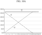
- FIG. 9A , FIG. 10A , and FIG. 11A show the results obtained by calculating the material injection schedule of the co-precipitation process with reaction times of 22 hours, 25 hours, and 30 hours, respectively, according to an embodiment of the present invention.
- FIG. 9B , FIG. 10B , and FIG. 11B when the schedule obtained through the material injection scheduling method according to the embodiment of the present invention is used, a precursor may be formed to have a uniform concentration gradient even in the vicinity of the core.
Landscapes
- Chemical & Material Sciences (AREA)
- Chemical Kinetics & Catalysis (AREA)
- Engineering & Computer Science (AREA)
- Electrochemistry (AREA)
- General Chemical & Material Sciences (AREA)
- Organic Chemistry (AREA)
- Manufacturing & Machinery (AREA)
- Materials Engineering (AREA)
- Battery Electrode And Active Subsutance (AREA)
- Inorganic Compounds Of Heavy Metals (AREA)
- Physical Or Chemical Processes And Apparatus (AREA)
- Carbon Steel Or Casting Steel Manufacturing (AREA)
- Control Of Non-Electrical Variables (AREA)
Claims (9)
- Materialinjektionsplanungsverfahren zur Herstellung eines Vorläufers mit einem Konzentrationsgradienten unter Verwendung einer Vorrichtung zur Herstellung eines Vorläufers mit einem Konzentrationsgradienten, die Materialien eines ersten Zulauftanks (Q1) und eines zweiten Zulauftanks (Q2) vorab in einem Mischer (Q3) miteinander mischt und das gemischte Material in einen Reaktor einspritzt, wobei das Verfahren Folgendes umfasst:(a) einen Schritt zum Berechnen einer Zulaufdurchflussrate des Mischers (Q3) durch Teilen einer Summe einer Gesamtmenge des Materials des ersten Zulauftanks (Q1) und einer Gesamtmenge des Materials des zweiten Zulauftanks (Q2) durch eine Gesamtprozesszeit (Tr) ;(b) einen Schritt zum Berechnen einer Zulaufdurchflussrate des Materials des ersten Zulauftanks (Q1) während der gesamten Prozesszeit (Tr) in einem Muster, in dem sie für jedes Mal allmählich abnimmt, unter Verwendung der folgenden Gleichung 2:
eine Durchflussrate (FQ1t) des ersten Zulauftanks (Q1) für jeden Zeitpunkt = 2 x vorab im Mischer (Q3) gespeicherte (Gesamtmaterialmenge des ersten Zulauftanks (Q1) - Materialmenge des ersten Zulauftanks (Q1)- vorab eingespritzte Materialmenge des ersten Zulauftanks (Q1) / (Zeit (TQ1), die zum Zuführen der gesamten Materialien des ersten Zulauftanks (Q1) benötigt wird - bereits benötigte Zeit für die Einspritzung in den ersten Zulauftank (Q1)) (c) einen Schritt zum Berechnen einer Einspritzmenge durch Erstellen einer Gleichung, die eine lineare Gleichung darstellt (S8), wie in Fig. 8 gezeigt, und zum Ersetzen jedes Mal durch Werte, die eine Differenz in der Zulaufdurchflussrate des Materials des ersten Zulauftanks (Q1) konstant machen;(d) einen Schritt zum Korrigieren der Zulaufdurchflussrate des Materials des ersten Zulauftanks (Q1) durch Berechnen einer Differenz zwischen der Einspritzmenge und der Durchflussrate (FQ1t) des ersten Zulauftanks (Q1) für jeden in Schritt (b) berechneten Zeitpunkt, und die Werte der Differenz zeitlich in umgekehrter Reihenfolge angeordnet werden, um von der in Schritt (c) berechneten Einspritzmenge subtrahiert zu werden; und(e) einen Schritt zum Berechnen einer Zulaufdurchflussrate des Materials des zweiten Zulauftanks (Q2) durch Subtrahieren der in Schritt (d) korrigierten Zulaufdurchflussrate des Materials des ersten Zulauftanks (Q1) von der Zulaufströmung Geschwindigkeit des Mischers (Q3). - Verfahren nach Anspruch 1, weiterhin umfassend zwischen Schritt (a) und Schritt (b),
(f) einen Schritt zum Berechnen einer Zeit, die zum Zuführen des gesamten Materials des ersten Zulauftanks (Q1) benötigt wird, unter Berücksichtigung einer Menge des Materials des ersten Zulauftanks (Ql), die im Voraus in den Mischer (Q3) eingespritzt wurde. - Verfahren nach Anspruch 2, weiterhin umfassend zwischen dem (b) Schritt und dem
Schritt (c),
(e) einen Schritt zum Bestimmen, ob die Differenz in der Zulaufdurchflussrate des Materials des ersten Zulauftanks (Q1) zwischen den Zulaufschritten gleich ist oder nicht, außer zwischen einem ersten Zulaufschritt und einem zweiten Zulaufschritt und zwischen einem letzten Zulaufschritt und einem Zulaufschritt direkt vor dem letzten Zulaufschritt. - Verfahren nach Anspruch 3, wobei: wenn in Schritt (e) bestimmt wird, dass die Differenz in der Zulaufdurchflussrate des Materials des ersten Zulauftanks (Q1) zwischen Zulaufschritten, außer zwischen dem ersten Zulaufschritt und dem zweiten Zulaufschritt und zwischen dem letzten Zulaufschritt und dem Zulaufschritt unmittelbar vor dem letzten Zulaufschritt, nicht gleich ist, der Schritt (b) erneut durchgeführt wird.
- Verfahren nach Anspruch 4, weiterhin umfassend zwischen Schritt (e) und Schritt (c):(f) einen Schritt zum Summieren der Zulaufdurchflussraten des Materials des ersten Zulauftanks (Q1) in allen Zulaufschritten; und(g) einen Schritt zum Bestimmen, ob eine Summe der Zulaufdurchflussraten des Materials des ersten Zulauftanks (Q1) größer als eine Gesamtmenge des aus dem ersten Zulauftank (Q1) in den Mixer (Q3) einzuspritzenden Materials ist oder nicht.
- Verfahren nach Anspruch 5, wobei: wenn die Summe der Fördermengen des Materials des ersten Fördertanks (Q1) nicht größer ist als die Gesamtmenge des im Schritt (g) aus dem ersten Fördertank (Q1) in den Mixer (Q3) einzuspritzenden Materials, der Schritt (c) nicht durchgeführt wird und das im Schritt (b) berechnete Muster als Einspritzplan des Materials des ersten Zulauftanks (Q1) bestimmt wird, und wenn die Summe der Zulaufdurchflussraten des Materials des ersten Zulauftanks (Q1) größer ist als die Gesamtmenge des Materials, das im Schritt (g) aus dem ersten Zulauftank (Q1) in den Mixer (Q3) eingespritzt werden soll, der Schritt (c) durchgeführt wird.
- Verfahren nach Anspruch 6, ferner umfassend zwischen Schritt (d) und Schritt (e) (h) einen Schritt zum Bestimmen, ob eine Differenz zwischen der Summe der Zulaufdurchflussraten des Materials des ersten Zulauftanks (Q1) besteht oder nicht, und die Gesamtmenge des vom ersten Zulauftank (Q1) in den Mischer (Q3) einzuspritzenden Materials einen vorgegebenen Wert oder weniger beträgt.
- Verfahren nach Anspruch 7, wobei: wenn die Differenz zwischen der Summe der Fördermengen des Materials des ersten Fördertanks (Q1) und der Gesamtmenge des vom ersten Zulauftank (Q1) in den Mischer (Q3) einzuspritzenden Materials im Schritt (h) nicht dem vorgegebenen Wert entspricht oder darunter liegt, Schritt (c) und Schritt (d) erneut durchgeführt werden.
- Verfahren nach Anspruch 1, wobei: das Material des ersten Zulauftanks (Q1) eine Mischlösung aus Nickel und Kobalt ist und das Material des zweiten Zulauftanks (Q2) eine gemischte Lösung aus Nickel, Kobalt und Mangan ist.
Applications Claiming Priority (2)
| Application Number | Priority Date | Filing Date | Title |
|---|---|---|---|
| KR1020170180061A KR102008875B1 (ko) | 2017-12-26 | 2017-12-26 | 농도 구배 전구체의 제조 장치 및 그 재료 투입 스케줄링 방법 |
| PCT/KR2018/015779 WO2019132331A1 (ko) | 2017-12-26 | 2018-12-12 | .농도 구배 전구체의 제조 장치 및 그 재료 투입 스케줄링 방법 |
Publications (4)
| Publication Number | Publication Date |
|---|---|
| EP3733274A1 EP3733274A1 (de) | 2020-11-04 |
| EP3733274A4 EP3733274A4 (de) | 2021-03-03 |
| EP3733274B1 true EP3733274B1 (de) | 2024-08-07 |
| EP3733274B8 EP3733274B8 (de) | 2024-09-18 |
Family
ID=67067720
Family Applications (1)
| Application Number | Title | Priority Date | Filing Date |
|---|---|---|---|
| EP18894714.7A Active EP3733274B8 (de) | 2017-12-26 | 2018-12-12 | Materialeinspritzplanungsverfahren zur herstellung eines vorläufers mit konzentrationsgradient |
Country Status (7)
| Country | Link |
|---|---|
| US (1) | US12255310B2 (de) |
| EP (1) | EP3733274B8 (de) |
| JP (1) | JP7062768B2 (de) |
| KR (1) | KR102008875B1 (de) |
| CN (1) | CN111683743B (de) |
| PL (1) | PL3733274T3 (de) |
| WO (1) | WO2019132331A1 (de) |
Families Citing this family (3)
| Publication number | Priority date | Publication date | Assignee | Title |
|---|---|---|---|---|
| KR102008875B1 (ko) | 2017-12-26 | 2019-08-08 | 주식회사 포스코 | 농도 구배 전구체의 제조 장치 및 그 재료 투입 스케줄링 방법 |
| KR20220159228A (ko) | 2021-05-25 | 2022-12-02 | (주)에코프로머티리얼즈 | 복수의 반응기를 포함하는 리튬 이온 이차전지의 양극활물질 전구체 제조장치, 및 이로부터 제조된 리튬 이온 이차전지 양극활물질 전구체 |
| KR20260005468A (ko) * | 2024-07-03 | 2026-01-12 | 고려아연 주식회사 | 양극 활물질 전구체의 제조 방법 |
Family Cites Families (25)
| Publication number | Priority date | Publication date | Assignee | Title |
|---|---|---|---|---|
| JP4752135B2 (ja) | 2001-05-25 | 2011-08-17 | 株式会社Gsユアサ | リチウム電池 |
| GB2410741A (en) * | 2004-02-07 | 2005-08-10 | Phoenix Chemicals Ltd | Making chloramine |
| DE102006055218A1 (de) * | 2006-11-21 | 2008-05-29 | Bayer Technology Services Gmbh | Kontinuierliches Verfahren zur Synthese von nanoskaligen metallhaltigen Nanopartikel und Nanopartikeldispersion |
| DE102008029804A1 (de) | 2008-06-24 | 2010-07-08 | Süd-Chemie AG | Mischoxid enthaltend einen Lithium-Mangan-Spinell und Verfahren zu dessen Herstellung |
| KR101185366B1 (ko) * | 2010-01-14 | 2012-09-24 | 주식회사 에코프로 | 회분식 반응기(batch reactor)를 사용하여 농도구배층을 가지는 리튬 이차 전지용 양극활물질 전구체 및 양극활물질을 제조하는 방법 |
| KR101292756B1 (ko) | 2011-01-05 | 2013-08-02 | 한양대학교 산학협력단 | 입자 전체 농도 구배 리튬이차전지용 양극활물질, 이의 제조 방법, 및 이를 포함하는 리튬이차전지 |
| US9281515B2 (en) | 2011-03-08 | 2016-03-08 | Gholam-Abbas Nazri | Lithium battery with silicon-based anode and silicate-based cathode |
| KR101948177B1 (ko) | 2011-08-12 | 2019-02-14 | 어플라이드 머티어리얼스, 인코포레이티드 | 입자 합성 장치 및 방법들 |
| KR101521178B1 (ko) | 2012-03-31 | 2015-05-19 | 한양대학교 산학협력단 | 리튬 이차 전지용 양극활물질 전구체의 제조 방법, 이에 의하여 제조된 리튬 이차 전지용 양극활물질 전구체, 및 이를 포함하는 리튬 이차 전지용 양극활물질 |
| KR101565298B1 (ko) * | 2012-11-27 | 2015-11-03 | 주식회사 엘지화학 | 무기화합물의 제조장치 및 이를 사용한 무기화합물의 제조방법 |
| KR101596272B1 (ko) * | 2013-01-03 | 2016-02-22 | 주식회사 엘지화학 | 리튬 복합 전이금속 산화물 제조용 장치, 이를 이용하여 제조된 리튬 복합 전이금속 산화물, 및 그 제조방법 |
| WO2014180719A1 (de) * | 2013-05-08 | 2014-11-13 | Basf Se | Sphärische partikel, ihre herstellung und verwendung |
| US10069144B2 (en) * | 2013-05-08 | 2018-09-04 | Basf Se | Spherical particles, production and use thereof |
| CN105378985B (zh) | 2013-05-31 | 2019-03-01 | 汉阳大学校产学协力团 | 锂电池用正极活性物质及其制造方法 |
| CN104347866B (zh) * | 2013-07-26 | 2016-12-28 | 比亚迪股份有限公司 | 一种锂电池正极材料及其制备方法 |
| KR101692826B1 (ko) | 2014-06-10 | 2017-01-17 | 주식회사 엘지화학 | 표면 개질된 양극 활물질 및 이를 제조하는 방법 |
| KR101702572B1 (ko) | 2014-08-22 | 2017-02-13 | 주식회사 포스코이에스엠 | 무코발트 농도 구배 양극활물질의 제조 방법 및 이에 의하여 제조된 무코발트 농도 구배 양극활물질 |
| KR20160077388A (ko) * | 2014-12-22 | 2016-07-04 | 주식회사 포스코 | 리튬 이차 전지용 전구체 제조를 위한 반응기 |
| KR101953155B1 (ko) | 2014-12-31 | 2019-02-28 | 주식회사 에코프로비엠 | 농도 구배를 나타내는 리튬 이차전지용 양극활물질 전구체 및 양극활물질을 제조하는 방법, 및 이에 의하여 제조된 농도 구배를 나타내는 리튬 이차전지용 양극활물질 전구체 및 양극활물질 |
| CN204429248U (zh) * | 2014-12-31 | 2015-07-01 | 山东玉皇新能源科技有限公司 | 用于合成梯度三元材料的加料系统 |
| KR101760490B1 (ko) * | 2015-12-17 | 2017-07-21 | 주식회사 포스코 | 전구체 제조 장치와 제조방법 |
| KR101897232B1 (ko) | 2016-12-23 | 2018-09-11 | 주식회사 포스코 | 용액내 미립자 검출용 화상검출장치 |
| CN107346824B (zh) * | 2017-05-27 | 2020-06-09 | 山东玉皇新能源科技有限公司 | 一种梯度三元正极材料的制备方法及其应用 |
| KR102023063B1 (ko) | 2017-12-15 | 2019-09-19 | 주식회사 포스코 | 이차 전지용 양극 활물질 전구체 제조 방법 및 이를 이용한 제조 장치 |
| KR102008875B1 (ko) | 2017-12-26 | 2019-08-08 | 주식회사 포스코 | 농도 구배 전구체의 제조 장치 및 그 재료 투입 스케줄링 방법 |
-
2017
- 2017-12-26 KR KR1020170180061A patent/KR102008875B1/ko active Active
-
2018
- 2018-12-12 PL PL18894714.7T patent/PL3733274T3/pl unknown
- 2018-12-12 WO PCT/KR2018/015779 patent/WO2019132331A1/ko not_active Ceased
- 2018-12-12 US US16/957,458 patent/US12255310B2/en active Active
- 2018-12-12 JP JP2020535244A patent/JP7062768B2/ja active Active
- 2018-12-12 EP EP18894714.7A patent/EP3733274B8/de active Active
- 2018-12-12 CN CN201880088511.XA patent/CN111683743B/zh active Active
Also Published As
| Publication number | Publication date |
|---|---|
| JP7062768B2 (ja) | 2022-05-06 |
| PL3733274T3 (pl) | 2024-11-04 |
| JP2021509083A (ja) | 2021-03-18 |
| CN111683743A (zh) | 2020-09-18 |
| EP3733274A1 (de) | 2020-11-04 |
| EP3733274A4 (de) | 2021-03-03 |
| KR20190078240A (ko) | 2019-07-04 |
| US20200373556A1 (en) | 2020-11-26 |
| EP3733274B8 (de) | 2024-09-18 |
| CN111683743B (zh) | 2022-08-09 |
| US12255310B2 (en) | 2025-03-18 |
| KR102008875B1 (ko) | 2019-08-08 |
| WO2019132331A1 (ko) | 2019-07-04 |
Similar Documents
| Publication | Publication Date | Title |
|---|---|---|
| EP3733274B1 (de) | Materialeinspritzplanungsverfahren zur herstellung eines vorläufers mit konzentrationsgradient | |
| EP3007253A1 (de) | Anodenaktivmaterial für eine lithiumzelle und verfahren zur herstellung davon | |
| US20160190573A1 (en) | Lithium composite oxide and manufacturing method therefor | |
| KR20160077388A (ko) | 리튬 이차 전지용 전구체 제조를 위한 반응기 | |
| EP3690371A1 (de) | Kapsel zum zünden von aktivem sekundärbatteriematerial und verfahren zur herstellung von aktivem sekundärbatteriematerial damit | |
| CN109860585A (zh) | 掺杂型的镍锰酸锂正极材料及其前驱体材料的制备方法 | |
| CN114267842A (zh) | 高性能三元正极材料、其制备方法及锂离子电池 | |
| Huang et al. | Local Cation-Ordered Superlattice Stabilizing Ni-Rich Single-Crystalline Cathodes | |
| JPH1160245A (ja) | 二重構造水酸化ニッケルの製造方法 | |
| US10629903B2 (en) | Method for preparing transition metal composite oxide, transition metal composite oxide prepared thereby, and lithium composite oxide prepared using same | |
| KR101919517B1 (ko) | 농도구배형 대립 전구체 합성용 회분식 공침 반응장치와 그 합성방법 | |
| KR101760490B1 (ko) | 전구체 제조 장치와 제조방법 | |
| CN109888251A (zh) | 一种高分子多孔膜包覆的镍钴锰酸锂正极材料及制备方法 | |
| JPWO2022029544A5 (de) | ||
| JP2002321921A (ja) | コバルト酸リチウムの製造方法 | |
| KR102199812B1 (ko) | 습식 나노 분말 제조방법 | |
| KR20140087319A (ko) | 리튬 복합 산화물 제조 방법 및 이에 의하여 제조된 리튬 복합 산화물 | |
| KR20000033456A (ko) | 이중 결정립을 갖는 이산화 우라늄 핵연료 소결체의 제조방법 | |
| CN104936729B (zh) | 一种高氮含量电容器级钽粉的制备方法及由其制得的钽粉及钽电容器 | |
| KR20230122704A (ko) | 이차 입자 형태의 리튬 복합금속 산화물로부터 일차 입자 형태의 양극 활물질 소재 제조 방법 | |
| Carmack et al. | Internal gelation as applied to the production of uranium nitride space nuclear fuel | |
| JP2001221889A (ja) | 核燃料ペレットの製法および焼結容器 | |
| JP2006234405A (ja) | 被覆燃料粒子とオーバコート粒子とそれらの製造方法 | |
| KR100715516B1 (ko) | 조대결정립 또는 단결정을 갖는 uo2 소결체 제조방법 | |
| JP2759467B2 (ja) | 鉛蓄電池用ペーストの製造方法 |
Legal Events
| Date | Code | Title | Description |
|---|---|---|---|
| STAA | Information on the status of an ep patent application or granted ep patent |
Free format text: STATUS: THE INTERNATIONAL PUBLICATION HAS BEEN MADE |
|
| PUAI | Public reference made under article 153(3) epc to a published international application that has entered the european phase |
Free format text: ORIGINAL CODE: 0009012 |
|
| STAA | Information on the status of an ep patent application or granted ep patent |
Free format text: STATUS: REQUEST FOR EXAMINATION WAS MADE |
|
| 17P | Request for examination filed |
Effective date: 20200724 |
|
| AK | Designated contracting states |
Kind code of ref document: A1 Designated state(s): AL AT BE BG CH CY CZ DE DK EE ES FI FR GB GR HR HU IE IS IT LI LT LU LV MC MK MT NL NO PL PT RO RS SE SI SK SM TR |
|
| AX | Request for extension of the european patent |
Extension state: BA ME |
|
| A4 | Supplementary search report drawn up and despatched |
Effective date: 20210129 |
|
| RIC1 | Information provided on ipc code assigned before grant |
Ipc: B01J 4/00 20060101ALI20210125BHEP Ipc: B01J 19/00 20060101ALI20210125BHEP Ipc: B01J 4/02 20060101AFI20210125BHEP |
|
| DAV | Request for validation of the european patent (deleted) | ||
| DAX | Request for extension of the european patent (deleted) | ||
| RAP3 | Party data changed (applicant data changed or rights of an application transferred) |
Owner name: RESEARCH INSTITUTE OF INDUSTRIAL SCIENCE & TECHNOLOGY Owner name: POSCO HOLDINGS INC. |
|
| STAA | Information on the status of an ep patent application or granted ep patent |
Free format text: STATUS: EXAMINATION IS IN PROGRESS |
|
| 17Q | First examination report despatched |
Effective date: 20230223 |
|
| RAP1 | Party data changed (applicant data changed or rights of an application transferred) |
Owner name: RESEARCH INSTITUTE OF INDUSTRIAL SCIENCE & TECHNOLOGY Owner name: POSCO CO., LTD |
|
| GRAP | Despatch of communication of intention to grant a patent |
Free format text: ORIGINAL CODE: EPIDOSNIGR1 |
|
| STAA | Information on the status of an ep patent application or granted ep patent |
Free format text: STATUS: GRANT OF PATENT IS INTENDED |
|
| INTG | Intention to grant announced |
Effective date: 20240314 |
|
| GRAS | Grant fee paid |
Free format text: ORIGINAL CODE: EPIDOSNIGR3 |
|
| GRAA | (expected) grant |
Free format text: ORIGINAL CODE: 0009210 |
|
| STAA | Information on the status of an ep patent application or granted ep patent |
Free format text: STATUS: THE PATENT HAS BEEN GRANTED |
|
| AK | Designated contracting states |
Kind code of ref document: B1 Designated state(s): AL AT BE BG CH CY CZ DE DK EE ES FI FR GB GR HR HU IE IS IT LI LT LU LV MC MK MT NL NO PL PT RO RS SE SI SK SM TR |
|
| REG | Reference to a national code |
Ref country code: GB Ref legal event code: FG4D |
|
| REG | Reference to a national code |
Ref country code: CH Ref legal event code: EP |
|
| REG | Reference to a national code |
Ref country code: DE Ref legal event code: R081 Ref document number: 602018072941 Country of ref document: DE Owner name: POSCO HOLDINGS INC., KR Free format text: FORMER OWNERS: POSCO CO., LTD, POHANG-SI, GYEONGSANGBUK-DO, KR; RESEARCH INSTITUTE OF INDUSTRIAL SCIENCE & TECHNOLOGY, POHANG-SI, GYEONGSANGBUK-DO, KR |
|
| REG | Reference to a national code |
Ref country code: IE Ref legal event code: FG4D |
|
| REG | Reference to a national code |
Ref country code: DE Ref legal event code: R096 Ref document number: 602018072941 Country of ref document: DE |
|
| REG | Reference to a national code |
Ref country code: CH Ref legal event code: PK Free format text: BERICHTIGUNG B8 |
|
| RAP2 | Party data changed (patent owner data changed or rights of a patent transferred) |
Owner name: RESEARCH INSTITUTE OF INDUSTRIAL SCIENCE &TECHNOLOGY Owner name: POSCO HOLDINGS INC. |
|
| REG | Reference to a national code |
Ref country code: LT Ref legal event code: MG9D |
|
| REG | Reference to a national code |
Ref country code: NL Ref legal event code: MP Effective date: 20240807 |
|
| PGFP | Annual fee paid to national office [announced via postgrant information from national office to epo] |
Ref country code: DE Payment date: 20241105 Year of fee payment: 7 |
|
| PG25 | Lapsed in a contracting state [announced via postgrant information from national office to epo] |
Ref country code: NO Free format text: LAPSE BECAUSE OF FAILURE TO SUBMIT A TRANSLATION OF THE DESCRIPTION OR TO PAY THE FEE WITHIN THE PRESCRIBED TIME-LIMIT Effective date: 20241107 |
|
| REG | Reference to a national code |
Ref country code: AT Ref legal event code: MK05 Ref document number: 1710349 Country of ref document: AT Kind code of ref document: T Effective date: 20240807 |
|
| PG25 | Lapsed in a contracting state [announced via postgrant information from national office to epo] |
Ref country code: GR Free format text: LAPSE BECAUSE OF FAILURE TO SUBMIT A TRANSLATION OF THE DESCRIPTION OR TO PAY THE FEE WITHIN THE PRESCRIBED TIME-LIMIT Effective date: 20241108 Ref country code: NL Free format text: LAPSE BECAUSE OF FAILURE TO SUBMIT A TRANSLATION OF THE DESCRIPTION OR TO PAY THE FEE WITHIN THE PRESCRIBED TIME-LIMIT Effective date: 20240807 Ref country code: PT Free format text: LAPSE BECAUSE OF FAILURE TO SUBMIT A TRANSLATION OF THE DESCRIPTION OR TO PAY THE FEE WITHIN THE PRESCRIBED TIME-LIMIT Effective date: 20241209 Ref country code: FI Free format text: LAPSE BECAUSE OF FAILURE TO SUBMIT A TRANSLATION OF THE DESCRIPTION OR TO PAY THE FEE WITHIN THE PRESCRIBED TIME-LIMIT Effective date: 20240807 |
|
| PG25 | Lapsed in a contracting state [announced via postgrant information from national office to epo] |
Ref country code: BG Free format text: LAPSE BECAUSE OF FAILURE TO SUBMIT A TRANSLATION OF THE DESCRIPTION OR TO PAY THE FEE WITHIN THE PRESCRIBED TIME-LIMIT Effective date: 20240807 |
|
| PG25 | Lapsed in a contracting state [announced via postgrant information from national office to epo] |
Ref country code: LV Free format text: LAPSE BECAUSE OF FAILURE TO SUBMIT A TRANSLATION OF THE DESCRIPTION OR TO PAY THE FEE WITHIN THE PRESCRIBED TIME-LIMIT Effective date: 20240807 |
|
| PG25 | Lapsed in a contracting state [announced via postgrant information from national office to epo] |
Ref country code: AT Free format text: LAPSE BECAUSE OF FAILURE TO SUBMIT A TRANSLATION OF THE DESCRIPTION OR TO PAY THE FEE WITHIN THE PRESCRIBED TIME-LIMIT Effective date: 20240807 Ref country code: IS Free format text: LAPSE BECAUSE OF FAILURE TO SUBMIT A TRANSLATION OF THE DESCRIPTION OR TO PAY THE FEE WITHIN THE PRESCRIBED TIME-LIMIT Effective date: 20241207 |
|
| PG25 | Lapsed in a contracting state [announced via postgrant information from national office to epo] |
Ref country code: HR Free format text: LAPSE BECAUSE OF FAILURE TO SUBMIT A TRANSLATION OF THE DESCRIPTION OR TO PAY THE FEE WITHIN THE PRESCRIBED TIME-LIMIT Effective date: 20240807 |
|
| PG25 | Lapsed in a contracting state [announced via postgrant information from national office to epo] |
Ref country code: RS Free format text: LAPSE BECAUSE OF FAILURE TO SUBMIT A TRANSLATION OF THE DESCRIPTION OR TO PAY THE FEE WITHIN THE PRESCRIBED TIME-LIMIT Effective date: 20241107 Ref country code: ES Free format text: LAPSE BECAUSE OF FAILURE TO SUBMIT A TRANSLATION OF THE DESCRIPTION OR TO PAY THE FEE WITHIN THE PRESCRIBED TIME-LIMIT Effective date: 20240807 |
|
| PG25 | Lapsed in a contracting state [announced via postgrant information from national office to epo] |
Ref country code: RS Free format text: LAPSE BECAUSE OF FAILURE TO SUBMIT A TRANSLATION OF THE DESCRIPTION OR TO PAY THE FEE WITHIN THE PRESCRIBED TIME-LIMIT Effective date: 20241107 Ref country code: PT Free format text: LAPSE BECAUSE OF FAILURE TO SUBMIT A TRANSLATION OF THE DESCRIPTION OR TO PAY THE FEE WITHIN THE PRESCRIBED TIME-LIMIT Effective date: 20241209 Ref country code: NO Free format text: LAPSE BECAUSE OF FAILURE TO SUBMIT A TRANSLATION OF THE DESCRIPTION OR TO PAY THE FEE WITHIN THE PRESCRIBED TIME-LIMIT Effective date: 20241107 Ref country code: NL Free format text: LAPSE BECAUSE OF FAILURE TO SUBMIT A TRANSLATION OF THE DESCRIPTION OR TO PAY THE FEE WITHIN THE PRESCRIBED TIME-LIMIT Effective date: 20240807 Ref country code: LV Free format text: LAPSE BECAUSE OF FAILURE TO SUBMIT A TRANSLATION OF THE DESCRIPTION OR TO PAY THE FEE WITHIN THE PRESCRIBED TIME-LIMIT Effective date: 20240807 Ref country code: IS Free format text: LAPSE BECAUSE OF FAILURE TO SUBMIT A TRANSLATION OF THE DESCRIPTION OR TO PAY THE FEE WITHIN THE PRESCRIBED TIME-LIMIT Effective date: 20241207 Ref country code: HR Free format text: LAPSE BECAUSE OF FAILURE TO SUBMIT A TRANSLATION OF THE DESCRIPTION OR TO PAY THE FEE WITHIN THE PRESCRIBED TIME-LIMIT Effective date: 20240807 Ref country code: GR Free format text: LAPSE BECAUSE OF FAILURE TO SUBMIT A TRANSLATION OF THE DESCRIPTION OR TO PAY THE FEE WITHIN THE PRESCRIBED TIME-LIMIT Effective date: 20241108 Ref country code: FI Free format text: LAPSE BECAUSE OF FAILURE TO SUBMIT A TRANSLATION OF THE DESCRIPTION OR TO PAY THE FEE WITHIN THE PRESCRIBED TIME-LIMIT Effective date: 20240807 Ref country code: ES Free format text: LAPSE BECAUSE OF FAILURE TO SUBMIT A TRANSLATION OF THE DESCRIPTION OR TO PAY THE FEE WITHIN THE PRESCRIBED TIME-LIMIT Effective date: 20240807 Ref country code: BG Free format text: LAPSE BECAUSE OF FAILURE TO SUBMIT A TRANSLATION OF THE DESCRIPTION OR TO PAY THE FEE WITHIN THE PRESCRIBED TIME-LIMIT Effective date: 20240807 Ref country code: AT Free format text: LAPSE BECAUSE OF FAILURE TO SUBMIT A TRANSLATION OF THE DESCRIPTION OR TO PAY THE FEE WITHIN THE PRESCRIBED TIME-LIMIT Effective date: 20240807 |
|
| PG25 | Lapsed in a contracting state [announced via postgrant information from national office to epo] |
Ref country code: SM Free format text: LAPSE BECAUSE OF FAILURE TO SUBMIT A TRANSLATION OF THE DESCRIPTION OR TO PAY THE FEE WITHIN THE PRESCRIBED TIME-LIMIT Effective date: 20240807 Ref country code: DK Free format text: LAPSE BECAUSE OF FAILURE TO SUBMIT A TRANSLATION OF THE DESCRIPTION OR TO PAY THE FEE WITHIN THE PRESCRIBED TIME-LIMIT Effective date: 20240807 Ref country code: RO Free format text: LAPSE BECAUSE OF FAILURE TO SUBMIT A TRANSLATION OF THE DESCRIPTION OR TO PAY THE FEE WITHIN THE PRESCRIBED TIME-LIMIT Effective date: 20240807 |
|
| PG25 | Lapsed in a contracting state [announced via postgrant information from national office to epo] |
Ref country code: CZ Free format text: LAPSE BECAUSE OF FAILURE TO SUBMIT A TRANSLATION OF THE DESCRIPTION OR TO PAY THE FEE WITHIN THE PRESCRIBED TIME-LIMIT Effective date: 20240807 |
|
| PG25 | Lapsed in a contracting state [announced via postgrant information from national office to epo] |
Ref country code: SK Free format text: LAPSE BECAUSE OF FAILURE TO SUBMIT A TRANSLATION OF THE DESCRIPTION OR TO PAY THE FEE WITHIN THE PRESCRIBED TIME-LIMIT Effective date: 20240807 |
|
| REG | Reference to a national code |
Ref country code: DE Ref legal event code: R097 Ref document number: 602018072941 Country of ref document: DE |
|
| PLBE | No opposition filed within time limit |
Free format text: ORIGINAL CODE: 0009261 |
|
| STAA | Information on the status of an ep patent application or granted ep patent |
Free format text: STATUS: NO OPPOSITION FILED WITHIN TIME LIMIT |
|
| PG25 | Lapsed in a contracting state [announced via postgrant information from national office to epo] |
Ref country code: MC Free format text: LAPSE BECAUSE OF FAILURE TO SUBMIT A TRANSLATION OF THE DESCRIPTION OR TO PAY THE FEE WITHIN THE PRESCRIBED TIME-LIMIT Effective date: 20240807 |
|
| 26N | No opposition filed |
Effective date: 20250508 |
|
| REG | Reference to a national code |
Ref country code: CH Ref legal event code: PL |
|
| PG25 | Lapsed in a contracting state [announced via postgrant information from national office to epo] |
Ref country code: LU Free format text: LAPSE BECAUSE OF NON-PAYMENT OF DUE FEES Effective date: 20241212 |
|
| GBPC | Gb: european patent ceased through non-payment of renewal fee |
Effective date: 20241212 |
|
| PG25 | Lapsed in a contracting state [announced via postgrant information from national office to epo] |
Ref country code: SE Free format text: LAPSE BECAUSE OF FAILURE TO SUBMIT A TRANSLATION OF THE DESCRIPTION OR TO PAY THE FEE WITHIN THE PRESCRIBED TIME-LIMIT Effective date: 20240807 |
|
| REG | Reference to a national code |
Ref country code: BE Ref legal event code: MM Effective date: 20241231 |
|
| PG25 | Lapsed in a contracting state [announced via postgrant information from national office to epo] |
Ref country code: GB Free format text: LAPSE BECAUSE OF NON-PAYMENT OF DUE FEES Effective date: 20241212 Ref country code: BE Free format text: LAPSE BECAUSE OF NON-PAYMENT OF DUE FEES Effective date: 20241231 |
|
| PG25 | Lapsed in a contracting state [announced via postgrant information from national office to epo] |
Ref country code: CH Free format text: LAPSE BECAUSE OF NON-PAYMENT OF DUE FEES Effective date: 20241231 |
|
| PG25 | Lapsed in a contracting state [announced via postgrant information from national office to epo] |
Ref country code: IE Free format text: LAPSE BECAUSE OF NON-PAYMENT OF DUE FEES Effective date: 20241212 |
|
| PG25 | Lapsed in a contracting state [announced via postgrant information from national office to epo] |
Ref country code: IT Free format text: LAPSE BECAUSE OF NON-PAYMENT OF DUE FEES Effective date: 20241212 |
|
| PGFP | Annual fee paid to national office [announced via postgrant information from national office to epo] |
Ref country code: FR Payment date: 20251223 Year of fee payment: 8 |
|
| PGFP | Annual fee paid to national office [announced via postgrant information from national office to epo] |
Ref country code: PL Payment date: 20251209 Year of fee payment: 8 |