EP3730869A1 - Air conditioning unit - Google Patents
Air conditioning unit Download PDFInfo
- Publication number
- EP3730869A1 EP3730869A1 EP18892525.9A EP18892525A EP3730869A1 EP 3730869 A1 EP3730869 A1 EP 3730869A1 EP 18892525 A EP18892525 A EP 18892525A EP 3730869 A1 EP3730869 A1 EP 3730869A1
- Authority
- EP
- European Patent Office
- Prior art keywords
- point
- hfo
- mass
- coordinates
- refrigerant
- Prior art date
- Legal status (The legal status is an assumption and is not a legal conclusion. Google has not performed a legal analysis and makes no representation as to the accuracy of the status listed.)
- Withdrawn
Links
Images







Classifications
-
- F—MECHANICAL ENGINEERING; LIGHTING; HEATING; WEAPONS; BLASTING
- F25—REFRIGERATION OR COOLING; COMBINED HEATING AND REFRIGERATION SYSTEMS; HEAT PUMP SYSTEMS; MANUFACTURE OR STORAGE OF ICE; LIQUEFACTION SOLIDIFICATION OF GASES
- F25B—REFRIGERATION MACHINES, PLANTS OR SYSTEMS; COMBINED HEATING AND REFRIGERATION SYSTEMS; HEAT PUMP SYSTEMS
- F25B1/00—Compression machines, plants or systems with non-reversible cycle
-
- C—CHEMISTRY; METALLURGY
- C09—DYES; PAINTS; POLISHES; NATURAL RESINS; ADHESIVES; COMPOSITIONS NOT OTHERWISE PROVIDED FOR; APPLICATIONS OF MATERIALS NOT OTHERWISE PROVIDED FOR
- C09K—MATERIALS FOR MISCELLANEOUS APPLICATIONS, NOT PROVIDED FOR ELSEWHERE
- C09K5/00—Heat-transfer, heat-exchange or heat-storage materials, e.g. refrigerants; Materials for the production of heat or cold by chemical reactions other than by combustion
- C09K5/02—Materials undergoing a change of physical state when used
- C09K5/04—Materials undergoing a change of physical state when used the change of state being from liquid to vapour or vice versa
- C09K5/041—Materials undergoing a change of physical state when used the change of state being from liquid to vapour or vice versa for compression-type refrigeration systems
- C09K5/044—Materials undergoing a change of physical state when used the change of state being from liquid to vapour or vice versa for compression-type refrigeration systems comprising halogenated compounds
- C09K5/045—Materials undergoing a change of physical state when used the change of state being from liquid to vapour or vice versa for compression-type refrigeration systems comprising halogenated compounds containing only fluorine as halogen
-
- C—CHEMISTRY; METALLURGY
- C10—PETROLEUM, GAS OR COKE INDUSTRIES; TECHNICAL GASES CONTAINING CARBON MONOXIDE; FUELS; LUBRICANTS; PEAT
- C10M—LUBRICATING COMPOSITIONS; USE OF CHEMICAL SUBSTANCES EITHER ALONE OR AS LUBRICATING INGREDIENTS IN A LUBRICATING COMPOSITION
- C10M131/00—Lubricating compositions characterised by the additive being an organic non-macromolecular compound containing halogen
- C10M131/02—Lubricating compositions characterised by the additive being an organic non-macromolecular compound containing halogen containing carbon, hydrogen and halogen only
- C10M131/04—Lubricating compositions characterised by the additive being an organic non-macromolecular compound containing halogen containing carbon, hydrogen and halogen only aliphatic
-
- C—CHEMISTRY; METALLURGY
- C10—PETROLEUM, GAS OR COKE INDUSTRIES; TECHNICAL GASES CONTAINING CARBON MONOXIDE; FUELS; LUBRICANTS; PEAT
- C10M—LUBRICATING COMPOSITIONS; USE OF CHEMICAL SUBSTANCES EITHER ALONE OR AS LUBRICATING INGREDIENTS IN A LUBRICATING COMPOSITION
- C10M171/00—Lubricating compositions characterised by purely physical criteria, e.g. containing as base-material, thickener or additive, ingredients which are characterised exclusively by their numerically specified physical properties, i.e. containing ingredients which are physically well-defined but for which the chemical nature is either unspecified or only very vaguely indicated
- C10M171/02—Specified values of viscosity or viscosity index
-
- F—MECHANICAL ENGINEERING; LIGHTING; HEATING; WEAPONS; BLASTING
- F24—HEATING; RANGES; VENTILATING
- F24F—AIR-CONDITIONING; AIR-HUMIDIFICATION; VENTILATION; USE OF AIR CURRENTS FOR SCREENING
- F24F1/00—Room units for air-conditioning, e.g. separate or self-contained units or units receiving primary air from a central station
- F24F1/0007—Indoor units, e.g. fan coil units
- F24F1/0059—Indoor units, e.g. fan coil units characterised by heat exchangers
-
- F—MECHANICAL ENGINEERING; LIGHTING; HEATING; WEAPONS; BLASTING
- F24—HEATING; RANGES; VENTILATING
- F24F—AIR-CONDITIONING; AIR-HUMIDIFICATION; VENTILATION; USE OF AIR CURRENTS FOR SCREENING
- F24F1/00—Room units for air-conditioning, e.g. separate or self-contained units or units receiving primary air from a central station
- F24F1/0007—Indoor units, e.g. fan coil units
- F24F1/0059—Indoor units, e.g. fan coil units characterised by heat exchangers
- F24F1/0063—Indoor units, e.g. fan coil units characterised by heat exchangers by the mounting or arrangement of the heat exchangers
-
- F—MECHANICAL ENGINEERING; LIGHTING; HEATING; WEAPONS; BLASTING
- F24—HEATING; RANGES; VENTILATING
- F24F—AIR-CONDITIONING; AIR-HUMIDIFICATION; VENTILATION; USE OF AIR CURRENTS FOR SCREENING
- F24F1/00—Room units for air-conditioning, e.g. separate or self-contained units or units receiving primary air from a central station
- F24F1/0007—Indoor units, e.g. fan coil units
- F24F1/0059—Indoor units, e.g. fan coil units characterised by heat exchangers
- F24F1/0067—Indoor units, e.g. fan coil units characterised by heat exchangers by the shape of the heat exchangers or of parts thereof, e.g. of their fins
-
- F—MECHANICAL ENGINEERING; LIGHTING; HEATING; WEAPONS; BLASTING
- F24—HEATING; RANGES; VENTILATING
- F24F—AIR-CONDITIONING; AIR-HUMIDIFICATION; VENTILATION; USE OF AIR CURRENTS FOR SCREENING
- F24F1/00—Room units for air-conditioning, e.g. separate or self-contained units or units receiving primary air from a central station
- F24F1/06—Separate outdoor units, e.g. outdoor unit to be linked to a separate room comprising a compressor and a heat exchanger
- F24F1/14—Heat exchangers specially adapted for separate outdoor units
-
- F—MECHANICAL ENGINEERING; LIGHTING; HEATING; WEAPONS; BLASTING
- F24—HEATING; RANGES; VENTILATING
- F24F—AIR-CONDITIONING; AIR-HUMIDIFICATION; VENTILATION; USE OF AIR CURRENTS FOR SCREENING
- F24F1/00—Room units for air-conditioning, e.g. separate or self-contained units or units receiving primary air from a central station
- F24F1/06—Separate outdoor units, e.g. outdoor unit to be linked to a separate room comprising a compressor and a heat exchanger
- F24F1/20—Electric components for separate outdoor units
- F24F1/24—Cooling of electric components
-
- F—MECHANICAL ENGINEERING; LIGHTING; HEATING; WEAPONS; BLASTING
- F24—HEATING; RANGES; VENTILATING
- F24F—AIR-CONDITIONING; AIR-HUMIDIFICATION; VENTILATION; USE OF AIR CURRENTS FOR SCREENING
- F24F1/00—Room units for air-conditioning, e.g. separate or self-contained units or units receiving primary air from a central station
- F24F1/06—Separate outdoor units, e.g. outdoor unit to be linked to a separate room comprising a compressor and a heat exchanger
- F24F1/26—Refrigerant piping
- F24F1/32—Refrigerant piping for connecting the separate outdoor units to indoor units
-
- F—MECHANICAL ENGINEERING; LIGHTING; HEATING; WEAPONS; BLASTING
- F24—HEATING; RANGES; VENTILATING
- F24F—AIR-CONDITIONING; AIR-HUMIDIFICATION; VENTILATION; USE OF AIR CURRENTS FOR SCREENING
- F24F1/00—Room units for air-conditioning, e.g. separate or self-contained units or units receiving primary air from a central station
- F24F1/06—Separate outdoor units, e.g. outdoor unit to be linked to a separate room comprising a compressor and a heat exchanger
- F24F1/26—Refrigerant piping
- F24F1/34—Protection means thereof, e.g. covers for refrigerant pipes
-
- F—MECHANICAL ENGINEERING; LIGHTING; HEATING; WEAPONS; BLASTING
- F24—HEATING; RANGES; VENTILATING
- F24F—AIR-CONDITIONING; AIR-HUMIDIFICATION; VENTILATION; USE OF AIR CURRENTS FOR SCREENING
- F24F1/00—Room units for air-conditioning, e.g. separate or self-contained units or units receiving primary air from a central station
- F24F1/06—Separate outdoor units, e.g. outdoor unit to be linked to a separate room comprising a compressor and a heat exchanger
- F24F1/38—Fan details of outdoor units, e.g. bell-mouth shaped inlets or fan mountings
-
- F—MECHANICAL ENGINEERING; LIGHTING; HEATING; WEAPONS; BLASTING
- F24—HEATING; RANGES; VENTILATING
- F24F—AIR-CONDITIONING; AIR-HUMIDIFICATION; VENTILATION; USE OF AIR CURRENTS FOR SCREENING
- F24F11/00—Control or safety arrangements
- F24F11/62—Control or safety arrangements characterised by the type of control or by internal processing, e.g. using fuzzy logic, adaptive control or estimation of values
- F24F11/63—Electronic processing
- F24F11/65—Electronic processing for selecting an operating mode
-
- F—MECHANICAL ENGINEERING; LIGHTING; HEATING; WEAPONS; BLASTING
- F24—HEATING; RANGES; VENTILATING
- F24F—AIR-CONDITIONING; AIR-HUMIDIFICATION; VENTILATION; USE OF AIR CURRENTS FOR SCREENING
- F24F11/00—Control or safety arrangements
- F24F11/88—Electrical aspects, e.g. circuits
-
- F—MECHANICAL ENGINEERING; LIGHTING; HEATING; WEAPONS; BLASTING
- F24—HEATING; RANGES; VENTILATING
- F24F—AIR-CONDITIONING; AIR-HUMIDIFICATION; VENTILATION; USE OF AIR CURRENTS FOR SCREENING
- F24F13/00—Details common to, or for air-conditioning, air-humidification, ventilation or use of air currents for screening
- F24F13/30—Arrangement or mounting of heat-exchangers
-
- F—MECHANICAL ENGINEERING; LIGHTING; HEATING; WEAPONS; BLASTING
- F24—HEATING; RANGES; VENTILATING
- F24F—AIR-CONDITIONING; AIR-HUMIDIFICATION; VENTILATION; USE OF AIR CURRENTS FOR SCREENING
- F24F3/00—Air-conditioning systems in which conditioned primary air is supplied from one or more central stations to distributing units in the rooms or spaces where it may receive secondary treatment; Apparatus specially designed for such systems
- F24F3/044—Systems in which all treatment is given in the central station, i.e. all-air systems
- F24F3/048—Systems in which all treatment is given in the central station, i.e. all-air systems with temperature control at constant rate of air-flow
- F24F3/052—Multiple duct systems, e.g. systems in which hot and cold air are supplied by separate circuits from the central station to mixing chambers in the spaces to be conditioned
-
- F—MECHANICAL ENGINEERING; LIGHTING; HEATING; WEAPONS; BLASTING
- F24—HEATING; RANGES; VENTILATING
- F24F—AIR-CONDITIONING; AIR-HUMIDIFICATION; VENTILATION; USE OF AIR CURRENTS FOR SCREENING
- F24F5/00—Air-conditioning systems or apparatus not covered by F24F1/00 or F24F3/00, e.g. using solar heat or combined with household units such as an oven or water heater
-
- F—MECHANICAL ENGINEERING; LIGHTING; HEATING; WEAPONS; BLASTING
- F24—HEATING; RANGES; VENTILATING
- F24F—AIR-CONDITIONING; AIR-HUMIDIFICATION; VENTILATION; USE OF AIR CURRENTS FOR SCREENING
- F24F5/00—Air-conditioning systems or apparatus not covered by F24F1/00 or F24F3/00, e.g. using solar heat or combined with household units such as an oven or water heater
- F24F5/0007—Air-conditioning systems or apparatus not covered by F24F1/00 or F24F3/00, e.g. using solar heat or combined with household units such as an oven or water heater cooling apparatus specially adapted for use in air-conditioning
- F24F5/001—Compression cycle type
-
- F—MECHANICAL ENGINEERING; LIGHTING; HEATING; WEAPONS; BLASTING
- F24—HEATING; RANGES; VENTILATING
- F24H—FLUID HEATERS, e.g. WATER OR AIR HEATERS, HAVING HEAT-GENERATING MEANS, e.g. HEAT PUMPS, IN GENERAL
- F24H1/00—Water heaters, e.g. boilers, continuous-flow heaters or water-storage heaters
- F24H1/0018—Water heaters, e.g. boilers, continuous-flow heaters or water-storage heaters using electric energy supply
-
- F—MECHANICAL ENGINEERING; LIGHTING; HEATING; WEAPONS; BLASTING
- F24—HEATING; RANGES; VENTILATING
- F24H—FLUID HEATERS, e.g. WATER OR AIR HEATERS, HAVING HEAT-GENERATING MEANS, e.g. HEAT PUMPS, IN GENERAL
- F24H4/00—Fluid heaters characterised by the use of heat pumps
- F24H4/02—Water heaters
-
- F—MECHANICAL ENGINEERING; LIGHTING; HEATING; WEAPONS; BLASTING
- F25—REFRIGERATION OR COOLING; COMBINED HEATING AND REFRIGERATION SYSTEMS; HEAT PUMP SYSTEMS; MANUFACTURE OR STORAGE OF ICE; LIQUEFACTION SOLIDIFICATION OF GASES
- F25B—REFRIGERATION MACHINES, PLANTS OR SYSTEMS; COMBINED HEATING AND REFRIGERATION SYSTEMS; HEAT PUMP SYSTEMS
- F25B1/00—Compression machines, plants or systems with non-reversible cycle
- F25B1/04—Compression machines, plants or systems with non-reversible cycle with compressor of rotary type
-
- F—MECHANICAL ENGINEERING; LIGHTING; HEATING; WEAPONS; BLASTING
- F25—REFRIGERATION OR COOLING; COMBINED HEATING AND REFRIGERATION SYSTEMS; HEAT PUMP SYSTEMS; MANUFACTURE OR STORAGE OF ICE; LIQUEFACTION SOLIDIFICATION OF GASES
- F25B—REFRIGERATION MACHINES, PLANTS OR SYSTEMS; COMBINED HEATING AND REFRIGERATION SYSTEMS; HEAT PUMP SYSTEMS
- F25B13/00—Compression machines, plants or systems, with reversible cycle
-
- F—MECHANICAL ENGINEERING; LIGHTING; HEATING; WEAPONS; BLASTING
- F25—REFRIGERATION OR COOLING; COMBINED HEATING AND REFRIGERATION SYSTEMS; HEAT PUMP SYSTEMS; MANUFACTURE OR STORAGE OF ICE; LIQUEFACTION SOLIDIFICATION OF GASES
- F25B—REFRIGERATION MACHINES, PLANTS OR SYSTEMS; COMBINED HEATING AND REFRIGERATION SYSTEMS; HEAT PUMP SYSTEMS
- F25B21/00—Machines, plants or systems, using electric or magnetic effects
-
- F—MECHANICAL ENGINEERING; LIGHTING; HEATING; WEAPONS; BLASTING
- F25—REFRIGERATION OR COOLING; COMBINED HEATING AND REFRIGERATION SYSTEMS; HEAT PUMP SYSTEMS; MANUFACTURE OR STORAGE OF ICE; LIQUEFACTION SOLIDIFICATION OF GASES
- F25B—REFRIGERATION MACHINES, PLANTS OR SYSTEMS; COMBINED HEATING AND REFRIGERATION SYSTEMS; HEAT PUMP SYSTEMS
- F25B29/00—Combined heating and refrigeration systems, e.g. operating alternately or simultaneously
-
- F—MECHANICAL ENGINEERING; LIGHTING; HEATING; WEAPONS; BLASTING
- F25—REFRIGERATION OR COOLING; COMBINED HEATING AND REFRIGERATION SYSTEMS; HEAT PUMP SYSTEMS; MANUFACTURE OR STORAGE OF ICE; LIQUEFACTION SOLIDIFICATION OF GASES
- F25B—REFRIGERATION MACHINES, PLANTS OR SYSTEMS; COMBINED HEATING AND REFRIGERATION SYSTEMS; HEAT PUMP SYSTEMS
- F25B29/00—Combined heating and refrigeration systems, e.g. operating alternately or simultaneously
- F25B29/003—Combined heating and refrigeration systems, e.g. operating alternately or simultaneously of the compression type system
-
- F—MECHANICAL ENGINEERING; LIGHTING; HEATING; WEAPONS; BLASTING
- F25—REFRIGERATION OR COOLING; COMBINED HEATING AND REFRIGERATION SYSTEMS; HEAT PUMP SYSTEMS; MANUFACTURE OR STORAGE OF ICE; LIQUEFACTION SOLIDIFICATION OF GASES
- F25B—REFRIGERATION MACHINES, PLANTS OR SYSTEMS; COMBINED HEATING AND REFRIGERATION SYSTEMS; HEAT PUMP SYSTEMS
- F25B31/00—Compressor arrangements
- F25B31/002—Lubrication
-
- F—MECHANICAL ENGINEERING; LIGHTING; HEATING; WEAPONS; BLASTING
- F25—REFRIGERATION OR COOLING; COMBINED HEATING AND REFRIGERATION SYSTEMS; HEAT PUMP SYSTEMS; MANUFACTURE OR STORAGE OF ICE; LIQUEFACTION SOLIDIFICATION OF GASES
- F25B—REFRIGERATION MACHINES, PLANTS OR SYSTEMS; COMBINED HEATING AND REFRIGERATION SYSTEMS; HEAT PUMP SYSTEMS
- F25B31/00—Compressor arrangements
- F25B31/006—Cooling of compressor or motor
-
- F—MECHANICAL ENGINEERING; LIGHTING; HEATING; WEAPONS; BLASTING
- F25—REFRIGERATION OR COOLING; COMBINED HEATING AND REFRIGERATION SYSTEMS; HEAT PUMP SYSTEMS; MANUFACTURE OR STORAGE OF ICE; LIQUEFACTION SOLIDIFICATION OF GASES
- F25B—REFRIGERATION MACHINES, PLANTS OR SYSTEMS; COMBINED HEATING AND REFRIGERATION SYSTEMS; HEAT PUMP SYSTEMS
- F25B31/00—Compressor arrangements
- F25B31/02—Compressor arrangements of motor-compressor units
- F25B31/026—Compressor arrangements of motor-compressor units with compressor of rotary type
-
- F—MECHANICAL ENGINEERING; LIGHTING; HEATING; WEAPONS; BLASTING
- F25—REFRIGERATION OR COOLING; COMBINED HEATING AND REFRIGERATION SYSTEMS; HEAT PUMP SYSTEMS; MANUFACTURE OR STORAGE OF ICE; LIQUEFACTION SOLIDIFICATION OF GASES
- F25B—REFRIGERATION MACHINES, PLANTS OR SYSTEMS; COMBINED HEATING AND REFRIGERATION SYSTEMS; HEAT PUMP SYSTEMS
- F25B39/00—Evaporators; Condensers
-
- F—MECHANICAL ENGINEERING; LIGHTING; HEATING; WEAPONS; BLASTING
- F25—REFRIGERATION OR COOLING; COMBINED HEATING AND REFRIGERATION SYSTEMS; HEAT PUMP SYSTEMS; MANUFACTURE OR STORAGE OF ICE; LIQUEFACTION SOLIDIFICATION OF GASES
- F25B—REFRIGERATION MACHINES, PLANTS OR SYSTEMS; COMBINED HEATING AND REFRIGERATION SYSTEMS; HEAT PUMP SYSTEMS
- F25B39/00—Evaporators; Condensers
- F25B39/02—Evaporators
- F25B39/028—Evaporators having distributing means
-
- F—MECHANICAL ENGINEERING; LIGHTING; HEATING; WEAPONS; BLASTING
- F25—REFRIGERATION OR COOLING; COMBINED HEATING AND REFRIGERATION SYSTEMS; HEAT PUMP SYSTEMS; MANUFACTURE OR STORAGE OF ICE; LIQUEFACTION SOLIDIFICATION OF GASES
- F25B—REFRIGERATION MACHINES, PLANTS OR SYSTEMS; COMBINED HEATING AND REFRIGERATION SYSTEMS; HEAT PUMP SYSTEMS
- F25B41/00—Fluid-circulation arrangements
-
- F—MECHANICAL ENGINEERING; LIGHTING; HEATING; WEAPONS; BLASTING
- F25—REFRIGERATION OR COOLING; COMBINED HEATING AND REFRIGERATION SYSTEMS; HEAT PUMP SYSTEMS; MANUFACTURE OR STORAGE OF ICE; LIQUEFACTION SOLIDIFICATION OF GASES
- F25B—REFRIGERATION MACHINES, PLANTS OR SYSTEMS; COMBINED HEATING AND REFRIGERATION SYSTEMS; HEAT PUMP SYSTEMS
- F25B41/00—Fluid-circulation arrangements
- F25B41/30—Expansion means; Dispositions thereof
- F25B41/31—Expansion valves
- F25B41/34—Expansion valves with the valve member being actuated by electric means, e.g. by piezoelectric actuators
-
- F—MECHANICAL ENGINEERING; LIGHTING; HEATING; WEAPONS; BLASTING
- F25—REFRIGERATION OR COOLING; COMBINED HEATING AND REFRIGERATION SYSTEMS; HEAT PUMP SYSTEMS; MANUFACTURE OR STORAGE OF ICE; LIQUEFACTION SOLIDIFICATION OF GASES
- F25B—REFRIGERATION MACHINES, PLANTS OR SYSTEMS; COMBINED HEATING AND REFRIGERATION SYSTEMS; HEAT PUMP SYSTEMS
- F25B41/00—Fluid-circulation arrangements
- F25B41/40—Fluid line arrangements
-
- F—MECHANICAL ENGINEERING; LIGHTING; HEATING; WEAPONS; BLASTING
- F25—REFRIGERATION OR COOLING; COMBINED HEATING AND REFRIGERATION SYSTEMS; HEAT PUMP SYSTEMS; MANUFACTURE OR STORAGE OF ICE; LIQUEFACTION SOLIDIFICATION OF GASES
- F25B—REFRIGERATION MACHINES, PLANTS OR SYSTEMS; COMBINED HEATING AND REFRIGERATION SYSTEMS; HEAT PUMP SYSTEMS
- F25B49/00—Arrangement or mounting of control or safety devices
- F25B49/02—Arrangement or mounting of control or safety devices for compression type machines, plants or systems
-
- F—MECHANICAL ENGINEERING; LIGHTING; HEATING; WEAPONS; BLASTING
- F25—REFRIGERATION OR COOLING; COMBINED HEATING AND REFRIGERATION SYSTEMS; HEAT PUMP SYSTEMS; MANUFACTURE OR STORAGE OF ICE; LIQUEFACTION SOLIDIFICATION OF GASES
- F25B—REFRIGERATION MACHINES, PLANTS OR SYSTEMS; COMBINED HEATING AND REFRIGERATION SYSTEMS; HEAT PUMP SYSTEMS
- F25B49/00—Arrangement or mounting of control or safety devices
- F25B49/02—Arrangement or mounting of control or safety devices for compression type machines, plants or systems
- F25B49/022—Compressor control arrangements
-
- F—MECHANICAL ENGINEERING; LIGHTING; HEATING; WEAPONS; BLASTING
- F25—REFRIGERATION OR COOLING; COMBINED HEATING AND REFRIGERATION SYSTEMS; HEAT PUMP SYSTEMS; MANUFACTURE OR STORAGE OF ICE; LIQUEFACTION SOLIDIFICATION OF GASES
- F25B—REFRIGERATION MACHINES, PLANTS OR SYSTEMS; COMBINED HEATING AND REFRIGERATION SYSTEMS; HEAT PUMP SYSTEMS
- F25B5/00—Compression machines, plants or systems, with several evaporator circuits, e.g. for varying refrigerating capacity
- F25B5/04—Compression machines, plants or systems, with several evaporator circuits, e.g. for varying refrigerating capacity arranged in series
-
- F—MECHANICAL ENGINEERING; LIGHTING; HEATING; WEAPONS; BLASTING
- F25—REFRIGERATION OR COOLING; COMBINED HEATING AND REFRIGERATION SYSTEMS; HEAT PUMP SYSTEMS; MANUFACTURE OR STORAGE OF ICE; LIQUEFACTION SOLIDIFICATION OF GASES
- F25B—REFRIGERATION MACHINES, PLANTS OR SYSTEMS; COMBINED HEATING AND REFRIGERATION SYSTEMS; HEAT PUMP SYSTEMS
- F25B7/00—Compression machines, plants or systems, with cascade operation, i.e. with two or more circuits, the heat from the condenser of one circuit being absorbed by the evaporator of the next circuit
-
- F—MECHANICAL ENGINEERING; LIGHTING; HEATING; WEAPONS; BLASTING
- F25—REFRIGERATION OR COOLING; COMBINED HEATING AND REFRIGERATION SYSTEMS; HEAT PUMP SYSTEMS; MANUFACTURE OR STORAGE OF ICE; LIQUEFACTION SOLIDIFICATION OF GASES
- F25B—REFRIGERATION MACHINES, PLANTS OR SYSTEMS; COMBINED HEATING AND REFRIGERATION SYSTEMS; HEAT PUMP SYSTEMS
- F25B9/00—Compression machines, plants or systems, in which the refrigerant is air or other gas of low boiling point
- F25B9/002—Compression machines, plants or systems, in which the refrigerant is air or other gas of low boiling point characterised by the refrigerant
-
- F—MECHANICAL ENGINEERING; LIGHTING; HEATING; WEAPONS; BLASTING
- F25—REFRIGERATION OR COOLING; COMBINED HEATING AND REFRIGERATION SYSTEMS; HEAT PUMP SYSTEMS; MANUFACTURE OR STORAGE OF ICE; LIQUEFACTION SOLIDIFICATION OF GASES
- F25B—REFRIGERATION MACHINES, PLANTS OR SYSTEMS; COMBINED HEATING AND REFRIGERATION SYSTEMS; HEAT PUMP SYSTEMS
- F25B9/00—Compression machines, plants or systems, in which the refrigerant is air or other gas of low boiling point
- F25B9/002—Compression machines, plants or systems, in which the refrigerant is air or other gas of low boiling point characterised by the refrigerant
- F25B9/006—Compression machines, plants or systems, in which the refrigerant is air or other gas of low boiling point characterised by the refrigerant the refrigerant containing more than one component
-
- H—ELECTRICITY
- H02—GENERATION; CONVERSION OR DISTRIBUTION OF ELECTRIC POWER
- H02K—DYNAMO-ELECTRIC MACHINES
- H02K1/00—Details of the magnetic circuit
- H02K1/06—Details of the magnetic circuit characterised by the shape, form or construction
- H02K1/22—Rotating parts of the magnetic circuit
-
- H—ELECTRICITY
- H02—GENERATION; CONVERSION OR DISTRIBUTION OF ELECTRIC POWER
- H02K—DYNAMO-ELECTRIC MACHINES
- H02K1/00—Details of the magnetic circuit
- H02K1/06—Details of the magnetic circuit characterised by the shape, form or construction
- H02K1/22—Rotating parts of the magnetic circuit
- H02K1/27—Rotor cores with permanent magnets
-
- H—ELECTRICITY
- H02—GENERATION; CONVERSION OR DISTRIBUTION OF ELECTRIC POWER
- H02K—DYNAMO-ELECTRIC MACHINES
- H02K17/00—Asynchronous induction motors; Asynchronous induction generators
- H02K17/02—Asynchronous induction motors
- H02K17/16—Asynchronous induction motors having rotors with internally short-circuited windings, e.g. cage rotors
-
- H—ELECTRICITY
- H02—GENERATION; CONVERSION OR DISTRIBUTION OF ELECTRIC POWER
- H02K—DYNAMO-ELECTRIC MACHINES
- H02K9/00—Arrangements for cooling or ventilating
- H02K9/08—Arrangements for cooling or ventilating by gaseous cooling medium circulating wholly within the machine casing
-
- C—CHEMISTRY; METALLURGY
- C09—DYES; PAINTS; POLISHES; NATURAL RESINS; ADHESIVES; COMPOSITIONS NOT OTHERWISE PROVIDED FOR; APPLICATIONS OF MATERIALS NOT OTHERWISE PROVIDED FOR
- C09K—MATERIALS FOR MISCELLANEOUS APPLICATIONS, NOT PROVIDED FOR ELSEWHERE
- C09K2205/00—Aspects relating to compounds used in compression type refrigeration systems
- C09K2205/10—Components
- C09K2205/106—Carbon dioxide
-
- C—CHEMISTRY; METALLURGY
- C09—DYES; PAINTS; POLISHES; NATURAL RESINS; ADHESIVES; COMPOSITIONS NOT OTHERWISE PROVIDED FOR; APPLICATIONS OF MATERIALS NOT OTHERWISE PROVIDED FOR
- C09K—MATERIALS FOR MISCELLANEOUS APPLICATIONS, NOT PROVIDED FOR ELSEWHERE
- C09K2205/00—Aspects relating to compounds used in compression type refrigeration systems
- C09K2205/10—Components
- C09K2205/12—Hydrocarbons
- C09K2205/122—Halogenated hydrocarbons
-
- C—CHEMISTRY; METALLURGY
- C09—DYES; PAINTS; POLISHES; NATURAL RESINS; ADHESIVES; COMPOSITIONS NOT OTHERWISE PROVIDED FOR; APPLICATIONS OF MATERIALS NOT OTHERWISE PROVIDED FOR
- C09K—MATERIALS FOR MISCELLANEOUS APPLICATIONS, NOT PROVIDED FOR ELSEWHERE
- C09K2205/00—Aspects relating to compounds used in compression type refrigeration systems
- C09K2205/10—Components
- C09K2205/12—Hydrocarbons
- C09K2205/126—Unsaturated fluorinated hydrocarbons
-
- C—CHEMISTRY; METALLURGY
- C09—DYES; PAINTS; POLISHES; NATURAL RESINS; ADHESIVES; COMPOSITIONS NOT OTHERWISE PROVIDED FOR; APPLICATIONS OF MATERIALS NOT OTHERWISE PROVIDED FOR
- C09K—MATERIALS FOR MISCELLANEOUS APPLICATIONS, NOT PROVIDED FOR ELSEWHERE
- C09K2205/00—Aspects relating to compounds used in compression type refrigeration systems
- C09K2205/10—Components
- C09K2205/12—Hydrocarbons
- C09K2205/128—Perfluorinated hydrocarbons
-
- C—CHEMISTRY; METALLURGY
- C09—DYES; PAINTS; POLISHES; NATURAL RESINS; ADHESIVES; COMPOSITIONS NOT OTHERWISE PROVIDED FOR; APPLICATIONS OF MATERIALS NOT OTHERWISE PROVIDED FOR
- C09K—MATERIALS FOR MISCELLANEOUS APPLICATIONS, NOT PROVIDED FOR ELSEWHERE
- C09K2205/00—Aspects relating to compounds used in compression type refrigeration systems
- C09K2205/22—All components of a mixture being fluoro compounds
-
- C—CHEMISTRY; METALLURGY
- C09—DYES; PAINTS; POLISHES; NATURAL RESINS; ADHESIVES; COMPOSITIONS NOT OTHERWISE PROVIDED FOR; APPLICATIONS OF MATERIALS NOT OTHERWISE PROVIDED FOR
- C09K—MATERIALS FOR MISCELLANEOUS APPLICATIONS, NOT PROVIDED FOR ELSEWHERE
- C09K2205/00—Aspects relating to compounds used in compression type refrigeration systems
- C09K2205/24—Only one single fluoro component present
-
- C—CHEMISTRY; METALLURGY
- C09—DYES; PAINTS; POLISHES; NATURAL RESINS; ADHESIVES; COMPOSITIONS NOT OTHERWISE PROVIDED FOR; APPLICATIONS OF MATERIALS NOT OTHERWISE PROVIDED FOR
- C09K—MATERIALS FOR MISCELLANEOUS APPLICATIONS, NOT PROVIDED FOR ELSEWHERE
- C09K2205/00—Aspects relating to compounds used in compression type refrigeration systems
- C09K2205/40—Replacement mixtures
-
- C—CHEMISTRY; METALLURGY
- C09—DYES; PAINTS; POLISHES; NATURAL RESINS; ADHESIVES; COMPOSITIONS NOT OTHERWISE PROVIDED FOR; APPLICATIONS OF MATERIALS NOT OTHERWISE PROVIDED FOR
- C09K—MATERIALS FOR MISCELLANEOUS APPLICATIONS, NOT PROVIDED FOR ELSEWHERE
- C09K2205/00—Aspects relating to compounds used in compression type refrigeration systems
- C09K2205/40—Replacement mixtures
- C09K2205/43—Type R22
-
- C—CHEMISTRY; METALLURGY
- C10—PETROLEUM, GAS OR COKE INDUSTRIES; TECHNICAL GASES CONTAINING CARBON MONOXIDE; FUELS; LUBRICANTS; PEAT
- C10M—LUBRICATING COMPOSITIONS; USE OF CHEMICAL SUBSTANCES EITHER ALONE OR AS LUBRICATING INGREDIENTS IN A LUBRICATING COMPOSITION
- C10M2211/00—Organic non-macromolecular compounds containing halogen as ingredients in lubricant compositions
- C10M2211/02—Organic non-macromolecular compounds containing halogen as ingredients in lubricant compositions containing carbon, hydrogen and halogen only
- C10M2211/022—Organic non-macromolecular compounds containing halogen as ingredients in lubricant compositions containing carbon, hydrogen and halogen only aliphatic
-
- C—CHEMISTRY; METALLURGY
- C10—PETROLEUM, GAS OR COKE INDUSTRIES; TECHNICAL GASES CONTAINING CARBON MONOXIDE; FUELS; LUBRICANTS; PEAT
- C10N—INDEXING SCHEME ASSOCIATED WITH SUBCLASS C10M RELATING TO LUBRICATING COMPOSITIONS
- C10N2030/00—Specified physical or chemical properties which is improved by the additive characterising the lubricating composition, e.g. multifunctional additives
- C10N2030/02—Pour-point; Viscosity index
-
- C—CHEMISTRY; METALLURGY
- C10—PETROLEUM, GAS OR COKE INDUSTRIES; TECHNICAL GASES CONTAINING CARBON MONOXIDE; FUELS; LUBRICANTS; PEAT
- C10N—INDEXING SCHEME ASSOCIATED WITH SUBCLASS C10M RELATING TO LUBRICATING COMPOSITIONS
- C10N2040/00—Specified use or application for which the lubricating composition is intended
- C10N2040/30—Refrigerators lubricants or compressors lubricants
-
- F—MECHANICAL ENGINEERING; LIGHTING; HEATING; WEAPONS; BLASTING
- F25—REFRIGERATION OR COOLING; COMBINED HEATING AND REFRIGERATION SYSTEMS; HEAT PUMP SYSTEMS; MANUFACTURE OR STORAGE OF ICE; LIQUEFACTION SOLIDIFICATION OF GASES
- F25B—REFRIGERATION MACHINES, PLANTS OR SYSTEMS; COMBINED HEATING AND REFRIGERATION SYSTEMS; HEAT PUMP SYSTEMS
- F25B2313/00—Compression machines, plants or systems with reversible cycle not otherwise provided for
- F25B2313/023—Compression machines, plants or systems with reversible cycle not otherwise provided for using multiple indoor units
- F25B2313/0233—Compression machines, plants or systems with reversible cycle not otherwise provided for using multiple indoor units in parallel arrangements
-
- F—MECHANICAL ENGINEERING; LIGHTING; HEATING; WEAPONS; BLASTING
- F25—REFRIGERATION OR COOLING; COMBINED HEATING AND REFRIGERATION SYSTEMS; HEAT PUMP SYSTEMS; MANUFACTURE OR STORAGE OF ICE; LIQUEFACTION SOLIDIFICATION OF GASES
- F25B—REFRIGERATION MACHINES, PLANTS OR SYSTEMS; COMBINED HEATING AND REFRIGERATION SYSTEMS; HEAT PUMP SYSTEMS
- F25B2400/00—Component parts or details not otherwise provided for in this subclass
- F25B2400/07—Details of compressors or related parts
-
- F—MECHANICAL ENGINEERING; LIGHTING; HEATING; WEAPONS; BLASTING
- F25—REFRIGERATION OR COOLING; COMBINED HEATING AND REFRIGERATION SYSTEMS; HEAT PUMP SYSTEMS; MANUFACTURE OR STORAGE OF ICE; LIQUEFACTION SOLIDIFICATION OF GASES
- F25B—REFRIGERATION MACHINES, PLANTS OR SYSTEMS; COMBINED HEATING AND REFRIGERATION SYSTEMS; HEAT PUMP SYSTEMS
- F25B2400/00—Component parts or details not otherwise provided for in this subclass
- F25B2400/12—Inflammable refrigerants
- F25B2400/121—Inflammable refrigerants using R1234
-
- F—MECHANICAL ENGINEERING; LIGHTING; HEATING; WEAPONS; BLASTING
- F25—REFRIGERATION OR COOLING; COMBINED HEATING AND REFRIGERATION SYSTEMS; HEAT PUMP SYSTEMS; MANUFACTURE OR STORAGE OF ICE; LIQUEFACTION SOLIDIFICATION OF GASES
- F25B—REFRIGERATION MACHINES, PLANTS OR SYSTEMS; COMBINED HEATING AND REFRIGERATION SYSTEMS; HEAT PUMP SYSTEMS
- F25B2500/00—Problems to be solved
- F25B2500/05—Cost reduction
-
- F—MECHANICAL ENGINEERING; LIGHTING; HEATING; WEAPONS; BLASTING
- F25—REFRIGERATION OR COOLING; COMBINED HEATING AND REFRIGERATION SYSTEMS; HEAT PUMP SYSTEMS; MANUFACTURE OR STORAGE OF ICE; LIQUEFACTION SOLIDIFICATION OF GASES
- F25B—REFRIGERATION MACHINES, PLANTS OR SYSTEMS; COMBINED HEATING AND REFRIGERATION SYSTEMS; HEAT PUMP SYSTEMS
- F25B2500/00—Problems to be solved
- F25B2500/07—Exceeding a certain pressure value in a refrigeration component or cycle
-
- F—MECHANICAL ENGINEERING; LIGHTING; HEATING; WEAPONS; BLASTING
- F25—REFRIGERATION OR COOLING; COMBINED HEATING AND REFRIGERATION SYSTEMS; HEAT PUMP SYSTEMS; MANUFACTURE OR STORAGE OF ICE; LIQUEFACTION SOLIDIFICATION OF GASES
- F25B—REFRIGERATION MACHINES, PLANTS OR SYSTEMS; COMBINED HEATING AND REFRIGERATION SYSTEMS; HEAT PUMP SYSTEMS
- F25B2600/00—Control issues
- F25B2600/05—Refrigerant levels
-
- F—MECHANICAL ENGINEERING; LIGHTING; HEATING; WEAPONS; BLASTING
- F25—REFRIGERATION OR COOLING; COMBINED HEATING AND REFRIGERATION SYSTEMS; HEAT PUMP SYSTEMS; MANUFACTURE OR STORAGE OF ICE; LIQUEFACTION SOLIDIFICATION OF GASES
- F25B—REFRIGERATION MACHINES, PLANTS OR SYSTEMS; COMBINED HEATING AND REFRIGERATION SYSTEMS; HEAT PUMP SYSTEMS
- F25B2600/00—Control issues
- F25B2600/25—Control of valves
- F25B2600/2513—Expansion valves
-
- F—MECHANICAL ENGINEERING; LIGHTING; HEATING; WEAPONS; BLASTING
- F25—REFRIGERATION OR COOLING; COMBINED HEATING AND REFRIGERATION SYSTEMS; HEAT PUMP SYSTEMS; MANUFACTURE OR STORAGE OF ICE; LIQUEFACTION SOLIDIFICATION OF GASES
- F25B—REFRIGERATION MACHINES, PLANTS OR SYSTEMS; COMBINED HEATING AND REFRIGERATION SYSTEMS; HEAT PUMP SYSTEMS
- F25B2700/00—Sensing or detecting of parameters; Sensors therefor
- F25B2700/04—Refrigerant level
-
- F—MECHANICAL ENGINEERING; LIGHTING; HEATING; WEAPONS; BLASTING
- F25—REFRIGERATION OR COOLING; COMBINED HEATING AND REFRIGERATION SYSTEMS; HEAT PUMP SYSTEMS; MANUFACTURE OR STORAGE OF ICE; LIQUEFACTION SOLIDIFICATION OF GASES
- F25B—REFRIGERATION MACHINES, PLANTS OR SYSTEMS; COMBINED HEATING AND REFRIGERATION SYSTEMS; HEAT PUMP SYSTEMS
- F25B2700/00—Sensing or detecting of parameters; Sensors therefor
- F25B2700/19—Pressures
- F25B2700/193—Pressures of the compressor
- F25B2700/1931—Discharge pressures
-
- H—ELECTRICITY
- H02—GENERATION; CONVERSION OR DISTRIBUTION OF ELECTRIC POWER
- H02K—DYNAMO-ELECTRIC MACHINES
- H02K7/00—Arrangements for handling mechanical energy structurally associated with dynamo-electric machines, e.g. structural association with mechanical driving motors or auxiliary dynamo-electric machines
- H02K7/14—Structural association with mechanical loads, e.g. with hand-held machine tools or fans
-
- Y—GENERAL TAGGING OF NEW TECHNOLOGICAL DEVELOPMENTS; GENERAL TAGGING OF CROSS-SECTIONAL TECHNOLOGIES SPANNING OVER SEVERAL SECTIONS OF THE IPC; TECHNICAL SUBJECTS COVERED BY FORMER USPC CROSS-REFERENCE ART COLLECTIONS [XRACs] AND DIGESTS
- Y02—TECHNOLOGIES OR APPLICATIONS FOR MITIGATION OR ADAPTATION AGAINST CLIMATE CHANGE
- Y02B—CLIMATE CHANGE MITIGATION TECHNOLOGIES RELATED TO BUILDINGS, e.g. HOUSING, HOUSE APPLIANCES OR RELATED END-USER APPLICATIONS
- Y02B30/00—Energy efficient heating, ventilation or air conditioning [HVAC]
- Y02B30/70—Efficient control or regulation technologies, e.g. for control of refrigerant flow, motor or heating
-
- Y—GENERAL TAGGING OF NEW TECHNOLOGICAL DEVELOPMENTS; GENERAL TAGGING OF CROSS-SECTIONAL TECHNOLOGIES SPANNING OVER SEVERAL SECTIONS OF THE IPC; TECHNICAL SUBJECTS COVERED BY FORMER USPC CROSS-REFERENCE ART COLLECTIONS [XRACs] AND DIGESTS
- Y02—TECHNOLOGIES OR APPLICATIONS FOR MITIGATION OR ADAPTATION AGAINST CLIMATE CHANGE
- Y02P—CLIMATE CHANGE MITIGATION TECHNOLOGIES IN THE PRODUCTION OR PROCESSING OF GOODS
- Y02P20/00—Technologies relating to chemical industry
- Y02P20/10—Process efficiency
Definitions
- the present disclosure relates to an air-conditioning unit.
- R410A is often used as a refrigerant.
- R410A is a two-component mixed refrigerant of difluoromethane (CH 2 F 2 ; HFC-32, or R32) and pentafluoroethane (C 2 HF 5 ; HFC-125, or R125) and is a pseudo-azeotropic composition.
- GWP global warming potential
- PTL 1 International Publication No. 2015/141678
- various types of low-GWP refrigerant mixtures as alternatives to R410A.
- low-GWP refrigerants include flammable refrigerants.
- an electric heatier having a high electric power consumption can be used for various purposes. In this way, in air-conditioning units in which an electric heater having a high electric power consumption is used, it is desired to suppress ignition at the electric heater even when leakage of flammable refrigerant occurs.
- An air-conditioning unit includes a casing, a device, and an electric heater.
- the device is provided inside the casing.
- the electric heater is provided inside the casing.
- the device is a compressor configured to compress refrigerant containing 1,2-difluoroethylene and/or a heat exchanger configured to exchange heat between outside air and refrigerant containing 1,2-difluoroethylene.
- An electric power consumption of the electric heater is lower than or equal to 300 W.
- the air-conditioning unit is not limited and may be, for example, a heat source unit or a service unit in a refrigeration cycle apparatus, such as an air conditioner in which the heat source unit, such as an outdoor unit, and the service unit, such as an indoor unit, are connected via a connection pipe.
- the heat source unit may include only the heat exchanger, and the compressor may be provided in a different unit.
- the compressor configured to compress refrigerant containing 1,2-difluoroethylene and/or the heat exchanger configured to exchange heat between outside air and refrigerant containing 1,2-difluoroethylene is accommodated together with the electric heater in the casing; however, the electric power consumption of the electric heater is lower than or equal to 300 W. Therefore, if the above-described refrigerant leaks, ignition at the electric heater is suppressed.
- An air-conditioning unit is the air-conditioning unit of the first aspect, and the casing has an air outlet for discharging air having passed through the heat exchanger at a side in an installation state.
- the electric power consumption of the electric heater is higher than or equal to 75 W.
- An air-conditioning unit is the air-conditioning unit of the second aspect and has a single fan configured to form air flow passing through the heat exchanger.
- the electric power consumption of the electric heater is higher than or equal to 75 W and lower than or equal to 100 W.
- an internal volume (the volume of fluid that can be filled inside) of the heat exchanger of the air-conditioning unit including only a single fan is greater than or equal to 0.4 L and less than 3.5 L.
- the internal volume is preferably greater than or equal to 0.4 L and less than or equal to 2.5 L; for the one in which a refrigerant container is provided in a refrigerant circuit (preferably, the number of service units, such as indoor units, is one), the internal volume is preferably greater than or equal to 1.4 L and less than 3.5 L.
- this air-conditioning unit has a capacity to such a degree that only a single fan is provided, even when the electric power consumption of the electric heater is lower than or equal to 100 W, the function of the electric heater is sufficiently exercised.
- An air-conditioning unit is the air-conditioning unit of the second aspect and has two fans configured to form air flow passing through the heat exchanger.
- the electric power consumption of the electric heater is higher than or equal to 100 W.
- an internal volume (the volume of fluid that can be filled inside) of the heat exchanger of the air-conditioning unit including two fans is greater than or equal to 3.5 L and less than or equal to 7.0 L.
- the internal volume is preferably greater than or equal to 3.5 L and less than 5.0 L; for the one in which multiple service units, such as indoor units including an expansion valve are provided in a refrigerant circuit, the internal volume is preferably greater than or equal to 5.0 L and less than or equal to 7.0 L.
- this air-conditioning unit includes two fans, the capacity of the air-conditioning unit is large, and a large-capacity electric heater tends to be required.
- the electric power consumption of the electric heater is higher than or equal to 100 W, so the function of the electric heater can be sufficiently exercised appropriately for the capacity of the air-conditioning unit.
- An air-conditioning unit is the air-conditioning unit of the first aspect, and the casing has an air outlet for upwardly discharging air having passed through the heat exchanger.
- the electric power consumption of the electric heater is higher than or equal to 200 W.
- an internal volume (the volume of fluid that can be filled inside) of the heat exchanger of the air-conditioning unit that upwardly discharges air having passed through the heat exchanger is greater than or equal to 5.5 L and less than or equal to 38 L.
- the one in which the internal volume of the heat exchanger is greater than or equal to 5.5 L and less than or equal to 38 L in this way is employed in the one in which multiple service units, such as indoor units including an expansion valve, are provided in a refrigerant circuit.
- this air-conditioning unit upwardly sends air having passed through the heat exchanger, the capacity of the air-conditioning unit is large, and a large-capacity electric heater tends to be required.
- the electric power consumption of the electric heater is higher than or equal to 200 W, so the function of the electric heater can be sufficiently exercised appropriately for the capacity of the air-conditioning unit.
- An air-conditioning unit is the air-conditioning unit of any one of the first aspect to the fifth aspect, and the electric heater is at least any one of a drain pan heater, a crankcase heater, and a refrigerant heater.
- this air-conditioning unit includes a drain pan heater
- freezing of dew condensation water on a drain pan can be suppressed in the air-conditioning unit including the drain pan.
- the air-conditioning unit includes a crankcase heater
- generation of bubbles of refrigerating machine oil (oil foaming) at the startup of the compressor can be suppressed in the air-conditioning unit including the compressor.
- the air-conditioning unit includes a refrigerant heater, refrigerant in the refrigerant circuit can be heated.
- An air-conditioning unit is the air-conditioning unit according to any of the first through sixth aspects, wherein the refrigerant comprises trans-1,2-difluoroethylene (HFO-1132(E)), trifluoroethylene (HFO-1123), and 2,3,3,3-tetrafluoro-1-propene (R1234yf).
- the refrigerant comprises trans-1,2-difluoroethylene (HFO-1132(E)), trifluoroethylene (HFO-1123), and 2,3,3,3-tetrafluoro-1-propene (R1234yf).
- a refrigerant having such performance that the refrigerant has a sufficiently low GWP and a refrigeration capacity (which may be referred to as cooling capacity or capacity) and a coefficient of performance (COP) equivalent to those of R410A is used, and ignition at the electric heater can be suppressed even when leakage of the refrigerant occurs.
- An air-conditioning unit according to an eighth aspect is the air-conditioning unit according to the seventh aspect, wherein
- An air-conditioning unit is the air-conditioning unit according to the seventh aspect, wherein
- An air-conditioning unit is the air-conditioning unit according to the seventh aspect, wherein
- An air-conditioning unit according to an eleventh aspect is the air-conditioning unit according to the seventh aspect, wherein
- An air-conditioning unit is the air-conditioning unit according to the seventh aspect, wherein
- An air-conditioning unit is the air-conditioning unit according to the seventh aspect, wherein
- An air-conditioning unit is the air-conditioning unit according to the seventh aspect, wherein
- An air-conditioning unit is the air-conditioning unit according to any of the first through sixth aspects, wherein
- COP coefficient of performance
- refrigeration capacity which may be referred to as cooling capacity or capacity
- An air-conditioning unit is the air-conditioning unit according to any of the first through sixth aspects, wherein
- COP coefficient of performance
- refrigeration capacity which may be referred to as cooling capacity or capacity
- An air-conditioning unit is the air-conditioning unit according to any of the first through sixth aspects, wherein
- a refrigerant having such performance that the refrigerant has a sufficiently low GWP and a refrigeration capacity (which may be referred to as cooling capacity or capacity) and a coefficient of performance (COP) equivalent to those of R410A is used, and ignition at the electric heater can be suppressed even when leakage of the refrigerant occurs.
- An air-conditioning unit according to an eighteenth aspect is the air-conditioning unit according to any of the first through sixth aspects, wherein
- a refrigerant having such performance that the refrigerant has a sufficiently low GWP and a refrigeration capacity (which may be referred to as cooling capacity or capacity) and a coefficient of performance (COP) equivalent to those of R410A is used, and ignition at the electric heater can be suppressed even when leakage of the refrigerant occurs.
- An air-conditioning unit is the air-conditioning unit according to any of the first through sixth aspects, wherein
- a refrigerant having such performance that the refrigerant has a sufficiently low GWP and a refrigeration capacity (which may be referred to as cooling capacity or capacity) equivalent to that of R410A and is classified with lower flammability (class 2L) under the standard of American Society of Heating Refrigeration and Air Conditioning Engineers (ASHRAE) is used, and ignition at the electric heater can be suppressed even when leakage of the refrigerant occurs.
- An air-conditioning unit is the air-conditioning unit according to any of the first through sixth aspects, wherein
- a refrigerant having such performance that the refrigerant has a sufficiently low GWP and a refrigeration capacity (which may be referred to as cooling capacity or capacity) equivalent to that of R410A and is classified with lower flammability (class 2L) under the standard of American Society of Heating Refrigeration and Air Conditioning Engineers (ASHRAE) is used, and ignition at the electric heater can be suppressed even when leakage of the refrigerant occurs.
- An air-conditioning unit is the air-conditioning unit according to any of the first through sixth aspects, wherein
- a refrigerant having such performance that the refrigerant has a sufficiently low GWP and a refrigeration capacity (which may be referred to as cooling capacity or capacity) equivalent to that of R410A and is classified with lower flammability (class 2L) under the standard of American Society of Heating Refrigeration and Air Conditioning Engineers (ASHRAE) is used, and ignition at the electric heater can be suppressed even when leakage of the refrigerant occurs.
- An air-conditioning unit is the air-conditioning unit according to any of the first through sixth aspects, wherein
- a refrigerant having such performance that the refrigerant has a sufficiently low GWP and a refrigeration capacity (which may be referred to as cooling capacity or capacity) equivalent to that of R410A and is classified with lower flammability (class 2L) under the standard of American Society of Heating Refrigeration and Air Conditioning Engineers (ASHRAE) is used, and ignition at the electric heater can be suppressed even when leakage of the refrigerant occurs.
- An air-conditioning unit is the air-conditioning unit according to any of the first through sixth aspects, wherein
- a refrigerant having such performance that the refrigerant has a sufficiently low GWP and a refrigeration capacity (which may be referred to as cooling capacity or capacity) equivalent to that of R410A and is classified with lower flammability (class 2L) under the standard of American Society of Heating Refrigeration and Air Conditioning Engineers (ASHRAE) is used, and ignition at the electric heater can be suppressed even when leakage of the refrigerant occurs.
- An air-conditioning unit is the air-conditioning unit according to any of the first through sixth aspects, wherein
- An air-conditioning unit is the air-conditioning unit according to any of the first through sixth aspects, wherein
- An air-conditioning unit is the air-conditioning unit according to any of the first through sixth aspects, wherein
- An air-conditioning unit is the air-conditioning unit according to any of the first through sixth aspects, wherein
- An air-conditioning unit is the air-conditioning unit according to any of the first through sixth aspects, wherein
- An air-conditioning unit is the air-conditioning unit according to any of the first through sixth aspects, wherein
- refrigerant includes at least compounds that are specified in ISO 817 (International Organization for Standardization), and that are given a refrigerant number (ASHRAE number) representing the type of refrigerant with "R” at the beginning; and further includes refrigerants that have properties equivalent to those of such refrigerants, even though a refrigerant number is not yet given.
- Refrigerants are broadly divided into fluorocarbon compounds and non-fluorocarbon compounds in terms of the structure of the compounds.
- Fluorocarbon compounds include chlorofluorocarbons (CFC), hydrochlorofluorocarbons (HCFC), and hydrofluorocarbons (HFC).
- Non-fluorocarbon compounds include propane (R290), propylene (R1270), butane (R600), isobutane (R600a), carbon dioxide (R744), ammonia (R717), and the like.
- composition comprising a refrigerant at least includes (1) a refrigerant itself (including a mixture of refrigerants), (2) a composition that further comprises other components and that can be mixed with at least a refrigeration oil to obtain a working fluid for a refrigerating machine, and (3) a working fluid for a refrigerating machine containing a refrigeration oil.
- the composition (2) is referred to as a "refrigerant composition” so as to distinguish it from a refrigerant itself (including a mixture of refrigerants).
- the working fluid for a refrigerating machine (3) is referred to as a "refrigeration oil-containing working fluid” so as to distinguish it from the "refrigerant composition.”
- the first type of “alternative” means that equipment designed for operation using the first refrigerant can be operated using the second refrigerant under optimum conditions, optionally with changes of only a few parts (at least one of the following: refrigeration oil, gasket, packing, expansion valve, dryer, and other parts) and equipment adjustment.
- this type of alternative means that the same equipment is operated with an alternative refrigerant.
- Embodiments of this type of "alternative” include “drop-in alternative,” “nearly drop-in alternative,” and “retrofit,” in the order in which the extent of changes and adjustment necessary for replacing the first refrigerant with the second refrigerant is smaller.
- alterative also includes a second type of "alternative,” which means that equipment designed for operation using the second refrigerant is operated for the same use as the existing use with the first refrigerant by using the second refrigerant. This type of alternative means that the same use is achieved with an alternative refrigerant.
- refrigerating machine refers to machines in general that draw heat from an object or space to make its temperature lower than the temperature of ambient air, and maintain a low temperature.
- refrigerating machines refer to conversion machines that gain energy from the outside to do work, and that perform energy conversion, in order to transfer heat from where the temperature is lower to where the temperature is higher.
- a refrigerant having a "WCF lower flammability” means that the most flammable composition (worst case of formulation for flammability: WCF) has a burning velocity of 10 cm/s or less according to the US ANSI/ASHRAE Standard 34-2013.
- a refrigerant having "ASHRAE lower flammability” means that the burning velocity of WCF is 10 cm/s or less, that the most flammable fraction composition (worst case of fractionation for flammability: WCFF), which is specified by performing a leakage test during storage, shipping, or use based on ANSI/ASHRAE 34-2013 using WCF, has a burning velocity of 10 cm/s or less, and that flammability classification according to the US ANSI/ASHRAE Standard 34-2013 is determined to classified as be "Class 2L.”
- a refrigerant having an "RCL of x% or more” means that the refrigerant has a refrigerant concentration limit (RCL), calculated in accordance with the US ANSI/ASHRAE Standard 34-2013, of x% or more.
- RCL refers to a concentration limit in the air in consideration of safety factors.
- RCL is an index for reducing the risk of acute toxicity, suffocation, and flammability in a closed space where humans are present.
- RCL is determined in accordance with the ASHRAE Standard.
- RCL is the lowest concentration among the acute toxicity exposure limit (ATEL), the oxygen deprivation limit (ODL), and the flammable concentration limit (FCL), which are respectively calculated in accordance with sections 7.1.1, 7.1.2, and 7.1.3 of the ASHRAE Standard.
- ATEL acute toxicity exposure limit
- ODL oxygen deprivation limit
- FCL flammable concentration limit
- temperature glide refers to an absolute value of the difference between the initial temperature and the end temperature in the phase change process of a composition containing the refrigerant of the present disclosure in the heat exchanger of a refrigerant system.
- refrigerant A any one of various refrigerants such as refrigerant A, refrigerant B, refrigerant C, refrigerant D, and refrigerant E, details of these refrigerant are to be mentioned later, can be used as the refrigerant.
- the refrigerant according to the present disclosure can be preferably used as a working fluid in a refrigerating machine.
- composition according to the present disclosure is suitable for use as an alternative refrigerant for HFC refrigerant such as R410A, R407C and R404 etc, or HCFC refrigerant such as R22 etc.
- the refrigerant composition according to the present disclosure comprises at least the refrigerant according to the present disclosure, and can be used for the same use as the refrigerant according to the present disclosure. Moreover, the refrigerant composition according to the present disclosure can be further mixed with at least a refrigeration oil to thereby obtain a working fluid for a refrigerating machine.
- the refrigerant composition according to the present disclosure further comprises at least one other component in addition to the refrigerant according to the present disclosure.
- the refrigerant composition according to the present disclosure may comprise at least one of the following other components, if necessary.
- the refrigerant composition according to the present disclosure when used as a working fluid in a refrigerating machine, it is generally used as a mixture with at least a refrigeration oil. Therefore, it is preferable that the refrigerant composition according to the present disclosure does not substantially comprise a refrigeration oil.
- the content of the refrigeration oil based on the entire refrigerant composition is preferably 0 to 1 mass%, and more preferably 0 to 0.1 mass%.
- the refrigerant composition according to the present disclosure may contain a small amount of water.
- the water content of the refrigerant composition is preferably 0.1 mass% or less based on the entire refrigerant.
- a small amount of water contained in the refrigerant composition stabilizes double bonds in the molecules of unsaturated fluorocarbon compounds that can be present in the refrigerant, and makes it less likely that the unsaturated fluorocarbon compounds will be oxidized, thus increasing the stability of the refrigerant composition.
- a tracer is added to the refrigerant composition according to the present disclosure at a detectable concentration such that when the refrigerant composition has been diluted, contaminated, or undergone other changes, the tracer can trace the changes.
- the refrigerant composition according to the present disclosure may comprise a single tracer, or two or more tracers.
- the tracer is not limited, and can be suitably selected from commonly used tracers.
- a compound that cannot be an impurity inevitably mixed in the refrigerant of the present disclosure is selected as the tracer.
- tracers examples include hydrofluorocarbons, hydrochlorofluorocarbons, chlorofluorocarbons, hydrochlorocarbons, fluorocarbons, deuterated hydrocarbons, deuterated hydrofluorocarbons, perfluorocarbons, fluoroethers, brominated compounds, iodinated compounds, alcohols, aldehydes, ketones, and nitrous oxide (N 2 O).
- the tracer is particularly preferably a hydrofluorocarbon, a hydrochlorofluorocarbon, a chlorofluorocarbon, a fluorocarbon, a hydrochlorocarbon, a fluorocarbon, or a fluoroether.
- the tracer compound may be present in the refrigerant composition at a total concentration of about 10 parts per million (ppm) to about 1000 ppm.
- the tracer compound is present in the refrigerant composition at a total concentration of about 30 ppm to about 500 ppm, and most preferably, the tracer compound is present at a total concentration of about 50 ppm to about 300 ppm.
- the refrigerant composition according to the present disclosure may comprise a single ultraviolet fluorescent dye, or two or more ultraviolet fluorescent dyes.
- the ultraviolet fluorescent dye is not limited, and can be suitably selected from commonly used ultraviolet fluorescent dyes.
- ultraviolet fluorescent dyes examples include naphthalimide, coumarin, anthracene, phenanthrene, xanthene, thioxanthene, naphthoxanthene, fluorescein, and derivatives thereof.
- the ultraviolet fluorescent dye is particularly preferably either naphthalimide or coumarin, or both.
- the refrigerant composition according to the present disclosure may comprise a single stabilizer, or two or more stabilizers.
- the stabilizer is not limited, and can be suitably selected from commonly used stabilizers.
- stabilizers examples include nitro compounds, ethers, and amines.
- nitro compounds include aliphatic nitro compounds, such as nitromethane and nitroethane; and aromatic nitro compounds, such as nitro benzene and nitro styrene.
- ethers examples include 1,4-dioxane.
- amines examples include 2,2,3,3,3-pentafluoropropylamine and diphenylamine.
- stabilizers also include butylhydroxyxylene and benzotriazole.
- the content of the stabilizer is not limited. Generally, the content of the stabilizer is preferably 0.01 to 5 mass%, and more preferably 0.05 to 2 mass%, based on the entire refrigerant.
- the refrigerant composition according to the present disclosure may comprise a single polymerization inhibitor, or two or more polymerization inhibitors.
- the polymerization inhibitor is not limited, and can be suitably selected from commonly used polymerization inhibitors.
- polymerization inhibitors examples include 4-methoxy-1-naphthol, hydroquinone, hydroquinone methyl ether, dimethyl-t-butylphenol, 2,6-di-tert-butyl-p-cresol, and benzotriazole.
- the content of the polymerization inhibitor is not limited. Generally, the content of the polymerization inhibitor is preferably 0.01 to 5 mass%, and more preferably 0.05 to 2 mass%, based on the entire refrigerant.
- the refrigeration oil-containing working fluid according to the present disclosure comprises at least the refrigerant or refrigerant composition according to the present disclosure and a refrigeration oil, for use as a working fluid in a refrigerating machine.
- the refrigeration oil-containing working fluid according to the present disclosure is obtained by mixing a refrigeration oil used in a compressor of a refrigerating machine with the refrigerant or the refrigerant composition.
- the refrigeration oil-containing working fluid generally comprises 10 to 50 mass% of refrigeration oil.
- the refrigeration oil is not limited, and can be suitably selected from commonly used refrigeration oils.
- refrigeration oils that are superior in the action of increasing the miscibility with the mixture and the stability of the mixture, for example, are suitably selected as necessary.
- the base oil of the refrigeration oil is preferably, for example, at least one member selected from the group consisting of polyalkylene glycols (PAG), polyol esters (POE), and polyvinyl ethers (PVE).
- PAG polyalkylene glycols
- POE polyol esters
- PVE polyvinyl ethers
- the refrigeration oil may further contain additives in addition to the base oil.
- the additive may be at least one member selected from the group consisting of antioxidants, extreme-pressure agents, acid scavengers, oxygen scavengers, copper deactivators, rust inhibitors, oil agents, and antifoaming agents.
- a refrigeration oil with a kinematic viscosity of 5 to 400 cSt at 40°C is preferable from the standpoint of lubrication.
- the refrigeration oil-containing working fluid according to the present disclosure may further optionally contain at least one additive.
- additives include compatibilizing agents described below.
- the refrigeration oil-containing working fluid according to the present disclosure may comprise a single compatibilizing agent, or two or more compatibilizing agents.
- the compatibilizing agent is not limited, and can be suitably selected from commonly used compatibilizing agents.
- compatibilizing agents include polyoxyalkylene glycol ethers, amides, nitriles, ketones, chlorocarbons, esters, lactones, aryl ethers, fluoroethers, and 1,1,1-trifluoroalkanes.
- the compatibilizing agent is particularly preferably a polyoxyalkylene glycol ether.
- each description of the following refrigerant A, refrigerant B, refrigerant C, refrigerant D, and refrigerant E is each independent.
- the alphabet which shows a point or a line segment, the number of an Examples, and the number of a comparative examples are all independent of each other among the refrigerant A, the refrigerant B, the refrigerant C, the refrigerant D, and the refrigerant E.
- the first embodiment of the refrigerant A and the first embodiment of the refrigerant B are different embodiment from each other.
- the refrigerant A according to the present disclosure is a mixed refrigerant comprising trans-1,2-difluoroethylene (HFO-1132(E)), trifluoroethylene (HFO-1123), and 2,3,3,3-tetrafluoro-1-propene (R1234yf).
- the refrigerant A according to the present disclosure has various properties that are desirable as an R410A-alternative refrigerant, i.e., a refrigerating capacity and a coefficient of performance that are equivalent to those of R410A, and a sufficiently low GWP.
- the refrigerant A according to the present disclosure is a composition comprising HFO-1132(E) and R1234yf, and optionally further comprising HFO-1123, and may further satisfy the following requirements.
- This refrigerant also has various properties desirable as an alternative refrigerant for R410A; i.e., it has a refrigerating capacity and a coefficient of performance that are equivalent to those of R410A, and a sufficiently low GWP.
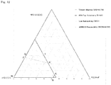
- Preferable refrigerant A is as follows: When the mass% of HFO-1132(E), HFO-1123, and R1234yf based on their sum in the refrigerant is respectively represented by x, y, and z, coordinates (x,y,z) in a ternary composition diagram in which the sum of HFO-1132(E), HFO-1123, and R1234yf is 100 mass% are within the range of a figure surrounded by line segments AA', A'B, BD, DC', C'C, CO, and OA that connect the following 7 points:
- the refrigerant according to the present disclosure has a refrigerating capacity ratio of 85% or more relative to that of R410A, and a COP of 92.5% or more relative to that of R410A.
- the refrigerant is preferably a refrigerant wherein coordinates (x,y,z) in a ternary composition diagram in which the sum of HFO-1132(E), HFO-1123, and R1234yf is 100 mass% are within a figure surrounded by line segments GI, IA, AA', A'B, BD, DC', C'C, and CG that connect the following 8 points:
- the refrigerant A according to the present disclosure has a refrigerating capacity ratio of 85% or more relative to that of R410A, and a COP of 92.5% or more relative to that of R410A; furthermore, the refrigerant A has a WCF lower flammability according to the ASHRAE Standard (the WCF composition has a burning velocity of 10 cm/s or less).
- the refrigerant is preferably a refrigerant wherein coordinates (x,y,z) in a ternary composition diagram in which the sum of HFO-1132(E), HFO-1123, and R1234yf is 100 mass% are within the range of a figure surrounded by line segments JP, PN, NK, KA', A'B, BD, DC', C'C, and CJ that connect the following 9 points:
- the refrigerant A according to the present disclosure has a refrigerating capacity ratio of 85% or more relative to that of R410A, and a COP of 92.5% or more relative to that of R410A; furthermore, the refrigerant exhibits a lower flammability (Class 2L) according to the ASHRAE Standard (the WCF composition and the WCFF composition have a burning velocity of 10 cm/s or less).
- the refrigerant is preferably a refrigerant wherein coordinates (x,y,z) in a ternary composition diagram in which the sum of HFO-1132(E), HFO-1123, and R1234yf is 100 mass% are within the range of a figure surrounded by line segments JP, PL, LM, MA', A'B, BD, DC', C'C, and CJ that connect the following 9 points:
- the refrigerant according to the present disclosure has a refrigerating capacity ratio of 85% or more relative to that of R410A, and a COP of 92.5% or more relative to that of R410A; furthermore, the refrigerant has an RCL of 40 g/m 3 or more.
- the refrigerant is preferably a refrigerant wherein coordinates (x,y,z) in a ternary composition diagram in which the sum of HFO-1132(E), HFO-1123, and R1234yf is 100 mass% are within the range of a figure surrounded by line segments PL, LM, MA', A'B, BF, FT, and TP that connect the following 7 points:
- the refrigerant according to the present disclosure has a refrigerating capacity ratio of 85% or more relative to that of R410A, and a COP of 95% or more relative to that of R410A; furthermore, the refrigerant has an RCL of 40 g/m 3 or more.
- the refrigerant A according to the present disclosure is preferably a refrigerant wherein when the mass% of HFO-1132(E), HFO-1123, and R1234yf based on their sum in the refrigerant is respectively represented by x, y, and z, coordinates (x,y,z) in a ternary composition diagram in which the sum of HFO-1132(E), HFO-1123, and R1234yf is 100 mass% are within the range of a figure surrounded by line segments PL, LQ, QR, and RP that connect the following 4 points:
- the refrigerant according to the present disclosure has a COP of 95% or more relative to that of R410A, and an RCL of 40 g/m 3 or more, furthermore, the refrigerant has a condensation temperature glide of 1°C or less.
- the refrigerant A according to the present disclosure is preferably a refrigerant wherein when the mass% of HFO-1132(E), HFO-1123, and R1234yf based on their sum in the refrigerant is respectively represented by x, y, and z, coordinates (x,y,z) in a ternary composition diagram in which the sum of HFO-1132(E), HFO-1123, and R1234yf is 100 mass% are within the range of a figure surrounded by line segments SM, MA', A'B, BF, FT, and TS that connect the following 6 points:
- the refrigerant according to the present disclosure has a refrigerating capacity ratio of 85% or more relative to that of R410A, a COP of 95% or more relative to that of R410A, and an RCL of 40 g/m 3 or more furthermore, the refrigerant has a discharge pressure of 105% or more relative to that of R410A.
- the refrigerant A according to the present disclosure is preferably a refrigerant wherein when the mass% of HFO-1132(E), HFO-1123, and R1234yf based on their sum in the refrigerant is respectively represented by x, y, and z, coordinates (x,y,z) in a ternary composition diagram in which the sum of HFO-1132(E), HFO-1123, and R1234yf is 100 mass% are within the range of a figure surrounded by line segments Od, dg, gh, and hO that connect the following 4 points:
- the refrigerant according to the present disclosure has a refrigerating capacity ratio of 92.5% or more relative to that of R410A, and a COP ratio of 92.5% or more relative to that of R410A.
- the refrigerant A according to the present disclosure is preferably a refrigerant wherein
- the refrigerant according to the present disclosure has a refrigerating capacity ratio of 92.5% or more relative to that of R410A, and a COP ratio of 92.5% or more relative to that of R410A; furthermore, the refrigerant has a lower flammability (Class 2L) according to the ASHRAE Standard.
- the refrigerant A according to the present disclosure is preferably a refrigerant wherein
- the refrigerant according to the present disclosure has a refrigerating capacity ratio of 93.5% or more relative to that of R410A, and a COP ratio of 93.5% or more relative to that of R410A.
- the refrigerant A according to the present disclosure is preferably a refrigerant wherein
- the refrigerant according to the present disclosure has a refrigerating capacity ratio of 93.5% or more relative to that of R410A, and a COP ratio of 93.5% or more relative to that of R410A; furthermore, the refrigerant has a lower flammability (Class 2L) according to the ASHRAE Standard.
- the refrigerant A according to the present disclosure is preferably a refrigerant wherein
- the refrigerant according to the present disclosure has a refrigerating capacity ratio of 95% or more relative to that of R410A, and a COP ratio of 95% or more relative to that of R410A.
- the refrigerant A according to the present disclosure is preferably a refrigerant wherein
- the refrigerant according to the present disclosure has a refrigerating capacity ratio of 95% or more relative to that of R410A, and a COP ratio of 95% or more relative to that of R410A; furthermore, the refrigerant has a lower flammability (Class 2L) according to the ASHRAE Standard.
- the refrigerant according to the present disclosure may further comprise other additional refrigerants in addition to HFO-1132(E), HFO-1123, and R1234yf, as long as the above properties and effects are not impaired.
- the refrigerant according to the present disclosure preferably comprises HFO-1132(E), HFO-1123, and R1234yf in a total amount of 99.5 mass% or more, more preferably 99.75 mass% or more, and still more preferably 99.9 mass% or more, based on the entire refrigerant.
- the refrigerant according to the present disclosure may comprise HFO-1132(E), HFO-1123, and R1234yf in a total amount of 99.5 mass% or more, 99.75 mass% or more, or 99.9 mass% or more, based on the entire refrigerant.
- Additional refrigerants are not particularly limited and can be widely selected.
- the mixed refrigerant may contain one additional refrigerant, or two or more additional refrigerants.
- refrigerant A is not limited to the Examples.
- the refrigerating capacity of R410A and compositions each comprising a mixture of HFO-1132(E), HFO-1123, and R1234yf was determined by performing theoretical refrigeration cycle calculations for the mixed refrigerants using the National Institute of Science and Technology (NIST) and Reference Fluid Thermodynamic and Transport Properties Database (Refprop 9.0) under the following conditions.
- the RCL of the mixture was calculated with the LFL of HFO-1132(E) being 4.7 vol.%, the LFL of HFO-1123 being 10 vol.%, and the LFL of R1234yf being 6.2 vol.%, in accordance with the ASHRAE Standard 34-2013.
- Tables 1 to 34 show these values together with the GWP of each mixed refrigerant.
- Table 1 Item Unit Comp. Ex. 1 Comp. Ex. 2 Comp. Ex. 3 Example 1 Example 2 Example 3 Comp. Ex. 4 O A A' B HFO-1132(E) mass% R410A 100.0 68.6 49.0 30.6 14.1 0.0 HFO-1123 mass% 0.0 0.0 14.9 30.0 44.8 58.7 R1234yf mass% 0.0 31.4 36.1 39.4 41.1 41.3 GWP - 2088 1 2 2 2 2 2 2 COP ratio % (relative to 410A) 100 99.7 100.0 98.6 97.3 96.3 95.5 Refrigerating capacity ratio % (relative to 410A) 100 98.3 85.0 85.0 85.0 85.0 85.0 Condensation glide °C 0.1 0.00 1.98 3.36 4.46 5.15 5.35 Discharge pressure % (relative to 410A) 100.0 99.3 87.1 88.9 90.6 92.1 93.2
- Example 9 Example 10
- Example 11 Example 12 J P L N N' K HFO-1132(E) mass% 47.1 55.8 63.1 68.6 65.0 61.3 HFO-1123 mass% 52.9 42.0 31.9 16.3 7.7 5.4
- R1234yf mass% 0.0 2.2 5.0 15.1 27.3 33.3
- GWP - 1 1 1 1 2 2 COP ratio % (relative to 410A) 93.8 95.0 96.1 97.9 99.1 99.5
- Refrigerating capacity ratio % (relative to 410A) 106.2 104.1 101.6 95.0 88.2 85.0 Condensation glide °C 0.31 0.57 0.81 1.41 2.11 2.51 Discharge pressure % (relative to 410A) 115.8 111.9 107.8 99.0 91.2 87.7 RCL g/m 3 46.2 42.6 40.0 38.0 38.7 39.7
- Table 4 Item Unit Example 13
- Example 14 Example 15
- Example 16 Example 17
- Example 18 Example 19
- Example 20 Example 21 G H I HFO-1132(E) mass% 72.0 72.0 72.0 HFO-1123 mass% 28.0 14.0 0.0 R1234yf mass% 0.0 14.0 28.0 GWP - 1 1 2 COP ratio % (relative to 410A) 96.6 98.2 99.9 Refrigerating capacity ratio % (relative to 410A) 103.1 95.1 86.6 Condensation glide °C 0.46 1.27 1.71 Discharge pressure % (relative to 410A) 108.4 98.7 88.6 RCL g/m 3 37.4 37.0 36.6 Table 6 Item Unit Comp. Ex. 11 Comp. Ex. 12 Example 22 Example 23 Example 24 Example 25 Example 26 Comp. Ex.
- Example 32 Comp. Ex. 15 HFO-1132(E) mass% 10.0 20.0 30.0 40.0 50.0 60.0 70.0 80.0 HFO-1123 mass% 80.0 70.0 60.0 50.0 40.0 30.0 20.0 10.0 R1234yf mass% 10.0 10.0 10.0 10.0 10.0 10.0 10.0 10.0 GWP - 1 1 1 1 1 1 1 1 COP ratio % (relative to 410A) 91.9 92.5 93.3 94.3 95.3 96.4 97.5 98.6 Refrigerating capacity ratio % (relative to 410A) 103.2 102.9 102.4 101.5 100.5 99.2 97.8 96.2 Condensation glide °C 0.87 0.94 1.03 1.12 1.18 1.18 1.09 0.88 Discharge pressure % (relative to 410A) 116.7 115.2 113.2 110.8 108.1 105.2 102.1 99.0 RCL g/m 3 70.5 61.6 54.6 49.1 44.6 40.8 37.7 35.0 Table 8 Item Unit Comp
- the point on the line segment AA' was determined by obtaining an approximate curve connecting point A, Example 1, and point A' by the least square method.
- the point on the line segment A'B was determined by obtaining an approximate curve connecting point A', Example 3, and point B by the least square method.
- the point on the line segment DC' was determined by obtaining an approximate curve connecting point D, Example 6, and point C' by the least square method.
- the point on the line segment C'C was determined by obtaining an approximate curve connecting point C', Example 4, and point C by the least square method.
- the point on the line segment FT was determined by obtaining an approximate curve connecting three points, i.e., points T, E', and F, by the least square method.
- the point on the line segment TE was determined by obtaining an approximate curve connecting three points, i.e., points E, R, and T, by the least square method.
- the composition preferably contains R1234yf.
- FIG. 1 A burning velocity test was performed using the apparatus shown in Fig. 1 in the following manner.
- reference numeral 901 refers to a sample cell
- 902 refers to a high-speed camera
- 903 refers to a xenon lamp
- 904 refers to a collimating lens
- 905 refers to a collimating lens
- 906 refers to a ring filter.
- the mixed refrigerants used had a purity of 99.5% or more, and were degassed by repeating a cycle of freezing, pumping, and thawing until no traces of air were observed on the vacuum gauge.
- the burning velocity was measured by the closed method.
- the initial temperature was ambient temperature.
- Ignition was performed by generating an electric spark between the electrodes in the center of a sample cell.
- the duration of the discharge was 1.0 to 9.9 ms, and the ignition energy was typically about 0.1 to 1.0 J.
- the spread of the flame was visualized using schlieren photographs.
- a cylindrical container (inner diameter: 155 mm, length: 198 mm) equipped with two light transmission acrylic windows was used as the sample cell, and a xenon lamp was used as the light source.
- Schlieren images of the flame were recorded by a high-speed digital video camera at a frame rate of 600 fps and stored on a PC.
- Each WCFF concentration was obtained by using the WCF concentration as the initial concentration and performing a leak simulation using NIST Standard Reference Database REFLEAK Version 4.0.
- Tables 35 and 36 show the results.
- Table 35 Item Unit G H I WCF HFO-1132(E) mass% 72.0 72.0 72.0 HFO-1123 mass% 28.0 9.6 0.0 R1234yf mass% 0.0 18.4 28.0 Burning velocity (WCF) cm/s 10 10 10
- Table 36 Item Unit J P L N N' K WCF HFO-1132 (E) mass% 47.1 55.8 63.1 68.6 65.0 61.3 HFO-1123 mass% 52.9 42.0 31.9 16.3 7.7 5.4 R1234yf mass% 0.0 2.2 5.0 15.1 27.3 33.3 Leak condition that results in WCFF Storage/ Shipping -40°C, 92% release, liquid phase side Storage/ Shipping -40°C, 90% release, liquid phase side Storage/ Shipping -40°C, 90% release, gas phase side Storage/ Shipping -40°C, 66% release, gas phase side Storage/ Shipping -40°C, 12% release, gas phase side Storage/ Shipping, -40°C, 0% release, gas phase side WCFF HFO
- Tables 36 clearly indicate that in a ternary composition diagram of a mixed refrigerant of HFO-1132(E), HFO-1123, and R1234yf in which their sum is 100 mass%, and a line segment connecting a point (0.0, 100.0, 0.0) and a point (0.0, 0.0, 100.0) is the base, when coordinates (x,y,z) are on or below the line segments JP, PN, and NK connecting the following 6 points:
- the point on the line segment PN was determined by obtaining an approximate curve connecting three points, i.e., points P, L, and N, by the least square method.
- the point on the line segment NK was determined by obtaining an approximate curve connecting three points, i.e., points N, N', and K, by the least square method.
- the refrigerant B according to the present disclosure is
- the refrigerant B according to the present disclosure has various properties that are desirable as an R410A-alternative refrigerant, i.e., (1) a coefficient of performance equivalent to that of R410A, (2) a refrigerating capacity equivalent to that of R410A, (3) a sufficiently low GWP, and (4) a lower flammability (Class 2L) according to the ASHRAE standard.
- the refrigerant B according to the present disclosure is a mixed refrigerant comprising 72.0 mass% or less of HFO-1132(E), it has WCF lower flammability.
- the refrigerant B according to the present disclosure is a composition comprising 47.1% or less of HFO-1132(E), it has WCF lower flammability and WCFF lower flammability, and is determined to be "Class 2L,” which is a lower flammable refrigerant according to the ASHRAE standard, and which is further easier to handle.
- the refrigerant B according to the present disclosure comprises 62.0 mass% or more of HFO-1132(E), it becomes superior with a coefficient of performance of 95% or more relative to that of R410A, the polymerization reaction of HFO-1132(E) and/or HFO-1123 is further suppressed, and the stability is further improved.
- the refrigerant B according to the present disclosure comprises 45.1 mass% or more of HFO-1132(E), it becomes superior with a coefficient of performance of 93% or more relative to that of R410A, the polymerization reaction of HFO-1132(E) and/or HFO-1123 is further suppressed, and the stability is further improved.
- the refrigerant B according to the present disclosure may further comprise other additional refrigerants in addition to HFO-1132(E) and HFO-1123, as long as the above properties and effects are not impaired.
- the refrigerant according to the present disclosure preferably comprises HFO-1132(E) and HFO-1123 in a total amount of 99.75 mass% or more, and more preferably 99.9 mass% or more, based on the entire refrigerant.
- additional refrigerants are not limited, and can be selected from a wide range of refrigerants.
- the mixed refrigerant may comprise a single additional refrigerant, or two or more additional refrigerants.
- refrigerant B is not limited to the Examples.
- the refrigerating capacity of compositions each comprising R410A and a mixture of HFO-1132(E) and HFO-1123 was determined by performing theoretical refrigeration cycle calculations for the mixed refrigerants using the National Institute of Science and Technology (NIST) and Reference Fluid Thermodynamic and Transport Properties Database (Refprop 9.0) under the following conditions. Evaporating temperature: 5°C Condensation temperature: 45°C Superheating temperature: 5 K Subcooling temperature: 5 K Compressor efficiency: 70%
- composition of each mixture was defined as WCF.
- a leak simulation was performed using NIST Standard Reference Data Base Refleak Version 4.0 under the conditions of Equipment, Storage, Shipping, Leak, and Recharge according to the ASHRAE Standard 34-2013.
- the most flammable fraction was defined as WCFF.
- Tables 1 and 2 show GWP, COP, and refrigerating capacity, which were calculated based on these results.
- the COP and refrigerating capacity are ratios relative to R410A.
- COP coefficient of performance
- the burning velocity was measured according to the ANSI/ASHRAE Standard 34-2013. Both WCF and WCFF having a burning velocity of 10 cm/s or less were determined to be "Class 2L (lower flammability)."
- a burning velocity test was performed using the apparatus shown in Fig. 1 in the following manner.
- the mixed refrigerants used had a purity of 99.5% or more, and were degassed by repeating a cycle of freezing, pumping, and thawing until no traces of air were observed on the vacuum gauge.
- the burning velocity was measured by the closed method.
- the initial temperature was ambient temperature.
- Ignition was performed by generating an electric spark between the electrodes in the center of a sample cell.
- the duration of the discharge was 1.0 to 9.9 ms, and the ignition energy was typically about 0.1 to 1.0 J.
- the spread of the flame was visualized using schlieren photographs.
- a cylindrical container (inner diameter: 155 mm, length: 198 mm) equipped with two light transmission acrylic windows was used as the sample cell, and a xenon lamp was used as the light source.
- Schlieren images of the flame were recorded by a high-speed digital video camera at a frame rate of 600 fps and stored on a PC.
- the refrigerant C according to the present disclosure is a composition comprising trans-1,2-difluoroethylene (HFO-1132(E)), trifluoroethylene (HFO-1123), 2,3,3,3-tetrafluoro-1-propene (R1234yf), and difluoromethane (R32), and satisfies the following requirements.
- the refrigerant C according to the present disclosure has various properties that are desirable as an alternative refrigerant for R410A; i.e. it has a coefficient of performance and a refrigerating capacity that are equivalent to those of R410A, and a sufficiently low GWP
- Preferable refrigerant C is as follows: When the mass% of HFO-1132(E), HFO-1123, R1234yf, and R32 based on their sum is respectively represented by x, y, z, and a,
- the refrigerant C according to the present disclosure is preferably a refrigerant wherein
- the refrigerant C when the refrigerant C according to the present disclosure further contains R32 in addition to HFO-1132 (E), HFO-1123, and R1234yf, the refrigerant may be a refrigerant wherein when the mass% of HFO-1132(E), HFO-1123, R1234yf, and R32 based on their sum is respectively represented by x, y, z, and a,
- the refrigerant C according to the present disclosure may further comprise other additional refrigerants in addition to HFO-1132(E), HFO-1123, R1234yf, and R32 as long as the above properties and effects are not impaired.
- the refrigerant according to the present disclosure preferably comprises HFO-1132(E), HFO-1123, R1234yf, and R32 in a total amount of 99.5 mass% or more, more preferably 99.75 mass% or more, and still more preferably 99.9 mass% or more, based on the entire refrigerant.
- the refrigerant C according to the present disclosure may comprise HFO-1132(E), HFO-1123, R1234yf, and R32 in a total amount of 99.5 mass% or more, 99.75 mass% or more, or 99.9 mass% or more, based on the entire refrigerant.
- Additional refrigerants are not particularly limited and can be widely selected.
- the mixed refrigerant may contain one additional refrigerant, or two or more additional refrigerants.
- refrigerant C is not limited to the Examples.
- the refrigerating capacity of compositions each comprising R410A and a mixture of HFO-1132(E) and HFO-1123 was determined by performing theoretical refrigeration cycle calculations for the mixed refrigerants using the National Institute of Science and Technology (NIST) and Reference Fluid Thermodynamic and Transport Properties Database (Refprop 9.0) under the following conditions.
- Tables 39 to 96 show the resulting values together with the GWP of each mixed refrigerant.
- the COP and refrigerating capacity are ratios relative to R410A.
- COP coefficient of performance
- the COP ratio of 92.5% or more forms a curved line CD.
- Fig. 3 an approximate line formed by connecting three points: point C (32.9, 67.1, 0.0) and points (26.6, 68.4, 5) (19.5, 70.5, 10) where the COP ratio is 92.5% when the concentration of R1234yf is 5 mass% and 10 mass was obtained, and a straight line that connects point C and point D' (0, 75.4, 24.6), which is the intersection of the approximate
- point D'(0, 83.4, 9.5) was similarly obtained from an approximate curve formed by connecting point C (18.4, 74.5, 0) and points (13.9, 76.5, 2.5) (8.7, 79.2, 5) where the COP ratio is 92.5%, and a straight line that connects point C and point D' was defined as the straight line D'C.
- composition of each mixture was defined as WCF.
- a leak simulation was performed using NIST Standard Reference Database REFLEAK Version 4.0 under the conditions of Equipment, Storage, Shipping, Leak, and Recharge according to the ASHRAE Standard 34-2013.
- the most flammable fraction was defined as WCFF.
- the burning velocity was measured according to the ANSI/ASHRAE Standard 34-2013. Both WCF and WCFF having a burning velocity of 10 cm/s or less were determined to be classified as "Class 2L (lower flammability)."
- a burning velocity test was performed using the apparatus shown in Fig. 1 in the following manner.
- the mixed refrigerants used had a purity of 99.5% or more, and were degassed by repeating a cycle of freezing, pumping, and thawing until no traces of air were observed on the vacuum gauge.
- the burning velocity was measured by the closed method.
- the initial temperature was ambient temperature.
- Ignition was performed by generating an electric spark between the electrodes in the center of a sample cell.
- the duration of the discharge was 1.0 to 9.9 ms, and the ignition energy was typically about 0.1 to 1.0 J.
- the spread of the flame was visualized using schlieren photographs.
- a cylindrical container (inner diameter: 155 mm, length: 198 mm) equipped with two light transmission acrylic windows was used as the sample cell, and a xenon lamp was used as the light source.
- Schlieren images of the flame were recorded by a high-speed digital video camera at a frame rate of 600 fps and stored on a PC.
- Figs. 3 to 13 show compositions whose R32 content a (mass%) is 0 mass%, 7.1 mass%, 11.1 mass%, 14.5 mass%, 18.2 mass%, 21.9 mass%, 26.7 mass%, 29.3 mass%, 36.7 mass%, 44.1 mass%, and 47.8 mass%, respectively.
- Points A, B, C, and D' were obtained in the following manner according to approximate calculation.
- Point A is a point where the content of HFO-1123 is 0 mass%, and a refrigerating capacity ratio of 85% relative to that of R410A is achieved. Three points corresponding to point A were obtained in each of the following five ranges by calculation, and their approximate expressions were obtained (Table 109).
- Point B is a point where the content of HFO-1132(E) is 0 mass%, and a refrigerating capacity ratio of 85% relative to that of R410A is achieved.
- Point D' is a point where the content of HFO-1132(E) is 0 mass%, and a COP ratio of 95.5% relative to that of R410A is achieved.
- Point C is a point where the content of R1234yf is 0 mass%, and a COP ratio of 95.5% relative to that of R410A is achieved.
- the refrigerant D is a mixed refrigerant comprising trans-1,2-difluoroethylene (HFO-1132(E)), difluoromethane (R32), and 2,3,3,3-tetrafluoro-1-propene (R1234yf).
- the refrigerant D according to the present disclosure has various properties that are desirable as an R410A-alternative refrigerant; i.e., a refrigerating capacity equivalent to that of R410A, a sufficiently low GWP, and a lower flammability (Class 2L) according to the ASHRAE standard.
- the refrigerant D according to the present disclosure is preferably a refrigerant wherein
- the refrigerant D according to the present disclosure is preferably a refrigerant wherein
- the refrigerant D according to the present disclosure is preferably a refrigerant wherein
- the refrigerant D according to the present disclosure is preferably a refrigerant wherein
- the refrigerant D according to the present disclosure is preferably a refrigerant wherein
- the refrigerant D according to the present disclosure is preferably a refrigerant wherein
- the refrigerant D according to the present disclosure is preferably a refrigerant wherein
- the refrigerant D according to the present disclosure is preferably a refrigerant wherein
- the refrigerant D according to the present disclosure is preferably a refrigerant wherein
- the refrigerant D according to the present disclosure may further comprise other additional refrigerants in addition to HFO-1132(E), R32, and R1234yf, as long as the above properties and effects are not impaired.
- the refrigerant according to the present disclosure preferably comprises HFO-1132(E), R32, and R1234yf in a total amount of 99.5 mass% or more, more preferably 99.75 mass% or more, and still more preferably 99.9 mass% or more based on the entire refrigerant.
- additional refrigerants are not limited, and can be selected from a wide range of refrigerants.
- the mixed refrigerant may comprise a single additional refrigerant, or two or more additional refrigerants.
- refrigerant D is not limited to the Examples.
- composition of each mixed refrigerant of HFO-1132(E), R32, and R1234yf was defined as WCF.
- a leak simulation was performed using the NIST Standard Reference Database REFLEAK Version 4.0 under the conditions of Equipment, Storage, Shipping, Leak, and Recharge according to the ASHRAE Standard 34-2013.
- the most flammable fraction was defined as WCFF.
- a burning velocity test was performed using the apparatus shown in Fig. 1 in the following manner.
- the mixed refrigerants used had a purity of 99.5% or more, and were degassed by repeating a cycle of freezing, pumping, and thawing until no traces of air were observed on the vacuum gauge.
- the burning velocity was measured by the closed method.
- the initial temperature was ambient temperature.
- Ignition was performed by generating an electric spark between the electrodes in the center of a sample cell.
- the duration of the discharge was 1.0 to 9.9 ms, and the ignition energy was typically about 0.1 to 1.0 J.
- the spread of the flame was visualized using schlieren photographs.
- a cylindrical container (inner diameter: 155 mm, length: 198 mm) equipped with two light transmission acrylic windows was used as the sample cell, and a xenon lamp was used as the light source.
- Schlieren images of the flame were recorded by a high-speed digital video camera at a frame rate of 600 fps and stored on a PC. Tables 113 to 115 show the results.
- Example 11 Example 12
- Example 13 Example 14
- Example 16 I J K L WCF HFO-1132 (E) Mass% 72 57.2 48.5 41.2 35.6 32 28.9 R32 Mass% 0 10 18.3 27.6 36.8 44.2 51.7 R1234yf Mass% 28 32.8 33.2 31.2 27.6 23.8 19.4 Burning Velocity (WCF) cm/s 10 10 10 10 10 10
- Table 114 Item Unit Comparative Example 14
- Example 19 Example 20
- Example 21 Example 22 M W N WCF HFO-1132 (E) Mass% 52.6 39.2 32.4 29.3 27.7 24.6
- Tables 116 to 144 show these values together with the GWP of each mixed refrigerant.
- Table 116 Item Unit Comparative Example 1 Comparative Example 2 Comparative Example 3 Comparative Example 4 Comparative Example 5 Comparative Example 6 Comparative Example 7 A B A' B' A" B" HFO-1132(E) Mass% R410A 81.6 0.0 63.1 0.0 48.2 0.0 R32 Mass% 18.4 18.1 36.9 36.7 51.8 51.5 R1234yf Mass% 0.0 81.9 0.0 63.3 0.0 48.5 GWP - 2088 125 125 250 250 350 350 COP Ratio %(relative to R410A) 100 98.7 103.6 98.7 102.3 99.2 102.2 Refrigerating Capacity Ratio %(relative to R410A) 100 105.3 62.5 109.9 77.5 112.1 87.3 Table 117 Item Unit Comparative Example 8 Comparative Example 9 Comparative Example 10 Example 1 Example 2 Example 3 Example 4 C C' R T HFO-1132(E) Mass%
- the refrigerant E is a mixed refrigerant comprising trans-1,2-difluoroethylene (HFO-1132(E)), trifluoroethylene (HFO-1123), and difluoromethane (R32).
- the refrigerant E according to the present disclosure has various properties that are desirable as an R410A-alternative refrigerant, i.e., a coefficient of performance equivalent to that of R410A and a sufficiently low GWP
- the refrigerant E according to the present disclosure is preferably a refrigerant wherein
- the refrigerant E according to the present disclosure is preferably a refrigerant wherein
- the refrigerant E according to the present disclosure is preferably a refrigerant wherein
- the refrigerant E according to the present disclosure is preferably a refrigerant wherein
- the refrigerant E according to the present disclosure is preferably a refrigerant wherein
- the refrigerant E according to the present disclosure is preferably a refrigerant wherein
- the refrigerant E according to the present disclosure is preferably a refrigerant wherein
- the refrigerant E according to the present disclosure is preferably a refrigerant wherein
- the refrigerant E according to the present disclosure is preferably a refrigerant wherein
- the refrigerant E according to the present disclosure is preferably a refrigerant wherein
- the refrigerant E according to the present disclosure may further comprise other additional refrigerants in addition to HFO-1132(E), HFO-1123, and R32, as long as the above properties and effects are not impaired.
- the refrigerant according to the present disclosure preferably comprises HFO-1132(E), HFO-1123, and R32 in a total amount of 99.5 mass% or more, more preferably 99.75 mass% or more, and even more preferably 99.9 mass% or more, based on the entire refrigerant.
- additional refrigerants are not limited, and can be selected from a wide range of refrigerants.
- the mixed refrigerant may comprise a single additional refrigerant, or two or more additional refrigerants.
- refrigerant E is not limited to the Examples.
- composition of each mixture was defined as WCF.
- a leak simulation was performed using National Institute of Science and Technology (NIST) Standard Reference Data Base Refleak Version 4.0 under the conditions for equipment, storage, shipping, leak, and recharge according to the ASHRAE Standard 34-2013.
- the most flammable fraction was defined as WCFF.
- the burning velocity was measured according to the ANSI/ASHRAE Standard 34-2013.
- the burning velocities of the WCF composition and the WCFF composition are 10 cm/s or less, the flammability of such a refrigerant is classified as Class 2L (lower flammability) in the ASHRAE flammability classification.
- a burning velocity test was performed using the apparatus shown in Fig. 1 in the following manner.
- the mixed refrigerants used had a purity of 99.5% or more, and were degassed by repeating a cycle of freezing, pumping, and thawing until no traces of air were observed on the vacuum gauge.
- the burning velocity was measured by the closed method.
- the initial temperature was ambient temperature.
- Ignition was performed by generating an electric spark between the electrodes in the center of a sample cell.
- the duration of the discharge was 1.0 to 9.9 ms, and the ignition energy was typically about 0.1 to 1.0 J.
- the spread of the flame was visualized using schlieren photographs.
- a cylindrical container (inner diameter: 155 mm, length: 198 mm) equipped with two light transmission acrylic windows was used as the sample cell, and a xenon lamp was used as the light source.
- Schlieren images of the flame were recorded by a high-speed digital video camera at a frame rate of 600 fps and stored on a PC.
- Tables 145 and 146 show the results.
- Table 145 Item Unit I J K L WCF HFO-1132(E) mass% 72.0 57.7 48.4 35.5 HFO-1123 mass% 28.0 32.8 33.2 27.5 R32 mass% 0.0 9.5 18.4 37.0 Burning velocity (WCF) cm/s 10 10 10 10
- Table 146 Item Unit M N T P U Q WCF HFO-1132(E) mass% 47.1 38.5 34.8 31.8 28.7 28.6 HFO-1123 mass% 52.9 52.1 51.0 49.8 41.2 34.4 R32 mass% 0.0 9.5 14.2 18.4 30.1 37.0 Leak condition that results in WCFF Storage, Shipping, -40°C, 92%, release, on the liquid phase side Storage, Shipping, -40°C, 92%, release, on the liquid phase side Storage, Shipping, -40°C, 92%, release, on the liquid phase side Storage, Shipping, -40°C, 92%, release, on the liquid phase side Storage, Shipping, -40°C, 9
- Table 1 indicate that in a ternary composition diagram of a mixed refrigerant of HFO-1132(E), HFO-1123, and R32 in which their sum is 100 mass%, a line segment connecting a point (0.0, 100.0, 0.0) and a point (0.0, 0.0, 100.0) is the base, the point (0.0, 100.0, 0.0) is on the left side, and the point (0.0, 0.0, 100.0) is on the right side, when coordinates (x,y,z) are on or below line segments IK and KL that connect the following 3 points:
- Table 146 indicate that in a ternary composition diagram of a mixed refrigerant of HFO-1132(E), HFO-1123, and R32 in which their sum is 100 mass%, a line segment connecting a point (0.0, 100.0, 0.0) and a point (0.0, 0.0, 100.0) is the base, the point (0.0, 100.0, 0.0) is on the left side, and the point (0.0, 0.0, 100.0) is on the right side, when coordinates (x,y,z) are on or below line segments MP and PQ that connect the following 3 points:
- the line segment MP is represented by coordinates (0.0083z 2 -0.984z+47.1, -0.0083z 2 -0.016z+52.9, z)
- the line segment PQ is represented by coordinates (0.0135z 2 -0.9181z+44.133, -0.0135z 2 -0.0819z+55.867, z).
- an approximate curve was obtained from three points, i.e., points M, N, and P, by using the least-square method to determine coordinates.
- an approximate curve was obtained from three points, i.e., points P, U, and Q, by using the least-square method to determine coordinates.
- the refrigerating capacity of compositions each comprising R410A and a mixture of HFO-1132(E) and HFO-1123 was determined by performing theoretical refrigeration cycle calculations for the mixed refrigerants using the National Institute of Science and Technology (NIST) and Reference Fluid Thermodynamic and Transport Properties Database (Refprop 9.0) under the following conditions.
- the COP ratio and the refrigerating capacity (which may be referred to as “cooling capacity” or “capacity”) ratio relative to those of R410 of the mixed refrigerants were determined.
- the conditions for calculation were as described below.
- Tables 147 to 166 show these values together with the GWP of each mixed refrigerant.
- Table 147 Item Unit Comparative Example 1 Comparative Example 2 Comparative Example 3 Comparative Example 4 Comparative Example 5 Comparative Example 6 Comparative Example 7 A B A' B' A" B" HFO-1132(E) mass% R410A 90.5 0.0 81.6 0.0 63.0 0.0 HFO-1123 mass% 0.0 90.5 0.0 81.6 0.0 63.0 R32 mass% 9.5 9.5 18.4 18.4 37.0 37.0 GWP - 2088 65 65 125 125 250 250 COP ratio % (relative to R410A) 100 99.1 92.0 98.7 93.4 98.7 96.1 Refrigerating capacity ratio % (relative to R410A) 100 102.2 111.6 105.3 113.7 110.0 115.4 Table 148 Item Unit Comparative Example 8 Comparative Example 9 Comparative Example 10 Example 1 Example 2 Comparative Example 11 O C U D HFO-1132(E) mass% 100.0 50.0 41.1 28.
- the line segment CU is represented by coordinates (-0.0538z 2 +0.7888z+53.701, 0.0538z 2 -1.7888z+46.299, z)
- the line segment UD is represented by coordinates (-3.4962z 2 +210.71z-3146.1, 3.4962z 2 -211.71z+3246.1, z).
- the points on the line segment CU are determined from three points, i.e., point C, Comparative Example 10, and point U, by using the least-square method.
- the points on the line segment UD are determined from three points, i.e., point U, Example 2, and point D, by using the least-square method.
- the line segment ET is represented by coordinates (-0.0547z 2 -0.5327z+53.4, 0.0547z 2 -0.4673z+46.6, z)
- the line segment TF is represented by coordinates (-0.0982z 2 +0.9622z+40.931, 0.0982z 2 -1.9622z+59.069, z).
- the points on the line segment ET are determined from three points, i.e., point E, Example 2, and point T, by using the least-square method.
- the points on the line segment TF are determined from three points, i.e., points T, S, and F, by using the least-square method.
- the line segment GR is represented by coordinates (-0.0491z 2 -* 1.1544z+38.5, 0.0491z 2 +0.18544z+61.5, z), and the line segment RH is represented by coordinates (-0.3123z 2 +4.234z+11.06, 0.3123z 2 -5.234z+88.94, z).
- the points on the line segment GR are determined from three points, i.e., point G, Example 5, and point R, by using the least-square method.
- the points on the line segment RH are determined from three points, i.e., point R, Example 7, and point H, by using the least-square method.
- Fig. 16 is the schematic configuration diagram of a refrigerant circuit
- Fig. 17 is a schematic control block configuration diagram.
- the air conditioner 1 is an apparatus that air-conditions a space to be air-conditioned by performing a vapor compression refrigeration cycle.
- the air conditioner 1 mainly includes an outdoor unit 20, an indoor unit 30, a liquid-side connection pipe 6 and a gas-side connection pipe 5 connecting the outdoor unit 20 and the indoor unit 30, a remote control unit (not shown) serving as an input device and an output device, and a controller 7 that controls the operation of the air conditioner 1.
- the refrigeration cycle in which refrigerant sealed in a refrigerant circuit 10 is compressed, cooled or condensed, decompressed, heated or evaporated, and then compressed again is performed.
- the refrigerant circuit 10 is filled with refrigerant for performing a vapor compression refrigeration cycle.
- the refrigerant is a refrigerant mixture containing 1,2-difluoroethylene and may use any one of the above-described refrigerants A to E.
- the refrigerant circuit 10 is filled with refrigerating machine oil together with the refrigerant.
- a rated cooling capacity of the air conditioner 1 including only the single indoor unit 30 is not limited and may be, for example, higher than or equal to 2.0 kW and lower than or equal to 17.0 kW, and, specifically, in the air conditioner 1 of the present embodiment with a size such that no refrigerant container is provided, the rated cooling capacity is preferably higher than or equal to 2.0 kW and lower than or equal to 6.0 kW.
- the outdoor unit 20 has a structure in which a fan chamber and a machine chamber are formed (so-called, trunk structure) when the internal space of the casing 50 having substantially a rectangular parallelepiped shape into right and left spaces by a partition plate (not shown) extending vertically.
- the outdoor unit 20 is connected to the indoor unit 30 via the liquid-side connection pipe 6 and the gas-side connection pipe 5, and makes up part of the refrigerant circuit 10.
- the outdoor unit 20 mainly includes a compressor 21, a four-way valve 22, an outdoor heat exchanger 23, an outdoor expansion valve 24, an outdoor fan 25, a liquid-side stop valve 29, and a gas-side stop valve 28.
- the compressor 21 is a device that compresses low-pressure refrigerant into high pressure in the refrigeration cycle.
- the compressor 21 is a hermetically sealed compressor in which a positive-displacement, such as a rotary type and a scroll type, compression element (not shown) is driven for rotation by a compressor motor.
- the compressor motor is used to change the displacement.
- the operation frequency of the compressor motor is controllable with an inverter.
- the compressor 21 is provided with an attached accumulator (not shown) at its suction side.
- the outdoor unit 20 of the present embodiment does not have a refrigerant container larger than the attached accumulator (a low-pressure receiver disposed at the suction side of the compressor 21, a high-pressure receiver disposed at a liquid side of the outdoor heat exchanger 23, or the like).
- the four-way valve 22 is able to switch between a cooling operation connection state and a heating operation connection state by switching the status of connection.
- a cooling operation connection state a discharge side of the compressor 21 and the outdoor heat exchanger 23 are connected, and the suction side of the compressor 21 and the gas-side stop valve 28 are connected.
- the heating operation connection state the discharge side of the compressor 21 and the gas-side stop valve 28 are connected, and the suction side of the compressor 21 and the outdoor heat exchanger 23 are connected.
- the outdoor heat exchanger 23 is a heat exchanger that functions as a condenser for high-pressure refrigerant in the refrigeration cycle during cooling operation and that functions as an evaporator for low-pressure refrigerant in the refrigeration cycle during heating operation.
- the internal volume (the volume of fluid that can be filled inside) of the outdoor heat exchanger 23 is preferably greater than or equal to 0.4 L and less than or equal to 2.5 L.
- the outdoor fan 25 takes outdoor air into the outdoor unit 20, causes the air to exchange heat with refrigerant in the outdoor heat exchanger 23, and then generates air flow for emitting the air to the outside.
- the outdoor fan 25 is driven for rotation by an outdoor fan motor. In the present embodiment, only one outdoor fan 25 is provided.
- the outdoor expansion valve 24 is able to control the valve opening degree, and is provided between a liquid-side end portion of the outdoor heat exchanger 23 and the liquid-side stop valve 29.
- the liquid-side stop valve 29 is a manual valve disposed at a connection point at which the outdoor unit 20 is connected to the liquid-side connection pipe 6.
- the gas-side stop valve 28 is a manual valve disposed at a connection point at which the outdoor unit 20 is connected to the gas-side connection pipe 5.
- the outdoor unit 20 includes an outdoor unit control unit 27 that controls the operations of parts that make up the outdoor unit 20.
- the outdoor unit control unit 27 includes a microcomputer including a CPU, a memory, and the like.
- the outdoor unit control unit 27 is connected to an indoor unit control unit 34 of indoor unit 30 via a communication line, and sends or receives control signals, or the like, to or from the indoor unit control unit 34.
- the outdoor unit control unit 27 is electrically connected to various sensors (not shown), and receives signals from the sensors.
- the outdoor unit 20 includes the casing 50 having an air outlet 52.
- the casing 50 has a substantially rectangular parallelepiped shape.
- the casing 50 is able to take in outdoor air from a rear side and one side (the left side in Fig. 18 ) and is able to discharge air having passed through the outdoor heat exchanger 23 forward via the air outlet 52 formed in a front 51.
- a lower end portion of the casing 50 is covered with a bottom plate 53.
- the outdoor heat exchanger 23 is provided upright on the bottom plate 53 along the rear side and the one side.
- a top face of the bottom plate 53 can function as a drain pan.
- a drain pan heater 54 that is a sheathed heater made up of heating wires is provided along a top surface of the bottom plate 53.
- the drain pan heater 54 has a portion running along a vertically lower part of the outdoor heat exchanger 23 and a portion running along a side closer to the front than the outdoor heat exchanger 23 on the bottom plate 53.
- the drain pan heater 54 is connected to the outdoor unit control unit 27 that also serves as a power supply unit and receives electric power supply.
- the drain pan heater 54 preferably has a rated electric power consumption of lower than or equal to 300 W and, in the present embodiment, higher than or equal to 75 W and lower than or equal to 100 W.
- the indoor unit 30 is placed on a wall surface, a ceiling, or the like, in a room that is a space to be air-conditioned.
- the indoor unit 30 is connected to the outdoor unit 20 via the liquid-side connection pipe 6 and the gas-side connection pipe 5, and makes up part of the refrigerant circuit 10.
- the indoor unit 30 includes the indoor heat exchanger 31 and the indoor fan 32.
- the liquid side of the indoor heat exchanger 31 is connected to the liquid-side connection pipe 6, and the gas side of the indoor heat exchanger 31 is connected to the gas-side connection pipe 5.
- the indoor heat exchanger 31 is a heat exchanger that functions as an evaporator for low-pressure refrigerant in the refrigeration cycle during cooling operation and that functions as a condenser for high-pressure refrigerant in the refrigeration cycle during heating operation.
- the indoor fan 32 takes indoor air into the indoor unit 30, causes the air to exchange heat with refrigerant in the indoor heat exchanger 31, and then generates air flow for emitting the air to the outside.
- the indoor fan 32 is driven for rotation by an indoor fan motor.
- the indoor unit 30 includes an indoor unit control unit 34 that controls the operations of the parts that make up the indoor unit 30.
- the indoor unit control unit 34 includes a microcomputer including a CPU, a memory, and the like.
- the indoor unit control unit 34 is connected to the outdoor unit control unit 27 via a communication line, and sends or receives control signals, or the like, to or from the outdoor unit control unit 27.
- the indoor unit control unit 34 is electrically connected to various sensors (not shown) provided inside the indoor unit 30, and receives signals from the sensors.
- the outdoor unit control unit 27 and the indoor unit control unit 34 are connected via the communication line to make up the controller 7 that controls the operation of the air conditioner 1.
- the controller 7 mainly includes a CPU (central processing unit) and a memory such as a ROM and a RAM Various processes and controls made by the controller 7 are implemented by various parts included in the outdoor unit control unit 27 and/or the indoor unit control unit 34 functioning together.
- a CPU central processing unit
- a memory such as a ROM and a RAM
- the operation modes include a cooling operation mode and a heating operation mode.
- the controller 7 determines whether the operation mode is the cooling operation mode or the heating operation mode and performs the selected operation mode based on an instruction received from the remote control unit, or the like.
- the status of connection of the four-way valve 22 is set to the cooling operation connection state where the discharge side of the compressor 21 and the outdoor heat exchanger 23 are connected and the suction side of the compressor 21 and the gas-side stop valve 28 are connected, and refrigerant filled in the refrigerant circuit 10 is mainly circulated in order of the compressor 21, the outdoor heat exchanger 23, the outdoor expansion valve 24, and the indoor heat exchanger 31.
- refrigerant is taken into the compressor 21, compressed, and then discharged in the refrigerant circuit 10.
- displacement control commensurate with a cooling load that is required from the indoor unit 30 is performed.
- the displacement control is not limited.
- a target value of suction pressure may be set according to a cooling load that is required of the indoor unit 30, and the operating frequency of the compressor 21 may be controlled such that the suction pressure becomes the target value.
- Gas refrigerant discharged from the compressor 21 passes through the four-way valve 22 and flows into the gas-side end of the outdoor heat exchanger 23.
- Gas refrigerant having flowed into the gas-side end of the outdoor heat exchanger 23 exchanges heat in the outdoor heat exchanger 23 with outdoor-side air that is supplied by the outdoor fan 25 to condense into liquid refrigerant and flows out from the liquid-side end of the outdoor heat exchanger 23.
- Refrigerant having flowed out from the liquid-side end of the outdoor heat exchanger 23 is decompressed when passing through the outdoor expansion valve 24.
- the outdoor expansion valve 24 is controlled such that the degree of subcooling of refrigerant that passes through a liquid-side outlet of the outdoor heat exchanger 23 satisfies a predetermined condition.
- a method of controlling the valve opening degree of the outdoor expansion valve 24 is not limited.
- the valve opening degree of the outdoor expansion valve 24 may be controlled such that a discharge temperature of refrigerant that is discharged from the compressor 21 becomes a predetermined temperature or may be controlled such that the degree of superheating of refrigerant that is discharged from the compressor 21 satisfies a predetermined condition.
- Refrigerant decompressed in the outdoor expansion valve 24 passes through the liquid-side stop valve 29 and the liquid-side connection pipe 6 and flows into the indoor unit 30.
- Refrigerant having flowed into the indoor unit 30 flows into the indoor heat exchanger 31, exchanges heat in the indoor heat exchanger 31 with indoor air that is supplied by the indoor fan 32 to evaporate into gas refrigerant, and flows out from the gas-side end of the indoor heat exchanger 31.
- Gas refrigerant having flowed out from the gas-side end of the indoor heat exchanger 31 flows to the gas-side connection pipe 5.
- Refrigerant having flowed through the gas-side connection pipe 5 passes through the gas-side stop valve 28 and the four-way valve 22, and is taken into the compressor 21 again.
- the status of connection of the four-way valve 22 is set to the heating operation connection state where the discharge side of the compressor 21 and the gas-side stop valve 28 are connected and the suction side of the compressor 21 and the outdoor heat exchanger 23 are connected, and refrigerant filled in the refrigerant circuit 10 is mainly circulated in order of the compressor 21, the indoor heat exchanger 31, the outdoor expansion valve 24, and the outdoor heat exchanger 23.
- refrigerant is taken into the compressor 21, compressed, and then discharged in the refrigerant circuit 10.
- displacement control commensurate with a heating load that is required from the indoor unit 30 is performed.
- the displacement control is not limited.
- a target value of discharge pressure may be set according to a heating load that is required of the indoor unit 30, and the operating frequency of the compressor 21 may be controlled such that the discharge pressure becomes the target value.
- Gas refrigerant discharged from the compressor 21 flows through the four-way valve 22 and the gas-side connection pipe 5 and then flows into the indoor unit 30.
- Refrigerant having flowed into the indoor unit 30 flows into the gas-side end of the indoor heat exchanger 31, exchanges heat in the indoor heat exchanger 31 with indoor air that is supplied by the indoor fan 32 to condense into refrigerant in a gas-liquid two-phase state or liquid refrigerant, and flows out from the liquid-side end of the indoor heat exchanger 31.
- Refrigerant having flowed out from the liquid-side end of the indoor heat exchanger 31 flows into the liquid-side connection pipe 6.
- Refrigerant having flowed through the liquid-side connection pipe 6 is decompressed to a low pressure in the refrigeration cycle in the liquid-side stop valve 29 and the outdoor expansion valve 24.
- the outdoor expansion valve 24 is controlled such that the degree of subcooling of refrigerant that passes through a liquid-side outlet of the indoor heat exchanger 31 satisfies a predetermined condition.
- a method of controlling the valve opening degree of the outdoor expansion valve 24 is not limited.
- the valve opening degree of the outdoor expansion valve 24 may be controlled such that a discharge temperature of refrigerant that is discharged from the compressor 21 becomes a predetermined temperature or may be controlled such that the degree of superheating of refrigerant that is discharged from the compressor 21 satisfies a predetermined condition.
- Refrigerant decompressed in the outdoor expansion valve 24 flows into the liquid-side end of the outdoor heat exchanger 23.
- Refrigerant having flowed in from the liquid-side end of the outdoor heat exchanger 23 exchanges heat in the outdoor heat exchanger 23 with outdoor air that is supplied by the outdoor fan 25 to evaporate into gas refrigerant, and flows out from the gas-side end of the outdoor heat exchanger 23.
- Refrigerant having flowed out from the gas-side end of the outdoor heat exchanger 23 passes through the four-way valve 22 and is taken into the compressor 21 again.
- a defrost operation mode is an operation when a predetermined defrost condition, that is, for example, the duration of an operation in a state where an outdoor air temperature is lower than or equal to a predetermined temperature is longer than or equal to a predetermined time in the heating operation mode, is satisfied.
- a refrigeration cycle similar to that of the cooling operation mode is performed except that the operation of the indoor fan 32 is stopped and the status of connection of the four-way valve 22 is switched as in the case during the cooling operation mode.
- frost stuck to the outdoor heat exchanger 23 can be partially melted down onto the bottom plate 53 of the casing 50.
- the bottom plate 53 is warmed through control for energizing the drain pan heater 54, so frost fallen onto the bottom plate 53 can be melted into a liquid state to facilitate drainage.
- the outdoor unit 20 of the air conditioner 1 includes the drain pan heater 54 on the bottom plate 53 of the casing 50, even when frost accumulates on the bottom plate 53, drainability can be improved by melting the frost.
- the outdoor unit 20 having a capacity to such a degree that only the single outdoor fan 25 is provided is able to sufficiently exercise the function of the drain pan heater 54 appropriately for the capacity.
- the drain pan heater 54 of which the rated electric power consumption is lower than or equal to 100 W even when refrigerant containing 1,2-difluoroethylene leaks in the outdoor unit 20, a situation in which the drain pan heater 54 becomes an ignition source can be suppressed.
- an air conditioner in which no refrigerant container other than an accumulator attached to the compressor 21 is provided at the suction side of the compressor 21 is described as an example.
- a refrigerant container (which is a low-pressure receiver, a high-pressure receiver, or the like, except an accumulator attached to the compressor) may be provided in a refrigerant circuit.
- an internal volume (the volume of fluid that can be filled inside) of the outdoor heat exchanger 23 is preferably greater than or equal to 1.4 L and less than 3.5 L.
- the air conditioner including only one indoor unit is described as an example, however, the air conditioner may include a plurality of indoor units (with no indoor expansion valve) connected in parallel with each other.
- an internal volume (the volume of fluid that can be filled inside) of the outdoor heat exchanger 23 is preferably greater than or equal to 0.4 L and less than 3.5 L.
- Fig. 20 is the schematic configuration diagram of a refrigerant circuit
- Fig. 21 is a schematic control block configuration diagram.
- the air conditioner 1a of the second embodiment will be described with a focus on a portion different from the air conditioner 1 of the first embodiment.
- the refrigerant circuit 10 is filled with a refrigerant mixture that contains 1,2-difluoroethylene and that is any one of the above-described refrigerants A to E as a refrigerant for performing a vapor compression refrigeration cycle.
- the refrigerant circuit 10 is filled with refrigerating machine oil together with the refrigerant.
- a rated cooling capacity of the air conditioner 1a including only the single indoor unit 30 is not limited and may be, for example, higher than or equal to 2.0 kW and lower than or equal to 17.0 kW, and, in the air conditioner 1a of the present embodiment in which an intermediate pressure receiver 41 that is a refrigerant container is provided as will be described later, the rated cooling capacity is preferably higher than or equal to 10.0 kW and lower than or equal to 17.0 kW.
- a first outdoor fan 25a and a second outdoor fan 25b are provided as the outdoor fans 25.
- the outdoor heat exchanger 23 of the outdoor unit 20 of the air conditioner 1a has a wide heat exchange area so as to adapt to air flow coming from the first outdoor fan 25a and the second outdoor fan 25b.
- the internal volume (the volume of fluid that can be filled inside) of the outdoor heat exchanger 23 of the outdoor unit 20 of the air conditioner 1a is preferably greater than or equal to 3.5 L and less than or equal to 7.0L, and, in the air conditioner 1a of the present embodiment, including the indoor unit 30 in which no indoor expansion valve is provided, the internal volume of the outdoor heat exchanger 23 is preferably greater than or equal to 3.5 L and less than 5.0 L.
- a first outdoor expansion valve 44, an intermediate pressure receiver 41, and a second outdoor expansion valve 45 are sequentially provided between the liquid side of the outdoor heat exchanger 23 and the liquid-side stop valve 29.
- the first outdoor expansion valve 44 and the second outdoor expansion valve 45 each are able to control the valve opening degree.
- the intermediate pressure receiver 41 is a container that is able to store refrigerant. Both an end portion of a pipe extending from the first outdoor expansion valve 44 side and an end portion of a pipe extending from the second outdoor expansion valve 45 side are located in the internal space of the intermediate pressure receiver 41.
- the outdoor unit 20 of the air conditioner 1a includes a crankcase heater 67 for the compressor 21.
- the crankcase heater 67 is an electric heater attached to an oil reservoir where refrigerating machine oil is stored at a lower side in the compressor 21.
- the oil reservoir is heated by energizing the crankcase heater 67 before startup of the compressor 21.
- refrigerant mixed in refrigerating machine oil stored in the oil reservoir is evaporated to be reduced, with the result that generation of bubbles of refrigerating machine oil at the startup of the compressor 21 can be reduced.
- the crankcase heater 67 preferably has a rated electric power consumption of lower than or equal to 300 W and higher than or equal to 100 W.
- the outdoor unit 20 of the second embodiment has a structure in which a fan chamber and a machine chamber are formed (so-called trunk structure) when the internal space of a casing 60 having a substantially rectangular parallelepiped shape is divided into right and left spaces by a partition plate 66 extending vertically, as shown in Fig. 22 .
- the outdoor heat exchanger 23, the outdoor fans 25 (a first outdoor fan 25a and a second outdoor fan 25b), and the like, are disposed in the fan chamber inside the casing 60.
- the casing 60 mainly includes a bottom plate 63, a top panel 64, a left front panel 61, a left-side panel (not shown), a right front panel (not shown), a right-side panel 65, the partition plate 66, and the like.
- the bottom plate 63 makes up a bottom part of the casing 60.
- the top panel 64 makes up a top part of the outdoor unit 20.
- the left front panel 61 mainly makes up a left front part of the casing 60, and has a first air outlet 62a and a second air outlet 62b that are open in a front-rear direction and arranged one above the other.
- a fan grille is provided at each of the first air outlet 62a and the second air outlet 62b.
- the left-side panel mainly makes up a left side part of the casing 60 and is also able to function as an inlet for air that is taken into the casing 60.
- the right front panel mainly makes up a right front part and a front-side part of the right side of the casing 60.
- the right-side panel 65 mainly makes up a rear-side part of the right side and right-side part of the rear of the casing 60.
- the partition plate 66 is a plate-shaped member extending vertically and disposed on the bottom plate 63, and divides the internal space of the casing 60 into the fan chamber and the machine chamber.
- the outdoor heat exchanger 23 is, for example, a cross-fin type fin-and-tube heat exchanger made up of heat transfer tubes and a large number of fins, and is disposed in the fan chamber in an L-shape in plan view along the left side and rear of the casing 60.
- the compressor 21 is mounted on the bottom plate 63 and fixed by bolts in the machine chamber of the casing 60.
- the gas-side stop valve 28 and the liquid-side stop valve 29 are disposed near the right front corner at the level near the upper end of the compressor 21 in the machine chamber of the casing 60.
- the electric component unit 27a is disposed in a space above both of the gas-side stop valve 28 and the liquid-side stop valve 29 in the machine chamber of the casing 60.
- the first outdoor expansion valve 44 in the cooling operation mode, is controlled such that the degree of subcooling of refrigerant that passes through the liquid-side outlet of the outdoor heat exchanger 23 satisfies a predetermined condition.
- the second outdoor expansion valve 45 is controlled such that the degree of superheating of refrigerant that the compressor 21 takes in satisfies a predetermined condition.
- the second outdoor expansion valve 45 may be controlled such that the temperature of refrigerant that the compressor 21 discharges becomes a predetermined temperature or may be controlled such that the degree of superheating of refrigerant that the compressor 21 discharges satisfies a predetermined condition.
- the second outdoor expansion valve 45 is controlled such that the degree of subcooling of refrigerant that passes through the liquid-side outlet of the indoor heat exchanger 31 satisfies a predetermined condition.
- the first outdoor expansion valve 44 is controlled such that the degree of superheating of refrigerant that the compressor 21 takes in satisfies a predetermined condition.
- the first outdoor expansion valve 44 may be controlled such that the temperature of refrigerant that the compressor 21 discharges becomes a predetermined temperature or may be controlled such that the degree of superheating of refrigerant that the compressor 21 discharges satisfies a predetermined condition.
- a predetermined condition for example, the duration of a drive stopped state of the compressor 21 is longer than or equal to a predetermined time, satisfies a predetermined condition, and, when the predetermined condition is satisfied, the process of energizing the crankcase heater 67 for a predetermined time or until the temperature of the oil reservoir reaches a predetermined temperature before the compressor 21 is started up.
- the outdoor unit 20 of the air conditioner 1a includes the crankcase heater 67, oil foaming at the startup of the compressor 21 can be suppressed.
- crankcase heater 67 of which the rated electric power consumption is higher than or equal to 100 W even in the outdoor unit 20 having a capacity to such a degree that two outdoor fans 25 (the first outdoor fan 25a and the second outdoor fan 25b) are provided, the function of the crankcase heater 67 can be sufficiently exercised appropriately for the capacity.
- crankcase heater 67 of which the rated electric power consumption is lower than or equal to 300 W even when refrigerant containing 1,2-difluoroethylene leaks in the outdoor unit 20, a situation in which the crankcase heater 67 becomes an ignition source can be suppressed.
- the air conditioner including only one indoor unit is described as an example; however, the air conditioner may include a plurality of indoor units (with no indoor expansion valve) connected in parallel with each other.
- an internal volume (the volume of fluid that can be filled inside) of the outdoor heat exchanger 23 is preferably greater than or equal to 3.5 L and less than 5.0 L.
- the air conditioner including only one indoor unit is described as an example; however, the air conditioner may include a plurality of indoor units (with no indoor expansion valve) connected in parallel with each other.
- an internal volume (the volume of fluid that can be filled inside) of the outdoor heat exchanger 23 is preferably greater than or equal to 5.0 L and less than or equal to 7.0 L.
- Fig. 23 is the schematic configuration diagram of a refrigerant circuit
- Fig. 24 is a schematic control block configuration diagram.
- the air conditioner 1b of the third embodiment will be described with a focus on a portion different from the air conditioner 1 of the first embodiment.
- the refrigerant circuit 10 is filled with a refrigerant mixture that contains 1,2-difluoroethylene and that is any one of the above-described refrigerants A to E as a refrigerant for performing a vapor compression refrigeration cycle.
- the refrigerant circuit 10 is filled with refrigerating machine oil together with the refrigerant.
- a rated cooling capacity of the air conditioner 1b including the multiple indoor units 30 is not limited and may be, for example, higher than or equal to 18.0 kW and lower than or equal to 160.0 kW.
- a low-pressure receiver 26 In the outdoor unit 20 of the air conditioner 1b of the third embodiment, a low-pressure receiver 26, an IH heater 81, a subcooling heat exchanger 47, and a subcooling circuit 46 are provided in the outdoor unit 20 of the above-described first embodiment.
- the low-pressure receiver 26 is a container that is provided between one of connection ports of the four-way valve 22 and the suction side of the compressor 21 and that is able to store refrigerant. In the present embodiment, the low-pressure receiver 26 is provided separately from the attached accumulator of the compressor 21.
- the IH heater 81 is an electric heater that is able to heat refrigerant flowing through the refrigerant pipes.
- the electric heater is not limited and is preferably the one that heats refrigerant with an electromagnetic induction heating system that is an electrical system rather than a system using fire, such as a burner.
- an electromagnetic induction heating system for example, in a state where a raw material containing a magnetic material is provided at a portion that directly or indirectly contacts with refrigerant and an electromagnetic induction coil is wound around the raw material containing the magnetic material, the raw material containing the magnetic material is caused to generate heat by generating magnetic flux as a result of passing current through the electromagnetic induction coil, with the result that refrigerant can be heated.
- the subcooling heat exchanger 47 is provided between the outdoor expansion valve 24 and the liquid-side stop valve 29.
- the subcooling circuit 46 is a circuit that branches off from a main circuit between the outdoor expansion valve 24 and the subcooling heat exchanger 47 and that merges with a portion halfway from one of the connection ports of the four-way valve 22 to the low-pressure receiver 26.
- a subcooling expansion valve 48 that decompresses refrigerant passing therethrough is provided halfway in the subcooling circuit 46. Refrigerant flowing through the subcooling circuit 46 and decompressed by the subcooling expansion valve 48 exchanges heat with refrigerant flowing through the main circuit side in the subcooling heat exchanger 47. Thus, refrigerant flowing through the main circuit side is further cooled, and refrigerant flowing through the subcooling circuit 46 evaporates.
- the outdoor unit 20 of the air conditioner 1b may have an up-blow structure that takes in air from the lower side into a casing 70 and discharges air outward of the casing 70 from the upper side.
- the casing 70 mainly includes a bottom plate 73 bridged on a pair of installation legs 72 extending in a right-left direction, supports 74 extending in a vertical direction from corners of the bottom plate 73, a front panel 71, and a fan module 75.
- the bottom plate 73 forms the bottom of the casing 70 and is separated into a left-side first bottom plate 73a and a right-side second bottom plate 73b.
- the front panel 71 is bridged between the front-side supports 74 below the fan module 75 and makes up the front of the casing 70.
- the compressor 21, the outdoor heat exchanger 23, the low-pressure receiver 26, the four-way valve 22, the IH heater 81, the outdoor expansion valve 24, the subcooling heat exchanger 47, the subcooling expansion valve 48, the subcooling circuit 46, the gas-side stop valve 28, the liquid-side stop valve 29, an electric component unit 27b that makes up the outdoor unit control unit 27, and the like, are disposed in the space below the fan module 75 and above the bottom plate 73.
- the outdoor heat exchanger 23 has a substantially U-shape in plan view facing the rear and both right and left sides within a part of the casing 70 below the fan module 75 and substantially forms the rear and both right and left sides of the casing 70.
- the outdoor heat exchanger 23 is disposed on the bottom plate 73 along the left-side edge portion, rear-side edge portion and right-side edge portion of the bottom plate 73.
- the electric component unit 27b is provided so as to be fixed to the rear side of the right-side part in the front panel 71.
- the fan module 75 is provided above the outdoor heat exchanger 23, and includes the outdoor fan 25, a bell mouth (not shown), and the like.
- the outdoor fan 25 is disposed in such an orientation that the rotation axis coincides with the vertical direction.
- air flow formed by the outdoor fan 25 passes from around the outdoor heat exchanger 23 through the outdoor heat exchanger 23 and flows into the casing 70, and is discharged upward via an air outlet 76 provided so as to extend through in an up-down direction at the upper end surface of the casing 70.
- the IH heater 81 includes a pipe portion 87, fixing members 82, a cylindrical member 83, ferrite cases 84, ferrite members 85, a coil 86, and the like.
- the pipe portion 87 is made of a metal, and both ends are fixedly coupled to the refrigerant pipes that make up the refrigerant circuit 10 by welding, or the like.
- the pipe portion 87 may be made such that an inner part is made of a copper alloy and an outer part is made of iron.
- a portion that heats refrigerant with the IH heater 81 in the refrigerant circuit 10 is not limited, and, in the present embodiment, the IH heater 81 is provided so as to be able to heat a portion from one of connection ports of the four-way valve 22 to the low-pressure receiver 26.
- the cylindrical member 83 is a resin member.
- the pipe portion 87 is located inside the cylindrical member 83.
- the coil 86 is wound around the outer periphery of the cylindrical member 83. Both ends of the coil 86 are connected to an electric power supply unit (not shown), and the output is controlled by the outdoor unit control unit 27.
- the cylindrical member 83 around which the coil 86 is wound is fixed to the pipe portion 87 via the resin fixing members 82 provided at one end and the other end of the pipe portion 87.
- the pipe portion 87 is located inside the coil 86 wound around the cylindrical member 83.
- the plurality of resin ferrite cases 84 extending along the longitudinal direction of the pipe portion 87 are attached to the outer side of the cylindrical member 83.
- Each ferrite case 84 accommodates the plurality of ferrite members 85 arranged in a direction along the longitudinal direction of the pipe portion 87.
- the ferrite members 85 disposed at both end portions in the longitudinal direction of the pipe portion 87 are provided so as to approach the pipe portion 87 side.
- the above IH heater 81 has a rated electric power consumption of lower than or equal to 300 W and preferably higher than or equal to 200 W.
- a first indoor unit 30 and a second indoor unit 35 are provided in parallel with each other.
- the first indoor unit 30, as well as the indoor unit 30 in the above-described first embodiment, includes a first indoor heat exchanger 31, a first indoor fan 32, and a first indoor unit control unit 34, and further includes a first indoor expansion valve 33 at the liquid side of the first indoor heat exchanger 31.
- the first indoor expansion valve 33 is able to control the valve opening degree.
- the second indoor unit 35 includes a second indoor heat exchanger 36, a second indoor fan 37, a second indoor unit control unit 39, and a second indoor expansion valve 38 provided at the liquid side of the second indoor heat exchanger 36.
- the second indoor expansion valve 38 is able to control the valve opening degree.
- the internal volume (the volume of fluid that can be filled inside) of the outdoor heat exchanger 23 of the outdoor unit 20 is preferably greater than or equal to 5.5 L and less than or equal to 38 L.
- the controller 7 of the third embodiment is made up of the outdoor unit control unit 27, the first indoor unit control unit 34, and the second indoor unit control unit 39 communicably connected to one another.
- the outdoor expansion valve 24 in the cooling operation mode, is controlled such that the degree of subcooling of refrigerant that passes through the liquid-side outlet of the outdoor heat exchanger 23 satisfies a predetermined condition.
- the subcooling expansion valve 48 is controlled such that the degree of superheating of refrigerant that the compressor 21 takes in satisfies a predetermined condition.
- the first indoor expansion valve 33 and the second indoor expansion valve 38 are controlled to a fully open state.
- the first indoor expansion valve 33 is controlled such that the degree of subcooling of refrigerant that passes through the liquid-side outlet of the first indoor heat exchanger 31 satisfies a predetermined condition.
- the second indoor expansion valve 38 is also controlled such that the degree of subcooling of refrigerant that passes through the liquid-side outlet of the second indoor heat exchanger 36 satisfies a predetermined condition.
- the outdoor expansion valve 45 is controlled such that the degree of superheating of refrigerant that the compressor 21 takes in satisfies a predetermined condition.
- the subcooling expansion valve 48 is controlled such that the degree of superheating of refrigerant that the compressor 21 takes in satisfies a predetermined condition.
- the outdoor unit 20 of the air conditioner 1b includes the IH heater 81, refrigerant flowing through the portion where the IH heater 81 is provided in the refrigerant circuit 10 can be heated.
- refrigerant flowing at the suction side of the compressor 21 refrigerant that is taken into the compressor 21 can be more reliably changed into a gas state, so liquid compression in the compressor 21 can be reduced.
- the function of the IH heater 81 can be sufficiently exercised appropriately for the capacity.
- the IH heater 81 of which the rated electric power consumption is lower than or equal to 300 W even when refrigerant containing 1,2-difluoroethylene leaks in the outdoor unit 20, a situation in which the IH heater 81 becomes an ignition source can be suppressed.
- An air conditioner or an outdoor unit may be made up of a combination of the above-described first embodiment to third embodiment and modifications as needed.
- the outdoor unit of the second embodiment may further include a drain pan heater and an IH heater.
- the total of the rated electric power consumptions of the electric heater may be configured to be lower than or equal to 300 W.
Landscapes
- Engineering & Computer Science (AREA)
- Mechanical Engineering (AREA)
- General Engineering & Computer Science (AREA)
- Chemical & Material Sciences (AREA)
- Physics & Mathematics (AREA)
- Thermal Sciences (AREA)
- Combustion & Propulsion (AREA)
- Chemical Kinetics & Catalysis (AREA)
- Organic Chemistry (AREA)
- Power Engineering (AREA)
- Materials Engineering (AREA)
- Oil, Petroleum & Natural Gas (AREA)
- General Chemical & Material Sciences (AREA)
- Signal Processing (AREA)
- Sustainable Development (AREA)
- Life Sciences & Earth Sciences (AREA)
- Mathematical Physics (AREA)
- Fuzzy Systems (AREA)
- Lubricants (AREA)
- Liquid Crystal Substances (AREA)
- Air-Conditioning For Vehicles (AREA)
- Compression-Type Refrigeration Machines With Reversible Cycles (AREA)
- Air Conditioning Control Device (AREA)
- Other Air-Conditioning Systems (AREA)
- Compressor (AREA)
- Complex Calculations (AREA)
- Organic Low-Molecular-Weight Compounds And Preparation Thereof (AREA)
- Heat-Pump Type And Storage Water Heaters (AREA)
- Cooling Or The Like Of Electrical Apparatus (AREA)
- Analytical Chemistry (AREA)
- Sorption Type Refrigeration Machines (AREA)
- Microelectronics & Electronic Packaging (AREA)
- Cooling Or The Like Of Semiconductors Or Solid State Devices (AREA)
- Connection Of Motors, Electrical Generators, Mechanical Devices, And The Like (AREA)
- Permanent Field Magnets Of Synchronous Machinery (AREA)
- Compression Or Coding Systems Of Tv Signals (AREA)
- Geometry (AREA)
- Compressors, Vaccum Pumps And Other Relevant Systems (AREA)
Abstract
Description
- The present disclosure relates to an air-conditioning unit.
- Hitherto, in heat cycle systems, such as air conditioners, R410A is often used as a refrigerant. R410A is a two-component mixed refrigerant of difluoromethane (CH2F2; HFC-32, or R32) and pentafluoroethane (C2HF5; HFC-125, or R125) and is a pseudo-azeotropic composition.
- However, the global warming potential (GWP) of R410A is 2088, and, in recent years, because of growing concern about global warming, R32 that has a further lower GWP of 675 is used more often.
- For this reason, for example, PTL 1 (International Publication No.
2015/141678 ) suggests various types of low-GWP refrigerant mixtures as alternatives to R410A. - However, such low-GWP refrigerants include flammable refrigerants. In air-conditioning units, an electric heatier having a high electric power consumption can be used for various purposes. In this way, in air-conditioning units in which an electric heater having a high electric power consumption is used, it is desired to suppress ignition at the electric heater even when leakage of flammable refrigerant occurs.
- The contents of the present disclosure are described in view of the above-described points, and it is an object to provide an air-conditioning unit that is able to suppress ignition at an electric heater even when leakage of refrigerant occurs while a low-GWP refrigerant is used.
- An air-conditioning unit according to a first aspect includes a casing, a device, and an electric heater. The device is provided inside the casing. The electric heater is provided inside the casing. The device is a compressor configured to compress refrigerant containing 1,2-difluoroethylene and/or a heat exchanger configured to exchange heat between outside air and refrigerant containing 1,2-difluoroethylene. An electric power consumption of the electric heater is lower than or equal to 300 W.
- The air-conditioning unit is not limited and may be, for example, a heat source unit or a service unit in a refrigeration cycle apparatus, such as an air conditioner in which the heat source unit, such as an outdoor unit, and the service unit, such as an indoor unit, are connected via a connection pipe. The heat source unit may include only the heat exchanger, and the compressor may be provided in a different unit.
- In this air-conditioning unit, the compressor configured to compress refrigerant containing 1,2-difluoroethylene and/or the heat exchanger configured to exchange heat between outside air and refrigerant containing 1,2-difluoroethylene is accommodated together with the electric heater in the casing; however, the electric power consumption of the electric heater is lower than or equal to 300 W. Therefore, if the above-described refrigerant leaks, ignition at the electric heater is suppressed.
- An air-conditioning unit according to a second aspect is the air-conditioning unit of the first aspect, and the casing has an air outlet for discharging air having passed through the heat exchanger at a side in an installation state. The electric power consumption of the electric heater is higher than or equal to 75 W.
- Since the electric power consumption of the electric heater is higher than or equal to 75 W in this air-conditioning unit, the function of the electric heater is easily exercised.
- An air-conditioning unit according to a third aspect is the air-conditioning unit of the second aspect and has a single fan configured to form air flow passing through the heat exchanger. The electric power consumption of the electric heater is higher than or equal to 75 W and lower than or equal to 100 W.
- Preferably, an internal volume (the volume of fluid that can be filled inside) of the heat exchanger of the air-conditioning unit including only a single fan is greater than or equal to 0.4 L and less than 3.5 L. Specifically, for the one in which no refrigerant container (which is a low-pressure receiver, a high-pressure receiver, or the like, except an accumulator attached to the compressor) in a refrigerant circuit in which the air-conditioning unit is used, the internal volume is preferably greater than or equal to 0.4 L and less than or equal to 2.5 L; for the one in which a refrigerant container is provided in a refrigerant circuit (preferably, the number of service units, such as indoor units, is one), the internal volume is preferably greater than or equal to 1.4 L and less than 3.5 L.
- Since this air-conditioning unit has a capacity to such a degree that only a single fan is provided, even when the electric power consumption of the electric heater is lower than or equal to 100 W, the function of the electric heater is sufficiently exercised.
- An air-conditioning unit according to a fourth aspect is the air-conditioning unit of the second aspect and has two fans configured to form air flow passing through the heat exchanger. The electric power consumption of the electric heater is higher than or equal to 100 W.
- Preferably, an internal volume (the volume of fluid that can be filled inside) of the heat exchanger of the air-conditioning unit including two fans is greater than or equal to 3.5 L and less than or equal to 7.0 L. Specifically, for the one in which one or multiple service units, such as indoor units including no expansion valve are provided in a refrigerant circuit in which an air-conditioning unit is used, the internal volume is preferably greater than or equal to 3.5 L and less than 5.0 L; for the one in which multiple service units, such as indoor units including an expansion valve are provided in a refrigerant circuit, the internal volume is preferably greater than or equal to 5.0 L and less than or equal to 7.0 L.
- Since this air-conditioning unit includes two fans, the capacity of the air-conditioning unit is large, and a large-capacity electric heater tends to be required. Here, the electric power consumption of the electric heater is higher than or equal to 100 W, so the function of the electric heater can be sufficiently exercised appropriately for the capacity of the air-conditioning unit.
- An air-conditioning unit according to a fifth aspect is the air-conditioning unit of the first aspect, and the casing has an air outlet for upwardly discharging air having passed through the heat exchanger. The electric power consumption of the electric heater is higher than or equal to 200 W.
- Preferably, an internal volume (the volume of fluid that can be filled inside) of the heat exchanger of the air-conditioning unit that upwardly discharges air having passed through the heat exchanger is greater than or equal to 5.5 L and less than or equal to 38 L. Preferably, the one in which the internal volume of the heat exchanger is greater than or equal to 5.5 L and less than or equal to 38 L in this way is employed in the one in which multiple service units, such as indoor units including an expansion valve, are provided in a refrigerant circuit.
- Since this air-conditioning unit upwardly sends air having passed through the heat exchanger, the capacity of the air-conditioning unit is large, and a large-capacity electric heater tends to be required. Here, the electric power consumption of the electric heater is higher than or equal to 200 W, so the function of the electric heater can be sufficiently exercised appropriately for the capacity of the air-conditioning unit.
- An air-conditioning unit according to a sixth aspect is the air-conditioning unit of any one of the first aspect to the fifth aspect, and the electric heater is at least any one of a drain pan heater, a crankcase heater, and a refrigerant heater.
- When this air-conditioning unit includes a drain pan heater, freezing of dew condensation water on a drain pan can be suppressed in the air-conditioning unit including the drain pan. When the air-conditioning unit includes a crankcase heater, generation of bubbles of refrigerating machine oil (oil foaming) at the startup of the compressor can be suppressed in the air-conditioning unit including the compressor. When the air-conditioning unit includes a refrigerant heater, refrigerant in the refrigerant circuit can be heated.
- An air-conditioning unit according to a seventh aspect is the air-conditioning unit according to any of the first through sixth aspects, wherein
the refrigerant comprises trans-1,2-difluoroethylene (HFO-1132(E)), trifluoroethylene (HFO-1123), and 2,3,3,3-tetrafluoro-1-propene (R1234yf). - With this air-conditioning unit, a refrigerant having such performance that the refrigerant has a sufficiently low GWP and a refrigeration capacity (which may be referred to as cooling capacity or capacity) and a coefficient of performance (COP) equivalent to those of R410A is used, and ignition at the electric heater can be suppressed even when leakage of the refrigerant occurs.
- An air-conditioning unit according to an eighth aspect is the air-conditioning unit according to the seventh aspect, wherein
- when the mass% of HFO-1132(E), HFO-1123, and R1234yf based on their sum in the refrigerant is respectively represented by x, y, and z, coordinates (x,y,z) in a ternary composition diagram in which the sum of HFO-1132(E), HFO-1123, and R1234yf is 100 mass% are within the range of a figure surrounded by line segments AA', A'B, BD, DC', C'C, CO, and OA that connect the following 7 points:
- point A (68.6, 0.0, 31.4),
- point A' (30.6, 30.0, 39.4),
- point B (0.0, 58.7, 41.3),
- point D (0.0, 80.4, 19.6),
- point C' (19.5, 70.5, 10.0),
- point C (32.9, 67.1, 0.0), and
- point O (100.0, 0.0, 0.0),
- the line segment AA' is represented by coordinates (x, 0.0016x2-0.9473x+57.497, -0.0016x2-0.0527x+42.503),
- the line segment A'B is represented by coordinates (x, 0.0029x2-1.0268x+58.7, -0.0029x2+0.0268x+41.3),
- the line segment DC' is represented by coordinates (x, 0.0082x2-0.6671x+80.4, -0.0082x2-0.3329x+19.6),
- the line segment C'C is represented by coordinates (x, 0.0067x2-0.6034x+79.729, -0.0067x2-0.3966x+20.271), and
- the line segments BD, CO, and OA are straight lines.
- An air-conditioning unit according to a ninth aspect is the air-conditioning unit according to the seventh aspect, wherein
- when the mass% of HFO-1132(E), HFO-1123, and R1234yf based on their sum in the refrigerant is respectively represented by x, y, and z, coordinates (x,y,z) in a ternary composition diagram in which the sum of HFO-1132(E), HFO-1123, and R1234yf is 100 mass% are within the range of a figure surrounded by line segments GI, IA, AA', A'B, BD, DC', C'C, and CG that connect the following 8 points:
- point G (72.0, 28.0, 0.0),
- point I (72.0, 0.0, 28.0),
- point A (68.6, 0.0, 31.4),
- point A' (30.6, 30.0, 39.4),
- point B (0.0, 58.7, 41.3),
- point D (0.0, 80.4, 19.6),
- point C' (19.5, 70.5, 10.0), and
- point C (32.9, 67.1, 0.0),
- the line segment AA' is represented by coordinates (x, 0.0016x2-0.9473x+57.497, -0.0016x2-0.0527x+42.503),
- the line segment A'B is represented by coordinates (x, 0.0029x2-1.0268x+58.7, -0.0029x2+0.0268x+41.3),
- the line segment DC' is represented by coordinates (x, 0.0082x2-0.6671x+80.4, -0.0082x2-0.3329x+19.6),
- the line segment C'C is represented by coordinates (x, 0.0067x2-0.6034x+79.729, -0.0067x2-0.3966x+20.271), and
- the line segments GI, IA, BD, and CG are straight lines.
- An air-conditioning unit according to a tenth aspect is the air-conditioning unit according to the seventh aspect, wherein
- when the mass% of HFO-1132(E), HFO-1123, and R1234yf based on their sum in the refrigerant is respectively represented by x, y, and z, coordinates (x,y,z) in a ternary composition diagram in which the sum of HFO-1132(E), HFO-1123, and R1234yf is 100 mass% are within the range of a figure surrounded by line segments JP, PN, NK, KA', A'B, BD, DC', C'C, and CJ that connect the following 9 points:
- point J (47.1, 52.9, 0.0),
- point P (55.8, 42.0, 2.2),
- point N (68.6, 16.3, 15.1),
- point K (61.3, 5.4, 33.3),
- point A' (30.6, 30.0, 39.4),
- point B (0.0, 58.7, 41.3),
- point D (0.0, 80.4, 19.6),
- point C' (19.5, 70.5, 10.0), and
- point C (32.9, 67.1, 0.0),
- the line segment PN is represented by coordinates (x, -0.1135x2+12.112x-280.43, 0.1135x2-13.112x+380.43),
- the line segment NK is represented by coordinates (x, 0.2421x2-29.955x+931.91, -0.2421x2+28.955x-831.91),
- the line segment KA' is represented by coordinates (x, 0.0016x2-0.9473x+57.497, -0.0016x2-0.0527x+42.503),
- the line segment A'B is represented by coordinates (x, 0.0029x2-1.0268x+58.7, -0.0029x2+0.0268x+41.3),
- the line segment DC' is represented by coordinates (x, 0.0082x2-0.6671x+80.4, -0.0082x2-0.3329x+19.6),
- the line segment C'C is represented by coordinates (x, 0.0067x2-0.6034x+79.729, -0.0067x2-0.3966x+20.271), and
- the line segments JP, BD, and CG are straight lines.
- An air-conditioning unit according to an eleventh aspect is the air-conditioning unit according to the seventh aspect, wherein
- when the mass% of HFO-1132(E), HFO-1123, and R1234yf based on their sum in the refrigerant is respectively represented by x, y, and z, coordinates (x,y,z) in a ternary composition diagram in which the sum of HFO-1132(E), HFO-1123, and R1234yf is 100 mass% are within the range of a figure surrounded by line segments JP, PL, LM, MA', A'B, BD, DC', C'C, and CJ that connect the following 9 points:
- point J (47.1, 52.9, 0.0),
- point P (55.8, 42.0, 2.2),
- point L (63.1, 31.9, 5.0),
- point M (60.3, 6.2, 33.5),
- point A' (30.6, 30.0, 39.4),
- point B (0.0, 58.7, 41.3),
- point D (0.0, 80.4, 19.6),
- point C' (19.5, 70.5, 10.0), and
- point C (32.9, 67.1, 0.0),
- the line segment PL is represented by coordinates (x, -0.1135x2+12.112x-280.43, 0.1135x2-13.112x+380.43)
- the line segment MA' is represented by coordinates (x, 0.0016x2-0.9473x+57.497, -0.0016x2-0.0527x+42.503),
- the line segment A'B is represented by coordinates (x, 0.0029x2-1.0268x+58.7, -0.0029x2+0.0268x+41.3),
- the line segment DC' is represented by coordinates (x, 0.0082x2-0.6671x+80.4, -0.0082x2-0.3329x+19.6),
- the line segment C'C is represented by coordinates (x, 0.0067x2-0.6034x+79.729, -0.0067x2-0.3966x+20.271), and
- the line segments JP, LM, BD, and CG are straight lines.
- An air-conditioning unit according to a twelfth aspect is the air-conditioning unit according to the seventh aspect, wherein
- when the mass% of HFO-1132(E), HFO-1123, and R1234yf based on their sum in the refrigerant is respectively represented by x, y, and z, coordinates (x,y,z) in a ternary composition diagram in which the sum of HFO-1132(E), HFO-1123, and R1234yf is 100 mass% are within the range of a figure surrounded by line segments PL, LM, MA', A'B, BF, FT, and TP that connect the following 7 points:
- point P (55.8, 42.0, 2.2),
- point L (63.1, 31.9, 5.0),
- point M (60.3, 6.2, 33.5),
- point A' (30.6, 30.0, 39.4),
- point B (0.0, 58.7, 41.3),
- point F (0.0, 61.8, 38.2), and
- point T (35.8, 44.9, 19.3),
- the line segment PL is represented by coordinates (x, -0.1135x2+12.112x-280.43, 0.1135x2-13.112x+380.43),
- the line segment MA' is represented by coordinates (x, 0.0016x2-0.9473x+57.497, -0.0016x2-0.0527x+42. 503),
- the line segment A'B is represented by coordinates (x, 0.0029x2-1.0268x+58.7, -0.0029x2+0.0268x+41.3),
- the line segment FT is represented by coordinates (x, 0.0078x2-0.7501x+61.8, -0.0078x2-0.2499x+38.2),
- the line segment TP is represented by coordinates (x, 0.0067x2-0.7607x+63.525, -0.0067x2-0.2393x+36.475), and
- the line segments LM and BF are straight lines.
- An air-conditioning unit according to a thirteenth aspect is the air-conditioning unit according to the seventh aspect, wherein
- when the mass% of HFO-1132(E), HFO-1123, and R1234yf based on their sum in the refrigerant is respectively represented by x, y, and z, coordinates (x,y,z) in a ternary composition diagram in which the sum of HFO-1132(E), HFO-1123, and R1234yf is 100 mass% are within the range of a figure surrounded by line segments PL, LQ, QR, and RP that connect the following 4 points:
- point P (55.8, 42.0, 2.2),
- point L (63.1, 31.9, 5.0),
- point Q (62.8, 29.6, 7.6), and
- point R (49.8, 42.3, 7.9),
- the line segment PL is represented by coordinates (x, -0.1135x2+12.112x-280.43, 0.1135x2-13.112x+380.43),
- the line segment RP is represented by coordinates (x, 0.0067x2-0.7607x+63.525, -0.0067x2-0.2393x+36.475), and
- the line segments LQ and QR are straight lines.
- An air-conditioning unit according to a fourteenth aspect is the air-conditioning unit according to the seventh aspect, wherein
- when the mass% of HFO-1132(E), HFO-1123, and R1234yf based on their sum in the refrigerant is respectively represented by x, y, and z, coordinates (x,y,z) in a ternary composition diagram in which the sum of HFO-1132(E), HFO-1123, and R1234yf is 100 mass% are within the range of a figure surrounded by line segments SM, MA', A'B, BF, FT, and TS that connect the following 6 points:
- point S (62.6, 28.3, 9.1),
- point M (60.3, 6.2, 33.5),
- point A' (30.6, 30.0, 39.4),
- point B (0.0, 58.7, 41.3),
- point F (0.0, 61.8, 38.2), and
- point T (35.8, 44.9, 19.3),
- the line segment MA' is represented by coordinates (x, 0.0016x2-0.9473x+57.497, -0.0016x2-0.0527x+42.503),
- the line segment A'B is represented by coordinates (x, 0.0029x2-1.0268x+58.7, -0.0029x2+0.0268x+41.3),
- the line segment FT is represented by coordinates (x, 0.0078x2-0.7501x+61.8, -0.0078x2-0.2499x+38.2),
- the line segment TS is represented by coordinates (x, 0.0017x2-0.7869x+70.888, -0.0017x2-0.2131x+29.112), and
- the line segments SM and BF are straight lines.
- An air-conditioning unit according to a fifteenth aspect is the air-conditioning unit according to any of the first through sixth aspects, wherein
- the refrigerant comprises trans-1,2-difluoroethylene (HFO-1132(E)) and trifluoroethylene (HFO-1123) in a total amount of 99.5 mass% or more based on the entire refrigerant, and
- the refrigerant comprises 62.0 mass% to 72.0 mass% of HFO-1132(E) based on the entire refrigerant.
- With this air-conditioning unit, a refrigerant having such performance that the refrigerant has a sufficiently low GWP and a coefficient of performance (COP) and a refrigeration capacity (which may be referred to as cooling capacity or capacity) equivalent to those of R410A and is classified with lower flammability (class 2L) under the standard of American Society of Heating Refrigeration and Air Conditioning Engineers (ASHRAE) is used, and ignition at the electric heater can be suppressed even when leakage of the refrigerant occurs.
- An air-conditioning unit according to a sixteenth aspect is the air-conditioning unit according to any of the first through sixth aspects, wherein
- the refrigerant comprises HFO-1132(E) and HFO-1123 in a total amount of 99.5 mass% or more based on the entire refrigerant, and
- the refrigerant comprises 45.1 mass% to 47.1 mass% of HFO-1132(E) based on the entire refrigerant.
- With this air-conditioning unit, a refrigerant having such performance that the refrigerant has a sufficiently low GWP and a coefficient of performance (COP) and a refrigeration capacity (which may be referred to as cooling capacity or capacity) equivalent to those of R410A and is classified with lower flammability (class 2L) under the standard of American Society of Heating Refrigeration and Air Conditioning Engineers (ASHRAE) is used, and ignition at the electric heater can be suppressed even when leakage of the refrigerant occurs.
- An air-conditioning unit according to a seventeenth aspect is the air-conditioning unit according to any of the first through sixth aspects, wherein
- the refrigerant comprises trans-1,2-difluoroethylene (HFO-1132(E)), trifluoroethylene (HFO-1123), 2,3,3,3-tetrafluoro-1-propene (R1234yf), and difluoromethane (R32),
wherein - when the mass% of HFO-1132(E), HFO-1123, R1234yf, and R32 based on their sum in the refrigerant is respectively represented by x, y, z, and a,
- if 0<a≤ 11.1, coordinates (x,y,z) in a ternary composition diagram in which the sum of HFO-1132(E), HFO-1123, and R1234yf is (100-a) mass% are within the range of a figure surrounded by straight lines GI, IA, AB, BD', D'C, and CG that connect the following 6 points:
- point G (0.026a2-1.7478a+72.0, -0.026a2+0.7478a+28.0, 0.0),
- point I (0.026a2-1.7478a+72.0, 0.0, -0.026a2+0.7478a+28.0),
- point A(0.0134a2-1.9681a+68.6, 0.0, -0.0134a2+0.9681a+31.4),
- point B (0.0, 0.0144a2-1.6377a+58.7, -0.0144a2+0.6377a+41.3),
- point D' (0.0, 0.0224a2+0.968a+75.4, -0.0224a2-1.968a+24.6), and
- point C (-0.2304a2-0.4062a+32.9, 0.2304a2-0.5938a+67.1, 0.0),
- if 11.1<a≤18.2, coordinates (x,y,z) in the ternary composition diagram are within the range of a figure surrounded by straight lines GI, IA, AB, BW, and WG that connect the following 5 points:
- point G (0.02a2-1.6013a+71.105, -0.02a2+0.6013a+28.895, 0.0),
- point I (0.02a2-1.6013a+71.105, 0.0, -0.02a2+0.6013a+28.895),
- point A (0.0112a2-1.9337a+68.484, 0.0, -0.0112a2+0.9337a+31.516),
- point B (0.0, 0.0075a2-1.5156a+58.199, -0.0075a2+0.5156a+41.801), and
- point W (0.0, 100.0-a, 0.0),
- if 18.2<a≤26.7, coordinates (x,y,z) in the ternary composition diagram are within the range of a figure surrounded by straight lines GI, IA, AB, BW, and WG that connect the following 5 points:
- point G (0.0135a2-1.4068a+69.727, -0.0135a2+0.4068a+30.273, 0.0),
- point I (0.0135a2-1.4068a+69.727, 0.0, -0.0135a2+0.4068a+30.273),
- point A(0.0107a2-1.9142a+68.305, 0.0, -0.0107a2+0.9142a+31.695),
- point B (0.0, 0.009a2-1.6045a+59.318, -0.009a2+0.6045a+40.682), and
- point W (0.0, 100.0-a, 0.0),
- if 26.7<a≤36.7, coordinates (x,y,z) in the ternary composition diagram are within the range of a figure surrounded by straight lines GI, IA, AB, BW, and WG that connect the following 5 points:
- point G (0.0111a2-1.3152a+68.986, -0.0111a2+0.3152a+31.014, 0.0),
- point I (0.0111a2-1.3152a+68.986, 0.0, -0.0111a2+0.3152a+31.014),
- pointA(0.0103a2-1.9225a+68.793, 0.0, -0.0103a2+0.9225a+31.207),
- point B (0.0, 0.0046a2-1.41a+57.286, -0.0046a2+0.41a+42.714), and
- point W (0.0, 100.0-a, 0.0),
- if 36.7<a≤46.7, coordinates (x,y,z) in the ternary composition diagram are within the range of a figure surrounded by straight lines GI, IA, AB, BW, and WG that connect the following 5 points:
- point G (0.0061a2-0.9918a+63.902, -0.0061a2-0.0082a+36.098, 0.0),
- point I (0.0061a2-0.9918a+63.902, 0.0, -0.0061a2-0.0082a+36.098),
- point A (0.0085a2-1.8102a+67.1, 0.0, -0.0085a2+0.8102a+32.9),
- point B (0.0, 0.0012a2-1.1659a+52.95, -0.0012a2+0.1659a+47.05), and
- point W (0.0, 100.0-a, 0.0),
- With this air-conditioning unit, a refrigerant having such performance that the refrigerant has a sufficiently low GWP and a refrigeration capacity (which may be referred to as cooling capacity or capacity) and a coefficient of performance (COP) equivalent to those of R410A is used, and ignition at the electric heater can be suppressed even when leakage of the refrigerant occurs.
- An air-conditioning unit according to an eighteenth aspect is the air-conditioning unit according to any of the first through sixth aspects, wherein
- the refrigerant comprises trans-1,2-difluoroethylene (HFO-1132(E)), trifluoroethylene (HFO-1123), 2,3,3,3-tetrafluoro-1-propene (R1234yf), and difluoromethane (R32),
wherein - when the mass% of HFO-1132(E), HFO-1123, R1234yf, and R32 based on their sum in the refrigerant is respectively represented by x, y, z, and a,
- if 0<a≤11.1, coordinates (x,y,z) in a ternary composition diagram in which the sum of HFO-1132(E), HFO-1123, and R1234yf is (100-a) mass% are within the range of a figure surrounded by straight lines JK', K'B, BD', D'C, and CJ that connect the following 5 points:
- point J (0.0049a2-0.9645a+47.1, -0.0049a2-0.0355a+52.9, 0.0),
- point K' (0.0514a2-2.4353a+61.7, -0.0323a2+0.4122a+5.9, -0.0191a2+1.0231a+32.4),
- point B (0.0, 0.0144a2-1.6377a+58.7, -0.0144a2+0.6377a+41.3),
- point D' (0.0, 0.0224a2+0.968a+75.4, -0.0224a2-1.968a+24.6), and
- point C (-0.2304a2-0.4062a+32.9, 0.2304a2-0.5938a+67.1, 0.0),
- if 11.1<a≤18.2, coordinates (x,y,z) in the ternary composition diagram are within the range of a figure surrounded by straight lines JK', K'B, BW, and WJ that connect the following 4 points:
- point J (0.0243a2-1.4161a+49.725, -0.0243a2+0.4161a+50.275, 0.0),
- point K' (0.0341a2-2.1977a+61.187, -0.0236a2+0.34a+5.636,-0.0105a2+0.8577a+33.177),
- point B (0.0, 0.0075a2-1.5156a+58.199, -0.0075a2+0.5156a+41.801), and
- point W (0.0, 100.0-a, 0.0),
- if 18.2<a≤26.7, coordinates (x,y,z) in the ternary composition diagram are within the range of a figure surrounded by straight lines JK', K'B, BW, and WJ that connect the following 4 points:
- point J (0.0246a2-1.4476a+50.184, -0.0246a2+0.4476a+49.816, 0.0),
- point K' (0.0196a2-1.7863a+58.515, -0.0079a2-0.1136a+8.702, -0.0117a2+0.8999a+32.783),
- point B (0.0, 0.009a2-1.6045a+59.318, -0.009a2+0.6045a+40.682), and
- point W (0.0, 100.0-a, 0.0),
- if 26.7<a≤36.7, coordinates (x,y,z) in the ternary composition diagram are within the range of a figure surrounded by straight lines JK', K'A, AB, BW, and WJ that connect the following 5 points:
- point J (0.0183a2-1.1399a+46.493, -0.0183a2+0.1399a+53.507, 0.0),
- point K' (-0.0051a2+0.0929a+25.95, 0.0, 0.0051a2-1.0929a+74.05),
- pointA(0.0103a2-1.9225a+68.793, 0.0, -0.0103a2+0.9225a+31.207),
- point B (0.0, 0.0046a2-1.41a+57.286, -0.0046a2+0.41a+42.714), and
- point W (0.0, 100.0-a, 0.0),
- if 36.7<a≤46.7, coordinates (x,y,z) in the ternary composition diagram are within the range of a figure surrounded by straight lines JK', K'A, AB, BW, and WJ that connect the following 5 points:
- point J (-0.0134a2+1.0956a+7.13, 0.0134a2-2.0956a+92.87, 0.0),
- point K'(-1.892a+29.443, 0.0, 0.892a+70.557),
- point A (0.0085a2-1.8102a+67.1, 0.0, -0.0085a2+0.8102a+32.9),
- point B (0.0, 0.0012a2-1.1659a+52.95, -0.0012a2+0.1659a+47.05), and
- point W (0.0, 100.0-a, 0.0),
- With this air-conditioning unit, a refrigerant having such performance that the refrigerant has a sufficiently low GWP and a refrigeration capacity (which may be referred to as cooling capacity or capacity) and a coefficient of performance (COP) equivalent to those of R410A is used, and ignition at the electric heater can be suppressed even when leakage of the refrigerant occurs.
- An air-conditioning unit according to a nineteenth aspect is the air-conditioning unit according to any of the first through sixth aspects, wherein
- the refrigerant comprises trans-1,2-difluoroethylene (HFO-1132(E)), difluoromethane(R32), and 2,3,3,3-tetrafluoro-1-propene (R1234yf),
wherein - when the mass% of HFO-1132(E), R32, and R1234yf based on their sum in the refrigerant is respectively represented by x, y, and z, coordinates (x,y,z) in a ternary composition diagram in which the sum of HFO-1132(E), R32, and R1234yf is 100 mass% are within the range of a figure surrounded by line segments IJ, JN, NE, and EI that connect the following 4 points:
- point I (72.0, 0.0, 28.0),
- point J (48.5, 18.3, 33.2),
- point N (27.7, 18.2, 54.1), and
- point E (58.3, 0.0, 41.7),
- the line segment IJ is represented by coordinates (0.0236y2-1.7616y+72.0, y, - 0.0236y2+0.7616y+28.0);
- the line segment NE is represented by coordinates (0.012y2-1.9003y+58.3, y, - 0.012y2+0.9003y+41.7); and
- the line segments JN and EI are straight lines.
- With this air-conditioning unit, a refrigerant having such performance that the refrigerant has a sufficiently low GWP and a refrigeration capacity (which may be referred to as cooling capacity or capacity) equivalent to that of R410A and is classified with lower flammability (class 2L) under the standard of American Society of Heating Refrigeration and Air Conditioning Engineers (ASHRAE) is used, and ignition at the electric heater can be suppressed even when leakage of the refrigerant occurs.
- An air-conditioning unit according to a twentieth aspect is the air-conditioning unit according to any of the first through sixth aspects, wherein
- the refrigerant comprises HFO-1132(E), R32, and R1234yf,
wherein - when the mass% of HFO-1132(E), R32, and R1234yf based on their sum in the refrigerant is respectively represented by x, y, and z, coordinates (x,y,z) in a ternary composition diagram in which the sum of HFO-1132(E), R32, and R1234yf is 100 mass% are within the range of a figure surrounded by line segments MM', M'N, NV, VG, and GM that connect the following 5 points:
- point M (52.6, 0.0, 47.4),
- point M'(39.2, 5.0, 55.8),
- point N (27.7, 18.2, 54.1),
- point V (11.0, 18.1, 70.9), and
- point G (39.6, 0.0, 60.4),
- the line segment MM' is represented by coordinates (x, 0.132x2-3.34x+52.6, - 0.132x2+2.34x+47.4);
- the line segment M'N is represented by coordinates (0.0313y2-1.4551y+43.824, y, -0.0313y2+0.4551y+56.176);
- the line segment VG is represented by coordinates (0.0123y2-1.8033y+39.6, y, -0.0123y2+0.8033y+60.4); and
- the line segments NV and GM are straight lines.
- With this air-conditioning unit, a refrigerant having such performance that the refrigerant has a sufficiently low GWP and a refrigeration capacity (which may be referred to as cooling capacity or capacity) equivalent to that of R410A and is classified with lower flammability (class 2L) under the standard of American Society of Heating Refrigeration and Air Conditioning Engineers (ASHRAE) is used, and ignition at the electric heater can be suppressed even when leakage of the refrigerant occurs.
- An air-conditioning unit according to a twenty first aspect is the air-conditioning unit according to any of the first through sixth aspects, wherein
- the refrigerant comprises HFO-1132(E), R32, and R1234yf,
wherein - when the mass% of HFO-1132(E), R32, and R1234yf based on their sum in the refrigerant is respectively represented by x, y and z, coordinates (x,y,z) in a ternary composition diagram in which the sum of HFO-1132(E), R32, and R1234yf is 100 mass% are within the range of a figure surrounded by line segments ON, NU, and UO that connect the following 3 points:
- point O (22.6, 36.8, 40.6),
- point N (27.7, 18.2, 54.1), and
- point U (3.9, 36.7, 59.4),
- the line segment ON is represented by coordinates (0.0072y2-0.6701y+37.512, y, -0.0072y2-0.3299y+62.488);
- the line segment NU is represented by coordinates (0.0083y2-1.7403y+56.635, y, -0.0083y2+0.7403y+43.365); and
- the line segment UO is a straight line.
- With this air-conditioning unit, a refrigerant having such performance that the refrigerant has a sufficiently low GWP and a refrigeration capacity (which may be referred to as cooling capacity or capacity) equivalent to that of R410A and is classified with lower flammability (class 2L) under the standard of American Society of Heating Refrigeration and Air Conditioning Engineers (ASHRAE) is used, and ignition at the electric heater can be suppressed even when leakage of the refrigerant occurs.
- An air-conditioning unit according to a twenty second aspect is the air-conditioning unit according to any of the first through sixth aspects, wherein
- the refrigerant comprises HFO-1132(E), R32, and R1234yf,
wherein - when the mass% of HFO-1132(E), R32, and R1234yf based on their sum in the refrigerant is respectively represented by x, y, and z, coordinates (x,y,z) in a ternary composition diagram in which the sum of HFO-1132(E), R32, and R1234yf is 100 mass% are within the range of a figure surrounded by line segments QR, RT, TL, LK, and KQ that connect the following 5 points:
- point Q (44.6, 23.0, 32.4),
- point R (25.5, 36.8, 37.7),
- point T (8.6, 51.6, 39.8),
- point L (28.9, 51.7, 19.4), and
- point K (35.6, 36.8, 27.6),
- the line segment QR is represented by coordinates (0.0099y2-1.975y+84.765, y, -0.0099y2+0.975y+15.235);
- the line segment RT is represented by coordinates (0.082y2-1.8683y+83.126, y, -0.082y2+0.8683y+16.874);
- the line segment LK is represented by coordinates (0.0049y2-0.8842y+61.488, y, -0.0049y2-0.1158y+38.512);
- the line segment KQ is represented by coordinates (0.0095y2-1.2222y+67.676, y, -0.0095y2+0.2222y+32.324); and
- the line segment TL is a straight line.
- With this air-conditioning unit, a refrigerant having such performance that the refrigerant has a sufficiently low GWP and a refrigeration capacity (which may be referred to as cooling capacity or capacity) equivalent to that of R410A and is classified with lower flammability (class 2L) under the standard of American Society of Heating Refrigeration and Air Conditioning Engineers (ASHRAE) is used, and ignition at the electric heater can be suppressed even when leakage of the refrigerant occurs.
- An air-conditioning unit according to a twenty third aspect is the air-conditioning unit according to any of the first through sixth aspects, wherein
- the refrigerant comprises HFO-1132(E), R32, and R1234yf,
wherein - when the mass% of HFO-1132(E), R32, and R1234yf based on their sum in the refrigerant is respectively represented by x, y, and z, coordinates (x,y,z) in a ternary composition diagram in which the sum of HFO-1132(E), R32, and R1234yf is 100 mass% are within the range of a figure surrounded by line segments PS, ST, and TP that connect the following 3 points:
- point P (20.5, 51.7, 27.8),
- point S (21.9, 39.7, 38.4), and
- point T (8.6, 51.6, 39.8),
- the line segment PS is represented by coordinates (0.0064y2-0.7103y+40.1, y, - 0.0064y2-0.2897y+59.9);
- the line segment ST is represented by coordinates (0.082y2-1.8683y+83.126, y, -0.082y2+0.8683y+16.874); and
- the line segment TP is a straight line.
- With this air-conditioning unit, a refrigerant having such performance that the refrigerant has a sufficiently low GWP and a refrigeration capacity (which may be referred to as cooling capacity or capacity) equivalent to that of R410A and is classified with lower flammability (class 2L) under the standard of American Society of Heating Refrigeration and Air Conditioning Engineers (ASHRAE) is used, and ignition at the electric heater can be suppressed even when leakage of the refrigerant occurs.
- An air-conditioning unit according to a twenty fourth aspect is the air-conditioning unit according to any of the first through sixth aspects, wherein
- the refrigerant comprises trans-1,2-difluoroethylene (HFO-1132(E)), trifluoroethylene (HFO-1123), and difluoromethane (R32),
wherein - when the mass% of HFO-1132(E), HFO-1123, and R32 based on their sum in the refrigerant is respectively represented by x, y, and z, coordinates (x,y,z) in a ternary composition diagram in which the sum of HFO-1132(E), HFO-1123, and R32 is 100 mass% are within the range of a figure surrounded by line segments IK, KB', B'H, HR, RG, and GI that connect the following 6 points:
- point I (72.0, 28.0, 0.0),
- point K (48.4, 33.2, 18.4),
- point B' (0.0, 81.6, 18.4),
- point H (0.0, 84.2, 15.8),
- point R (23.1, 67.4, 9.5), and
- point G (38.5, 61.5, 0.0),
- the line segment IK is represented by coordinates
(0.025z2-1.7429z+72.00, -0.025z2+0.7429z+28.0, z), - the line segment HR is represented by coordinates
(-0.3123z2+4.234z+1.06, 0.3123z2-5.234z+88.94, z), - the line segment RG is represented by coordinates
(-0.0491z2-1.1544z+38.5, 0.0491z2+0.1544z+61.5, z), and - the line segments KB' and GI are straight lines.
- With this air-conditioning unit, a refrigerant having such performance that the refrigerant has a sufficiently low GWP and a coefficient of performance (COP) equivalent to that of R410A is used, and ignition at the electric heater can be suppressed even when leakage of the refrigerant occurs.
- An air-conditioning unit according to a twenty fifth aspect is the air-conditioning unit according to any of the first through sixth aspects, wherein
- the refrigerant comprises HFO-1132(E), HFO-1123, and R32,
wherein - when the mass% of HFO-1132(E), HFO-1123, and R32 based on their sum in the refrigerant is respectively represented by x, y, and z, coordinates (x,y,z) in a ternary composition diagram in which the sum of HFO-1132(E), HFO-1123, and R32 is 100 mass% are within the range of a figure surrounded by line segments IJ, JR, RG, and GI that connect the following 4 points:
- point I (72.0, 28.0, 0.0),
- point J (57.7, 32.8, 9.5),
- point R (23.1, 67.4, 9.5), and
- point G (38.5, 61.5, 0.0),
- the line segment IJ is represented by coordinates
(0.025z2-1.7429z+72.0, -0.025z2+0.7429z+28.0, z), - the line segment RG is represented by coordinates
(-0.0491z2-1.1544z+38.5, 0.0491z2+0.1544z+61.5, z), and - the line segments JR and GI are straight lines.
- With this air-conditioning unit, a refrigerant having such performance that the refrigerant has a sufficiently low GWP and a coefficient of performance (COP) equivalent to that of R410A is used, and ignition at the electric heater can be suppressed even when leakage of the refrigerant occurs.
- An air-conditioning unit according to a twenty sixth aspect is the air-conditioning unit according to any of the first through sixth aspects, wherein
- the refrigerant comprises HFO-1132(E), HFO-1123, and R32,
wherein - when the mass% of HFO-1132(E), HFO-1123, and R32 based on their sum in the refrigerant is respectively represented by x, y, and z, coordinates (x,y,z) in a ternary composition diagram in which the sum of HFO-1132(E), HFO-1123, and R32 is 100 mass% are within the range of a figure surrounded by line segments MP, PB', B'H, HR, RG, and GM that connect the following 6 points:
- point M (47.1, 52.9, 0.0),
- point P (31.8, 49.8, 18.4),
- point B' (0.0, 81.6, 18.4),
- point H (0.0, 84.2, 15.8),
- point R (23.1, 67.4, 9.5), and
- point G (38.5, 61.5, 0.0),
- the line segment MP is represented by coordinates
(0.0083z2-0.984z+47.1, -0.0083z2-0.016z+52.9, z), - the line segment HR is represented by coordinates
(-0.3123z2+4.234z+1.06, 0.3123z2-5.234z+88.94, z), - the line segment RG is represented by coordinates
(-0.0491z2-1.1544z+38.5, 0.0491z2+0.1544z+61.5, z), and - the line segments PB' and GM are straight lines.
- With this air-conditioning unit, a refrigerant having such performance that the refrigerant has a sufficiently low GWP and a coefficient of performance (COP) equivalent to that of R410A is used, and ignition at the electric heater can be suppressed even when leakage of the refrigerant occurs.
- An air-conditioning unit according to a twenty seventh aspect is the air-conditioning unit according to any of the first through sixth aspects, wherein
- the refrigerant comprises HFO-1132(E), HFO-1123, and R32,
wherein - when the mass% of HFO-1132(E), HFO-1123, and R32 based on their sum in the refrigerant is respectively represented by x, y, and z, coordinates (x,y,z) in a ternary composition diagram in which the sum of HFO-1132(E), HFO-1123, and R32 is 100 mass% are within the range of a figure surrounded by line segments MN, NR, RG, and GM that connect the following 4 points:
- point M (47.1, 52.9, 0.0),
- point N (38.5, 52.1, 9.5),
- point R (23.1, 67.4, 9.5), and
- point G (38.5, 61.5, 0.0),
- the line segment MN is represented by coordinates
(0.0083z2-0.984z+47.1, -0.0083z2-0.016z+52.9, z), - the line segment RG is represented by coordinates
(-0.0491z2-1.1544z+38.5, 0.0491z2+0.1544z+61.5, z), and - the line segments JR and GI are straight lines.
- With this air-conditioning unit, a refrigerant having such performance that the refrigerant has a sufficiently low GWP and a coefficient of performance (COP) equivalent to that of R410A is used, and ignition at the electric heater can be suppressed even when leakage of the refrigerant occurs.
- An air-conditioning unit according to a twenty eighth aspect is the air-conditioning unit according to any of the first through sixth aspects, wherein
- the refrigerant comprises HFO-1132(E), HFO-1123, and R32,
wherein - when the mass% of HFO-1132(E), HFO-1123, and R32 based on their sum in the refrigerant is respectively represented by x, y, and z, coordinates (x,y,z) in a ternary composition diagram in which the sum of HFO-1132(E), HFO-1123, and R32 is 100 mass% are within the range of a figure surrounded by line segments PS, ST, and TP that connect the following 3 points:
- point P (31.8, 49.8, 18.4),
- point S (25.4, 56.2, 18.4), and
- point T (34.8, 51.0, 14.2),
- the line segment ST is represented by coordinates
(-0.0982z2+0.9622z+40.931, 0.0982z2-1.9622z+59.069, z), - the line segment TP is represented by coordinates
(0.0083z2-0.984z+47.1, -0.0083z2-0.016z+52.9, z), and - the line segment PS is a straight line.
- With this air-conditioning unit, a refrigerant having such performance that the refrigerant has a sufficiently low GWP and a coefficient of performance (COP) equivalent to that of R410A is used, and ignition at the electric heater can be suppressed even when leakage of the refrigerant occurs.
- An air-conditioning unit according to a twenty ninth aspect is the air-conditioning unit according to any of the first through sixth aspects, wherein
- the refrigerant comprises HFO-1132(E), HFO-1123, and R32,
wherein - when the mass% of HFO-1132(E), HFO-1123, and R32 based on their sum in the refrigerant is respectively represented by x, y, and z, coordinates (x,y,z) in a ternary composition diagram in which the sum of HFO-1132(E), HFO-1123, and R32 is 100 mass% are within the range of a figure surrounded by line segments QB", B"D, DU, and UQ that connect the following 4 points:
- point Q (28.6, 34.4, 37.0),
- point B" (0.0, 63.0, 37.0),
- point D (0.0, 67.0, 33.0), and
- point U (28.7, 41.2, 30.1),
- the line segment DU is represented by coordinates
(-3.4962z2+210.71z-3146.1, 3.4962z2-211.71z+3246.1, z), - the line segment UQ is represented by coordinates
(0.0135z2-0.9181z+44.133, -0.0135z2-0.0819z+55.867, z), and - the line segments QB" and B"D are straight lines.
- With this air-conditioning unit, a refrigerant having such performance that the refrigerant has a sufficiently low GWP and a coefficient of performance (COP) equivalent to that of R410A is used, and ignition at the electric heater can be suppressed even when leakage of the refrigerant occurs.
-
- [
Fig. 1] Fig. 1 is a schematic view of an instrument used for a flammability test. - [
Fig. 2] Fig. 2 is a diagram showing points A to T and line segments that connect these points in a ternary composition diagram in which the sum of HFO-1132(E), HFO-1123, and R1234yf is 100 mass%. - [
Fig. 3] Fig. 3 is a diagram showing points A to C, D', G, I, J, and K', and line segments that connect these points to each other in a ternary composition diagram in which the sum of HFO-1132(E), HFO-1123, and R1234yf is (100-a) mass%. - [
Fig. 4] Fig. 4 is a diagram showing points A to C, D', G, I, J, and K', and line segments that connect these points to each other in a ternary composition diagram in which the sum of HFO-1132(E), HFO-1123, and R1234yf is 92.9 mass%(the content of R32 is 7.1 mass%). - [
Fig. 5] Fig. 5 is a diagram showing points A to C, D', G, I, J, K', and W, and line segments that connect these points to each other in a ternary composition diagram in which the sum of HFO-1132(E), HFO-1123, and R1234yf is 88.9 mass% (the content of R32 is 11.1 mass%). - [
Fig. 6] Fig. 6 is a diagram showing points A, B, G, I, J, K', and W, and line segments that connect these points to each other in a ternary composition diagram in which the sum of HFO-1132(E), HFO-1123, and R1234yf is 85.5 mass% (the content of R32 is 14.5 mass%). - [
Fig. 7] Fig. 7 is a diagram showing points A, B, G, I, J, K', and W, and line segments that connect these points to each other in a ternary composition diagram in which the sum of HFO-1132(E), HFO-1123, and R1234yf is 81.8 mass% (the content of R32 is 18.2 mass%). - [
Fig. 8] Fig. 8 is a diagram showing points A, B, G, I, J, K', and W, and line segments that connect these points to each other in a ternary composition diagram in which the sum of HFO-1132(E), HFO-1123, and R1234yf is 78.1 mass% (the content of R32 is 21.9 mass%). - [
Fig. 9] Fig. 9 is a diagram showing points A, B, G, I, J, K', and W, and line segments that connect these points to each other in a ternary composition diagram in which the sum of HFO-1132(E), HFO-1123, and R1234yf is 73.3 mass% (the content of R32 is 26.7 mass%). - [
Fig. 10] Fig. 10 is a diagram showing points A, B, G, I, J, K', and W, and line segments that connect these points to each other in a ternary composition diagram in which the sum of HFO-1132(E), HFO-1123, and R1234yf is 70.7 mass% (the content of R32 is 29.3 mass%). - [
Fig. 11] Fig. 11 is a diagram showing points A, B, G, I, J, K', and W, and line segments that connect these points to each other in a ternary composition diagram in which the sum of HFO-1132(E), HFO-1123, and R1234yf is 63.3 mass% (the content of R32 is 36.7 mass%). - [
Fig. 12] Fig. 12 is a diagram showing points A, B, G, I, J, K', and W, and line segments that connect these points to each other in a ternary composition diagram in which the sum of HFO-1132(E), HFO-1123, and R1234yf is 55.9 mass% (the content of R32 is 44.1 mass%). - [
Fig. 13] Fig. 13 is a diagram showing points A, B, G, I, J, K', and W, and line segments that connect these points to each other in a ternary composition diagram in which the sum of HFO-1132(E), HFO-1123, and R1234yf is 52.2 mass% (the content of R32 is 47.8 mass%). - [
Fig. 14] Fig. 14 is a view showing points A to C, E, G, and I to W; and line segments that connect points A to C, E, G, and I to W in a ternary composition diagram in which the sum of HFO-1132(E), R32, and R1234yf is 100 mass%. - [
Fig. 15] Fig. 15 is a view showing points A to U; and line segments that connect the points in a ternary composition diagram in which the sum of HFO-1132(E), HFO-1123, and R32 is 100 mass%. - [
Fig. 16] Fig. 16 is a schematic configuration diagram of a refrigerant circuit according to a first embodiment. - [
Fig. 17] Fig. 17 is a schematic control block configuration diagram of a refrigeration cycle apparatus according to the first embodiment. - [
Fig. 18] Fig. 18 is a schematic appearance perspective view of an outdoor unit according to the first embodiment. - [
Fig. 19] Fig. 19 is a schematic perspective view of a drain pan heater provided on a bottom plate. - [
Fig. 20] Fig. 20 is a schematic configuration diagram of a refrigerant circuit according to a second embodiment. - [
Fig. 21] Fig. 21 is a schematic control block configuration diagram of a refrigeration cycle apparatus according to the second embodiment. - [
Fig. 22] Fig. 22 is a schematic appearance perspective view of an outdoor unit according to the second embodiment (in a state where a front panel of a machine chamber is removed). - [
Fig. 23] Fig. 23 is a schematic configuration diagram of a refrigerant circuit according to a third embodiment. - [
Fig. 24] Fig. 24 is a schematic control block configuration diagram of a refrigeration cycle apparatus according to the third embodiment. - [
Fig. 25] Fig. 25 is a schematic appearance perspective view of an outdoor unit according to the third embodiment. - [
Fig. 26] Fig. 26 is a schematic exploded perspective view of the outdoor unit according to the third embodiment. - [
Fig. 27] Fig. 27 is a schematic appearance perspective view of an IH heater. - [
Fig. 28] Fig. 28 is a schematic cross-sectional view of the IH heater. - In the present specification, the term "refrigerant" includes at least compounds that are specified in ISO 817 (International Organization for Standardization), and that are given a refrigerant number (ASHRAE number) representing the type of refrigerant with "R" at the beginning; and further includes refrigerants that have properties equivalent to those of such refrigerants, even though a refrigerant number is not yet given. Refrigerants are broadly divided into fluorocarbon compounds and non-fluorocarbon compounds in terms of the structure of the compounds. Fluorocarbon compounds include chlorofluorocarbons (CFC), hydrochlorofluorocarbons (HCFC), and hydrofluorocarbons (HFC). Non-fluorocarbon compounds include propane (R290), propylene (R1270), butane (R600), isobutane (R600a), carbon dioxide (R744), ammonia (R717), and the like.
- In the present specification, the phrase "composition comprising a refrigerant" at least includes (1) a refrigerant itself (including a mixture of refrigerants), (2) a composition that further comprises other components and that can be mixed with at least a refrigeration oil to obtain a working fluid for a refrigerating machine, and (3) a working fluid for a refrigerating machine containing a refrigeration oil. In the present specification, of these three embodiments, the composition (2) is referred to as a "refrigerant composition" so as to distinguish it from a refrigerant itself (including a mixture of refrigerants). Further, the working fluid for a refrigerating machine (3) is referred to as a "refrigeration oil-containing working fluid" so as to distinguish it from the "refrigerant composition."
- In the present specification, when the term "alternative" is used in a context in which the first refrigerant is replaced with the second refrigerant, the first type of "alternative" means that equipment designed for operation using the first refrigerant can be operated using the second refrigerant under optimum conditions, optionally with changes of only a few parts (at least one of the following: refrigeration oil, gasket, packing, expansion valve, dryer, and other parts) and equipment adjustment. In other words, this type of alternative means that the same equipment is operated with an alternative refrigerant. Embodiments of this type of "alternative" include "drop-in alternative," "nearly drop-in alternative," and "retrofit," in the order in which the extent of changes and adjustment necessary for replacing the first refrigerant with the second refrigerant is smaller.
- The term "alternative" also includes a second type of "alternative," which means that equipment designed for operation using the second refrigerant is operated for the same use as the existing use with the first refrigerant by using the second refrigerant. This type of alternative means that the same use is achieved with an alternative refrigerant.
- In the present specification, the term "refrigerating machine" refers to machines in general that draw heat from an object or space to make its temperature lower than the temperature of ambient air, and maintain a low temperature. In other words, refrigerating machines refer to conversion machines that gain energy from the outside to do work, and that perform energy conversion, in order to transfer heat from where the temperature is lower to where the temperature is higher.
- In the present specification, a refrigerant having a "WCF lower flammability" means that the most flammable composition (worst case of formulation for flammability: WCF) has a burning velocity of 10 cm/s or less according to the US ANSI/ASHRAE Standard 34-2013. Further, in the present specification, a refrigerant having "ASHRAE lower flammability" means that the burning velocity of WCF is 10 cm/s or less, that the most flammable fraction composition (worst case of fractionation for flammability: WCFF), which is specified by performing a leakage test during storage, shipping, or use based on ANSI/ASHRAE 34-2013 using WCF, has a burning velocity of 10 cm/s or less, and that flammability classification according to the US ANSI/ASHRAE Standard 34-2013 is determined to classified as be "Class 2L."
- In the present specification, a refrigerant having an "RCL of x% or more" means that the refrigerant has a refrigerant concentration limit (RCL), calculated in accordance with the US ANSI/ASHRAE Standard 34-2013, of x% or more. RCL refers to a concentration limit in the air in consideration of safety factors. RCL is an index for reducing the risk of acute toxicity, suffocation, and flammability in a closed space where humans are present. RCL is determined in accordance with the ASHRAE Standard. More specifically, RCL is the lowest concentration among the acute toxicity exposure limit (ATEL), the oxygen deprivation limit (ODL), and the flammable concentration limit (FCL), which are respectively calculated in accordance with sections 7.1.1, 7.1.2, and 7.1.3 of the ASHRAE Standard.
- In the present specification, temperature glide refers to an absolute value of the difference between the initial temperature and the end temperature in the phase change process of a composition containing the refrigerant of the present disclosure in the heat exchanger of a refrigerant system.
- Any one of various refrigerants such as refrigerant A, refrigerant B, refrigerant C, refrigerant D, and refrigerant E, details of these refrigerant are to be mentioned later, can be used as the refrigerant.
- The refrigerant according to the present disclosure can be preferably used as a working fluid in a refrigerating machine.
- The composition according to the present disclosure is suitable for use as an alternative refrigerant for HFC refrigerant such as R410A, R407C and R404 etc, or HCFC refrigerant such as R22 etc.
- The refrigerant composition according to the present disclosure comprises at least the refrigerant according to the present disclosure, and can be used for the same use as the refrigerant according to the present disclosure. Moreover, the refrigerant composition according to the present disclosure can be further mixed with at least a refrigeration oil to thereby obtain a working fluid for a refrigerating machine.
- The refrigerant composition according to the present disclosure further comprises at least one other component in addition to the refrigerant according to the present disclosure. The refrigerant composition according to the present disclosure may comprise at least one of the following other components, if necessary. As described above, when the refrigerant composition according to the present disclosure is used as a working fluid in a refrigerating machine, it is generally used as a mixture with at least a refrigeration oil. Therefore, it is preferable that the refrigerant composition according to the present disclosure does not substantially comprise a refrigeration oil. Specifically, in the refrigerant composition according to the present disclosure, the content of the refrigeration oil based on the entire refrigerant composition is preferably 0 to 1 mass%, and more preferably 0 to 0.1 mass%.
- The refrigerant composition according to the present disclosure may contain a small amount of water. The water content of the refrigerant composition is preferably 0.1 mass% or less based on the entire refrigerant. A small amount of water contained in the refrigerant composition stabilizes double bonds in the molecules of unsaturated fluorocarbon compounds that can be present in the refrigerant, and makes it less likely that the unsaturated fluorocarbon compounds will be oxidized, thus increasing the stability of the refrigerant composition.
- A tracer is added to the refrigerant composition according to the present disclosure at a detectable concentration such that when the refrigerant composition has been diluted, contaminated, or undergone other changes, the tracer can trace the changes.
- The refrigerant composition according to the present disclosure may comprise a single tracer, or two or more tracers.
- The tracer is not limited, and can be suitably selected from commonly used tracers. Preferably, a compound that cannot be an impurity inevitably mixed in the refrigerant of the present disclosure is selected as the tracer.
- Examples of tracers include hydrofluorocarbons, hydrochlorofluorocarbons, chlorofluorocarbons, hydrochlorocarbons, fluorocarbons, deuterated hydrocarbons, deuterated hydrofluorocarbons, perfluorocarbons, fluoroethers, brominated compounds, iodinated compounds, alcohols, aldehydes, ketones, and nitrous oxide (N2O). The tracer is particularly preferably a hydrofluorocarbon, a hydrochlorofluorocarbon, a chlorofluorocarbon, a fluorocarbon, a hydrochlorocarbon, a fluorocarbon, or a fluoroether.
- The following compounds are preferable as the tracer.
- FC-14 (tetrafluoromethane, CF4)
- HCC-40 (chloromethane, CH3Cl)
- HFC-23 (trifluoromethane, CHF3)
- HFC-41 (fluoromethane, CH3Cl)
- HFC-125 (pentafluoroethane, CF3CHF2)
- HFC-134a (1,1,1,2-tetrafluoroethane, CF3CH2F)
- HFC-134 (1,1,2,2-tetrafluoroethane, CHF2CHF2)
- HFC-143a (1,1,1-trifluoroethane, CF3CH3)
- HFC-143 (1,1,2-trifluoroethane, CHF2CH2F)
- HFC-152a (1,1-difluoroethane, CHF2CH3)
- HFC-152 (1,2-difluoroethane, CH2FCH2F)
- HFC-161 (fluoroethane, CH3CH2F)
- HFC-245fa (1,1,1,3,3-pentafluoropropane, CF3CH2CHF2)
- HFC-236fa (1,1,1,3,3,3-hexafluoropropane, CF3CH2CF3)
- HFC-236ea (1,1,1,2,3,3-hexafluoropropane, CF3CHFCHF2)
- HFC-227ea (1,1,1,2,3,3,3-heptafluoropropane, CF3CHFCF3)
- HCFC-22 (chlorodifluoromethane, CHClF2)
- HCFC-31 (chlorofluoromethane, CH2ClF)
- CFC-1113 (chlorotrifluoroethylene, CF2=CClF)
- HFE-125 (trifluoromethyl-difluoromethyl ether, CF3OCHF2)
- HFE-134a (trifluoromethyl-fluoromethyl ether, CF3OCH2F)
- HFE-143a (trifluoromethyl-methyl ether, CF3OCH3)
- HFE-227ea (trifluoromethyl-tetrafluoroethyl ether, CF3OCHFCF3)
- HFE-236fa (trifluoromethyl-trifluoroethyl ether, CF3OCH2CF3)
- The tracer compound may be present in the refrigerant composition at a total concentration of about 10 parts per million (ppm) to about 1000 ppm. Preferably, the tracer compound is present in the refrigerant composition at a total concentration of about 30 ppm to about 500 ppm, and most preferably, the tracer compound is present at a total concentration of about 50 ppm to about 300 ppm.
- The refrigerant composition according to the present disclosure may comprise a single ultraviolet fluorescent dye, or two or more ultraviolet fluorescent dyes.
- The ultraviolet fluorescent dye is not limited, and can be suitably selected from commonly used ultraviolet fluorescent dyes.
- Examples of ultraviolet fluorescent dyes include naphthalimide, coumarin, anthracene, phenanthrene, xanthene, thioxanthene, naphthoxanthene, fluorescein, and derivatives thereof. The ultraviolet fluorescent dye is particularly preferably either naphthalimide or coumarin, or both.
- The refrigerant composition according to the present disclosure may comprise a single stabilizer, or two or more stabilizers.
- The stabilizer is not limited, and can be suitably selected from commonly used stabilizers.
- Examples of stabilizers include nitro compounds, ethers, and amines.
- Examples of nitro compounds include aliphatic nitro compounds, such as nitromethane and nitroethane; and aromatic nitro compounds, such as nitro benzene and nitro styrene.
- Examples of ethers include 1,4-dioxane.
- Examples of amines include 2,2,3,3,3-pentafluoropropylamine and diphenylamine.
- Examples of stabilizers also include butylhydroxyxylene and benzotriazole.
- The content of the stabilizer is not limited. Generally, the content of the stabilizer is preferably 0.01 to 5 mass%, and more preferably 0.05 to 2 mass%, based on the entire refrigerant.
- The refrigerant composition according to the present disclosure may comprise a single polymerization inhibitor, or two or more polymerization inhibitors.
- The polymerization inhibitor is not limited, and can be suitably selected from commonly used polymerization inhibitors.
- Examples of polymerization inhibitors include 4-methoxy-1-naphthol, hydroquinone, hydroquinone methyl ether, dimethyl-t-butylphenol, 2,6-di-tert-butyl-p-cresol, and benzotriazole.
- The content of the polymerization inhibitor is not limited. Generally, the content of the polymerization inhibitor is preferably 0.01 to 5 mass%, and more preferably 0.05 to 2 mass%, based on the entire refrigerant.
- The refrigeration oil-containing working fluid according to the present disclosure comprises at least the refrigerant or refrigerant composition according to the present disclosure and a refrigeration oil, for use as a working fluid in a refrigerating machine. Specifically, the refrigeration oil-containing working fluid according to the present disclosure is obtained by mixing a refrigeration oil used in a compressor of a refrigerating machine with the refrigerant or the refrigerant composition. The refrigeration oil-containing working fluid generally comprises 10 to 50 mass% of refrigeration oil.
- The refrigeration oil is not limited, and can be suitably selected from commonly used refrigeration oils. In this case, refrigeration oils that are superior in the action of increasing the miscibility with the mixture and the stability of the mixture, for example, are suitably selected as necessary.
- The base oil of the refrigeration oil is preferably, for example, at least one member selected from the group consisting of polyalkylene glycols (PAG), polyol esters (POE), and polyvinyl ethers (PVE).
- The refrigeration oil may further contain additives in addition to the base oil. The additive may be at least one member selected from the group consisting of antioxidants, extreme-pressure agents, acid scavengers, oxygen scavengers, copper deactivators, rust inhibitors, oil agents, and antifoaming agents.
- A refrigeration oil with a kinematic viscosity of 5 to 400 cSt at 40°C is preferable from the standpoint of lubrication.
- The refrigeration oil-containing working fluid according to the present disclosure may further optionally contain at least one additive. Examples of additives include compatibilizing agents described below.
- The refrigeration oil-containing working fluid according to the present disclosure may comprise a single compatibilizing agent, or two or more compatibilizing agents.
- The compatibilizing agent is not limited, and can be suitably selected from commonly used compatibilizing agents.
- Examples of compatibilizing agents include polyoxyalkylene glycol ethers, amides, nitriles, ketones, chlorocarbons, esters, lactones, aryl ethers, fluoroethers, and 1,1,1-trifluoroalkanes. The compatibilizing agent is particularly preferably a polyoxyalkylene glycol ether.
- Hereinafter, the refrigerants A to E, which are the refrigerants used in the present embodiment, will be described in detail.
- In addition, each description of the following refrigerant A, refrigerant B, refrigerant C, refrigerant D, and refrigerant E is each independent. The alphabet which shows a point or a line segment, the number of an Examples, and the number of a comparative examples are all independent of each other among the refrigerant A, the refrigerant B, the refrigerant C, the refrigerant D, and the refrigerant E. For example, the first embodiment of the refrigerant A and the first embodiment of the refrigerant B are different embodiment from each other.
- The refrigerant A according to the present disclosure is a mixed refrigerant comprising trans-1,2-difluoroethylene (HFO-1132(E)), trifluoroethylene (HFO-1123), and 2,3,3,3-tetrafluoro-1-propene (R1234yf).
- The refrigerant A according to the present disclosure has various properties that are desirable as an R410A-alternative refrigerant, i.e., a refrigerating capacity and a coefficient of performance that are equivalent to those of R410A, and a sufficiently low GWP.
- The refrigerant A according to the present disclosure is a composition comprising HFO-1132(E) and R1234yf, and optionally further comprising HFO-1123, and may further satisfy the following requirements. This refrigerant also has various properties desirable as an alternative refrigerant for R410A; i.e., it has a refrigerating capacity and a coefficient of performance that are equivalent to those of R410A, and a sufficiently low GWP.
- Preferable refrigerant A is as follows:
When the mass% of HFO-1132(E), HFO-1123, and R1234yf based on their sum in the refrigerant is respectively represented by x, y, and z, coordinates (x,y,z) in a ternary composition diagram in which the sum of HFO-1132(E), HFO-1123, and R1234yf is 100 mass% are within the range of a figure surrounded by line segments AA', A'B, BD, DC', C'C, CO, and OA that connect the following 7 points: - point A (68.6, 0.0, 31.4),
- point A' (30.6, 30.0, 39.4),
- point B (0.0, 58.7, 41.3),
- point D (0.0, 80.4, 19.6),
- point C' (19.5, 70.5, 10.0),
- point C (32.9, 67.1, 0.0), and
- point O (100.0, 0.0, 0.0),
- the line segment AA' is represented by coordinates (x, 0.0016x2-0.9473x+57.497, -0.0016x2-0.0527x+42.503),
- the line segment A'B is represented by coordinates (x, 0.0029x2-1.0268x+58.7, -0.0029x2+0.0268x+41.3,
- the line segment DC' is represented by coordinates (x, 0.0082x2-0.6671x+80.4, -0.0082x2-0.3329x+19.6),
- the line segment C'C is represented by coordinates (x, 0.0067x2-0.6034x+79.729, -0.0067x2-0.3966x+20.271), and
- the line segments BD, CO, and OA are straight lines.
- When the requirements above are satisfied, the refrigerant according to the present disclosure has a refrigerating capacity ratio of 85% or more relative to that of R410A, and a COP of 92.5% or more relative to that of R410A.
- When the mass% of HFO-1132(E), HFO-1123, and R1234yf, based on their sum in the refrigerant A according to the present disclosure is respectively represented by x, y, and z, the refrigerant is preferably a refrigerant wherein coordinates (x,y,z) in a ternary composition diagram in which the sum of HFO-1132(E), HFO-1123, and R1234yf is 100 mass% are within a figure surrounded by line segments GI, IA, AA', A'B, BD, DC', C'C, and CG that connect the following 8 points:
- point G (72.0, 28.0, 0.0),
- point I (72.0, 0.0, 28.0),
- point A (68.6, 0.0, 31.4),
- point A' (30.6, 30.0, 39.4),
- point B (0.0, 58.7, 41.3),
- point D (0.0, 80.4, 19.6),
- point C' (19.5, 70.5, 10.0), and
- point C (32.9, 67.1, 0.0),
- the line segment AA' is represented by coordinates (x, 0.0016x2-0.9473x+57.497, -0.0016x2-0.0527x+42.503),
- the line segment A'B is represented by coordinates (x, 0.0029x2-1.0268x+58.7, -0.0029x2+0.0268x+41.3),
- the line segment DC' is represented by coordinates (x, 0.0082x2-0.6671x+80.4, -0.0082x2-0.3329x+19.6),
- the line segment C'C is represented by coordinates (x, 0.0067x2-0.6034x+79.729, -0.0067x2-0.3966x+20.271), and
- the line segments GI, IA, BD, and CG are straight lines.
- When the requirements above are satisfied, the refrigerant A according to the present disclosure has a refrigerating capacity ratio of 85% or more relative to that of R410A, and a COP of 92.5% or more relative to that of R410A; furthermore, the refrigerant A has a WCF lower flammability according to the ASHRAE Standard (the WCF composition has a burning velocity of 10 cm/s or less).
- When the mass% of HFO-1132(E), HFO-1123, and R1234yf based on their sum in the refrigerant according to the present disclosure is respectively represented by x, y, and z, the refrigerant is preferably a refrigerant wherein coordinates (x,y,z) in a ternary composition diagram in which the sum of HFO-1132(E), HFO-1123, and R1234yf is 100 mass% are within the range of a figure surrounded by line segments JP, PN, NK, KA', A'B, BD, DC', C'C, and CJ that connect the following 9 points:
- point J (47.1, 52.9, 0.0),
- point P (55.8, 42.0, 2.2),
- point N (68.6, 16.3, 15.1),
- point K (61.3, 5.4, 33.3),
- point A' (30.6, 30.0, 39.4),
- point B (0.0, 58.7, 41.3),
- point D (0.0, 80.4, 19.6),
- point C' (19.5, 70.5, 10.0), and
- point C (32.9, 67.1, 0.0),
- the line segment PN is represented by coordinates (x, -0.1135x2+12.112x-280.43, 0.1135x2-13.112x+380.43),
- the line segment NK is represented by coordinates (x, 0.2421x2-29.955x+931.91, -0.2421x2+28.955x-831.91),
- the line segment KA' is represented by coordinates (x, 0.0016x2-0.9473x+57.497, -0.0016x2-0.0527x+42.503),
- the line segment A'B is represented by coordinates (x, 0.0029x2-1.0268x+58.7, -0.0029x2+0.0268x+41.3),
- the line segment DC' is represented by coordinates (x, 0.0082x2-0.6671x+80.4, -0.0082x2-0.3329x+19.6),
- the line segment C'C is represented by coordinates (x, 0.0067x2-0.6034x+79.729, -0.0067x2-0.3966x+20.271), and
- the line segments JP, BD, and CG are straight lines.
- When the requirements above are satisfied, the refrigerant A according to the present disclosure has a refrigerating capacity ratio of 85% or more relative to that of R410A, and a COP of 92.5% or more relative to that of R410A; furthermore, the refrigerant exhibits a lower flammability (Class 2L) according to the ASHRAE Standard (the WCF composition and the WCFF composition have a burning velocity of 10 cm/s or less).
- When the mass% of HFO-1132(E), HFO-1123, and R1234yf based on their sum in the refrigerant according to the present disclosure is respectively represented by x, y, and z, the refrigerant is preferably a refrigerant wherein coordinates (x,y,z) in a ternary composition diagram in which the sum of HFO-1132(E), HFO-1123, and R1234yf is 100 mass% are within the range of a figure surrounded by line segments JP, PL, LM, MA', A'B, BD, DC', C'C, and CJ that connect the following 9 points:
- point J (47.1, 52.9, 0.0),
- point P (55.8, 42.0, 2.2),
- point L (63.1, 31.9, 5.0),
- point M (60.3, 6.2, 33.5),
- point A' (30.6, 30.0, 39.4),
- point B (0.0, 58.7, 41.3),
- point D (0.0, 80.4, 19.6),
- point C' (19.5, 70.5, 10.0), and
- point (32.9, 67.1, 0.0),
- the line segment PL is represented by coordinates (x, -0.1135x2+12.112x-280.43, 0.1135x2-13.112x+380.43),
- the line segment MA' is represented by coordinates (x, 0.0016x2-0.9473x+57.497, -0.0016x2-0.0527x+42.503),
- the line segment A'B is represented by coordinates (x, 0.0029x2-1.0268x+58.7, -0.0029x2+0.0268x+41.3),
- the line segment DC' is represented by coordinates (x, 0.0082x2-0.6671x+80.4, -0.0082x2-0.3329x+19.6),
- the line segment C'C is represented by coordinates (x, 0.0067x2-0.6034x+79.729, -0.0067x2-0.3966x+20.271), and
- the line segments JP, LM, BD, and CG are straight lines.
- When the requirements above are satisfied, the refrigerant according to the present disclosure has a refrigerating capacity ratio of 85% or more relative to that of R410A, and a COP of 92.5% or more relative to that of R410A; furthermore, the refrigerant has an RCL of 40 g/m3 or more.
- When the mass% of HFO-1132(E), HFO-1123, and R1234yf based on their sum in the refrigerant A according to the present disclosure is respectively represented by x, y, and z, the refrigerant is preferably a refrigerant wherein coordinates (x,y,z) in a ternary composition diagram in which the sum of HFO-1132(E), HFO-1123, and R1234yf is 100 mass% are within the range of a figure surrounded by line segments PL, LM, MA', A'B, BF, FT, and TP that connect the following 7 points:
- point P (55.8, 42.0, 2.2),
- point L (63.1, 31.9, 5.0),
- point M (60.3, 6.2, 33.5),
- point A' (30.6, 30.0, 39.4),
- point B (0.0, 58.7, 41.3),
- point F (0.0, 61.8, 38.2), and
- point T (35.8, 44.9, 19.3),
- the line segment PL is represented by coordinates (x, -0.1135x2+12.112x-280.43, 0.1135x2-13.112x+380.43),
- the line segment MA' is represented by coordinates (x, 0.0016x2-0.9473x+57.497, -0.0016x2-0.0527x+42.503),
- the line segment A'B is represented by coordinates (x, 0.0029x2-1.0268x+58.7, -0.0029x2+0.0268x+41.3),
- the line segment FT is represented by coordinates (x, 0.0078x2-0.7501x+61.8, -0.0078x2-0.2499x+38.2),
- the line segment TP is represented by coordinates (x, 0.0067x2-0.7607x+63.525, -0.0067x2-0.2393x+36.475), and
- the line segments LM and BF are straight lines.
- When the requirements above are satisfied, the refrigerant according to the present disclosure has a refrigerating capacity ratio of 85% or more relative to that of R410A, and a COP of 95% or more relative to that of R410A; furthermore, the refrigerant has an RCL of 40 g/m3 or more.
- The refrigerant A according to the present disclosure is preferably a refrigerant wherein when the mass% of HFO-1132(E), HFO-1123, and R1234yf based on their sum in the refrigerant is respectively represented by x, y, and z, coordinates (x,y,z) in a ternary composition diagram in which the sum of HFO-1132(E), HFO-1123, and R1234yf is 100 mass% are within the range of a figure surrounded by line segments PL, LQ, QR, and RP that connect the following 4 points:
- point P (55.8, 42.0, 2.2),
- point L (63.1, 31.9, 5.0),
- point Q (62.8, 29.6, 7.6), and
- point R (49.8, 42.3, 7.9),
- the line segment PL is represented by coordinates (x, -0.1135x2+12.112x-280.43, 0.1135x2-13.112x+380.43),
- the line segment RP is represented by coordinates (x, 0.0067x2-0.7607x+63.525, -0.0067x2-0.2393x+36.475), and
- the line segments LQ and QR are straight lines.
- When the requirements above are satisfied, the refrigerant according to the present disclosure has a COP of 95% or more relative to that of R410A, and an RCL of 40 g/m3 or more, furthermore, the refrigerant has a condensation temperature glide of 1°C or less.
- The refrigerant A according to the present disclosure is preferably a refrigerant wherein when the mass% of HFO-1132(E), HFO-1123, and R1234yf based on their sum in the refrigerant is respectively represented by x, y, and z, coordinates (x,y,z) in a ternary composition diagram in which the sum of HFO-1132(E), HFO-1123, and R1234yf is 100 mass% are within the range of a figure surrounded by line segments SM, MA', A'B, BF, FT, and TS that connect the following 6 points:
- point S (62.6, 28.3, 9.1),
- point M (60.3, 6.2, 33.5),
- point A'(30.6, 30.0, 39.4),
- point B (0.0, 58.7, 41.3),
- point F (0.0, 61.8, 38.2), and
- point T (35.8, 44.9, 19.3),
- the line segment MA' is represented by coordinates (x, 0.0016x2-0.9473x+57.497, -0.0016x2-0.0527x+42.503),
- the line segment A'B is represented by coordinates (x, 0.0029x2-1.0268x+58.7, -0.0029x2+0.0268x+41.3),
- the line segment FT is represented by coordinates (x, 0.0078x2-0.7501x+61.8, -0.0078x2-0.2499x+38.2),
- the line segment TS is represented by coordinates (x, 0.0017x2-0.7869x+70.888, -0.0017x2-0.2131x+29.112), and
- the line segments SM and BF are straight lines.
- When the requirements above are satisfied, the refrigerant according to the present disclosure has a refrigerating capacity ratio of 85% or more relative to that of R410A, a COP of 95% or more relative to that of R410A, and an RCL of 40 g/m3 or more furthermore, the refrigerant has a discharge pressure of 105% or more relative to that of R410A.
- The refrigerant A according to the present disclosure is preferably a refrigerant wherein when the mass% of HFO-1132(E), HFO-1123, and R1234yf based on their sum in the refrigerant is respectively represented by x, y, and z, coordinates (x,y,z) in a ternary composition diagram in which the sum of HFO-1132(E), HFO-1123, and R1234yf is 100 mass% are within the range of a figure surrounded by line segments Od, dg, gh, and hO that connect the following 4 points:
- point d (87.6, 0.0, 12.4),
- point g (18.2, 55.1, 26.7),
- point h (56.7, 43.3, 0.0), and
- point o (100.0, 0.0, 0.0),
- the line segment dg is represented by coordinates (0.0047y2-1.5177y+87.598, y, -0.0047y2+0.5177y+12.402),
- the line segment gh is represented by coordinates (-0.0134z2-1.0825z+56.692, 0.0134z2+0.0825z+43.308, z), and
- the line segments hO and Od are straight lines.
- When the requirements above are satisfied, the refrigerant according to the present disclosure has a refrigerating capacity ratio of 92.5% or more relative to that of R410A, and a COP ratio of 92.5% or more relative to that of R410A.
- The refrigerant A according to the present disclosure is preferably a refrigerant wherein
- when the mass% of HFO-1132(E), HFO-1123, and R1234yf, based on their sum is respectively represented by x, y, and z, coordinates (x,y,z) in a ternary composition diagram in which the sum of HFO-1132(E), HFO-1123, and R1234yf is 100 mass% are within the range of a figure surrounded by line segments lg, gh, hi, and il that connect the following 4 points:
- point l (72.5, 10.2, 17.3),
- point g (18.2, 55.1, 26.7),
- point h (56.7, 43.3, 0.0), and
- point i (72.5, 27.5, 0.0) or
- the line segment lg is represented by coordinates (0.0047y2-1.5177y+87.598, y, -0.0047y2+0.5177y+12.402),
- the line gh is represented by coordinates (-0.0134z2-1.0825z+56.692, 0.0134z2+0.0825z+43.308, z), and
- the line segments hi and il are straight lines.
- When the requirements above are satisfied, the refrigerant according to the present disclosure has a refrigerating capacity ratio of 92.5% or more relative to that of R410A, and a COP ratio of 92.5% or more relative to that of R410A; furthermore, the refrigerant has a lower flammability (Class 2L) according to the ASHRAE Standard.
- The refrigerant A according to the present disclosure is preferably a refrigerant wherein
- when the mass% of HFO-1132(E), HFO-1123, and R1234yf based on their sum is respectively represented by x, y, and z, coordinates (x,y,z) in a ternary composition diagram in which the sum of HFO-1132(E), HFO-1123, and R1234yf is 100 mass% are within the range of a figure surrounded by line segments Od, de, ef, and fO that connect the following 4 points:
- point d (87.6, 0.0, 12.4),
- point e (31.1, 42.9, 26.0),
- point f (65.5, 34.5, 0.0), and
- point O (100.0, 0.0, 0.0),
- the line segment de is represented by coordinates (0.0047y2-1.5177y+87.598, y, -0.0047y2+0.5177y+12.402),
- the line segment ef is represented by coordinates (-0.0064z2-1.1565z+65.501, 0.0064z2+0.1565z+34.499, z), and
- the line segments fO and Od are straight lines.
- When the requirements above are satisfied, the refrigerant according to the present disclosure has a refrigerating capacity ratio of 93.5% or more relative to that of R410A, and a COP ratio of 93.5% or more relative to that of R410A.
- The refrigerant A according to the present disclosure is preferably a refrigerant wherein
- when the mass% of HFO-1132(E), HFO-1123, and R1234yf based on their sum is respectively represented by x, y, and z,
- coordinates (x,y,z) in a ternary composition diagram in which the sum of HFO-1132(E), HFO-1123, and R1234yf is 100 mass% are within the range of a figure surrounded by line segments le, ef, fi, and il that connect the following 4 points:
- point 1 (72.5, 10.2, 17.3),
- point e (31.1, 42.9, 26.0),
- point f (65.5, 34.5, 0.0), and
- point i (72.5, 27.5, 0.0),
- the line segment le is represented by coordinates (0.0047y2-1.5177y+87.598, y, -0.0047y2+0.5177y+12.402),
- the line segment ef is represented by coordinates (-0.0134z2-1.0825z+56.692, 0.0134z2+0.0825z+43.308, z), and
- the line segments fi and il are straight lines.
- When the requirements above are satisfied, the refrigerant according to the present disclosure has a refrigerating capacity ratio of 93.5% or more relative to that of R410A, and a COP ratio of 93.5% or more relative to that of R410A; furthermore, the refrigerant has a lower flammability (Class 2L) according to the ASHRAE Standard.
- The refrigerant A according to the present disclosure is preferably a refrigerant wherein
- when the mass% of HFO-1132(E), HFO-1123, and R1234yf based on their sum is respectively represented by x, y, and z,
- coordinates (x,y,z) in a ternary composition diagram in which the sum of HFO-1132(E), HFO-1123, and R1234yf is 100 mass% are within the range of a figure surrounded by line segments Oa, ab, bc, and cO that connect the following 4 points:
- point a (93.4, 0.0, 6.6),
- point b (55.6, 26.6, 17.8),
- point c (77.6, 22.4, 0.0), and
- point O (100.0, 0.0, 0.0),
- the line segment ab is represented by coordinates (0.0052y2-1.5588y+93.385, y, -0.0052y2+0.5588y+6.615),
- the line segment bc is represented by coordinates (-0.0032z2-1.1791z+77.593, 0.0032z2+0.1791z+22.407, z), and
- the line segments cO and Oa are straight lines.
- When the requirements above are satisfied, the refrigerant according to the present disclosure has a refrigerating capacity ratio of 95% or more relative to that of R410A, and a COP ratio of 95% or more relative to that of R410A.
- The refrigerant A according to the present disclosure is preferably a refrigerant wherein
- when the mass% of HFO-1132(E), HFO-1123, and R1234yf based on their sum is respectively represented by x, y, and z,
- coordinates (x,y,z) in a ternary composition diagram in which the sum of HFO-1132(E), HFO-1123, and R1234yf is 100 mass% are within the range of a figure surrounded by line segments kb, bj, and jk that connect the following 3 points:
- point k (72.5, 14.1, 13.4),
- point b (55.6, 26.6, 17.8), and
- point j (72.5, 23.2, 4.3),
- the line segment kb is represented by coordinates (0.0052y2-1.5588y+93.385, y, and -0.0052y2+0.5588y+6.615),
- the line segment bj is represented by coordinates (-0.0032z2-1.1791z+77.593, 0.0032z2+0.1791z+22.407, z), and
- the line segment jk is a straight line.
- When the requirements above are satisfied, the refrigerant according to the present disclosure has a refrigerating capacity ratio of 95% or more relative to that of R410A, and a COP ratio of 95% or more relative to that of R410A; furthermore, the refrigerant has a lower flammability (Class 2L) according to the ASHRAE Standard.
- The refrigerant according to the present disclosure may further comprise other additional refrigerants in addition to HFO-1132(E), HFO-1123, and R1234yf, as long as the above properties and effects are not impaired. In this respect, the refrigerant according to the present disclosure preferably comprises HFO-1132(E), HFO-1123, and R1234yf in a total amount of 99.5 mass% or more, more preferably 99.75 mass% or more, and still more preferably 99.9 mass% or more, based on the entire refrigerant.
- The refrigerant according to the present disclosure may comprise HFO-1132(E), HFO-1123, and R1234yf in a total amount of 99.5 mass% or more, 99.75 mass% or more, or 99.9 mass% or more, based on the entire refrigerant.
- Additional refrigerants are not particularly limited and can be widely selected. The mixed refrigerant may contain one additional refrigerant, or two or more additional refrigerants.
- The present disclosure is described in more detail below with reference to Examples of refrigerant A. However, refrigerant A is not limited to the Examples.
- The GWP of R1234yf and a composition consisting of a mixed refrigerant R410A (R32 = 50%/R125 = 50%) was evaluated based on the values stated in the Intergovernmental Panel on Climate Change (IPCC), fourth report. The GWP of HFO-1132(E), which was not stated therein, was assumed to be 1 from HFO-1132a (GWP = 1 or less) and HFO-1123 (GWP = 0.3, described in Patent Literature 1). The refrigerating capacity of R410A and compositions each comprising a mixture of HFO-1132(E), HFO-1123, and R1234yf was determined by performing theoretical refrigeration cycle calculations for the mixed refrigerants using the National Institute of Science and Technology (NIST) and Reference Fluid Thermodynamic and Transport Properties Database (Refprop 9.0) under the following conditions.
- Further, the RCL of the mixture was calculated with the LFL of HFO-1132(E) being 4.7 vol.%, the LFL of HFO-1123 being 10 vol.%, and the LFL of R1234yf being 6.2 vol.%, in accordance with the ASHRAE Standard 34-2013.
- Evaporating temperature: 5°C
- Condensation temperature: 45°C
- Degree of superheating: 5 K
- Degree of subcooling: 5 K
- Compressor efficiency: 70%
- Tables 1 to 34 show these values together with the GWP of each mixed refrigerant.
Table 1 Item Unit Comp. Ex. 1 Comp. Ex. 2 Comp. Ex. 3 Example 1 Example 2 Example 3 Comp. Ex. 4 O A A' B HFO-1132(E) mass% R410A 100.0 68.6 49.0 30.6 14.1 0.0 HFO-1123 mass% 0.0 0.0 14.9 30.0 44.8 58.7 R1234yf mass% 0.0 31.4 36.1 39.4 41.1 41.3 GWP - 2088 1 2 2 2 2 2 COP ratio % (relative to 410A) 100 99.7 100.0 98.6 97.3 96.3 95.5 Refrigerating capacity ratio % (relative to 410A) 100 98.3 85.0 85.0 85.0 85.0 85.0 Condensation glide °C 0.1 0.00 1.98 3.36 4.46 5.15 5.35 Discharge pressure % (relative to 410A) 100.0 99.3 87.1 88.9 90.6 92.1 93.2 RCL g/m3 - 30.7 37.5 44.0 52.7 64.0 78.6 Table 2 Item Unit Comp. Ex. 5 Example 4 Example 5 Example 6 Comp. Ex. 6 Comp. Ex. 7 Example 7 Comp. Ex. 8 C C' D E E' F HFO-1132(E) mass% 32.9 26.6 19.5 10.9 0.0 58.0 23.4 0.0 HFO-1123 mass% 67.1 68.4 70.5 74.1 80.4 42.0 48.5 61.8 R1234yf mass% 0.0 5.0 10.0 15.0 19.6 0.0 28.1 38.2 GWP - 1 1 1 1 2 1 2 2 COP ratio % (relative to 410A) 92.5 92.5 92.5 92.5 92.5 95.0 95.0 95.0 Refrigerating capacity ratio % (relative to 410A) 107.4 105.2 102.9 100.5 97.9 105.0 92.5 86.9 Condensation glide °C 0.16 0.52 0.94 1.42 1.90 0.42 3.16 4.80 Discharge pressure % (relative to 410A) 119.5 117.4 115.3 113.0 115.9 112.7 101.0 95.8 RCL g/m3 53.5 57.1 62.0 69.1 81.3 41.9 46.3 79.0 Table 3 Item Unit Comp. Ex. 9 Example 8 Example 9 Example 10 Example 11 Example 12 J P L N N' K HFO-1132(E) mass% 47.1 55.8 63.1 68.6 65.0 61.3 HFO-1123 mass% 52.9 42.0 31.9 16.3 7.7 5.4 R1234yf mass% 0.0 2.2 5.0 15.1 27.3 33.3 GWP - 1 1 1 1 2 2 COP ratio % (relative to 410A) 93.8 95.0 96.1 97.9 99.1 99.5 Refrigerating capacity ratio % (relative to 410A) 106.2 104.1 101.6 95.0 88.2 85.0 Condensation glide °C 0.31 0.57 0.81 1.41 2.11 2.51 Discharge pressure % (relative to 410A) 115.8 111.9 107.8 99.0 91.2 87.7 RCL g/m3 46.2 42.6 40.0 38.0 38.7 39.7 Table 4 Item Unit Example 13 Example 14 Example 15 Example 16 Example 17 Example 18 Example 19 L M Q R S S' T HFO-1132(E) mass% 63.1 60.3 62.8 49.8 62.6 50.0 35.8 HFO-1123 mass% 31.9 6.2 29.6 42.3 28.3 35.8 44.9 R1234yf mass% 5.0 33.5 7.6 7.9 9.1 14.2 19.3 GWP - 1 2 1 1 1 1 2 COP ratio % (relative to 410A) 96.1 99.4 96.4 95.0 96.6 95.8 95.0 Refrigerating capacity ratio % (relative to 410A) 101.6 85.0 100.2 101.7 99.4 98.1 96.7 Condensation glide °C 0.81 2.58 1.00 1.00 1.10 1.55 2.07 Discharge pressure % (relative to 410A) 107.8 87.9 106.0 109.6 105.0 105.0 105.0 RCL g/m3 40.0 40.0 40.0 44.8 40.0 44.4 50.8 Table 5 Item Unit Comp. Ex. 10 Example 20 Example 21 G H I HFO-1132(E) mass% 72.0 72.0 72.0 HFO-1123 mass% 28.0 14.0 0.0 R1234yf mass% 0.0 14.0 28.0 GWP - 1 1 2 COP ratio % (relative to 410A) 96.6 98.2 99.9 Refrigerating capacity ratio % (relative to 410A) 103.1 95.1 86.6 Condensation glide °C 0.46 1.27 1.71 Discharge pressure % (relative to 410A) 108.4 98.7 88.6 RCL g/m3 37.4 37.0 36.6 Table 6 Item Unit Comp. Ex. 11 Comp. Ex. 12 Example 22 Example 23 Example 24 Example 25 Example 26 Comp. Ex. 13 HFO-1132(E) mass% 10.0 20.0 30.0 40.0 50.0 60.0 70.0 80.0 HFO-1123 mass% 85.0 75.0 65.0 55.0 45.0 35.0 25.0 15.0 R1234yf mass% 5.0 5.0 5.0 5.0 5.0 5.0 5.0 5.0 GWP - 1 1 1 1 1 1 1 1 COP ratio % (relative to 410A) 91.4 92.0 92.8 93.7 94.7 95.8 96.9 98.0 Refrigerating capacity ratio % (relative to 410A) 105.7 105.5 105.0 104.3 103.3 102.0 100.6 99.1 Condensation glide °C 0.40 0.46 0.55 0.66 0.75 0.80 0.79 0.67 Discharge pressure % (relative to 410A) 120.1 118.7 116.7 114.3 111.6 108.7 105.6 102.5 RCL g/m3 71.0 61.9 54.9 49.3 44.8 41.0 37.8 35.1 Table 7 Item Unit Comp. Ex. 14 Example 27 Example 28 Example 29 Example 30 Example 31 Example 32 Comp. Ex. 15 HFO-1132(E) mass% 10.0 20.0 30.0 40.0 50.0 60.0 70.0 80.0 HFO-1123 mass% 80.0 70.0 60.0 50.0 40.0 30.0 20.0 10.0 R1234yf mass% 10.0 10.0 10.0 10.0 10.0 10.0 10.0 10.0 GWP - 1 1 1 1 1 1 1 1 COP ratio % (relative to 410A) 91.9 92.5 93.3 94.3 95.3 96.4 97.5 98.6 Refrigerating capacity ratio % (relative to 410A) 103.2 102.9 102.4 101.5 100.5 99.2 97.8 96.2 Condensation glide °C 0.87 0.94 1.03 1.12 1.18 1.18 1.09 0.88 Discharge pressure % (relative to 410A) 116.7 115.2 113.2 110.8 108.1 105.2 102.1 99.0 RCL g/m3 70.5 61.6 54.6 49.1 44.6 40.8 37.7 35.0 Table 8 Item Unit Comp. Ex. 16 Example 33 Example 34 Example 35 Example 36 Example 37 Example 38 Comp. Ex. 17 HFO-1132(E) mass% 10.0 20.0 30.0 40.0 50.0 60.0 70.0 80.0 HFO-1123 mass% 75.0 65.0 55.0 45.0 35.0 25.0 15.0 5.0 R1234yf mass% 15.0 15.0 15.0 15.0 15.0 15.0 15.0 15.0 GWP - 1 1 1 1 1 1 1 1 COP ratio % (relative to 410A) 92.4 93.1 93.9 94.8 95.9 97.0 98.1 99.2 Refrigerating capacity ratio % (relative to 410A) 100.5 100.2 99.6 98.7 97.7 96.4 94.9 93.2 Condensation glide °C 1.41 1.49 1.56 1.62 1.63 1.55 1.37 1.05 Discharge pressure % (relative to 410A) 113.1 111.6 109.6 107.2 104.5 101.6 98.6 95.5 RCL g/m3 70.0 61.2 54.4 48.9 44.4 40.7 37.5 34.8 Table 9 Item Unit Example 39 Example 40 Example 41 Example 42 Example 43 Example 44 Example 45 HFO-1132(E) mass% 10.0 20.0 30.0 40.0 50.0 60.0 70.0 HFO-1123 mass% 70.0 60.0 50.0 40.0 30.0 20.0 10.0 R1234yf mass% 20.0 20.0 20.0 20.0 20.0 20.0 20.0 GWP - 2 2 2 2 2 2 2 COP ratio % (relative to 410A) 93.0 93.7 94.5 95.5 96.5 97.6 98.7 Refrigerating capacity ratio % (relative to 410A) 97.7 97.4 96.8 95.9 94.7 93.4 91.9 Condensation glide °C 2.03 2.09 2.13 2.14 2.07 1.91 1.61 Discharge pressure % (relative to 410A) 109.4 107.9 105.9 103.5 100.8 98.0 95.0 RCL g/m3 69.6 60.9 54.1 48.7 44.2 40.5 37.4 Table 10 Item Unit Example 46 Example 47 Example 48 Example 49 Example 50 Example 51 Example 52 HFO-1132(E) mass% 10.0 20.0 30.0 40.0 50.0 60.0 70.0 HFO-1123 mass% 65.0 55.0 45.0 35.0 25.0 15.0 5.0 R1234yf mass% 25.0 25.0 25.0 25.0 25.0 25.0 25.0 GWP - 2 2 2 2 2 2 2 COP ratio % (relative to 410A) 93.6 94.3 95.2 96.1 97.2 98.2 99.3 Refrigerating capacity ratio % (relative to 410A) 94.8 94.5 93.8 92.9 91.8 90.4 88.8 Condensation glide °C 2.71 2.74 2.73 2.66 2.50 2.22 1.78 Discharge pressure % (relative to 410A) 105.5 104.0 102.1 99.7 97.1 94.3 91.4 RCL g/m3 69.1 60.5 53.8 48.4 44.0 40.4 37.3 Table 11 Item Unit Example 53 Example 54 Example 55 Example 56 Example 57 Example 58 HFO-1132(E) mass% 10.0 20.0 30.0 40.0 50.0 60.0 HFO-1123 mass% 60.0 50.0 40.0 30.0 20.0 10.0 R1234yf mass% 30.0 30.0 30.0 30.0 30.0 30.0 GWP - 2 2 2 2 2 2 COP ratio % (relative to 410A) 94.3 95.0 95.9 96.8 97.8 98.9 Refrigerating capacity ratio % (relative to 410A) 91.9 91.5 90.8 89.9 88.7 87.3 Condensation glide °C 3.46 3.43 3.35 3.18 2.90 2.47 Discharge pressure % (relative to 410A) 101.6 100.1 98.2 95.9 93.3 90.6 RCL g/m3 68.7 60.2 53.5 48.2 43.9 40.2 Table 12 Item Unit Example 59 Example 60 Example 61 Example 62 Example 63 Comp. Ex. 18 HFO-1132(E) mass% 10.0 20.0 30.0 40.0 50.0 60.0 HFO-1123 mass% 55.0 45.0 35.0 25.0 15.0 5.0 R1234yf mass% 35.0 35.0 35.0 35.0 35.0 35.0 GWP - 2 2 2 2 2 2 COP ratio % (relative to 410A) 95.0 95.8 96.6 97.5 98.5 99.6 Refrigerating capacity ratio % (relative to 410A) 88.9 88.5 87.8 86.8 85.6 84.1 Condensation glide °C 4.24 4.15 3.96 3.67 3.24 2.64 Discharge pressure % (relative to 410A) 97.6 96.1 94.2 92.0 89.5 86.8 RCL g/m3 68.2 59.8 53.2 48.0 43.7 40.1 Table 13 Item Unit Example 64 Example 65 Comp. Ex. 19 Comp. Ex. 20 Comp. Ex. 21 HFO-1132(E) mass% 10.0 20.0 30.0 40.0 50.0 HFO-1123 mass% 50.0 40.0 30.0 20.0 10.0 R1234yf mass% 40.0 40.0 40.0 40.0 40.0 GWP - 2 2 2 2 2 COP ratio % (relative to 410A) 95.9 96.6 97.4 98.3 99.2 Refrigerating capacity ratio % (relative to 410A) 85.8 85.4 84.7 83.6 82.4 Condensation glide °C 5.05 4.85 4.55 4.10 3.50 Discharge pressure % (relative to 410A) 93.5 92.1 90.3 88.1 85.6 RCL g/m3 67.8 59.5 53.0 47.8 43.5 Table 14 Item Unit Example 66 Example 67 Example 68 Example 69 Example 70 Example 71 Example 72 Example 73 HFO-1132(E) mass% 54.0 56.0 58.0 62.0 52.0 54.0 56.0 58.0 HFO-1123 mass% 41.0 39.0 37.0 33.0 41.0 39.0 37.0 35.0 R1234yf mass% 5.0 5.0 5.0 5.0 7.0 7.0 7.0 7.0 GWP - 1 1 1 1 1 1 1 1 COP ratio % (relative to 410A) 95.1 95.3 95.6 96.0 95.1 95.4 95.6 95.8 Refrigerating capacity ratio % (relative to 410A) 102.8 102.6 102.3 101.8 101.9 101.7 101.5 101.2 Condensation glide °C 0.78 0.79 0.80 0.81 0.93 0.94 0.95 0.95 Discharge pressure % (relative to 410A) 110.5 109.9 109.3 108.1 109.7 109.1 108.5 107.9 RCL g/m3 43.2 42.4 41.7 40.3 43.9 43.1 42.4 41.6 Table 15 Item Unit Example 74 Example 75 Example 76 Example 77 Example 78 Example 79 Example 80 Example 81 HFO-1132(E) mass% 60.0 62.0 61.0 58.0 60.0 62.0 52.0 54.0 HFO-1123 mass% 33.0 31.0 29.0 30.0 28.0 26.0 34.0 32.0 R1234yf mass% 7.0 7.0 10.0 12.0 12.0 12.0 14.0 14.0 GWP - 1 1 1 1 1 1 1 1 COP ratio % (relative to 410A) 96.0 96.2 96.5 96.4 96.6 96.8 96.0 96.2 Refrigerating capacity ratio % (relative to 41 0A) 100.9 100.7 99.1 98.4 98.1 97.8 98.0 97.7 Condensation glide °C 0.95 0.95 1.18 1.34 1.33 1.32 1.53 1.53 Discharge pressure % (relative to 410A) 107.3 106.7 104.9 104.4 103.8 103.2 104.7 104.1 RCL g/m3 40.9 40.3 40.5 41.5 40.8 40.1 43.6 42.9 Table 16 Item Unit Example 82 Example 83 Example 84 Example 85 Example 86 Example 87 Example 88 Example 89 HFO-1132(E) mass% 56.0 58.0 60.0 48.0 50.0 52.0 54.0 56.0 HFO-1123 mass% 30.0 28.0 26.0 36.0 34.0 32.0 30.0 28.0 R1234yf mass% 14.0 14.0 14.0 16.0 16.0 16.0 16.0 16.0 GWP - 1 1 1 1 1 1 1 1 COP ratio % (relative to 410A) 96.4 96.6 96.9 95.8 96.0 96.2 96.4 96.7 Refrigerating capacity ratio % (relative to 410A) 97.5 97.2 96.9 97.3 97.1 96.8 96.6 96.3 Condensation glide °C 1.51 1.50 1.48 1.72 1.72 1.71 1.69 1.67 Discharge pressure % (relative to 410A) 103.5 102.9 102.3 104.3 103.8 103.2 102.7 102.1 RCL g/m3 42.1 41.4 40.7 45.2 44.4 43.6 42.8 42.1 Table 17 Item Unit Example 90 Example 91 Example 92 Example 93 Example 94 Example 95 Example 96 Example 97 HFO-1132(E) mass% 58.0 60.0 42.0 44.0 46.0 48.0 50.0 52.0 HFO-1123 mass% 26.0 24.0 40.0 38.0 36.0 34.0 32.0 30.0 R1234yf mass% 16.0 16.0 18.0 18.0 18.0 18.0 18.0 18.0 GWP - 1 1 2 2 2 2 2 2 COP ratio % (relative to 410A) 96.9 97.1 95.4 95.6 95.8 96.0 96.3 96.5 Refrigerating capacity ratio % (relative to 410A) 96.1 95.8 96.8 96.6 96.4 96.2 95.9 95.7 Condensation glide °C 1.65 1.63 1.93 1.92 1.92 1.91 1.89 1.88 Discharge pressure % (relative to 410A) 101.5 100.9 104.5 103.9 103.4 102.9 102.3 101.8 RCL g/m3 41.4 40.7 47.8 46.9 46.0 45.1 44.3 43.5 Table 18 Item Unit Example 98 Example 99 Example 100 Example 101 Example 102 Example 103 Example 104 Example 105 HFO-1132(E) mass% 54.0 56.0 58.0 60.0 36.0 38.0 42.0 44.0 HFO-1123 mass% 28.0 26.0 24.0 22.0 44.0 42.0 38.0 36.0 R1234yf mass% 18.0 18.0 18.0 18.0 20.0 20.0 20.0 20.0 GWP - 2 2 2 2 2 2 2 2 COP ratio % (relative to 410A) 96.7 96.9 97.1 97.3 95.1 95.3 95.7 95.9 Refrigerating capacity ratio % (relative to 410A) 95.4 95.2 94.9 94.6 96.3 96.1 95.7 95.4 Condensation glide °C 1.86 1.83 1.80 1.77 2.14 2.14 2.13 2.12 Discharge pressure % (relative to 410A) 101.2 100.6 100.0 99.5 104.5 104.0 103.0 102.5 RCL g/m3 42.7 42.0 41.3 40.6 50.7 49.7 47.7 46.8 Table 19 Item Unit Example 106 Example 107 Example 108 Example 109 Example 110 Example 111 Example 112 Example 113 HFO-1132(E) mass% 46.0 48.0 52.0 54.0 56.0 58.0 34.0 36.0 HFO-1123 mass% 34.0 32.0 28.0 26.0 24.0 22.0 44.0 42.0 R1234yf mass% 20.0 20.0 20.0 20.0 20.0 20.0 22.0 22.0 GWP - 2 2 2 2 2 2 2 2 COP ratio % (relative to 410A) 96.1 96.3 96.7 96.9 97.2 97.4 95.1 95.3 Refrigerating capacity ratio % (relative to 410A) 95.2 95.0 94.5 94.2 94.0 93.7 95.3 95.1 Condensation glide °C 2.11 2.09 2.05 2.02 1.99 1.95 2.37 2.36 Discharge pressure % (relative to 410A) 101.9 101.4 100.3 99.7 99.2 98.6 103.4 103.0 RCL g/m3 45.9 45.0 43.4 42.7 41.9 41.2 51.7 50.6 Table 20 Item Unit Example 114 Example 115 Example 116 Example 117 Example 118 Example 119 Example 120 Example 121 HFO-1132(E) mass% 38.0 40.0 42.0 44.0 46.0 48.0 50.0 52.0 HFO-1123 mass% 40.0 38.0 36.0 34.0 32.0 30.0 28.0 26.0 R1234yf mass% 22.0 22.0 22.0 22.0 22.0 22.0 22.0 22.0 GWP - 2 2 2 2 2 2 2 2 COP ratio % (relative to 410A) 95.5 95.7 95.9 96.1 96.4 96.6 96.8 97.0 Refrigerating capacity ratio % (relative to 410A) 94.9 94.7 94.5 94.3 94.0 93.8 93.6 93.3 Condensation glide °C 2.36 2.35 2.33 2.32 2.30 2.27 2.25 2.21 Discharge pressure % (relative to 410A) 102.5 102.0 101.5 101.0 100.4 99.9 99.4 98.8 RCL g/m3 49.6 48.6 47.6 46.7 45.8 45.0 44.1 43.4 Table 21 Item Unit Example 122 Example 123 Example 124 Example 125 Example 126 Example 127 Example 128 Example 129 HFO-1132(E) mass% 54.0 56.0 58.0 60.0 32.0 34.0 36.0 38.0 HFO-1123 mass% 24.0 22.0 20.0 18.0 44.0 42.0 40.0 38.0 R1234yf mass% 22.0 22.0 22.0 22.0 24.0 24.0 24.0 24.0 GWP - 2 2 2 2 2 2 2 2 COP ratio % (relative to 410A) 97.2 97.4 97.6 97.9 95.2 95.4 95.6 95.8 Refrigerating capacity ratio % (relative to 410A) 93.0 92.8 92.5 92.2 94.3 94.1 93.9 93.7 Condensation glide °C 2.18 2.14 2.09 2.04 2.61 2.60 2.59 2.58 Discharge pressure % (relative to 410A) 98.2 97.7 97.1 96.5 102.4 101.9 101.5 101.0 RCL g/m3 42.6 41.9 41.2 40.5 52.7 51.6 50.5 49.5 Table 22 Item Unit Example 130 Example 131 Example 132 Example 133 Example 134 Example 135 Example 136 Example 137 HFO-1132(E) mass% 40.0 42.0 44.0 46.0 48.0 50.0 52.0 54.0 HFO-1123 mass% 36.0 34.0 32.0 30.0 28.0 26.0 24.0 22.0 R1234yf mass% 24.0 24.0 24.0 24.0 24.0 24.0 24.0 24.0 GWP - 2 2 2 2 2 2 2 2 COP ratio % (relative to 410A) 96.0 96.2 96.4 96.6 96.8 97.0 97.2 97.5 Refrigerating capacity ratio % (relative to 410A) 93.5 93.3 93.1 92.8 92.6 92.4 92.1 91.8 Condensation glide °C 2.56 2.54 2.51 2.49 2.45 2.42 2.38 2.33 Discharge pressure % (relative to 410A) 100.5 100.0 99.5 98.9 98.4 97.9 97.3 96.8 RCL g/m3 48.5 47.5 46.6 45.7 44.9 44.1 43.3 42.5 Table 23 Item Unit Example 138 Example 139 Example 140 Example 141 Example 142 Example 143 Example 144 Example 145 HFO-1132(E) mass% 56.0 58.0 60.0 30.0 32.0 34.0 36.0 38.0 HFO-1123 mass% 20.0 18.0 16.0 44.0 42.0 40.0 38.0 36.0 R1234yf mass% 24.0 24.0 24.0 26.0 26.0 26.0 26.0 26.0 GWP - 2 2 2 2 2 2 2 2 COP ratio % (relative to 410A) 97.7 97.9 98.1 95.3 95.5 95.7 95.9 96.1 Refrigerating capacity ratio % (relative to 410A) 91.6 91.3 91.0 93.2 93.1 92.9 92.7 92.5 Condensation glide °C 2.28 2.22 2.16 2.86 2.85 2.83 2.81 2.79 Discharge pressure % (relative to 410A) 96.2 95.6 95.1 101.3 100.8 100.4 99.9 99.4 RCL g/m3 41.8 41.1 40.4 53.7 52.6 51.5 50.4 49.4 Table 24 Item Unit Example 146 Example 147 Example 148 Example 149 Example 150 Example 151 Example 152 Example 153 HFO-1132(E) mass% 40.0 42.0 44.0 46.0 48.0 50.0 52.0 54.0 HFO-1123 mass% 34.0 32.0 30.0 28.0 26.0 24.0 22.0 20.0 R1234yf mass% 26.0 26.0 26.0 26.0 26.0 26.0 26.0 26.0 GWP - 2 2 2 2 2 2 2 2 COP ratio % (relative to 410A) 96.3 96.5 96.7 96.9 97.1 97.3 97.5 97.7 Refrigerating capacity ratio % (relative to 410A) 92.3 92.1 91.9 91.6 91.4 91.2 90.9 90.6 Condensation glide °C 2.77 2.74 2.71 2.67 2.63 2.59 2.53 2.48 Discharge pressure % (relative to 410A) 99.0 98.5 97.9 97.4 96.9 96.4 95.8 95.3 RCL g/m3 48.4 47.4 46.5 45.7 44.8 44.0 43.2 42.5 Table 25 Item Unit Example 154 Example 155 Example 156 Example 157 Example 158 Example 159 Example 160 Example 161 HFO-1132(E) mass% 56.0 58.0 60.0 30.0 32.0 34.0 36.0 38.0 HFO-1123 mass% 18.0 16.0 14.0 42.0 40.0 38.0 36.0 34.0 R1234yf mass% 26.0 26.0 26.0 28.0 28.0 28.0 28.0 28.0 GWP - 2 2 2 2 2 2 2 2 COP ratio % (relative to 410A) 97.9 98.2 98.4 95.6 95.8 96.0 96.2 96.3 Refrigerating capacity ratio % (relative to 410A) 90.3 90.1 89.8 92.1 91.9 91.7 91.5 91.3 Condensation glide °C 2.42 2.35 2.27 3.10 3.09 3.06 3.04 3.01 Discharge pressure % (relative to 410A) 94.7 94.1 93.6 99.7 99.3 98.8 98.4 97.9 RCL g/m3 41.7 41.0 40.3 53.6 52.5 51.4 50.3 49.3 Table 26 Item Unit Example 162 Example 163 Example 164 Example 165 Example 166 Example 167 Example 168 Example 169 HFO-1132(E) mass% 40.0 42.0 44.0 46.0 48.0 50.0 52.0 54.0 HFO-1123 mass% 32.0 30.0 28.0 26.0 24.0 22.0 20.0 18.0 R1234yf mass% 28.0 28.0 28.0 28.0 28.0 28.0 28.0 28.0 GWP - 2 2 2 2 2 2 2 2 COP ratio % (relative to 410A) 96.5 96.7 96.9 97.2 97.4 97.6 97.8 98.0 Refrigerating capacity ratio % (relative to 410A) 91.1 90.9 90.7 90.4 90.2 89.9 89.7 89.4 Condensation glide °C 2.98 2.94 2.90 2.85 2.80 2.75 2.68 2.62 Discharge pressure % (relative to 410A) 97.4 96.9 96.4 95.9 95.4 94.9 94.3 93.8 RCL g/m3 48.3 47.4 46.4 45.6 44.7 43.9 43.1 42.4 Table 27 Item Unit Example 170 Example 171 Example 172 Example 173 Example 174 Example 175 Example 176 Example 177 HFO-1132(E) mass% 56.0 58.0 60.0 32.0 34.0 36.0 38.0 42.0 HFO-1123 mass% 16.0 14.0 12.0 38.0 36.0 34.0 32.0 28.0 R1234yf mass% 28.0 28.0 28.0 30.0 30.0 30.0 30.0 30.0 GWP - 2 2 2 2 2 2 2 2 COP ratio % (relative to 410A) 98.2 98.4 98.6 96.1 96.2 96.4 96.6 97.0 Refrigerating capacity ratio % (relative to 410A) 89.1 88.8 88.5 90.7 90.5 90.3 90.1 89.7 Condensation glide °C 2.54 2.46 2.38 3.32 3.30 3.26 3.22 3.14 Discharge pressure % (relative to 410A) 93.2 92.6 92.1 97.7 97.3 96.8 96.4 95.4 RCL g/m3 41.7 41.0 40.3 52.4 51.3 50.2 49.2 47.3 Table 28 Item Unit Example 178 Example 179 Example 180 Example 181 Example 182 Example 183 Example 184 Example 185 HFO-1132(E) mass% 44.0 46.0 48.0 50.0 52.0 54.0 56.0 58.0 HFO-1123 mass% 26.0 24.0 22.0 20.0 18.0 16.0 14.0 12.0 R1234yf mass% 30.0 30.0 30.0 30.0 30.0 30.0 30.0 30.0 GWP - 2 2 2 2 2 2 2 2 COP ratio % (relative to 410A) 97.2 97.4 97.6 97.8 98.0 98.3 98.5 98.7 Refrigerating capacity ratio % (relative to 410A) 89.4 89.2 89.0 88.7 88.4 88.2 87.9 87.6 Condensation glide °C 3.08 3.03 2.97 2.90 2.83 2.75 2.66 2.57 Discharge pressure % (relative to 410A) 94.9 94.4 93.9 93.3 92.8 92.3 91.7 91.1 RCL g/m3 46.4 45.5 44.7 43.9 43.1 42.3 41.6 40.9 Table 29 Item Unit Example 186 Example 187 Example 188 Example 189 Example 190 Example 191 Example 192 Example 193 HFO-1132(E) mass% 30.0 32.0 34.0 36.0 38.0 40.0 42.0 44.0 HFO-1123 mass% 38.0 36.0 34.0 32.0 30.0 28.0 26.0 24.0 R1234yf mass% 32.0 32.0 32.0 32.0 32.0 32.0 32.0 32.0 GWP - 2 2 2 2 2 2 2 2 COP ratio % (relative to 410A) 96.2 96.3 96.5 96.7 96.9 97.1 97.3 97.5 Refrigerating capacity ratio % (relative to 410A) 89.6 89.5 89.3 89.1 88.9 88.7 88.4 88.2 Condensation glide °C 3.60 3.56 3.52 3.48 3.43 3.38 3.33 3.26 Discharge pressure % (relative to 410A) 96.6 96.2 95.7 95.3 94.8 94.3 93.9 93.4 RCL g/m3 53.4 52.3 51.2 50.1 49.1 48.1 47.2 46.3 Table 30 Item Unit Example 194 Example 195 Example 196 Example 197 Example 198 Example 199 Example 200 Example 201 HFO-1132(E) mass% 46.0 48.0 50.0 52.0 54.0 56.0 58.0 60.0 HFO-1123 mass% 22.0 20.0 18.0 16.0 14.0 12.0 10.0 8.0 R1234yf mass% 32.0 32.0 32.0 32.0 32.0 32.0 32.0 32.0 GWP - 2 2 2 2 2 2 2 2 COP ratio % (relative to 410A) 97.7 97.9 98.1 98.3 98.5 98.7 98.9 99.2 Refrigerating capacity ratio % (relative to 410A) 88.0 87.7 87.5 87.2 86.9 86.6 86.3 86.0 Condensation glide °C 3.20 3.12 3.04 2.96 2.87 2.77 2.66 2.55 Discharge pressure % (relative to 410A) 92.8 92.3 91.8 91.3 90.7 90.2 89.6 89.1 RCL g/m3 45.4 44.6 43.8 43.0 42.3 41.5 40.8 40.2 Table 31 Item Unit Example 202 Example 203 Example 204 Example 205 Example 206 Example 207 Example 208 Example 209 HFO-1132(E) mass% 30.0 32.0 34.0 36.0 38.0 40.0 42.0 44.0 HFO-1123 mass% 36.0 34.0 32.0 30.0 28.0 26.0 24.0 22.0 R1234yf mass% 34.0 34.0 34.0 34.0 34.0 34.0 34.0 34.0 GWP - 2 2 2 2 2 2 2 2 COP ratio % (relative to 410A) 96.5 96.6 96.8 97.0 97.2 97.4 97.6 97.8 Refrigerating capacity ratio % (relative to 410A) 88.4 88.2 88.0 87.8 87.6 87.4 87.2 87.0 Condensation glide °C 3.84 3.80 3.75 3.70 3.64 3.58 3.51 3.43 Discharge pressure % (relative to 410A) 95.0 94.6 94.2 93.7 93.3 92.8 92.3 91.8 RCL g/m3 53.3 52.2 51.1 50.0 49.0 48.0 47.1 46.2 Table 32 Item Unit Example 210 Example 211 Example 212 Example 213 Example 214 Example 215 Example 216 Example 217 HFO-1132(E) mass% 46.0 48.0 50.0 52.0 54.0 30.0 32.0 34.0 HFO-1123 mass% 20.0 18.0 16.0 14.0 12.0 34.0 32.0 30.0 R1234yf mass% 34.0 34.0 34.0 34.0 34.0 36.0 36.0 36.0 GWP - 2 2 2 2 2 2 2 2 COP ratio % (relative to 410A) 98.0 98.2 98.4 98.6 98.8 96.8 96.9 97.1 Refrigerating capacity ratio % (relative to 410A) 86.7 86.5 86.2 85.9 85.6 87.2 87.0 86.8 Condensation glide °C 3.36 3.27 3.18 3.08 2.97 4.08 4.03 3.97 Discharge pressure % (relative to 410A) 91.3 90.8 90.3 89.7 89.2 93.4 93.0 92.6 RCL g/m3 45.3 44.5 43.7 42.9 42.2 53.2 52.1 51.0 Table 33 Item Unit Example 218 Example 219 Example 220 Example 221 Example 222 Example 223 Example 224 Example 225 HFO-1132(E) mass% 36.0 38.0 40.0 42.0 44.0 46.0 30.0 32.0 HFO-1123 mass% 28.0 26.0 24.0 22.0 20.0 18.0 32.0 30.0 R1234yf mass% 36.0 36.0 36.0 36.0 36.0 36.0 38.0 38.0 GWP - 2 2 2 2 2 2 2 2 COP ratio % (relative to 410A) 97.3 97.5 97.7 97.9 98.1 98.3 97.1 97.2 Refrigerating capacity ratio % (relative to 410A) 86.6 86.4 86.2 85.9 85.7 85.5 85.9 85.7 Condensation glide °C 3.91 3.84 3.76 3.68 3.60 3.50 4.32 4.25 Discharge pressure % (relative to 410A) 92.1 91.7 91.2 90.7 90.3 89.8 91.9 91.4 RCL g/m3 49.9 48.9 47.9 47.0 46.1 45.3 53.1 52.0 Table 34 Item Unit Example 226 Example 227 HFO-1132(E) mass% 34.0 36.0 HFO-1123 mass% 28.0 26.0 R1234yf mass% 38.0 38.0 GWP - 2 2 COP ratio % (relative to 410A) 97.4 97.6 Refrigerating capacity ratio % (relative to 410A) 85.6 85.3 Condensation glide °C 4.18 4.11 Discharge pressure % (relative to 410A) 91.0 90.6 RCL g/m3 50.9 49.8 - These results indicate that under the condition that the mass% of HFO-1132(E), HFO-1123, and R1234yf based on their sum is respectively represented by x, y, and z, when coordinates (x,y,z) in a ternary composition diagram in which the sum of HFO-1132(E), HFO-1123, and R1234yf is 100 mass% are within the range of a figure surrounded by line segments AA', A'B, BD, DC', C'C, CO, and OA that connect the following 7 points:
- point A (68.6, 0.0, 31.4),
- point A'(30.6, 30.0, 39.4),
- point B (0.0, 58.7, 41.3),
- point D (0.0, 80.4, 19.6),
- point C' (19.5, 70.5, 10.0),
- point C (32.9, 67.1, 0.0), and
- point O (100.0, 0.0, 0.0),
- The point on the line segment AA' was determined by obtaining an approximate curve connecting point A, Example 1, and point A' by the least square method.
- The point on the line segment A'B was determined by obtaining an approximate curve connecting point A', Example 3, and point B by the least square method.
- The point on the line segment DC' was determined by obtaining an approximate curve connecting point D, Example 6, and point C' by the least square method.
- The point on the line segment C'C was determined by obtaining an approximate curve connecting point C', Example 4, and point C by the least square method.
- Likewise, the results indicate that when coordinates (x,y,z) are within the range of a figure surrounded by line segments AA', A'B, BF, FT, TE, EO, and OA that connect the following 7 points:
- point A (68.6, 0.0, 31.4),
- point A' (30.6, 30.0, 39.4),
- point B (0.0, 58.7, 41.3),
- point F (0.0, 61.8, 38.2),
- point T (35.8, 44.9, 19.3),
- point E (58.0, 42.0, 0.0) and
- point O (100.0, 0.0, 0.0),
- The point on the line segment FT was determined by obtaining an approximate curve connecting three points, i.e., points T, E', and F, by the least square method.
- The point on the line segment TE was determined by obtaining an approximate curve connecting three points, i.e., points E, R, and T, by the least square method.
- The results in Tables 1 to 34 clearly indicate that in a ternary composition diagram of the mixed refrigerant of HFO-1132(E), HFO-1123, and R1234yf in which the sum of these components is 100 mass%, a line segment connecting a point (0.0, 100.0, 0.0) and a point (0.0, 0.0, 100.0) is the base, the point (0.0, 100.0, 0.0) is on the left side, and the point (0.0, 0.0, 100.0) is on the right side, when coordinates (x,y,z) are on or below the line segment LM connecting point L (63.1, 31.9, 5.0) and point M (60.3, 6.2, 33.5), the refrigerant has an RCL of 40 g/m3 or more.
- The results in Tables 1 to 34 clearly indicate that in a ternary composition diagram of the mixed refrigerant of HFO-1132(E), HFO-1123 and R1234yf in which their sum is 100 mass%, a line segment connecting a point (0.0, 100.0, 0.0) and a point (0.0, 0.0, 100.0) is the base, the point (0.0, 100.0, 0.0) is on the left side, and the point (0.0, 0.0, 100.0) is on the right side, when coordinates (x,y,z) are on the line segment QR connecting point Q (62.8, 29.6, 7.6) and point R (49.8, 42.3, 7.9) or on the left side of the line segment, the refrigerant has a temperature glide of 1°C or less.
- The results in Tables 1 to 34 clearly indicate that in a ternary composition diagram of the mixed refrigerant of HFO-1132(E), HFO-1123, and R1234yf in which their sum is 100 mass%, a line segment connecting a point (0.0, 100.0, 0.0) and a point (0.0, 0.0, 100.0) is the base, the point (0.0, 100.0, 0.0) is on the left side, and the point (0.0, 0.0, 100.0) is on the right side, when coordinates (x,y,z) are on the line segment ST connecting point S (62.6, 28.3, 9.1) and point T (35.8, 44.9, 19.3) or on the right side of the line segment, the refrigerant has a discharge pressure of 105% or less relative to that of 410A.
- In these compositions, R1234yf contributes to reducing flammability, and suppressing deterioration of polymerization etc. Therefore, the composition preferably contains R1234yf.
- Further, the burning velocity of these mixed refrigerants whose mixed formulations were adjusted to WCF concentrations was measured according to the ANSI/ASHRAE Standard 34-2013. Compositions having a burning velocity of 10 cm/s or less were determined to be classified as "Class 2L (lower flammability)."
- A burning velocity test was performed using the apparatus shown in
Fig. 1 in the following manner. InFig. 1 , reference numeral 901 refers to a sample cell, 902 refers to a high-speed camera, 903 refers to a xenon lamp, 904 refers to a collimating lens, 905 refers to a collimating lens, and 906 refers to a ring filter. First, the mixed refrigerants used had a purity of 99.5% or more, and were degassed by repeating a cycle of freezing, pumping, and thawing until no traces of air were observed on the vacuum gauge. The burning velocity was measured by the closed method. The initial temperature was ambient temperature. Ignition was performed by generating an electric spark between the electrodes in the center of a sample cell. The duration of the discharge was 1.0 to 9.9 ms, and the ignition energy was typically about 0.1 to 1.0 J. The spread of the flame was visualized using schlieren photographs. A cylindrical container (inner diameter: 155 mm, length: 198 mm) equipped with two light transmission acrylic windows was used as the sample cell, and a xenon lamp was used as the light source. Schlieren images of the flame were recorded by a high-speed digital video camera at a frame rate of 600 fps and stored on a PC. - Each WCFF concentration was obtained by using the WCF concentration as the initial concentration and performing a leak simulation using NIST Standard Reference Database REFLEAK Version 4.0.
- Tables 35 and 36 show the results.
Table 35 Item Unit G H I WCF HFO-1132(E) mass% 72.0 72.0 72.0 HFO-1123 mass% 28.0 9.6 0.0 R1234yf mass% 0.0 18.4 28.0 Burning velocity (WCF) cm/s 10 10 10 Table 36 Item Unit J P L N N' K WCF HFO-1132 (E) mass% 47.1 55.8 63.1 68.6 65.0 61.3 HFO-1123 mass% 52.9 42.0 31.9 16.3 7.7 5.4 R1234yf mass% 0.0 2.2 5.0 15.1 27.3 33.3 Leak condition that results in WCFF Storage/ Shipping -40°C, 92% release, liquid phase side Storage/ Shipping -40°C, 90% release, liquid phase side Storage/ Shipping -40°C, 90% release, gas phase side Storage/ Shipping -40°C, 66% release, gas phase side Storage/ Shipping -40°C, 12% release, gas phase side Storage/ Shipping, -40°C, 0% release, gas phase side WCFF HFO-1132 (E) mass% 72.0 72.0 72.0 72.0 72.0 72.0 HFO-1123 mass% 28.0 17.8 17.4 13.6 12.3 9.8 R1234yf mass% 0.0 10.2 10.6 14.4 15.7 18.2 Burning velocity (WCF) cm/s 8 or less 8 or less 8 or less 9 9 8 or less Burning velocity (WCFF) cm/s 10 10 10 10 10 10 - The results in Table 35 clearly indicate that when a mixed refrigerant of HFO-1132(E), HFO-1123, and R1234yf contains HFO-1132(E) in a proportion of 72.0 mass% or less based on their sum, the refrigerant can be determined to have a WCF lower flammability.
- The results in Tables 36 clearly indicate that in a ternary composition diagram of a mixed refrigerant of HFO-1132(E), HFO-1123, and R1234yf in which their sum is 100 mass%, and a line segment connecting a point (0.0, 100.0, 0.0) and a point (0.0, 0.0, 100.0) is the base,
when coordinates (x,y,z) are on or below the line segments JP, PN, and NK connecting the following 6 points: - point J (47.1, 52.9, 0.0),
- point P (55.8, 42.0, 2.2),
- point L (63.1,31.9,5.0)
- point N (68.6, 16.3, 15.1)
- point N' (65.0, 7.7, 27.3) and
- point K (61.3, 5.4, 33.3),
- The point on the line segment PN was determined by obtaining an approximate curve connecting three points, i.e., points P, L, and N, by the least square method.
- The point on the line segment NK was determined by obtaining an approximate curve connecting three points, i.e., points N, N', and K, by the least square method.
- The refrigerant B according to the present disclosure is
- a mixed refrigerant comprising trans-1,2-difluoroethylene (HFO-1132(E)) and trifluoroethylene (HFO-1123) in a total amount of 99.5 mass% or more based on the entire refrigerant, and the refrigerant comprising 62.0 mass% to 72.0 mass% or 45.1 mass% to 47.1 mass% of HFO-1132(E) based on the entire refrigerant, or
- a mixed refrigerant comprising HFO-1132(E) and HFO-1123 in a total amount of 99.5 mass% or more based on the entire refrigerant, and the refrigerant comprising 45.1 mass% to 47.1 mass% of HFO-1132(E) based on the entire refrigerant.
- The refrigerant B according to the present disclosure has various properties that are desirable as an R410A-alternative refrigerant, i.e., (1) a coefficient of performance equivalent to that of R410A, (2) a refrigerating capacity equivalent to that of R410A, (3) a sufficiently low GWP, and (4) a lower flammability (Class 2L) according to the ASHRAE standard.
- When the refrigerant B according to the present disclosure is a mixed refrigerant comprising 72.0 mass% or less of HFO-1132(E), it has WCF lower flammability. When the refrigerant B according to the present disclosure is a composition comprising 47.1% or less of HFO-1132(E), it has WCF lower flammability and WCFF lower flammability, and is determined to be "Class 2L," which is a lower flammable refrigerant according to the ASHRAE standard, and which is further easier to handle.
- When the refrigerant B according to the present disclosure comprises 62.0 mass% or more of HFO-1132(E), it becomes superior with a coefficient of performance of 95% or more relative to that of R410A, the polymerization reaction of HFO-1132(E) and/or HFO-1123 is further suppressed, and the stability is further improved. When the refrigerant B according to the present disclosure comprises 45.1 mass% or more of HFO-1132(E), it becomes superior with a coefficient of performance of 93% or more relative to that of R410A, the polymerization reaction of HFO-1132(E) and/or HFO-1123 is further suppressed, and the stability is further improved.
- The refrigerant B according to the present disclosure may further comprise other additional refrigerants in addition to HFO-1132(E) and HFO-1123, as long as the above properties and effects are not impaired. In this respect, the refrigerant according to the present disclosure preferably comprises HFO-1132(E) and HFO-1123 in a total amount of 99.75 mass% or more, and more preferably 99.9 mass% or more, based on the entire refrigerant.
- Such additional refrigerants are not limited, and can be selected from a wide range of refrigerants. The mixed refrigerant may comprise a single additional refrigerant, or two or more additional refrigerants.
- The present disclosure is described in more detail below with reference to Examples of refrigerant B. However, the refrigerant B is not limited to the Examples.
- Mixed refrigerants were prepared by mixing HFO-1132(E) and HFO-1123 at mass% based on their sum shown in Tables 37 and 38.
- The GWP of compositions each comprising a mixture of R410A (R32 = 50%/R125 = 50%) was evaluated based on the values stated in the Intergovernmental Panel on Climate Change (IPCC), fourth report. The GWP of HFO-1132(E), which was not stated therein, was assumed to be 1 from HFO-1132a (GWP = 1 or less) and HFO-1123 (GWP = 0.3, described in Patent Literature 1). The refrigerating capacity of compositions each comprising R410A and a mixture of HFO-1132(E) and HFO-1123 was determined by performing theoretical refrigeration cycle calculations for the mixed refrigerants using the National Institute of Science and Technology (NIST) and Reference Fluid Thermodynamic and Transport Properties Database (Refprop 9.0) under the following conditions.
Evaporating temperature: 5°C Condensation temperature: 45°C Superheating temperature: 5 K Subcooling temperature: 5 K Compressor efficiency: 70% - The composition of each mixture was defined as WCF. A leak simulation was performed using NIST Standard Reference Data Base Refleak Version 4.0 under the conditions of Equipment, Storage, Shipping, Leak, and Recharge according to the ASHRAE Standard 34-2013. The most flammable fraction was defined as WCFF.
- Tables 1 and 2 show GWP, COP, and refrigerating capacity, which were calculated based on these results. The COP and refrigerating capacity are ratios relative to R410A.
- The coefficient of performance (COP) was determined by the following formula.

- For the flammability, the burning velocity was measured according to the ANSI/ASHRAE Standard 34-2013. Both WCF and WCFF having a burning velocity of 10 cm/s or less were determined to be "Class 2L (lower flammability)."
- A burning velocity test was performed using the apparatus shown in
Fig. 1 in the following manner. First, the mixed refrigerants used had a purity of 99.5% or more, and were degassed by repeating a cycle of freezing, pumping, and thawing until no traces of air were observed on the vacuum gauge. The burning velocity was measured by the closed method. The initial temperature was ambient temperature. Ignition was performed by generating an electric spark between the electrodes in the center of a sample cell. The duration of the discharge was 1.0 to 9.9 ms, and the ignition energy was typically about 0.1 to 1.0 J. The spread of the flame was visualized using schlieren photographs. A cylindrical container (inner diameter: 155 mm, length: 198 mm) equipped with two light transmission acrylic windows was used as the sample cell, and a xenon lamp was used as the light source. Schlieren images of the flame were recorded by a high-speed digital video camera at a frame rate of 600 fps and stored on a PC.Table 37 Item Unit Comparative Example 1 Comparative Example 2 Comparative Example 3 Example 1 Example 2 Example 3 Example 4 Example 5 Comparative Example 4 R410A HFO-1132E HFO-1132E (WCF) mass% - 100 80 72 70 68 65 62 60 HFO-1123 (WCF) mass% 0 20 28 30 32 35 38 40 GWP - 2088 1 1 1 1 1 1 1 1 COP ratio % (relative to R410A) 100 99.7 97.5 96.6 96.3 96.1 95.8 95.4 95.2 Refrigerating capacity ratio % (relative to R410A) 100 98.3 101.9 103.1 103.4 103.8 104.1 104.5 104.8 Discharge pressure Mpa 2.73 2.71 2.89 2.96 2.98 3.00 3.02 3.04 3.06 Burning velocity (WCF) cm/sec Non-flammable 20 13 10 9 9 8 8 or less 8 or less Table 38 Item Unit Comparative Example 5 Comparative Example 6 Example 7 Example 8 Example 9 Comparative Example 7 Comparative Example 8 Comparative Example 9 Comparative Example 10 HFO-1123 HFO-1132E (WCF) mass% 50 48 47.1 46.1 45.1 43 40 25 0 HFO-1123 (WCF) mass% 50 52 52.9 53.9 54.9 57 60 75 100 GWP - 1 1 1 1 1 1 1 1 1 COP ratio % (relative to R410A) 94.1 93.9 93.8 93.7 93.6 93.4 93.1 91.9 90.6 Refrigerating capacity ratio % (relative to R410A) 105.9 106.1 106.2 106.3 106.4 106.6 106.9 107.9 108.0 Discharge pressure Mpa 3.14 3.16 3.16 3.17 3.18 3.20 3.21 3.31 3.39 Leakage test conditions (WCFF) Storage/ Shipping -40°C, 92% release, liquid phase side Storage/ Shipping -40°C, 92% release, liquid phase side Storage/ Shipping -40°C, 92% release, liquid phase side Storage/ Shipping -40°C, 92% release, liquid phase side Storage/ Shipping -40°C, 92% release, liquid phase side Storage/ Shipping -40°C, 92% release, liquid phase side Storage/ Shipping -40°C, 92% release, liquid phase side Storage/ Shipping -40°C, 90% release, liquid phase side - HFO-1132E (WCFF) mass% 74 73 72 71 70 67 63 38 - HFO-1123 (WCFF) mass% 26 27 28 29 30 33 37 62 Burning velocity (WCF) cm/sec 8 or less 8 or less 8 or less 8 or less 8 or less 8 or less 8 or less 8 or less 5 Burning velocity (WCFF) cm/sec 11 10.5 10.0 9.5 9.5 8.5 8 or less 8 or less ASHRAE flammability classification 2 2 2L 2L 2L 2L 2L 2L 2L - The compositions each comprising 62.0 mass% to 72.0 mass% of HFO-1132(E) based on the entire composition are stable while having a low GWP (GWP = 1), and they ensure WCF lower flammability. Further, surprisingly, they can ensure performance equivalent to that of R410A. Moreover, compositions each comprising 45.1 mass% to 47.1 mass% of HFO-1132(E) based on the entire composition are stable while having a low GWP (GWP = 1), and they ensure WCFF lower flammability. Further, surprisingly, they can ensure performance equivalent to that of R410A.
- The refrigerant C according to the present disclosure is a composition comprising trans-1,2-difluoroethylene (HFO-1132(E)), trifluoroethylene (HFO-1123), 2,3,3,3-tetrafluoro-1-propene (R1234yf), and difluoromethane (R32), and satisfies the following requirements. The refrigerant C according to the present disclosure has various properties that are desirable as an alternative refrigerant for R410A; i.e. it has a coefficient of performance and a refrigerating capacity that are equivalent to those of R410A, and a sufficiently low GWP
- Preferable refrigerant C is as follows:
When the mass% of HFO-1132(E), HFO-1123, R1234yf, and R32 based on their sum is respectively represented by x, y, z, and a, - if 0<a≤11.1, coordinates (x,y,z) in a ternary composition diagram in which the sum of HFO-1132(E), HFO-1123, and R1234yf is (100-a) mass% are within the range of a figure surrounded by straight lines GI, IA, AB, BD', D'C, and CG that connect the following 6 points:
- point G (0.026a2-1.7478a+72.0, -0.026a2+0.7478a+28.0, 0.0),
- point I (0.026a2-1.7478a+72.0, 0.0, -0.026a2+0.7478a+28.0),
- point A (0.0134a2-1.9681a+68.6, 0.0, -0.0134a2+0.9681a+31.4),
- point B (0.0, 0.0144a2-1.6377a+58.7, -0.0144a2+0.6377a+41.3),
- point D' (0.0, 0.0224a2+0.968a+75.4, -0.0224a2-1.968a+24.6), and
- point C (-0.2304a2-0.4062a+32.9, 0.2304a2-0.5938a+67.1, 0.0),
- if 11.1<a≤18.2, coordinates (x,y,z) in the ternary composition diagram are within the range of a figure surrounded by straight lines GI, IA, AB, BW, and WG that connect the following 5 points:
- point G (0.02a2-1.6013a+71.105, -0.02a2+0.6013a+28.895, 0.0),
- point I (0.02a2-1.6013a+71.105, 0.0, -0.02a2+0.6013a+28.895),
- point A (0.0112a2-1.9337a+68.484, 0.0, -0.0112a2+0.9337a+31.516),
- point B (0.0, 0.0075a2-1.5156a+58.199, -0.0075a2+0.5156a+41.801) and
- point W (0.0, 100.0-a, 0.0),
- if 18.2<a≤26.7, coordinates (x,y,z) in the ternary composition diagram are within the range of a figure surrounded by straight lines GI, IA, AB, BW, and WG that connect the following 5 points:
- point G (0.0135a2-1.4068a+69.727, -0.0135a2+0.4068a+30.273, 0.0),
- point I (0.0135a2-1.4068a+69.727, 0.0, -0.0135a2+0.4068a+30.273),
- point A(0.0107a2-1.9142a+68.305, 0.0, -0.0107a2+0.9142a+31.695),
- point B (0.0, 0.009a2-1.6045a+59.318, -0.009a2+0.6045a+40.682) and
- point W (0.0, 100.0-a, 0.0),
- if 26.7<a≤36.7, coordinates (x,y,z) in the ternary composition diagram are within the range of a figure surrounded by straight lines GI, IA, AB, BW, and WG that connect the following 5 points:
- point G (0.0111a2-1.3152a+68.986, -0.0111a2+0.3152a+31.014, 0.0),
- point I (0.0111a2-1.3152a+68.986, 0.0, -0.0111a2+0.3152a+31.014),
- pointA (0.0103a2-1.9225a+68.793, 0.0, -0.0103a2+0.9225a+31.207),
- point B (0.0, 0.0046a2-1.41a+57.286, -0.0046a2+0.41a+42.714) and
- point W (0.0, 100.0-a, 0.0),
- if 36.7<a≤46.7, coordinates (x,y,z) in the ternary composition diagram are within the range of a figure surrounded by straight lines GI, IA, AB, BW, and WG that connect the following 5 points:
- point G (0.0061a2-0.9918a+63.902, -0.0061a2-0.0082a+36.098, 0.0),
- point I (0.0061a2-0.9918a+63.902, 0.0, -0.0061a2-0.0082a+36.098),
- point A (0.0085a2-1.8102a+67.1, 0.0, -0.0085a2+0.8102a+32.9),
- point B (0.0, 0.0012a2-1.1659a+52.95, -0.0012a2+0.1659a+47.05) and
- point W (0.0, 100.0-a, 0.0),
- The refrigerant C according to the present disclosure is preferably a refrigerant wherein
- when the mass% of HFO-1132(E), HFO-1123, and R1234yf based on their sum is respectively represented by x, y, and z,
- if 0<a≤11.1, coordinates (x,y,z) in a ternary composition diagram in which the sum of HFO-1132(E), HFO-1123, and R1234yf is (100-a) mass% are within the range of a figure surrounded by straight lines JK', K'B, BD', D'C, and CJ that connect the following 5 points:
- point J (0.0049a2-0.9645a+47.1, -0.0049a2-0.0355a+52.9, 0.0),
- point K' (0.0514a2-2.4353a+61.7, -0.0323a2+0.4122a+5.9, -0.0191a2+1.0231a+32.4),
- point B (0.0, 0.0144a2-1.6377a+58.7, -0.0144a2+0.6377a+41.3),
- point D' (0.0, 0.0224a2+0.968a+75.4, -0.0224a2-1.968a+24.6), and
- point C (-0.2304a2-0.4062a+32.9, 0.2304a2-0.5938a+67.1, 0.0),
- if 11.1<a≤18.2, coordinates (x,y,z) in the ternary composition diagram are within the range of a figure surrounded by straight lines JK', K'B, BW, and WJ that connect the following 4 points:
- point J (0.0243a2-1.4161a+49.725, -0.0243a2+0.4161a+50.275, 0.0),
- point K' (0.0341a2-2.1977a+61.187, -0.0236a2+0.34a+5.636,-0.0105a2+0.8577a+33.177),
- point B (0.0, 0.0075a2-1.5156a+58.199, -0.0075a2+0.5156a+41.801) and
- point W (0.0, 100.0-a, 0.0),
- if 18.2<a≤26.7, coordinates (x,y,z) in the ternary composition diagram are within the range of a figure surrounded by straight lines JK', K'B, BW, and WJ that connect the following 4 points:
- point J (0.0246a2-1.4476a+50.184, -0.0246a2+0.4476a+49.816, 0.0),
- point K' (0.0196a2-1.7863a+58.515, -0.0079a2-0.1136a+8.702, -0.0117a2+0.8999a+32.783),
- point B (0.0, 0.009a2-1.6045a+59.318, -0.009a2+0.6045a+40.682) and
- point W (0.0, 100.0-a, 0.0),
- if 26.7<a≤36.7, coordinates (x,y,z) in the ternary composition diagram are within the range of a figure surrounded by straight lines JK', K'A, AB, BW, and WJ that connect the following 5 points:
- point J (0.0183a2-1.1399a+46.493, -0.0183a2+0.1399a+53.507, 0.0),
- point K' (-0.0051a2+0.0929a+25.95, 0.0, 0.0051a2-1.0929a+74.05),
- pointA (0.0103a2-1.9225a+68.793, 0.0, -0.0103a2+0.9225a+31.207),
- point B (0.0, 0.0046a2-1.41a+57.286, -0.0046a2+0.41a+42.714) and
- point W (0.0, 100.0-a, 0.0),
- if 36.7<a≤46.7, coordinates (x,y,z) in the ternary composition diagram are within the range of a figure surrounded by straight lines JK', K'A, AB, BW, and WJ that connect the following 5 points:
- point J (-0.0134a2+1.0956a+7.13, 0.0134a2-2.0956a+92.87, 0.0),
- point K'(-1.892a+29.443, 0.0, 0.892a+70.557),
- point A (0.0085a2-1.8102a+67.1, 0.0, -0.0085a2+0.8102a+32.9),
- point B (0.0, 0.0012a2-1.1659a+52.95, -0.0012a2+0.1659a+47.05) and
- point W (0.0, 100.0-a, 0.0),
- When the refrigerant C according to the present disclosure further contains R32 in addition to HFO-1132 (E), HFO-1123, and R1234yf, the refrigerant may be a refrigerant wherein when the mass% of HFO-1132(E), HFO-1123, R1234yf, and R32 based on their sum is respectively represented by x, y, z, and a,
- if 0<a≤10.0, coordinates (x,y,z) in a ternary composition diagram in which the sum of HFO-1132(E), HFO-1123, and R1234yf is (100-a) mass% are within the range of a figure surrounded by straight lines that connect the following 4 points:
- point a (0.02a2-2.46a+93.4, 0, -0.02a2+2.46a+6.6),
- point b' (-0.008a2-1.38a+56, 0.018a2-0.53a+26.3, -0.01a2+1.91a+17.7),
- point c (-0.016a2+1.02a+77.6, 0.016a2-1.02a+22.4, 0), and
- point o (100.0-a, 0.0, 0.0)
- if 10.0<a≤16.5, coordinates (x,y,z) in the ternary composition diagram are within the range of a figure surrounded by straight lines that connect the following 4 points:
- point a (0.0244a2-2.5695a+94.056, 0, -0.0244a2+2.5695a+5.944),
- point b' (0.1161a2-1.9959a+59.749, 0.014a2-0.3399a+24.8, -0.1301a2+2.3358a+15.451),
- point c (-0.0161a2+1.02a+77.6, 0.0161a2-1.02a+22.4, 0), and
- point o (100.0-a, 0.0, 0.0),
- if 16.5<a≤21.8, coordinates (x,y,z) in the ternary composition diagram are within the range of a figure surrounded by straight lines that connect the following 4 points:
- point a (0.0161a2-2.3535a+92.742, 0, -0.0161a2+2.3535a+7.258),
- point b' (-0.0435a2-0.0435a+50.406, 0.0304a2+1.8991a-0.0661, 0.0739a2-1.8556a+49.6601),
- point c (-0.0161a2+0.9959a+77.851, 0.0161a2-0.9959a+22.149, 0), and
- point o (100.0-a, 0.0, 0.0),
- The refrigerant C according to the present disclosure may further comprise other additional refrigerants in addition to HFO-1132(E), HFO-1123, R1234yf, and R32 as long as the above properties and effects are not impaired. In this respect, the refrigerant according to the present disclosure preferably comprises HFO-1132(E), HFO-1123, R1234yf, and R32 in a total amount of 99.5 mass% or more, more preferably 99.75 mass% or more, and still more preferably 99.9 mass% or more, based on the entire refrigerant.
- The refrigerant C according to the present disclosure may comprise HFO-1132(E), HFO-1123, R1234yf, and R32 in a total amount of 99.5 mass% or more, 99.75 mass% or more, or 99.9 mass% or more, based on the entire refrigerant.
- Additional refrigerants are not particularly limited and can be widely selected. The mixed refrigerant may contain one additional refrigerant, or two or more additional refrigerants.
- The present disclosure is described in more detail below with reference to Examples of refrigerant C. However, the refrigerant C is not limited to the Examples.
- Mixed refrigerants were prepared by mixing HFO-1132(E), HFO-1123, R1234yf, and R32 at mass% based on their sum shown in Tables 39 to 96.
- The GWP of compositions each comprising a mixture of R410A (R32 = 50%/R125 = 50%) was evaluated based on the values stated in the Intergovernmental Panel on Climate Change (IPCC), fourth report. The GWP of HFO-1132(E), which was not stated therein, was assumed to be 1 from HFO-1132a (GWP = 1 or less) and HFO-1123 (GWP = 0.3, described in Patent Literature 1). The refrigerating capacity of compositions each comprising R410A and a mixture of HFO-1132(E) and HFO-1123 was determined by performing theoretical refrigeration cycle calculations for the mixed refrigerants using the National Institute of Science and Technology (NIST) and Reference Fluid Thermodynamic and Transport Properties Database (Refprop 9.0) under the following conditions.
- For each of these mixed refrigerants, the COP ratio and the refrigerating capacity ratio relative to those of R410 were obtained. Calculation was conducted under the following conditions.
Evaporating temperature: 5°C Condensation temperature: 45°C Superheating temperature: 5 K Subcooling temperature: 5 K Compressor efficiency: 70% - Tables 39 to 96 show the resulting values together with the GWP of each mixed refrigerant. The COP and refrigerating capacity are ratios relative to R410A.
- The coefficient of performance (COP) was determined by the following formula. COP = (refrigerating capacity or heating capacity)/power consumption
Table 39 Item Unit Comp. Ex. 1 Comp. Ex. 2 Comp. Ex. 3 Comp. Ex. 4 Comp. Ex. 5 Comp. Ex. 6 Comp. Ex. 7 Comp. Ex. 8 Ex. 1 A B C D' G I J K' HFO-1132(E) Mass% R410A 68.6 0.0 32.9 0.0 72.0 72.0 47.1 61.7 HFO-1123 Mass% 0.0 58.7 67.1 75.4 28.0 0.0 52.9 5.9 R1234yf Mass% 31.4 41.3 0.0 24.6 0.0 28.0 0.0 32.4 R32 Mass% 0.0 0.0 0.0 0.0 0.0 0.0 0.0 0.0 GWP - 2088 2 2 1 2 1 2 1 2 COP ratio % (relative to R410A) 100 100.0 95.5 92.5 93.1 96.6 99.9 93.8 99.4 Refrigerating capacity ratio % (relative to R410A) 100 85.0 85.0 107.4 95.0 103.1 86.6 106.2 85.5 Table 40 Item Unit Comp. Ex. 9 Comp. Ex. 10 Comp. Ex. 11 Comp. Ex. 12 Comp. Ex. 13 Comp. Ex. 14 Comp. Ex. 15 Ex. 2 A B C D' G I J K' HFO-1132(E) Mass% 55.3 0.0 18.4 0.0 60.9 60.9 40.5 47.0 HFO-1123 Mass% 0.0 47.8 74.5 83.4 32.0 0.0 52.4 7.2 R1234yf Mass% 37.6 45.1 0.0 9.5 0.0 32.0 0.0 38.7 R32 Mass% 7.1 7.1 7.1 7.1 7.1 7.1 7.1 7.1 GWP - 50 50 49 49 49 50 49 50 COP ratio % (relative to R41 0A) 99.8 96.9 92.5 92.5 95.9 99.6 94.0 99.2 Refrigerating capacity ratio % (relative to R41 0A) 85.0 85.0 110.5 106.0 106.5 87.7 108.9 85.5 Table 41 Item Unit Comp. Ex. 16 Comp. Ex. 17 Comp. Ex. 18 Comp. Ex. 19 Comp. Ex. 20 Comp. Ex. 21 Ex. 3 A B C=D' G I J K' HFO-1132(E) Mass% 48.4 0.0 0.0 55.8 55.8 37.0 41.0 HFO-1123 Mass% 0.0 42.3 88.9 33.1 0.0 51.9 6.5 R1234yf Mass% 40.5 46.6 0.0 0.0 33.1 0.0 41.4 R32 Mass% 11.1 11.1 11.1 11.1 11.1 11.1 11.1 GWP - 77 77 76 76 77 76 77 COP ratio % (relative to R41 0A) 99.8 97.6 92.5 95.8 99.5 94.2 99.3 Refrigerating capacity ratio % (relative to R41 0A) 85.0 85.0 112.0 108.0 88.6 110.2 85.4 Table 42 Item Unit Comp. Ex. 22 Comp. Ex. 23 Comp. Ex. 24 Comp. Ex. 25 Comp. Ex. 26 Ex. 4 A B G I J K' HFO-1132(E) Mass% 42.8 0.0 52.1 52.1 34.3 36.5 HFO-1123 Mass% 0.0 37.8 33.4 0.0 51.2 5.6 R1234yf Mass% 42.7 47.7 0.0 33.4 0.0 43.4 R32 Mass% 14.5 14.5 14.5 14.5 14.5 14.5 GWP - 100 100 99 100 99 100 COP ratio % (relative to R410A) 99.9 98.1 95.8 99.5 94.4 99.5 Refrigerating capacity ratio % (relative to R410A) 85.0 85.0 109.1 89.6 111.1 85.3 Table 43 Item Unit Comp. Ex. 27 Comp. Ex. 28 Comp. Ex. 29 Comp. Ex. 30 Comp. Ex. 31 Ex. 5 A B G I J K' HFO-1132(E) Mass% 37.0 0.0 48.6 48.6 32.0 32.5 HFO-1123 Mass% 0.0 33.1 33.2 0.0 49.8 4.0 R1234yf Mass% 44.8 48.7 0.0 33.2 0.0 45.3 R32 Mass% 18.2 18.2 18.2 18.2 18.2 18.2 GWP - 125 125 124 125 124 125 COP ratio % (relative to R410A) 100.0 98.6 95.9 99.4 94.7 99.8 Refrigerating capacity ratio % (relative to R410A) 85.0 85.0 110.1 90.8 111.9 85.2 Table 44 Item Unit Comp. Ex. 32 Comp. Ex. 33 Comp. Ex. 34 Comp. Ex. 35 Comp. Ex. 36 Ex. 6 A B G I J K' HFO-1132(E) Mass% 31.5 0.0 45.4 45.4 30.3 28.8 HFO-1123 Mass% 0.0 28.5 32.7 0.0 47.8 2.4 R1234yf Mass% 46.6 49.6 0.0 32.7 0.0 46.9 R32 Mass% 21.9 21.9 21.9 21.9 21.9 21.9 GWP - 150 150 149 150 149 150 COP ratio % (relative to R410A) 100.2 99.1 96.0 99.4 95.1 100.0 Refrigerating capacity ratio % (relative to R410A) 85.0 85.0 111.0 92.1 112.6 85.1 Table 45 Item Unit Comp. Ex. 37 Comp. Ex. 38 Comp. Ex. 39 Comp. Ex. 40 Comp. Ex. 41 Comp. Ex. 42 A B G I J K' HFO-1132(E) Mass% 24.8 0.0 41.8 41.8 29.1 24.8 HFO-1123 Mass% 0.0 22.9 31.5 0.0 44.2 0.0 R1234yf Mass% 48.5 50.4 0.0 31.5 0.0 48.5 R32 Mass% 26.7 26.7 26.7 26.7 26.7 26.7 GWP - 182 182 181 182 181 182 COP ratio % (relative to R410A) 100.4 99.8 96.3 99.4 95.6 100.4 Refrigerating capacity ratio % (relative to R410A) 85.0 85.0 111.9 93.8 113.2 85.0 Table 46 Item Unit Comp. Ex. 43 Comp. Ex. 44 Comp. Ex. 45 Comp. Ex. 46 Comp. Ex. 47 Comp. Ex. 48 A B G I J K' HFO-1132(E) Mass% 21.3 0.0 40.0 40.0 28.8 24.3 HFO-1123 Mass% 0.0 19.9 30.7 0.0 41.9 0.0 R1234yf Mass% 49.4 50.8 0.0 30.7 0.0 46.4 R32 Mass% 29.3 29.3 29.3 29.3 29.3 29.3 GWP - 200 200 198 199 198 200 COP ratio % (relative to R410A) 100.6 100.1 96.6 99.5 96.1 100.4 Refrigerating capacity ratio % (relative to R410A) 85.0 85.0 112.4 94.8 113.6 86.7 Table47 Item Unit Comp. Ex. 49 Comp. Ex. 50 Comp. Ex. 51 Comp. Ex. 52 Comp. Ex. 53 Comp. Ex. 54 A B G I J K' HFO-1132(E) Mass% 12.1 0.0 35.7 35.7 29.3 22.5 HFO-1123 Mass% 0.0 11.7 27.6 0.0 34.0 0.0 R1234yf Mass% 51.2 51.6 0.0 27.6 0.0 40.8 R32 Mass% 36.7 36.7 36.7 36.7 36.7 36.7 GWP - 250 250 248 249 248 250 COP ratio % (relative to R410A) 101.2 101.0 96.4 99.6 97.0 100.4 Refrigerating capacity ratio % (relative to R410A) 85.0 85.0 113.2 97.6 113.9 90.9 Table 48 Item Unit Comp. Ex. 55 Comp. Ex. 56 Comp. Ex. 57 Comp. Ex. 58 Comp. Ex. 59 Comp. Ex. 60 A B G I J K' HFO-1132(E) Mass% 3.8 0.0 32.0 32.0 29.4 21.1 HFO-1123 Mass% 0.0 3.9 23.9 0.0 26.5 0.0 R1234yf Mass% 52.1 52.0 0.0 23.9 0.0 34.8 R32 Mass% 44.1 44.1 44.1 44.1 44.1 44.1 GWP - 300 300 298 299 298 299 COP ratio % (relative to R410A) 101.8 101.8 97.9 99.8 97.8 100.5 Refrigerating capacity ratio % (relative to R410A) 85.0 85.0 113.7 100.4 113.9 94.9 Table 49 Item Unit Comp. Ex. 61 Comp. Ex. 62 Comp. Ex. 63 Comp. Ex. 64 Comp. Ex. 65 A=B G I J K' HFO-1132(E) Mass% 0.0 30.4 30.4 28.9 20.4 HFO-1123 Mass% 0.0 21.8 0.0 23.3 0.0 R1234yf Mass% 52.2 0.0 21.8 0.0 31.8 R32 Mass% 47.8 47.8 47.8 47.8 47.8 GWP - 325 323 324 323 324 COP ratio % (relative to R410A) 102.1 98.2 100.0 98.2 100.6 Refrigerating capacity ratio % (relative to R410A) 85.0 113.8 101.8 113.9 96.8 Table 50 Item Unit Comp. Ex. 66 Ex. 7 Ex. 8 Ex. 9 Ex. 10 Ex. 11 Ex. 12 Ex. 13 HFO-1132(E) Mass% 5.0 10.0 15.0 20.0 25.0 30.0 35.0 40.0 HFO-1123 Mass% 82.9 77.9 72.9 67.9 62.9 57.9 52.9 47.9 R1234yf Mass% 5.0 5.0 5.0 5.0 5.0 5.0 5.0 5.0 R32 Mass% 7.1 7.1 7.1 7.1 7.1 7.1 7.1 7.1 GWP - 49 49 49 49 49 49 49 49 COP ratio % (relative to R410A) 92.4 92.6 92.8 93.1 93.4 93.7 94.1 94.5 Refrigerating capacity ratio % (relative to R41 0A) 108.4 108.3 108.2 107.9 107.6 107.2 106.8 106.3 Table 51 Item Unit Ex. 14 Ex. 15 Ex. 16 Ex. 17 Comp. Ex. 67 Ex. 18 Ex. 19 Ex. 20 HFO-1132(E) Mass% 45.0 50.0 55.0 60.0 65.0 10.0 15.0 20.0 HFO-1123 Mass% 42.9 37.9 32.9 27.9 22.9 72.9 67.9 62.9 R1234yf Mass% 5.0 5.0 5.0 5.0 5.0 10.0 10.0 10.0 R32 Mass% 7.1 7.1 7.1 7.1 7.1 7.1 7.1 7.1 GWP - 49 49 49 49 49 49 49 49 COP ratio % (relative to R410A) 95.0 95.4 95.9 96.4 96.9 93.0 93.3 93.6 Refrigerating capacity ratio % (relative to R41 0A) 105.8 105.2 104.5 103.9 103.1 105.7 105.5 105.2 Table 52 Item Unit Ex. 21 Ex. 22 Ex. 23 Ex. 24 Ex. 25 Ex. 26 Ex. 27 Ex. 28 HFO-1132(E) Mass% 25.0 30.0 35.0 40.0 45.0 50.0 55.0 60.0 HFO-1123 Mass% 57.9 52.9 47.9 42.9 37.9 32.9 27.9 22.9 R1234yf Mass% 10.0 10.0 10.0 10.0 10.0 10.0 10.0 10.0 R32 Mass% 7.1 7.1 7.1 7.1 7.1 7.1 7.1 7.1 GWP - 49 49 49 49 49 49 49 49 COP ratio % (relative to R410A) 93.9 94.2 94.6 95.0 95.5 96.0 96.4 96.9 Refrigerating capacity ratio % (relative to R41 0A) 104.9 104.5 104.1 103.6 103.0 102.4 101.7 101.0 Table 53 Item Unit Comp. Ex. 68 Ex. 29 Ex. 30 Ex. 31 Ex. 32 Ex. 33 Ex. 34 Ex. 35 HFO-1132(E) Mass% 65.0 10.0 15.0 20.0 25.0 30.0 35.0 40.0 HFO-1123 Mass% 17.9 67.9 62.9 57.9 52.9 47.9 42.9 37.9 R1234yf Mass% 10.0 15.0 15.0 15.0 15.0 15.0 15.0 15.0 R32 Mass% 7.1 7.1 7.1 7.1 7.1 7.1 7.1 7.1 GWP - 49 49 49 49 49 49 49 49 COP ratio % (relative to R410A) 97.4 93.5 93.8 94.1 94.4 94.8 95.2 95.6 Refrigerating capacity ratio % (relative to R41 0A) 100.3 102.9 102.7 102.5 102.1 101.7 101.2 100.7 Table 54 Item Unit Ex. 36 Ex. 37 Ex. 38 Ex. 39 Comp. Ex. 69 Ex. 40 Ex. 41 Ex. 42 HFO-1132(E) Mass% 45.0 50.0 55.0 60.0 65.0 10.0 15.0 20.0 HFO-1123 Mass% 32.9 27.9 22.9 17.9 12.9 62.9 57.9 52.9 R1234yf Mass% 15.0 15.0 15.0 15.0 15.0 20.0 20.0 20.0 R32 Mass% 7.1 7.1 7.1 7.1 7.1 7.1 7.1 7.1 GWP - 49 49 49 49 49 49 49 49 COP ratio % (relative to R410A) 96.0 96.5 97.0 97.5 98.0 94.0 94.3 94.6 Refrigerating capacity ratio % (relative to R41 0A) 100.1 99.5 98.9 98.1 97.4 100.1 99.9 99.6 Table 55 Item Unit Ex. 43 Ex. 44 Ex. 45 Ex. 46 Ex. 47 Ex. 48 Ex. 49 Ex. 50 HFO-1132(E) Mass% 25.0 30.0 35.0 40.0 45.0 50.0 55.0 60.0 HFO-1123 Mass% 47.9 42.9 37.9 32.9 27.9 22.9 17.9 12.9 R1234yf Mass% 20.0 20.0 20.0 20.0 20.0 20.0 20.0 20.0 R32 Mass% 7.1 7.1 7.1 7.1 7.1 7.1 7.1 7.1 GWP - 49 49 49 49 49 49 49 49 COP ratio % (relative to R410A) 95.0 95.3 95.7 96.2 96.6 97.1 97.6 98.1 Refrigerating capacity ratio % (relative to R41 0A) 99.2 98.8 98.3 97.8 97.2 96.6 95.9 95.2 Table 56 Item Unit Comp. Ex. 70 Ex. 51 Ex. 52 Ex. 53 Ex. 54 Ex. 55 Ex. 56 Ex. 57 HFO-1132(E) Mass% 65.0 10.0 15.0 20.0 25.0 30.0 35.0 40.0 HFO-1123 Mass% 7.9 57.9 52.9 47.9 42.9 37.9 32.9 27.9 R1234yf Mass% 20.0 25.0 25.0 25.0 25.0 25.0 25.0 25.0 R32 Mass% 7.1 7.1 7.1 7.1 7.1 7.1 7.1 7.1 GWP - 49 50 50 50 50 50 50 50 COP ratio % (relative to R410A) 98.6 94.6 94.9 95.2 95.5 95.9 96.3 96.8 Refrigerating capacity ratio % (relative to R41 0A) 94.4 97.1 96.9 96.7 96.3 95.9 95.4 94.8 Table 57 Item Unit Ex. 58 Ex. 59 Ex. 60 Ex. 61 Comp. Ex. 71 Ex. 62 Ex. 63 Ex. 64 HFO-1132(E) Mass% 45.0 50.0 55.0 60.0 65.0 10.0 15.0 20.0 HFO-1123 Mass% 7.1 7.1 7.1 7.1 7.1 7.1 7.1 7.1 R1234yf Mass% 25.0 25.0 25.0 25.0 25.0 30.0 30.0 30.0 R32 Mass% 7.1 7.1 7.1 7.1 7.1 7.1 7.1 7.1 GWP - 50 50 50 50 50 50 50 50 COP ratio % (relative to R410A) 97.2 97.7 98.2 98.7 99.2 95.2 95.5 95.8 Refrigerating capacity ratio % (relative to R41 0A) 94.2 93.6 92.9 92.2 91.4 94.2 93.9 93.7 Table 58 Item Unit Ex. 65 Ex. 66 Ex. 67 Ex. 68 Ex. 69 Ex. 70 Ex. 71 Ex. 72 HFO-1132(E) Mass% 25.0 30.0 35.0 40.0 45.0 50.0 55.0 60.0 HFO-1123 Mass% 37.9 32.9 27.9 22.9 17.9 12.9 7.9 2.9 R1234yf Mass% 30.0 30.0 30.0 30.0 30.0 30.0 30.0 30.0 R32 Mass% 7.1 7.1 7.1 7.1 7.1 7.1 7.1 7.1 GWP - 50 50 50 50 50 50 50 50 COP ratio % (relative to R410A) 96.2 96.6 97.0 97.4 97.9 98.3 98.8 99.3 Refrigerating capacity ratio % (relative to R41 0A) 93.3 92.9 92.4 91.8 91.2 90.5 89.8 89.1 Table 59 Item Unit Ex. 73 Ex. 74 Ex. 75 Ex. 76 Ex. 77 Ex. 78 Ex. 79 Ex. 80 HFO-1132(E) Mass% 10.0 15.0 20.0 25.0 30.0 35.0 40.0 45.0 HFO-1123 Mass% 47.9 42.9 37.9 32.9 27.9 22.9 17.9 12.9 R1234yf Mass% 35.0 35.0 35.0 35.0 35.0 35.0 35.0 35.0 R32 Mass% 7.1 7.1 7.1 7.1 7.1 7.1 7.1 7.1 GWP - 50 50 50 50 50 50 50 50 COP ratio % (relative to R410A) 95.9 96.2 96.5 96.9 97.2 97.7 98.1 98.5 Refrigerating capacity ratio % (relative to R41 0A) 91.1 90.9 90.6 90.2 89.8 89.3 88.7 88.1 Table 60 Item Unit Ex. 81 Ex. 82 Ex. 83 Ex. 84 Ex. 85 Ex. 86 Ex. 87 Ex. 88 HFO-1132(E) Mass% 50.0 55.0 10.0 15.0 20.0 25.0 30.0 35.0 HFO-1123 Mass% 7.9 2.9 42.9 37.9 32.9 27.9 22.9 17.9 R1234yf Mass% 35.0 35.0 40.0 40.0 40.0 40.0 40.0 40.0 R32 Mass% 7.1 7.1 7.1 7.1 7.1 7.1 7.1 7.1 GWP - 50 50 50 50 50 50 50 50 COP ratio % (relative to R410A) 99.0 99.4 96.6 96.9 97.2 97.6 98.0 98.4 Refrigerating capacity ratio % (relative to R41 0A) 87.4 86.7 88.0 87.8 87.5 87.1 86.6 86.1 Table 61 Item Unit Comp. Ex. 72 Comp. Ex. 73 Comp. Ex. 74 Comp. Ex. 75 Comp. Ex. 76 Comp. Ex. 77 Comp. Ex. 78 Comp. Ex. 79 HFO-1132(E) Mass% 40.0 45.0 50.0 10.0 15.0 20.0 25.0 30.0 HFO-1123 Mass% 12.9 7.9 2.9 37.9 32.9 27.9 22.9 17.9 R1234yf Mass% 40.0 40.0 40.0 45.0 45.0 45.0 45.0 45.0 R32 Mass% 7.1 7.1 7.1 7.1 7.1 7.1 7.1 7.1 GWP - 50 50 50 50 50 50 50 50 COP ratio % (relative to R410A) 98.8 99.2 99.6 97.4 97.7 98.0 98.3 98.7 Refrigerating capacity ratio % (relative to R410A) 85.5 84.9 84.2 84.9 84.6 84.3 83.9 83.5 Table 62 Item Unit Comp. Ex. 80 Comp. Ex. 81 Comp. Ex. 82 HFO-1132 (E) Mass% 35.0 40.0 45.0 HFO-1123 Mass% 12.9 7.9 2.9 R1234yf Mass% 45.0 45.0 45.0 R32 Mass% 7.1 7.1 7.1 GWP - 50 50 50 COP ratio % (relative to R410A) 99.1 99.5 99.9 Refrigerating capacity ratio % (relative to R410A) 82.9 82.3 81.7 Table 63 Item Unit Ex. 89 Ex. 90 Ex. 91 Ex. 92 Ex. 93 Ex. 94 Ex. 95 Ex. 96 HFO-1132(E) Mass% 10.0 15.0 20.0 25.0 30.0 35.0 40.0 45.0 HFO-1123 Mass% 70.5 65.5 60.5 55.5 50.5 45.5 40.5 35.5 R1234yf Mass% 5.0 5.0 5.0 5.0 5.0 5.0 5.0 5.0 R32 Mass% 14.5 14.5 14.5 14.5 14.5 14.5 14.5 14.5 GWP - 99 99 99 99 99 99 99 99 COP ratio % (relative to R410A) 93.7 93.9 94.1 94.4 94.7 95.0 95.4 95.8 Refrigerating capacity ratio % (relative to R41 0A) 110.2 110.0 109.7 109.3 108.9 108.4 107.9 107.3 Table 64 Item Unit Ex. 97 Comp. Ex. 83 Ex. 98 Ex. 99 Ex. 100 Ex. 101 Ex. 102 Ex. 103 HFO-1132(E) Mass% 50.0 55.0 10.0 15.0 20.0 25.0 30.0 35.0 HFO-1123 Mass% 30.5 25.5 65.5 60.5 55.5 50.5 45.5 40.5 R1234yf Mass% 5.0 5.0 10.0 10.0 10.0 10.0 10.0 10.0 R32 Mass% 14.5 14.5 14.5 14.5 14.5 14.5 14.5 14.5 GWP - 99 99 99 99 99 99 99 99 COP ratio % (relative to R410A) 96.2 96.6 94.2 94.4 94.6 94.9 95.2 95.5 Refrigerating capacity ratio % (relative to R410A) 106.6 106.0 107.5 107.3 107.0 106.6 106.1 105.6 Table 65 Item Unit Ex. 104 Ex. 105 Ex. 106 Comp. Ex. 84 Ex. 107 Ex. 108 Ex. 109 Ex. 110 HFO-1132(E) Mass% 40.0 45.0 50.0 55.0 10.0 15.0 20.0 25.0 HFO-1123 Mass% 35.5 30.5 25.5 20.5 60.5 55.5 50.5 45.5 R1234yf Mass% 10.0 10.0 10.0 10.0 15.0 15.0 15.0 15.0 R32 Mass% 14.5 14.5 14.5 14.5 14.5 14.5 14.5 14.5 GWP - 99 99 99 99 99 99 99 99 COP ratio % (relative to R410A) 95.9 96.3 96.7 97.1 94.6 94.8 95.1 95.4 Refrigerating capacity ratio % (relative to R410A) 105.1 104.5 103.8 103.1 104.7 104.5 104.1 103.7 Table 66 Item Unit Ex. 111 Ex. 112 Ex. 113 Ex. 114 Ex. 115 Comp. Ex. 85 Ex. 116 Ex. 117 HFO-1132(E) Mass% 30.0 35.0 40.0 45.0 50.0 55.0 10.0 15.0 HFO-1123 Mass% 40.5 35.5 30.5 25.5 20.5 15.5 55.5 50.5 R1234yf Mass% 15.0 15.0 15.0 15.0 15.0 15.0 20.0 20.0 R32 Mass% 14.5 14.5 14.5 14.5 14.5 14.5 14.5 14.5 GWP - 99 99 99 99 99 99 99 99 COP ratio % (relative to R410A) 95.7 96.0 96.4 96.8 97.2 97.6 95.1 95.3 Refrigerating capacity ratio % (relative to R410A) 103.3 102.8 102.2 101.6 101.0 100.3 101.8 101.6 Table 67 Item Unit Ex. 118 Ex. 119 Ex. 120 Ex. 121 Ex. 122 Ex. 123 Ex. 124 Comp. Ex. 86 HFO-1132(E) Mass% 20.0 25.0 30.0 35.0 40.0 45.0 50.0 55.0 HFO-1123 Mass% 45.5 40.5 35.5 30.5 25.5 20.5 15.5 10.5 R1234yf Mass% 20.0 20.0 20.0 20.0 20.0 20.0 20.0 20.0 R32 Mass% 14.5 14.5 14.5 14.5 14.5 14.5 14.5 14.5 GWP - 99 99 99 99 99 99 99 99 COP ratio % (relative to R410A) 95.6 95.9 96.2 96.5 96.9 97.3 97.7 98.2 Refrigerating capacity ratio % (relative to R410A) 101.2 100.8 100.4 99.9 99.3 98.7 98.0 97.3 Table 68 Item Unit Ex. 125 Ex. 126 Ex. 127 Ex. 128 Ex. 129 Ex. 130 Ex. 131 Ex. 132 HFO-1132(E) Mass% 10.0 15.0 20.0 25.0 30.0 35.0 40.0 45.0 HFO-1123 Mass% 50.5 45.5 40.5 35.5 30.5 25.5 20.5 15.5 R1234yf Mass% 25.0 25.0 25.0 25.0 25.0 25.0 25.0 25.0 R32 Mass% 14.5 14.5 14.5 14.5 14.5 14.5 14.5 14.5 GWP - 99 99 99 99 99 99 99 99 COP ratio % (relative to R410A) 95.6 95.9 96.1 96.4 96.7 97.1 97.5 97.9 Refrigerating capacity ratio % (relative to R410A) 98.9 98.6 98.3 97.9 97.4 96.9 96.3 95.7 Table 69 Item Unit Ex. 133 Comp. Ex. 87 Ex. 134 Ex. 135 Ex. 136 Ex. 137 Ex. 138 Ex. 139 HFO-1132(E) Mass% 50.0 55.0 10.0 15.0 20.0 25.0 30.0 35.0 HFO-1123 Mass% 10.5 5.5 45.5 40.5 35.5 30.5 25.5 20.5 R1234yf Mass% 25.0 25.0 30.0 30.0 30.0 30.0 30.0 30.0 R32 Mass% 14.5 14.5 14.5 14.5 14.5 14.5 14.5 14.5 GWP - 99 99 100 100 100 100 100 100 COP ratio % (relative to R410A) 98.3 98.7 96.2 96.4 96.7 97.0 97.3 97.7 Refrigerating capacity ratio % (relative to R410A) 95.0 94.3 95.8 95.6 95.2 94.8 94.4 93.8 Table 70 Item Unit Ex. 140 Ex. 141 Ex. 142 Ex. 143 Ex. 144 Ex. 145 Ex. 146 Ex. 147 HFO-1132(E) Mass% 40.0 45.0 50.0 10.0 15.0 20.0 25.0 30.0 HFO-1123 Mass% 15.5 10.5 5.5 40.5 35.5 30.5 25.5 20.5 R1234yf Mass% 30.0 30.0 30.0 35.0 35.0 35.0 35.0 35.0 R32 Mass% 14.5 14.5 14.5 14.5 14.5 14.5 14.5 14.5 GWP - 100 100 100 100 100 100 100 100 COP ratio % (relative to R410A) 98.1 98.5 98.9 96.8 97.0 97.3 97.6 97.9 Refrigerating capacity ratio % (relative to R410A) 93.3 92.6 92.0 92.8 92.5 92.2 91.8 91.3 Table 71 Item Unit Ex. 148 Ex. 149 Ex. 150 Ex. 151 Ex. 152 Ex. 153 Ex. 154 Ex. 155 HFO-1132(E) Mass% 35.0 40.0 45.0 10.0 15.0 20.0 25.0 30.0 HFO-1123 Mass% 15.5 10.5 5.5 35.5 30.5 25.5 20.5 15.5 R1234yf Mass% 35.0 35.0 35.0 40.0 40.0 40.0 40.0 40.0 R32 Mass% 14.5 14.5 14.5 14.5 14.5 14.5 14.5 14.5 GWP - 100 100 100 100 100 100 100 100 COP ratio % (relative to R410A) 98.3 98.7 99.1 97.4 97.7 98.0 98.3 98.6 Refrigerating capacity ratio % (relative to R410A) 90.8 90.2 89.6 89.6 89.4 89.0 88.6 88.2 Table 72 Item Unit Ex. 156 Ex. 157 Ex. 158 Ex. 159 Ex. 160 Comp. Ex. 88 Comp. Ex. 89 Comp. Ex. 90 HFO-1132(E) Mass% 35.0 40.0 10.0 15.0 20.0 25.0 30.0 35.0 HFO-1123 Mass% 10.5 5.5 30.5 25.5 20.5 15.5 10.5 5.5 R1234yf Mass% 40.0 40.0 45.0 45.0 45.0 45.0 45.0 45.0 R32 Mass% 14.5 14.5 14.5 14.5 14.5 14.5 14.5 14.5 GWP - 100 100 100 100 100 100 100 100 COP ratio % (relative to R410A) 98.9 99.3 98.1 98.4 98.7 98.9 99.3 99.6 Refrigerating capacity ratio % (relative to R410A) 87.6 87.1 86.5 86.2 85.9 85.5 85.0 84.5 Table 73 Item Unit Comp. Ex. 9 1 Comp. Ex. 92 Comp. Ex. 93 Comp. Ex. 94 Comp. Ex. 95 HFO-1132(E) Mass% 10.0 15.0 20.0 25.0 30.0 HFO-1123 Mass% 25.5 20.5 15.5 10.5 5.5 R1234yf Mass% 50.0 50.0 50.0 50.0 50.0 R32 Mass% 14.5 14.5 14.5 14.5 14.5 GWP - 100 100 100 100 100 COP ratio % (relative to R410A) 98.9 99.1 99.4 99.7 100.0 Refrigerating capacity ratio % (relative to R41 0A) 83.3 83.0 82.7 82.2 81.8 Table 74 Item Unit Ex. 161 Ex. 162 Ex. 163 Ex. 164 Ex. 165 Ex. 166 Ex. 167 Ex. 168 HFO-1132(E) Mass% 10.0 15.0 20.0 25.0 30.0 35.0 40.0 45.0 HFO-1123 Mass% 63.1 58.1 53.1 48.1 43.1 38.1 33.1 28.1 R1234yf Mass% 5.0 5.0 5.0 5.0 5.0 5.0 5.0 5.0 R32 Mass% 21.9 21.9 21.9 21.9 21.9 21.9 21.9 21.9 GWP - 149 149 149 149 149 149 149 149 COP ratio % (relative to R410A) 94.8 95.0 95.2 95.4 95.7 95.9 96.2 96.6 Refrigerating capacity ratio % (relative to R410A) 111.5 111.2 110.9 110.5 110.0 109.5 108.9 108.3 Table 75 Item Unit Comp. Ex. 96 Ex. 169 Ex. 170 Ex. 171 Ex. 172 Ex. 173 Ex. 174 Ex. 175 HFO-1132(E) Mass% 50.0 10.0 15.0 20.0 25.0 30.0 35.0 40.0 HFO-1123 Mass% 23.1 58.1 53.1 48.1 43.1 38.1 33.1 28.1 R1234yf Mass% 5.0 10.0 10.0 10.0 10.0 10.0 10.0 10.0 R32 Mass% 21.9 21.9 21.9 21.9 21.9 21.9 21.9 21.9 GWP - 149 149 149 149 149 149 149 149 COP ratio % (relative to R410A) 96.9 95.3 95.4 95.6 95.8 96.1 96.4 96.7 Refrigerating capacity ratio % (relative to R410A) 107.7 108.7 108.5 108.1 107.7 107.2 106.7 106.1 Table 76 Item Unit Ex. 176 Comp. Ex. 97 Ex. 177 Ex. 178 Ex. 179 Ex. 180 Ex. 181 Ex. 182 HFO-1132(E) Mass% 45.0 50.0 10.0 15.0 20.0 25.0 30.0 35.0 HFO-1123 Mass% 23.1 18.1 53.1 48.1 43.1 38.1 33.1 28.1 R1234yf Mass% 10.0 10.0 15.0 15.0 15.0 15.0 15.0 15.0 R32 Mass% 21.9 21.9 21.9 21.9 21.9 21.9 21.9 21.9 GWP - 149 149 149 149 149 149 149 149 COP ratio % (relative to R410A) 97.0 97.4 95.7 95.9 96.1 96.3 96.6 96.9 Refrigerating capacity ratio % (relative to R410A) 105.5 104.9 105.9 105.6 105.3 104.8 104.4 103.8 Table 77 Item Unit Ex. 183 Ex. 184 Comp. Ex. 98 Ex. 185 Ex. 186 Ex. 187 Ex. 188 Ex. 189 HFO-1132(E) Mass% 40.0 45.0 50.0 10.0 15.0 20.0 25.0 30.0 HFO-1123 Mass% 23.1 18.1 13.1 48.1 43.1 38.1 33.1 28.1 R1234yf Mass% 15.0 15.0 15.0 20.0 20.0 20.0 20.0 20.0 R32 Mass% 21.9 21.9 21.9 21.9 21.9 21.9 21.9 21.9 GWP - 149 149 149 149 149 149 149 149 COP ratio % (relative to R410A) 97.2 97.5 97.9 96.1 96.3 96.5 96.8 97.1 Refrigerating capacity ratio % (relative to R410A) 103.3 102.6 102.0 103.0 102.7 102.3 101.9 101.4 Table 78 Item Unit Ex. 190 Ex. 191 Ex. 192 Comp. Ex. 99 Ex. 193 Ex. 194 Ex. 195 Ex. 196 HFO-1132(E) Mass% 35.0 40.0 45.0 50.0 10.0 15.0 20.0 25.0 HFO-1123 Mass% 23.1 18.1 13.1 8.1 43.1 38.1 33.1 28.1 R1234yf Mass% 20.0 20.0 20.0 20.0 25.0 25.0 25.0 25.0 R32 Mass% 21.9 21.9 21.9 21.9 21.9 21.9 21.9 21.9 GWP - 149 149 149 149 149 149 149 149 COP ratio % (relative to R410A) 97.4 97.7 98.0 98.4 96.6 96.8 97.0 97.3 Refrigerating capacity ratio % (relative to R410A) 100.9 100.3 99.7 99.1 100.0 99.7 99.4 98.9 Table 79 Item Unit Ex. 197 Ex. 198 Ex. 199 Ex. 200 Comp. Ex. 100 Ex. 201 Ex. 202 Ex. 203 HFO-1132(E) Mass% 30.0 35.0 40.0 45.0 50.0 10.0 15.0 20.0 HFO-1123 Mass% 23.1 18.1 13.1 8.1 3.1 38.1 33.1 28.1 R1234yf Mass% 25.0 25.0 25.0 25.0 25.0 30.0 30.0 30.0 R32 Mass% 21.9 21.9 21.9 21.9 21.9 21.9 21.9 21.9 GWP - 149 149 149 149 149 150 150 150 COP ratio % (relative to R410A) 97.6 97.9 98.2 98.5 98.9 97.1 97.3 97.6 Refrigerating capacity ratio % (relative to R410A) 98.5 97.9 97.4 96.8 96.1 97.0 96.7 96.3 Table 80 Item Unit Ex. 204 Ex. 205 Ex. 206 Ex. 207 Ex. 208 Ex. 209 Ex. 210 Ex. 211 HFO-1132(E) Mass% 25.0 30.0 35.0 40.0 45.0 10.0 15.0 20.0 HFO-1123 Mass% 23.1 18.1 13.1 8.1 3.1 33.1 28.1 23.1 R1234yf Mass% 30.0 30.0 30.0 30.0 30.0 35.0 35.0 35.0 R32 Mass% 21.9 21.9 21.9 21.9 21.9 21.9 21.9 21.9 GWP - 150 150 150 150 150 150 150 150 COP ratio % (relative to R410A) 97.8 98.1 98.4 98.7 99.1 97.7 97.9 98.1 Refrigerating capacity ratio % (relative to R410A) 95.9 95.4 94.9 94.4 93.8 93.9 93.6 93.3 Table 81 Item Unit Ex. 212 Ex. 213 Ex. 214 Ex. 215 Ex. 216 Ex. 217 Ex. 218 Ex. 219 HFO-1132(E) Mass% 25.0 30.0 35.0 40.0 10.0 15.0 20.0 25.0 HFO-1123 Mass% 18.1 13.1 8.1 3.1 28.1 23.1 18.1 13.1 R1234yf Mass% 35.0 35.0 35.0 35.0 40.0 40.0 40.0 40.0 R32 Mass% 21.9 21.9 21.9 21.9 21.9 21.9 21.9 21.9 GWP - 150 150 150 150 150 150 150 150 COP ratio % (relative to R410A) 98.4 98.7 99.0 99.3 98.3 98.5 98.7 99.0 Refrigerating capacity ratio % (relative to R410A) 92.9 92.4 91.9 91.3 90.8 90.5 90.2 89.7 Table 82 Item Unit Ex. 220 Ex. 221 Ex. 222 Ex. 223 Ex. 224 Ex. 225 Ex. 226 Comp. Ex. 101 HFO-1132(E) Mass% 30.0 35.0 10.0 15.0 20.0 25.0 30.0 10.0 HFO-1123 Mass% 8.1 3.1 23.1 18.1 13.1 8.1 3.1 18.1 R1234yf Mass% 40.0 40.0 45.0 45.0 45.0 45.0 45.0 50.0 R32 Mass% 21.9 21.9 21.9 21.9 21.9 21.9 21.9 21.9 GWP - 150 150 150 150 150 150 150 150 COP ratio % (relative to R410A) 99.3 99.6 98.9 99.1 99.3 99.6 99.9 99.6 Refrigerating capacity ratio % (relative to R410A) 89.3 88.8 87.6 87.3 87.0 86.6 86.2 84.4 Table 83 Item Unit Comp. Ex. 102 Comp. Ex. 103 Comp. Ex. 104 HFO-1132 (E) Mass% 15.0 20.0 25.0 HFO-1123 Mass% 13.1 8.1 3.1 R1234yf Mass% 50.0 50.0 50.0 R32 Mass% 21.9 21.9 21.9 GWP - 150 150 150 COP ratio % (relative to R410A) 99.8 100.0 100.2 Refrigerating capacity ratio % (relative to R410A) 84.1 83.8 83.4 Table 84 Item Unit Ex. 227 Ex. 228 Ex. 229 Ex. 230 Ex. 231 Ex. 232 Ex. 233 Comp. Ex. 105 HFO-1132(E) Mass% 10.0 15.0 20.0 25.0 30.0 35.0 40.0 45.0 HFO-1123 Mass% 55.7 50.7 45.7 40.7 35.7 30.7 25.7 20.7 R1234yf Mass% 5.0 5.0 5.0 5.0 5.0 5.0 5.0 5.0 R32 Mass% 29.3 29.3 29.3 29.3 29.3 29.3 29.3 29.3 GWP - 199 199 199 199 199 199 199 199 COP ratio % (relative to R410A) 95.9 96.0 96.2 96.3 96.6 96.8 97.1 97.3 Refrigerating capacity ratio % (relative to R410A) 112.2 111.9 111.6 111.2 110.7 110.2 109.6 109.0 Table 85 Item Unit Ex. 234 Ex. 235 Ex. 236 Ex. 237 Ex. 238 Ex. 239 Ex. 240 Comp. Ex. 106 HFO-1132(E) Mass% 10.0 15.0 20.0 25.0 30.0 35.0 40.0 45.0 HFO-1123 Mass% 50.7 45.7 40.7 35.7 30.7 25.7 20.7 15.7 R1234yf Mass% 10.0 10.0 10.0 10.0 10.0 10.0 10.0 10.0 R32 Mass% 29.3 29.3 29.3 29.3 29.3 29.3 29.3 29.3 GWP - 199 199 199 199 199 199 199 199 COP ratio % (relative to R410A) 96.3 96.4 96.6 96.8 97.0 97.2 97.5 97.8 Refrigerating capacity ratio % (relative to R410A) 109.4 109.2 108.8 108.4 107.9 107.4 106.8 106.2 Table 86 Item Unit Ex. 241 Ex. 242 Ex. 243 Ex. 244 Ex. 245 Ex. 246 Ex. 247 Comp. Ex. 107 HFO-1132(E) Mass% 10.0 15.0 20.0 25.0 30.0 35.0 40.0 45.0 HFO-1123 Mass% 45.7 40.7 35.7 30.7 25.7 20.7 15.7 10.7 R1234yf Mass% 15.0 15.0 15.0 15.0 15.0 15.0 15.0 15.0 R32 Mass% 29.3 29.3 29.3 29.3 29.3 29.3 29.3 29.3 GWP - 199 199 199 199 199 199 199 199 COP ratio % (relative to R410A) 96.7 96.8 97.0 97.2 97.4 97.7 97.9 98.2 Refrigerating capacity ratio % (relative to R410A) 106.6 106.3 106.0 105.5 105.1 104.5 104.0 103.4 Table 87 Item Unit Ex. 248 Ex. 249 Ex. 250 Ex. 251 Ex. 252 Ex. 253 Ex. 254 Comp. Ex. 108 HFO-1132(E) Mass% 10.0 15.0 20.0 25.0 30.0 35.0 40.0 45.0 HFO-1123 Mass% 40.7 35.7 30.7 25.7 20.7 15.7 10.7 5.7 R1234yf Mass% 20.0 20.0 20.0 20.0 20.0 20.0 20.0 20.0 R32 Mass% 29.3 29.3 29.3 29.3 29.3 29.3 29.3 29.3 GWP - 199 199 199 199 199 199 199 199 COP ratio % (relative to R410A) 97.1 97.3 97.5 97.7 97.9 98.1 98.4 98.7 Refrigerating capacity ratio % (relative to R410A) 103.7 103.4 103.0 102.6 102.2 101.6 101.1 100.5 Table 88 Item Unit Ex. 255 Ex. 256 Ex. 257 Ex. 258 Ex. 259 Ex. 260 Ex. 261 Ex. 262 HFO-1132(E) Mass% 10.0 15.0 20.0 25.0 30.0 35.0 40.0 10.0 HFO-1123 Mass% 35.7 30.7 25.7 20.7 15.7 10.7 5.7 30.7 R1234yf Mass% 25.0 25.0 25.0 25.0 25.0 25.0 25.0 30.0 R32 Mass% 29.3 29.3 29.3 29.3 29.3 29.3 29.3 29.3 GWP - 199 199 199 199 199 199 199 199 COP ratio % (relative to R410A) 97.6 97.7 97.9 98.1 98.4 98.6 98.9 98.1 Refrigerating capacity ratio % (relative to R410A) 100.7 100.4 100.1 99.7 99.2 98.7 98.2 97.7 Table 89 Item Unit Ex. 263 Ex. 264 Ex. 265 Ex. 266 Ex. 267 Ex. 268 Ex. 269 Ex. 270 HFO-1132(E) Mass% 15.0 20.0 25.0 30.0 35.0 10.0 15.0 20.0 HFO-1123 Mass% 25.7 20.7 15.7 10.7 5.7 25.7 20.7 15.7 R1234yf Mass% 30.0 30.0 30.0 30.0 30.0 35.0 35.0 35.0 R32 Mass% 29.3 29.3 29.3 29.3 29.3 29.3 29.3 29.3 GWP - 199 199 199 199 199 200 200 200 COP ratio % (relative to R410A) 98.2 98.4 98.6 98.9 99.1 98.6 98.7 98.9 Refrigerating capacity ratio % (relative to R410A) 97.4 97.1 96.7 96.2 95.7 94.7 94.4 94.0 Table 90 Item Unit Ex. 271 Ex. 272 Ex. 273 Ex. 274 Ex. 275 Ex. 276 Ex. 277 Ex. 278 HFO-1132(E) Mass% 25.0 30.0 10.0 15.0 20.0 25.0 10.0 15.0 HFO-1123 Mass% 10.7 5.7 20.7 15.7 10.7 5.7 15.7 10.7 R1234yf Mass% 35.0 35.0 40.0 40.0 40.0 40.0 45.0 45.0 R32 Mass% 29.3 29.3 29.3 29.3 29.3 29.3 29.3 29.3 GWP - 200 200 200 200 200 200 200 200 COP ratio % (relative to R410A) 99.2 99.4 99.1 99.3 99.5 99.7 99.7 99.8 Refrigerating capacity ratio % (relative to R410A) 93.6 93.2 91.5 91.3 90.9 90.6 88.4 88.1 Table 91 Item Unit Ex. 279 Ex. 280 Comp. Ex. 109 Comp. Ex. 110 HFO-1132(E) Mass% 20.0 10.0 15.0 10.0 HFO-1123 Mass% 5.7 10.7 5.7 5.7 R1234yf Mass% 45.0 50.0 50.0 55.0 R32 Mass% 29.3 29.3 29.3 29.3 GWP - 200 200 200 200 COP ratio % (relative to R410A) 100.0 100.3 100.4 100.9 Refrigerating capacity ratio % (relative to R41 0A) 87.8 85.2 85.0 82.0 Table 92 Item Unit Ex. 281 Ex. 282 Ex. 283 Ex. 284 Ex. 285 Comp. Ex. 111 Ex. 286 Ex. 287 HFO-1132(E) Mass% 10.0 15.0 20.0 25.0 30.0 35.0 10.0 15.0 HFO-1123 Mass% 40.9 35.9 30.9 25.9 20.9 15.9 35.9 30.9 R1234yf Mass% 5.0 5.0 5.0 5.0 5.0 5.0 10.0 10.0 R32 Mass% 44.1 44.1 44.1 44.1 44.1 44.1 44.1 44.1 GWP - 298 298 298 298 298 298 299 299 COP ratio % (relative to R410A) 97.8 97.9 97.9 98.1 98.2 98.4 98.2 98.2 Refrigerating capacity ratio % (relative to R410A) 112.5 112.3 111.9 111.6 111.2 110.7 109.8 109.5 Table 93 Item Unit Ex. 288 Ex. 289 Ex. 290 Comp. Ex. 112 Ex. 291 Ex. 292 Ex. 293 Ex. 294 HFO-1132(E) Mass% 20.0 25.0 30.0 35.0 10.0 15.0 20.0 25.0 HFO-1123 Mass% 25.9 20.9 15.9 10.9 30.9 25.9 20.9 15.9 R1234yf Mass% 10.0 10.0 10.0 10.0 15.0 15.0 15.0 15.0 R32 Mass% 44.1 44.1 44.1 44.1 44.1 44.1 44.1 44.1 GWP - 299 299 299 299 299 299 299 299 COP ratio % (relative to R410A) 98.3 98.5 98.6 98.8 98.6 98.6 98.7 98.9 Refrigerating capacity ratio % (relative to R410A) 109.2 108.8 108.4 108.0 107.0 106.7 106.4 106.0 Table 94 Item Unit Ex. 295 Comp. Ex. 113 Ex. 296 Ex. 297 Ex. 298 Ex. 299 Ex. 300 Ex. 301 HFO-1132(E) Mass% 30.0 35.0 10.0 15.0 20.0 25.0 30.0 10.0 HFO-1123 Mass% 10.9 5.9 25.9 20.9 15.9 10.9 5.9 20.9 R1234yf Mass% 15.0 15.0 20.0 20.0 20.0 20.0 20.0 25.0 R32 Mass% 44.1 44.1 44.1 44.1 44.1 44.1 44.1 44.1 GWP - 299 299 299 299 299 299 299 299 COP ratio % (relative to R410A) 99.0 99.2 99.0 99.0 99.2 99.3 99.4 99.4 Refrigerating capacity ratio % (relative to R410A) 105.6 105.2 104.1 103.9 103.6 103.2 102.8 101.2 Table 95 Item Unit Ex. 302 Ex. 303 Ex. 304 Ex. 305 Ex. 306 Ex. 307 Ex. 308 Ex. 309 HFO-1132(E) Mass% 15.0 20.0 25.0 10.0 15.0 20.0 10.0 15.0 HFO-1123 Mass% 15.9 10.9 5.9 15.9 10.9 5.9 10.9 5.9 R1234yf Mass% 25.0 25.0 25.0 30.0 30.0 30.0 35.0 35.0 R32 Mass% 44.1 44.1 44.1 44.1 44.1 44.1 44.1 44.1 GWP - 299 299 299 299 299 299 299 299 COP ratio % (relative to R410A) 99.5 99.6 99.7 99.8 99.9 100.0 100.3 100.4 Refrigerating capacity ratio % (relative to R410A) 101.0 100.7 100.3 98.3 98.0 97.8 95.3 95.1 Table 96 Item Unit Ex. 400 HFO-1132(E) Mass% 10.0 HFO-1123 Mass% 5.9 R1234yf Mass% 40.0 R32 Mass% 44.1 GWP 299 COP ratio % (relative to R410A) 100.7 Refrigerating capacity ratio % (relative to R410A) 92.3 - The above results indicate that the refrigerating capacity ratio relative to R410A is 85% or more in the following cases:
When the mass% of HFO-1132(E), HFO-1123, R1234yf, and R32 based on their sum is respectively represented by x, y, z, and a, in a ternary composition diagram in which the sum of HFO-1132(E), HFO-1123, and R1234yf is (100-a) mass%, a straight line connecting a point (0.0, 100.0-a, 0.0) and a point (0.0, 0.0, 100.0-a) is the base, and the point (0.0, 100.0-a, 0.0) is on the left side, if 0<a≤11.1, coordinates (x,y,z) in the ternary composition diagram are on, or on the left side of, a straight line AB that connects point A (0.0134a2-1.9681a+68.6, 0.0, -0.0134a2+0.9681a+31.4) and point B (0.0, 0.0144a2-1.6377a+58.7, -0.0144a2+0.6377a+41.3); - if 11.1<a≤18.2, coordinates (x,y,z) in the ternary composition diagram are on, or on the left side of, a straight line AB that connects point A (0.0112a2-1.9337a+68.484, 0.0, -0.0112a2+0.9337a+31.516) and point B (0.0, 0.0075a2-1.5156a+58.199, - 0.0075a2+0.5156a+41.801);
- if 18.2a<a≤26.7, coordinates (x,y,z) in the ternary composition diagram are on, or on the left side of, a straight line AB that connects point A (0.0107a2-1.9142a+68.305, 0.0, -0.0107a2+0.9142a+31.695) and point B(0.0, 0.009a2-1.6045a+59.318, - 0.009a2+0.6045a+40.682);
- if 26.7<a≤36.7, coordinates (x,y,z) in the ternary composition diagram are on, or on the left side of, a straight line AB that connects point A (0.0103a2-1.9225a+68.793, 0.0, -0.0103a2+0.9225a+31.207) and point B (0.0, 0.0046a2-1.41a+57.286, - 0.0046a2+0.41a+42.714); and
- if 36.7<a≤46.7, coordinates (x,y,z) in the ternary composition diagram are on, or on the left side of, a straight line AB that connects point A (0.0085a2-1.8102a+67.1, 0.0, - 0.0085a2+0.8102a+32.9) and point B (0.0, 0.0012a2-1.1659a+52.95, - 0.0012a2+0.1659a+47.05).
- Actual points having a refrigerating capacity ratio of 85% or more form a curved line that connects point A and point B in
Fig 3 , and that extends toward the 1234yf side. Accordingly, when coordinates are on, or on the left side of, the straight line AB, the refrigerating capacity ratio relative to R410A is 85% or more. - Similarly, it was also found that in the ternary composition diagram, if 0<a≤11.1, when coordinates (x,y,z) are on, or on the left side of, a straight line D'C that connects point D' (0.0, 0.0224a2+0.968a+75.4, -0.0224a2-1.968a+24.6) and point C (-0.2304a2-0.4062a+32.9, 0.2304a2-0.5938a+67.1, 0.0); or if 11.1<a≤46.7, when coordinates are in the entire region, the COP ratio relative to that of R410A is 92.5% or more.
- In
Fig. 3 , the COP ratio of 92.5% or more forms a curved line CD. InFig. 3 , an approximate line formed by connecting three points: point C (32.9, 67.1, 0.0) and points (26.6, 68.4, 5) (19.5, 70.5, 10) where the COP ratio is 92.5% when the concentration of R1234yf is 5 mass% and 10 mass was obtained, and a straight line that connects point C and point D' (0, 75.4, 24.6), which is the intersection of the approximate line and a point where the concentration of HFO-1132(E) is 0.0 mass% was defined as a line segment D'C. InFig. 4 , point D'(0, 83.4, 9.5) was similarly obtained from an approximate curve formed by connecting point C (18.4, 74.5, 0) and points (13.9, 76.5, 2.5) (8.7, 79.2, 5) where the COP ratio is 92.5%, and a straight line that connects point C and point D' was defined as the straight line D'C. - The composition of each mixture was defined as WCF. A leak simulation was performed using NIST Standard Reference Database REFLEAK Version 4.0 under the conditions of Equipment, Storage, Shipping, Leak, and Recharge according to the ASHRAE Standard 34-2013. The most flammable fraction was defined as WCFF.
- For the flammability, the burning velocity was measured according to the ANSI/ASHRAE Standard 34-2013. Both WCF and WCFF having a burning velocity of 10 cm/s or less were determined to be classified as "Class 2L (lower flammability)."
- A burning velocity test was performed using the apparatus shown in
Fig. 1 in the following manner. First, the mixed refrigerants used had a purity of 99.5% or more, and were degassed by repeating a cycle of freezing, pumping, and thawing until no traces of air were observed on the vacuum gauge. The burning velocity was measured by the closed method. The initial temperature was ambient temperature. Ignition was performed by generating an electric spark between the electrodes in the center of a sample cell. The duration of the discharge was 1.0 to 9.9 ms, and the ignition energy was typically about 0.1 to 1.0 J. The spread of the flame was visualized using schlieren photographs. A cylindrical container (inner diameter: 155 mm, length: 198 mm) equipped with two light transmission acrylic windows was used as the sample cell, and a xenon lamp was used as the light source. Schlieren images of the flame were recorded by a high-speed digital video camera at a frame rate of 600 fps and stored on a PC. - The results are shown in Tables 97 to 104.
Table 97 Item Comp. Ex. 6 Comp. Ex. 13 Comp. Ex. 19 Comp. Ex. 24 Comp. Ex. 29 Comp. Ex. 34 WCF HFO-1132(E) Mass% 72.0 60.9 55.8 52.1 48.6 45.4 HFO-1123 Mass% 28.0 32.0 33.1 33.4 33.2 32.7 R1234yf Mass% 0.0 0.0 0.0 0 0 0 R32 Mass% 0.0 7.1 11.1 14.5 18.2 21.9 Burning velocity (WCF) cm/s 10 10 10 10 10 10 Table 98 Item Comp. Ex. 39 Comp. Ex. 45 Comp. Ex. 51 Comp. Ex. 57 Comp. Ex. 62 WCF HFO-1132(E) Mass% 41.8 40 35.7 32 30.4 HFO-1123 Mass% 31.5 30.7 23.6 23.9 21.8 R1234yf Mass% 0 0 0 0 0 R32 Mass% 26.7 29.3 36.7 44.1 47.8 Burning velocity (WCF) cm/s 10 10 10 10 10 Table 99 Item Comp. Ex. 7 Comp. Ex. 14 Comp. Ex. 20 Comp. Ex. 25 Comp. Ex. 30 Comp. Ex. 35 WCF HFO-1132(E) Mass% 72.0 60.9 55.8 52.1 48.6 45.4 HFO-1123 Mass% 0.0 0.0 0.0 0 0 0 R1234yf Mass% 28.0 32.0 33.1 33.4 33.2 32.7 R32 Mass% 0.0 7.1 11.1 14.5 18.2 21.9 Burning velocity (WCF) cm/s 10 10 10 10 10 10 Table 100 Item Comp. Ex. 40 Comp. Ex. 46 Comp. Ex. 52 Comp. Ex. 58 Comp. Ex. 63 WCF HFO-1132(E) Mass% 41.8 40 35.7 32 30.4 HFO-1123 Mass% 0 0 0 0 0 R1234yf Mass% 31.5 30.7 23.6 23.9 21.8 R32 Mass% 26.7 29.3 36.7 44.1 47.8 Burning velocity (WCF) cm/s 10 10 10 10 10 Table 101 Item Comp. Ex. 8 Comp. Ex. 15 Comp. Ex. 21 Comp. Ex. 26 Comp. Ex. 31 Comp. Ex. 36 WCF HFO-1132 (E) Mass% 47.1 40.5 37.0 34.3 32.0 30.3 HFO-1123 Mass% 52.9 52.4 51.9 51.2 49.8 47.8 R1234yf Mass% 0.0 0.0 0.0 0.0 0.0 0.0 R32 Mass% 0.0 7.1 11.1 14.5 18.2 21.9 Leak condition that results in WCFF Storage/Shipping -40°C, 92% release, liquid phase side Storage/Shipping -40°C, 92% release, liquid phase side Storage/Shipping -40°C, 92% release, liquid phase side Storage/Shipping -40°C, 92% release, liquid phase side Storage/Shipping -40°C, 92% release, liquid phase side Storage/Shipping -40°C, 92% release, liquid phase side WCF F HFO-1132 (E) Mass% 72.0 62.4 56.2 50.6 45.1 40.0 HFO-1123 Mass% 28.0 31.6 33.0 33.4 32.5 30.5 R1234yf Mass% 0.0 0.0 0.0 20.4 0.0 0.0 R32 Mass% 0.0 50.9 10.8 16.0 22.4 29.5 Burning velocity (WCF) cm/s 8 or less 8 or less 8 or less 8 or less 8 or less 8 or less Burning velocity (WCFF) cm/ s 10 10 10 10 10 10 Table 102 Item Comp. Ex. 41 Comp. Ex. 47 Comp. Ex. 53 Comp. Ex. 59 Comp. Ex. 64 WCF HFO-1132(E) Mass % 29.1 28.8 29.3 29.4 28.9 HFO-1123 Mass % 44.2 41.9 34.0 26.5 23.3 R1234yf Mass % 0.0 0.0 0.0 0.0 0.0 R32 Mass % 26.7 29.3 36.7 44.1 47.8 Leak condition that results in WCFF Storage/Shipping -40°C, 92% release, liquid phase side Storage/Shipping -40°C, 92% release, liquid phase side Storage/Shipping -40°C, 92% release, liquid phase side Storage/Shipping -40°C, 90% release, gas phase side Storage/Shipping -40°C, 86% release, gas phase side WCF F HFO-1132(E) Mass % 34.6 32.2 27.7 28.3 27.5 HFO-1123 Mass % 26.5 23.9 17.5 18.2 16.7 R1234yf Mass % 0.0 0.0 0.0 0.0 0.0 R32 Mass % 38.9 43.9 54.8 53.5 55.8 Burning velocity (WCF) cm/s 8 or less 8 or less 8.3 9.3 9.6 Burning velocity (WCFF) cm/ s 10 10 10 10 10 Table 103 Item Comp. Ex. 9 Comp. Ex. 16 Comp. Ex. 22 Comp. Ex. 27 Comp. Ex. 32 Comp. Ex. 37 WCF HFO-1132(E) Mass % 61.7 47.0 41.0 36.5 32.5 28.8 HFO-1123 Mass % 5.9 7.2 6.5 5.6 4.0 2.4 R1234yf Mass % 32.4 38.7 41.4 43.4 45.3 46.9 R32 Mass % 0.0 7.1 11.1 14.5 18.2 21.9 Leak condition that results in WCFF Storage/ Shipping -40°C, 0% release, gas phase side Storage/ Shipping -40°C, 0% release, gas phase side Storage/ Shipping -40°C, 0% release, gas phase side Storage/ Shipping -40°C, 92% release, liquid phase side Storage/ Shipping -40°C, 0% release, gas phase side Storage/ Shipping -40°C, 0% release, gas phase side WCF F HFO-1132(E) Mass % 72.0 56.2 50.4 46.0 42.4 39.1 HFO-1123 Mass % 10.5 12.6 11.4 10.1 7.4 4.4 R1234yf Mass % 17.5 20.4 21.8 22.9 24.3 25.7 R32 Mass % 0.0 10.8 16.3 21.0 25.9 30.8 Burning velocity (WCF) cm/s 8 or less 8 or less 8 or less 8 or less 8 or less 8 or less Burning velocity (WCFF) cm/ s 10 10 10 10 10 10 Table 104 Item Comp. Ex. 42 Comp. Ex. 48 Comp. Ex. 54 Comp. Ex. 60 Comp. Ex. 65 WCF HFO-1132(E) Mass % 24.8 24.3 22.5 21.1 20.4 HFO-1123 Mass % 0.0 0.0 0.0 0.0 0.0 R1234yf Mass % 48.5 46.4 40.8 34.8 31.8 R32 Mass % 26.7 29.3 36.7 44.1 47.8 Leak condition that results in WCFF Storage/Shipping -40°C, 0% release, gas phase side Storage/Shipping -40°C, 0% release, gas phase side Storage/Shipping -40°C, 0% release, gas phase side Storage/Shipping -40°C, 0% release, gas phase side Storage/Shipping -40°C, 0% release, gas phase side WCF F HFO-1132(E) Mass % 35.3 34.3 31.3 29.1 28.1 HFO-1123 Mass % 0.0 0.0 0.0 0.0 0.0 R1234yf Mass % 27.4 26.2 23.1 19.8 18.2 R32 Mass % 37.3 39.6 45.6 51.1 53.7 Burning velocity (WCF) cm/s 8 or less 8 or less 8 or less 8 or less 8 or less Burning velocity (WCFF) cm/ s 10 10 10 10 10 - The results in Tables 97 to 100 indicate that the refrigerant has a WCF lower flammability in the following cases:
When the mass% of HFO-1132(E), HFO-1123, R1234yf, and R32 based on their sum in the mixed refrigerant of HFO-1132(E), HFO-1123, R1234yf, and R32 is respectively represented by x, y, z, and a, coordinates (x,y,z) in a ternary composition diagram in which the sum of HFO-1132(E), HFO-1123, and R1234yf is (100-a) mass% and a straight line connecting a point (0.0, 100.0-a, 0.0) and a point (0.0, 0.0, 100.0-a) is the base, if 0<a≤11.1, coordinates (x,y,z) in the ternary composition diagram are on or below a straight line GI that connects point G (0.026a2-1.7478a+72.0, -0.026a2+0.7478a+28.0, 0.0) and point I (0.026a2-1.7478a+72.0, 0.0, -0.026a2+0.7478a+28.0);
if 11.1<a≤18.2, coordinates (x,y,z) in the ternary composition diagram are on or below a straight line GI that connects point G (0.02a2-1.6013a+71.105, -0.02a2+0.6013a+28.895, 0.0) and point I (0.02a2-1.6013a+71.105, 0.0, -0.02a2+0.6013a+28.895); if 18.2<a≤26.7, coordinates (x,y,z) in the ternary composition diagram are on or below a straight line GI that connects point G (0.0135a2-1.4068a+69.727, -0.0135a2+0.4068a+30.273, 0.0) and point I (0.0135a2-1.4068a+69.727, 0.0, -0.0135a2+0.4068a+30.273); if 26.7<a≤36.7, coordinates (x,y,z) in the ternary composition diagram are on or below a straight line GI that connects point G (0.0111a2-1.3152a+68.986, -0.0111a2+0.3152a+31.014, 0.0) and point I (0.0111a2-1.3152a+68.986, 0.0, -0.0111a2+0.3152a+31.014); and if 36.7<a≤46.7, coordinates (x,y,z) in the ternary composition diagram are on or below a straight line GI that connects point G (0.0061a2-0.9918a+63.902, -0.0061a2-0.0082a+36.098,0.0) and point I (0.0061a2-0.9918a+63.902, 0.0, -0.0061a2-0.0082a+36.098). - Three points corresponding to point G (Table 105) and point I (Table 106) were individually obtained in each of the following five ranges by calculation, and their approximate expressions were obtained.


- The results in Tables 101 to 104 indicate that the refrigerant is determined to have a WCFF lower flammability, and the flammability classification according to the ASHRAE Standard is "2L (flammability)" in the following cases:
When the mass% of HFO-1132(E), HFO-1123, R1234yf, and R32 based on their sum in the mixed refrigerant of HFO-1132(E), HFO-1123, R1234yf, and R32 is respectively represented by x, y, z, and a, in a ternary composition diagram in which the sum of HFO-1132(E), HFO-1123, and R1234yf is (100-a) mass% and a straight line connecting a point (0.0, 100.0-a, 0.0) and a point (0.0, 0.0, 100.0-a) is the base, if 0<a≤11.1, coordinates (x,y,z) in the ternary composition diagram are on or below a straight line JK' that connects point J (0.0049a2-0.9645a+47.1, -0.0049a2-0.0355a+52.9, 0.0) and point K'(0.0514a2-2.4353a+61.7, -0.0323a2+0.4122a+5.9, -0.0191a2+1.0231a+32.4); if 11.1<a≤18.2, coordinates are on a straight line JK' that connects point J (0.0243a2-1.4161a+49.725, -0.0243a2+0.4161a+50.275, 0.0) and point K'(0.0341a2-2.1977a+61.187, -0.0236a2+0.34a+5.636, - 0.0105a2+0.8577a+33.177); if 18.2<a≤26.7, coordinates are on or below a straight line JK' that connects point J (0.0246a2-1.4476a+50.184, -0.0246a2+0.4476a+49.816, 0.0) and point K' (0.0196a2-1.7863a+58.515, -0.0079a2-0.1136a+8.702, -0.0117a2+0.8999a+32.783); if 26.7<a≤36.7, coordinates are on or below a straight line JK' that connects point J (0.0183a2-1.1399a+46.493, -0.0183a2+0.1399a+53.507, 0.0) and point K' (-0.0051a2+0.0929a+25.95, 0.0, 0.0051a2-1.0929a+74.05); and if 36.7<a≤46.7, coordinates are on or below a straight line JK' that connects point J (-0.0134a2+1.0956a+7.13, 0.0134a2-2.0956a+92.87, 0.0) and point K'(-1.892a+29.443, 0.0, 0.892a+70.557). - Actual points having a WCFF lower flammability form a curved line that connects point J and point K' (on the straight line AB) in
Fig. 3 and extends toward the HFO-1132(E) side. Accordingly, when coordinates are on or below the straight line JK', WCFF lower flammability is achieved. - Three points corresponding to point J (Table 107) and point K' (Table 108) were individually obtained in each of the following five ranges by calculation, and their approximate expressions were obtained.


-
Figs. 3 to 13 show compositions whose R32 content a (mass%) is 0 mass%, 7.1 mass%, 11.1 mass%, 14.5 mass%, 18.2 mass%, 21.9 mass%, 26.7 mass%, 29.3 mass%, 36.7 mass%, 44.1 mass%, and 47.8 mass%, respectively. - Points A, B, C, and D' were obtained in the following manner according to approximate calculation.
- Point A is a point where the content of HFO-1123 is 0 mass%, and a refrigerating capacity ratio of 85% relative to that of R410A is achieved. Three points corresponding to point A were obtained in each of the following five ranges by calculation, and their approximate expressions were obtained (Table 109).


- Point B is a point where the content of HFO-1132(E) is 0 mass%, and a refrigerating capacity ratio of 85% relative to that of R410A is achieved.
- Three points corresponding to point B were obtained in each of the following five ranges by calculation, and their approximate expressions were obtained (Table 110).

- Point D' is a point where the content of HFO-1132(E) is 0 mass%, and a COP ratio of 95.5% relative to that of R410A is achieved.
- Three points corresponding to point D' were obtained in each of the following by calculation, and their approximate expressions were obtained (Table 111).
Table 111 Item 11.1≥R32>0 R32 0 7.1 11.1 HFO-1132(E) 0 0 0 HFO-1123 75.4 83.4 88.9 R1234yf 24.6 9.5 0 R32 a HFO-1132(E) Approximate expression 0 HFO-1123 Approximate expression 0.0224a2+0.968a+75.4 R1234yf Approximate expression -0.0224a2-1.968a+24.6 - Point C is a point where the content of R1234yf is 0 mass%, and a COP ratio of 95.5% relative to that of R410A is achieved.
- Three points corresponding to point C were obtained in each of the following by calculation, and their approximate expressions were obtained (Table 112).
Table 112 Item 11.1≥R32>0 R32 0 7.1 11.1 HFO-1132(E) 32.9 18.4 0 HFO-1123 67.1 74.5 88.9 R1234yf 0 0 0 R32 a HFO-1132(E) Approximate expression -0.2304a2-0.4062a+32.9 HFO-1123 Approximate expression 0.2304a2-0.5938a+67.1 R1234yf Approximate expression 0 - The refrigerant D according to the present disclosure is a mixed refrigerant comprising trans-1,2-difluoroethylene (HFO-1132(E)), difluoromethane (R32), and 2,3,3,3-tetrafluoro-1-propene (R1234yf).
- The refrigerant D according to the present disclosure has various properties that are desirable as an R410A-alternative refrigerant; i.e., a refrigerating capacity equivalent to that of R410A, a sufficiently low GWP, and a lower flammability (Class 2L) according to the ASHRAE standard.
- The refrigerant D according to the present disclosure is preferably a refrigerant wherein
- when the mass% of HFO-1132(E), R32, and R1234yf based on their sum is respectively represented by x, y, and z, coordinates (x,y,z) in a ternary composition diagram in which the sum of HFO-1132(E), R32, and R1234yf is 100 mass% are within the range of a figure surrounded by line segments IJ, JN, NE, and EI that connect the following 4 points:
- point I (72.0, 0.0, 28.0),
- point J (48.5, 18.3, 33.2),
- point N (27.7, 18.2, 54.1), and
- point E (58.3, 0.0, 41.7),
- the line segment IJ is represented by coordinates (0.0236y2-1.7616y+72.0, y, - 0.0236y2+0.7616y+28.0);
- the line segment NE is represented by coordinates (0.012y2-1.9003y+58.3, y, - 0.012y2+0.9003y+41.7); and
- the line segments JN and EI are straight lines. When the requirements above are satisfied, the refrigerant according to the present disclosure has a refrigerating capacity ratio of 80% or more relative to R410A, a GWP of 125 or less, and a WCF lower flammability.
- The refrigerant D according to the present disclosure is preferably a refrigerant wherein
- when the mass% of HFO-1132(E), R32, and R1234yf based on their sum is respectively represented by x, y, and z, coordinates (x,y,z) in a ternary composition diagram in which the sum of HFO-1132(E), R32, and R1234yf is 100 mass% are within the range of a figure surrounded by line segments MM', M'N, NV, VG, and GM that connect the following 5 points:
- point M (52.6, 0.0, 47.4),
- point M' (39.2, 5.0, 55.8),
- point N (27.7, 18.2, 54.1),
- point V (11.0, 18.1, 70.9), and
- point G (39.6, 0.0, 60.4),
- the line segment MM' is represented by coordinates (x, 0.132x2-3.34x+52.6, - 0.132x2+2.34x+47.4);
- the line segment M'N is represented by coordinates (x, 0.0313x2-1.4551x+43.824, -0.0313x2+0.4551x+56.176);
- the line segment VG is represented by coordinates (0.0123y2-1.8033y+39.6, y, -0.0123y2+0.8033y+60.4); and
- the line segments NV and GM are straight lines. When the requirements above are satisfied, the refrigerant according to the present disclosure has a refrigerating capacity ratio of 70% or more relative to R410A, a GWP of 125 or less, and an ASHRAE lower flammability.
- The refrigerant D according to the present disclosure is preferably a refrigerant wherein
- when the mass% of HFO-1132(E), R32, and R1234yf based on their sum is respectively represented by x, y, and z, coordinates (x,y,z) in a ternary composition diagram in which the sum of HFO-1132(E), R32, and R1234yf is 100 mass% are within the range of a figure surrounded by line segments ON, NU, and UO that connect the following 3 points:
- point O (22.6, 36.8, 40.6),
- point N (27.7, 18.2, 54.1), and
- point U (3.9, 36.7, 59.4),
- the line segment ON is represented by coordinates (0.0072y2-0.6701y+37.512, y, -0.0072y2-0.3299y+62.488);
- the line segment NU is represented by coordinates (0.0083y2-1.7403y+56.635, y, -0.0083y2+0.7403y+43.365); and
- the line segment UO is a straight line. When the requirements above are satisfied, the refrigerant according to the present disclosure has a refrigerating capacity ratio of 80% or more relative to R410A, a GWP of 250 or less, and an ASHRAE lower flammability.
- The refrigerant D according to the present disclosure is preferably a refrigerant wherein
- when the mass% of HFO-1132(E), R32, and R1234yf based on their sum is respectively represented by x, y, and z, coordinates (x,y,z) in a ternary composition diagram in which the sum of HFO-1132(E), R32, and R1234yf is 100 mass% are within the range of a figure surrounded by line segments QR, RT, TL, LK, and KQ that connect the following 5 points:
- point Q (44.6, 23.0, 32.4),
- point R (25.5, 36.8, 37.7),
- point T (8.6, 51.6, 39.8),
- point L (28.9, 51.7, 19.4), and
- point K (35.6, 36.8, 27.6),
- the line segment QR is represented by coordinates (0.0099y2-1.975y+84.765, y, -0.0099y2+0.975y+15.235);
- the line segment RT is represented by coordinates (0.082y2-1.8683y+83.126, y, -0.082y2+0.8683y+16.874);
- the line segment LK is represented by coordinates (0.0049y2-0.8842y+61.488, y, -0.0049y2-0.1158y+38.512);
- the line segment KQ is represented by coordinates (0.0095y2-1.2222y+67.676, y, -0.0095y2+0.2222y+32.324); and
- the line segment TL is a straight line. When the requirements above are satisfied, the refrigerant according to the present disclosure has a refrigerating capacity ratio of 92.5% or more relative to R410A, a GWP of 350 or less, and a WCF lower flammability.
- The refrigerant D according to the present disclosure is preferably a refrigerant wherein
- when the mass% of HFO-1132(E), R32, and R1234yf based on their sum is respectively represented by x, y, and z, coordinates (x,y,z) in a ternary composition diagram in which the sum of HFO-1132(E), R32, and R1234yf is 100 mass% are within the range of a figure surrounded by line segments PS, ST, and TP that connect the following 3 points:
- point P (20.5, 51.7, 27.8),
- point S (21.9, 39.7, 38.4), and
- point T (8.6, 51.6, 39.8),
- the line segment PS is represented by coordinates (0.0064y2-0.7103y+40.1, y, - 0.0064y2-0.2897y+59.9);
- the line segment ST is represented by coordinates (0.082y2-1.8683y+83.126, y, -0.082y2+0.8683y+16.874); and
- the line segment TP is a straight line. When the requirements above are satisfied, the refrigerant according to the present disclosure has a refrigerating capacity ratio of 92.5% or more relative to R410A, a GWP of 350 or less, and an ASHRAE lower flammability.
- The refrigerant D according to the present disclosure is preferably a refrigerant wherein
- when the mass% of HFO-1132(E), R32, and R1234yf based on their sum is respectively represented by x, y, and z, coordinates (x,y,z) in a ternary composition diagram in which the sum of HFO-1132(E), R32, and R1234yf is 100 mass% are within the range of a figure surrounded by line segments ac, cf, fd, and da that connect the following 4 points:
- point a (71.1, 0.0, 28.9),
- point c (36.5, 18.2, 45.3),
- point f (47.6, 18.3, 34.1), and
- point d (72.0, 0.0, 28.0),
- the line segment ac is represented by coordinates (0.0181y2-2.2288y+71.096, y, -0.0181y2+ 1.2288y+28.904);
- the line segment fd is represented by coordinates (0.02y2-1.7y+72, y, - 0.02y2+0.7y+28); and
- the line segments cf and da are straight lines. When the requirements above are satisfied, the refrigerant according to the present disclosure has a refrigerating capacity ratio of 85% or more relative to R410A, a GWP of 125 or less, and a lower flammability (Class 2L) according to the ASHRAE standard.
- The refrigerant D according to the present disclosure is preferably a refrigerant wherein
- when the mass% of HFO-1132(E), R32, and R1234yf based on their sum is respectively represented by x, y, and z, coordinates (x,y,z) in a ternary composition diagram in which the sum of HFO-1132(E), R32, and R1234yf is 100 mass% are within the range of a figure surrounded by line segments ab, be, ed, and da that connect the following 4 points:
- point a (71.1, 0.0, 28.9),
- point b (42.6, 14.5, 42.9),
- point e (51.4, 14.6, 34.0), and
- point d (72.0, 0.0, 28.0),
- the line segment ab is represented by coordinates (0.0181y2-2.2288y+71.096, y, -0.0181y2+ 1.2288y+28.904);
- the line segment ed is represented by coordinates (0.02y2-1.7y+72, y, - 0.02y2+0.7y+28); and
- the line segments be and da are straight lines. When the requirements above are satisfied, the refrigerant according to the present disclosure has a refrigerating capacity ratio of 85% or more relative to R410A, a GWP of 100 or less, and a lower flammability (Class 2L) according to the ASHRAE standard.
- The refrigerant D according to the present disclosure is preferably a refrigerant wherein
- when the mass% of HFO-1132(E), R32, and R1234yf based on their sum is respectively represented by x, y, and z, coordinates (x,y,z) in a ternary composition diagram in which the sum of HFO-1132(E), R32, and R1234yf is 100 mass% are within the range of a figure surrounded by line segments gi, ij, and jg that connect the following 3 points:
- point g (77.5, 6.9, 15.6),
- point i (55.1, 18.3, 26.6), and
- point j (77.5. 18.4,4.1),
- the line segment gi is represented by coordinates (0.02y2-2.4583y+93.396, y, - 0.02y2+1.4583y+6.604); and
- the line segments ij and jg are straight lines. When the requirements above are satisfied, the refrigerant according to the present disclosure has a refrigerating capacity ratio of 95% or more relative to R410A and a GWP of 100 or less, undergoes fewer or no changes such as polymerization or decomposition, and also has excellent stability.
- The refrigerant D according to the present disclosure is preferably a refrigerant wherein
- when the mass% of HFO-1132(E), R32, and R1234yf based on their sum is respectively represented by x, y, and z, coordinates (x,y,z) in a ternary composition diagram in which the sum of HFO-1132(E), R32, and R1234yf is 100 mass% are within the range of a figure surrounded by line segments gh, hk, and kg that connect the following 3 points:
- point g (77.5, 6.9, 15.6),
- point h (61.8, 14.6, 23.6), and
- point k (77.5, 14.6, 7.9),
- the line segment gh is represented by coordinates (0.02y2-2.4583y+93.396, y, - 0.02y2+1.4583y+6.604); and
- the line segments hk and kg are straight lines. When the requirements above are satisfied, the refrigerant according to the present disclosure has a refrigerating capacity ratio of 95% or more relative to R410A and a GWP of 100 or less, undergoes fewer or no changes such as polymerization or decomposition, and also has excellent stability.
- The refrigerant D according to the present disclosure may further comprise other additional refrigerants in addition to HFO-1132(E), R32, and R1234yf, as long as the above properties and effects are not impaired. In this respect, the refrigerant according to the present disclosure preferably comprises HFO-1132(E), R32, and R1234yf in a total amount of 99.5 mass% or more, more preferably 99.75 mass% or more, and still more preferably 99.9 mass% or more based on the entire refrigerant.
- Such additional refrigerants are not limited, and can be selected from a wide range of refrigerants. The mixed refrigerant may comprise a single additional refrigerant, or two or more additional refrigerants.
- The present disclosure is described in more detail below with reference to Examples of refrigerant D. However, the refrigerant D is not limited to the Examples.
- The composition of each mixed refrigerant of HFO-1132(E), R32, and R1234yf was defined as WCF. A leak simulation was performed using the NIST Standard Reference Database REFLEAK Version 4.0 under the conditions of Equipment, Storage, Shipping, Leak, and Recharge according to the ASHRAE Standard 34-2013. The most flammable fraction was defined as WCFF.
- A burning velocity test was performed using the apparatus shown in
Fig. 1 in the following manner. First, the mixed refrigerants used had a purity of 99.5% or more, and were degassed by repeating a cycle of freezing, pumping, and thawing until no traces of air were observed on the vacuum gauge. The burning velocity was measured by the closed method. The initial temperature was ambient temperature. Ignition was performed by generating an electric spark between the electrodes in the center of a sample cell. The duration of the discharge was 1.0 to 9.9 ms, and the ignition energy was typically about 0.1 to 1.0 J. The spread of the flame was visualized using schlieren photographs. A cylindrical container (inner diameter: 155 mm, length: 198 mm) equipped with two light transmission acrylic windows was used as the sample cell, and a xenon lamp was used as the light source. Schlieren images of the flame were recorded by a high-speed digital video camera at a frame rate of 600 fps and stored on a PC. Tables 113 to 115 show the results.Table 113 Item Unit Comparative Example 13 Example 11 Example 12 Example 13 Example 14 Example 15 Example 16 I J K L WCF HFO-1132 (E) Mass% 72 57.2 48.5 41.2 35.6 32 28.9 R32 Mass% 0 10 18.3 27.6 36.8 44.2 51.7 R1234yf Mass% 28 32.8 33.2 31.2 27.6 23.8 19.4 Burning Velocity (WCF) cm/s 10 10 10 10 10 10 10 Table 114 Item Unit Comparative Example 14 Example 18 Example 19 Example 20 Example 21 Example 22 M W N WCF HFO-1132 (E) Mass% 52.6 39.2 32.4 29.3 27.7 24.6 R32 Mass% 0.0 5.0 10.0 14.5 18.2 27.6 R1234yf Mass% 47.4 55.8 57.6 56.2 54.1 47.8 Leak condition that results in WCFF Storage, Shipping, -40°C, 0% release, on the gas phase side Storage, Shipping, -40°C, 0% release, on the gas phase side Storage, Shipping, -40°C, 0% release, on the gas phase side Storage, Shipping, -40°C, 0% release, on the gas phase side Storage, Shipping, -40°C, 0% release, on the gas phase side Storage, Shipping, -40°C, 0% release, on the gas phase side WCF HFO-1132 (E) Mass% 72.0 57.8 48.7 43.6 40.6 34.9 R32 Mass% 0.0 9.5 17.9 24.2 28.7 38.1 R1234yf Mass% 28.0 32.7 33.4 32.2 30.7 27.0 Burning Velocity (WCF) cm/s 8 or less 8 or less 8 or less 8 or less 8 or less 8 or less Burning Velocity (WCFF) cm/s 10 10 10 10 10 10 Table 115 Item Unit Example 23 Example 24 Example 25 O P WCF HFO-1132 (E) Mass% 22.6 21.2 20.5 HFO-1123 Mass% 36.8 44.2 51.7 R1234yf Mass% 40.6 34.6 27.8 Leak condition that results in WCFF Storage, Shipping, -40°C, 0% release, on the gas phase side Storage, Shipping, -40°C, 0% release, on the gas phase side Storage, Shipping, -40°C, 0% release, on the gas phase side WCFF HFO-1132 (E) Mass% 31.4 29.2 27.1 HFO-1123 Mass% 45.7 51.1 56.4 R1234yf Mass% 23.0 19.7 16.5 Burning Velocity (WCF) cm/s 8 or less 8 or less 8 or less Burning Velocity (WCFF) cm/s 10 10 10 - The results indicate that under the condition that the mass% of HFO-1132(E), R32, and R1234yf based on their sum is respectively represented by x, y, and z, when coordinates (x,y,z) in the ternary composition diagram shown in
Fig. 14 in which the sum of HFO-1132(E), R32, and R1234yf is 100 mass% are on the line segment that connects point I, point J, point K, and point L, or below these line segments, the refrigerant has a WCF lower flammability. - The results also indicate that when coordinates (x,y,z) in the ternary composition diagram shown in
Fig. 14 are on the line segments that connect point M, point M', point W, point J, point N, and point P, or below these line segments, the refrigerant has an ASHRAE lower flammability. - Mixed refrigerants were prepared by mixing HFO-1132(E), R32, and R1234yf in amounts (mass%) shown in Tables 116 to 144 based on the sum of F[FO-1132(E), R32, and R1234yf. The coefficient of performance (COP) ratio and the refrigerating capacity ratio relative to R410 of the mixed refrigerants shown in Tables 116 to 144 were determined. The conditions for calculation were as described below.
Evaporating temperature: 5°C Condensation temperature: 45°C Degree of superheating: 5 K Degree of subcooling: 5 K Compressor efficiency: 70% - Tables 116 to 144 show these values together with the GWP of each mixed refrigerant.
Table 116 Item Unit Comparative Example 1 Comparative Example 2 Comparative Example 3 Comparative Example 4 Comparative Example 5 Comparative Example 6 Comparative Example 7 A B A' B' A" B" HFO-1132(E) Mass% R410A 81.6 0.0 63.1 0.0 48.2 0.0 R32 Mass% 18.4 18.1 36.9 36.7 51.8 51.5 R1234yf Mass% 0.0 81.9 0.0 63.3 0.0 48.5 GWP - 2088 125 125 250 250 350 350 COP Ratio %(relative to R410A) 100 98.7 103.6 98.7 102.3 99.2 102.2 Refrigerating Capacity Ratio %(relative to R410A) 100 105.3 62.5 109.9 77.5 112.1 87.3 Table 117 Item Unit Comparative Example 8 Comparative Example 9 Comparative Example 10 Example 1 Example 2 Example 3 Example 4 C C' R T HFO-1132(E) Mass% 85.5 66.1 52.1 37.8 25.5 16.6 8.6 R32 Mass% 0.0 10.0 18.2 27.6 36.8 44.2 51.6 R1234yf Mass% 14.5 23.9 29.7 34.6 37.7 39.2 39.8 GWP - 1 69 125 188 250 300 350 COP Ratio %(relative to R410A) 99.8 99.3 99.3 99.6 100.2 100.8 101.4 Refrigerating Capacity Ratio %(relative to R410A) 92.5 92.5 92.5 92.5 92.5 92.5 92.5 Table 118 Item Unit Comparative Example 11 Example 5 Example 6 Example 7 Example 8 Comparative Example 12 Example 9 Example 10 E N U G V HFO-1132(E) Mass% 58.3 40.5 27.7 14.9 3.9 39.6 22.8 11.0 R32 Mass% 0.0 10.0 18.2 27.6 36.7 0.0 10.0 18.1 R1234yf Mass% 41.7 49.5 54.1 57.5 59.4 60.4 67.2 70.9 GWP - 2 70 125 189 250 3 70 125 COP Ratio % (relative to R410A) 100.3 100.3 100.7 101.2 101.9 101.4 101.8 102.3 Refrigerating Capacity Ratio % (relative to R410A) 80.0 80.0 80.0 80.0 80.0 70.0 70.0 70.0 Table 119 Item Unit Comparative Example 13 Example 11 Example 12 Example 13 Example 14 Example 15 Example 16 Example 17 I J K L Q HFO-1132(E) Mass% 72.0 57.2 48.5 41.2 35.6 32.0 28.9 44.6 R32 Mass% 0.0 10.0 18.3 27.6 36.8 44.2 51.7 23.0 R1234yf Mass% 28.0 32.8 33.2 31.2 27.6 23.8 19.4 32.4 GWP - 2 69 125 188 250 300 350 157 COP Ratio %(relative to R410A) 99.9 99.5 99.4 99.5 99.6 99.8 100.1 99.4 Refrigerating Capacity Ratio %(relative to R410A) 86.6 88.4 90.9 94.2 97.7 100.5 103.3 92.5 Table 120 Item Unit Comparative Example 14 Example 18 Example 19 Example 20 Example 21 Example 22 M W N HFO-1132(E) Mass% 52.6 39.2 32.4 29.3 27.7 24.5 R32 Mass% 0.0 5.0 10.0 14.5 18.2 27.6 R1234yf Mass% 47.4 55.8 57.6 56.2 54.1 47.9 GWP - 2 36 70 100 125 188 COP Ratio % (relative to R410A) 100.5 100.9 100.9 100.8 100.7 100.4 Refrigerating Capacity Ratio % (relative to R410A) 77.1 74.8 75.6 77.8 80.0 85.5 Table 121 Item Unit Example 23 Example 24 Example 25 Example 26 O P S HFO-1132(E) Mass% 22.6 21.2 20.5 21.9 R32 Mass% 36.8 44.2 51.7 39.7 R1234yf Mass% 40.6 34.6 27.8 38.4 GWP - 250 300 350 270 COP Ratio %(relative to R410A) 100.4 100.5 100.6 100.4 Refrigerating Capacity Ratio %(relative to R410A) 91.0 95.0 99.1 92.5 Table 122 Item Unit Comparative Example 15 Comparative Example 16 Comparative Example 17 Comparative Example 18 Example 27 Example 28 Comparative Example 19 Comparative Example 20 HFO-1132(E) Mass% 10.0 20.0 30.0 40.0 50.0 60.0 70.0 80.0 R32 Mass% 5.0 5.0 5.0 5.0 5.0 5.0 5.0 5.0 R1234yf Mass% 85.0 75.0 65.0 55.0 45.0 35.0 25.0 15.0 GWP - 37 37 37 36 36 36 35 35 COP Ratio %(relative to R410A) 103.4 102.6 101.6 100.8 100.2 99.8 99.6 99.4 Refrigerating Capacity Ratio %(relative to R410A) 56.4 63.3 69.5 75.2 80.5 85.4 90.1 94.4 Table 123 Item Unit Comparative Example 21 Comparative Example 22 Example 29 Comparative Example 23 Example 30 Comparative Example 24 Comparative Example 25 Comparative Example 26 HFO-1132 (E) Mass% 10.0 20.0 30.0 40.0 50.0 60.0 70.0 80.0 R32 Mass% 10.0 10.0 10.0 10.0 10.0 10.0 10.0 10.0 R1234yf Mass% 80.0 70.0 60.0 50.0 40.0 30.0 20.0 10.0 GWP - 71 71 70 70 70 69 69 69 COP Ratio %(relative to R410A) 103.1 102.1 101.1 100.4 99.8 99.5 99.2 99.1 Refrigerating Capacity Ratio %(relative to R410A) 61.8 68.3 74.3 79.7 84.9 89.7 94.2 98.4 Table 124 Item Unit Comparative Example 27 Example 31 Comparative Example 28 Example 32 Example 33 Comparative Example 29 Comparative Example 30 Comparative Example 31 HFO-1132 (E) Mass% 10.0 20.0 30.0 40.0 50.0 60.0 70.0 80.0 R32 Mass% 15.0 15.0 15.0 15.0 15.0 15.0 15.0 15.0 R1234yf Mass% 75.0 65.0 55.0 45.0 35.0 25.0 15.0 5.0 GWP - 104 104 104 103 103 103 103 102 COP Ratio %(relative to R410A) 102.7 101.6 100.7 100.0 99.5 99.2 99.0 98.9 Refrigerating Capacity Ratio %(relative to R410A) 66.6 72.9 78.6 84.0 89.0 93.7 98.1 102.2 Table 125 Item Unit Comparative Example 32 Comparative Example 33 Comparative Example 34 Comparative Example 35 Comparative Example 36 Comparative Example 37 Comparative Example 38 Comparative Example 39 HFO-1132(E) Mass% 10.0 20.0 30.0 40.0 50.0 60.0 70.0 10.0 R32 Mass% 20.0 20.0 20.0 20.0 20.0 20.0 20.0 25.0 R1234yf Mass% 70.0 60.0 50.0 40.0 30.0 20.0 10.0 65.0 GWP - 138 138 137 137 137 136 136 171 COP Ratio %(relative to R410A) 102.3 101.2 100.4 99.7 99.3 99.0 98.8 101.9 Refrigerating Capacity Ratio %(relative to R410A) 71.0 77.1 82.7 88.0 92.9 97.5 101.7 75.0 Table 126 Item Unit Example 34 Comparative Example 40 Comparative Example 41 Comparative Example 42 Comparative Example 43 Comparative Example 44 Comparative Example 45 Example 35 HFO-1132(E) Mass% 20.0 30.0 40.0 50.0 60.0 70.0 10.0 20.0 R32 Mass% 25.0 25.0 25.0 25.0 25.0 25.0 30.0 30.0 R1234yf Mass% 55.0 45.0 35.0 25.0 15.0 5.0 60.0 50.0 GWP - 171 171 171 170 170 170 205 205 COP Ratio %(relative to R410A) 100.9 100.1 99.6 99.2 98.9 98.7 101.6 100.7 Refrigerating Capacity Ratio %(relative to R410A) 81.0 86.6 91.7 96.5 101.0 105.2 78.9 84.8 Table 127 Item Unit Comparative Example 46 Comparative Example 47 Comparative Example 48 Comparative Example 49 Example 36 Example 37 Example 38 Comparative Example 50 HFO-1132(E) Mass% 30.0 40.0 50.0 60.0 10.0 20.0 30.0 40.0 R32 Mass% 30.0 30.0 30.0 30.0 35.0 35.0 35.0 35.0 R1234yf Mass% 40.0 30.0 20.0 10.0 55.0 45.0 35.0 25.0 GWP - 204 204 204 204 239 238 238 238 COP Ratio %(relative to R410A) 100.0 99.5 99.1 98.8 101.4 100.6 99.9 99.4 Refrigerating Capacity Ratio %(relative to R410A) 90.2 95.3 100.0 104.4 82.5 88.3 93.7 98.6 Table 128 Item Unit Comparative Example 51 Comparative Example 52 Comparative Example 53 Comparative Example 54 Example 39 Comparative Example 55 Comparative Example 56 Comparative Example 57 HFO-1132(E) Mass% 50.0 60.0 10.0 20.0 30.0 40.0 50.0 10.0 R32 Mass% 35.0 35.0 40.0 40.0 40.0 40.0 40.0 45.0 R1234yf Mass% 15.0 5.0 50.0 40.0 30.0 20.0 10.0 45.0 GWP - 237 237 272 272 272 271 271 306 COP Ratio %(relative to R410A) 99.0 98.8 101.3 100.6 99.9 99.4 99.0 101.3 Refrigerating Capacity Ratio %(relative to R410A) 103.2 107.5 86.0 91.7 96.9 101.8 106.3 89.3 Table 129 Item Unit Example 40 Example 41 Comparative Example 58 Comparative Example 59 Comparative Example 60 Example 42 Comparative Example 61 Comparative Example 62 HFO-1132(E) Mass% 20.0 30.0 40.0 50.0 10.0 20.0 30.0 40.0 R32 Mass% 45.0 45.0 45.0 45.0 50.0 50.0 50.0 50.0 R1234yf Mass% 35.0 25.0 15.0 5.0 40.0 30.0 20.0 10.0 GWP - 305 305 305 304 339 339 339 338 COP Ratio %(relative to R410A) 100.6 100.0 99.5 99.1 101.3 100.6 100.0 99.5 Refrigerating Capacity Ratio %(relative to R410A) 94.9 100.0 104.7 109.2 92.4 97.8 102.9 107.5 Table 130 Item Unit Comparative Example 63 Comparative Example 64 Comparative Example 65 Comparative Example 66 Example 43 Example 44 Example 45 Example 46 HFO-1132(E) Mass% 10.0 20.0 30.0 40.0 56.0 59.0 62.0 65.0 R32 Mass% 55.0 55.0 55.0 55.0 3.0 3.0 3.0 3.0 R1234yf Mass% 35.0 25.0 15.0 5.0 41.0 38.0 35.0 32.0 GWP - 373 372 372 372 22 22 22 22 COP Ratio %(relatiw to R410A) 101.4 100.7 100.1 99.6 100.1 100.0 99.9 99.8 Refrigerating Capacity Ratio %(relatiw to R410A) 95.3 100.6 105.6 110.2 81.7 83.2 84.6 86.0 Table 131 Item Unit Example 47 Example 48 Example 49 Example 50 Example 51 Example 52 Example 53 Example 54 HFO-1132 (E) Mass% 49.0 52.0 55.0 58.0 61.0 43.0 46.0 49.0 R32 Mass% 6.0 6.0 6.0 6.0 6.0 9.0 9.0 9.0 R1234yf Mass% 45.0 42.0 39.0 36.0 33.0 48.0 45.0 42.0 GWP - 43 43 43 43 42 63 63 63 COP Ratio %(relatiw to R410A) 100.2 100.0 99.9 99.8 99.7 100.3 100.1 99.9 Refrigerating Capacity Ratio %(relatiw to R410A) 80.9 82.4 83.9 85.4 86.8 80.4 82.0 83.5 Table 132 Item Unit Example 55 Example 56 Example 57 Example 58 Example 59 Example 60 Example 61 Example 62 HFO-1132(E) Mass% 52.0 55.0 58.0 38.0 41.0 44.0 47.0 50.0 R32 Mass% 9.0 9.0 9.0 12.0 12.0 12.0 12.0 12.0 R1234yf Mass% 39.0 36.0 33.0 50.0 47.0 44.0 41.0 38.0 GWP - 63 63 63 83 83 83 83 83 COP Ratio % (relative to R410A) 99.8 99.7 99.6 100.3 100.1 100.0 99.8 99.7 Refrigerating Capacity Ratio % (relative to R410A) 85.0 86.5 87.9 80.4 82.0 83.5 85.1 86.6 Table 133 Item Unit Example 63 Example 64 Example 65 Example 66 Example 67 Example 68 Example 69 Example 70 HFO-1132(E) Mass% 53.0 33.0 36.0 39.0 42.0 45.0 48.0 51.0 R32 Mass% 12.0 15.0 15.0 15.0 15.0 15.0 15.0 15.0 R1234yf Mass% 35.0 52.0 49.0 46.0 43.0 40.0 37.0 34.0 GWP - 83 104 104 103 103 103 103 103 COP Ratio % (relative to R41 0A) 99.6 100.5 100.3 100.1 99.9 99.7 99.6 99.5 Refrigerating Capacity Ratio % (relative to R41 0A) 88.0 80.3 81.9 83.5 85.0 86.5 88.0 89.5 Table 134 Item Unit Example 71 Example 72 Example 73 Example 74 Example 75 Example 76 Example 77 Example 78 HFO-1132(E) Mass% 29.0 32.0 35.0 38.0 41.0 44.0 47.0 36.0 R32 Mass% 18.0 18.0 18.0 18.0 18.0 18.0 18.0 3.0 R1234yf Mass% 53.0 50.0 47.0 44.0 41.0 38.0 35.0 61.0 GWP - 124 124 124 124 124 123 123 23 COP Ratio %(relatiw to R410A) 100.6 100.3 100.1 99.9 99.8 99.6 99.5 101.3 Refrigerating Capacity Ratio %(relatiw to R410A) 80.6 82.2 83.8 85.4 86.9 88.4 89.9 71.0 Table 135 Item Unit Example 79 Example 80 Example 81 Example 82 Example 83 Example 84 Example 85 Example 86 HFO-1132(E) Mass% 39.0 42.0 30.0 33.0 36.0 26.0 29.0 32.0 R32 Mass% 3.0 3.0 6.0 6.0 6.0 9.0 9.0 9.0 R1234yf Mass% 58.0 55.0 64.0 61.0 58.0 65.0 62.0 59.0 GWP - 23 23 43 43 43 64 64 63 COP Ratio %(relati\.e to R410A) 101.1 100.9 101.5 101.3 101.0 101.6 101.3 101.1 Refrigerating Capacity Ratio %(relati\.e to R410A) 72.7 74.4 70.5 72.2 73.9 71.0 72.8 74.5 Table 136 Item Unit Example 87 Example 88 Example 89 Example 90 Example 91 Example 92 Example 93 Example 94 HFO-1132(E) Mass% 21.0 24.0 27.0 30.0 16.0 19.0 22.0 25.0 R32 Mass% 12.0 12.0 12.0 12.0 15.0 15.0 15.0 15.0 R1234yf Mass% 67.0 64.0 61.0 58.0 69.0 66.0 63.0 60.0 GWP - 84 84 84 84 104 104 104 104 COP Ratio % (relative to R410A) 101.8 101.5 101.2 101.0 102.1 101.8 101.4 101.2 Refrigerating Capacity Ratio % (relative to R410A) 70.8 72.6 74.3 76.0 70.4 72.3 74.0 75.8 Table 137 Item Unit Example 95 Example 96 Example 97 Example 98 Example 99 Example 100 Example 101 Example 102 HFO-1132(E) Mass% 28.0 12.0 15.0 18.0 21.0 24.0 27.0 25.0 R32 Mass% 15.0 18.0 18.0 18.0 18.0 18.0 18.0 21.0 R1234yf Mass% 57.0 70.0 67.0 64.0 61.0 58.0 55.0 54.0 GWP - 104 124 124 124 124 124 124 144 COP Ratio % (relative to R410A) 100.9 102.2 101.9 101.6 101.3 101.0 100.7 100.7 Refrigerating Capacity Ratio % (relative to R410A) 77.5 70.5 72.4 74.2 76.0 77.7 79.4 80.7 Table 138 Item Unit Example 103 Example 104 Example 105 Example 106 Example 107 Example 108 Example 109 Example 110 HFO-1132(E) Mass% 21.0 24.0 17.0 20.0 23.0 13.0 16.0 19.0 R32 Mass% 24.0 24.0 27.0 27.0 27.0 30.0 30.0 30.0 R1234yf Mass% 55.0 52.0 56.0 53.0 50.0 57.0 54.0 51.0 GWP - 164 164 185 185 184 205 205 205 COP Ratio %(relative to R410A) 100.9 100.6 101.1 100.8 100.6 101.3 101.0 100.8 Refrigerating Capacity Ratio %(relative to R410A) 80.8 82.5 80.8 82.5 84.2 80.7 82.5 84.2 Table 139 Item Unit Example 111 Example 112 Example 113 Example 114 Example 115 Example 116 Example 117 Example 118 HFO-1132(E) Mass% 22.0 9.0 12.0 15.0 18.0 21.0 8.0 12.0 R32 Mass% 30.0 33.0 33.0 33.0 33.0 33.0 36.0 36.0 R1234yf Mass% 48.0 58.0 55.0 52.0 49.0 46.0 56.0 52.0 GWP - 205 225 225 225 225 225 245 245 COP Ratio %(relative to R410A) 100.5 101.6 101.3 101.0 100.8 100.5 101.6 101.2 Refrigerating Capacity Ratio %(relative to R410A) 85.9 80.5 82.3 84.1 85.8 87.5 82.0 84.4 Table 140 Item Unit Example 119 Example 120 Example 121 Example 122 Example 123 Example 124 Example 125 Example 126 HFO-1132(E) Mass% 15.0 18.0 21.0 42.0 39.0 34.0 37.0 30.0 R32 Mass% 36.0 36.0 36.0 25.0 28.0 31.0 31.0 34.0 R1234yf Mass% 49.0 46.0 43.0 33.0 33.0 35.0 32.0 36.0 GWP - 245 245 245 170 191 211 211 231 COP Ratio %(relative to R410A) 101.0 100.7 100.5 99.5 99.5 99.8 99.6 99.9 Refrigerating Capacity Ratio %(relative to R410A) 86.2 87.9 89.6 92.7 93.4 93.0 94.5 93.0 Table 141 Item Unit Example 127 Example 128 Example 129 Example 130 Example 131 Example 132 Example 133 Example 134 HFO-1132(E) Mass% 33.0 36.0 24.0 27.0 30.0 33.0 23.0 26.0 R32 Mass% 34.0 34.0 37.0 37.0 37.0 37.0 40.0 40.0 R1234yf Mass% 33.0 30.0 39.0 36.0 33.0 30.0 37.0 34.0 GWP - 231 231 252 251 251 251 272 272 COP Ratio % (relative to R410A) 99.8 99.6 100.3 100.1 99.9 99.8 100.4 100.2 Refrigerating Capacity Ratio % (relative to R410A) 94.5 96.0 91.9 93.4 95.0 96.5 93.3 94.9 Table 142 Item Unit Example 135 Example 136 Example 137 Example 138 Example 139 Example 140 Example 141 Example 142 HFO-1132(E) Mass% 29.0 32.0 19.0 22.0 25.0 28.0 31.0 18.0 R32 Mass% 40.0 40.0 43.0 43.0 43.0 43.0 43.0 46.0 R1234yf Mass% 31.0 28.0 38.0 35.0 32.0 29.0 26.0 36.0 GWP - 272 271 292 292 292 292 292 312 COP Ratio %(relative to R410A) 100.0 99.8 100.6 100.4 100.2 100.1 99.9 100.7 Refrigerating Capacity Ratio %(relative to R410A) 96.4 97.9 93.1 94.7 96.2 97.8 99.3 94.4 Table 143 Item Unit Example 143 Example 144 Example 145 Example 146 Example 147 Example 148 Example 149 Example 150 HFO-1132(E) Mass% 21.0 23.0 26.0 29.0 13.0 16.0 19.0 22.0 R32 Mass% 46.0 46.0 46.0 46.0 49.0 49.0 49.0 49.0 R1234yf Mass% 33.0 31.0 28.0 25.0 38.0 35.0 32.0 29.0 GWP - 312 312 312 312 332 332 332 332 COP Ratio %(relative to R410A) 100.5 100.4 100.2 100.0 101.1 100.9 100.7 100.5 Refrigerating Capacity Ratio %(relative to R410A) 96.0 97.0 98.6 100.1 93.5 95.1 96.7 98.3 Table 144 Item Unit Example 151 Example 152 HFO-1132(E) Mass% 25.0 28.0 R32 Mass% 49.0 49.0 R1234yf Mass% 26.0 23.0 GWP - 332 332 COP Ratio % (relative to R410A) 100.3 100.1 Refrigerating Capacity Ratio % (relative to R410A) 99.8 101.3 - The results also indicate that under the condition that the mass% of HFO-1132(E), R32, and R1234yf based on their sum is respectively represented by x, y, and z, when coordinates (x,y,z) in a ternary composition diagram in which the sum of HFO-1132(E), R32, and R1234yf is 100 mass% are within the range of a figure surrounded by line segments IJ, JN, NE, and EI that connect the following 4 points:
- point I (72.0, 0.0, 28.0),
- point J (48.5, 18.3, 33.2),
- point N (27.7, 18.2, 54.1), and
- point E (58.3, 0.0, 41.7),
- the line segment IJ is represented by coordinates (0.0236y2-1.7616y+72.0, y, - 0.0236y2+0.7616y+28.0),
- the line segment NE is represented by coordinates (0.012y2-1.9003y+58.3, y, - 0.012y2+0.9003y+41.7), and
- the line segments JN and EI are straight lines, the refrigerant D has a refrigerating capacity ratio of 80% or more relative to R410A, a GWP of 125 or less, and a WCF lower flammability.
- The results also indicate that under the condition that the mass% of HFO-1132(E), R32, and R1234yf based on their sum is respectively represented by x, y, and z, when coordinates (x,y,z) in a ternary composition diagram in which the sum of HFO-1132(E), R32, and R1234yf is 100 mass% are within the range of a figure surrounded by line segments MM', M'N, NV, VG, and GM that connect the following 5 points:
- point M (52.6, 0.0, 47.4),
- point M' (39.2, 5.0, 55.8),
- point N (27.7, 18.2, 54.1),
- point V (11.0, 18.1, 70.9), and
- point G (39.6, 0.0, 60.4),
- the line segment MM' is represented by coordinates (x, 0.132x2-3.34x+52.6, - 0.132x2+2.34x+47.4),
- the line segment M'N is represented by coordinates (x, 0.0313x2-1.4551x+43.824, -0.0313x2+0.4551x+56.176),
- the line segment VG is represented by coordinates (0.0123y2-1.8033y+39.6, y, -0.0123y2+0.8033y+60.4), and
- the line segments NV and GM are straight lines, the refrigerant D according to the present disclosure has a refrigerating capacity ratio of 70% or more relative to R410A, a GWP of 125 or less, and an ASHRAE lower flammability.
- The results also indicate that under the condition that the mass% of HFO-1132(E), R32, and R1234yf based on their sum is respectively represented by x, y, and z, when coordinates (x,y,z) in a ternary composition diagram in which the sum of HFO-1132(E), R32, and R1234yf is 100 mass% are within the range of a figure surrounded by line segments ON, NU, and UO that connect the following 3 points:
- point O (22.6, 36.8, 40.6),
- point N (27.7, 18.2, 54.1), and
- point U (3.9, 36.7, 59.4),
- the line segment ON is represented by coordinates (0.0072y2-0.6701y+37.512, y, -0.0072y2-0.3299y+62.488),
- the line segment NU is represented by coordinates (0.0083y2-1.7403y+56.635, y, -0.0083y2+0.7403y+43.365), and
- the line segment UO is a straight line, the refrigerant D according to the present disclosure has a refrigerating capacity ratio of 80% or more relative to R410A, a GWP of 250 or less, and an ASHRAE lower flammability.
- The results also indicate that under the condition that the mass% of HFO-1132(E), R32, and R1234yf based on their sum is respectively represented by x, y, and z, when coordinates (x,y,z) in a ternary composition diagram in which the sum of HFO-1132(E), R32, and R1234yf is 100 mass% are within the range of a figure surrounded by line segments QR, RT, TL, LK, and KQ that connect the following 5 points:
- point Q (44.6, 23.0, 32.4),
- point R (25.5, 36.8, 37.7),
- point T (8.6, 51.6, 39.8),
- point L (28.9, 51.7, 19.4), and
- point K (35.6, 36.8, 27.6),
- the line segment QR is represented by coordinates (0.0099y2-1.975y+84.765, y, -0.0099y2+0.975y+15.235),
- the line segment RT is represented by coordinates (0.082y2-1.8683y+83.126, y, -0.082y2+0.8683y+ 16.874),
- the line segment LK is represented by coordinates (0.0049y2-0.8842y+61.488, y, -0.0049y2-0.1158y+38.512),
- the line segment KQ is represented by coordinates (0.0095y2-1.2222y+67.676, y, -0.0095y2+0.2222y+32.324), and
- the line segment TL is a straight line, the refrigerant D according to the present disclosure has a refrigerating capacity ratio of 92.5% or more relative to R410A, a GWP of 350 or less, and a WCF lower flammability.
- The results further indicate that under the condition that the mass% of HFO-1132(E), R32, and R1234yf based on their sum is respectively represented by x, y, and z, when coordinates (x,y,z) in a ternary composition diagram in which the sum of HFO-1132(E), R32, and R1234yf is 100 mass% are within the range of a figure surrounded by line segments PS, ST, and TP that connect the following 3 points:
- point P (20.5, 51.7, 27.8),
- point S (21.9, 39.7, 38.4), and
- point T (8.6, 51.6, 39.8),
- the line segment PS is represented by coordinates (0.0064y2-0.7103y+40.1, y, - 0.0064y2-0.2897y+59.9),
- the line segment ST is represented by coordinates (0.082y2-1.8683y+83.126, y, -0.082y2+0.8683y+16.874), and
- the line segment TP is a straight line, the refrigerant D according to the present disclosure has a refrigerating capacity ratio of 92.5% or more relative to R410A, a GWP of 350 or less, and an ASHRAE lower flammability.
- The refrigerant E according to the present disclosure is a mixed refrigerant comprising trans-1,2-difluoroethylene (HFO-1132(E)), trifluoroethylene (HFO-1123), and difluoromethane (R32).
- The refrigerant E according to the present disclosure has various properties that are desirable as an R410A-alternative refrigerant, i.e., a coefficient of performance equivalent to that of R410A and a sufficiently low GWP
- The refrigerant E according to the present disclosure is preferably a refrigerant wherein
- when the mass% of HFO-1132(E), HFO-1123, and R32 based on their sum is respectively represented by x, y, and z, coordinates (x,y,z) in a ternary composition diagram in which the sum of HFO-1132(E), HFO-1123, and R32 is 100 mass% are within the range of a figure surrounded by line segments IK, KB', B'H, HR, RG, and GI that connect the following 6 points:
- point I (72.0, 28.0, 0.0),
- point K (48.4, 33.2, 18.4),
- point B'(0.0, 81.6, 18.4),
- point H (0.0, 84.2, 15.8),
- point R (23.1, 67.4, 9.5), and
- point G (38.5, 61.5, 0.0),
- the line segment IK is represented by coordinates
(0.025z2-1.7429z+72.00, -0.025z2+0.7429z+28.0, z), - the line segment HR is represented by coordinates
(-0.3123z2+4.234z+11.06, 0.3123z2-5.234z+88.94, z), - the line segment RG is represented by coordinates
(-0.0491z2-1.1544z+38.5, 0.0491z2+0.1544z+61.5, z), and - the line segments KB' and GI are straight lines. When the requirements above are satisfied, the refrigerant according to the present disclosure has WCF lower flammability, a COP ratio of 93% or more relative to that of R410A, and a GWP of 125 or less.
- The refrigerant E according to the present disclosure is preferably a refrigerant wherein
- when the mass% of HFO-1132(E), HFO-1123, and R32 based on their sum is respectively represented by x, y, and z, coordinates (x,y,z) in a ternary composition diagram in which the sum of HFO-1132(E), HFO-1123, and R32 is 100 mass% are within the range of a figure surrounded by line segments IJ, JR, RG, and GI that connect the following 4 points:
- point I (72.0, 28.0, 0.0),
- point J (57.7, 32.8, 9.5),
- point R (23.1, 67.4, 9.5), and
- point G (38.5, 61.5, 0.0),
- the line segment IJ is represented by coordinates (0.025z2-1.7429z+72.0, -0.025z2+0.7429z+28.0, z),
- the line segment RG is represented by coordinates (-0.0491z2-1.1544z+38.5, 0.0491z2+0.1544z+61.5, z), and
- the line segments JR and GI are straight lines. When the requirements above are satisfied, the refrigerant according to the present disclosure has WCF lower flammability, a COP ratio of 93% or more relative to that of R410A, and a GWP of 125 or less.
- The refrigerant E according to the present disclosure is preferably a refrigerant wherein
- when the mass% of HFO-1132(E), HFO-1123, and R32 based on their sum is respectively represented by x, y, and z, coordinates (x,y,z) in a ternary composition diagram in which the sum of HFO-1132(E), HFO-1123, and R32 is 100 mass% are within the range of a figure surrounded by line segments MP, PB', B'H, HR, RG, and GM that connect the following 6 points:
- point M (47.1, 52.9, 0.0),
- point P (31.8, 49.8, 18.4),
- point B'(0.0, 81.6, 18.4),
- point H (0.0, 84.2, 15.8),
- point R (23.1, 67.4, 9.5), and
- point G (38.5, 61.5, 0.0),
- the line segment MP is represented by coordinates (0.0083z2-0.984z+47.1, -0.0083z2-0.016z+52.9, z),
- the line segment HR is represented by coordinates (-0.3123z2+4.234z+l1.06, 0.3123z2-5.234z+88.94, z),
- the line segment RG is represented by coordinates (-0.0491z2-1.1544z+38.5, 0.0491z2+0.1544z+61.5, z), and
- the line segments PB' and GM are straight lines. When the requirements above are satisfied, the refrigerant according to the present disclosure has ASHRAE lower flammability, a COP ratio of 93% or more relative to that of R410A, and a GWP of 125 or less.
- The refrigerant E according to the present disclosure is preferably a refrigerant wherein
- when the mass% of HFO-1132(E), HFO-1123, and R32 based on their sum is respectively represented by x, y, and z, coordinates (x,y,z) in a ternary composition diagram in which the sum of HFO-1132(E), HFO-1123, and R32 is 100 mass% are within the range of a figure surrounded by line segments MN, NR, RG, and GM that connect the following 4 points:
- point M (47.1, 52.9, 0.0),
- point N (38.5, 52.1, 9.5),
- point R (23.1, 67.4, 9.5), and
- point G (38.5, 61.5, 0.0),
- the line segment MN is represented by coordinates
(0.0083z2-0.984z+47.1, -0.0083z2-0.016z+52.9, z), - the line segment RG is represented by coordinates
(-0.0491z2-1.1544z+38.5, 0.0491z2+0.1544z+61.5, z), - the line segments NR and GM are straight lines. When the requirements above are satisfied, the refrigerant according to the present disclosure has ASHRAE lower flammability, a COP ratio of 93% or more relative to that of R410A, and a GWP of 65 or less.
- The refrigerant E according to the present disclosure is preferably a refrigerant wherein
- when the mass% of HFO-1132(E), HFO-1123, and R32 based on their sum is respectively represented by x, y, and z, coordinates (x,y,z) in a ternary composition diagram in which the sum of HFO-1132(E), HFO-1123, and R32 is 100 mass% are within the range of a figure surrounded by line segments PS, ST, and TP that connect the following 3 points:
- point P (31.8, 49.8, 18.4),
- point S (25.4, 56.2, 18.4), and
- point T (34.8, 51.0, 14.2),
- the line segment ST is represented by coordinates
(-0.0982z2+0.9622z+40.931, 0.0982z2-1.9622z+59.069, z), - the line segment TP is represented by coordinates
(0.0083z2-0.984z+47.1, -0.0083z2-0.016z+52.9, z), and - the line segment PS is a straight line. When the requirements above are satisfied, the refrigerant according to the present disclosure has ASHRAE lower flammability, a COP ratio of 94.5% or more relative to that of R410A, and a GWP of 125 or less.
- The refrigerant E according to the present disclosure is preferably a refrigerant wherein
- when the mass% of HFO-1132(E), HFO-1123, and R32 based on their sum is respectively represented by x, y, and z, coordinates (x,y,z) in a ternary composition diagram in which the sum of HFO-1132(E), HFO-1123, and R32 is 100 mass% are within the range of a figure surrounded by line segments QB", B"D, DU, and UQ that connect the following 4 points:
- point Q (28.6, 34.4, 37.0),
- point B" (0.0, 63.0, 37.0),
- point D (0.0, 67.0, 33.0), and
- point U (28.7, 41.2, 30.1),
- the line segment DU is represented by coordinates
(-3.4962z2+210.71z-3146.1, 3.4962z2-211.71z+3246.1, z), - the line segment UQ is represented by coordinates
(0.0135z2-0.9181z+44.133, -0.0135z2-0.0819z+55.867, z), and - the line segments QB" and B"D are straight lines. When the requirements above are satisfied, the refrigerant according to the present disclosure has ASHRAE lower flammability, a COP raito of 96% or more relative to that of R410A, and a GWP of 250 or less.
- The refrigerant E according to the present disclosure is preferably a refrigerant wherein
- when the mass% of HFO-1132(E), HFO-1123, and R32 based on their sum is respectively represented by x, y, and z, coordinates (x,y,z) in a ternary composition diagram in which the sum of HFO-1132(E), HFO-1123, and R32 is 100 mass% are within the range of a figure surrounded by line segments Oc', c'd', d'e', e'a', and a'O that connect the following 5 points:
- point O (100.0, 0.0, 0.0),
- point c' (56.7, 43.3, 0.0),
- point d' (52.2, 38.3, 9.5),
- point e' (41.8, 39.8, 18.4), and
- point a' (81.6, 0.0, 18.4),
- the line segment c'd' is represented by coordinates
(-0.0297z2-0.1915z+56.7, 0.0297z2+1.1915z+43.3, z), - the line segment d'e' is represented by coordinates
(-0.0535z2+0.3229z+53.957, 0.0535z2+0.6771z+46.043, z), and - the line segments Oc', e'a', and a'O are straight lines. When the requirements above are satisfied, the refrigerant according to the present disclosure has a COP raito of 92.5% or more relative to that of R410A, and a GWP of 125 or less.
- The refrigerant E according to the present disclosure is preferably a refrigerant wherein
- when the mass% of HFO-1132(E), HFO-1123, and R32 based on their sum is respectively represented by x, y, and z, coordinates (x,y,z) in a ternary composition diagram in which the sum of HFO-1132(E), HFO-1123, and R32 is 100 mass% are within the range of a figure surrounded by line segments Oc, cd, de, ea', and a'O that connect the following 5 points:
- point O (100.0, 0.0, 0.0),
- point c (77.7, 22.3, 0.0),
- point d (76.3, 14.2, 9.5),
- point e (72.2, 9.4, 18.4), and
- point a'(81.6, 0.0, 18.4),
- the line segment cde is represented by coordinates
(-0.017z2+0.0148z+77.684, 0.017z2+0.9852z+22.316, z), and - the line segments Oc, ea', and a'O are straight lines. When the requirements above are satisfied, the refrigerant according to the present disclosure has a COP raito of 95% or more relative to that of R410A, and a GWP of 125 or less.
- The refrigerant E according to the present disclosure is preferably a refrigerant wherein
- when the mass% of HFO-1132(E), HFO-1123, and R32 based on their sum is respectively represented by x, y, and z, coordinates (x,y,z) in a ternary composition diagram in which the sum of HFO-1132(E), HFO-1123, and R32 is 100 mass% are within the range of a figure surrounded by line segments Oc', c'd', d'a, and aO that connect the following 5 points:
- point O (100.0, 0.0, 0.0),
- point c' (56.7, 43.3, 0.0),
- point d' (52.2, 38.3, 9.5), and
- point a (90.5, 0.0, 9.5),
- the line segment c'd' is represented by coordinates
(-0.0297z2-0.1915z+56.7, 0.0297z2+1.1915z+43.3, z), and - the line segments Oc', d'a, and aO are straight lines. When the requirements above are satisfied, the refrigerant according to the present disclosure has a COP ratio of 93.5% or more relative to that of R410A, and a GWP of 65 or less.
- The refrigerant E according to the present disclosure is preferably a refrigerant wherein
- when the mass% of HFO-1132(E), HFO-1123, and R32 based on their sum is respectively represented by x, y, and z, coordinates (x,y,z) in a ternary composition diagram in which the sum of HFO-1132(E), HFO-1123, and R32 is 100 mass% are within the range of a figure surrounded by line segments Oc, cd, da, and aO that connect the following 4 points:
- point O (100.0, 0.0, 0.0),
- point c (77.7, 22.3, 0.0),
- point d (76.3, 14.2, 9.5), and
- point a (90.5, 0.0, 9.5),
- the line segment cd is represented by coordinates
(-0.017z2+0.0148z+77.684, 0.017z2+0.9852z+22.316, z), and - the line segments Oc, da, and aO are straight lines. When the requirements above are satisfied, the refrigerant according to the present disclosure has a COP ratio of 95% or more relative to that of R410A, and a GWP of 65 or less.
- The refrigerant E according to the present disclosure may further comprise other additional refrigerants in addition to HFO-1132(E), HFO-1123, and R32, as long as the above properties and effects are not impaired. In this respect, the refrigerant according to the present disclosure preferably comprises HFO-1132(E), HFO-1123, and R32 in a total amount of 99.5 mass% or more, more preferably 99.75 mass% or more, and even more preferably 99.9 mass% or more, based on the entire refrigerant.
- Such additional refrigerants are not limited, and can be selected from a wide range of refrigerants. The mixed refrigerant may comprise a single additional refrigerant, or two or more additional refrigerants.
- The present disclosure is described in more detail below with reference to Examples of refrigerant E. However, the refrigerant E is not limited to the Examples.
- Mixed refrigerants were prepared by mixing HFO-1132(E), HFO-1123, and R32 at mass% based on their sum shown in Tables 145 and 146.
- The composition of each mixture was defined as WCF. A leak simulation was performed using National Institute of Science and Technology (NIST) Standard Reference Data Base Refleak Version 4.0 under the conditions for equipment, storage, shipping, leak, and recharge according to the ASHRAE Standard 34-2013. The most flammable fraction was defined as WCFF.
- For each mixed refrigerant, the burning velocity was measured according to the ANSI/ASHRAE Standard 34-2013. When the burning velocities of the WCF composition and the WCFF composition are 10 cm/s or less, the flammability of such a refrigerant is classified as Class 2L (lower flammability) in the ASHRAE flammability classification.
- A burning velocity test was performed using the apparatus shown in
Fig. 1 in the following manner. First, the mixed refrigerants used had a purity of 99.5% or more, and were degassed by repeating a cycle of freezing, pumping, and thawing until no traces of air were observed on the vacuum gauge. The burning velocity was measured by the closed method. The initial temperature was ambient temperature. Ignition was performed by generating an electric spark between the electrodes in the center of a sample cell. The duration of the discharge was 1.0 to 9.9 ms, and the ignition energy was typically about 0.1 to 1.0 J. The spread of the flame was visualized using schlieren photographs. A cylindrical container (inner diameter: 155 mm, length: 198 mm) equipped with two light transmission acrylic windows was used as the sample cell, and a xenon lamp was used as the light source. Schlieren images of the flame were recorded by a high-speed digital video camera at a frame rate of 600 fps and stored on a PC. - Tables 145 and 146 show the results.
Table 145 Item Unit I J K L WCF HFO-1132(E) mass% 72.0 57.7 48.4 35.5 HFO-1123 mass% 28.0 32.8 33.2 27.5 R32 mass% 0.0 9.5 18.4 37.0 Burning velocity (WCF) cm/s 10 10 10 10 Table 146 Item Unit M N T P U Q WCF HFO-1132(E) mass% 47.1 38.5 34.8 31.8 28.7 28.6 HFO-1123 mass% 52.9 52.1 51.0 49.8 41.2 34.4 R32 mass% 0.0 9.5 14.2 18.4 30.1 37.0 Leak condition that results in WCFF Storage, Shipping, -40°C, 92%, release, on the liquid phase side Storage, Shipping, -40°C, 92%, release, on the liquid phase side Storage, Shipping, -40°C, 92%, release, on the liquid phase side Storage, Shipping, -40°C, 92%, release, on the liquid phase side Storage, Shipping, -40°C, 92%, release, on the liquid phase side Storage, Shipping, -40°C, 92%, release, on the liquid phase side WCFF HFO-1132(E) mass% 72.0 58.9 51.5 44.6 31.4 27.1 HFO-1123 mass% 28.0 32.4 33.1 32.6 23.2 18.3 R32 mass% 0.0 8.7 15.4 22.8 45.4 54.6 Burning velocity (WCF) cm/s 8 or less 8 or less 8 or less 8 or less 8 or less 8 or less Burning velocity (WCFF) cm/s 10 10 10 10 10 10 - The results in Table 1 indicate that in a ternary composition diagram of a mixed refrigerant of HFO-1132(E), HFO-1123, and R32 in which their sum is 100 mass%, a line segment connecting a point (0.0, 100.0, 0.0) and a point (0.0, 0.0, 100.0) is the base, the point (0.0, 100.0, 0.0) is on the left side, and the point (0.0, 0.0, 100.0) is on the right side, when coordinates (x,y,z) are on or below line segments IK and KL that connect the following 3 points:
- point I (72.0, 28.0, 0.0),
- point K (48.4, 33.2, 18.4), and
- point L (35.5, 27.5, 37.0);
- For the points on the line segment IK, an approximate curve (x=0.025z2-1.7429z+72.00) was obtained from three points, i.e., I (72.0, 28.0, 0.0), J (57.7, 32.8, 9.5), and K (48.4, 33.2, 18.4) by using the least-square method to determine coordinates (x=0.025z2-1.7429z+72.00, y=100-z-x=-0.00922z2+0.2114z+32.443, z).
- Likewise, for the points on the line segment KL, an approximate curve was determined from three points, i.e., K (48.4, 33.2, 18.4), Example 10 (41.1, 31.2, 27.7), and L (35.5, 27.5, 37.0) by using the least-square method to determine coordinates.
- The results in Table 146 indicate that in a ternary composition diagram of a mixed refrigerant of HFO-1132(E), HFO-1123, and R32 in which their sum is 100 mass%, a line segment connecting a point (0.0, 100.0, 0.0) and a point (0.0, 0.0, 100.0) is the base, the point (0.0, 100.0, 0.0) is on the left side, and the point (0.0, 0.0, 100.0) is on the right side, when coordinates (x,y,z) are on or below line segments MP and PQ that connect the following 3 points:
- point M (47.1, 52.9, 0.0),
- point P (31.8, 49.8, 18.4), and
- point Q (28.6, 34.4, 37.0),
- In the above, the line segment MP is represented by coordinates (0.0083z2-0.984z+47.1, -0.0083z2-0.016z+52.9, z), and the line segment PQ is represented by coordinates
(0.0135z2-0.9181z+44.133, -0.0135z2-0.0819z+55.867, z). - For the points on the line segment MP, an approximate curve was obtained from three points, i.e., points M, N, and P, by using the least-square method to determine coordinates. For the points on the line segment PQ, an approximate curve was obtained from three points, i.e., points P, U, and Q, by using the least-square method to determine coordinates.
- The GWP of compositions each comprising a mixture of R410A (R32 = 50%/R125 = 50%) was evaluated based on the values stated in the Intergovernmental Panel on Climate Change (IPCC), fourth report. The GWP of HFO-1132(E), which was not stated therein, was assumed to be 1 from HFO-1132a (GWP = 1 or less) and HFO-1123 (GWP = 0.3, described in Patent Literature 1). The refrigerating capacity of compositions each comprising R410A and a mixture of HFO-1132(E) and HFO-1123 was determined by performing theoretical refrigeration cycle calculations for the mixed refrigerants using the National Institute of Science and Technology (NIST) and Reference Fluid Thermodynamic and Transport Properties Database (Refprop 9.0) under the following conditions.
- The COP ratio and the refrigerating capacity (which may be referred to as "cooling capacity" or "capacity") ratio relative to those of R410 of the mixed refrigerants were determined. The conditions for calculation were as described below.
- Evaporating temperature: 5°C
- Condensation temperature: 45°C
- Degree of superheating: 5K
- Degree of subcooling: 5K
- Compressor efficiency: 70%
- Tables 147 to 166 show these values together with the GWP of each mixed refrigerant.
Table 147 Item Unit Comparative Example 1 Comparative Example 2 Comparative Example 3 Comparative Example 4 Comparative Example 5 Comparative Example 6 Comparative Example 7 A B A' B' A" B" HFO-1132(E) mass% R410A 90.5 0.0 81.6 0.0 63.0 0.0 HFO-1123 mass% 0.0 90.5 0.0 81.6 0.0 63.0 R32 mass% 9.5 9.5 18.4 18.4 37.0 37.0 GWP - 2088 65 65 125 125 250 250 COP ratio % (relative to R410A) 100 99.1 92.0 98.7 93.4 98.7 96.1 Refrigerating capacity ratio % (relative to R410A) 100 102.2 111.6 105.3 113.7 110.0 115.4 Table 148 Item Unit Comparative Example 8 Comparative Example 9 Comparative Example 10 Example 1 Example 2 Comparative Example 11 O C U D HFO-1132(E) mass% 100.0 50.0 41.1 28.7 15.2 0.0 HFO-1123 mass% 0.0 31.6 34.6 41.2 52.7 67.0 R32 mass% 0.0 18.4 24.3 30.1 32.1 33.0 GWP - 1 125 165 204 217 228 COP ratio % (relative to R410A) 99.7 96.0 96.0 96.0 96.0 96.0 Refrigerating capacity ratio % (relative to R410A) 98.3 109.9 111.7 113.5 114.8 115.4 Table 149 Item Unit Comparative Example 12 Comparative Example 13 Example 3 Example 4 Comparative Example 14 E T S F HFO-1132(E) mass% 53.4 43.4 34.8 25.4 0.0 HFO-1123 mass% 46.6 47.1 51.0 56.2 74.1 R32 mass% 0.0 9.5 14.2 18.4 25.9 GWP - 1 65 97 125 176 COP ratio % (relative to R410A) 94.5 94.5 94.5 94.5 94.5 Refrigerating capacity ratio % (relative to R410A) 105.6 109.2 110.8 112.3 114.8 Table 150 Item Unit Comparative Example 15 Example 5 Example 6 Example 7 Comparative Example 16 G R H HFO-1132(E) mass% 38.5 31.5 23.1 16.9 0.0 HFO-1123 mass% 61.5 63.5 67.4 71.1 84.2 R32 mass% 0.0 5.0 9.5 12.0 15.8 GWP - 1 35 65 82 107 COP ratio % (relative to R410A) 93.0 93.0 93.0 93.0 93.0 Refrigerating capacity ratio % (relative to R410A) 107.0 109.1 110.9 111.9 113.2 Table 151 Item Unit Comparative Example 17 Example 8 Example 9 Comparative Example 18 Comparative Example 19 I J K L HFO-1132(E) mass% 72.0 57.7 48.4 41.1 35.5 HFO-1123 mass% 28.0 32.8 33.2 31.2 27.5 R32 mass% 0.0 9.5 18.4 27.7 37.0 GWP - 1 65 125 188 250 COP ratio % (relative to R410A) 96.6 95.8 95.9 96.4 97.1 Refrigerating capacity ratio % (relative to R410A) 103.1 107.4 110.1 112.1 113.2 Table 152 Item Unit Comparative Example 20 Example 10 Example 11 Example 12 M N P Q HFO-1132(E) mass% 47.1 38.5 31.8 28.6 HFO-1123 mass% 52.9 52.1 49.8 34.4 R32 mass% 0.0 9.5 18.4 37.0 GWP - 1 65 125 250 COP ratio % (relative to R410A) 93.9 94.1 94.7 96.9 Refrigerating capacity ratio % (relative to R410A) 106.2 109.7 112.0 114.1 Table 153 Item Unit Comparative Example 22 Comparative Example 23 Comparative Example 24 Example 14 Example 15 Example 16 Comparative Example 25 Comparative Example 26 HFO-1132(E) mass% 10.0 20.0 30.0 40.0 50.0 60.0 70.0 80.0 HFO-1123 mass% 85.0 75.0 65.0 55.0 45.0 35.0 25.0 15.0 R32 mass% 5.0 5.0 5.0 5.0 5.0 5.0 5.0 5.0 GWP - 35 35 35 35 35 35 35 35 COP ratio % (relative to R410A) 91.7 92.2 92.9 93.7 94.6 95.6 96.7 97.7 Refrigerating capacity ratio % (relative to R410A) 110.1 109.8 109.2 108.4 107.4 106.1 104.7 103.1 Table 154 Item Unit Comparative Example 27 Comparative Example 28 Comparative Example 29 Example 17 Example 18 Example 19 Comparative Example 30 Comparative Example 31 HFO-1132(E) mass% 90.0 10.0 20.0 30.0 40.0 50.0 60.0 70.0 HFO-1123 mass% 5.0 80.0 70.0 60.0 50.0 40.0 30.0 20.0 R32 mass% 5.0 10.0 10.0 10.0 10.0 10.0 10.0 10.0 GWP - 35 68 68 68 68 68 68 68 COP ratio % (relative to R410A) 98.8 92.4 92.9 93.5 94.3 95.1 96.1 97.0 Refrigerating capacity ratio % (relative to R410A) 101.4 111.7 111.3 110.6 109.6 108.5 107.2 105.7 Table 155 Item Unit Comparative Example 32 Example 20 Example 21 Example 22 Example 23 Example 24 Comparative Example 33 Comparative Example 34 HFO-1132(E) mass% 80.0 10.0 20.0 30.0 40.0 50.0 60.0 70.0 HFO-1123 mass% 10.0 75.0 65.0 55.0 45.0 35.0 25.0 15.0 R32 mass% 10.0 15.0 15.0 15.0 15.0 15.0 15.0 15.0 GWP - 68 102 102 102 102 102 102 102 COP ratio % (relative to R410A) 98.0 93.1 93.6 94.2 94.9 95.6 96.5 97.4 Refrigerating capacity ratio % (relative to R410A) 104.1 112.9 112.4 111.6 110.6 109.4 108.1 106.6 Table 156 Item Unit Comparative Example 35 Comparative Example 36 Comparative Example 37 Comparative Example 38 Comparative Example 39 Comparative Example 40 Comparative Example 41 Comparative Example 42 HFO-1132(E) mass% 80.0 10.0 20.0 30.0 40.0 50.0 60.0 70.0 HFO-1123 mass% 5.0 70.0 60.0 50.0 40.0 30.0 20.0 10.0 R32 mass% 15.0 20.0 20.0 20.0 20.0 20.0 20.0 20.0 GWP - 102 136 136 136 136 136 136 136 COP ratio % (relative to R410A) 98.3 93.9 94.3 94.8 95.4 96.2 97.0 97.8 Refrigerating capacity ratio % (relative to R410A) 105.0 113.8 113.2 112.4 111.4 110.2 108.8 107.3 Table 157 Item Unit Comparative Example 43 Comparative Example 44 Comparative Example 45 Comparative Example 46 Comparative Example 47 Comparative Example 48 Comparative Example 49 Comparative Example 50 HFO-1132(E) mass% 10.0 20.0 30.0 40.0 50.0 60.0 70.0 10.0 HFO-1123 mass% 65.0 55.0 45.0 35.0 25.0 15.0 5.0 60.0 R32 mass% 25.0 25.0 25.0 25.0 25.0 25.0 25.0 30.0 GWP - 170 170 170 170 170 170 170 203 COP ratio % (relative to R410A) 94.6 94.9 95.4 96.0 96.7 97.4 98.2 95.3 Refrigerating capacity ratio % (relative to R410A) 114.4 113.8 113.0 111.9 110.7 109.4 107.9 114.8 Table 158 Item Unit Comparative Example 51 Comparative Example 52 Comparative Example 53 Comparative Example 54 Comparative Example 55 Example 25 Example 26 Comparative Example 56 HFO-1132(E) mass% 20.0 30.0 40.0 50.0 60.0 10.0 20.0 30.0 HFO-1123 mass% 50.0 40.0 30.0 20.0 10.0 55.0 45.0 35.0 R32 mass% 30.0 30.0 30.0 30.0 30.0 35.0 35.0 35.0 GWP - 203 203 203 203 203 237 237 237 COP ratio % (relative to R410A) 95.6 96.0 96.6 97.2 97.9 96.0 96.3 96.6 Refrigerating capacity ratio % (relative to R410A) 114.2 113.4 112.4 111.2 109.8 115.1 114.5 113.6 Table 159 Item Unit Comparative Example 57 Com parative Example 58 Com parative Example 59 Com parative Example 60 Com parative Example 61 Com parative Example 62 Com parative Example 63 Com parative Example 64 HFO-1132(E) mass% 40.0 50.0 60.0 10.0 20.0 30.0 40.0 50.0 HFO-1123 mass% 25.0 15.0 5.0 50.0 40.0 30.0 20.0 10.0 R32 mass% 35.0 35.0 35.0 40.0 40.0 40.0 40.0 40.0 GWP - 237 237 237 271 271 271 271 271 COP ratio % (relative to R410A) 97.1 97.7 98.3 96.6 96.9 97.2 97.7 98.2 Refrigerating capacity ratio % (relative to R410A) 112.6 111.5 110.2 115.1 114.6 113.8 112.8 111.7 Table 160 Item Unit Example 27 Example 28 Example 29 Example 30 Example 31 Example 32 Example 33 Example 34 HFO-1132(E) mass% 38.0 40.0 42.0 44.0 35.0 37.0 39.0 41.0 HFO-1123 mass% 60.0 58.0 56.0 54.0 61.0 59.0 57.0 55.0 R32 mass% 2.0 2.0 2.0 2.0 4.0 4.0 4.0 4.0 GWP - 14 14 14 14 28 28 28 28 COP ratio % (relative to R410A) 93.2 93.4 93.6 93.7 93.2 93.3 93.5 93.7 Refrigerating capacity ratio % (relative to R410A) 107.7 107.5 107.3 107.2 108.6 108.4 108.2 108.0 Table 161 Item Unit Example 35 Example 36 Example 37 Example 38 Example 39 Example 40 Example 41 Example 42 HFO-1132(E) mass% 43.0 31.0 33.0 35.0 37.0 39.0 41.0 27.0 HFO-1123 mass% 53.0 63.0 61.0 59.0 57.0 55.0 53.0 65.0 R32 mass% 4.0 6.0 6.0 6.0 6.0 6.0 6.0 8.0 GWP - 28 41 41 41 41 41 41 55 COP ratio % (relative to R410A) 93.9 93.1 93.2 93.4 93.6 93.7 93.9 93.0 Refrigerating capacity ratio % (relative to R410A) 107.8 109.5 109.3 109.1 109.0 108.8 108.6 110.3 Table 162 Item Unit Example 43 Example 44 Example 45 Example 46 Example 47 Example 48 Example 49 Example 50 HFO-1132(E) mass% 29.0 31.0 33.0 35.0 37.0 39.0 32.0 32.0 HFO-1123 mass% 63.0 61.0 59.0 57.0 55.0 53.0 51.0 50.0 R32 mass% 8.0 8.0 8.0 8.0 8.0 8.0 17.0 18.0 GWP - 55 55 55 55 55 55 116 122 COP ratio % (relative to R410A) 93.2 93.3 93.5 93.6 93.8 94.0 94.5 94.7 Refrigerating capacity ratio % (relative to R410A) 110.1 110.0 109.8 109.6 109.5 109.3 111.8 111.9 Table 163 Item Unit Example 51 Example 52 Example 53 Example 54 Example 55 Example 56 Example 57 Example 58 HFO-1132(E) mass% 30.0 27.0 21.0 23.0 25.0 27.0 11.0 13.0 HFO-1123 mass% 52.0 42.0 46.0 44.0 42.0 40.0 54.0 52.0 R32 mass% 18.0 31.0 33.0 33.0 33.0 33.0 35.0 35.0 GWP - 122 210 223 223 223 223 237 237 COP ratio % (relative to R410A) 94.5 96.0 96.0 96.1 96.2 96.3 96.0 96.0 Refrigerating capacity ratio % (relative to R410A) 112.1 113.7 114.3 114.2 114.0 113.8 115.0 114.9 Table 164 Item Unit Example 59 Example 60 Example 61 Example 62 Example 63 Example 64 Example 65 Example 66 HFO-1132(E) mass% 15.0 17.0 19.0 21.0 23.0 25.0 27.0 11.0 HFO-1123 mass% 50.0 48.0 46.0 44.0 42.0 40.0 38.0 52.0 R32 mass% 35.0 35.0 35.0 35.0 35.0 35.0 35.0 37.0 GWP - 237 237 237 237 237 237 237 250 COP ratio % (relative to R410A) 96.1 96.2 96.2 96.3 96.4 96.4 96.5 96.2 Refrigerating capacity ratio % (relative to R410A) 114.8 114.7 114.5 114.4 114.2 114.1 113.9 115.1 Table 165 Item Unit Example 67 Example 68 Example 69 Example 70 Example 71 Example 72 Example 73 Example 74 HFO-1132(E) mass% 13.0 15.0 17.0 15.0 17.0 19.0 21.0 23.0 HFO-1123 mass% 50.0 48.0 46.0 50.0 48.0 46.0 44.0 42.0 R32 mass% 37.0 37.0 37.0 0.0 0.0 0.0 0.0 0.0 GWP - 250 250 250 237 237 237 237 237 COP ratio % (relative to R410A) 96.3 96.4 96.4 96.1 96.2 96.2 96.3 96.4 Refrigerating capacity ratio % (relative to R410A) 115.0 114.9 114.7 114.8 114.7 114.5 114.4 114.2 Table 166 Item Unit Example 75 Example 76 Example 77 Example 78 Example 79 Example 80 Example 81 Example 82 HFO-1132(E) mass% 25.0 27.0 11.0 19.0 21.0 23.0 25.0 27.0 HFO-1123 mass% 40.0 38.0 52.0 44.0 42.0 40.0 38.0 36.0 R32 mass% 0.0 0.0 0.0 37.0 37.0 37.0 37.0 37.0 GWP - 237 237 250 250 250 250 250 250 COP ratio % (relative to R410A) 96.4 96.5 96.2 96.5 96.5 96.6 96.7 96.8 Refrigerating capacity ratio % (relative to R410A) 114.1 113.9 115.1 114.6 114.5 114.3 114.1 114.0 - The above results indicate that under the condition that the mass% of HFO-1132(E), HFO-1123, and R32 based on their sum is respectively represented by x, y, and z, when coordinates (x,y,z) in a ternary composition diagram in which the sum of HFO-1132(E), HFO-1123, and R32 is 100 mass%, a line segment connecting a point (0.0, 100.0, 0.0) and a point (0.0, 0.0, 100.0) is the base, and the point (0.0, 100.0, 0.0) is on the left side are within the range of a figure surrounded by line segments that connect the following 4 points:
- point O (100.0, 0.0, 0.0),
- point A" (63.0, 0.0, 37.0),
- point B" (0.0, 63.0, 37.0), and
- point (0.0, 100.0, 0.0),
- The results also indicate that when coordinates (x,y,z) are within the range of a figure surrounded by line segments that connect the following 4 points:
- point O (100.0, 0.0, 0.0),
- point A' (81.6, 0.0, 18.4),
- point B' (0.0, 81.6, 18.4), and
- point (0.0, 100.0, 0.0),
- The results also indicate that when coordinates (x,y,z) are within the range of a figure surrounded by line segments that connect the following 4 points:
- point O (100.0, 0.0, 0.0),
- point A (90.5, 0.0, 9.5),
- point B (0.0, 90.5, 9.5), and
- point (0.0, 100.0, 0.0),
- The results also indicate that when coordinates (x,y,z) are on the left side of line segments that connect the following 3 points:
- point C (50.0, 31.6, 18.4),
- point U (28.7, 41.2, 30.1), and
- point D(52.2, 38.3, 9.5),
- In the above, the line segment CU is represented by coordinates (-0.0538z2+0.7888z+53.701, 0.0538z2-1.7888z+46.299, z), and the line segment UD is represented by coordinates
(-3.4962z2+210.71z-3146.1, 3.4962z2-211.71z+3246.1, z). - The points on the line segment CU are determined from three points, i.e., point C, Comparative Example 10, and point U, by using the least-square method.
- The points on the line segment UD are determined from three points, i.e., point U, Example 2, and point D, by using the least-square method.
- The results also indicate that when coordinates (x,y,z) are on the left side of line segments that connect the following 3 points:
- point E (55.2, 44.8, 0.0),
- point T (34.8, 51.0, 14.2), and
- point F (0.0, 76.7, 23.3),
- In the above, the line segment ET is represented by coordinates (-0.0547z2-0.5327z+53.4, 0.0547z2-0.4673z+46.6, z), and the line segment TF is represented by coordinates
(-0.0982z2+0.9622z+40.931, 0.0982z2-1.9622z+59.069, z). - The points on the line segment ET are determined from three points, i.e., point E, Example 2, and point T, by using the least-square method.
- The points on the line segment TF are determined from three points, i.e., points T, S, and F, by using the least-square method.
- The results also indicate that when coordinates (x,y,z) are on the left side of line segments that connect the following 3 points:
- point G (0.0, 76.7, 23.3),
- point R (21.0, 69.5, 9.5), and
- point H (0.0, 85.9, 14.1),
- In the above, the line segment GR is represented by coordinates (-0.0491z2-* 1.1544z+38.5, 0.0491z2+0.18544z+61.5, z), and the line segment RH is represented by coordinates
(-0.3123z2+4.234z+11.06, 0.3123z2-5.234z+88.94, z). - The points on the line segment GR are determined from three points, i.e., point G, Example 5, and point R, by using the least-square method.
- The points on the line segment RH are determined from three points, i.e., point R, Example 7, and point H, by using the least-square method.
- In contrast, as shown in, for example, Comparative Examples 8, 9, 13, 15, 17, and 18, when R32 is not contained, the concentrations of HFO-1132(E) and HFO-1123, which have a double bond, become relatively high; this undesirably leads to deterioration, such as decomposition, or polymerization in the refrigerant compound. The embodiments of the present disclosure are described above; however, it is understood that various modifications of modes and details are applicable without departing from the purport or scope of the present disclosure recited in the claims.
- Hereinafter, an
air conditioner 1 that serves as a refrigeration cycle apparatus according to a first embodiment will be described with reference toFig. 16 that is the schematic configuration diagram of a refrigerant circuit andFig. 17 that is a schematic control block configuration diagram. - The
air conditioner 1 is an apparatus that air-conditions a space to be air-conditioned by performing a vapor compression refrigeration cycle. - The
air conditioner 1 mainly includes anoutdoor unit 20, anindoor unit 30, a liquid-side connection pipe 6 and a gas-side connection pipe 5 connecting theoutdoor unit 20 and theindoor unit 30, a remote control unit (not shown) serving as an input device and an output device, and acontroller 7 that controls the operation of theair conditioner 1. - In the
air conditioner 1, the refrigeration cycle in which refrigerant sealed in arefrigerant circuit 10 is compressed, cooled or condensed, decompressed, heated or evaporated, and then compressed again is performed. In the present embodiment, therefrigerant circuit 10 is filled with refrigerant for performing a vapor compression refrigeration cycle. The refrigerant is a refrigerant mixture containing 1,2-difluoroethylene and may use any one of the above-described refrigerants A to E. Therefrigerant circuit 10 is filled with refrigerating machine oil together with the refrigerant. A rated cooling capacity of theair conditioner 1 including only the singleindoor unit 30 is not limited and may be, for example, higher than or equal to 2.0 kW and lower than or equal to 17.0 kW, and, specifically, in theair conditioner 1 of the present embodiment with a size such that no refrigerant container is provided, the rated cooling capacity is preferably higher than or equal to 2.0 kW and lower than or equal to 6.0 kW. - The
outdoor unit 20 has a structure in which a fan chamber and a machine chamber are formed (so-called, trunk structure) when the internal space of thecasing 50 having substantially a rectangular parallelepiped shape into right and left spaces by a partition plate (not shown) extending vertically. - The
outdoor unit 20 is connected to theindoor unit 30 via the liquid-side connection pipe 6 and the gas-side connection pipe 5, and makes up part of therefrigerant circuit 10. Theoutdoor unit 20 mainly includes acompressor 21, a four-way valve 22, anoutdoor heat exchanger 23, anoutdoor expansion valve 24, anoutdoor fan 25, a liquid-side stop valve 29, and a gas-side stop valve 28. - The
compressor 21 is a device that compresses low-pressure refrigerant into high pressure in the refrigeration cycle. Here, thecompressor 21 is a hermetically sealed compressor in which a positive-displacement, such as a rotary type and a scroll type, compression element (not shown) is driven for rotation by a compressor motor. The compressor motor is used to change the displacement. The operation frequency of the compressor motor is controllable with an inverter. Thecompressor 21 is provided with an attached accumulator (not shown) at its suction side. Theoutdoor unit 20 of the present embodiment does not have a refrigerant container larger than the attached accumulator (a low-pressure receiver disposed at the suction side of thecompressor 21, a high-pressure receiver disposed at a liquid side of theoutdoor heat exchanger 23, or the like). The four-way valve 22 is able to switch between a cooling operation connection state and a heating operation connection state by switching the status of connection. In the cooling operation connection state, a discharge side of thecompressor 21 and theoutdoor heat exchanger 23 are connected, and the suction side of thecompressor 21 and the gas-side stop valve 28 are connected. In the heating operation connection state, the discharge side of thecompressor 21 and the gas-side stop valve 28 are connected, and the suction side of thecompressor 21 and theoutdoor heat exchanger 23 are connected. - The
outdoor heat exchanger 23 is a heat exchanger that functions as a condenser for high-pressure refrigerant in the refrigeration cycle during cooling operation and that functions as an evaporator for low-pressure refrigerant in the refrigeration cycle during heating operation. In the present embodiment in which no refrigerant container (a low-pressure receiver, a high-pressure receiver, or the like, except an accumulator attached to the compressor) is provided in therefrigerant circuit 10, the internal volume (the volume of fluid that can be filled inside) of theoutdoor heat exchanger 23 is preferably greater than or equal to 0.4 L and less than or equal to 2.5 L. - The
outdoor fan 25 takes outdoor air into theoutdoor unit 20, causes the air to exchange heat with refrigerant in theoutdoor heat exchanger 23, and then generates air flow for emitting the air to the outside. Theoutdoor fan 25 is driven for rotation by an outdoor fan motor. In the present embodiment, only oneoutdoor fan 25 is provided. - The
outdoor expansion valve 24 is able to control the valve opening degree, and is provided between a liquid-side end portion of theoutdoor heat exchanger 23 and the liquid-side stop valve 29. - The liquid-
side stop valve 29 is a manual valve disposed at a connection point at which theoutdoor unit 20 is connected to the liquid-side connection pipe 6. - The gas-
side stop valve 28 is a manual valve disposed at a connection point at which theoutdoor unit 20 is connected to the gas-side connection pipe 5. - The
outdoor unit 20 includes an outdoorunit control unit 27 that controls the operations of parts that make up theoutdoor unit 20. The outdoorunit control unit 27 includes a microcomputer including a CPU, a memory, and the like. The outdoorunit control unit 27 is connected to an indoorunit control unit 34 ofindoor unit 30 via a communication line, and sends or receives control signals, or the like, to or from the indoorunit control unit 34. The outdoorunit control unit 27 is electrically connected to various sensors (not shown), and receives signals from the sensors. - As shown in
Fig. 18 , theoutdoor unit 20 includes thecasing 50 having anair outlet 52. Thecasing 50 has a substantially rectangular parallelepiped shape. Thecasing 50 is able to take in outdoor air from a rear side and one side (the left side inFig. 18 ) and is able to discharge air having passed through theoutdoor heat exchanger 23 forward via theair outlet 52 formed in a front 51. A lower end portion of thecasing 50 is covered with abottom plate 53. As shown inFig. 19 , theoutdoor heat exchanger 23 is provided upright on thebottom plate 53 along the rear side and the one side. A top face of thebottom plate 53 can function as a drain pan. Adrain pan heater 54 that is a sheathed heater made up of heating wires is provided along a top surface of thebottom plate 53. Thedrain pan heater 54 has a portion running along a vertically lower part of theoutdoor heat exchanger 23 and a portion running along a side closer to the front than theoutdoor heat exchanger 23 on thebottom plate 53. Thedrain pan heater 54 is connected to the outdoorunit control unit 27 that also serves as a power supply unit and receives electric power supply. Thedrain pan heater 54 preferably has a rated electric power consumption of lower than or equal to 300 W and, in the present embodiment, higher than or equal to 75 W and lower than or equal to 100 W. - The
indoor unit 30 is placed on a wall surface, a ceiling, or the like, in a room that is a space to be air-conditioned. Theindoor unit 30 is connected to theoutdoor unit 20 via the liquid-side connection pipe 6 and the gas-side connection pipe 5, and makes up part of therefrigerant circuit 10. - The
indoor unit 30 includes theindoor heat exchanger 31 and theindoor fan 32. - The liquid side of the
indoor heat exchanger 31 is connected to the liquid-side connection pipe 6, and the gas side of theindoor heat exchanger 31 is connected to the gas-side connection pipe 5. Theindoor heat exchanger 31 is a heat exchanger that functions as an evaporator for low-pressure refrigerant in the refrigeration cycle during cooling operation and that functions as a condenser for high-pressure refrigerant in the refrigeration cycle during heating operation. - The
indoor fan 32 takes indoor air into theindoor unit 30, causes the air to exchange heat with refrigerant in theindoor heat exchanger 31, and then generates air flow for emitting the air to the outside. Theindoor fan 32 is driven for rotation by an indoor fan motor. - The
indoor unit 30 includes an indoorunit control unit 34 that controls the operations of the parts that make up theindoor unit 30. The indoorunit control unit 34 includes a microcomputer including a CPU, a memory, and the like. The indoorunit control unit 34 is connected to the outdoorunit control unit 27 via a communication line, and sends or receives control signals, or the like, to or from the outdoorunit control unit 27. - The indoor
unit control unit 34 is electrically connected to various sensors (not shown) provided inside theindoor unit 30, and receives signals from the sensors. - In the
air conditioner 1, the outdoorunit control unit 27 and the indoorunit control unit 34 are connected via the communication line to make up thecontroller 7 that controls the operation of theair conditioner 1. - The
controller 7 mainly includes a CPU (central processing unit) and a memory such as a ROM and a RAM Various processes and controls made by thecontroller 7 are implemented by various parts included in the outdoorunit control unit 27 and/or the indoorunit control unit 34 functioning together. - Hereinafter, operation modes will be described.
- The operation modes include a cooling operation mode and a heating operation mode.
- The
controller 7 determines whether the operation mode is the cooling operation mode or the heating operation mode and performs the selected operation mode based on an instruction received from the remote control unit, or the like. - In the
air conditioner 1, in the cooling operation mode, the status of connection of the four-way valve 22 is set to the cooling operation connection state where the discharge side of thecompressor 21 and theoutdoor heat exchanger 23 are connected and the suction side of thecompressor 21 and the gas-side stop valve 28 are connected, and refrigerant filled in therefrigerant circuit 10 is mainly circulated in order of thecompressor 21, theoutdoor heat exchanger 23, theoutdoor expansion valve 24, and theindoor heat exchanger 31. - More specifically, when the cooling operation mode is started, refrigerant is taken into the
compressor 21, compressed, and then discharged in therefrigerant circuit 10. - In the
compressor 21, displacement control commensurate with a cooling load that is required from theindoor unit 30 is performed. The displacement control is not limited. For example, a target value of suction pressure may be set according to a cooling load that is required of theindoor unit 30, and the operating frequency of thecompressor 21 may be controlled such that the suction pressure becomes the target value. - Gas refrigerant discharged from the
compressor 21 passes through the four-way valve 22 and flows into the gas-side end of theoutdoor heat exchanger 23. - Gas refrigerant having flowed into the gas-side end of the
outdoor heat exchanger 23 exchanges heat in theoutdoor heat exchanger 23 with outdoor-side air that is supplied by theoutdoor fan 25 to condense into liquid refrigerant and flows out from the liquid-side end of theoutdoor heat exchanger 23. - Refrigerant having flowed out from the liquid-side end of the
outdoor heat exchanger 23 is decompressed when passing through theoutdoor expansion valve 24. Theoutdoor expansion valve 24 is controlled such that the degree of subcooling of refrigerant that passes through a liquid-side outlet of theoutdoor heat exchanger 23 satisfies a predetermined condition. A method of controlling the valve opening degree of theoutdoor expansion valve 24 is not limited. For example, the valve opening degree of theoutdoor expansion valve 24 may be controlled such that a discharge temperature of refrigerant that is discharged from thecompressor 21 becomes a predetermined temperature or may be controlled such that the degree of superheating of refrigerant that is discharged from thecompressor 21 satisfies a predetermined condition. - Refrigerant decompressed in the
outdoor expansion valve 24 passes through the liquid-side stop valve 29 and the liquid-side connection pipe 6 and flows into theindoor unit 30. - Refrigerant having flowed into the
indoor unit 30 flows into theindoor heat exchanger 31, exchanges heat in theindoor heat exchanger 31 with indoor air that is supplied by theindoor fan 32 to evaporate into gas refrigerant, and flows out from the gas-side end of theindoor heat exchanger 31. Gas refrigerant having flowed out from the gas-side end of theindoor heat exchanger 31 flows to the gas-side connection pipe 5. - Refrigerant having flowed through the gas-
side connection pipe 5 passes through the gas-side stop valve 28 and the four-way valve 22, and is taken into thecompressor 21 again. - In the
air conditioner 1, in the heating operation mode, the status of connection of the four-way valve 22 is set to the heating operation connection state where the discharge side of thecompressor 21 and the gas-side stop valve 28 are connected and the suction side of thecompressor 21 and theoutdoor heat exchanger 23 are connected, and refrigerant filled in therefrigerant circuit 10 is mainly circulated in order of thecompressor 21, theindoor heat exchanger 31, theoutdoor expansion valve 24, and theoutdoor heat exchanger 23. - More specifically, when the heating operation mode is started, refrigerant is taken into the
compressor 21, compressed, and then discharged in therefrigerant circuit 10. - In the
compressor 21, displacement control commensurate with a heating load that is required from theindoor unit 30 is performed. The displacement control is not limited. For example, a target value of discharge pressure may be set according to a heating load that is required of theindoor unit 30, and the operating frequency of thecompressor 21 may be controlled such that the discharge pressure becomes the target value. - Gas refrigerant discharged from the
compressor 21 flows through the four-way valve 22 and the gas-side connection pipe 5 and then flows into theindoor unit 30. - Refrigerant having flowed into the
indoor unit 30 flows into the gas-side end of theindoor heat exchanger 31, exchanges heat in theindoor heat exchanger 31 with indoor air that is supplied by theindoor fan 32 to condense into refrigerant in a gas-liquid two-phase state or liquid refrigerant, and flows out from the liquid-side end of theindoor heat exchanger 31. Refrigerant having flowed out from the liquid-side end of theindoor heat exchanger 31 flows into the liquid-side connection pipe 6. - Refrigerant having flowed through the liquid-
side connection pipe 6 is decompressed to a low pressure in the refrigeration cycle in the liquid-side stop valve 29 and theoutdoor expansion valve 24. Theoutdoor expansion valve 24 is controlled such that the degree of subcooling of refrigerant that passes through a liquid-side outlet of theindoor heat exchanger 31 satisfies a predetermined condition. A method of controlling the valve opening degree of theoutdoor expansion valve 24 is not limited. For example, the valve opening degree of theoutdoor expansion valve 24 may be controlled such that a discharge temperature of refrigerant that is discharged from thecompressor 21 becomes a predetermined temperature or may be controlled such that the degree of superheating of refrigerant that is discharged from thecompressor 21 satisfies a predetermined condition. - Refrigerant decompressed in the
outdoor expansion valve 24 flows into the liquid-side end of theoutdoor heat exchanger 23. - Refrigerant having flowed in from the liquid-side end of the
outdoor heat exchanger 23 exchanges heat in theoutdoor heat exchanger 23 with outdoor air that is supplied by theoutdoor fan 25 to evaporate into gas refrigerant, and flows out from the gas-side end of theoutdoor heat exchanger 23. - Refrigerant having flowed out from the gas-side end of the
outdoor heat exchanger 23 passes through the four-way valve 22 and is taken into thecompressor 21 again. - A defrost operation mode is an operation when a predetermined defrost condition, that is, for example, the duration of an operation in a state where an outdoor air temperature is lower than or equal to a predetermined temperature is longer than or equal to a predetermined time in the heating operation mode, is satisfied. In the defrost operation mode, a refrigeration cycle similar to that of the cooling operation mode is performed except that the operation of the
indoor fan 32 is stopped and the status of connection of the four-way valve 22 is switched as in the case during the cooling operation mode. Thus, frost stuck to theoutdoor heat exchanger 23 can be partially melted down onto thebottom plate 53 of thecasing 50. At this time, thebottom plate 53 is warmed through control for energizing thedrain pan heater 54, so frost fallen onto thebottom plate 53 can be melted into a liquid state to facilitate drainage. - In the above-described
air conditioner 1, since refrigerant containing 1,2-difluoroethylene is used, a GWP can be sufficiently reduced. - Since the
outdoor unit 20 of theair conditioner 1 includes thedrain pan heater 54 on thebottom plate 53 of thecasing 50, even when frost accumulates on thebottom plate 53, drainability can be improved by melting the frost. - By using the
drain pan heater 54 of which the rated electric power consumption is higher than or equal to 75 W, theoutdoor unit 20 having a capacity to such a degree that only the singleoutdoor fan 25 is provided is able to sufficiently exercise the function of thedrain pan heater 54 appropriately for the capacity. - In addition, by using the
drain pan heater 54 of which the rated electric power consumption is lower than or equal to 100 W, even when refrigerant containing 1,2-difluoroethylene leaks in theoutdoor unit 20, a situation in which thedrain pan heater 54 becomes an ignition source can be suppressed. - In the above-described first embodiment, an air conditioner in which no refrigerant container other than an accumulator attached to the
compressor 21 is provided at the suction side of thecompressor 21 is described as an example. For an air conditioner, a refrigerant container (which is a low-pressure receiver, a high-pressure receiver, or the like, except an accumulator attached to the compressor) may be provided in a refrigerant circuit. - In this case, an internal volume (the volume of fluid that can be filled inside) of the
outdoor heat exchanger 23 is preferably greater than or equal to 1.4 L and less than 3.5 L. - In the above-described first embodiment, the air conditioner including only one indoor unit is described as an example, however, the air conditioner may include a plurality of indoor units (with no indoor expansion valve) connected in parallel with each other.
- In this case, an internal volume (the volume of fluid that can be filled inside) of the
outdoor heat exchanger 23 is preferably greater than or equal to 0.4 L and less than 3.5 L. - Hereinafter, an
air conditioner 1a that serves as a refrigeration cycle apparatus according to a second embodiment will be described with reference toFig. 20 that is the schematic configuration diagram of a refrigerant circuit andFig. 21 that is a schematic control block configuration diagram. - Hereinafter, mainly, the
air conditioner 1a of the second embodiment will be described with a focus on a portion different from theair conditioner 1 of the first embodiment. - In the
air conditioner 1a as well, therefrigerant circuit 10 is filled with a refrigerant mixture that contains 1,2-difluoroethylene and that is any one of the above-described refrigerants A to E as a refrigerant for performing a vapor compression refrigeration cycle. Therefrigerant circuit 10 is filled with refrigerating machine oil together with the refrigerant. A rated cooling capacity of theair conditioner 1a including only the singleindoor unit 30 is not limited and may be, for example, higher than or equal to 2.0 kW and lower than or equal to 17.0 kW, and, in theair conditioner 1a of the present embodiment in which anintermediate pressure receiver 41 that is a refrigerant container is provided as will be described later, the rated cooling capacity is preferably higher than or equal to 10.0 kW and lower than or equal to 17.0 kW. - In the
outdoor unit 20 of theair conditioner 1a of the second embodiment, a firstoutdoor fan 25a and a secondoutdoor fan 25b are provided as theoutdoor fans 25. Theoutdoor heat exchanger 23 of theoutdoor unit 20 of theair conditioner 1a has a wide heat exchange area so as to adapt to air flow coming from the firstoutdoor fan 25a and the secondoutdoor fan 25b. The internal volume (the volume of fluid that can be filled inside) of theoutdoor heat exchanger 23 of theoutdoor unit 20 of theair conditioner 1a is preferably greater than or equal to 3.5 L and less than or equal to 7.0L, and, in theair conditioner 1a of the present embodiment, including theindoor unit 30 in which no indoor expansion valve is provided, the internal volume of theoutdoor heat exchanger 23 is preferably greater than or equal to 3.5 L and less than 5.0 L. - In the
outdoor unit 20 of theair conditioner 1a, instead of theoutdoor expansion valve 24 of theoutdoor unit 20 in the above-described first embodiment, a firstoutdoor expansion valve 44, anintermediate pressure receiver 41, and a secondoutdoor expansion valve 45 are sequentially provided between the liquid side of theoutdoor heat exchanger 23 and the liquid-side stop valve 29. - The first
outdoor expansion valve 44 and the secondoutdoor expansion valve 45 each are able to control the valve opening degree. - The
intermediate pressure receiver 41 is a container that is able to store refrigerant. Both an end portion of a pipe extending from the firstoutdoor expansion valve 44 side and an end portion of a pipe extending from the secondoutdoor expansion valve 45 side are located in the internal space of theintermediate pressure receiver 41. - The
outdoor unit 20 of theair conditioner 1a includes acrankcase heater 67 for thecompressor 21. Thecrankcase heater 67 is an electric heater attached to an oil reservoir where refrigerating machine oil is stored at a lower side in thecompressor 21. When thecompressor 21 has been stopped for a long time as well, the oil reservoir is heated by energizing thecrankcase heater 67 before startup of thecompressor 21. Thus, refrigerant mixed in refrigerating machine oil stored in the oil reservoir is evaporated to be reduced, with the result that generation of bubbles of refrigerating machine oil at the startup of thecompressor 21 can be reduced. Thecrankcase heater 67 preferably has a rated electric power consumption of lower than or equal to 300 W and higher than or equal to 100 W. - The
outdoor unit 20 of the second embodiment has a structure in which a fan chamber and a machine chamber are formed (so-called trunk structure) when the internal space of acasing 60 having a substantially rectangular parallelepiped shape is divided into right and left spaces by apartition plate 66 extending vertically, as shown inFig. 22 . - The
outdoor heat exchanger 23, the outdoor fans 25 (a firstoutdoor fan 25a and a secondoutdoor fan 25b), and the like, are disposed in the fan chamber inside thecasing 60. Thecompressor 21, the four-way valve 22, the firstoutdoor expansion valve 44, the secondoutdoor expansion valve 45, theintermediate pressure receiver 41, the gas-side stop valve 28, the liquid-side stop valve 29, and anelectric component unit 27a that makes up the outdoorunit control unit 27, and the like, are disposed in the machine chamber inside thecasing 60. - The
casing 60 mainly includes a bottom plate 63, atop panel 64, a leftfront panel 61, a left-side panel (not shown), a right front panel (not shown), a right-side panel 65, thepartition plate 66, and the like. The bottom plate 63 makes up a bottom part of thecasing 60. Thetop panel 64 makes up a top part of theoutdoor unit 20. The leftfront panel 61 mainly makes up a left front part of thecasing 60, and has afirst air outlet 62a and asecond air outlet 62b that are open in a front-rear direction and arranged one above the other. Air taken in from the rear side and left side of thecasing 60 by the firstoutdoor fan 25a and having passed through an upper part of theoutdoor heat exchanger 23 passes through thefirst air outlet 62a. Air taken in from the rear side and left side of thecasing 60 by the secondoutdoor fan 25b and having passed through a lower part of theoutdoor heat exchanger 23 passes through thesecond air outlet 62b. A fan grille is provided at each of thefirst air outlet 62a and thesecond air outlet 62b. The left-side panel mainly makes up a left side part of thecasing 60 and is also able to function as an inlet for air that is taken into thecasing 60. The right front panel mainly makes up a right front part and a front-side part of the right side of thecasing 60. The right-side panel 65 mainly makes up a rear-side part of the right side and right-side part of the rear of thecasing 60. Thepartition plate 66 is a plate-shaped member extending vertically and disposed on the bottom plate 63, and divides the internal space of thecasing 60 into the fan chamber and the machine chamber. - The
outdoor heat exchanger 23 is, for example, a cross-fin type fin-and-tube heat exchanger made up of heat transfer tubes and a large number of fins, and is disposed in the fan chamber in an L-shape in plan view along the left side and rear of thecasing 60. - The
compressor 21 is mounted on the bottom plate 63 and fixed by bolts in the machine chamber of thecasing 60. - The gas-
side stop valve 28 and the liquid-side stop valve 29 are disposed near the right front corner at the level near the upper end of thecompressor 21 in the machine chamber of thecasing 60. - The
electric component unit 27a is disposed in a space above both of the gas-side stop valve 28 and the liquid-side stop valve 29 in the machine chamber of thecasing 60. - In the
above air conditioner 1a, in the cooling operation mode, the firstoutdoor expansion valve 44 is controlled such that the degree of subcooling of refrigerant that passes through the liquid-side outlet of theoutdoor heat exchanger 23 satisfies a predetermined condition. In the cooling operation mode, the secondoutdoor expansion valve 45 is controlled such that the degree of superheating of refrigerant that thecompressor 21 takes in satisfies a predetermined condition. In the cooling operation mode, the secondoutdoor expansion valve 45 may be controlled such that the temperature of refrigerant that thecompressor 21 discharges becomes a predetermined temperature or may be controlled such that the degree of superheating of refrigerant that thecompressor 21 discharges satisfies a predetermined condition. - In the heating operation mode, the second
outdoor expansion valve 45 is controlled such that the degree of subcooling of refrigerant that passes through the liquid-side outlet of theindoor heat exchanger 31 satisfies a predetermined condition. In the heating operation mode, the firstoutdoor expansion valve 44 is controlled such that the degree of superheating of refrigerant that thecompressor 21 takes in satisfies a predetermined condition. In the heating operation mode, the firstoutdoor expansion valve 44 may be controlled such that the temperature of refrigerant that thecompressor 21 discharges becomes a predetermined temperature or may be controlled such that the degree of superheating of refrigerant that thecompressor 21 discharges satisfies a predetermined condition. Here, in the heating operation mode of theair conditioner 1a, at the time of causing thecompressor 21 to start up, it is determined whether a predetermined condition, for example, the duration of a drive stopped state of thecompressor 21 is longer than or equal to a predetermined time, satisfies a predetermined condition, and, when the predetermined condition is satisfied, the process of energizing thecrankcase heater 67 for a predetermined time or until the temperature of the oil reservoir reaches a predetermined temperature before thecompressor 21 is started up. - In the above-described
air conditioner 1a according to the second embodiment as well, as well as theair conditioner 1 according to the first embodiment, since refrigerant containing 1,2-difluoroethylene is used, a GWP can be sufficiently reduced. - Since the
outdoor unit 20 of theair conditioner 1a includes thecrankcase heater 67, oil foaming at the startup of thecompressor 21 can be suppressed. - By using the
crankcase heater 67 of which the rated electric power consumption is higher than or equal to 100 W, even in theoutdoor unit 20 having a capacity to such a degree that two outdoor fans 25 (the firstoutdoor fan 25a and the secondoutdoor fan 25b) are provided, the function of thecrankcase heater 67 can be sufficiently exercised appropriately for the capacity. - In addition, by using the
crankcase heater 67 of which the rated electric power consumption is lower than or equal to 300 W, even when refrigerant containing 1,2-difluoroethylene leaks in theoutdoor unit 20, a situation in which thecrankcase heater 67 becomes an ignition source can be suppressed. - In the above-described second embodiment, the air conditioner including only one indoor unit is described as an example; however, the air conditioner may include a plurality of indoor units (with no indoor expansion valve) connected in parallel with each other.
- In this case, an internal volume (the volume of fluid that can be filled inside) of the
outdoor heat exchanger 23 is preferably greater than or equal to 3.5 L and less than 5.0 L. - In the above-described second embodiment, the air conditioner including only one indoor unit is described as an example; however, the air conditioner may include a plurality of indoor units (with no indoor expansion valve) connected in parallel with each other.
- In this case, an internal volume (the volume of fluid that can be filled inside) of the
outdoor heat exchanger 23 is preferably greater than or equal to 5.0 L and less than or equal to 7.0 L. - Hereinafter, an
air conditioner 1b that serves as a refrigeration cycle apparatus according to a third embodiment will be described with reference toFig. 23 that is the schematic configuration diagram of a refrigerant circuit andFig. 24 that is a schematic control block configuration diagram. - Hereinafter, mainly, the
air conditioner 1b of the third embodiment will be described with a focus on a portion different from theair conditioner 1 of the first embodiment. - In the
air conditioner 1b as well, therefrigerant circuit 10 is filled with a refrigerant mixture that contains 1,2-difluoroethylene and that is any one of the above-described refrigerants A to E as a refrigerant for performing a vapor compression refrigeration cycle. Therefrigerant circuit 10 is filled with refrigerating machine oil together with the refrigerant. A rated cooling capacity of theair conditioner 1b including the multipleindoor units 30 is not limited and may be, for example, higher than or equal to 18.0 kW and lower than or equal to 160.0 kW. - In the
outdoor unit 20 of theair conditioner 1b of the third embodiment, a low-pressure receiver 26, anIH heater 81, asubcooling heat exchanger 47, and asubcooling circuit 46 are provided in theoutdoor unit 20 of the above-described first embodiment. - The low-
pressure receiver 26 is a container that is provided between one of connection ports of the four-way valve 22 and the suction side of thecompressor 21 and that is able to store refrigerant. In the present embodiment, the low-pressure receiver 26 is provided separately from the attached accumulator of thecompressor 21. - The
IH heater 81 is an electric heater that is able to heat refrigerant flowing through the refrigerant pipes. The electric heater is not limited and is preferably the one that heats refrigerant with an electromagnetic induction heating system that is an electrical system rather than a system using fire, such as a burner. With the electromagnetic induction heating system, for example, in a state where a raw material containing a magnetic material is provided at a portion that directly or indirectly contacts with refrigerant and an electromagnetic induction coil is wound around the raw material containing the magnetic material, the raw material containing the magnetic material is caused to generate heat by generating magnetic flux as a result of passing current through the electromagnetic induction coil, with the result that refrigerant can be heated. - The
subcooling heat exchanger 47 is provided between theoutdoor expansion valve 24 and the liquid-side stop valve 29. - The
subcooling circuit 46 is a circuit that branches off from a main circuit between theoutdoor expansion valve 24 and thesubcooling heat exchanger 47 and that merges with a portion halfway from one of the connection ports of the four-way valve 22 to the low-pressure receiver 26. Asubcooling expansion valve 48 that decompresses refrigerant passing therethrough is provided halfway in thesubcooling circuit 46. Refrigerant flowing through thesubcooling circuit 46 and decompressed by thesubcooling expansion valve 48 exchanges heat with refrigerant flowing through the main circuit side in thesubcooling heat exchanger 47. Thus, refrigerant flowing through the main circuit side is further cooled, and refrigerant flowing through thesubcooling circuit 46 evaporates. - The detailed structure of the
outdoor unit 20 of theair conditioner 1b according to the third embodiment will be described below with reference to the appearance perspective view ofFig. 25 and the exploded perspective view ofFig. 26 . - The
outdoor unit 20 of theair conditioner 1b may have an up-blow structure that takes in air from the lower side into acasing 70 and discharges air outward of thecasing 70 from the upper side. - The
casing 70 mainly includes abottom plate 73 bridged on a pair ofinstallation legs 72 extending in a right-left direction, supports 74 extending in a vertical direction from corners of thebottom plate 73, afront panel 71, and afan module 75. Thebottom plate 73 forms the bottom of thecasing 70 and is separated into a left-side firstbottom plate 73a and a right-side secondbottom plate 73b. Thefront panel 71 is bridged between the front-side supports 74 below thefan module 75 and makes up the front of thecasing 70. Inside thecasing 70, thecompressor 21, theoutdoor heat exchanger 23, the low-pressure receiver 26, the four-way valve 22, theIH heater 81, theoutdoor expansion valve 24, thesubcooling heat exchanger 47, thesubcooling expansion valve 48, thesubcooling circuit 46, the gas-side stop valve 28, the liquid-side stop valve 29, anelectric component unit 27b that makes up the outdoorunit control unit 27, and the like, are disposed in the space below thefan module 75 and above thebottom plate 73. Theoutdoor heat exchanger 23 has a substantially U-shape in plan view facing the rear and both right and left sides within a part of thecasing 70 below thefan module 75 and substantially forms the rear and both right and left sides of thecasing 70. Theoutdoor heat exchanger 23 is disposed on thebottom plate 73 along the left-side edge portion, rear-side edge portion and right-side edge portion of thebottom plate 73. Theelectric component unit 27b is provided so as to be fixed to the rear side of the right-side part in thefront panel 71. - The
fan module 75 is provided above theoutdoor heat exchanger 23, and includes theoutdoor fan 25, a bell mouth (not shown), and the like. Theoutdoor fan 25 is disposed in such an orientation that the rotation axis coincides with the vertical direction. - With the above structure, air flow formed by the
outdoor fan 25 passes from around theoutdoor heat exchanger 23 through theoutdoor heat exchanger 23 and flows into thecasing 70, and is discharged upward via anair outlet 76 provided so as to extend through in an up-down direction at the upper end surface of thecasing 70. - Hereinafter, the detailed structure of the
IH heater 81 will be described below with reference to the appearance perspective view ofFig. 27 and the cross-sectional view ofFig. 28 . - The
IH heater 81 includes apipe portion 87, fixingmembers 82, acylindrical member 83,ferrite cases 84,ferrite members 85, acoil 86, and the like. Thepipe portion 87 is made of a metal, and both ends are fixedly coupled to the refrigerant pipes that make up therefrigerant circuit 10 by welding, or the like. Although not limited, thepipe portion 87 may be made such that an inner part is made of a copper alloy and an outer part is made of iron. A portion that heats refrigerant with theIH heater 81 in therefrigerant circuit 10 is not limited, and, in the present embodiment, theIH heater 81 is provided so as to be able to heat a portion from one of connection ports of the four-way valve 22 to the low-pressure receiver 26. Thecylindrical member 83 is a resin member. Thepipe portion 87 is located inside thecylindrical member 83. Thecoil 86 is wound around the outer periphery of thecylindrical member 83. Both ends of thecoil 86 are connected to an electric power supply unit (not shown), and the output is controlled by the outdoorunit control unit 27. Thecylindrical member 83 around which thecoil 86 is wound is fixed to thepipe portion 87 via theresin fixing members 82 provided at one end and the other end of thepipe portion 87. Thus, thepipe portion 87 is located inside thecoil 86 wound around thecylindrical member 83. The plurality ofresin ferrite cases 84 extending along the longitudinal direction of thepipe portion 87 are attached to the outer side of thecylindrical member 83. Eachferrite case 84 accommodates the plurality offerrite members 85 arranged in a direction along the longitudinal direction of thepipe portion 87. Of the plurality offerrite members 85, theferrite members 85 disposed at both end portions in the longitudinal direction of thepipe portion 87 are provided so as to approach thepipe portion 87 side. - In the above configuration, when high-frequency current is supplied to the
coil 86 of theIH heater 81, magnetic flux can be generated around thecoil 86. When the magnetic flux penetrates through thepipe portion 87, eddy current is induced in thepipe portion 87, and thepipe portion 87 generates heat by its own electric resistance. Thus, refrigerant passing inside thepipe portion 87 can be heated. Magnetic flux generated outside thecoil 86 can be mainly caused to pass through the ferrite members 85 (see the dashed-line arrows). - The
above IH heater 81 has a rated electric power consumption of lower than or equal to 300 W and preferably higher than or equal to 200 W. - In the
air conditioner 1b according to the third embodiment, instead of theindoor unit 30 in the above-described first embodiment, a firstindoor unit 30 and a secondindoor unit 35 are provided in parallel with each other. - The first
indoor unit 30, as well as theindoor unit 30 in the above-described first embodiment, includes a firstindoor heat exchanger 31, a firstindoor fan 32, and a first indoorunit control unit 34, and further includes a firstindoor expansion valve 33 at the liquid side of the firstindoor heat exchanger 31. The firstindoor expansion valve 33 is able to control the valve opening degree. - The second
indoor unit 35, as well as the firstindoor unit 30, includes a secondindoor heat exchanger 36, a secondindoor fan 37, a second indoorunit control unit 39, and a secondindoor expansion valve 38 provided at the liquid side of the secondindoor heat exchanger 36. The secondindoor expansion valve 38 is able to control the valve opening degree. - In this way, in the
air conditioner 1b according to the third embodiment in which the plurality of indoor units each including the indoor expansion valve and the up-blow type outdoor unit is provided, the internal volume (the volume of fluid that can be filled inside) of theoutdoor heat exchanger 23 of theoutdoor unit 20 is preferably greater than or equal to 5.5 L and less than or equal to 38 L. - The
controller 7 of the third embodiment is made up of the outdoorunit control unit 27, the first indoorunit control unit 34, and the second indoorunit control unit 39 communicably connected to one another. - In the
above air conditioner 1b, in the cooling operation mode, theoutdoor expansion valve 24 is controlled such that the degree of subcooling of refrigerant that passes through the liquid-side outlet of theoutdoor heat exchanger 23 satisfies a predetermined condition. In the cooling operation mode, thesubcooling expansion valve 48 is controlled such that the degree of superheating of refrigerant that thecompressor 21 takes in satisfies a predetermined condition. In the cooling operation mode, the firstindoor expansion valve 33 and the secondindoor expansion valve 38 are controlled to a fully open state. - In the heating operation mode, the first
indoor expansion valve 33 is controlled such that the degree of subcooling of refrigerant that passes through the liquid-side outlet of the firstindoor heat exchanger 31 satisfies a predetermined condition. Similarly, the secondindoor expansion valve 38 is also controlled such that the degree of subcooling of refrigerant that passes through the liquid-side outlet of the secondindoor heat exchanger 36 satisfies a predetermined condition. In the heating operation mode, theoutdoor expansion valve 45 is controlled such that the degree of superheating of refrigerant that thecompressor 21 takes in satisfies a predetermined condition. In the heating operation mode, thesubcooling expansion valve 48 is controlled such that the degree of superheating of refrigerant that thecompressor 21 takes in satisfies a predetermined condition. - In the above-described
air conditioner 1b according to the third embodiment as well, as well as theair conditioner 1 according to the first embodiment, since refrigerant containing 1,2-difluoroethylene is used, a GWP can be sufficiently reduced. - Since the
outdoor unit 20 of theair conditioner 1b includes theIH heater 81, refrigerant flowing through the portion where theIH heater 81 is provided in therefrigerant circuit 10 can be heated. By heating refrigerant flowing at the suction side of thecompressor 21, refrigerant that is taken into thecompressor 21 can be more reliably changed into a gas state, so liquid compression in thecompressor 21 can be reduced. - By using the
IH heater 81 of which the rated electric power consumption is higher than or equal to 200 W, for theoutdoor unit 20 having a capacity to such a degree like the up-blow type as well, the function of theIH heater 81 can be sufficiently exercised appropriately for the capacity. - In addition, by using the
IH heater 81 of which the rated electric power consumption is lower than or equal to 300 W, even when refrigerant containing 1,2-difluoroethylene leaks in theoutdoor unit 20, a situation in which theIH heater 81 becomes an ignition source can be suppressed. - An air conditioner or an outdoor unit may be made up of a combination of the above-described first embodiment to third embodiment and modifications as needed. For example, the outdoor unit of the second embodiment may further include a drain pan heater and an IH heater. In this case, it is allowable that the rated electric power consumption of each electric heater does not exceed a predetermined value. Alternatively, the total of the rated electric power consumptions of the electric heater may be configured to be lower than or equal to 300 W.
- The embodiments of the present disclosure are described above; however, it is understood that various modifications of modes and details are applicable without departing from the purport or scope of the present disclosure recited in the claims.
-
- 20
- outdoor unit (air-conditioning unit)
- 21
- compressor (device)
- 23
- outdoor heat exchanger (heat exchanger, device)
- 25
- outdoor fan (fan)
- 25a
- first outdoor fan (fan)
- 25b
- second outdoor fan (fan)
- 50
- casing
- 52
- air outlet
- 54
- drain pan heater (electric heater)
- 60
- casing
- 62a
- first air outlet (air outlet)
- 62b
- second air outlet (air outlet)
- 67
- crankcase heater (electric heater)
- 70
- casing
- 76
- air outlet
- 81
- IH heater (refrigerant heater, electric heater)
-
PTL 1 International Publication No.2015/141678
the line segment AA' is represented by coordinates (x, 0.0016x2-0.9473x+57.497, -0.0016x2-0.0527x+42.503),
the line segment A'B is represented by coordinates (x, 0.0029x2-1.0268x+58.7, - 0.0029x2+0.0268x+41.3,
the line segment DC' is represented by coordinates (x, 0.0082x2-0.6671x+80.4, -0.0082x2-0.3329x+19.6),
the line segment C'C is represented by coordinates (x, 0.0067x2-0.6034x+79.729, -0.0067x2-0.3966x+20.271), and
the line segments BD, CO, and OA are straight lines,
the refrigerant has a refrigerating capacity ratio of 85% or more relative to that of R410A, and a COP of 92.5% or more relative to that of R410A.
the line segment AA' is represented by coordinates (x, 0.0016x2-0.9473x+57.497, -0.0016x2-0.0527x+42.503),
the line segment A'B is represented by coordinates (x, 0.0029x2-1.0268x+58.7, - 0.0029x2+0.0268x+41.3),
the line segment FT is represented by coordinates (x, 0.0078x2-0.7501x+61.8, -0.0078x2-0.2499x+38.2), and
the line segment TE is represented by coordinates (x, 0.0067x2-0.7607x+63.525, -0.0067x2-0.2393x+36.475), and
the line segments BF, FO, and OA are straight lines,
the refrigerant has a refrigerating capacity ratio of 85% or more relative to that of R410A, and a COP of 95% or more relative to that of R410A.
In the diagram, the line segment PN is represented by coordinates (x, -0.1135x2+12.112x-280.43, 0.1135x2-13.112x+380.43),
and the line segment NK is represented by coordinates (x, 0.2421x2-29.955x+931.91, - 0.2421x2+28.955x-831.91).
(0.025z2-1.7429z+72.00, -0.025z2+0.7429z+28.00, z), and
the line segment KL is represented by coordinates
(0.0098z2-1.238z+67.852, -0.0098z2+0.238z+32.148, z),
it can be determined that the refrigerant has WCF lower flammability.
the refrigerant has a GWP of 250 or less.
the refrigerant has a GWP of 125 or less.
the refrigerant has a GWP of 65 or less.
the refrigerant has a COP ratio of 96% or more relative to that of R410A.
the refrigerant has a COP ratio of 94.5% or more relative to that of R410A.
the refrigerant has a COP ratio of 93% or more relative to that of R410A.
Claims (29)
- An air-conditioning unit (20) comprising:a casing (50, 60, 70);a device (21, 23) provided inside the casing; andan electric heater (54, 67, 81) provided inside the casing, whereinthe device is a compressor (21) configured to compress refrigerant containing 1,2-difluoroethylene and/or a heat exchanger (23) configured to exchange heat between air and refrigerant containing 1,2-difluoroethylene, andan electric power consumption of the electric heater is lower than or equal to 300 W.
- The air-conditioning unit according to Claim 1, whereinthe casing has an air outlet (52, 62a, 62b) for discharging air having passed through the heat exchanger at a side in an installation state, andthe electric power consumption of the electric heater is higher than or equal to 75 W.
- The air-conditioning unit according to claim 2, further comprising:a single fan (25) configured to form air flow passing through the heat exchanger, whereinthe electric power consumption of the electric heater is higher than or equal to 75 W and lower than or equal to 100 W.
- The air-conditioning unit according to Claim 2, further comprising:two fans (25a, 25b) configured to form air flow passing through the heat exchanger, whereinthe electric power consumption of the electric heater is higher than or equal to 100 W.
- The air-conditioning unit according to Claim 1, whereinthe casing has an air outlet (76) for upwardly discharging air having passed through the heat exchanger, andthe electric power consumption of the electric heater is higher than or equal to 200 W.
- The air-conditioning unit according to any one of Claims 1 to 5, wherein
the electric heater is at least any one of a drain pan heater (54), a crankcase heater (67), and a refrigerant heater (81). - The air-conditioning unit according to any one of claims 1 to 6,whereinthe refrigerant comprises trans-1,2-difluoroethylene (HFO-1132(E)), trifluoroethylene (HFO-1123), and 2,3,3,3-tetrafluoro-1-propene (R1234yf).
- The air-conditioning unit according to claim 7,whereinwhen the mass% of HFO-1132(E), HFO-1123, and R1234yf based on their sum in the refrigerant is respectively represented by x, y, and z, coordinates (x,y,z) in a ternary composition diagram in which the sum of HFO-1132(E), HFO-1123, and R1234yf is 100 mass% are within the range of a figure surrounded by line segments AA', A'B, BD, DC', C'C, CO, and OA that connect the following 7 points:point A (68.6, 0.0, 31.4),point A' (30.6, 30.0, 39.4),point B (0.0, 58.7, 41.3),point D (0.0, 80.4, 19.6),point C' (19.5, 70.5, 10.0),point C (32.9, 67.1, 0.0), andpoint O (100.0, 0.0, 0.0),or on the above line segments (excluding the points on the line segments BD, CO, and OA);the line segment AA' is represented by coordinates (x, 0.0016x2-0.9473x+57.497, -0.0016x2-0.0527x+42.503),the line segment A'B is represented by coordinates (x, 0.0029x2-1.0268x+58.7, -0.0029x2+0.0268x+41.3),the line segment DC' is represented by coordinates (x, 0.0082x2-0.6671x+80.4, -0.0082x2-0.3329x+19.6),the line segment C'C is represented by coordinates (x, 0.0067x2-0.6034x+79.729, -0.0067x2-0.3966x+20.271), andthe line segments BD, CO, and OA are straight lines.
- The air-conditioning unit according to claim 7,whereinwhen the mass% of HFO-1132(E), HFO-1123, and R1234yf based on their sum in the refrigerant is respectively represented by x, y, and z, coordinates (x,y,z) in a ternary composition diagram in which the sum of HFO-1132(E), HFO-1123, and R1234yf is 100 mass% are within the range of a figure surrounded by line segments GI, IA, AA', A'B, BD, DC', C'C, and CG that connect the following 8 points:point G (72.0, 28.0, 0.0),point I (72.0, 0.0, 28.0),point A (68.6, 0.0, 31.4),point A' (30.6, 30.0, 39.4),point B (0.0, 58.7, 41.3),point D (0.0, 80.4, 19.6),point C' (19.5, 70.5, 10.0), andpoint C (32.9, 67.1, 0.0),or on the above line segments (excluding the points on the line segments IA, BD, and CG);the line segment AA' is represented by coordinates (x, 0.0016x2-0.9473x+57.497, -0.0016x2-0.0527x+42.503),the line segment A'B is represented by coordinates (x, 0.0029x2-1.0268x+58.7, -0.0029x2+0.0268x+41.3),the line segment DC' is represented by coordinates (x, 0.0082x2-0.6671x+80.4, -0.0082x2-0.3329x+19.6),the line segment C'C is represented by coordinates (x, 0.0067x2-0.6034x+79.729, -0.0067x2-0.3966x+20.271), andthe line segments GI, IA, BD, and CG are straight lines.
- The air-conditioning unit according to claim 7,whereinwhen the mass% of HFO-1132(E), HFO-1123, and R1234yf based on their sum in the refrigerant is respectively represented by x, y, and z, coordinates (x,y,z) in a ternary composition diagram in which the sum of HFO-1132(E), HFO-1123, and R1234yf is 100 mass% are within the range of a figure surrounded by line segments JP, PN, NK, KA', A'B, BD, DC', C'C, and CJ that connect the following 9 points:point J (47.1, 52.9, 0.0),point P (55.8, 42.0, 2.2),point N (68.6, 16.3, 15.1),point K (61.3, 5.4, 33.3),point A' (30.6, 30.0, 39.4),point B (0.0, 58.7, 41.3),point D (0.0, 80.4, 19.6),point C' (19.5, 70.5, 10.0), andpoint C (32.9, 67.1, 0.0),or on the above line segments (excluding the points on the line segments BD and CJ);the line segment PN is represented by coordinates (x, -0.1135x2+12.112x-280.43, 0.1135x2-13.112x+380.43),the line segment NK is represented by coordinates (x, 0.2421x2-29.955x+931.91, -0.2421x2+28.955x-831.91),the line segment KA' is represented by coordinates (x, 0.0016x2-0.9473x+57.497, -0.0016x2-0.0527x+42.503),the line segment A'B is represented by coordinates (x, 0.0029x2-1.0268x+58.7, -0.0029x2+0.0268x+41.3),the line segment DC' is represented by coordinates (x, 0.0082x2-0.6671x+80.4, -0.0082x2-0.3329x+19.6),the line segment C'C is represented by coordinates (x, 0.0067x2-0.6034x+79.729, -0.0067x2-0.3966x+20.271), andthe line segments JP, BD, and CG are straight lines.
- The air-conditioning unit according to claim 7,whereinwhen the mass% of HFO-1132(E), HFO-1123, and R1234yf based on their sum in the refrigerant is respectively represented by x, y, and z, coordinates (x,y,z) in a ternary composition diagram in which the sum of HFO-1132(E), HFO-1123, and R1234yf is 100 mass% are within the range of a figure surrounded by line segments JP, PL, LM, MA', A'B, BD, DC', C'C, and CJ that connect the following 9 points:point J (47.1, 52.9, 0.0),point P (55.8, 42.0, 2.2),point L (63.1, 31.9, 5.0),point M (60.3, 6.2, 33.5),point A' (30.6, 30.0, 39.4),point B (0.0, 58.7, 41.3),point D (0.0, 80.4, 19.6),point C' (19.5, 70.5, 10.0), andpoint C (32.9, 67.1, 0.0),or on the above line segments (excluding the points on the line segments BD and CJ);the line segment PL is represented by coordinates (x, -0.1135x2+12.112x-280.43, 0.1135x2-13.112x+380.43)the line segment MA' is represented by coordinates (x, 0.0016x2-0.9473x+57.497, -0.0016x2-0.0527x+42.503),the line segment A'B is represented by coordinates (x, 0.0029x2-1.0268x+58.7, -0.0029x2+0.0268x+41.3),the line segment DC' is represented by coordinates (x, 0.0082x2-0.6671x+80.4, -0.0082x2-0.3329x+19.6),the line segment C'C is represented by coordinates (x, 0.0067x2-0.6034x+79.729, -0.0067x2-0.3966x+20.271), andthe line segments JP, LM, BD, and CG are straight lines.
- The air-conditioning unit according to claim 7,whereinwhen the mass% of HFO-1132(E), HFO-1123, and R1234yf based on their sum in the refrigerant is respectively represented by x, y, and z, coordinates (x,y,z) in a ternary composition diagram in which the sum of HFO-1132(E), HFO-1123, and R1234yf is 100 mass% are within the range of a figure surrounded by line segments PL, LM, MA', A'B, BF, FT, and TP that connect the following 7 points:point P (55.8, 42.0, 2.2),point L (63.1, 31.9, 5.0),point M (60.3, 6.2, 33.5),point A' (30.6, 30.0, 39.4),point B (0.0, 58.7, 41.3),point F (0.0, 61.8, 38.2), andpoint T (35.8, 44.9, 19.3),or on the above line segments (excluding the points on the line segment BF);the line segment PL is represented by coordinates (x, -0.1135x2+12.112x-280.43, 0.1135x2-13.112x+380.43),the line segment MA' is represented by coordinates (x, 0.0016x2-0.9473x+57.497, -0.0016x2-0.0527x+42.503),the line segment A'B is represented by coordinates (x, 0.0029x2-1.0268x+58.7, -0.0029x2+0.0268x+41.3),the line segment FT is represented by coordinates (x, 0.0078x2-0.7501x+61.8, -0.0078x2-0.2499x+38.2),the line segment TP is represented by coordinates (x, 0.0067x2-0.7607x+63.525, -0.0067x2-0.2393x+36.475), andthe line segments LM and BF are straight lines.
- The air-conditioning unit according to claim 7,whereinwhen the mass% of HFO-1132(E), HFO-1123, and R1234yf based on their sum in the refrigerant is respectively represented by x, y, and z, coordinates (x,y,z) in a ternary composition diagram in which the sum of HFO-1132(E), HFO-1123, and R1234yf is 100 mass% are within the range of a figure surrounded by line segments PL, LQ, QR, and RP that connect the following 4 points:point P (55.8, 42.0, 2.2),point L (63.1, 31.9, 5.0),point Q (62.8, 29.6, 7.6), andpoint R (49.8, 42.3, 7.9),or on the above line segments;the line segment PL is represented by coordinates (x, -0.1135x2+12.112x-280.43, 0.1135x2-13.112x+380.43),the line segment RP is represented by coordinates (x, 0.0067x2-0.7607x+63.525, -0.0067x2-0.2393x+36.475), andthe line segments LQ and QR are straight lines.
- The air-conditioning unit according to claim 7,whereinwhen the mass% of HFO-1132(E), HFO-1123, and R1234yf based on their sum in the refrigerant is respectively represented by x, y, and z, coordinates (x,y,z) in a ternary composition diagram in which the sum of HFO-1132(E), HFO-1123, and R1234yf is 100 mass% are within the range of a figure surrounded by line segments SM, MA', A'B, BF, FT, and TS that connect the following 6 points:point S (62.6, 28.3, 9.1),point M (60.3, 6.2, 33.5),point A' (30.6, 30.0, 39.4),point B (0.0, 58.7, 41.3),point F (0.0, 61.8, 38.2), andpoint T (35.8, 44.9, 19.3),or on the above line segments,the line segment MA' is represented by coordinates (x, 0.0016x2-0.9473x+57.497, -0.0016x2-0.0527x+42.503),the line segment A'B is represented by coordinates (x, 0.0029x2-1.0268x+58.7, -0.0029x2+0.0268x+41.3),the line segment FT is represented by coordinates (x, 0.0078x2-0.7501x+61.8, -0.0078x2-0.2499x+38.2),the line segment TS is represented by coordinates (x, 0.0017x2-0.7869x+70.888, -0.0017x2-0.2131x+29.112), andthe line segments SM and BF are straight lines.
- The air-conditioning unit according to any one of claims 1 to 6,whereinthe refrigerant comprises trans-1,2-difluoroethylene (HFO-1132(E)) and trifluoroethylene (HFO-1123) in a total amount of 99.5 mass% or more based on the entire refrigerant, andthe refrigerant comprises 62.0 mass% to 72.0 mass% of HFO-1132(E) based on the entire refrigerant.
- The air-conditioning unit according to any one of claims 1 to 6,whereinthe refrigerant comprises HFO-1132(E) and HFO-1123 in a total amount of 99.5 mass% or more based on the entire refrigerant, andthe refrigerant comprises 45.1 mass% to 47.1 mass% of HFO-1132(E) based on the entire refrigerant.
- The air-conditioning unit according to any one of claims 1 to 6,whereinthe refrigerant comprises trans-1,2-difluoroethylene (HFO-1132(E)), trifluoroethylene (HFO-1123), 2,3,3,3-tetrafluoro-1-propene (R1234yf), and difluoromethane (R32),
whereinwhen the mass% of HFO-1132(E), HFO-1123, R1234yf, and R32 based on their sum in the refrigerant is respectively represented by x, y, z, and a,if 0<a≤ 11.1, coordinates (x,y,z) in a ternary composition diagram in which the sum of HFO-1132(E), HFO-1123, and R1234yf is (100-a) mass% are within the range of a figure surrounded by straight lines GI, IA, AB, BD', D'C, and CG that connect the following 6 points:point G (0.026a2-1.7478a+72.0, -0.026a2+0.7478a+28.0, 0.0),point I (0.026a2-1.7478a+72.0, 0.0, -0.026a2+0.7478a+28.0),point A(0.0134a2-1.9681a+68.6, 0.0, -0.0134a2+0.9681a+31.4),point B (0.0, 0.0144a2-1.6377a+58.7, -0.0144a2+0.6377a+41.3),point D' (0.0, 0.0224a2+0.968a+75.4, -0.0224a2-1.968a+24.6), andpoint C (-0.2304a2-0.4062a+32.9, 0.2304a2-0.5938a+67.1, 0.0),or on the straight lines GI, AB, and D'C (excluding point G, point I, point A, point B, point D', and point C);if 11.1<a≤18.2, coordinates (x,y,z) in the ternary composition diagram are within the range of a figure surrounded by straight lines GI, IA, AB, BW, and WG that connect the following 5 points:point G (0.02a2-1.6013a+71.105, -0.02a2+0.6013a+28.895, 0.0),point I (0.02a2-1.6013a+71.105, 0.0, -0.02a2+0.6013a+28.895),point A (0.0112a2-1.9337a+68.484, 0.0, -0.0112a2+0.9337a+31.516),point B (0.0, 0.0075a2-1.5156a+58.199, -0.0075a2+0.5156a+41.801), andpoint W (0.0, 100.0-a, 0.0),or on the straight lines GI and AB (excluding point G, point I, point A, point B, and point W);if 18.2<a<26.7, coordinates (x,y,z) in the ternary composition diagram are within the range of a figure surrounded by straight lines GI, IA, AB, BW, and WG that connect the following 5 points:point G (0.0135a2-1.4068a+69.727, -0.0135a2+0.4068a+30.273, 0.0),point I (0.0135a2-1.4068a+69.727, 0.0, -0.0135a2+0.4068a+30.273),point A(0.0107a2-1.9142a+68.305, 0.0, -0.0107a2+0.9142a+31.695),point B (0.0, 0.009a2-1.6045a+59.318, -0.009a2+0.6045a+40.682), andpoint W (0.0, 100.0-a, 0.0),or on the straight lines GI and AB (excluding point G, point I, point A, point B, and point W);if 26.7<a≤36.7, coordinates (x,y,z) in the ternary composition diagram are within the range of a figure surrounded by straight lines GI, IA, AB, BW, and WG that connect the following 5 points:point G (0.0111a2-1.3152a+68.986, -0.0111a2+0.3152a+31.014, 0.0),point I (0.0111a2-1.3152a+68.986, 0.0, -0.0111a2+0.3152a+31.014),point A (0.0103a2-1.9225a+68.793, 0.0, -0.0103a2+0.9225a+31.207),point B (0.0, 0.0046a2-1.41a+57.286, -0.0046a2+0.41a+42.714), andpoint W (0.0, 100.0-a, 0.0),or on the straight lines GI and AB (excluding point G, point I, point A, point B, and point W); andif 36.7<a≤46.7, coordinates (x,y,z) in the ternary composition diagram are within the range of a figure surrounded by straight lines GI, IA, AB, BW, and WG that connect the following 5 points:point G (0.0061a2-0.9918a+63.902, -0.0061a2-0.0082a+36.098, 0.0),point I (0.0061a2-0.9918a+63.902, 0.0, -0.0061a2-0.0082a+36.098),point A (0.0085a2-1.8102a+67.1, 0.0, -0.0085a2+0.8102a+32.9),point B (0.0, 0.0012a2-1.1659a+52.95, -0.0012a2+0.1659a+47.05), andpoint W (0.0, 100.0-a, 0.0),or on the straight lines GI and AB (excluding point G, point I, point A, point B, and point W). - The air-conditioning unit according to any one of claims 1 to 6,whereinthe refrigerant comprises trans-1,2-difluoroethylene (HFO-1132(E)), trifluoroethylene (HFO-1123), 2,3,3,3-tetrafluoro-1-propene (R1234yf), and difluoromethane (R32),
whereinwhen the mass% of HFO-1132(E), HFO-1123, R1234yf, and R32 based on their sum in the refrigerant is respectively represented by x, y, z, and a,if 0<a≤11.1, coordinates (x,y,z) in a ternary composition diagram in which the sum of HFO-1132(E), HFO-1123, and R1234yf is (100-a) mass% are within the range of a figure surrounded by straight lines JK', K'B, BD', D'C, and CJ that connect the following 5 points:point J (0.0049a2-0.9645a+47.1, -0.0049a2-0.0355a+52.9, 0.0),point K' (0.0514a2-2.4353a+61.7, -0.0323a2+0.4122a+5.9, -0.0191a2+1.0231a+32.4),point B (0.0, 0.0144a2-1.6377a+58.7, -0.0144a2+0.6377a+41.3),point D' (0.0, 0.0224a2+0.968a+75.4, -0.0224a2-1.968a+24.6), andpoint C (-0.2304a2-0.4062a+32.9, 0.2304a2-0.5938a+67.1, 0.0),or on the straight lines JK', K'B, and D'C (excluding point J, point B, point D', and point C);if 11.1<a≤18.2, coordinates (x,y,z) in the ternary composition diagram are within the range of a figure surrounded by straight lines JK', K'B, BW, and WJ that connect the following 4 points:point J (0.0243a2-1.4161a+49.725, -0.0243a2+0.4161a+50.275, 0.0),point K' (0.0341a2-2.1977a+61.187, -0.0236a2+0.34a+5.636,-0.0105a2+0.8577a+33.177),point B (0.0, 0.0075a2-1.5156a+58.199, -0.0075a2+0.5156a+41.801), andpoint W (0.0, 100.0-a, 0.0),or on the straight lines JK' and K'B (excluding point J, point B, and point W);if 18.2<a<26.7, coordinates (x,y,z) in the ternary composition diagram are within the range of a figure surrounded by straight lines JK', K'B, BW, and WJ that connect the following 4 points:point J (0.0246a2-1.4476a+50.184, -0.0246a2+0.4476a+49.816, 0.0),point K' (0.0196a2-1.7863a+58.515, -0.0079a2-0.1136a+8.702, -0.0117a2+0.8999a+32.783),point B (0.0, 0.009a2-1.6045a+59.318, -0.009a2+0.6045a+40.682), andpoint W (0.0, 100.0-a, 0.0),or on the straight lines JK' and K'B (excluding point J, point B, and point W);if 26.7<a≤36.7, coordinates (x,y,z) in the ternary composition diagram are within the range of a figure surrounded by straight lines JK', K'A, AB, BW, and WJ that connect the following 5 points:point J (0.0183a2-1.1399a+46.493, -0.0183a2+0.1399a+53.507, 0.0),point K' (-0.0051a2+0.0929a+25.95, 0.0, 0.0051a2-1.0929a+74.05),pointA(0.0103a2-1.9225a+68.793, 0.0, -0.0103a2+0.9225a+31.207),point B (0.0, 0.0046a2-1.41a+57.286, -0.0046a2+0.41a+42.714), andpoint W (0.0, 100.0-a, 0.0),or on the straight lines JK', K' A, and AB (excluding point J, point B, and point W); andif 36.7<a≤46.7, coordinates (x,y,z) in the ternary composition diagram are within the range of a figure surrounded by straight lines JK', K'A, AB, BW, and WJ that connect the following 5 points:point J (-0.0134a2+1.0956a+7.13, 0.0134a2-2.0956a+92.87, 0.0),point K'(-1.892a+29.443, 0.0, 0.892a+70.557),point A (0.0085a2-1.8102a+67.1, 0.0, -0.0085a2+0.8102a+32.9),point B (0.0, 0.0012a2-1.1659a+52.95, -0.0012a2+0.1659a+47.05), andpoint W (0.0, 100.0-a, 0.0),or on the straight lines JK', K' A, and AB (excluding point J, point B, and point W). - The air-conditioning unit according to any one of claims 1 to 6,whereinthe refrigerant comprises trans-1,2-difluoroethylene (HFO-1132(E)), difluoromethane(R32), and 2,3,3,3-tetrafluoro-1-propene (R1234yf),
whereinwhen the mass% of HFO-1132(E), R32, and R1234yf based on their sum in the refrigerant is respectively represented by x, y, and z, coordinates (x,y,z) in a ternary composition diagram in which the sum of HFO-1132(E), R32, and R1234yf is 100 mass% are within the range of a figure surrounded by line segments IJ, JN, NE, and EI that connect the following 4 points:point I (72.0, 0.0, 28.0),point J (48.5, 18.3, 33.2),point N (27.7, 18.2, 54.1), andpoint E (58.3, 0.0, 41.7),or on these line segments (excluding the points on the line segment EI;the line segment IJ is represented by coordinates (0.0236y2-1.7616y+72.0, y, - 0.0236y2+0.7616y+28.0);the line segment NE is represented by coordinates (0.012y2-1.9003y+58.3, y, - 0.012y2+0.9003y+41.7); andthe line segments JN and EI are straight lines. - The air-conditioning unit according to any one of claims 1 to 6,whereinthe refrigerant comprises HFO-1132(E), R32, and R1234yf,
whereinwhen the mass% of HFO-1132(E), R32, and R1234yf based on their sum in the refrigerant is respectively represented by x, y, and z, coordinates (x,y,z) in a ternary composition diagram in which the sum of HFO-1132(E), R32, and R1234yf is 100 mass% are within the range of a figure surrounded by line segments MM', M'N, NV, VG, and GM that connect the following 5 points:point M (52.6, 0.0, 47.4),point M'(39.2, 5.0, 55.8),point N (27.7, 18.2, 54.1),point V (11.0, 18.1, 70.9), andpoint G (39.6, 0.0, 60.4),or on these line segments (excluding the points on the line segment GM);the line segment MM' is represented by coordinates (x, 0.132x2-3.34x+52.6, - 0.132x2+2.34x+47.4);the line segment M'N is represented by coordinates (0.0313y2-1.4551y+43.824, y, -0.0313y2+0.4551y+56.176);the line segment VG is represented by coordinates (0.0123y2-1.8033y+39.6, y, -0.0123y2+0.8033y+60.4); andthe line segments NV and GM are straight lines. - The air-conditioning unit according to any one of claims 1 to 6,whereinthe refrigerant comprises HFO-1132(E), R32, and R1234yf,
whereinwhen the mass% of HFO-1132(E), R32, and R1234yf based on their sum in the refrigerant is respectively represented by x, y and z, coordinates (x,y,z) in a ternary composition diagram in which the sum of HFO-1132(E), R32, and R1234yf is 100 mass% are within the range of a figure surrounded by line segments ON, NU, and UO that connect the following 3 points:point O (22.6, 36.8, 40.6),point N (27.7, 18.2, 54.1), andpoint U (3.9, 36.7, 59.4),or on these line segments;the line segment ON is represented by coordinates (0.0072y2-0.6701y+37.512, y, -0.0072y2-0.3299y+62.488);the line segment NU is represented by coordinates (0.0083y2-1.7403y+56.635, y, -0.0083y2+0.7403y+43.365); andthe line segment UO is a straight line. - The air-conditioning unit according to any one of claims 1 to 6,whereinthe refrigerant comprises HFO-1132(E), R32, and R1234yf,
whereinwhen the mass% of HFO-1132(E), R32, and R1234yf based on their sum in the refrigerant is respectively represented by x, y, and z, coordinates (x,y,z) in a ternary composition diagram in which the sum of HFO-1132(E), R32, and R1234yf is 100 mass% are within the range of a figure surrounded by line segments QR, RT, TL, LK, and KQ that connect the following 5 points:point Q (44.6, 23.0, 32.4),point R (25.5, 36.8, 37.7),point T (8.6, 51.6, 39.8),point L (28.9, 51.7, 19.4), andpoint K (35.6, 36.8, 27.6),or on these line segments;the line segment QR is represented by coordinates (0.0099y2-1.975y+84.765, y, -0.0099y2+0.975y+15.235);the line segment RT is represented by coordinates (0.082y2-1.8683y+83.126, y, -0.082y2+0.8683y+16.874);the line segment LK is represented by coordinates (0.0049y2-0.8842y+61.488, y, -0.0049y2-0.1158y+38.512);the line segment KQ is represented by coordinates (0.0095y2-1.2222y+67.676, y, -0.0095y2+0.2222y+32.324); andthe line segment TL is a straight line. - The air-conditioning unit according to any one of claims 1 to 6,whereinthe refrigerant comprises HFO-1132(E), R32, and R1234yf,
whereinwhen the mass% of HFO-1132(E), R32, and R1234yf based on their sum in the refrigerant is respectively represented by x, y, and z, coordinates (x,y,z) in a ternary composition diagram in which the sum of HFO-1132(E), R32, and R1234yf is 100 mass% are within the range of a figure surrounded by line segments PS, ST, and TP that connect the following 3 points:point P (20.5, 51.7, 27.8),point S (21.9, 39.7, 38.4), andpoint T (8.6, 51.6, 39.8),or on these line segments;the line segment PS is represented by coordinates (0.0064y2-0.7103y+40.1, y, - 0.0064y2-0.2897y+59.9);the line segment ST is represented by coordinates (0.082y2-1.8683y+83.126, y, -0.082y2+0.8683y+16.874); andthe line segment TP is a straight line. - The air-conditioning unit according to any one of claims 1 to 6,whereinthe refrigerant comprises trans-1,2-difluoroethylene (HFO-1132(E)), trifluoroethylene (HFO-1123), and difluoromethane (R32),
whereinwhen the mass% of HFO-1132(E), HFO-1123, and R32 based on their sum in the refrigerant is respectively represented by x, y, and z, coordinates (x,y,z) in a ternary composition diagram in which the sum of HFO-1132(E), HFO-1123, and R32 is 100 mass% are within the range of a figure surrounded by line segments IK, KB', B'H, HR, RG, and GI that connect the following 6 points:point I (72.0, 28.0, 0.0),point K (48.4, 33.2, 18.4),point B' (0.0, 81.6, 18.4),point H (0.0, 84.2, 15.8),point R (23.1, 67.4, 9.5), andpoint G (38.5, 61.5, 0.0),or on these line segments (excluding the points on the line segments B'H and GI);the line segment IK is represented by coordinates
(0.025z2-1.7429z+72.00, -0.025z2+0.7429z+28.0, z),the line segment HR is represented by coordinates
(-0.3123z2+4.234z+11.06, 0.3123z2-5.234z+88.94, z),the line segment RG is represented by coordinates
(-0.0491z2-1.1S44z+38.S, 0.0491z2+0.1544z+61.5, z), andthe line segments KB' and GI are straight lines. - The air-conditioning unit according to any one of claims 1 to 6,whereinthe refrigerant comprises HFO-1132(E), HFO-1123, and R32,
whereinwhen the mass% of HFO-1132(E), HFO-1123, and R32 based on their sum in the refrigerant is respectively represented by x, y, and z, coordinates (x,y,z) in a ternary composition diagram in which the sum of HFO-1132(E), HFO-1123, and R32 is 100 mass% are within the range of a figure surrounded by line segments IJ, JR, RG, and GI that connect the following 4 points:point I (72.0, 28.0, 0.0),point J (57.7, 32.8, 9.5),point R (23.1, 67.4, 9.5), andpoint G (38.5, 61.5, 0.0),or on these line segments (excluding the points on the line segment GI);the line segment IJ is represented by coordinates
(0.02Sz2-1.7429z+72.0, -0.025z2+0.7429z+28.0, z),the line segment RG is represented by coordinates
(-0.0491z2-1.1544z+38.5, 0.0491z2+0.1544z+61.5, z), andthe line segments JR and GI are straight lines. - The air-conditioning unit according to any one of claims 1 to 6,whereinthe refrigerant comprises HFO-1132(E), HFO-1123, and R32,
whereinwhen the mass% of HFO-1132(E), HFO-1123, and R32 based on their sum in the refrigerant is respectively represented by x, y, and z, coordinates (x,y,z) in a ternary composition diagram in which the sum of HFO-1132(E), HFO-1123, and R32 is 100 mass% are within the range of a figure surrounded by line segments MP, PB', B'H, HR, RG, and GM that connect the following 6 points:point M (47.1, 52.9, 0.0),point P (31.8, 49.8, 18.4),point B' (0.0, 81.6, 18.4),point H (0.0, 84.2, 15.8),point R (23.1, 67.4, 9.5), andpoint G (38.5, 61.5, 0.0),or on these line segments (excluding the points on the line segments B'H and GM);the line segment MP is represented by coordinates
(0.0083z2-0.984z+47.1, -0.0083z2-0.016z+52.9, z),the line segment HR is represented by coordinates
(-0.3123z2+4.234z+11.06, 0.3123z2-5.234z+88.94, z),the line segment RG is represented by coordinates
(-0.0491z2-1.1544z+38.5, 0.0491z2+0.1544z+61.5, z), andthe line segments PB' and GM are straight lines. - The air-conditioning unit according to any one of claims 1 to 6,whereinthe refrigerant comprises HFO-1132(E), HFO-1123, and R32,
whereinwhen the mass% of HFO-1132(E), HFO-1123, and R32 based on their sum in the refrigerant is respectively represented by x, y, and z, coordinates (x,y,z) in a ternary composition diagram in which the sum of HFO-1132(E), HFO-1123, and R32 is 100 mass% are within the range of a figure surrounded by line segments MN, NR, RG, and GM that connect the following 4 points:point M (47.1, 52.9, 0.0),point N (38.5, 52.1, 9.5),point R (23.1, 67.4, 9.5), andpoint G (38.5, 61.5, 0.0),or on these line segments (excluding the points on the line segment GM);the line segment MN is represented by coordinates
(0.0083z2-0.984z+47.1, -0.0083z2-0.016z+52.9, z),the line segment RG is represented by coordinates
(-0.0491z2-1.1544z+38.5, 0.0491z2+0.1544z+61.5, z), andthe line segments JR and GI are straight lines. - The air-conditioning unit according to any one of claims 1 to 6,whereinthe refrigerant comprises HFO-1132(E), HFO-1123, and R32,
whereinwhen the mass% of HFO-1132(E), HFO-1123, and R32 based on their sum in the refrigerant is respectively represented by x, y, and z, coordinates (x,y,z) in a ternary composition diagram in which the sum of HFO-1132(E), HFO-1123, and R32 is 100 mass% are within the range of a figure surrounded by line segments PS, ST, and TP that connect the following 3 points:point P (31.8, 49.8, 18.4),point S (25.4, 56.2, 18.4), andpoint T (34.8, 51.0, 14.2),or on these line segments;the line segment ST is represented by coordinates
(-0.0982z2+0.9622z+40.931, 0.0982z2-1.9622z+59.069, z),the line segment TP is represented by coordinates
(0.0083z2-0.984z+47.1, -0.0083z2-0.016z+52.9, z), andthe line segment PS is a straight line. - The air-conditioning unit according to any one of claims 1 to 6,whereinthe refrigerant comprises HFO-1132(E), HFO-1123, and R32,
whereinwhen the mass% of HFO-1132(E), HFO-1123, and R32 based on their sum in the refrigerant is respectively represented by x, y, and z, coordinates (x,y,z) in a ternary composition diagram in which the sum of HFO-1132(E), HFO-1123, and R32 is 100 mass% are within the range of a figure surrounded by line segments QB", B"D, DU, and UQ that connect the following 4 points:point Q (28.6, 34.4, 37.0),point B" (0.0, 63.0, 37.0),point D (0.0, 67.0, 33.0), andpoint U (28.7, 41.2, 30.1),or on these line segments (excluding the points on the line segment B"D);the line segment DU is represented by coordinates (-3.4962z2+210.71z-3146.1, 3.4962z2-211.71z+3246.1, z),the line segment UQ is represented by coordinates (0.0135z2-0.9181z+44.133, -0.0135z2-0.0819z+55.867, z), andthe line segments QB" and B"D are straight lines.
Applications Claiming Priority (10)
| Application Number | Priority Date | Filing Date | Title |
|---|---|---|---|
| JP2017242187 | 2017-12-18 | ||
| JP2017242186 | 2017-12-18 | ||
| JP2017242183 | 2017-12-18 | ||
| JP2017242185 | 2017-12-18 | ||
| PCT/JP2018/037483 WO2019123782A1 (en) | 2017-12-18 | 2018-10-05 | Composition comprising refrigerant, use thereof, refrigerating machine having same, and method for operating said refrigerating machine |
| PCT/JP2018/038746 WO2019123804A1 (en) | 2017-12-18 | 2018-10-17 | Refrigerant-containing composition, use thereof, refrigerating machine having same, and method for operating said refrigerating machine |
| PCT/JP2018/038748 WO2019123806A1 (en) | 2017-12-18 | 2018-10-17 | Composition containing refrigerant, use of said composition, refrigerator having said composition, and method for operating said refrigerator |
| PCT/JP2018/038749 WO2019123807A1 (en) | 2017-12-18 | 2018-10-17 | Composition containing refrigerant, use of said composition, refrigerator having said composition, and method for operating said refrigerator |
| PCT/JP2018/038747 WO2019123805A1 (en) | 2017-12-18 | 2018-10-17 | Composition containing refrigerant, use of said composition, refrigerator having said composition, and method for operating said refrigerator |
| PCT/JP2018/045288 WO2019124138A1 (en) | 2017-12-18 | 2018-12-10 | Air conditioning unit |
Publications (2)
| Publication Number | Publication Date |
|---|---|
| EP3730869A1 true EP3730869A1 (en) | 2020-10-28 |
| EP3730869A4 EP3730869A4 (en) | 2021-10-20 |
Family
ID=66992715
Family Applications (19)
| Application Number | Title | Priority Date | Filing Date |
|---|---|---|---|
| EP18889979.3A Pending EP3730569A4 (en) | 2017-12-18 | 2018-11-13 | COOLING CYCLE DEVICE |
| EP18890613.5A Withdrawn EP3730593A4 (en) | 2017-12-18 | 2018-11-13 | REFRIGERATION OIL FOR REFRIGERANT OR REFRIGERANT COMPOSITION, METHOD OF USING REFRIGERATION OIL, AND REFRIGERATION OIL USE |
| EP18892500.2A Withdrawn EP3730868A4 (en) | 2017-12-18 | 2018-12-10 | REFRIGERATION CIRCUIT DEVICE AND METHOD FOR DETERMINING THE REFRIGERANT INJECTION QUANTITY IN A REFRIGERATION CIRCUIT UNIT |
| EP18892854.3A Withdrawn EP3730584A4 (en) | 2017-12-18 | 2018-12-10 | REFRIGERATION CIRCUIT |
| EP18892525.9A Withdrawn EP3730869A4 (en) | 2017-12-18 | 2018-12-10 | AIR CONDITIONING UNIT |
| EP18892942.6A Pending EP3730870A4 (en) | 2017-12-18 | 2018-12-10 | COOLING CYCLE DEVICE |
| EP18890331.4A Active EP3730861B1 (en) | 2017-12-18 | 2018-12-13 | Hot water production device |
| EP18891586.2A Active EP3730865B1 (en) | 2017-12-18 | 2018-12-13 | Refrigeration device |
| EP18893145.5A Withdrawn EP3730871A4 (en) | 2017-12-18 | 2018-12-17 | HEAT SOURCE UNIT AND REFRIGERATION CIRCUIT DEVICE |
| EP18892861.8A Withdrawn EP3730585A4 (en) | 2017-12-18 | 2018-12-17 | Heat exchange unit |
| EP18890623.4A Active EP3730570B1 (en) | 2017-12-18 | 2018-12-17 | Refrigerant cycling device |
| EP18891798.3A Withdrawn EP3730577A4 (en) | 2017-12-18 | 2018-12-17 | REFRIGERATION CIRCUIT DEVICE |
| EP18892000.3A Active EP3730866B1 (en) | 2017-12-18 | 2018-12-18 | Air conditioner |
| EP18892119.1A Withdrawn EP3730867A4 (en) | 2017-12-18 | 2018-12-18 | COMPRESSION MACHINE |
| EP18890744.8A Withdrawn EP3730571A4 (en) | 2017-12-18 | 2018-12-18 | REFRIGERATION CIRCUIT DEVICE |
| EP18890850.3A Withdrawn EP3730572A4 (en) | 2017-12-18 | 2018-12-18 | REFRIGERATION CIRCUIT DEVICE |
| EP18891707.4A Withdrawn EP3730576A4 (en) | 2017-12-18 | 2018-12-18 | Refrigeration cycle device |
| EP18891899.9A Withdrawn EP3730580A4 (en) | 2017-12-18 | 2018-12-18 | REFRIGERATION CIRCUIT DEVICE |
| EP18890338.9A Withdrawn EP3730864A4 (en) | 2017-12-18 | 2018-12-18 | AIR CONDITIONER |
Family Applications Before (4)
| Application Number | Title | Priority Date | Filing Date |
|---|---|---|---|
| EP18889979.3A Pending EP3730569A4 (en) | 2017-12-18 | 2018-11-13 | COOLING CYCLE DEVICE |
| EP18890613.5A Withdrawn EP3730593A4 (en) | 2017-12-18 | 2018-11-13 | REFRIGERATION OIL FOR REFRIGERANT OR REFRIGERANT COMPOSITION, METHOD OF USING REFRIGERATION OIL, AND REFRIGERATION OIL USE |
| EP18892500.2A Withdrawn EP3730868A4 (en) | 2017-12-18 | 2018-12-10 | REFRIGERATION CIRCUIT DEVICE AND METHOD FOR DETERMINING THE REFRIGERANT INJECTION QUANTITY IN A REFRIGERATION CIRCUIT UNIT |
| EP18892854.3A Withdrawn EP3730584A4 (en) | 2017-12-18 | 2018-12-10 | REFRIGERATION CIRCUIT |
Family Applications After (14)
| Application Number | Title | Priority Date | Filing Date |
|---|---|---|---|
| EP18892942.6A Pending EP3730870A4 (en) | 2017-12-18 | 2018-12-10 | COOLING CYCLE DEVICE |
| EP18890331.4A Active EP3730861B1 (en) | 2017-12-18 | 2018-12-13 | Hot water production device |
| EP18891586.2A Active EP3730865B1 (en) | 2017-12-18 | 2018-12-13 | Refrigeration device |
| EP18893145.5A Withdrawn EP3730871A4 (en) | 2017-12-18 | 2018-12-17 | HEAT SOURCE UNIT AND REFRIGERATION CIRCUIT DEVICE |
| EP18892861.8A Withdrawn EP3730585A4 (en) | 2017-12-18 | 2018-12-17 | Heat exchange unit |
| EP18890623.4A Active EP3730570B1 (en) | 2017-12-18 | 2018-12-17 | Refrigerant cycling device |
| EP18891798.3A Withdrawn EP3730577A4 (en) | 2017-12-18 | 2018-12-17 | REFRIGERATION CIRCUIT DEVICE |
| EP18892000.3A Active EP3730866B1 (en) | 2017-12-18 | 2018-12-18 | Air conditioner |
| EP18892119.1A Withdrawn EP3730867A4 (en) | 2017-12-18 | 2018-12-18 | COMPRESSION MACHINE |
| EP18890744.8A Withdrawn EP3730571A4 (en) | 2017-12-18 | 2018-12-18 | REFRIGERATION CIRCUIT DEVICE |
| EP18890850.3A Withdrawn EP3730572A4 (en) | 2017-12-18 | 2018-12-18 | REFRIGERATION CIRCUIT DEVICE |
| EP18891707.4A Withdrawn EP3730576A4 (en) | 2017-12-18 | 2018-12-18 | Refrigeration cycle device |
| EP18891899.9A Withdrawn EP3730580A4 (en) | 2017-12-18 | 2018-12-18 | REFRIGERATION CIRCUIT DEVICE |
| EP18890338.9A Withdrawn EP3730864A4 (en) | 2017-12-18 | 2018-12-18 | AIR CONDITIONER |
Country Status (9)
| Country | Link |
|---|---|
| US (22) | US20200339856A1 (en) |
| EP (19) | EP3730569A4 (en) |
| JP (22) | JP7269499B2 (en) |
| KR (11) | KR102655619B1 (en) |
| CN (21) | CN111511874A (en) |
| AU (11) | AU2018390660B2 (en) |
| BR (7) | BR112020011145A2 (en) |
| PH (10) | PH12020550899A1 (en) |
| WO (1) | WO2019124409A1 (en) |
Families Citing this family (59)
| Publication number | Priority date | Publication date | Assignee | Title |
|---|---|---|---|---|
| US10119738B2 (en) | 2014-09-26 | 2018-11-06 | Waterfurnace International Inc. | Air conditioning system with vapor injection compressor |
| US10871314B2 (en) | 2016-07-08 | 2020-12-22 | Climate Master, Inc. | Heat pump and water heater |
| US11839062B2 (en) | 2016-08-02 | 2023-12-05 | Munters Corporation | Active/passive cooling system |
| US10866002B2 (en) | 2016-11-09 | 2020-12-15 | Climate Master, Inc. | Hybrid heat pump with improved dehumidification |
| US20220389299A1 (en) * | 2017-12-18 | 2022-12-08 | Daikin Industries, Ltd. | Refrigeration cycle apparatus |
| US11435118B2 (en) | 2017-12-18 | 2022-09-06 | Daikin Industries, Ltd. | Heat source unit and refrigeration cycle apparatus |
| US11820933B2 (en) | 2017-12-18 | 2023-11-21 | Daikin Industries, Ltd. | Refrigeration cycle apparatus |
| US11493244B2 (en) | 2017-12-18 | 2022-11-08 | Daikin Industries, Ltd. | Air-conditioning unit |
| US11506425B2 (en) | 2017-12-18 | 2022-11-22 | Daikin Industries, Ltd. | Refrigeration cycle apparatus |
| US11549695B2 (en) | 2017-12-18 | 2023-01-10 | Daikin Industries, Ltd. | Heat exchange unit |
| US12379140B2 (en) | 2017-12-18 | 2025-08-05 | Daikin Industries., Ltd. | Air conditioner |
| KR20200098565A (en) * | 2017-12-18 | 2020-08-20 | 다이킨 고교 가부시키가이샤 | Composition containing a refrigerant, its use, a refrigerator having the same, and a method of operating the refrigerator |
| US11906207B2 (en) | 2017-12-18 | 2024-02-20 | Daikin Industries, Ltd. | Refrigeration apparatus |
| JP7269499B2 (en) | 2017-12-18 | 2023-05-09 | ダイキン工業株式会社 | refrigeration cycle equipment |
| US11549041B2 (en) | 2017-12-18 | 2023-01-10 | Daikin Industries, Ltd. | Composition containing refrigerant, use of said composition, refrigerator having said composition, and method for operating said refrigerator |
| US11441802B2 (en) | 2017-12-18 | 2022-09-13 | Daikin Industries, Ltd. | Air conditioning apparatus |
| US20210079278A1 (en) * | 2017-12-18 | 2021-03-18 | Daikin Industries, Ltd. | Refrigerant-containing composition, use thereof, refrigerating machine having same, and method for operating said refrigerating machine |
| US11365335B2 (en) | 2017-12-18 | 2022-06-21 | Daikin Industries, Ltd. | Composition comprising refrigerant, use thereof, refrigerating machine having same, and method for operating said refrigerating machine |
| US12270575B2 (en) | 2017-12-18 | 2025-04-08 | Daikin Industries, Ltd. | Warm-water generating apparatus |
| US11441819B2 (en) | 2017-12-18 | 2022-09-13 | Daikin Industries, Ltd. | Refrigeration cycle apparatus |
| EP3813231A4 (en) * | 2018-06-25 | 2021-06-16 | Mitsubishi Electric Corporation | ROTOR, ELECTRIC MOTOR, FAN, AND AIR CONDITIONER |
| US11592215B2 (en) | 2018-08-29 | 2023-02-28 | Waterfurnace International, Inc. | Integrated demand water heating using a capacity modulated heat pump with desuperheater |
| US12031760B2 (en) * | 2019-06-17 | 2024-07-09 | Mitsubishi Electric Corporation | Freezing device |
| WO2020256126A1 (en) * | 2019-06-19 | 2020-12-24 | ダイキン工業株式会社 | Refrigerant-containing composition, use of same, refrigerator having same, operation method for said refrigerator, and refrigeration cycle device equipped with same |
| US12352472B2 (en) * | 2019-07-02 | 2025-07-08 | Heatcraft Refrigeration Products Llc | Cooling system |
| CA3081986A1 (en) | 2019-07-15 | 2021-01-15 | Climate Master, Inc. | Air conditioning system with capacity control and controlled hot water generation |
| DK3879207T3 (en) * | 2020-03-10 | 2023-11-20 | Trane Int Inc | REFRIGERATING APPARATUS AND METHOD OF OPERATING THEREOF |
| JP7362909B2 (en) * | 2020-04-20 | 2023-10-17 | 三菱電機株式会社 | Repeater and air conditioner equipped with it |
| CN111555480B (en) * | 2020-05-26 | 2021-04-30 | 安徽美芝精密制造有限公司 | Motor, compressor and refrigeration plant |
| DE102020115275A1 (en) * | 2020-06-09 | 2021-12-09 | Stiebel Eltron Gmbh & Co. Kg | Method for operating a compression refrigeration system and compression refrigeration system |
| CN112290783A (en) * | 2020-08-31 | 2021-01-29 | 海信(山东)空调有限公司 | Air conditioner and IPM module bootstrap circuit pre-charging control method |
| CN116097048A (en) * | 2020-09-04 | 2023-05-09 | 大金工业株式会社 | Use of refrigerant in refrigeration cycle device and refrigeration cycle device |
| CN116438412A (en) * | 2020-10-07 | 2023-07-14 | 大金工业株式会社 | Composition containing refrigerant, use thereof, refrigerator having same and method of operating the same |
| JP7108208B2 (en) * | 2020-10-09 | 2022-07-28 | ダイキン工業株式会社 | Compositions containing refrigerants and methods of stabilizing compositions containing refrigerants |
| CN112396818B (en) * | 2020-11-12 | 2021-09-24 | 贵州电网有限责任公司 | Portable mobile detection terminal |
| US11913672B2 (en) * | 2020-12-21 | 2024-02-27 | Goodman Global Group, Inc. | Heating, ventilation, and air-conditioning system with dehumidification |
| JP7174278B2 (en) * | 2021-01-13 | 2022-11-17 | ダイキン工業株式会社 | Air conditioner and method for replacing functional parts |
| CN116964174A (en) | 2021-03-09 | 2023-10-27 | 大金工业株式会社 | Composition containing refrigerant, use thereof, refrigerator containing the composition, and method of operating the refrigerator |
| CN116997632A (en) * | 2021-03-09 | 2023-11-03 | 大金工业株式会社 | Composition containing refrigerant, use thereof, refrigerator having the composition and method of operating the refrigerator |
| CN114517942B (en) * | 2021-03-24 | 2024-11-26 | 广东美的暖通设备有限公司 | Temperature regulating device, air conditioning system, control method and readable storage medium |
| JP7684553B2 (en) | 2021-03-31 | 2025-05-28 | ダイキン工業株式会社 | Automotive refrigeration cycle equipment |
| US11754316B2 (en) * | 2021-04-26 | 2023-09-12 | Villara Corporation | Providing domestic hot water from conventional residential split system heat pumps |
| CN113294884B (en) * | 2021-06-21 | 2022-04-19 | 宁波奥克斯电气股份有限公司 | A heating control method, device and air conditioner |
| CN113432196B (en) * | 2021-06-21 | 2022-10-18 | 深圳市科信通信技术股份有限公司 | Air conditioning system |
| US11984838B2 (en) * | 2021-07-16 | 2024-05-14 | Haier Us Appliance Solutions, Inc. | Direct current load identification system |
| WO2023058558A1 (en) * | 2021-10-04 | 2023-04-13 | ダイキン工業株式会社 | Composition containing refrigerant, use thereof, refrigerator having same, and method for operating refrigerator |
| TWI783712B (en) * | 2021-10-06 | 2022-11-11 | 緯創資通股份有限公司 | Air adjusting device and organism care system |
| CN113864984B (en) * | 2021-10-19 | 2022-11-18 | 宁波奥克斯电气股份有限公司 | APF automatic debugging method and device for air conditioner, computer equipment and storage medium |
| US12181189B2 (en) | 2021-11-10 | 2024-12-31 | Climate Master, Inc. | Ceiling-mountable heat pump system |
| CN114061143B (en) * | 2021-11-18 | 2023-05-30 | 深圳职业技术学院 | Direct heating type multifunctional heat pump water heater |
| EP4482907A1 (en) * | 2022-02-25 | 2025-01-01 | The Chemours Company FC, LLC | Compositions of hfo-1234yf, hfo-1132e, and hfc-152a and systems for using the compositions |
| DE102022111447A1 (en) * | 2022-05-09 | 2023-11-09 | Dr. Ing. H.C. F. Porsche Aktiengesellschaft | Pulse inverter as well as drive train and method for heating a coolant |
| KR102548607B1 (en) * | 2022-10-13 | 2023-06-28 | 지에스칼텍스 주식회사 | Base oil comprising polyol ester and refrigerating machine oil composition comprising the same |
| CN115888163B (en) * | 2022-11-22 | 2024-03-01 | 常州东立冷冻科技有限公司 | Assembled full liquid evaporation cold all-in-one |
| CN116608504B (en) * | 2023-05-29 | 2026-01-20 | 浙江中广电器集团股份有限公司 | Air conditioner and oil return operation control method thereof |
| WO2025032679A1 (en) * | 2023-08-07 | 2025-02-13 | 三菱電機株式会社 | Air conditioner |
| CN117111533B (en) * | 2023-10-09 | 2024-05-14 | 佛山市芯耀环保科技有限公司 | Control circuit, PCB board and ice maker for ice maker |
| CN117317290A (en) * | 2023-10-17 | 2023-12-29 | 北京中热能源科技有限公司 | A water heat storage thermal battery system with ammonia as the working medium |
| WO2025225877A1 (en) * | 2024-04-24 | 2025-10-30 | 삼성전자주식회사 | Heat pump and method for controlling same |
Family Cites Families (277)
| Publication number | Priority date | Publication date | Assignee | Title |
|---|---|---|---|---|
| JPS5190115A (en) | 1975-02-05 | 1976-08-07 | ||
| FR2314456A1 (en) * | 1975-06-09 | 1977-01-07 | Inst Francais Du Petrole | COLD PRODUCTION PROCESS |
| JPS5213025A (en) | 1975-07-18 | 1977-02-01 | Nissan Motor Co Ltd | Torch ignition engine |
| JPS57198968A (en) | 1981-05-29 | 1982-12-06 | Hitachi Ltd | Heat pump type refrigerator |
| JPS5939790A (en) | 1982-08-27 | 1984-03-05 | Agency Of Ind Science & Technol | Production of single crystal |
| JPS6269066A (en) | 1985-09-24 | 1987-03-30 | 株式会社東芝 | Refrigeration cycle device |
| JPS6369066A (en) | 1986-09-09 | 1988-03-29 | Nec Corp | Data correcting system on unrewritable medium |
| JPH024163A (en) | 1988-03-08 | 1990-01-09 | Mitsubishi Electric Corp | Cooling device for semiconductor element for power |
| EP0638630B1 (en) | 1990-01-31 | 1998-06-17 | Exxon Chemical Patents Inc. | Esters as lubricants for a haloalkane refrigerant |
| JP2803451B2 (en) | 1991-07-12 | 1998-09-24 | 三菱電機株式会社 | Refrigerant compressor, refrigerator, refrigerating air conditioner, and method of assembling refrigerant compressor |
| JPH05149605A (en) | 1991-11-30 | 1993-06-15 | Toshiba Corp | Air conditioner |
| JPH05264070A (en) | 1992-03-17 | 1993-10-12 | Mitsubishi Electric Corp | Air conditioner outdoor unit |
| JP3021947B2 (en) | 1992-03-24 | 2000-03-15 | ダイキン工業株式会社 | Control method of variable capacity air conditioner |
| JPH0719627A (en) * | 1993-06-30 | 1995-01-20 | Daikin Ind Ltd | Heat exchanger for non-azeotropic mixed refrigerant |
| JPH07190571A (en) * | 1993-12-24 | 1995-07-28 | Matsushita Electric Ind Co Ltd | Refrigeration system using non-azeotropic mixed refrigerant |
| EP0760845B1 (en) | 1994-05-23 | 2003-08-27 | Cognis Corporation | Increasing the electrical resistivity of ester lubricants, especially for use with hydrofluorocarbon refrigerants |
| JPH08200273A (en) | 1995-01-30 | 1996-08-06 | Sanyo Electric Co Ltd | Scroll compressor |
| CN1083474C (en) * | 1995-10-24 | 2002-04-24 | 顾雏军 | Improved Zeotropic Working Medium Used in Thermodynamic Cycles |
| JPH10309050A (en) * | 1996-05-16 | 1998-11-17 | Matsushita Electric Ind Co Ltd | Compressor |
| JPH1046170A (en) * | 1996-08-06 | 1998-02-17 | Kao Corp | Composition for working fluid of refrigerator |
| JP3104642B2 (en) | 1997-04-25 | 2000-10-30 | ダイキン工業株式会社 | Refrigeration equipment |
| JPH10318564A (en) | 1997-05-20 | 1998-12-04 | Fujitsu General Ltd | Outdoor unit of air conditioner |
| JP3936027B2 (en) * | 1997-06-23 | 2007-06-27 | 松下電器産業株式会社 | Air conditioner |
| JPH11206001A (en) | 1998-01-07 | 1999-07-30 | Meidensha Corp | Protector for motor |
| JPH11256358A (en) | 1998-03-09 | 1999-09-21 | Sanyo Electric Co Ltd | Corrosion resistance copper pipe for heat exchanger |
| JP2000161805A (en) | 1998-11-27 | 2000-06-16 | Daikin Ind Ltd | Refrigeration equipment |
| JP2000220877A (en) | 1999-01-29 | 2000-08-08 | Daikin Ind Ltd | Ventilation air conditioner |
| JP2000234767A (en) | 1999-02-10 | 2000-08-29 | Mitsubishi Electric Corp | Cooling device and cooling device for air conditioner |
| JP2000304302A (en) | 1999-04-19 | 2000-11-02 | Daikin Ind Ltd | Air conditioner |
| CN1238442A (en) * | 1999-05-08 | 1999-12-15 | 三菱电机株式会社 | Compressor for closed-lorp refrigenation device and assembling method thereof |
| KR100671391B1 (en) | 1999-05-10 | 2007-01-22 | 신닛폰 리카 가부시키가이샤 | Lubricant for refrigerators, working fluid compositions for refrigerators and lubrication methods for refrigerators |
| JP4312894B2 (en) | 1999-09-09 | 2009-08-12 | 東芝キヤリア株式会社 | Air conditioner indoor unit |
| JP2001194016A (en) | 1999-10-18 | 2001-07-17 | Daikin Ind Ltd | Refrigeration equipment |
| JP3860942B2 (en) * | 1999-11-18 | 2006-12-20 | 株式会社ジャパンエナジー | Lubricating oil composition for refrigeration equipment, working fluid and refrigeration equipment |
| KR100327551B1 (en) * | 1999-12-27 | 2002-03-15 | 황한규 | Airconditioner for vehicle with dual evaporator ASS'Y |
| JP3763120B2 (en) | 2000-08-09 | 2006-04-05 | 三菱電機株式会社 | Air conditioner |
| JP2002089978A (en) | 2000-09-11 | 2002-03-27 | Daikin Ind Ltd | Pair type refrigeration equipment and multi type refrigeration equipment |
| JP3952769B2 (en) | 2001-02-19 | 2007-08-01 | 株式会社デンソー | Heat pump chiller |
| JP2002257366A (en) * | 2001-03-02 | 2002-09-11 | Sekisui Chem Co Ltd | Hot water supply and heating system |
| JP2002272043A (en) | 2001-03-05 | 2002-09-20 | Daikin Ind Ltd | Rotary compressor and air conditioner equipped with the rotary compressor |
| JP3518518B2 (en) * | 2001-03-05 | 2004-04-12 | 松下電器産業株式会社 | Banknote recognition device |
| JP4410957B2 (en) * | 2001-03-26 | 2010-02-10 | 株式会社ラブアース・テクノロジー | Hybrid water heater and method |
| ES2362171T3 (en) | 2001-03-30 | 2011-06-29 | Sanyo Electric Co., Ltd. | SYNCHRONOUS INDUCTION MOTOR, MANUFACTURING PROCEDURE AND DRIVE UNIT FOR THE SAME, AND HERMETIC ELECTRIC COMPRESSOR. |
| JP2003018776A (en) | 2001-03-30 | 2003-01-17 | Sanyo Electric Co Ltd | Synchronous induction motor |
| JP3885535B2 (en) | 2001-09-07 | 2007-02-21 | 株式会社デンソー | Water heater |
| JP3690341B2 (en) | 2001-12-04 | 2005-08-31 | ダイキン工業株式会社 | Brushless DC motor driving method and apparatus |
| TWI288519B (en) | 2002-03-27 | 2007-10-11 | Sanyo Electric Co | Synchronous induction motor |
| JP2004028035A (en) | 2002-06-28 | 2004-01-29 | Fujitsu General Ltd | Hermetic compressor |
| JP3925383B2 (en) | 2002-10-11 | 2007-06-06 | ダイキン工業株式会社 | Hot water supply device, air conditioning hot water supply system, and hot water supply system |
| JP2004215406A (en) | 2002-12-28 | 2004-07-29 | Daikin Ind Ltd | Motor drive for air conditioner |
| JP2004251535A (en) | 2003-02-20 | 2004-09-09 | Aisin Seiki Co Ltd | Air conditioner |
| JP2004361036A (en) | 2003-06-06 | 2004-12-24 | Daikin Ind Ltd | Air conditioner |
| JP2005061711A (en) | 2003-08-12 | 2005-03-10 | Osaka Gas Co Ltd | Exhaust heat recovering water heater |
| JP2005241045A (en) | 2004-02-24 | 2005-09-08 | Sanyo Electric Co Ltd | Air conditioner |
| JP4759226B2 (en) | 2004-03-31 | 2011-08-31 | 株式会社コベルコ マテリアル銅管 | Tube expansion tool and tube expansion method using the same |
| US20070209373A1 (en) | 2004-04-15 | 2007-09-13 | Daikin Industries, Ltd. | Air Conditioner |
| JP4222273B2 (en) * | 2004-08-03 | 2009-02-12 | パナソニック株式会社 | Heat pump water heater |
| JP4555671B2 (en) | 2004-12-09 | 2010-10-06 | 東芝キヤリア株式会社 | Air conditioner |
| JP2006211824A (en) | 2005-01-28 | 2006-08-10 | Mitsubishi Electric Corp | Compressor |
| JP4591112B2 (en) | 2005-02-25 | 2010-12-01 | 株式会社日立製作所 | Permanent magnet rotating machine |
| EP1872068B1 (en) | 2005-03-18 | 2016-06-22 | Carrier Commercial Refrigeration, Inc. | Multi-part heat exchanger |
| JP2006313027A (en) | 2005-05-06 | 2006-11-16 | Mitsubishi Electric Corp | Ventilation air conditioner |
| JP2007084481A (en) * | 2005-09-22 | 2007-04-05 | Daikin Ind Ltd | Method for producing pentafluoroethane |
| JP3985834B2 (en) | 2005-11-07 | 2007-10-03 | ダイキン工業株式会社 | Electrical component assembly, outdoor unit of air conditioner including the same, and air conditioner |
| CN1987264A (en) * | 2005-12-22 | 2007-06-27 | 乐金电子(天津)电器有限公司 | Air conditioner |
| JP4893251B2 (en) | 2006-07-28 | 2012-03-07 | パナソニック株式会社 | Matrix converter and device equipped with the same |
| JP2008039305A (en) | 2006-08-07 | 2008-02-21 | Daikin Ind Ltd | A hot water circulation heating system for heating by circulating hot water in a building and a watering device for an evaporator |
| CN101541715B (en) * | 2006-08-24 | 2013-09-11 | 纳幕尔杜邦公司 | Process for separating fluoroalkenes from hydrogen fluoride by azeotropic distillation |
| JP4859694B2 (en) | 2007-02-02 | 2012-01-25 | 三菱重工業株式会社 | Multistage compressor |
| US8672733B2 (en) | 2007-02-06 | 2014-03-18 | Nordyne Llc | Ventilation airflow rate control |
| JP4840215B2 (en) * | 2007-03-27 | 2011-12-21 | 株式会社日立製作所 | Permanent magnet type rotating electric machine and compressor using the same |
| JP2008286422A (en) * | 2007-05-15 | 2008-11-27 | Panasonic Corp | refrigerator |
| JP2008295161A (en) * | 2007-05-23 | 2008-12-04 | Daikin Ind Ltd | Power converter |
| JP2009063216A (en) * | 2007-09-06 | 2009-03-26 | Hitachi Appliances Inc | Heat exchanger and air conditioner using the same |
| JP2009092274A (en) | 2007-10-05 | 2009-04-30 | Hitachi Appliances Inc | Air conditioner |
| JP5050763B2 (en) * | 2007-10-05 | 2012-10-17 | パナソニック株式会社 | Water heater |
| JP5038105B2 (en) * | 2007-11-19 | 2012-10-03 | パナソニック株式会社 | Valve device and air conditioner having the same |
| JP4738401B2 (en) | 2007-11-28 | 2011-08-03 | 三菱電機株式会社 | Air conditioner |
| JP2009150620A (en) | 2007-12-21 | 2009-07-09 | Toshiba Carrier Corp | Dual heat pump type air conditioner |
| JP5130910B2 (en) * | 2007-12-28 | 2013-01-30 | ダイキン工業株式会社 | Air conditioner and refrigerant quantity determination method |
| EP2237399B1 (en) | 2008-01-25 | 2017-09-27 | Mitsubishi Electric Corporation | Induction electric motor and hermetic compressor |
| WO2009105517A2 (en) * | 2008-02-21 | 2009-08-27 | E. I. Du Pont De Nemours And Company | Azeotrope compositions comprising 3,3,3-trifluoropropene and hydrogen fluoride and processes for separation thereof |
| JP2009219268A (en) * | 2008-03-11 | 2009-09-24 | Daikin Ind Ltd | Power conversion apparatus |
| JP5407157B2 (en) * | 2008-03-18 | 2014-02-05 | ダイキン工業株式会社 | Refrigeration equipment |
| JP4931848B2 (en) * | 2008-03-31 | 2012-05-16 | 三菱電機株式会社 | Heat pump type outdoor unit for hot water supply |
| JP4471023B2 (en) | 2008-06-12 | 2010-06-02 | ダイキン工業株式会社 | Air conditioner |
| ATE552319T1 (en) * | 2008-07-01 | 2012-04-15 | Daikin Ind Ltd | COOLANT WITH DIFLUOROMETHANE (HFC32), PENTAFLUORETHANE (HFC125) AND 2,3,3,3,- TETRAFLUOROPRENE (HFO1234YF) |
| JP4654423B2 (en) | 2008-07-22 | 2011-03-23 | 独立行政法人産業技術総合研究所 | Power converter |
| JP5128424B2 (en) * | 2008-09-10 | 2013-01-23 | パナソニックヘルスケア株式会社 | Refrigeration equipment |
| JP2010071530A (en) | 2008-09-17 | 2010-04-02 | Daikin Ind Ltd | Air conditioner |
| US20100082162A1 (en) | 2008-09-29 | 2010-04-01 | Actron Air Pty Limited | Air conditioning system and method of control |
| JP2010121927A (en) * | 2008-10-22 | 2010-06-03 | Panasonic Corp | Cooling cycle device |
| JP2010103346A (en) * | 2008-10-24 | 2010-05-06 | Daido Steel Co Ltd | Magnet for ipm type concentrated winding motor and method of manufacturing the same, and ipm type concentrated winding motor using the magnet |
| JP2010119190A (en) * | 2008-11-12 | 2010-05-27 | Toyota Motor Corp | Rotor for magnet-embedded motors and magnet-embedded motor |
| US20100122545A1 (en) | 2008-11-19 | 2010-05-20 | E. I. Du Pont De Nemours And Company | Tetrafluoropropene compositions and uses thereof |
| JP2010164222A (en) * | 2009-01-14 | 2010-07-29 | Panasonic Corp | Finned heat exchanger |
| JP5136495B2 (en) | 2009-03-27 | 2013-02-06 | パナソニック株式会社 | Heat exchanger |
| EP2420765B1 (en) * | 2009-04-17 | 2018-10-24 | Daikin Industries, Ltd. | Heat source unit |
| JP2011004449A (en) | 2009-06-16 | 2011-01-06 | Panasonic Corp | Matrix converter circuit |
| US9250001B2 (en) | 2009-06-17 | 2016-02-02 | Emerson Electric Co. | Control of an expansion valve regulating refrigerant to an evaporator of a climate control system |
| JP2011043304A (en) * | 2009-08-24 | 2011-03-03 | Hitachi Appliances Inc | Air conditioner |
| JP5452138B2 (en) * | 2009-09-01 | 2014-03-26 | 三菱電機株式会社 | Refrigeration air conditioner |
| CN101649189B (en) * | 2009-09-04 | 2012-05-23 | 西安交通大学 | Environmental mixed refrigerant with trifluoroiodomethane |
| JP2011094841A (en) | 2009-10-28 | 2011-05-12 | Daikin Industries Ltd | Refrigerating device |
| JP5542423B2 (en) * | 2009-12-22 | 2014-07-09 | 東芝産業機器システム株式会社 | Rotating electric machine rotor and rotating electric machine |
| JP2011202738A (en) | 2010-03-25 | 2011-10-13 | Toshiba Carrier Corp | Air conditioner |
| JP2011252636A (en) * | 2010-06-01 | 2011-12-15 | Panasonic Corp | Hot-water heating hot-water supply apparatus |
| JP5388969B2 (en) | 2010-08-23 | 2014-01-15 | 三菱電機株式会社 | Heat exchanger and air conditioner equipped with this heat exchanger |
| CN102401519B (en) * | 2010-09-16 | 2016-08-10 | 乐金电子(天津)电器有限公司 | The off-premises station of air-conditioner |
| FR2964976B1 (en) * | 2010-09-20 | 2012-08-24 | Arkema France | COMPOSITION BASED ON 1,3,3,3-TETRAFLUOROPROPENE |
| JP5595245B2 (en) | 2010-11-26 | 2014-09-24 | 三菱電機株式会社 | Refrigeration equipment |
| JP2012132637A (en) * | 2010-12-22 | 2012-07-12 | Daikin Industries Ltd | Outdoor unit for air conditioner |
| JP5716408B2 (en) | 2011-01-18 | 2015-05-13 | ダイキン工業株式会社 | Power converter |
| JP5721480B2 (en) * | 2011-03-10 | 2015-05-20 | 三菱電機株式会社 | Refrigeration cycle equipment |
| JP5821756B2 (en) * | 2011-04-21 | 2015-11-24 | 株式会社デンソー | Refrigeration cycle equipment |
| BR112013029408A2 (en) | 2011-05-19 | 2017-01-31 | Asahi Glass Co Ltd | working medium and heat cycle system |
| CN103562338B (en) | 2011-05-19 | 2016-09-07 | 旭硝子株式会社 | Working medium and thermal cycle system |
| WO2013084301A1 (en) * | 2011-12-06 | 2013-06-13 | 三菱電機株式会社 | Heat pump type heating/hot-water supply system |
| JP6065429B2 (en) | 2011-12-08 | 2017-01-25 | パナソニック株式会社 | Air conditioner |
| JP2013126281A (en) | 2011-12-14 | 2013-06-24 | Daikin Ind Ltd | Method for manufacturing field element, and end plate for field element |
| JP5506770B2 (en) | 2011-12-16 | 2014-05-28 | 三菱電機株式会社 | Air conditioner |
| JP5881435B2 (en) | 2012-01-27 | 2016-03-09 | 三菱電機株式会社 | Heat exchanger and air conditioner equipped with the same |
| JP5867116B2 (en) | 2012-01-30 | 2016-02-24 | ダイキン工業株式会社 | Refrigeration unit outdoor unit |
| JP6111520B2 (en) | 2012-02-22 | 2017-04-12 | ダイキン工業株式会社 | Power converter |
| DE112013001644B4 (en) | 2012-03-23 | 2024-12-12 | Mitsubishi Heavy Industries Thermal Systems, Ltd. | engine and the electric compressor using it |
| JP5536817B2 (en) | 2012-03-26 | 2014-07-02 | 日立アプライアンス株式会社 | Refrigeration cycle equipment |
| JP2015111012A (en) | 2012-03-26 | 2015-06-18 | 東芝キヤリア株式会社 | Refrigeration cycle equipment |
| KR20130111186A (en) * | 2012-03-31 | 2013-10-10 | (주)코스모테크놀로지 | Hybrid heating apparatus and method thereof |
| WO2013151043A1 (en) * | 2012-04-02 | 2013-10-10 | 東芝キヤリア株式会社 | Refrigeration cycle device |
| JP5533926B2 (en) | 2012-04-16 | 2014-06-25 | ダイキン工業株式会社 | Air conditioner |
| JP2015127593A (en) * | 2012-04-27 | 2015-07-09 | 東芝キヤリア株式会社 | Outdoor unit of air conditioner |
| US20130283832A1 (en) * | 2012-04-30 | 2013-10-31 | Trane International Inc. | Refrigeration system with purge using enrivonmentally-suitable chiller refrigerant |
| JP5500240B2 (en) * | 2012-05-23 | 2014-05-21 | ダイキン工業株式会社 | Refrigeration equipment |
| JP5516712B2 (en) * | 2012-05-28 | 2014-06-11 | ダイキン工業株式会社 | Refrigeration equipment |
| JP5673612B2 (en) * | 2012-06-27 | 2015-02-18 | 三菱電機株式会社 | Refrigeration cycle equipment |
| JP5805598B2 (en) * | 2012-09-12 | 2015-11-04 | 三菱電機株式会社 | Refrigeration cycle equipment |
| EP2910870B1 (en) | 2012-09-21 | 2020-01-01 | Mitsubishi Electric Corporation | Refrigeration device and method for controlling same |
| JP6044238B2 (en) | 2012-09-28 | 2016-12-14 | ダイキン工業株式会社 | Air conditioner |
| WO2014068655A1 (en) | 2012-10-30 | 2014-05-08 | 三菱電機株式会社 | Electric motor with embedded permanent magnet, and refrigeration and air conditioning equipment equipped with same |
| JP5516695B2 (en) | 2012-10-31 | 2014-06-11 | ダイキン工業株式会社 | Air conditioner |
| CN103032996B (en) * | 2012-12-12 | 2015-03-11 | 宁波奥克斯电气有限公司 | Parallel compressor matching method for preventing compressor from being started and stopped frequently |
| CN103078465A (en) | 2012-12-31 | 2013-05-01 | 浙江迈雷科技有限公司 | Permanent magnet synchronous motor used for air conditioner compressor |
| JP5776746B2 (en) | 2013-01-29 | 2015-09-09 | ダイキン工業株式会社 | Air conditioner |
| WO2014118945A1 (en) * | 2013-01-31 | 2014-08-07 | 日立アプライアンス株式会社 | Refrigeration cycle device |
| JP2014152999A (en) | 2013-02-08 | 2014-08-25 | Daikin Ind Ltd | Air conditioner |
| WO2014128831A1 (en) * | 2013-02-19 | 2014-08-28 | 三菱電機株式会社 | Air conditioning device |
| JP5927339B2 (en) | 2013-03-29 | 2016-06-01 | パナソニックヘルスケアホールディングス株式会社 | Dual refrigeration equipment |
| JP6089912B2 (en) | 2013-04-17 | 2017-03-08 | 三菱電機株式会社 | Refrigerant compressor |
| EP2993212B1 (en) | 2013-04-30 | 2019-08-28 | AGC Inc. | Working medium for heat cycle |
| WO2014178352A1 (en) * | 2013-04-30 | 2014-11-06 | 旭硝子株式会社 | Composition containing trifluoroethylene |
| CN103363705B (en) * | 2013-05-28 | 2015-05-13 | 广东美的制冷设备有限公司 | Refrigeration system, refrigeration equipment comprising refrigeration system and control method of refrigeration equipment |
| EP3012557A4 (en) * | 2013-06-19 | 2017-02-22 | Mitsubishi Electric Corporation | Refrigeration cycle device |
| JP6141429B2 (en) * | 2013-06-19 | 2017-06-07 | 三菱電機株式会社 | Air conditioner |
| WO2014203356A1 (en) * | 2013-06-19 | 2014-12-24 | 三菱電機株式会社 | Refrigeration cycle device |
| EP3012555B1 (en) * | 2013-06-19 | 2021-01-13 | Mitsubishi Electric Corporation | Refrigeration cycle device |
| CN110373159B (en) | 2013-07-12 | 2021-08-10 | Agc株式会社 | Working medium for heat cycle, composition for heat cycle system, and heat cycle system |
| KR101525849B1 (en) * | 2013-07-16 | 2015-06-05 | 삼성전자 주식회사 | Compressor and air conditioning apparatus using the same |
| JP2015023721A (en) * | 2013-07-22 | 2015-02-02 | ダイキン工業株式会社 | Rotor, motor and compressor |
| US20160097569A1 (en) * | 2013-07-29 | 2016-04-07 | Mitsubishi Electric Corporporation | Heat pump apparatus |
| GB2535383B (en) * | 2013-07-30 | 2016-10-19 | Mexichem Amanco Holding Sa | Heat transfer compositions |
| JP6225548B2 (en) * | 2013-08-08 | 2017-11-08 | 株式会社富士通ゼネラル | Air conditioner |
| JP2015055455A (en) | 2013-09-13 | 2015-03-23 | 三菱電機株式会社 | Outdoor unit and air conditioner |
| WO2015045354A1 (en) * | 2013-09-27 | 2015-04-02 | パナソニックヘルスケア株式会社 | Refrigerating device |
| JP2015078789A (en) | 2013-10-16 | 2015-04-23 | 三菱電機株式会社 | Heat exchanger and air conditioning device including heat exchanger |
| JP6118227B2 (en) | 2013-10-22 | 2017-04-19 | 株式会社日立産機システム | Permanent magnet rotating electric machine and compressor using the same |
| WO2015071967A1 (en) | 2013-11-12 | 2015-05-21 | 三菱電機株式会社 | Refrigeration system |
| JP5661903B2 (en) | 2013-12-04 | 2015-01-28 | 三菱電機株式会社 | Compressor |
| EP3079231B1 (en) | 2013-12-05 | 2019-02-13 | Mitsubishi Electric Corporation | Permanent magnet-embedded electric motor, compressor, and refrigerating and air-conditioning device |
| KR102135086B1 (en) * | 2013-12-10 | 2020-07-17 | 엘지전자 주식회사 | Motor driving device and air conditioner including the same |
| JP2015114082A (en) | 2013-12-13 | 2015-06-22 | ダイキン工業株式会社 | Refrigerant pipeline connection body and manufacturing method thereof |
| EP3100998B1 (en) * | 2014-01-30 | 2020-02-26 | AGC Inc. | Method for producing trifluoroethylene |
| EP4417667A1 (en) * | 2014-01-31 | 2024-08-21 | Agc Inc. | Working fluid for heat cycle, composition for heat cycle system, and heat cycle system |
| JP6252211B2 (en) * | 2014-02-03 | 2017-12-27 | ダイキン工業株式会社 | Air conditioning system |
| JP6354616B2 (en) * | 2014-02-20 | 2018-07-11 | 旭硝子株式会社 | Composition for thermal cycle system and thermal cycle system |
| BR112016018711B1 (en) * | 2014-02-20 | 2021-02-17 | AGC Inc. | composition for thermal cycle system and thermal cycle system |
| EP3109302B1 (en) | 2014-02-20 | 2020-08-05 | AGC Inc. | Composition for heat cycle system, and heat cycle system |
| CN106029854B (en) * | 2014-02-20 | 2019-06-14 | Agc株式会社 | Composition for thermal cycle system and thermal cycle system |
| EP3109292B1 (en) | 2014-02-20 | 2020-09-02 | AGC Inc. | Working fluid for heat cycle |
| JP6375639B2 (en) | 2014-02-21 | 2018-08-22 | ダイキン工業株式会社 | Air conditioner |
| CN106103992B (en) | 2014-03-14 | 2018-05-11 | 三菱电机株式会社 | Compressor and refrigerating circulatory device |
| WO2015136979A1 (en) * | 2014-03-14 | 2015-09-17 | 三菱電機株式会社 | Refrigeration cycle device |
| JPWO2015140827A1 (en) | 2014-03-17 | 2017-04-06 | 三菱電機株式会社 | Heat pump equipment |
| CN106164604B (en) * | 2014-03-17 | 2019-01-22 | 三菱电机株式会社 | Air conditioning device |
| CN106104173B (en) * | 2014-03-17 | 2019-03-01 | 三菱电机株式会社 | Refrigeration cycle device |
| CN106133110B (en) * | 2014-03-18 | 2020-06-02 | Agc株式会社 | Working medium for thermal cycle, composition for thermal cycle system, and thermal cycle system |
| JP6105511B2 (en) * | 2014-04-10 | 2017-03-29 | 三菱電機株式会社 | Heat pump equipment |
| CN103940018A (en) * | 2014-05-06 | 2014-07-23 | 北京德能恒信科技有限公司 | Heat pipe air conditioner all-in-one machine with evaporative condenser |
| JP5897062B2 (en) * | 2014-05-08 | 2016-03-30 | 三菱電機株式会社 | Compressor motor, compressor, refrigeration cycle apparatus, and compressor motor manufacturing method |
| JP2015218912A (en) * | 2014-05-14 | 2015-12-07 | パナソニックIpマネジメント株式会社 | Air conditioner and load adjusting device used therefor |
| JP2015218909A (en) * | 2014-05-14 | 2015-12-07 | パナソニックIpマネジメント株式会社 | Refrigeration cycle apparatus and hot water generating apparatus having the same |
| WO2015186558A1 (en) * | 2014-06-06 | 2015-12-10 | 旭硝子株式会社 | Working medium for heat cycle, composition for heat cycle system, and heat cycle system |
| JP2016011423A (en) * | 2014-06-06 | 2016-01-21 | 旭硝子株式会社 | Working medium for heat cycle, composition for heat cycle system, and heat cycle system |
| CN106414654A (en) * | 2014-06-06 | 2017-02-15 | 旭硝子株式会社 | Working medium for heat cycle, composition for heat cycle system, and heat cycle system |
| CN106414682A (en) | 2014-06-06 | 2017-02-15 | 旭硝子株式会社 | Composition for heat cycle system and heat cycle system |
| JP2015229767A (en) * | 2014-06-06 | 2015-12-21 | 旭硝子株式会社 | Actuation medium for heat cycle |
| EP3153561A4 (en) | 2014-06-06 | 2018-01-10 | Asahi Glass Company, Limited | Composition for heat cycle system and heat cycle system |
| JP2016001062A (en) | 2014-06-11 | 2016-01-07 | パナソニックIpマネジメント株式会社 | Inverter control device |
| JP6519909B2 (en) | 2014-07-18 | 2019-05-29 | 出光興産株式会社 | Refrigerating machine oil composition and refrigerating apparatus |
| WO2016017460A1 (en) * | 2014-07-31 | 2016-02-04 | 三菱電機株式会社 | Refrigerant distributor, heat exchanger, and refrigeration cycle apparatus |
| JP2016033426A (en) * | 2014-07-31 | 2016-03-10 | 日立アプライアンス株式会社 | Air conditioner |
| CN106574802A (en) * | 2014-08-12 | 2017-04-19 | 旭硝子株式会社 | Heat cycle system |
| US10295236B2 (en) | 2014-08-13 | 2019-05-21 | Trane International Inc. | Compressor heating system |
| JP6543450B2 (en) * | 2014-09-29 | 2019-07-10 | Phcホールディングス株式会社 | Refrigeration system |
| CN106796057B (en) | 2014-10-16 | 2019-10-25 | 三菱电机株式会社 | Refrigeration cycle device |
| US9982904B2 (en) | 2014-11-07 | 2018-05-29 | Daikin Industries, Ltd. | Air conditioning system |
| WO2016104418A1 (en) * | 2014-12-22 | 2016-06-30 | 三菱電機株式会社 | Rotor for rotary electrical machine |
| CN107110570B (en) | 2014-12-26 | 2019-12-31 | 大金工业株式会社 | Thermal storage air conditioner |
| JP6028815B2 (en) | 2015-01-19 | 2016-11-24 | ダイキン工業株式会社 | Heat exchange unit of air conditioner |
| CN107250315B (en) * | 2015-02-09 | 2021-03-02 | Agc株式会社 | Working medium for air conditioning for electric vehicle and working medium composition for air conditioning for electric vehicle |
| MY182105A (en) * | 2015-02-19 | 2021-01-18 | Daikin Ind Ltd | Composition containing mixture of fluorinated hydrocarbons, and method for producing same |
| CN106032955B (en) * | 2015-03-09 | 2020-06-16 | 大金工业株式会社 | A refrigerant recovery unit and an outdoor unit connected to the refrigerant recovery unit |
| JP2016174461A (en) | 2015-03-17 | 2016-09-29 | ダイキン工業株式会社 | Rotor |
| JP6552851B2 (en) * | 2015-03-19 | 2019-07-31 | 三菱重工サーマルシステムズ株式会社 | Compressor driving motor and cooling method thereof |
| CN204648544U (en) * | 2015-03-27 | 2015-09-16 | 中国建筑科学研究院 | Indoor environmental condition control unit and system and building system and passive type building |
| WO2016157538A1 (en) | 2015-04-03 | 2016-10-06 | 三菱電機株式会社 | Refrigeration cycle device |
| CN107532074A (en) * | 2015-05-14 | 2018-01-02 | 旭硝子株式会社 | Fluid composition, refrigerant composition earl august eugene lund ian robert and air conditioner |
| AU2016266354B2 (en) | 2015-05-22 | 2018-03-22 | Daikin Europe N.V. | Temperature-adjusting fluid supply apparatus |
| JP6582236B2 (en) | 2015-06-11 | 2019-10-02 | パナソニックIpマネジメント株式会社 | Refrigeration cycle equipment |
| JP6604082B2 (en) | 2015-08-07 | 2019-11-13 | ダイキン工業株式会社 | Refrigeration equipment |
| KR20180019687A (en) | 2015-08-21 | 2018-02-26 | 미쓰비시덴키 가부시키가이샤 | Rotary electric machines and air-conditioners |
| JP2017046430A (en) | 2015-08-26 | 2017-03-02 | ジョンソンコントロールズ ヒタチ エア コンディショニング テクノロジー(ホンコン)リミテッド | Motor controller, fluid machinery, air conditioner, and program |
| US10594176B2 (en) | 2015-09-01 | 2020-03-17 | Mitsubishi Electric Corporation | Rotor, rotating electric machine, electric compressor, and refrigeration/air-conditioning apparatus |
| CN204943959U (en) * | 2015-09-01 | 2016-01-06 | 河北纳森空调有限公司 | Environmental protection refrigerant R410A low-temperature air energy heat pump water chiller-heater unit |
| JP2017053285A (en) | 2015-09-10 | 2017-03-16 | ジョンソンコントロールズ ヒタチ エア コンディショニング テクノロジー(ホンコン)リミテッド | Compressor |
| JP6274277B2 (en) * | 2015-09-30 | 2018-02-07 | ダイキン工業株式会社 | Refrigeration equipment |
| JP6733145B2 (en) | 2015-09-30 | 2020-07-29 | ダイキン工業株式会社 | Water heat exchanger housing unit |
| CN205261858U (en) * | 2015-11-12 | 2016-05-25 | 珠海丽日帐篷有限公司 | Medium -and -large -sized integral covering or awning on a car, boat, etc. air conditioner for room |
| EP3399189A4 (en) | 2015-12-28 | 2019-08-28 | AGC Inc. | REFRIGERATION CYCLE DEVICE |
| US20180254676A1 (en) | 2016-01-07 | 2018-09-06 | Mitsubishi Electric Corporation | Permanent-magnet-embedded electric motor, compressor, and refrigeration and air-conditioning apparatus |
| JP6762719B2 (en) * | 2016-01-08 | 2020-09-30 | 株式会社デンソーエアクール | How to make a heat exchanger |
| EP3404342A4 (en) | 2016-01-12 | 2019-08-28 | AGC Inc. | REFRIGERATION CYCLE DEVICE AND HEAT CYCLE SYSTEM |
| JPWO2017131013A1 (en) | 2016-01-29 | 2018-11-22 | Agc株式会社 | Refrigeration cycle equipment |
| JP2017145975A (en) * | 2016-02-15 | 2017-08-24 | 三菱電機株式会社 | Refrigeration cycle apparatus, refrigeration cycle apparatus manufacturing method, refrigeration cycle apparatus drop-in method, and refrigeration cycle apparatus replacement method |
| CN109072900B (en) | 2016-02-22 | 2020-11-10 | Agc株式会社 | Compressor and heat cycle system |
| JPWO2017145826A1 (en) * | 2016-02-24 | 2018-12-13 | Agc株式会社 | Refrigeration cycle equipment |
| US9976759B2 (en) | 2016-02-29 | 2018-05-22 | Johnson Controls Technology Company | Rain shield for a heat exchanger component |
| JP2017192190A (en) | 2016-04-12 | 2017-10-19 | 日立ジョンソンコントロールズ空調株式会社 | Permanent magnet motor, compressor using the same, and air conditioner |
| WO2017195248A1 (en) * | 2016-05-09 | 2017-11-16 | 三菱電機株式会社 | Refrigeration device |
| EP3477222B1 (en) | 2016-06-27 | 2020-07-29 | Mitsubishi Electric Corporation | Refrigeration cycle device |
| CN109477656B (en) | 2016-07-28 | 2019-12-10 | 大金工业株式会社 | Multi-connected air conditioner |
| JP6731865B2 (en) | 2017-02-06 | 2020-07-29 | 日立ジョンソンコントロールズ空調株式会社 | Air conditioner outdoor unit, air conditioner, and air conditioning management method |
| JP6858845B2 (en) | 2017-05-01 | 2021-04-14 | 三菱電機株式会社 | Rotors, electric motors, compressors and air conditioners |
| JP6551571B2 (en) | 2017-07-24 | 2019-07-31 | ダイキン工業株式会社 | Refrigerant composition |
| JP6873250B2 (en) | 2017-09-05 | 2021-05-19 | 三菱電機株式会社 | Consequent pole rotors, motors, compressors, blowers, and air conditioners |
| US10933615B2 (en) * | 2017-09-29 | 2021-03-02 | Ube Industries, Ltd. | Multilayer tubes |
| US20200318023A1 (en) * | 2017-11-30 | 2020-10-08 | The Lubrizol Corporation | Aromatic Ester Lubricant for use with Low Global Warming Potential Refrigerants |
| US20200363106A1 (en) | 2017-12-18 | 2020-11-19 | Daikin Industries, Ltd. | Refrigeration cycle apparatus |
| JP7269499B2 (en) | 2017-12-18 | 2023-05-09 | ダイキン工業株式会社 | refrigeration cycle equipment |
| US11506425B2 (en) | 2017-12-18 | 2022-11-22 | Daikin Industries, Ltd. | Refrigeration cycle apparatus |
| US20200332164A1 (en) | 2017-12-18 | 2020-10-22 | Daikin Industries, Ltd. | Refrigeration cycle apparatus |
| KR20200098565A (en) | 2017-12-18 | 2020-08-20 | 다이킨 고교 가부시키가이샤 | Composition containing a refrigerant, its use, a refrigerator having the same, and a method of operating the refrigerator |
| US11441819B2 (en) | 2017-12-18 | 2022-09-13 | Daikin Industries, Ltd. | Refrigeration cycle apparatus |
| US20200333054A1 (en) | 2017-12-18 | 2020-10-22 | Daikin Industries, Ltd. | Compressor |
| US20200326103A1 (en) | 2017-12-18 | 2020-10-15 | Daikin Industries, Ltd. | Refrigeration cycle |
| US20200393178A1 (en) | 2017-12-18 | 2020-12-17 | Daikin Industries, Ltd. | Refrigeration cycle apparatus |
| US11493244B2 (en) | 2017-12-18 | 2022-11-08 | Daikin Industries, Ltd. | Air-conditioning unit |
| US20200326110A1 (en) | 2017-12-18 | 2020-10-15 | Daikin Industries, Ltd. | Compressor |
| US11820933B2 (en) | 2017-12-18 | 2023-11-21 | Daikin Industries, Ltd. | Refrigeration cycle apparatus |
| US20200325375A1 (en) | 2017-12-18 | 2020-10-15 | Daikin Industries, Ltd. | Refrigeration cycle apparatus and method of determining refrigerant enclosure amount in refrigeration cycle apparatus |
| US11441802B2 (en) | 2017-12-18 | 2022-09-13 | Daikin Industries, Ltd. | Air conditioning apparatus |
| US20200392388A1 (en) | 2017-12-18 | 2020-12-17 | Daikin Industries, Ltd. | Refrigerant-containing composition, use thereof and refrigerator comprising same, and method for operating said refrigerator |
| US20210079278A1 (en) | 2017-12-18 | 2021-03-18 | Daikin Industries, Ltd. | Refrigerant-containing composition, use thereof, refrigerating machine having same, and method for operating said refrigerating machine |
| US20200392387A1 (en) | 2017-12-18 | 2020-12-17 | Daikin Industries, Ltd. | Air conditioner |
| US11549695B2 (en) | 2017-12-18 | 2023-01-10 | Daikin Industries, Ltd. | Heat exchange unit |
| US20200347283A1 (en) | 2017-12-18 | 2020-11-05 | Daikin Industries, Ltd. | Refrigerating oil for refrigerant or refrigerant composition, method for using refrigerating oil, and use of refrigerating oil |
| US20200325376A1 (en) | 2017-12-18 | 2020-10-15 | Daikin Industries, Ltd. | Refrigeration cycle apparatus |
| US11435118B2 (en) | 2017-12-18 | 2022-09-06 | Daikin Industries, Ltd. | Heat source unit and refrigeration cycle apparatus |
| US20200363112A1 (en) | 2017-12-18 | 2020-11-19 | Daikin Industries, Ltd. | Air conditioner |
| BR112020010762A2 (en) | 2017-12-18 | 2020-11-24 | Daikin Industries, Ltd. | composition containing refrigerant, use of said composition, refrigerator having said composition and method for operating said refrigerator |
| US12270575B2 (en) | 2017-12-18 | 2025-04-08 | Daikin Industries, Ltd. | Warm-water generating apparatus |
| WO2019123897A1 (en) | 2017-12-18 | 2019-06-27 | ダイキン工業株式会社 | Refrigeration cycle device |
| US11906207B2 (en) | 2017-12-18 | 2024-02-20 | Daikin Industries, Ltd. | Refrigeration apparatus |
| WO2019123805A1 (en) | 2017-12-18 | 2019-06-27 | ダイキン工業株式会社 | Composition containing refrigerant, use of said composition, refrigerator having said composition, and method for operating said refrigerator |
| US11365335B2 (en) | 2017-12-18 | 2022-06-21 | Daikin Industries, Ltd. | Composition comprising refrigerant, use thereof, refrigerating machine having same, and method for operating said refrigerating machine |
| US10982863B2 (en) | 2018-04-10 | 2021-04-20 | Carrier Corporation | HVAC fan inlet |
| WO2020071380A1 (en) | 2018-10-01 | 2020-04-09 | Agc株式会社 | Composition for heat cycle system, and heat cycle system |
| EP3922922B1 (en) | 2019-02-05 | 2026-04-15 | Daikin Industries, Ltd. | Refrigerant-containing composition, and refrigerating method, refrigerating device operating method, and refrigerating device using said composition |
-
2018
- 2018-11-13 JP JP2019560868A patent/JP7269499B2/en active Active
- 2018-11-13 US US16/954,651 patent/US20200339856A1/en not_active Abandoned
- 2018-11-13 JP JP2019560869A patent/JPWO2019123898A1/en active Pending
- 2018-11-13 US US16/954,631 patent/US20200392389A1/en not_active Abandoned
- 2018-11-13 AU AU2018390660A patent/AU2018390660B2/en active Active
- 2018-11-13 EP EP18889979.3A patent/EP3730569A4/en active Pending
- 2018-11-13 EP EP18890613.5A patent/EP3730593A4/en not_active Withdrawn
- 2018-11-13 BR BR112020011145-7A patent/BR112020011145A2/en not_active Application Discontinuation
- 2018-11-13 CN CN201880081097.XA patent/CN111511874A/en active Pending
- 2018-11-13 CN CN201880081165.2A patent/CN111479910A/en not_active Withdrawn
- 2018-11-13 KR KR1020207020540A patent/KR102655619B1/en active Active
- 2018-12-10 JP JP2019560985A patent/JPWO2019124146A1/en not_active Withdrawn
- 2018-12-10 EP EP18892500.2A patent/EP3730868A4/en not_active Withdrawn
- 2018-12-10 US US16/954,613 patent/US20200309437A1/en not_active Abandoned
- 2018-12-10 US US16/955,465 patent/US20210003323A1/en not_active Abandoned
- 2018-12-10 JP JP2019560984A patent/JPWO2019124145A1/en active Pending
- 2018-12-10 KR KR1020207020709A patent/KR102655073B1/en active Active
- 2018-12-10 US US16/954,669 patent/US20210164703A1/en not_active Abandoned
- 2018-12-10 EP EP18892854.3A patent/EP3730584A4/en not_active Withdrawn
- 2018-12-10 JP JP2019560981A patent/JPWO2019124139A1/en active Pending
- 2018-12-10 BR BR112020009389-0A patent/BR112020009389A2/en not_active Application Discontinuation
- 2018-12-10 KR KR1020207019793A patent/KR20200100681A/en not_active Abandoned
- 2018-12-10 CN CN201880081269.3A patent/CN111480040B/en active Active
- 2018-12-10 CN CN201880081190.0A patent/CN111492188B/en active Active
- 2018-12-10 EP EP18892525.9A patent/EP3730869A4/en not_active Withdrawn
- 2018-12-10 JP JP2019560980A patent/JPWO2019124138A1/en not_active Withdrawn
- 2018-12-10 CN CN201880081267.4A patent/CN111480039A/en not_active Withdrawn
- 2018-12-10 AU AU2018387883A patent/AU2018387883A1/en not_active Withdrawn
- 2018-12-10 CN CN201880081124.3A patent/CN111479896A/en active Pending
- 2018-12-10 US US16/954,973 patent/US20200333051A1/en not_active Abandoned
- 2018-12-10 AU AU2018387884A patent/AU2018387884B2/en active Active
- 2018-12-10 JP JP2019560982A patent/JP7212265B2/en active Active
- 2018-12-10 EP EP18892942.6A patent/EP3730870A4/en active Pending
- 2018-12-11 AU AU2018387900A patent/AU2018387900A1/en not_active Abandoned
- 2018-12-11 CN CN201880081099.9A patent/CN111480038B/en active Active
- 2018-12-11 US US16/954,956 patent/US20200378662A1/en not_active Abandoned
- 2018-12-13 EP EP18890331.4A patent/EP3730861B1/en active Active
- 2018-12-13 US US16/955,218 patent/US20200333049A1/en not_active Abandoned
- 2018-12-13 AU AU2018388034A patent/AU2018388034B2/en active Active
- 2018-12-13 US US16/954,967 patent/US20200309411A1/en not_active Abandoned
- 2018-12-13 JP JP2019561029A patent/JP7231834B2/en active Active
- 2018-12-13 KR KR1020207020086A patent/KR102601018B1/en active Active
- 2018-12-13 EP EP18891586.2A patent/EP3730865B1/en active Active
- 2018-12-13 CN CN201880081268.9A patent/CN111527353B/en active Active
- 2018-12-13 CN CN201880081324.9A patent/CN111492183A/en active Pending
- 2018-12-13 JP JP2019561028A patent/JP7244763B2/en active Active
- 2018-12-17 JP JP2019561083A patent/JPWO2019124326A1/en not_active Withdrawn
- 2018-12-17 BR BR112020010607-0A patent/BR112020010607A2/en not_active Application Discontinuation
- 2018-12-17 US US16/772,927 patent/US20210163804A1/en not_active Abandoned
- 2018-12-17 CN CN201880081250.9A patent/CN111542580A/en active Pending
- 2018-12-17 BR BR112020010318-7A patent/BR112020010318A2/en not_active Application Discontinuation
- 2018-12-17 KR KR1020207019794A patent/KR20200100682A/en not_active Abandoned
- 2018-12-17 US US16/955,222 patent/US20200333041A1/en not_active Abandoned
- 2018-12-17 EP EP18893145.5A patent/EP3730871A4/en not_active Withdrawn
- 2018-12-17 CN CN201880081123.9A patent/CN111492031A/en active Pending
- 2018-12-17 EP EP18892861.8A patent/EP3730585A4/en not_active Withdrawn
- 2018-12-17 JP JP2019561085A patent/JPWO2019124328A1/en active Pending
- 2018-12-17 EP EP18890623.4A patent/EP3730570B1/en active Active
- 2018-12-17 CN CN201880081109.9A patent/CN111492186A/en active Pending
- 2018-12-17 JP JP2019561084A patent/JPWO2019124327A1/en active Pending
- 2018-12-17 AU AU2018387983A patent/AU2018387983A1/en not_active Withdrawn
- 2018-12-17 US US16/954,745 patent/US20210095897A1/en not_active Abandoned
- 2018-12-17 AU AU2018391876A patent/AU2018391876B2/en active Active
- 2018-12-17 JP JP2019561086A patent/JP7284405B2/en active Active
- 2018-12-17 CN CN201880081270.6A patent/CN111479899B/en active Active
- 2018-12-17 BR BR112020010468-0A patent/BR112020010468A2/en not_active Application Discontinuation
- 2018-12-17 US US16/954,718 patent/US20200386459A1/en not_active Abandoned
- 2018-12-17 JP JP2019561087A patent/JPWO2019124330A1/en active Pending
- 2018-12-17 AU AU2018387985A patent/AU2018387985A1/en not_active Abandoned
- 2018-12-17 KR KR1020207020196A patent/KR102706207B1/en active Active
- 2018-12-17 EP EP18891798.3A patent/EP3730577A4/en not_active Withdrawn
- 2018-12-17 KR KR1020207020539A patent/KR20200100718A/en not_active Abandoned
- 2018-12-18 EP EP18892000.3A patent/EP3730866B1/en active Active
- 2018-12-18 CN CN201880081255.1A patent/CN111479898A/en active Pending
- 2018-12-18 EP EP18892119.1A patent/EP3730867A4/en not_active Withdrawn
- 2018-12-18 CN CN201880081186.4A patent/CN111527178A/en not_active Withdrawn
- 2018-12-18 BR BR112020011168-6A patent/BR112020011168A2/en not_active Application Discontinuation
- 2018-12-18 AU AU2018388050A patent/AU2018388050A1/en not_active Withdrawn
- 2018-12-18 US US16/954,679 patent/US20200309419A1/en not_active Abandoned
- 2018-12-18 CN CN201880081382.1A patent/CN111480041B/en not_active Expired - Fee Related
- 2018-12-18 EP EP18890744.8A patent/EP3730571A4/en not_active Withdrawn
- 2018-12-18 JP JP2019561109A patent/JPWO2019124362A1/en active Pending
- 2018-12-18 KR KR1020207020921A patent/KR20200100143A/en not_active Abandoned
- 2018-12-18 EP EP18890850.3A patent/EP3730572A4/en not_active Withdrawn
- 2018-12-18 CN CN201880081108.4A patent/CN111492185B/en active Active
- 2018-12-18 US US16/772,986 patent/US20200393176A1/en not_active Abandoned
- 2018-12-18 EP EP18891707.4A patent/EP3730576A4/en not_active Withdrawn
- 2018-12-18 EP EP18891899.9A patent/EP3730580A4/en not_active Withdrawn
- 2018-12-18 US US16/955,207 patent/US20200340714A1/en not_active Abandoned
- 2018-12-18 US US16/954,702 patent/US20200362215A1/en not_active Abandoned
- 2018-12-18 WO PCT/JP2018/046666 patent/WO2019124409A1/en not_active Ceased
- 2018-12-18 KR KR1020207020535A patent/KR20200100716A/en not_active Abandoned
- 2018-12-18 AU AU2018391894A patent/AU2018391894A1/en not_active Withdrawn
- 2018-12-18 KR KR1020207020085A patent/KR102601975B1/en active Active
- 2018-12-18 JP JP2019561113A patent/JPWO2019124379A1/en active Pending
- 2018-12-18 JP JP2019561124A patent/JP7303445B2/en active Active
- 2018-12-18 US US16/772,976 patent/US20200393175A1/en not_active Abandoned
- 2018-12-18 US US16/955,565 patent/US11535781B2/en active Active
- 2018-12-18 KR KR1020207020197A patent/KR20200100694A/en not_active Abandoned
- 2018-12-18 AU AU2018391186A patent/AU2018391186B2/en active Active
- 2018-12-18 CN CN201880081271.0A patent/CN111492189B/en active Active
- 2018-12-18 JP JP2019561127A patent/JPWO2019124398A1/en active Pending
- 2018-12-18 CN CN201880081361.XA patent/CN111492033A/en active Pending
- 2018-12-18 CN CN202210502712.8A patent/CN114838515A/en not_active Withdrawn
- 2018-12-18 BR BR112020010388-8A patent/BR112020010388A2/en not_active Application Discontinuation
- 2018-12-18 EP EP18890338.9A patent/EP3730864A4/en not_active Withdrawn
- 2018-12-18 JP JP2019561107A patent/JPWO2019124360A1/en active Pending
- 2018-12-18 JP JP2019560513A patent/JPWO2019124409A1/en active Pending
- 2018-12-18 JP JP2019561114A patent/JPWO2019124380A1/en active Pending
- 2018-12-18 US US16/772,953 patent/US20210164698A1/en not_active Abandoned
- 2018-12-18 US US16/772,961 patent/US20210164701A1/en not_active Abandoned
- 2018-12-18 CN CN201880081129.6A patent/CN111479897A/en not_active Withdrawn
- 2018-12-18 JP JP2019561108A patent/JPWO2019124361A1/en active Pending
-
2020
- 2020-06-15 PH PH12020550899A patent/PH12020550899A1/en unknown
- 2020-06-16 PH PH12020550914A patent/PH12020550914A1/en unknown
- 2020-06-16 PH PH12020550917A patent/PH12020550917A1/en unknown
- 2020-06-16 PH PH12020550915A patent/PH12020550915A1/en unknown
- 2020-06-16 PH PH12020550919A patent/PH12020550919A1/en unknown
- 2020-06-16 PH PH12020550913A patent/PH12020550913A1/en unknown
- 2020-06-16 PH PH12020550911A patent/PH12020550911A1/en unknown
- 2020-06-16 PH PH12020550920A patent/PH12020550920A1/en unknown
- 2020-06-16 PH PH12020550918A patent/PH12020550918A1/en unknown
- 2020-06-16 PH PH12020550912A patent/PH12020550912A1/en unknown
-
2022
- 2022-11-21 US US17/991,204 patent/US20230097829A1/en not_active Abandoned
Also Published As
Similar Documents
| Publication | Publication Date | Title |
|---|---|---|
| US11493244B2 (en) | Air-conditioning unit | |
| US20210164703A1 (en) | Air-conditioning unit | |
| US11435118B2 (en) | Heat source unit and refrigeration cycle apparatus | |
| US20200393178A1 (en) | Refrigeration cycle apparatus | |
| US11820933B2 (en) | Refrigeration cycle apparatus | |
| US11549695B2 (en) | Heat exchange unit | |
| US11506425B2 (en) | Refrigeration cycle apparatus | |
| US20200325376A1 (en) | Refrigeration cycle apparatus | |
| US20200325375A1 (en) | Refrigeration cycle apparatus and method of determining refrigerant enclosure amount in refrigeration cycle apparatus | |
| WO2019124138A1 (en) | Air conditioning unit |
Legal Events
| Date | Code | Title | Description |
|---|---|---|---|
| STAA | Information on the status of an ep patent application or granted ep patent |
Free format text: STATUS: THE INTERNATIONAL PUBLICATION HAS BEEN MADE |
|
| PUAI | Public reference made under article 153(3) epc to a published international application that has entered the european phase |
Free format text: ORIGINAL CODE: 0009012 |
|
| STAA | Information on the status of an ep patent application or granted ep patent |
Free format text: STATUS: REQUEST FOR EXAMINATION WAS MADE |
|
| 17P | Request for examination filed |
Effective date: 20200701 |
|
| AK | Designated contracting states |
Kind code of ref document: A1 Designated state(s): AL AT BE BG CH CY CZ DE DK EE ES FI FR GB GR HR HU IE IS IT LI LT LU LV MC MK MT NL NO PL PT RO RS SE SI SK SM TR |
|
| AX | Request for extension of the european patent |
Extension state: BA ME |
|
| DAV | Request for validation of the european patent (deleted) | ||
| DAX | Request for extension of the european patent (deleted) | ||
| A4 | Supplementary search report drawn up and despatched |
Effective date: 20210921 |
|
| RIC1 | Information provided on ipc code assigned before grant |
Ipc: F25B 1/00 20060101ALI20210915BHEP Ipc: C09K 5/04 20060101AFI20210915BHEP |
|
| STAA | Information on the status of an ep patent application or granted ep patent |
Free format text: STATUS: THE APPLICATION IS DEEMED TO BE WITHDRAWN |
|
| 18D | Application deemed to be withdrawn |
Effective date: 20220420 |