JP6733145B2 - Water heat exchanger housing unit - Google Patents

Water heat exchanger housing unit Download PDF

Info

Publication number
JP6733145B2
JP6733145B2 JP2015193542A JP2015193542A JP6733145B2 JP 6733145 B2 JP6733145 B2 JP 6733145B2 JP 2015193542 A JP2015193542 A JP 2015193542A JP 2015193542 A JP2015193542 A JP 2015193542A JP 6733145 B2 JP6733145 B2 JP 6733145B2
Authority
JP
Japan
Prior art keywords
refrigerant
casing
heat exchanger
hot water
cover member
Prior art date
Legal status (The legal status is an assumption and is not a legal conclusion. Google has not performed a legal analysis and makes no representation as to the accuracy of the status listed.)
Active
Application number
JP2015193542A
Other languages
Japanese (ja)
Other versions
JP2017067373A (en
Inventor
晋司 吉川
晋司 吉川
丈晴 安東
丈晴 安東
Current Assignee (The listed assignees may be inaccurate. Google has not performed a legal analysis and makes no representation or warranty as to the accuracy of the list.)
Daikin Industries Ltd
Original Assignee
Daikin Industries Ltd
Priority date (The priority date is an assumption and is not a legal conclusion. Google has not performed a legal analysis and makes no representation as to the accuracy of the date listed.)
Filing date
Publication date
Application filed by Daikin Industries Ltd filed Critical Daikin Industries Ltd
Priority to JP2015193542A priority Critical patent/JP6733145B2/en
Priority to PCT/JP2016/077172 priority patent/WO2017057004A1/en
Priority to EP16851178.0A priority patent/EP3358272B1/en
Priority to CN201680056004.9A priority patent/CN108139112B/en
Publication of JP2017067373A publication Critical patent/JP2017067373A/en
Application granted granted Critical
Publication of JP6733145B2 publication Critical patent/JP6733145B2/en
Active legal-status Critical Current
Anticipated expiration legal-status Critical

Links

Images

Classifications

    • FMECHANICAL ENGINEERING; LIGHTING; HEATING; WEAPONS; BLASTING
    • F24HEATING; RANGES; VENTILATING
    • F24DDOMESTIC- OR SPACE-HEATING SYSTEMS, e.g. CENTRAL HEATING SYSTEMS; DOMESTIC HOT-WATER SUPPLY SYSTEMS; ELEMENTS OR COMPONENTS THEREFOR
    • F24D3/00Hot-water central heating systems
    • F24D3/18Hot-water central heating systems using heat pumps
    • FMECHANICAL ENGINEERING; LIGHTING; HEATING; WEAPONS; BLASTING
    • F24HEATING; RANGES; VENTILATING
    • F24HFLUID HEATERS, e.g. WATER OR AIR HEATERS, HAVING HEAT-GENERATING MEANS, e.g. HEAT PUMPS, IN GENERAL
    • F24H4/00Fluid heaters characterised by the use of heat pumps
    • F24H4/02Water heaters
    • FMECHANICAL ENGINEERING; LIGHTING; HEATING; WEAPONS; BLASTING
    • F24HEATING; RANGES; VENTILATING
    • F24HFLUID HEATERS, e.g. WATER OR AIR HEATERS, HAVING HEAT-GENERATING MEANS, e.g. HEAT PUMPS, IN GENERAL
    • F24H9/00Details
    • F24H9/02Casings; Cover lids; Ornamental panels
    • FMECHANICAL ENGINEERING; LIGHTING; HEATING; WEAPONS; BLASTING
    • F25REFRIGERATION OR COOLING; COMBINED HEATING AND REFRIGERATION SYSTEMS; HEAT PUMP SYSTEMS; MANUFACTURE OR STORAGE OF ICE; LIQUEFACTION SOLIDIFICATION OF GASES
    • F25BREFRIGERATION MACHINES, PLANTS OR SYSTEMS; COMBINED HEATING AND REFRIGERATION SYSTEMS; HEAT PUMP SYSTEMS
    • F25B1/00Compression machines, plants or systems with non-reversible cycle
    • YGENERAL TAGGING OF NEW TECHNOLOGICAL DEVELOPMENTS; GENERAL TAGGING OF CROSS-SECTIONAL TECHNOLOGIES SPANNING OVER SEVERAL SECTIONS OF THE IPC; TECHNICAL SUBJECTS COVERED BY FORMER USPC CROSS-REFERENCE ART COLLECTIONS [XRACs] AND DIGESTS
    • Y02TECHNOLOGIES OR APPLICATIONS FOR MITIGATION OR ADAPTATION AGAINST CLIMATE CHANGE
    • Y02BCLIMATE CHANGE MITIGATION TECHNOLOGIES RELATED TO BUILDINGS, e.g. HOUSING, HOUSE APPLIANCES OR RELATED END-USER APPLICATIONS
    • Y02B30/00Energy efficient heating, ventilation or air conditioning [HVAC]
    • Y02B30/12Hot water central heating systems using heat pumps

Description

この発明は、水熱交換器収容ユニットに関し、詳しくは可燃性冷媒が用いられる水熱交換器が収容された水熱交換器収容ユニットに関する。 The present invention relates to a water heat exchanger housing unit, and more particularly to a water heat exchanger housing unit housing a water heat exchanger that uses a flammable refrigerant.

従来、水熱交換器収容ユニットとしては、水と冷媒との間で熱交換を行う水熱交換器を収容する冷温水供給ユニットがある(例えば、特開2014−163536号公報(特許文献1)参照)。 Conventionally, as a water heat exchanger accommodation unit, there is a cold/hot water supply unit that accommodates a water heat exchanger that performs heat exchange between water and a refrigerant (for example, JP-A-2014-163536 (Patent Document 1)). reference).

特開2014−163536号公報JP, 2014-163536, A

ところで、上記水熱交換器収容ユニットにおいて、室内に設置された環境で可燃性冷媒を用いた場合、水熱交換器と冷媒配管との接続部などから可燃性冷媒が漏洩すると、室内に可燃性冷媒が滞留してガス濃度が高くなるという可能性がある。上記可燃性冷媒では、狭い室内空間であるほどガス濃度が濃くなって、発火などのリスクが高まる。 By the way, in the water heat exchanger housing unit, when a flammable refrigerant is used in the environment installed in the room, if the flammable refrigerant leaks from the connection between the water heat exchanger and the refrigerant pipe, the room becomes flammable. There is a possibility that the refrigerant will stay and the gas concentration will increase. In the above flammable refrigerant, the smaller the indoor space, the higher the gas concentration, and the risk of ignition increases.

そこで、この発明の課題は、可燃性冷媒の漏洩時に室内への冷媒漏れを防ぐことができる水熱交換器収容ユニットを提供することにある。 Then, the subject of this invention is providing the water heat exchanger accommodation unit which can prevent the refrigerant|coolant leaking into a room at the time of a leak of a flammable refrigerant|coolant.

上記課題を解決するため、この発明の水熱交換器収容ユニットは、
可燃性冷媒が流れる水熱交換器と、
上記水熱交換器が収容されたケーシングと、
上記ケーシング内に配置され、少なくとも冷媒回路の冷媒配管接続部分を覆うと共に漏洩した可燃性冷媒を上記ケーシング外に案内する内部カバー部材と
を備え、
上記内部カバー部材は、上記ケーシングに設けられた接続口に係合し、かつ、上記接続口に上記漏洩した可燃性冷媒を案内する案内部を有することを特徴とする。
上記構成によれば、水熱交換器が収容されたケーシング内に配置された内部カバー部材により、少なくとも冷媒回路の冷媒配管接続部分を覆うと共に漏洩した可燃性冷媒をケーシング外に案内することによって、ケーシング内に可燃性冷媒が急速漏洩した場合、内部カバー部材により覆われた少なくとも冷媒回路の冷媒配管接続部分から漏洩した直後の可燃性冷媒のうちの多くは液体のままであるので、内部カバー部材に案内されて排出される。したがって、この水熱交換器収容ユニットが室内に設置された環境においても、内部カバー部材により案内された可燃性冷媒がケーシング内から室内へ漏れないように処理することが可能になる。このように、可燃性冷媒の漏洩時に室内への冷媒漏れを防ぐことができ、室内に可燃性冷媒が滞留してガス濃度が高くなって発火などのリスクが高まるのを抑制できる。
また、内部カバー部材の案内部がケーシングに設けられた接続口に係合することで、内部カバー部材を簡単に位置決めできると共に、接続口に漏洩した可燃性冷媒を案内することができる。
In order to solve the above problems, the water heat exchanger housing unit of the present invention,
A water heat exchanger through which a flammable refrigerant flows,
A casing containing the water heat exchanger,
Disposed within the casing, the flammable refrigerant that has leaked to cover the refrigerant pipe connection part of at least the refrigerant circuit and an internal cover member for guiding outside these casings grayed,
The inner cover member has a guide portion that engages with a connection port provided in the casing and that guides the leaked combustible refrigerant to the connection port.
According to the above configuration, by the internal cover member arranged in the casing in which the water heat exchanger is accommodated, by guiding at least the refrigerant pipe connection portion of the refrigerant circuit and the leaked combustible refrigerant to the outside of the casing, When the flammable refrigerant rapidly leaks into the casing, most of the flammable refrigerant immediately after leaking from the refrigerant pipe connection portion of the refrigerant circuit covered by the inner cover member remains liquid, so the inner cover member And is discharged. Therefore, even in an environment in which the water heat exchanger housing unit is installed indoors, it is possible to treat the flammable refrigerant guided by the inner cover member so as not to leak from the inside of the casing to the room. In this way, when the flammable refrigerant leaks, it is possible to prevent the refrigerant from leaking into the room, and it is possible to prevent the flammable refrigerant from staying in the room and increasing the gas concentration and increasing the risk of ignition or the like.
Further, by engaging the guide portion of the inner cover member with the connection port provided in the casing, the inner cover member can be easily positioned and the flammable refrigerant leaked to the connection port can be guided.

また、一実施形態の水熱交換器収容ユニットでは、
上記内部カバー部材は、上記水熱交換器を覆っている。
Further, in the water heat exchanger housing unit of one embodiment,
The inner cover member covers the water heat exchanger.

上記実施形態によれば、水熱交換器を内部カバー部材により覆うことによって、水熱交換器の冷媒配管接続部分や水熱交換器自体から可燃性冷媒が漏洩しても、ケーシング内に拡散することなく、ケーシング外に排出できる。 According to the above embodiment, by covering the water heat exchanger with the inner cover member, even if the flammable refrigerant leaks from the refrigerant pipe connection portion of the water heat exchanger or the water heat exchanger itself, it diffuses into the casing. Can be discharged to the outside of the casing.

また、一実施形態の水熱交換器収容ユニットでは、
上記内部カバー部材は、上記ケーシング内の冷媒回路の全てを覆っている。
Further, in the water heat exchanger housing unit of one embodiment,
The inner cover member covers the entire refrigerant circuit in the casing.

上記実施形態によれば、ケーシング内の冷媒回路の全てを内部カバー部材により覆うことによって、ケーシング内の冷媒回路のどの箇所から可燃性冷媒が漏洩しても、ケーシング内に拡散することなく、ケーシング外に確実に排出できる。 According to the above embodiment, by covering all of the refrigerant circuit in the casing with the inner cover member, even if the flammable refrigerant leaks from any part of the refrigerant circuit in the casing, it does not diffuse into the casing, and the casing Can be reliably discharged to the outside.

また、一実施形態の水熱交換器収容ユニットでは、
上記内部カバー部材は、断熱材からなる。
Further, in the water heat exchanger housing unit of one embodiment,
The inner cover member is made of a heat insulating material.

上記実施形態によれば、断熱材からなる内部カバー部材を用いて、水熱交換器の少なくとも一部を覆うことによって、水熱交換器を断熱する断熱材を兼ねることができ、断熱効果を高めることができる。 According to the above-described embodiment, the inner cover member made of a heat insulating material is used to cover at least a part of the water heat exchanger, so that the water heat exchanger can also serve as a heat insulating material, thereby enhancing the heat insulating effect. be able to.

また、一実施形態の水熱交換器収容ユニットでは、
上記ケーシング内に配置された制御基板と、
上記制御基板を覆う基板カバー部材と
を備えた。
Further, in the water heat exchanger housing unit of one embodiment,
A control board arranged in the casing,
And a substrate cover member that covers the control substrate.

上記実施形態によれば、ケーシング内に配置された制御基板を基板カバー部材により覆うことによって、ケーシング内に漏れた可燃性冷媒に対して制御基板が有するような発火点を隔離することができ、安全性が向上する。 According to the above-described embodiment, by covering the control board arranged in the casing with the board cover member, it is possible to isolate the ignition point that the control board has for the flammable refrigerant leaking into the casing, Safety is improved.

以上より明らかなように、この発明によれば、水熱交換器が収容されたケーシング内に配置された内部カバー部材により、少なくとも冷媒回路の冷媒配管接続部分を覆うと共に漏洩した可燃性冷媒をケーシング外に案内することによって、内部カバー部材により案内された可燃性冷媒がケーシング内から室内へ漏れないように処理することが可能になり、可燃性冷媒の漏洩時に室内への冷媒漏れを防ぐことができる水熱交換器収容ユニットを実現することができる。 As is clear from the above, according to the present invention, the inner cover member arranged in the casing in which the water heat exchanger is housed covers at least the refrigerant pipe connection portion of the refrigerant circuit and leaks the flammable refrigerant into the casing. By guiding the flammable refrigerant to the outside, it is possible to treat the flammable refrigerant guided by the inner cover member so that it does not leak from the inside of the casing to the room, and it is possible to prevent the refrigerant from leaking into the room when the flammable refrigerant leaks. It is possible to realize a possible water heat exchanger housing unit.

図1はこの発明の第1実施形態の温調システムの概略構成図である。FIG. 1 is a schematic configuration diagram of a temperature control system of a first embodiment of the present invention. 図2は上記温調システムの壁面に取り付けられた冷温水供給ユニットの正面図である。FIG. 2 is a front view of the cold/hot water supply unit attached to the wall surface of the temperature control system. 図3は上記冷温水供給ユニットの構成を示す図である。FIG. 3 is a diagram showing a configuration of the cold/hot water supply unit. 図4はこの発明の第2実施形態の温調システムの冷温水供給ユニットの正面図である。FIG. 4 is a front view of the cold/hot water supply unit of the temperature control system according to the second embodiment of the present invention. 図5はこの発明の第3実施形態の温調システムの冷温水供給ユニットの正面図である。FIG. 5 is a front view of the cold/hot water supply unit of the temperature control system according to the third embodiment of the present invention. 図6はこの発明の第4実施形態の温調システムの冷温水供給ユニットの構成を示す図である。FIG. 6 is a diagram showing the configuration of the cold/hot water supply unit of the temperature control system of the fourth embodiment of the present invention. 図7はこの発明の第5実施形態の温調システムの冷温水供給ユニットの構成を示す図である。FIG. 7: is a figure which shows the structure of the cold/hot water supply unit of the temperature control system of 5th Embodiment of this invention. 図8は図7のVII−VII線から見た第1カバー部材を含む要部の断面図である。FIG. 8 is a cross-sectional view of the main part including the first cover member as seen from the line VII-VII of FIG. 7. 図9はこの発明の第6実施形態の温調システムの冷温水供給ユニットの構成を示す図である。FIG. 9 is a diagram showing the configuration of a cold/hot water supply unit of the temperature control system of the sixth embodiment of the present invention. 図10は図9のIX−IX線から見た断面図である。FIG. 10 is a sectional view taken along the line IX-IX in FIG. 図11は図9の第1カバー部材を含む要部の拡大断面図である。FIG. 11 is an enlarged cross-sectional view of a main part including the first cover member of FIG. 図12は上記冷温水供給ユニットの分解斜視図である。FIG. 12 is an exploded perspective view of the cold/hot water supply unit. 図13は上記冷温水供給ユニットの底フレームに背面断熱部材と第1,第2カバー部材が取り付けられた状態の斜視図である。FIG. 13 is a perspective view showing a state in which the rear heat insulating member and the first and second cover members are attached to the bottom frame of the cold/hot water supply unit. 図14は上記冷温水供給ユニットの底フレームに背面断熱部材と第1,第2カバー部材が取り付けられた状態の正面図である。FIG. 14 is a front view showing a state in which the rear heat insulating member and the first and second cover members are attached to the bottom frame of the cold/hot water supply unit. 図15は上記第2カバー部材の斜視図である。FIG. 15 is a perspective view of the second cover member. 図16はこの発明の第7実施形態の温調システムの冷温水供給ユニットの構成を示す図である。FIG. 16 is a diagram showing the configuration of the cold/hot water supply unit of the temperature control system of the seventh embodiment of the present invention. 図17はこの発明の第8実施形態の貯湯ユニットを備えた給湯装置を示す簡略構成図である。FIG. 17 is a simplified configuration diagram showing a hot water supply device including a hot water storage unit according to the eighth embodiment of the present invention. 図18は上記給湯装置の回路図である。FIG. 18 is a circuit diagram of the hot water supply device. 図19は上記給湯装置の貯湯ユニットの斜視図である。FIG. 19 is a perspective view of a hot water storage unit of the hot water supply device. 図20は図19に示す貯湯ユニットの配管などを取り除いた状態を示す斜視図である。FIG. 20 is a perspective view showing a state in which pipes and the like of the hot water storage unit shown in FIG. 19 are removed. 図21は上記貯湯ユニットの下部の正面図である。FIG. 21 is a front view of the lower portion of the hot water storage unit. 図22はこの発明の第9実施形態の貯湯ユニットの下部の正面図である。FIG. 22 is a front view of the lower portion of the hot water storage unit according to the ninth embodiment of the present invention. 図23はこの発明の第10実施形態の貯湯ユニットの下部の正面図である。FIG. 23 is a front view of the lower portion of the hot water storage unit according to the tenth embodiment of the present invention. 図24はこの発明の第11実施形態の貯湯ユニットの下部の正面図である。FIG. 24 is a front view of the lower portion of the hot water storage unit according to the eleventh embodiment of the present invention.

以下、この発明の水熱交換器収容ユニットを図示の実施の形態により詳細に説明する。 Hereinafter, the water heat exchanger housing unit of the present invention will be described in detail with reference to the illustrated embodiment.

〔第1実施形態〕
図1はこの発明の第1実施形態の温調システムの概略構成図を示している。
[First Embodiment]
FIG. 1 shows a schematic configuration diagram of a temperature control system of a first embodiment of the present invention.

<温調システムの全体構成>
上記温調システムは、図1に示すように、室外機100と、この室外機100に接続された冷温水供給ユニット200と、この冷温水供給ユニット200に接続された熱交換端末の一例としての第1〜第4床冷暖房パネルP1〜P4とを備える。上記冷温水供給ユニット200は、室内に設置される水熱交換器収容ユニットの一例である。
<Overall structure of temperature control system>
As shown in FIG. 1, the temperature control system includes an outdoor unit 100, a cold/hot water supply unit 200 connected to the outdoor unit 100, and an example of a heat exchange terminal connected to the cold/hot water supply unit 200. 1st-4th floor cooling/heating panel P1-P4 is provided. The cold/hot water supply unit 200 is an example of a water heat exchanger housing unit installed indoors.

<室外機100の構成>
上記室外機100は、圧縮機101と、四路切換弁102と、室外熱交換器103と、電動膨張弁104およびアキュムレータ105を有する。この電動膨張弁104の一端には、室外熱交換器103の一端が接続され、電動膨張弁104の他端には、冷温水供給ユニット200の水熱交換器201の他端が接続されている。また、四路切換弁102の第1ポートが圧縮機101の吐出側に接続され、四路切換弁102の第2ポートが室外熱交換器103の他端に接続されている。また、四路切換弁102の第3ポートがアキュムレータ105を介して圧縮機101の吸入側に接続され、四路切換弁102の第4ポートが冷温水供給ユニット200側の水熱交換器201の一端に接続されている。
<Structure of the outdoor unit 100>
The outdoor unit 100 includes a compressor 101, a four-way switching valve 102, an outdoor heat exchanger 103, an electric expansion valve 104, and an accumulator 105. One end of the outdoor heat exchanger 103 is connected to one end of the electric expansion valve 104, and the other end of the water heat exchanger 201 of the cold/hot water supply unit 200 is connected to the other end of the electric expansion valve 104. .. Further, the first port of the four-way switching valve 102 is connected to the discharge side of the compressor 101, and the second port of the four-way switching valve 102 is connected to the other end of the outdoor heat exchanger 103. Further, the third port of the four-way switching valve 102 is connected to the suction side of the compressor 101 via the accumulator 105, and the fourth port of the four-way switching valve 102 of the water heat exchanger 201 on the cold/hot water supply unit 200 side. It is connected to one end.

暖房運転時、四路切換弁102を実線の切換位置に切り換える一方、冷房運転時、四路切換弁102を点線の切換位置に切り換える。 During the heating operation, the four-way switching valve 102 is switched to the switching position indicated by the solid line, while during the cooling operation, the four-way switching valve 102 is switched to the switching position indicated by the dotted line.

上記室外機用制御装置120は、圧縮機101の運転周波数を制御すると共に、水熱交換器201および室外熱交換器103の熱交換効率が最適となるように、電動膨張弁104の開度も制御する。 The outdoor unit control device 120 controls the operating frequency of the compressor 101 and also controls the opening degree of the electric expansion valve 104 so that the heat exchange efficiency of the water heat exchanger 201 and the outdoor heat exchanger 103 is optimized. Control.

また、上記室外熱交換器103と圧縮機101と水熱交換器201および電動膨張弁104を環状に接続することにより冷媒回路を構成している。この冷媒回路では、可燃性冷媒の一例として、微燃性冷媒であるR32の単一冷媒またはR32を主成分とする混合冷媒を用いている。 Further, the outdoor heat exchanger 103, the compressor 101, the water heat exchanger 201, and the electric expansion valve 104 are annularly connected to form a refrigerant circuit. In this refrigerant circuit, as an example of the flammable refrigerant, a single refrigerant of R32, which is a slightly flammable refrigerant, or a mixed refrigerant containing R32 as a main component is used.

また、図示しないが、室外熱交換器103の近傍には室外ファンが配置されている。この室外ファンが室外熱交換器103に送風を行う。 Further, although not shown, an outdoor fan is arranged near the outdoor heat exchanger 103. The outdoor fan blows air to the outdoor heat exchanger 103.

上記室外機用制御装置120によって、冷房運転時に四路切換弁102を点線の切換位置にして、圧縮機101を運転すると、圧縮機101から吐出した高温高圧の冷媒は、室外熱交換器103で凝縮した後、電動膨張弁104で減圧されて水熱交換器201で凝縮し、アキュムレータ105を介して圧縮機101の吸入側に戻る。このとき、蒸発器として機能する水熱交換器201で冷媒と水との熱交換が行われて、所望の温度の冷水が生成される。 When the compressor 101 is operated with the four-way switching valve 102 set to the switching position indicated by the dotted line during the cooling operation by the outdoor unit control device 120, the high temperature and high pressure refrigerant discharged from the compressor 101 is transferred to the outdoor heat exchanger 103. After being condensed, the pressure is reduced by the electric expansion valve 104, condensed by the water heat exchanger 201, and returned to the suction side of the compressor 101 via the accumulator 105. At this time, heat exchange between the refrigerant and water is performed in the water heat exchanger 201 that functions as an evaporator, and cold water having a desired temperature is generated.

一方、暖房運転時に四路切換弁102を実線の切換位置にして、圧縮機101を運転すると、圧縮機101から吐出した高温高圧の冷媒は、水熱交換器201で凝縮した後、電動膨張弁104で減圧されて室外熱交換器103で蒸発し、アキュムレータ105を介して圧縮機101の吸入側に戻る。このとき、凝縮器として機能する水熱交換器201で冷媒と水との熱交換が行われて、所望の温度の温水が生成される。 On the other hand, when the compressor 101 is operated with the four-way switching valve 102 set to the switching position indicated by the solid line during the heating operation, the high-temperature and high-pressure refrigerant discharged from the compressor 101 is condensed in the water heat exchanger 201 and then the electric expansion valve. It is decompressed in 104, evaporated in the outdoor heat exchanger 103, and returned to the suction side of the compressor 101 via the accumulator 105. At this time, heat exchange between the refrigerant and water is performed in the water heat exchanger 201 that functions as a condenser, and hot water having a desired temperature is generated.

<冷温水供給ユニット200の構成>
上記冷温水供給ユニット200は、水熱交換器201と、膨張タンク202と、循環ポンプ203と、往きヘッダ204および戻りヘッダ205と、圧力センサ215と、受液器216を有する。
<Structure of cold/hot water supply unit 200>
The cold/hot water supply unit 200 includes a water heat exchanger 201, an expansion tank 202, a circulation pump 203, a forward header 204 and a return header 205, a pressure sensor 215, and a liquid receiver 216.

上記水熱交換器201は、冷房運転時に蒸発器として機能し、暖房運転時に凝縮器として機能する。また、水熱交換器201には、室外機100からの冷媒が流れる流路と、第1〜第4床冷暖房パネルP1〜P4からの戻り水が流れる流路とが設けられている。 The water heat exchanger 201 functions as an evaporator during cooling operation and as a condenser during heating operation. Further, the water heat exchanger 201 is provided with a flow path through which the refrigerant from the outdoor unit 100 flows and a flow path through which return water from the first to fourth floor cooling and heating panels P1 to P4 flows.

上記膨張タンク202は、正負圧弁が付いており、水熱交換器201からの冷水(または温水)が溜まる。また、膨張タンク202の上部には給水口202aが設けられており、給水口202aから膨張タンク202内に水が必要時に補充される。 The expansion tank 202 is provided with a positive/negative pressure valve, and cold water (or hot water) from the water heat exchanger 201 is stored therein. Further, a water supply port 202a is provided above the expansion tank 202, and water is replenished into the expansion tank 202 from the water supply port 202a when necessary.

上記循環ポンプ203は、吸入側が膨張タンク202に接続されている一方、吐出側が往きヘッダ204に接続されている。これにより、循環ポンプ203は、水熱交換器201を通過する冷媒と熱交換した冷水(または温水)を第1〜第4床冷暖房パネルP1〜P4に送ることができるようになっている。 The circulation pump 203 has a suction side connected to the expansion tank 202 and a discharge side connected to the forward header 204. As a result, the circulation pump 203 can send cold water (or hot water) that has exchanged heat with the refrigerant passing through the water heat exchanger 201 to the first to fourth floor cooling/heating panels P1 to P4.

また、上記往きヘッダ204には、第1〜第4熱動弁V1〜V4の一端と、水抜き栓V5の一端とが接続されている。この第1〜第4熱動弁V1〜V4の他端には、第1〜第4床冷暖房パネルP1〜P4の水入口が接続されている。なお、第1〜第4熱動弁V1〜V4は、第1〜第4床冷暖房パネルP1〜P4に冷水(または温水)を供給するための流路を開閉する。 Further, the forward header 204 is connected to one ends of the first to fourth thermal valves V1 to V4 and one end of the water drain plug V5. The water inlets of the first to fourth floor heating and cooling panels P1 to P4 are connected to the other ends of the first to fourth thermal valves V1 to V4. The first to fourth thermal valves V1 to V4 open and close the flow paths for supplying cold water (or hot water) to the first to fourth floor heating and cooling panels P1 to P4.

上記第1〜第4熱動弁V1〜V4は、冷水(または温水)の流れを制御する。より詳しくは、第1〜第4熱動弁V1〜V4は、冷温水供給ユニット用制御装置220によって制御され、第1〜第4床冷暖房パネルP1〜P4の冷暖房能力設定に対応する開閉動作を行う。 The first to fourth thermal valves V1 to V4 control the flow of cold water (or hot water). More specifically, the first to fourth thermal valves V1 to V4 are controlled by the hot/cold water supply unit control device 220, and perform opening/closing operations corresponding to the cooling/heating capacity settings of the first to fourth floor cooling/heating panels P1 to P4. To do.

また、上記戻りヘッダ205には、第1〜第4床冷暖房パネルP1〜P4の水出口が接続されている。これにより、第1〜第4床冷暖房パネルP1〜P4の冷水(または温水)が、冷温水供給ユニット200に戻るようになっている。 The return header 205 is connected to the water outlets of the first to fourth floor cooling/heating panels P1 to P4. Thereby, the cold water (or hot water) of the first to fourth floor cooling/heating panels P1 to P4 is returned to the cold/hot water supply unit 200.

また、上記冷温水供給ユニット用制御装置220は、図示しない信号線を介して室外機用制御装置120に接続されており、室外機用制御装置120と冷温水供給ユニット用制御装置220は、互いに協調動作する。 Further, the cold/hot water supply unit controller 220 is connected to the outdoor unit controller 120 via a signal line (not shown), and the outdoor unit controller 120 and the cold/hot water supply unit controller 220 are mutually connected. Work together.

<第1〜第4床冷暖房パネルP1〜P4の構成>
上記第1〜第4床冷暖房パネルP1〜P4は、第1〜第4熱動弁V1〜V4を介して、冷水(または温水)の供給を受けて、温調ゾーンの冷暖房を行う。より詳しくは、第1〜第4床冷暖房パネルP1〜P4は、蛇行形状に形成された第1〜第4水循環パイプ301〜304を有する。この第1〜第4水循環パイプ301〜304内には、水熱交換器201からの冷水(または温水)が流れる。
<Structure of 1st-4th floor cooling/heating panels P1-P4>
The first to fourth floor heating/cooling panels P1 to P4 receive the supply of cold water (or hot water) via the first to fourth thermal valves V1 to V4 to perform cooling/heating of the temperature control zone. More specifically, the first to fourth floor cooling/heating panels P1 to P4 have first to fourth water circulation pipes 301 to 304 formed in a meandering shape. Cold water (or hot water) from the water heat exchanger 201 flows through the first to fourth water circulation pipes 301 to 304.

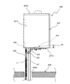
図2は上記冷温水供給ユニット200の正面図を示している。 FIG. 2 shows a front view of the cold/hot water supply unit 200.

この冷温水供給ユニット200は、室内の壁面かつ床400から所定の高さの取付位置に設置されている。図2に示すように、冷温水供給ユニット200は、直方体のケーシング231の底フレーム231aに冷媒配管接続部234と冷媒配管接続部235を設けている。この冷媒配管接続部234に冷媒配管L1(往配管)の一端が接続されると共に、冷媒配管接続部235に冷媒配管L2(復配管)の一端を接続している。この冷媒配管L1(往配管)と冷媒配管L2(復配管)は、床400に設けられた穴400aを介して床400の下側に配設され、室外機100(図1に示す)に接続される。 The cold/hot water supply unit 200 is installed at a mounting position at a predetermined height from the wall surface of the room and the floor 400. As shown in FIG. 2, the cold/hot water supply unit 200 is provided with a refrigerant pipe connecting portion 234 and a refrigerant pipe connecting portion 235 on a bottom frame 231a of a rectangular parallelepiped casing 231. One end of the refrigerant pipe L1 (outgoing pipe) is connected to the refrigerant pipe connecting portion 234, and one end of the refrigerant pipe L2 (return pipe) is connected to the refrigerant pipe connecting portion 235. The refrigerant pipe L1 (outgoing pipe) and the refrigerant pipe L2 (return pipe) are arranged below the floor 400 through a hole 400a provided in the floor 400 and connected to the outdoor unit 100 (shown in FIG. 1). To be done.

また、ケーシング231の底フレーム231aに設けられた接続口232に、一端が接続された排出ホース230によって、ケーシング231内と床下を連通している。上記排出ホース230は、排出部材の一例である。 Further, the inside of the casing 231 is communicated with the underfloor by a discharge hose 230 having one end connected to a connection port 232 provided on the bottom frame 231a of the casing 231. The discharge hose 230 is an example of a discharge member.

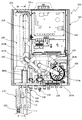
図3は上記冷温水供給ユニット200の構成を示しており、前面パネル231c(図2に示す)と天板231d(図2に示す)を外した状態を正面から見た図である。図3では、図2と同一の構成部には同一参照番号を付している。また、図3において、238,239は、水抜き栓である。 FIG. 3 shows the configuration of the cold/hot water supply unit 200, and is a front view of a state in which the front panel 231c (shown in FIG. 2) and the top plate 231d (shown in FIG. 2) are removed. In FIG. 3, the same components as those in FIG. 2 are designated by the same reference numerals. Further, in FIG. 3, reference numerals 238 and 239 are water drain plugs.

この冷温水供給ユニット200は、直方体のケーシング231と、このケーシング231の底フレーム231aに取り付けられた循環ポンプ203と、ケーシング231内の左側に設置された水熱交換器201を有している。また、ケーシング231内の水熱交換器201の右側の電装品部に、制御基板の一例としての冷温水供給ユニット用制御装置220を取り付けている。 The cold/hot water supply unit 200 includes a rectangular parallelepiped casing 231, a circulation pump 203 attached to a bottom frame 231a of the casing 231, and a water heat exchanger 201 installed on the left side in the casing 231. Further, a controller 220 for a cold/hot water supply unit, which is an example of a control board, is attached to an electric component part on the right side of the water heat exchanger 201 in the casing 231.

上記水熱交換器201は、室外機100(図1に示す)の圧縮機101から供給される高温高圧の冷媒が、冷媒配管接続部234から冷媒配管234aを介して供給される。これに対して、水熱交換器201内で熱交換した後の低温高圧の冷媒は、冷媒配管235aを介して冷媒配管接続部235から電動膨張弁104(図1に示す)に供給される。 In the water heat exchanger 201, the high temperature and high pressure refrigerant supplied from the compressor 101 of the outdoor unit 100 (shown in FIG. 1) is supplied from the refrigerant pipe connection portion 234 through the refrigerant pipe 234a. On the other hand, the low-temperature high-pressure refrigerant that has undergone heat exchange in the water heat exchanger 201 is supplied from the refrigerant pipe connection portion 235 to the electric expansion valve 104 (shown in FIG. 1) via the refrigerant pipe 235a.

上記冷媒配管234aに圧力センサ215を配設すると共に、冷媒配管235aに受液器216を配設している。 The pressure sensor 215 is arranged in the refrigerant pipe 234a, and the liquid receiver 216 is arranged in the refrigerant pipe 235a.

上記循環ポンプ203の吸入口203aと水熱交換器201の給湯口201aが給湯管236を介して接続されている。また、循環ポンプ203の吐出口203bと往きヘッダ204(図1に示す)が吐出管237を介して接続されている。さらに、水熱交換器201の吸水口201bと戻りヘッダ205(図1に示す)が吸水管240を介して接続されている。 The suction port 203a of the circulation pump 203 and the hot water supply port 201a of the water heat exchanger 201 are connected via a hot water supply pipe 236. Further, the discharge port 203b of the circulation pump 203 and the forward header 204 (shown in FIG. 1) are connected via a discharge pipe 237. Further, the water inlet 201b of the water heat exchanger 201 and the return header 205 (shown in FIG. 1) are connected via a water pipe 240.

上記構成の温調システムにおいて、室外機100(図1に示す)の圧縮機101が駆動されると、四路切換弁102が実線の切換位置の状態で圧縮機101からの高温高圧の冷媒が水熱交換器201に供給される。そして、水熱交換器201内において、戻りヘッダ205および吸水管240を介して供給される水と熱交換を行う。次に、熱交換後の低温高圧の液冷媒が水熱交換器201から電動膨張弁104(図1に示す)に送出される。一方、水熱交換器201において熱交換後の温水は、循環ポンプ203の駆動による負圧によって給湯管236を介して吸入口203aから循環ポンプ203に吸入され、吐出口203bから吐出管237および往きヘッダ204(図1に示す)を介して供給される。 In the temperature control system having the above configuration, when the compressor 101 of the outdoor unit 100 (shown in FIG. 1) is driven, the high-temperature and high-pressure refrigerant from the compressor 101 is discharged while the four-way switching valve 102 is in the switching position indicated by the solid line. It is supplied to the water heat exchanger 201. Then, in the water heat exchanger 201, heat is exchanged with the water supplied via the return header 205 and the water absorption pipe 240. Next, the low-temperature high-pressure liquid refrigerant after heat exchange is sent from the water heat exchanger 201 to the electric expansion valve 104 (shown in FIG. 1). On the other hand, the hot water after heat exchange in the water heat exchanger 201 is sucked into the circulation pump 203 from the suction port 203a via the hot water supply pipe 236 by the negative pressure generated by the driving of the circulation pump 203, and is discharged from the discharge port 203b to the discharge pipe 237 and forward. It is supplied via the header 204 (shown in FIG. 1).

上記構成の冷温水供給ユニット200によれば、図2,図3に示すように、水熱交換器201が収容されたケーシング231内と床下を排出ホース230(排出部材)により連通することによって、室内に設置された状態でケーシング231内に可燃性冷媒が急速漏洩した場合、ケーシング231内に漏洩した直後の可燃性冷媒のうちの多くは蒸発しきらずに液体のままケーシング231内から排出ホース230を介して流れ落ちて床下に速やかに排出されるので、可燃性冷媒の漏洩時に室内への冷媒漏れを防ぐことができる。したがって、室内に可燃性冷媒が滞留してガス濃度が高くなって発火などのリスクが高まるのを抑制できる。 According to the cold/hot water supply unit 200 having the above configuration, as shown in FIGS. 2 and 3, by connecting the inside of the casing 231 accommodating the water heat exchanger 201 and the underfloor by the discharge hose 230 (discharge member), When the flammable refrigerant rapidly leaks into the casing 231 in the state where it is installed indoors, most of the flammable refrigerant immediately after leaking into the casing 231 does not completely evaporate and remains as a liquid and is discharged from the inside of the casing 231 to the discharge hose 230. Since it flows down through the and is discharged immediately under the floor, it is possible to prevent the refrigerant from leaking into the room when the flammable refrigerant leaks. Therefore, it is possible to prevent the combustible refrigerant from accumulating in the room, increasing the gas concentration, and increasing the risk of ignition or the like.

また、排出部材に排出ホース230を用いることによって、ケーシング231内に漏洩した可燃性冷媒を床下に導く経路を容易に設けることができ、可撓性を有するホースを用いることで設置の自由度が高まると共に作業性が向上する。 Further, by using the discharge hose 230 as the discharge member, it is possible to easily provide a path for guiding the flammable refrigerant leaking into the casing 231 to the underfloor, and a flexible hose provides flexibility in installation. Workability is improved as it is increased.

また、上記ケーシング231内に漏洩した可燃性冷媒(特に液冷媒)がケーシング231内の底部に溜まるので、ケーシング231の下部と床下とを排出ホース230(排出部材)により連通することによって、漏洩した可燃性冷媒のうちの多くを占める液冷媒を、ケーシング231の下部から排出ホース230を介して床下に速やかに排出することができる。 Further, since the flammable refrigerant (particularly the liquid refrigerant) leaking into the casing 231 is collected at the bottom of the casing 231, the lower portion of the casing 231 and the underfloor are communicated with each other by the discharge hose 230 (exhaust member) so that they leak. The liquid refrigerant which occupies most of the combustible refrigerant can be quickly discharged from the lower portion of the casing 231 to the underfloor via the discharge hose 230.

また、上記ケーシング231内の水熱交換器201の下部に設けられた接続口232に、排出ホース230(排出部材)を接続することによって、水熱交換器201の冷媒配管接続部分から漏れ出た可燃性冷媒は、水熱交換器201の下側に流れ落ちて、下側の接続口232を介して排出ホース230により床下に排出することができる。 Also, by connecting the discharge hose 230 (discharge member) to the connection port 232 provided in the lower portion of the water heat exchanger 201 in the casing 231, the water leaked from the refrigerant pipe connection portion of the water heat exchanger 201. The flammable refrigerant flows down to the lower side of the water heat exchanger 201 and can be discharged under the floor by the discharge hose 230 via the lower connection port 232.

ここで、水熱交換器201の冷媒配管接続部分は、水熱交換器201、圧力センサ215、受液器216、冷媒配管接続部234,235の夫々に冷媒配管が接続されるロウ付け部分である。 Here, the refrigerant pipe connecting portion of the water heat exchanger 201 is a brazing portion where the refrigerant pipe is connected to each of the water heat exchanger 201, the pressure sensor 215, the liquid receiver 216, and the refrigerant pipe connecting portions 234 and 235. is there.

なお、上記第1実施形態において、後述する第6実施形態の内部カバー部材としての第2カバー部材280と同様に、ケーシング内に配置され、ケーシング内の少なくとも冷媒回路の冷媒配管接続部分を覆うと共に漏洩した可燃性冷媒をケーシング外に案内する内部カバー部材を適用してもよい。 In the first embodiment, like the second cover member 280 as the inner cover member of the sixth embodiment described later, the second cover member 280 is arranged in the casing and covers at least the refrigerant pipe connection portion of the refrigerant circuit in the casing. An internal cover member that guides the leaked flammable refrigerant to the outside of the casing may be applied.

〔第2実施形態〕
図4はこの発明の第2実施形態の温調システムの冷温水供給ユニット200の正面図を示している。この冷温水供給ユニット200は、第1実施形態の冷温水供給ユニット200と同一の構成をしており、同一構成部には同一参照番号を付している。
[Second Embodiment]
FIG. 4 is a front view of the cold/hot water supply unit 200 of the temperature control system according to the second embodiment of the present invention. The cold/hot water supply unit 200 has the same configuration as the cold/hot water supply unit 200 of the first embodiment, and the same components are designated by the same reference numerals.

また、ケーシング231内の下側に液体受け部材251を配置している。この液体受け部材251の最も低い位置が接続口232に接続されている。これによって、排出ホース230を介して冷温水供給ユニット200のケーシング231内部と床下とを連通している。 A liquid receiving member 251 is arranged on the lower side of the casing 231. The lowest position of the liquid receiving member 251 is connected to the connection port 232. As a result, the inside of the casing 231 of the cold/hot water supply unit 200 is communicated with the underfloor via the discharge hose 230.

上記液体受け部材252の底面の傾斜角度θ1[deg]を所定角度θ1min[deg]よりも大きい値に設定している。この所定角度θ1min[deg]は、ケーシング231内で可燃性冷媒が急速漏洩したときの冷媒量やケーシング231の構成などに応じて適宜決定される。ここで、傾斜角度θ1は、液体受け部材252の底面と水平面とのなす角度である。 The inclination angle θ1 [deg] of the bottom surface of the liquid receiving member 252 is set to a value larger than the predetermined angle θ1 min [deg]. The predetermined angle θ1 min [deg] is appropriately determined according to the amount of the refrigerant when the flammable refrigerant rapidly leaks in the casing 231, the configuration of the casing 231, and the like. Here, the inclination angle θ1 is an angle formed by the bottom surface of the liquid receiving member 252 and the horizontal plane.

上記第2実施形態の冷温水供給ユニット200は、第1実施形態の冷温水供給ユニット200と同一の効果を有する。 The cold/hot water supply unit 200 of the second embodiment has the same effects as the cold/hot water supply unit 200 of the first embodiment.

また、上記液体受け部材251の傾斜した底面によって、ケーシング231内で漏洩した可燃性冷媒(または冷水供給時の結露水などの液体)を、排出ホース230が接続された接続口232にスムーズに案内することができる。 Further, the inclined bottom surface of the liquid receiving member 251 smoothly guides the flammable refrigerant (or liquid such as dew condensation water when cold water is supplied) leaked in the casing 231 to the connection port 232 to which the discharge hose 230 is connected. can do.

なお、上記第2実施形態では、ケーシング231内の下側に底面が傾斜した液体受け部材251を配置したが、ケーシング231内の底フレーム231aの底面を傾斜させて、排出ホース230が接続された接続口232にスムーズに案内するようにしてもよい。また、ケーシング231内の下側に配置した液体受け部材251は、ケーシング231の底面のほぼ全てに渡って設けたが、少なくともケーシング231内の冷媒配管接続部分の下側の領域に液体受け部材を配置してもよい。 In the second embodiment described above, the liquid receiving member 251 whose bottom surface is inclined is arranged on the lower side in the casing 231, but the bottom surface of the bottom frame 231a in the casing 231 is inclined and the discharge hose 230 is connected. The connection may be smoothly guided to the connection port 232. Further, although the liquid receiving member 251 arranged on the lower side in the casing 231 is provided over almost the entire bottom surface of the casing 231, the liquid receiving member is provided at least in the region below the refrigerant pipe connecting portion in the casing 231. You may arrange.

なお、上記第2実施形態において、後述する第6実施形態の内部カバー部材としての第2カバー部材280と同様に、ケーシング内に配置され、ケーシング内の少なくとも冷媒回路の冷媒配管接続部分を覆うと共に漏洩した可燃性冷媒をケーシング外に案内する内部カバー部材を適用してもよい。 In the second embodiment described above, like the second cover member 280 as the inner cover member of the sixth embodiment described later, the second cover member 280 is arranged in the casing and covers at least the refrigerant pipe connection portion of the refrigerant circuit in the casing. An internal cover member that guides the leaked flammable refrigerant to the outside of the casing may be applied.

〔第3実施形態〕
図5はこの発明の第3実施形態の温調システムの冷温水供給ユニット200の正面図を示している。この冷温水供給ユニット200は、第1実施形態の冷温水供給ユニット200と同一の構成をしており、同一構成部には同一参照番号を付している。
[Third Embodiment]
FIG. 5 shows a front view of the cold/hot water supply unit 200 of the temperature control system according to the third embodiment of the present invention. The cold/hot water supply unit 200 has the same configuration as the cold/hot water supply unit 200 of the first embodiment, and the same components are designated by the same reference numerals.

この第3実施形態の冷温水供給ユニット200は、図5に示すように、ケーシング231の下面側から床面に延びる置台250を備えている。上記置台250は、冷媒配管L1,L2および排出ホース230の一部を収容する箱状の通路を構成している。この冷媒配管L1,L2は、床400に設けられた穴400aを介して床400の下側に配設され、室外機100(図1に示す)に接続される。 As shown in FIG. 5, the cold/hot water supply unit 200 of the third embodiment includes a mounting table 250 extending from the lower surface side of the casing 231 to the floor surface. The mounting table 250 constitutes a box-shaped passage for accommodating part of the refrigerant pipes L1 and L2 and the discharge hose 230. The refrigerant pipes L1 and L2 are arranged below the floor 400 through holes 400a provided in the floor 400 and are connected to the outdoor unit 100 (shown in FIG. 1).

上記排出ホース230と置台250で排出部材を構成している。 The discharge hose 230 and the stand 250 constitute a discharge member.

また、置台250内の下側に液体受け部材252を配置している。この液体受け部材252の最も低い位置に設けられた接続口252aに排出ホース230の上端を接続することによって、置台250と排出ホース230を介して冷温水供給ユニット200のケーシング231内部と床下とを連通している。 Further, a liquid receiving member 252 is arranged on the lower side of the table 250. By connecting the upper end of the discharge hose 230 to the connection port 252a provided at the lowest position of the liquid receiving member 252, the inside of the casing 231 of the cold/hot water supply unit 200 and the underfloor are connected via the stand 250 and the discharge hose 230. It is in communication.

上記液体受け部材252の底面の傾斜角度θ2[deg]を所定角度θ2min[deg]よりも大きい値に設定している。この所定角度θ2min[deg]は、冷温水供給ユニット200から可燃性冷媒が急速漏洩したときの冷媒量やケーシング231および置台250の構成などに応じて適宜決定される。 The inclination angle θ2[deg] of the bottom surface of the liquid receiving member 252 is set to a value larger than the predetermined angle θ2min[deg]. The predetermined angle θ2 min [deg] is appropriately determined according to the amount of the refrigerant when the combustible refrigerant rapidly leaks from the cold/hot water supply unit 200, the configurations of the casing 231 and the mounting table 250, and the like.

上記第3実施形態では、置台250内の下側に液体受け部材252を配置したが、液体受け部材または排出ホースの少なくとも一方を備えない構成でもよい。この場合でも、箱状の通路を構成する置台によりケーシング内から漏洩した可燃性冷媒を床下に案内することができる。 In the third embodiment described above, the liquid receiving member 252 is arranged on the lower side of the mounting table 250, but it may be configured not to include at least one of the liquid receiving member and the discharge hose. Even in this case, the flammable refrigerant leaked from the inside of the casing can be guided to the underfloor by the mounting table forming the box-shaped passage.

上記第3実施形態の冷温水供給ユニット200は、第1実施形態の冷温水供給ユニット200と同一の効果を有する。 The cold/hot water supply unit 200 of the third embodiment has the same effects as the cold/hot water supply unit 200 of the first embodiment.

また、壁面に設置するタイプの冷温水供給ユニット200において、ケーシング231下部に箱状の通路として置台250を用いることによって、壁面に設置したケーシング231の下側空間(配管などが敷設される空間)を置台250で覆って、美観を損ねることなく、ケーシング231内に漏洩した可燃性冷媒を床下に導く通路を形成できる。 Further, in the cold/hot water supply unit 200 of the type installed on the wall surface, by using the mounting table 250 as a box-shaped passage under the casing 231, a lower space of the casing 231 installed on the wall surface (a space where pipes and the like are laid) It is possible to form a passage that guides the flammable refrigerant leaking into the casing 231 to the underfloor by covering the stand with the stand 250 without spoiling the appearance.

また、上記置台250内に配置された液体受け部材252により、漏洩した可燃性冷媒(または冷水供給時の結露水などの液体)を、排出ホース230(排出部材)が接続された接続口252aに確実に案内することができる。 In addition, the liquid receiving member 252 disposed in the mounting table 250 allows the leaked combustible refrigerant (or liquid such as dew condensation water when cold water is supplied) to the connection port 252a to which the discharge hose 230 (discharge member) is connected. You can be sure to guide.

また、上記液体受け部材252の傾斜した底面によって、ケーシング231下部から漏洩した可燃性冷媒(または冷水供給時の結露水などの液体)を、排出ホース230が接続された接続口252aにスムーズに案内することができる。 Further, the inclined bottom surface of the liquid receiving member 252 smoothly guides the flammable refrigerant (or liquid such as dew condensation water when cold water is supplied) leaked from the lower portion of the casing 231 to the connection port 252a to which the discharge hose 230 is connected. can do.

また、上記ケーシング231外において、冷媒配管L1,L2が接続された冷媒配管接続部234,235から可燃性冷媒が漏れ出ても、置台250内で受けて排出ホース230により床下に排出することができ、より安全性が高まる。 Further, outside the casing 231, even if the flammable refrigerant leaks from the refrigerant pipe connecting portions 234 and 235 to which the refrigerant pipes L1 and L2 are connected, it can be received inside the stand 250 and discharged under the floor by the discharge hose 230. You can do it, and it will be more secure.

なお、上記第3実施形態において、後述する第6実施形態の内部カバー部材としての第2カバー部材280と同様に、ケーシング内に配置され、ケーシング内の少なくとも冷媒回路の冷媒配管接続部分を覆うと共に漏洩した可燃性冷媒をケーシング外に案内する内部カバー部材を適用してもよい。 In addition, in the said 3rd Embodiment, it arrange|positions in a casing like the 2nd cover member 280 as an internal cover member of 6th Embodiment mentioned later, and covers at least the refrigerant|coolant piping connection part of a refrigerant circuit in a casing. An internal cover member that guides the leaked flammable refrigerant to the outside of the casing may be applied.

〔第4実施形態〕
図6はこの発明の第4実施形態の温調システムの冷温水供給ユニット200の構成を示す図を示している。この冷温水供給ユニット200は、排出ホース230の接続部分と液体受け部材260を除いて第1実施形態の冷温水供給ユニット200と同一の構成をしており、同一構成部には同一参照番号を付している。
[Fourth Embodiment]
FIG. 6 is a diagram showing the configuration of the cold/hot water supply unit 200 of the temperature control system according to the fourth embodiment of the present invention. The cold/hot water supply unit 200 has the same configuration as the cold/hot water supply unit 200 of the first embodiment except for the connection portion of the discharge hose 230 and the liquid receiving member 260, and the same components are designated by the same reference numerals. Attached.

この第4実施形態の冷温水供給ユニット200は、図6に示すように、ケーシング231内の水熱交換器201よりも下側に液体受け部材260を配置している。 In the cold/hot water supply unit 200 of the fourth embodiment, as shown in FIG. 6, the liquid receiving member 260 is arranged below the water heat exchanger 201 in the casing 231.

この液体受け部材260の接続口260aに、排出ホース230の上端が接続されている。この液体受け部材260で受けた結露水や漏洩冷媒などの液体を排出ホース230の接続口260aに案内する。排出ホース230は、排出部材の一例である。 The upper end of the discharge hose 230 is connected to the connection port 260a of the liquid receiving member 260. The liquid such as dew condensation water and leakage refrigerant received by the liquid receiving member 260 is guided to the connection port 260a of the discharge hose 230. The discharge hose 230 is an example of a discharge member.

上記第4実施形態の冷温水供給ユニット200は、第1実施形態の冷温水供給ユニット200と同一の効果を有する。 The cold/hot water supply unit 200 of the fourth embodiment has the same effects as the cold/hot water supply unit 200 of the first embodiment.

また、上記ケーシング231内に配置された液体受け部材260により、漏洩した可燃性冷媒(または冷水供給時の結露水などの液体)を、排出ホース230(排出部材)が接続された接続口260aに確実に案内することができる。 In addition, the liquid receiving member 260 arranged in the casing 231 allows the leaked combustible refrigerant (or liquid such as dew condensation water when cold water is supplied) to the connection port 260a to which the discharge hose 230 (discharge member) is connected. You can be sure to guide.

なお、上記液体受け部材260の底面を傾斜させて、漏洩した可燃性冷媒などの液体を、排出ホース230(排出部材)が接続された接続口252aにスムーズに案内するようにしてもよい。 The bottom surface of the liquid receiving member 260 may be inclined so that the leaked liquid such as flammable refrigerant is smoothly guided to the connection port 252a to which the discharge hose 230 (discharge member) is connected.

なお、上記第4実施形態において、後述する第6実施形態の内部カバー部材としての第2カバー部材280と同様に、ケーシング内に配置され、ケーシング内の少なくとも冷媒回路の冷媒配管接続部分を覆うと共に漏洩した可燃性冷媒をケーシング外に案内する内部カバー部材を適用してもよい。 In the fourth embodiment, similarly to the second cover member 280 as the inner cover member of the sixth embodiment described below, the second cover member 280 is arranged in the casing and covers at least the refrigerant pipe connection portion of the refrigerant circuit in the casing. An internal cover member that guides the leaked flammable refrigerant to the outside of the casing may be applied.

〔第5実施形態〕
図7はこの発明の第5実施形態の温調システムの冷温水供給ユニット200の構成を示している。この冷温水供給ユニット200は、排出ホース230の接続部分と第1カバー部材270を除いて第1実施形態の冷温水供給ユニット200と同一の構成をしており、同一構成部には同一参照番号を付している。
[Fifth Embodiment]
FIG. 7 shows the configuration of the cold/hot water supply unit 200 of the temperature control system according to the fifth embodiment of the present invention. The cold/hot water supply unit 200 has the same configuration as the cold/hot water supply unit 200 of the first embodiment except for the connection portion of the discharge hose 230 and the first cover member 270, and the same components are designated by the same reference numerals. Is attached.

この第5実施形態の冷温水供給ユニット200は、図7に示すように、ケーシング231の底フレーム231aに、冷媒配管接続部234と冷媒配管接続部235を覆うように第1カバー部材270を取り付けている。この第1カバー部材270は、底フレーム231aの接続口241に接続されており、冷媒配管接続部234に接続された冷媒配管L1および冷媒配管接続部235に接続された冷媒配管L2が貫通する穴270a,270bを有する。また、第1カバー部材270は、排出ホース230の上端が接続された接続穴270cを有する。なお、第1カバー部材270の穴270aと冷媒配管L1との隙間、および、第1カバー部材270の穴270bと冷媒配管L2との隙間は、シール剤などにより密閉している。 In the cold/hot water supply unit 200 of the fifth embodiment, as shown in FIG. 7, a first cover member 270 is attached to the bottom frame 231a of the casing 231 so as to cover the refrigerant pipe connecting portion 234 and the refrigerant pipe connecting portion 235. ing. The first cover member 270 is connected to the connection port 241 of the bottom frame 231a, and is a hole through which the refrigerant pipe L1 connected to the refrigerant pipe connection portion 234 and the refrigerant pipe L2 connected to the refrigerant pipe connection portion 235 pass. It has 270a and 270b. The first cover member 270 also has a connection hole 270c to which the upper end of the discharge hose 230 is connected. The gap between the hole 270a of the first cover member 270 and the refrigerant pipe L1 and the gap between the hole 270b of the first cover member 270 and the refrigerant pipe L2 are sealed with a sealant or the like.

上記排出ホース230と第1カバー部材270で排出部材を構成している。 The discharge hose 230 and the first cover member 270 form a discharge member.

なお、第5実施形態の冷温水供給ユニット200において、冷温水供給ユニット用制御装置220が取り付けられた電装品部を覆う基板カバー部材221を取り付けてもよい。これにより、ケーシング231内に漏れた冷媒に対して電装品部の発火点を隔離することができ、安全性が向上する。 In addition, in the cold/hot water supply unit 200 of the fifth embodiment, a substrate cover member 221 that covers the electrical component part to which the cold/hot water supply unit control device 220 is attached may be attached. Thereby, the ignition point of the electric component part can be isolated from the refrigerant leaking into the casing 231, and the safety is improved.

また、図8は図7のVII−VII線から見た第1カバー部材270を含む要部の断面図を示している。この第1カバー部材270は、前側カバー部271と後側カバー部272を有する。前側カバー部271の上端にフック271aを設けている。また、後側カバー部272の上端にフック272aを設けている。 Further, FIG. 8 shows a cross-sectional view of the main part including the first cover member 270 as seen from the line VII-VII of FIG. 7. The first cover member 270 has a front cover portion 271 and a rear cover portion 272. A hook 271a is provided on the upper end of the front cover portion 271. Further, a hook 272a is provided at the upper end of the rear cover part 272.

ケーシング231の底フレーム231aに設けられた長穴状の接続口241に冷媒配管234a,235a(図8では235aのみを示す)を挿通している。この接続口241の対向する縁の一方に前側カバー部271のフック271aを係止すると共に、接続口241の対向する縁の他方に後側カバー部272のフック272aを係止している。 Refrigerant pipes 234a and 235a (only 235a is shown in FIG. 8) are inserted through elongated connection ports 241 provided on the bottom frame 231a of the casing 231. The hook 271a of the front cover portion 271 is locked to one of the facing edges of the connection opening 241, and the hook 272a of the rear cover portion 272 is locked to the other opposite edge of the connection opening 241.

上記構成の冷温水供給ユニット200によれば、ケーシング231内の冷媒配管接続部分よりも下側に設けられた接続口241に排出部材(第1カバー部材270と排出ホース230)が接続され、ケーシング231内に漏洩した可燃性冷媒を接続口241から第1カバー部材270と排出ホース230によりケーシング231外に排出することによって、室内に設置された状態でケーシング231内に可燃性冷媒が急速漏洩した場合、ケーシング231内に漏洩した直後の可燃性冷媒のうちの多くは蒸発しきらずに液体のままであるので、液体の可燃性冷媒がケーシング231内から第1カバー部材270と排出ホース230を介して流れ落ちて床下に速やかに排出することが可能になる。したがって、可燃性冷媒の漏洩時に室内への冷媒漏れを防ぐことができ、室内に可燃性冷媒が滞留してガス濃度が高くなって発火などのリスクが高まるのを抑制できる。 According to the cold/hot water supply unit 200 having the above-described configuration, the discharge member (the first cover member 270 and the discharge hose 230) is connected to the connection port 241 provided below the refrigerant pipe connection portion in the casing 231, and the casing By discharging the flammable refrigerant leaking into the inside of the inside of the casing 231, from the connection port 241 to the outside of the casing 231 by the first cover member 270 and the discharge hose 230, the flammable inside of the casing 231 rapidly leaked into the casing 231. In this case, most of the combustible refrigerant immediately after leaking into the casing 231 does not evaporate and remains as a liquid, so that the liquid combustible refrigerant passes through the first cover member 270 and the discharge hose 230 from inside the casing 231. It will be possible to quickly discharge it under the floor. Therefore, when the flammable refrigerant leaks, it is possible to prevent the refrigerant from leaking into the room, and it is possible to prevent the flammable refrigerant from staying in the room and increasing the gas concentration, thereby increasing the risk of ignition or the like.

なお、気化した上記可燃性冷媒が空気よりも重い場合、気体の可燃性冷媒も下方に流れてケーシング231内から第1カバー部材270と排出ホース230を介して下方に排出される。 When the vaporized flammable refrigerant is heavier than air, the gaseous flammable refrigerant also flows downward and is discharged downward from the casing 231 via the first cover member 270 and the discharge hose 230.

また、上記ケーシング231内に漏洩した可燃性冷媒(特に液冷媒)がケーシング231内の底部に溜まるので、ケーシング231の下部からの漏洩冷媒を第1カバー部材270により排出することで、ケーシング231内に漏洩した可燃性冷媒のうちの多くを占める液冷媒を、ケーシング231の下部から第1カバー部材270と排出ホース230を介して床下に速やかに排出することができる。 In addition, since flammable refrigerant (particularly liquid refrigerant) that leaks into the casing 231 collects at the bottom of the casing 231, the leakage of refrigerant from the lower portion of the casing 231 is discharged by the first cover member 270. The liquid refrigerant that occupies most of the flammable refrigerant that has leaked to the bottom can be quickly discharged from the lower part of the casing 231 to the underfloor via the first cover member 270 and the discharge hose 230.

また、上記第1カバー部材270がケーシング231外の冷媒配管接続部234,235を覆っていることによって、そのケーシング231外の冷媒配管接続部234,235から可燃性冷媒が漏れ出ても第1カバー部材270内で受けて排出することができ、より安全性が高まる。 In addition, since the first cover member 270 covers the refrigerant pipe connecting portions 234 and 235 outside the casing 231, even if the flammable refrigerant leaks from the refrigerant pipe connecting portions 234 and 235 outside the casing 231, the first cover member 270 is Since it can be received and discharged in the cover member 270, the safety is further enhanced.

また、上記ケーシング231内かつ第1カバー部材270よりも上側に冷温水供給ユニット用制御装置220(制御基板)を配置することによって、ケーシング231内の底部に漏れた可燃性冷媒に対して冷温水供給ユニット用制御装置220が有するような発火点を上方に引き離すことができ、安全性が向上する。 In addition, by arranging the controller 220 (control board) for the cold/hot water supply unit in the casing 231 and above the first cover member 270, the combustible refrigerant leaking to the bottom of the casing 231 is cooled against hot/cold water. The ignition point that the supply unit control device 220 has can be pulled upward, and safety is improved.

また、上記水熱交換器201が収容されたケーシング231内と床下を第1カバー部材270,排出ホース230(排出部材)により連通することによって、室内に設置された状態でケーシング231内に可燃性冷媒が急速漏洩した場合、ケーシング231内に漏洩した直後の可燃性冷媒のうちの多くは蒸発しきらずに液体のままケーシング231内から排出ホース230を介して流れ落ちて床下に速やかに排出される。 Further, the inside of the casing 231 accommodating the water heat exchanger 201 and the underfloor are communicated with each other by the first cover member 270 and the discharge hose 230 (discharge member), so that the combustible inside the casing 231 is installed in the room. When the refrigerant rapidly leaks, most of the combustible refrigerant immediately after leaking into the casing 231 does not evaporate and remains as a liquid from the inside of the casing 231 through the discharge hose 230 and is quickly discharged under the floor.

また、排出部材に排出ホース230を用いることによって、ケーシング231内に漏洩した可燃性冷媒を床下に導く経路を容易に設けることができ、可撓性を有するホースを用いることで設置の自由度が高まると共に作業性が向上する。 Further, by using the discharge hose 230 as the discharge member, it is possible to easily provide a path for guiding the flammable refrigerant leaking into the casing 231 to the underfloor, and a flexible hose provides flexibility in installation. The workability is improved with the increase.

また、上記ケーシング231内に漏洩した可燃性冷媒(特に液冷媒)がケーシング231内の底部に溜まるので、ケーシング231の下部と床下とを第1カバー部材270,排出ホース230(排出部材)により連通することによって、漏洩した可燃性冷媒のうちの多くを占める液冷媒を、ケーシング231の下部から第1カバー部材270,排出ホース230を介して床下に速やかに排出することができる。 In addition, since the flammable refrigerant (particularly the liquid refrigerant) leaking into the casing 231 is collected at the bottom of the casing 231, the lower portion of the casing 231 and the underfloor are communicated by the first cover member 270 and the discharge hose 230 (discharge member). By doing so, the liquid refrigerant that occupies most of the leaked combustible refrigerant can be quickly discharged from the lower portion of the casing 231 to the underfloor via the first cover member 270 and the discharge hose 230.

なお、第1カバー部材270に液体を案内するように、ケーシング231内の底部を傾斜させてもよい。この場合、ケーシング231の傾斜した底面によって、ケーシング231内で漏洩した可燃性冷媒(または冷水供給時の結露水などの液体)を接続口241にスムーズに案内することができる。 The bottom of the casing 231 may be inclined so as to guide the liquid to the first cover member 270. In this case, the inclined bottom surface of the casing 231 can smoothly guide the flammable refrigerant (or the liquid such as dew condensation water at the time of supplying cold water) leaked in the casing 231 to the connection port 241.

また、上記第5実施形態の冷温水供給ユニット200において、第2実施形態の図4に示す液体受け部材251をケーシング231内の下側に配置してもよい。この場合、液体受け部材251の傾斜した底面によって、ケーシング231内で漏洩した可燃性冷媒(または冷水供給時の結露水などの液体)を接続口241にスムーズに案内することができる。 Further, in the cold/hot water supply unit 200 of the fifth embodiment, the liquid receiving member 251 shown in FIG. 4 of the second embodiment may be arranged below the casing 231. In this case, the inclined bottom surface of the liquid receiving member 251 can smoothly guide the flammable refrigerant (or liquid such as dew condensation water when cold water is supplied) leaked in the casing 231 to the connection port 241.

なお、上記第5実施形態において、後述する第6実施形態の内部カバー部材としての第2カバー部材280と同様に、ケーシング内に配置され、ケーシング内の少なくとも冷媒回路の冷媒配管接続部分を覆うと共に漏洩した可燃性冷媒をケーシング外に案内する内部カバー部材を適用してもよい。 In addition, in the said 5th Embodiment, it arrange|positions in a casing like the 2nd cover member 280 as an internal cover member of 6th Embodiment mentioned later, and covers at least the refrigerant|coolant piping connection part of a refrigerant circuit in a casing. An internal cover member that guides the leaked flammable refrigerant to the outside of the casing may be applied.

〔第6実施形態〕
図9はこの発明の第6実施形態の温調システムの冷温水供給ユニット200の構成を示している。この第6実施形態の冷温水供給ユニット200は、第2カバー部材280を除いて第5実施形態の冷温水供給ユニット200と同一の構成をしており、同一構成部には同一参照番号を付している。
[Sixth Embodiment]
FIG. 9 shows the configuration of the cold/hot water supply unit 200 of the temperature control system according to the sixth embodiment of the present invention. The cold/hot water supply unit 200 of the sixth embodiment has the same configuration as the cold/hot water supply unit 200 of the fifth embodiment except for the second cover member 280, and the same components are designated by the same reference numerals. doing.

この第6実施形態の冷温水供給ユニット200は、図9に示すように、ケーシング231の底フレーム231aに冷媒配管接続部234と冷媒配管接続部235を覆う第1カバー部材270を取り付けている。 In the cold/hot water supply unit 200 of the sixth embodiment, as shown in FIG. 9, a first cover member 270 that covers the refrigerant pipe connecting portion 234 and the refrigerant pipe connecting portion 235 is attached to the bottom frame 231a of the casing 231.

また、ケーシング231内に、冷媒回路の冷媒配管接続部分を覆う第2カバー部材280を取り付けている。この第2カバー部材280は、内部カバー部材の一例である。 In addition, a second cover member 280 that covers the refrigerant pipe connection portion of the refrigerant circuit is installed in the casing 231. The second cover member 280 is an example of an inner cover member.

この第2カバー部材280は、断熱材(例えば発泡樹脂)からなり、本体部280aと、本体部280aの下端から下方に延びる案内部280bを有する。第2カバー部材280の本体部280aは、水熱交換器201の前面側の一部(圧力センサ215,受液器216を含む)すなわち冷媒配管接続部分を覆っている。 The second cover member 280 is made of a heat insulating material (for example, foamed resin), and has a main body 280a and a guide 280b extending downward from the lower end of the main body 280a. The main body portion 280a of the second cover member 280 covers a part of the front surface side of the water heat exchanger 201 (including the pressure sensor 215 and the liquid receiver 216), that is, the refrigerant pipe connection portion.

図10は図9のIX−IX線から見た断面図を示しており、図9と同一の構成部には同一参照番号を付している。 FIG. 10 shows a sectional view taken along the line IX-IX in FIG. 9, and the same components as those in FIG. 9 are designated by the same reference numerals.

図10に示すように、ケーシング231内の後面側に背面断熱部材290を取り付けている。この背面断熱部材290に設けられた縦長の凹部290a内に水熱交換器201が嵌め込まれている。 As shown in FIG. 10, a rear surface heat insulating member 290 is attached to the rear surface side in the casing 231. The water heat exchanger 201 is fitted in a vertically elongated recess 290a provided in the rear heat insulating member 290.

ここで、圧力センサ215が配設された冷媒配管234a(図3に示す)や、受液器216が配設された冷媒配管235a(図3に示す)において、ロウ付けされた配管接続部分から可燃性冷媒が漏洩した場合、図10の矢印に示すように、漏洩した直後の可燃性冷媒のうちの多くを占める液冷媒は、第2カバー部材280の本体部280a内を下方に流れて、本体部280aの下端から案内部280bを介して第1カバー部材270内に案内される。この後、第1カバー部材270の接続穴270c(図7に示す)に接続された排出ホース230を介して床下に排出される。 Here, in the refrigerant pipe 234a (shown in FIG. 3) in which the pressure sensor 215 is arranged and the refrigerant pipe 235a (shown in FIG. 3) in which the liquid receiver 216 is arranged, from the brazed pipe connection portion When the flammable refrigerant leaks, as shown by the arrow in FIG. 10, the liquid refrigerant that occupies most of the flammable refrigerant immediately after leaking flows downward in the main body portion 280a of the second cover member 280, It is guided from the lower end of the main body 280a into the first cover member 270 via the guide 280b. After that, it is discharged under the floor via the discharge hose 230 connected to the connection hole 270c (shown in FIG. 7) of the first cover member 270.

上記排出ホース230と第1カバー部材270で排出部材を構成している。第1カバー部材270は、前側カバー部271と後側カバー部272を有する。 The discharge hose 230 and the first cover member 270 form a discharge member. The first cover member 270 has a front cover portion 271 and a rear cover portion 272.

図11は図9の第1カバー部材270を含む要部の拡大断面図を示している。図11において、第5実施形態の図8と同一の構成部には同一参照番号を付している。 FIG. 11 is an enlarged cross-sectional view of the main part including the first cover member 270 of FIG. 11, the same components as those in FIG. 8 of the fifth embodiment are designated by the same reference numerals.

図11に示すように、上方の配管接続部分から漏洩した可燃性冷媒は、第2カバー部材280の案内部280bに案内されて、底フレーム231aに設けられた接続口241を介して第1カバー部材270内に流れ落ちる。 As shown in FIG. 11, the flammable refrigerant that has leaked from the upper pipe connection portion is guided by the guide portion 280b of the second cover member 280 and the first cover via the connection port 241 provided in the bottom frame 231a. It flows down into member 270.

図12は上記冷温水供給ユニット200の分解斜視図を示している。図12では、前面パネル231c(図2に示す)と天板231d(図2に示す)を省略している。 FIG. 12 shows an exploded perspective view of the cold/hot water supply unit 200. In FIG. 12, the front panel 231c (shown in FIG. 2) and the top plate 231d (shown in FIG. 2) are omitted.

上記冷温水供給ユニット200は、図12に示すように、底フレーム231aと、その底フレーム231aの背面側と左側面および右側面を囲う背面パネル231bと、背面パネル231bに嵌め込まれた背面断熱部材290と、背面断熱部材290の左側に設けられた縦長の凹部290a内に嵌め込まれた水熱交換器201と、背面断熱部材290の右側に設けられた凹部290b内に後面側が嵌め込まれた膨張タンク202と、膨張タンク202の前面側を覆う前面断熱部材295と、その前面断熱部材295の前面に取り付けられた冷温水供給ユニット用制御装置220と、冷媒回路の冷媒配管接続部分を覆う第2カバー部材280と、底フレーム231aの下側に取り付けられた第1カバー部材270(前側カバー部271,後側カバー部272)とを有する。 As shown in FIG. 12, the cold/hot water supply unit 200 includes a bottom frame 231a, a back panel 231b surrounding the bottom frame 231a on the back side, left side and right side, and a back heat insulating member fitted to the back panel 231b. 290, a water heat exchanger 201 fitted in a vertically elongated recess 290a provided on the left side of the back heat insulating member 290, and an expansion tank having a rear surface fitted in a recess 290b provided on the right side of the back heat insulating member 290. 202, a front heat insulating member 295 that covers the front side of the expansion tank 202, a controller 220 for the hot and cold water supply unit attached to the front surface of the front heat insulating member 295, and a second cover that covers the refrigerant pipe connection portion of the refrigerant circuit. It has a member 280 and a first cover member 270 (front cover part 271, rear cover part 272) attached to the bottom side of the bottom frame 231a.

また、図13は上記冷温水供給ユニット200の底フレーム231aに背面断熱部材290と第1,第2カバー部材270,280が取り付けられた状態の斜視図を示している。図13において、図9と同一構成部には同一参照番号を付している。 FIG. 13 is a perspective view showing a state where the back surface heat insulating member 290 and the first and second cover members 270 and 280 are attached to the bottom frame 231a of the cold/hot water supply unit 200. 13, the same components as those in FIG. 9 are designated by the same reference numerals.

また、図14は上記冷温水供給ユニット200の底フレーム231aに背面断熱部材290と第1,第2カバー部材270,280が取り付けられた状態の正面図を示している。図14において、図9と同一構成部には同一参照番号を付している。 Further, FIG. 14 is a front view showing a state in which the back heat insulating member 290 and the first and second cover members 270 and 280 are attached to the bottom frame 231a of the cold/hot water supply unit 200. 14, the same components as those in FIG. 9 are designated by the same reference numerals.

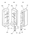
また、図15(a)は上記第2カバー部材280の右斜め前方かつ斜め上方から見た斜視図を示している。また、図15(b)は上記第2カバー部材280の右斜め後方かつ斜め上方から見た斜視図を示している。また、図15(c)は上記第2カバー部材280の左斜め後方かつ斜め上方から見た斜視図を示している。 Further, FIG. 15A shows a perspective view of the second cover member 280 as seen from diagonally right front and diagonally above. Further, FIG. 15(b) shows a perspective view of the second cover member 280 as seen from diagonally right rear and diagonally upper. Further, FIG. 15C shows a perspective view of the second cover member 280 as seen from diagonally left rear and diagonally upper.

図15(a)〜図15(c)に示すように、第2カバー部材280の本体部280aは、後面側が開口する縦長のドーム形状をしている。この本体部280aの下端かつ開口側の縁から下方に延びる長方形状の案内部280bは、上辺を除く各辺に周壁281,282,283を設けている。 As shown in FIGS. 15(a) to 15(c), the main body portion 280a of the second cover member 280 has a vertically long dome shape with an opening on the rear surface side. The rectangular guide portion 280b extending downward from the lower end of the main body portion 280a and the edge on the opening side is provided with peripheral walls 281, 282, 283 on each side except the upper side.

上記第6実施形態の冷温水供給ユニット200は、第5実施形態の冷温水供給ユニット200と同様の効果を有する。 The cold/hot water supply unit 200 of the sixth embodiment has the same effects as the cold/hot water supply unit 200 of the fifth embodiment.

また、上記構成の冷温水供給ユニット200によれば、水熱交換器201が収容されたケーシング231内に配置された第2カバー部材280(内部カバー部材)により、少なくとも冷媒回路の冷媒配管接続部分を覆うと共に漏洩した可燃性冷媒をケーシング231外に案内することによって、ケーシング231内に可燃性冷媒が急速漏洩した場合、第2カバー部材280により覆われた少なくとも冷媒回路の冷媒配管接続部分から漏洩した直後の可燃性冷媒のうちの多くは液体のままであるので、第2カバー部材280に案内されて排出される。したがって、この冷温水供給ユニット200が室内に設置された環境においても、第2カバー部材280により案内された可燃性冷媒がケーシング231内から室内へ漏れないように処理することが可能になる。このように、可燃性冷媒の漏洩時に室内への冷媒漏れを防ぐことができ、室内に可燃性冷媒が滞留してガス濃度が高くなって発火などのリスクが高まるのを抑制できる。 Further, according to the cold/hot water supply unit 200 having the above configuration, at least the refrigerant pipe connection portion of the refrigerant circuit is provided by the second cover member 280 (internal cover member) arranged in the casing 231 in which the water heat exchanger 201 is housed. When the flammable refrigerant rapidly leaks into the casing 231 by guiding the leaked flammable refrigerant to the outside of the casing 231, the leaked flammable refrigerant leaks from at least the refrigerant pipe connection portion of the refrigerant circuit covered by the second cover member 280. Most of the flammable refrigerant immediately after the operation remains a liquid, and is guided and discharged by the second cover member 280. Therefore, even in an environment where the cold/hot water supply unit 200 is installed indoors, it is possible to treat the flammable refrigerant guided by the second cover member 280 so as not to leak from the inside of the casing 231 to the indoors. In this way, when the flammable refrigerant leaks, it is possible to prevent the refrigerant from leaking into the room, and it is possible to prevent the flammable refrigerant from staying in the room and increasing the gas concentration and increasing the risk of ignition or the like.

また、上記水熱交換器201を第2カバー部材280により覆うことによって、水熱交換器201の冷媒配管接続部分や水熱交換器201自体から可燃性冷媒が漏洩しても、ケーシング231内に拡散することなく、ケーシング231外に排出できる。 In addition, by covering the water heat exchanger 201 with the second cover member 280, even if the flammable refrigerant leaks from the refrigerant pipe connecting portion of the water heat exchanger 201 or the water heat exchanger 201 itself, the water heat exchanger 201 is introduced into the casing 231. It can be discharged to the outside of the casing 231 without being diffused.

また、上記ケーシング231内の冷媒回路の全てを第2カバー部材280第2カバー部材280により覆うことによって、ケーシング231内の冷媒回路のどの箇所から可燃性冷媒が漏洩しても、ケーシング231内に拡散することなく、ケーシング231外に確実に排出できる。 In addition, by covering the entire refrigerant circuit in the casing 231 with the second cover member 280 and the second cover member 280, even if the flammable refrigerant leaks from any place in the refrigerant circuit in the casing 231, the combustible refrigerant will not be discharged into the casing 231. It can be reliably discharged to the outside of the casing 231 without diffusion.

また、断熱材からなる第2カバー部材280を用いて、水熱交換器201の少なくとも一部を覆うことによって、水熱交換器201を断熱する断熱材を兼ねることができ、断熱効果を高めることができる。 Further, by covering at least a part of the water heat exchanger 201 with the second cover member 280 made of a heat insulating material, it is possible to serve also as a heat insulating material for insulating the water heat exchanger 201, thereby enhancing the heat insulating effect. You can

また、上記第2カバー部材280の案内部280bがケーシング231に設けられた接続口241に係合することで、第2カバー部材280を簡単に位置決めできると共に、接続口241に漏洩した可燃性冷媒を案内することができる。 Further, by engaging the guide portion 280b of the second cover member 280 with the connection port 241 provided in the casing 231, the second cover member 280 can be easily positioned and the flammable refrigerant leaked to the connection port 241. Can guide you.

なお、上記カバー部材280の案内部280bを、ケーシング231の底フレーム231aに設けられた接続口241に係合するように構成してもよい。これにより、漏洩した冷媒の接続口241への案内と共に、カバー部材280の位置決めが可能になる。 The guide portion 280b of the cover member 280 may be configured to engage with the connection port 241 provided in the bottom frame 231a of the casing 231. As a result, the leaked refrigerant can be guided to the connection port 241, and the cover member 280 can be positioned.

〔第7実施形態〕
図16はこの発明の第7実施形態の温調システムの冷温水供給ユニット200の構成を示している。この冷温水供給ユニット200は、第1カバー部材275を除いて第5実施形態の冷温水供給ユニット200と同一の構成をしており、同一構成部には同一参照番号を付している。
[Seventh Embodiment]
FIG. 16 shows the configuration of the cold/hot water supply unit 200 of the temperature control system according to the seventh embodiment of the present invention. This cold/hot water supply unit 200 has the same configuration as the cold/hot water supply unit 200 of the fifth embodiment except for the first cover member 275, and the same components are designated by the same reference numerals.

この第7実施形態の冷温水供給ユニット200は、図16に示すように、ケーシング231の底フレーム231aに冷媒配管接続部234と冷媒配管接続部235を覆う第1カバー部材275を取り付けている。この第1カバー部材275は、冷媒配管接続部234に接続された冷媒配管L1および冷媒配管接続部235に接続された冷媒配管L2が貫通する穴275a,275bを有する。また、第1カバー部材275は、排出ホース230の上端が接続された接続穴275cを有する。 In the cold/hot water supply unit 200 of the seventh embodiment, as shown in FIG. 16, a first cover member 275 that covers the refrigerant pipe connecting portion 234 and the refrigerant pipe connecting portion 235 is attached to the bottom frame 231a of the casing 231. The first cover member 275 has holes 275a and 275b through which the refrigerant pipe L1 connected to the refrigerant pipe connection portion 234 and the refrigerant pipe L2 connected to the refrigerant pipe connection portion 235 penetrate. Further, the first cover member 275 has a connection hole 275c to which the upper end of the discharge hose 230 is connected.

上記排出ホース230と第1カバー部材275で排出部材を構成している。 The discharge hose 230 and the first cover member 275 constitute a discharge member.

さらに、第1カバー部材275は、ケーシング231の左側面に設けられた接続口276を介して排出ホース230が接続された接続穴275cに案内する案内通路275dを有する。 Further, the first cover member 275 has a guide passage 275d that guides to a connection hole 275c to which the discharge hose 230 is connected via a connection port 276 provided on the left side surface of the casing 231.

上記第7実施形態の冷温水供給ユニット200は、第5実施形態の冷温水供給ユニット200と同様の効果を有する。 The cold/hot water supply unit 200 of the seventh embodiment has the same effects as the cold/hot water supply unit 200 of the fifth embodiment.

また、上記ケーシング231内に漏洩した可燃性冷媒(特に液冷媒)がケーシング231内の底部に溜まるので、ケーシング231内の冷媒配管接続部分よりも下側かつケーシング231の側部からの漏洩冷媒を第1カバー部材275により排出することで、漏洩した可燃性冷媒のうちの多くを占める液冷媒を、ケーシング231の下部から第1カバー部材275と排出ホース230を介して床下に速やかに排出することができる。 Further, since the flammable refrigerant (particularly the liquid refrigerant) leaking into the casing 231 is collected at the bottom of the casing 231, the leakage refrigerant from the side of the casing 231 below the refrigerant pipe connecting portion in the casing 231 is removed. By discharging by the first cover member 275, the liquid refrigerant that occupies most of the leaked combustible refrigerant can be quickly discharged from the lower portion of the casing 231 to the underfloor via the first cover member 275 and the discharge hose 230. You can

また、上記ケーシング231内の水熱交換器201の左側面に設けられた接続口276に、第1カバー部材275を接続することによって、水熱交換器201の冷媒配管接続部分から漏れ出た可燃性冷媒は、水熱交換器201の下側に流れ落ちて、下側かつ左側面の接続口276を介して第1カバー部材275,排出ホース230により床下に排出することができる。 Further, by connecting the first cover member 275 to the connection port 276 provided on the left side surface of the water heat exchanger 201 in the casing 231, the flammable combustible leaked from the refrigerant pipe connection portion of the water heat exchanger 201 is connected. The sex refrigerant flows down to the lower side of the water heat exchanger 201 and can be discharged to the underfloor by the first cover member 275 and the discharge hose 230 via the connection port 276 on the lower side and the left side surface.

なお、上記第7実施形態において、第6実施形態の内部カバー部材としての第2カバー部材280と同様に、ケーシング内に配置され、ケーシング内の少なくとも冷媒回路の冷媒配管接続部分を覆うと共に漏洩した可燃性冷媒をケーシング外に案内する内部カバー部材を適用してもよい。 In addition, in the said 7th Embodiment, similarly to the 2nd cover member 280 as an internal cover member of 6th Embodiment, it arrange|positions in a casing and covers at least the refrigerant|coolant piping connection part of a refrigerant circuit in a casing, and it leaked. An internal cover member that guides the flammable refrigerant to the outside of the casing may be applied.

〔第8実施形態〕
図17はこの発明の第8実施形態の貯湯ユニット1001を備えた給湯装置を示す簡略構成図を示し、図18は上記給湯装置の回路図を示している。
[Eighth Embodiment]
FIG. 17 is a simplified configuration diagram showing a hot water supply device including a hot water storage unit 1001 according to the eighth embodiment of the present invention, and FIG. 18 is a circuit diagram of the hot water supply device.

この第1実施形態の給湯装置は、図17,図18に示すように、貯湯ユニット1001およびヒートポンプユニット1002を備えている。 The hot water supply apparatus of the first embodiment includes a hot water storage unit 1001 and a heat pump unit 1002, as shown in FIGS.

上記貯湯ユニット1001は、ケーシング1040と、ケーシング1040内に配置された貯湯タンク1011と、この貯湯タンク1011に貯留される温水を生成するための水熱交換器1012とを有する。上記貯湯ユニット1001は、室内に設置される水熱交換器収容ユニットの一例である。 The hot water storage unit 1001 includes a casing 1040, a hot water storage tank 1011 arranged in the casing 1040, and a water heat exchanger 1012 for generating hot water stored in the hot water storage tank 1011. The hot water storage unit 1001 is an example of a water heat exchanger housing unit installed indoors.

上記貯湯ユニット1001の底部には、給水源Eに接続された給水配管1032が接続されている。これにより、貯湯ユニット1001は、給水源Eの市水(水道水)を、水配管用接続口1076に接続された給水配管1032から分岐した入水配管1032aを介して、貯湯タンク1011の底部に導入できるようになっている。また、貯湯タンク1011の底部には、循環配管1033の一端が接続されている。一方、貯湯タンク1011の頂部には、循環配管1033の他端が接続されている。この循環配管1033には、循環ポンプ1034および水熱交換器1012が配設されている。 A water supply pipe 1032 connected to the water supply source E is connected to the bottom of the hot water storage unit 1001. Thereby, the hot water storage unit 1001 introduces the city water (tap water) of the water supply source E into the bottom of the hot water storage tank 1011 via the water supply pipe 1032a branched from the water supply pipe 1032 connected to the water pipe connection port 1076. You can do it. Further, one end of a circulation pipe 1033 is connected to the bottom of the hot water storage tank 1011. On the other hand, the other end of the circulation pipe 1033 is connected to the top of the hot water storage tank 1011. A circulation pump 1034 and a water heat exchanger 1012 are arranged in the circulation pipe 1033.

また、貯湯タンク1011の頂部には、給湯配管1035を介して、混合弁1036が接続されている。この混合弁1036には、給水配管1032から分岐した他方の入水配管1032bと、給湯端末Tとが接続されている。これにより、上記給湯装置は、貯湯タンク1011の頂部から出湯された温水と給水源Eから供給される水を混合弁1036で混合することによって、給湯端末Tにおいて、所望の温度の温水を供給できるようになっている。なお、図18では省略しているが、貯湯タンク1011には、図17に示す風呂用循環配管1090が接続されている。 A mixing valve 1036 is connected to the top of the hot water storage tank 1011 via a hot water supply pipe 1035. To the mixing valve 1036, the other water supply pipe 1032b branched from the water supply pipe 1032 and the hot water supply terminal T are connected. Thereby, the hot water supply apparatus can supply hot water of a desired temperature at the hot water supply terminal T by mixing the hot water discharged from the top of the hot water storage tank 1011 with the water supplied from the water supply source E by the mixing valve 1036. It is like this. Although omitted in FIG. 18, a bath circulation pipe 1090 shown in FIG. 17 is connected to the hot water storage tank 1011.

上記水熱交換器1012は、貯湯タンク1011下部に配置され、凝縮器として作用する。より詳しくは、水熱交換器1012では、ヒートポンプユニット1002からの高温冷媒と貯湯タンク1011からの水とが熱交換する。これにより、貯湯ユニット1001は、貯湯タンク1011からの水を水熱交換器1012で温めて、貯湯タンク1011に戻すことができるようになっている。 The water heat exchanger 1012 is arranged below the hot water storage tank 1011 and functions as a condenser. More specifically, in the water heat exchanger 1012, the high temperature refrigerant from the heat pump unit 1002 and the water from the hot water storage tank 1011 exchange heat. Thereby, the hot water storage unit 1001 can warm the water from the hot water storage tank 1011 by the water heat exchanger 1012 and return it to the hot water storage tank 1011.

上記ヒートポンプユニット1002は、水熱交換器1012を含まないが、水熱交換器1012に接続された圧縮機1021と、膨張手段1022および空気熱交換器1023を含む。この圧縮機1021と、水熱交換器1012と、膨張手段1022および空気熱交換器1023は、冷媒配管1031(往配管1031a,復配管1031b)を介して環状に接続されている。この空気熱交換器1023は蒸発器として作用する。なお、膨張手段1022は例えば膨張弁である。 The heat pump unit 1002 does not include the water heat exchanger 1012, but includes the compressor 1021 connected to the water heat exchanger 1012, the expansion means 1022, and the air heat exchanger 1023. The compressor 1021, the water heat exchanger 1012, the expansion means 1022, and the air heat exchanger 1023 are annularly connected via a refrigerant pipe 1031 (forward pipe 1031a, return pipe 1031b). This air heat exchanger 1023 acts as an evaporator. The expansion means 1022 is, for example, an expansion valve.

また、冷媒配管1031の往配管1031aは、冷媒配管接続部1074を介して冷媒配管1031cの一端に接続されている。一方、復配管1031bは、冷媒配管接続部1073を介して冷媒配管1031cの他端に接続されている。また、この冷媒配管1031cは、水熱交換器1012を介して冷媒配管接続部1073,1074を接続している。 Further, the forward pipe 1031a of the refrigerant pipe 1031 is connected to one end of the refrigerant pipe 1031c via a refrigerant pipe connecting portion 1074. On the other hand, the return pipe 1031b is connected to the other end of the refrigerant pipe 1031c via the refrigerant pipe connecting portion 1073. Further, the refrigerant pipe 1031c is connected to the refrigerant pipe connecting portions 1073 and 1074 via the water heat exchanger 1012.

上記圧縮機1021と膨張手段1022と空気熱交換器1023および水熱交換器1012を環状に接続することにより冷媒回路を構成している。この冷媒回路では、可燃性冷媒の一例として、微燃性冷媒であるR32の単一冷媒またはR32を主成分とする混合冷媒を用いている。 A refrigerant circuit is constituted by connecting the compressor 1021, the expansion means 1022, the air heat exchanger 1023, and the water heat exchanger 1012 in an annular shape. In this refrigerant circuit, as an example of the flammable refrigerant, a single refrigerant of R32, which is a slightly flammable refrigerant, or a mixed refrigerant containing R32 as a main component is used.

上記圧縮機1021および循環ポンプ1034を駆動させると、貯湯タンク1011内の水が、貯湯タンク1011の底部から循環配管1033を流れる。このとき、循環配管1033を流れる水は、水熱交換器1012で高温冷媒との熱交換で温水になった後、貯湯タンク1011の頂部から貯湯タンク1011内に戻る。このような動作を継続して行うことによって、貯湯タンク1011内に高温の温水を貯留することができる。貯湯タンク1011内の温水は、水配管1037と水配管用接続口1075および水配管1080を介して給湯端末Tや風呂に供給される。 When the compressor 1021 and the circulation pump 1034 are driven, the water in the hot water storage tank 1011 flows from the bottom of the hot water storage tank 1011 through the circulation pipe 1033. At this time, the water flowing through the circulation pipe 1033 returns to the hot water storage tank 1011 from the top of the hot water storage tank 1011 after becoming hot water by heat exchange with the high temperature refrigerant in the water heat exchanger 1012. By continuously performing such an operation, high temperature hot water can be stored in the hot water storage tank 1011. The hot water in the hot water storage tank 1011 is supplied to the hot water supply terminal T or the bath via the water pipe 1037, the water pipe connection port 1075, and the water pipe 1080.

図19は上記貯湯ユニット1001の斜視図を示し、図20は図19の配管などを取り除いた状態を示している。図19,図20において、図17,図18と同一の構成部には同一参照番号を付している。 FIG. 19 shows a perspective view of the hot water storage unit 1001, and FIG. 20 shows a state in which the pipes of FIG. 19 are removed. 19 and 20, the same components as those in FIGS. 17 and 18 are designated by the same reference numerals.

上記貯湯ユニット1001は、図19,図20に示すように、ケーシング1040を有する。このケーシング1040内には、貯湯タンク1011、水熱交換器1012、給湯配管1035(図18に示す)、入水配管1032a、入水配管1032b(図18に示す)、冷媒配管1031cなどが収容されている。この貯湯タンク1011は断熱材1013で覆われている。また、水熱交換器1012は、内部カバー部材の一例としての断熱材1014で覆われている。この断熱材1014は、ケーシング1040内の冷媒回路の全てを覆っている。 The hot water storage unit 1001 has a casing 1040 as shown in FIGS. In this casing 1040, a hot water storage tank 1011, a water heat exchanger 1012, a hot water supply pipe 1035 (shown in FIG. 18), a water supply pipe 1032a, a water supply pipe 1032b (shown in FIG. 18), a refrigerant pipe 1031c, etc. are accommodated. .. The hot water storage tank 1011 is covered with a heat insulating material 1013. The water heat exchanger 1012 is covered with a heat insulating material 1014 as an example of an inner cover member. The heat insulating material 1014 covers the entire refrigerant circuit in the casing 1040.

上記貯湯タンク1011は、3つの缶体脚1050,1050,1050に支えられ、底板1045上に起立している。この3つの缶体脚1050,1050,1050のうちの1つは前面側にあり、他の2つは後面側にある。 The hot water storage tank 1011 is supported by three can body legs 1050, 1050, 1050 and stands upright on the bottom plate 1045. One of the three can legs 1050, 1050, 1050 is on the front side and the other two are on the rear side.

上記貯湯タンク1011は、缶体脚1050の支持により、底板1045から離隔されている。この貯湯タンク1011の底面と底板1045との間に水熱交換器1012を配置している。 The hot water storage tank 1011 is separated from the bottom plate 1045 by the support of the can body legs 1050. A water heat exchanger 1012 is arranged between the bottom surface of the hot water storage tank 1011 and the bottom plate 1045.

上記ケーシング1040の前部にメンテナンス用開口部1047が設けられている。また、ケーシング1040には、メンテナンス用開口部1047を覆うように、蓋板1048が着脱可能に取り付けられている。 A maintenance opening 1047 is provided at the front of the casing 1040. A cover plate 1048 is detachably attached to the casing 1040 so as to cover the maintenance opening 1047.

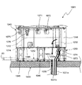
図21は上記貯湯ユニット1001の下部の正面図を示している。図21において、図19,図20と同一の構成部には同一参照番号を付している。 FIG. 21 shows a front view of the lower portion of the hot water storage unit 1001. 21, the same components as those in FIGS. 19 and 20 are designated by the same reference numerals.

図21に示すように、蓋板1048の前方に水配管用接続口1071,1072を設けている。水配管用接続口1071,1072は、ケーシング1040内の水配管1061,1063(図19に示す)を介して、貯湯タンク1011の頂部に接続されている。これにより、水配管用接続口1071,1072に水配管(図示せず)を接続すれば、貯湯タンク1011内の温水を他の給湯端末に流すことができるようになっている。なお、図17では、水配管1061,1063および水配管用接続口1071,1072の図示を省略している。 As shown in FIG. 21, water pipe connection ports 1071 and 1072 are provided in front of the cover plate 1048. The water pipe connection ports 1071 and 1072 are connected to the top of the hot water storage tank 1011 via water pipes 1061 and 1063 (shown in FIG. 19) in the casing 1040. Accordingly, by connecting a water pipe (not shown) to the water pipe connection ports 1071 and 1072, the hot water in the hot water storage tank 1011 can be flowed to another hot water supply terminal. In FIG. 17, the water pipes 1061 and 1063 and the water pipe connection ports 1071 and 1072 are not shown.

上記水配管用接続口1071,1072の一側方に冷媒配管接続部1073,1074を設けている。この冷媒配管接続部1073,1074の高さ方向の位置は、水配管用接続口1071,1072の高さ方向の位置よりも低い。 Refrigerant pipe connection portions 1073 and 1074 are provided on one side of the water pipe connection ports 1071 and 1072. The positions of the refrigerant pipe connection portions 1073 and 1074 in the height direction are lower than the positions of the water pipe connection ports 1071 and 1072 in the height direction.

また、上記水配管用接続口1071,1072の他側方には、水配管用接続口1075,1076が設けられている。 Further, water pipe connection ports 1075 and 1076 are provided on the other side of the water pipe connection ports 1071 and 1072.

上記構成の貯湯ユニット1001は、図21に示すように、床1400上に設置されている。貯湯ユニット1001は、冷媒配管接続部1073に冷媒配管1031の復配管1031bの一端が接続されると共に、冷媒配管接続部1074に冷媒配管1031の往配管1031aの一端を接続している。この冷媒配管1031(往配管1031a,復配管1031b)は、床1400に設けられた穴1400aを介して床1400の下側に配設され、室外に設置されたヒートポンプユニット1002(図17に示す)に接続される。 The hot water storage unit 1001 having the above configuration is installed on the floor 1400, as shown in FIG. In the hot water storage unit 1001, one end of the return pipe 1031b of the refrigerant pipe 1031 is connected to the refrigerant pipe connection portion 1073, and one end of the forward pipe 1031a of the refrigerant pipe 1031 is connected to the refrigerant pipe connection portion 1074. The refrigerant pipe 1031 (outgoing pipe 1031a, return pipe 1031b) is disposed below the floor 1400 through a hole 1400a provided in the floor 1400, and is installed outside the heat pump unit 1002 (shown in FIG. 17). Connected to.

また、ケーシング1040の底板1045に一端が接続された排出ホース1230によって、ケーシング1040内と床下を連通している。上記排出ホース1230は、第1カバー部材の一例である。 Further, the inside of the casing 1040 is communicated with the underfloor by a discharge hose 1230 having one end connected to the bottom plate 1045 of the casing 1040. The discharge hose 1230 is an example of the first cover member.

また、上記構成の貯湯ユニット1001において、ケーシング1040内に配置された断熱材1014(内部カバー部材)により、冷媒回路の冷媒配管接続部分を覆うと共に漏洩した可燃性冷媒をケーシング1040外に案内する。例えば、ケーシング1040内に可燃性冷媒が急速漏洩した場合、漏洩した直後の可燃性冷媒のうちの多くは液体のままであるので、断熱材1014に案内されて、接続口1232を介して排出ホース1230により床下に排出される。 In the hot water storage unit 1001 having the above configuration, the heat insulating material 1014 (internal cover member) arranged in the casing 1040 covers the refrigerant pipe connection portion of the refrigerant circuit and guides the leaked combustible refrigerant to the outside of the casing 1040. For example, when the flammable refrigerant rapidly leaks into the casing 1040, most of the flammable refrigerant immediately after the leakage remains a liquid, and therefore the heat hose 1014 guides the discharge hose through the connection port 1232. Discharged under floor by 1230.

したがって、この貯湯ユニット1001が室内に設置された環境においても、断熱材1014により案内された可燃性冷媒がケーシング1040内から室内へ漏れないように、排出ホース1230により床下に排出する処理が可能になる。このように、可燃性冷媒の漏洩時に室内への冷媒漏れを防ぐことができ、室内に可燃性冷媒が滞留してガス濃度が高くなって発火などのリスクが高まるのを抑制できる。 Therefore, even in an environment where this hot water storage unit 1001 is installed indoors, it is possible to perform a process of discharging the flammable refrigerant guided by the heat insulating material 1014 to the room under the floor with the discharge hose 1230 so that the flammable refrigerant does not leak from the inside of the casing 1040 to the room. Become. In this way, when the flammable refrigerant leaks, it is possible to prevent the refrigerant from leaking into the room, and it is possible to prevent the flammable refrigerant from staying in the room and increasing the gas concentration and increasing the risk of ignition or the like.

また、上記水熱交換器1012を断熱材1014(内部カバー部材)により覆うことによって、水熱交換器1012の冷媒配管接続部分や水熱交換器1012自体から可燃性冷媒が漏洩しても、ケーシング1040内に拡散することなく、ケーシング1040外に排出できる。 Further, by covering the water heat exchanger 1012 with the heat insulating material 1014 (internal cover member), even if the flammable refrigerant leaks from the refrigerant pipe connection portion of the water heat exchanger 1012 or the water heat exchanger 1012 itself, the casing It can be discharged to the outside of the casing 1040 without diffusing into the inside of 1040.

また、上記ケーシング1040内の冷媒回路の全てを断熱材1014により覆うことによって、ケーシング1040内の冷媒回路のどの箇所から可燃性冷媒が漏洩しても、ケーシング1040内に拡散することなく、ケーシング1040外に確実に排出できる。 Further, by covering all of the refrigerant circuit in the casing 1040 with the heat insulating material 1014, even if the flammable refrigerant leaks from any portion of the refrigerant circuit in the casing 1040, the flammable refrigerant does not diffuse into the casing 1040 and the casing 1040 is not diffused. Can be reliably discharged to the outside.

また、内部カバー部材に断熱材1014を用いて、水熱交換器1012を覆うことによって、水熱交換器1012を断熱する断熱材を兼ねることができ、断熱効果を高めることができる。 Further, by using the heat insulating material 1014 for the inner cover member and covering the water heat exchanger 1012, it is possible to serve also as a heat insulating material for insulating the water heat exchanger 1012, and the heat insulating effect can be enhanced.

また、排出部材に排出ホース1230を用いることによって、ケーシング1040内に漏洩した可燃性冷媒を床下に導く経路を容易に設けることができ、可撓性を有するホースを用いることで設置の自由度が高まると共に作業性が向上する。 Further, by using the discharge hose 1230 as the discharge member, it is possible to easily provide a path for guiding the flammable refrigerant leaking into the casing 1040 to the underfloor, and a flexible hose provides flexibility in installation. Workability is improved as it is increased.

また、上記ケーシング1040内に漏洩した可燃性冷媒(特に液冷媒)がケーシング1040内の底部に溜まるので、ケーシング1040の下部と床下とを排出ホース1230(排出部材)により連通することによって、漏洩した可燃性冷媒のうちの多くを占める液冷媒を、ケーシング1040の下部から排出ホース1230を介して床下に速やかに排出することができる。 In addition, since flammable refrigerant (particularly liquid refrigerant) that leaks into the casing 1040 collects at the bottom of the casing 1040, the bottom of the casing 1040 and the underfloor are connected by a discharge hose 1230 (a discharge member), and thus leaked. The liquid refrigerant that occupies most of the combustible refrigerant can be quickly discharged from the lower portion of the casing 1040 to the underfloor via the discharge hose 1230.

また、上記ケーシング1040内の水熱交換器1012の下部に設けられた接続口1232に、排出ホース1230(排出部材)を接続することによって、水熱交換器1012の冷媒配管接続部分から漏れ出た可燃性冷媒は、水熱交換器1012の下側に流れ落ちて、下側の接続口1232を介して排出ホース1230により床下に排出することができる。 Further, by connecting the discharge hose 1230 (discharge member) to the connection port 1232 provided in the lower part of the water heat exchanger 1012 in the casing 1040, the refrigerant leaked from the refrigerant pipe connection portion of the water heat exchanger 1012. The flammable refrigerant flows down to the lower side of the water heat exchanger 1012, and can be discharged under the floor by the discharge hose 1230 via the lower connection port 1232.

〔第9実施形態〕
図22はこの発明の第9実施形態の貯湯ユニット1001の下部の正面図を示している。この第9実施形態の貯湯ユニット1001は、接続口1232がない点と排出ホース1230と化粧パネル1250を除いて第8実施形態の貯湯ユニット1001と同一の構成をしており、図17〜図20を援用する。
[Ninth Embodiment]
FIG. 22 shows a front view of the lower portion of the hot water storage unit 1001 according to the ninth embodiment of the present invention. The hot water storage unit 1001 of the ninth embodiment has the same configuration as the hot water storage unit 1001 of the eighth embodiment except that there is no connection port 1232, the discharge hose 1230, and the decorative panel 1250, and FIGS. Is used.

この第9実施形態の貯湯ユニット1001は、図22に示すように、ケーシング1040の底板1045と床1400との間に、全周を囲うように化粧パネル1250が配置されている。 In hot water storage unit 1001 of the ninth embodiment, as shown in FIG. 22, a decorative panel 1250 is arranged between bottom plate 1045 of casing 1040 and floor 1400 so as to surround the entire circumference.

上記化粧パネル1250は、冷媒配管1031(1031a,1031b)および排出ホース1230の一部を収容する箱状の通路を構成している。この冷媒配管1031(1031a,1031b)は、床1400に設けられた穴1400aを介して床1400の下側に配設され、ヒートポンプユニット1002(図8に示す)に接続される。 The decorative panel 1250 constitutes a box-shaped passage that accommodates a part of the refrigerant pipe 1031 (1031a, 1031b) and the discharge hose 1230. The refrigerant pipe 1031 (1031a, 1031b) is arranged below the floor 1400 via a hole 1400a provided in the floor 1400, and is connected to the heat pump unit 1002 (shown in FIG. 8).

上記排出ホース1230と化粧パネル1250で排出部材を構成している。 The discharge hose 1230 and the decorative panel 1250 constitute a discharge member.

また、化粧パネル1250内の下側に液体受け部材1252を配置している。この液体受け部材1252の最も低い位置に設けられた接続口1252aに排出ホース1230の上端を接続することによって、化粧パネル1250と排出ホース1230を介して貯湯ユニット1001のケーシング1040内部と床下とを連通している。 Further, the liquid receiving member 1252 is arranged on the lower side in the decorative panel 1250. By connecting the upper end of the discharge hose 1230 to the connection port 1252a provided at the lowest position of the liquid receiving member 1252, the interior of the casing 1040 of the hot water storage unit 1001 and the underfloor are communicated with each other via the decorative panel 1250 and the discharge hose 1230. doing.

上記液体受け部材1252の底面の傾斜角度θ3[deg]を所定角度θ3min[deg]よりも大きい値に設定している。この所定角度θ3min[deg]は、貯湯ユニット1001から可燃性冷媒が急速漏洩したときの冷媒量やケーシング1040および化粧パネル1250の構成などに応じて適宜決定される。 The inclination angle θ3 [deg] of the bottom surface of the liquid receiving member 1252 is set to a value larger than the predetermined angle θ3 min [deg]. The predetermined angle θ3 min [deg] is appropriately determined according to the amount of the refrigerant when the combustible refrigerant rapidly leaks from the hot water storage unit 1001, the configuration of the casing 1040 and the decorative panel 1250, and the like.

上記第9実施形態では、化粧パネル1250内の下側に液体受け部材1252を配置したが、液体受け部材または排出ホースの少なくとも一方を備えない構成でもよい。この場合でも、箱状の通路を構成する置台によりケーシング内から漏洩した可燃性冷媒を床下に案内することができる。 In the ninth embodiment, the liquid receiving member 1252 is arranged on the lower side in the decorative panel 1250, but the configuration may be such that at least one of the liquid receiving member and the discharge hose is not provided. Even in this case, the flammable refrigerant leaked from the inside of the casing can be guided to the underfloor by the mounting table forming the box-shaped passage.

上記第9実施形態の貯湯ユニット1001は、第8実施形態の貯湯ユニット1001と同様の効果を有する。 The hot water storage unit 1001 of the ninth embodiment has the same effects as the hot water storage unit 1001 of the eighth embodiment.

また、壁面に設置するタイプの貯湯ユニット1001において、ケーシング1040下部に箱状の通路として化粧パネル1250を用いることによって、壁面に設置したケーシング1040の下側空間(配管などが敷設される空間)を化粧パネル1250で覆って、美観を損ねることなく、ケーシング1040内に漏洩した可燃性冷媒を床下に導く通路を形成できる。 Further, in the hot water storage unit 1001 of the type installed on the wall surface, by using the decorative panel 1250 as a box-shaped passage below the casing 1040, the lower space of the casing 1040 installed on the wall surface (a space where pipes and the like are laid) is provided. By covering with the decorative panel 1250, a passage for guiding the flammable refrigerant leaking into the casing 1040 to the underfloor can be formed without impairing the appearance.

また、上記化粧パネル1250内に配置された液体受け部材1252により、漏洩した可燃性冷媒(または冷水供給時の結露水などの液体)を、排出ホース1230(排出部材)が接続された接続口1252aに確実に案内することができる。 In addition, the liquid receiving member 1252 arranged in the decorative panel 1250 allows the leaked combustible refrigerant (or liquid such as dew condensation water when cold water is supplied) to be connected to a discharge port 1252a to which a discharge hose 1230 (discharge member) is connected. Can be surely guided.

また、上記液体受け部材1252の傾斜した底面によって、ケーシング1040下部から漏洩した可燃性冷媒(または冷水供給時の結露水などの液体)を、排出ホース1230が接続された接続口1252aにスムーズに案内することができる。 Further, the inclined bottom surface of the liquid receiving member 1252 smoothly guides the flammable refrigerant (or liquid such as dew condensation water when cold water is supplied) leaked from the lower portion of the casing 1040 to the connection port 1252a to which the discharge hose 1230 is connected. can do.

また、上記ケーシング1040外において、冷媒配管1031(1031a,1031b)が接続された冷媒配管接続部1074,1073から可燃性冷媒が漏れ出ても、化粧パネル1250内で受けて排出ホース1230により床下に排出することができ、より安全性が高まる。 Further, outside the casing 1040, even if the flammable refrigerant leaks out from the refrigerant pipe connecting portions 1074 and 1073 to which the refrigerant pipe 1031 (1031a, 1031b) is connected, it is received in the decorative panel 1250 and discharged under the floor by the discharge hose 1230. It can be discharged, making it more safe.

〔第10実施形態〕
図23はこの発明の第10実施形態の貯湯ユニット1001の下部の正面図を示している。この第10実施形態の貯湯ユニット1001は、排出ホース1230と第1カバー部材1270を除いて第8実施形態の貯湯ユニット1001と同一の構成をしており、図17〜図20を援用する。
[Tenth Embodiment]
FIG. 23 is a front view of the lower portion of the hot water storage unit 1001 according to the tenth embodiment of the present invention. The hot water storage unit 1001 of the tenth embodiment has the same configuration as the hot water storage unit 1001 of the eighth embodiment except for the discharge hose 1230 and the first cover member 1270, and FIGS. 17 to 20 are cited.

この第10実施形態の貯湯ユニット1001は、図23に示すように、蓋板1048に冷媒配管1031(往配管1031a,復配管1031b)を覆う第1カバー部材1270を取り付けている。この第1カバー部材1270は、冷媒配管接続部1074に接続された冷媒配管1031の往配管1031aおよび冷媒配管接続部1073に接続された冷媒配管1031の復配管1031bが貫通する穴(図示せず)を有する。また、第1カバー部材1270は、排出ホース1230の上端が接続された接続穴(図示せず)を有する。また、ケーシング1040内の水熱交換器1012の下部に設けられた接続口1232を介して、ケーシング1040内と第1カバー部材1270内とが連通している。 In the hot water storage unit 1001 of the tenth embodiment, as shown in FIG. 23, a first cover member 1270 that covers the refrigerant pipe 1031 (the forward pipe 1031a, the return pipe 1031b) is attached to the lid plate 1048. The first cover member 1270 has a hole (not shown) through which the forward pipe 1031a of the refrigerant pipe 1031 connected to the refrigerant pipe connecting portion 1074 and the return pipe 1031b of the refrigerant pipe 1031 connected to the refrigerant pipe connecting portion 1073 pass. Have. In addition, the first cover member 1270 has a connection hole (not shown) to which the upper end of the discharge hose 1230 is connected. Further, the inside of the casing 1040 and the inside of the first cover member 1270 are in communication with each other via the connection port 1232 provided in the lower portion of the water heat exchanger 1012 inside the casing 1040.

上記排出ホース1230と第1カバー部材1270で排出部材を構成している。 The discharge hose 1230 and the first cover member 1270 form a discharge member.

また、上記構成の貯湯ユニット1001において、ケーシング1040内に配置された断熱材1014(内部カバー部材)により、冷媒回路の冷媒配管接続部分を覆うと共に漏洩した可燃性冷媒をケーシング1040外に案内する。例えば、ケーシング1040内に可燃性冷媒が急速漏洩した場合、漏洩した直後の可燃性冷媒のうちの多くは液体のままであるので、断熱材1014に案内されて、接続口1232から第1カバー部材1270と排出ホース1230を介して流れ落ちて床下に速やかに排出することが可能になる。 In the hot water storage unit 1001 having the above configuration, the heat insulating material 1014 (internal cover member) arranged in the casing 1040 covers the refrigerant pipe connection portion of the refrigerant circuit and guides the leaked combustible refrigerant to the outside of the casing 1040. For example, when the flammable refrigerant rapidly leaks into the casing 1040, most of the flammable refrigerant immediately after the leakage remains a liquid, and thus is guided by the heat insulating material 1014 to be guided from the connection port 1232 to the first cover member. It becomes possible to flow down through the 1270 and the discharge hose 1230 and quickly discharge it under the floor.

したがって、この貯湯ユニット1001が室内に設置された環境においても、断熱材1014により案内された可燃性冷媒がケーシング1040内から室内へ漏れないように、第1カバー部材1270と排出ホース1230により床下に排出する処理が可能になる。このように、可燃性冷媒の漏洩時に室内への冷媒漏れを防ぐことができ、室内に可燃性冷媒が滞留してガス濃度が高くなって発火などのリスクが高まるのを抑制できる。 Therefore, even in an environment where this hot water storage unit 1001 is installed indoors, the first cover member 1270 and the discharge hose 1230 are provided under the floor so that the flammable refrigerant guided by the heat insulating material 1014 does not leak into the room from the casing 1040. It becomes possible to process to discharge. In this way, when the flammable refrigerant leaks, it is possible to prevent the refrigerant from leaking into the room, and it is possible to prevent the flammable refrigerant from staying in the room and increasing the gas concentration and increasing the risk of ignition or the like.

なお、気化した上記可燃性冷媒が空気よりも重い場合、気体の可燃性冷媒も下方に流れてケーシング1040内から第1カバー部材1270と排出ホース1230を介して下方に排出される。 When the vaporized flammable refrigerant is heavier than air, the gaseous flammable refrigerant also flows downward and is discharged downward from the inside of the casing 1040 via the first cover member 1270 and the discharge hose 1230.

また、上記ケーシング1040内に漏洩した可燃性冷媒(特に液冷媒)がケーシング1040内の底部に溜まるので、ケーシング1040の下部からの漏洩冷媒を第1カバー部材1270により排出することで、ケーシング1040内に漏洩した可燃性冷媒のうちの多くを占める液冷媒を、ケーシング1040の下部から第1カバー部材1270と排出ホース1230を介して床下に速やかに排出することができる。 In addition, since flammable refrigerant (particularly liquid refrigerant) that leaks into the casing 1040 collects at the bottom of the casing 1040, the leakage of refrigerant from the lower portion of the casing 1040 is discharged by the first cover member 1270. The liquid refrigerant that occupies most of the flammable refrigerant that has leaked to the bottom can be quickly discharged from the lower portion of the casing 1040 under the floor via the first cover member 1270 and the discharge hose 1230.

また、上記第1カバー部材1270がケーシング1040外の冷媒配管接続部1234,1235を覆っていることによって、そのケーシング1040外の冷媒配管接続部1234,1235から可燃性冷媒が漏れ出ても第1カバー部材1270内で受けて排出することができ、より安全性が高まる。 Further, since the first cover member 1270 covers the refrigerant pipe connecting portions 1234 and 1235 outside the casing 1040, even if the flammable refrigerant leaks from the refrigerant pipe connecting portions 1234 and 1235 outside the casing 1040, Since it can be received and discharged in the cover member 1270, the safety is further enhanced.

また、上記水熱交換器1012が収容されたケーシング1040内と床下を第1カバー部材1270,排出ホース1230(排出部材)により連通することによって、室内に設置された状態でケーシング1040内に可燃性冷媒が急速漏洩した場合、ケーシング1040内に漏洩した直後の可燃性冷媒のうちの多くは蒸発しきらずに液体のままケーシング1040内から排出ホース1230を介して流れ落ちて床下に速やかに排出される。 Further, the inside of the casing 1040 accommodating the water heat exchanger 1012 is communicated with the underfloor by the first cover member 1270 and the discharge hose 1230 (discharge member), so that the casing 1040 is flammable in the state where it is installed indoors. When the refrigerant rapidly leaks, most of the flammable refrigerant immediately after leaking into the casing 1040 does not evaporate and remains as a liquid from the inside of the casing 1040 through the discharge hose 1230 and is quickly discharged under the floor.

また、排出部材に排出ホース1230を用いることによって、ケーシング1040内に漏洩した可燃性冷媒を床下に導く経路を容易に設けることができ、可撓性を有するホースを用いることで設置の自由度が高まると共に作業性が向上する。 Further, by using the discharge hose 1230 as the discharge member, it is possible to easily provide a path for guiding the flammable refrigerant leaking into the casing 1040 to the underfloor, and a flexible hose provides flexibility in installation. Workability is improved as it is increased.

上記第10実施形態の貯湯ユニット1001は、第8実施形態の貯湯ユニット1001と同様の効果を有する。 The hot water storage unit 1001 of the tenth embodiment has the same effects as the hot water storage unit 1001 of the eighth embodiment.

〔第11実施形態〕
図24はこの発明の第11実施形態の貯湯ユニット1001の下部の正面図を示している。この第10実施形態の貯湯ユニット1001は、第1カバー部材1275を除いて第10実施形態の貯湯ユニット1001と同一の構成をしており、図17〜図20を援用する。
[Eleventh Embodiment]
FIG. 24 shows a front view of the lower portion of the hot water storage unit 1001 according to the eleventh embodiment of the present invention. The hot water storage unit 1001 of the tenth embodiment has the same configuration as the hot water storage unit 1001 of the tenth embodiment except for the first cover member 1275, and FIGS. 17 to 20 are cited.

この第11実施形態の貯湯ユニット1001は、図24に示すように、蓋板1048に冷媒配管1031(往配管1031a,復配管1031b)を覆う第1カバー部材1275を取り付けている。この第1カバー部材1275の本体部1275aは、冷媒配管接続部1074に接続された冷媒配管1031の往配管1031aおよび冷媒配管接続部1073に接続された冷媒配管1031の復配管1031bが貫通する穴(図示せず)を有する。また、第1カバー部材1275の本体部1275aは、排出ホース1230の上端が接続された接続穴(図示せず)を有する。 In the hot water storage unit 1001 of the eleventh embodiment, as shown in FIG. 24, a first cover member 1275 that covers the refrigerant pipe 1031 (the forward pipe 1031a, the return pipe 1031b) is attached to the lid plate 1048. The body portion 1275a of the first cover member 1275 has a hole through which the return pipe 1031a of the refrigerant pipe 1031 connected to the refrigerant pipe connection portion 1074 and the return pipe 1031b of the refrigerant pipe 1031 connected to the refrigerant pipe connection portion 1073 pass ( (Not shown). Further, the main body portion 1275a of the first cover member 1275 has a connection hole (not shown) to which the upper end of the discharge hose 1230 is connected.

さらに、第1カバー部材1275は、本体部1275aの右側からケーシング1040の右側面に沿って上方に延びる案内通路1275bを有する。 Further, the first cover member 1275 has a guide passage 1275b extending upward from the right side of the main body 1275a along the right side surface of the casing 1040.

上記排出ホース1230と第1カバー部材1275で排出部材を構成している。 The discharge hose 1230 and the first cover member 1275 form a discharge member.

また、上記構成の貯湯ユニット1001において、ケーシング1040内に配置された断熱材1014(内部カバー部材)により、冷媒回路の冷媒配管接続部分を覆うと共に漏洩した可燃性冷媒をケーシング1040外に案内する。例えば、ケーシング1040内に可燃性冷媒が急速漏洩した場合、漏洩した直後の可燃性冷媒のうちの多くは液体のままであるので、断熱材1014に案内されて、ケーシング1040の右側面に設けた接続口1232から第1カバー部材1275と排出ホース1230を介して、第1カバー部材1275の案内通路1275bに流れ出て本体部1275aに導かれ、排出ホース1230を介して床1400の下側に速やかに排出することが可能になる。 In the hot water storage unit 1001 having the above configuration, the heat insulating material 1014 (internal cover member) arranged in the casing 1040 covers the refrigerant pipe connection portion of the refrigerant circuit and guides the leaked combustible refrigerant to the outside of the casing 1040. For example, when the flammable refrigerant rapidly leaks into the casing 1040, most of the flammable refrigerant immediately after the leakage remains a liquid, so that the flammable refrigerant is guided by the heat insulating material 1014 and provided on the right side surface of the casing 1040. From the connection port 1232 through the first cover member 1275 and the discharge hose 1230, it flows out into the guide passage 1275b of the first cover member 1275, is guided to the main body portion 1275a, and quickly to the lower side of the floor 1400 via the discharge hose 1230. It becomes possible to discharge.

このように第1カバー部材1275は、第7実施形態の図16に示す冷温水供給ユニット200における第1カバー部材275と同様の効果を有する。 In this way, the first cover member 1275 has the same effect as the first cover member 275 in the cold/hot water supply unit 200 shown in FIG. 16 of the seventh embodiment.

したがって、この貯湯ユニット1001が室内に設置された環境においても、断熱材1014により案内された可燃性冷媒がケーシング1040内から室内へ漏れないように、第1カバー部材1275と排出ホース1230により床下に排出する処理が可能になる。このように、可燃性冷媒の漏洩時に室内への冷媒漏れを防ぐことができ、室内に可燃性冷媒が滞留してガス濃度が高くなって発火などのリスクが高まるのを抑制できる。 Therefore, even in an environment where this hot water storage unit 1001 is installed indoors, the first cover member 1275 and the discharge hose 1230 are provided under the floor so that the flammable refrigerant guided by the heat insulating material 1014 does not leak into the room from the casing 1040. It becomes possible to process to discharge. In this way, when the flammable refrigerant leaks, it is possible to prevent the refrigerant from leaking into the room, and it is possible to prevent the flammable refrigerant from staying in the room and increasing the gas concentration and increasing the risk of ignition or the like.

上記可燃性冷媒として、微燃性のR32からなる単一冷媒またはR32を主成分とする混合冷媒を用いることによって、R32はオゾン破壊係数や地球温暖化係数GWPが低いので、地球温暖化への影響を抑えることができると共に、成績係数COP(Coefficient Of Performance)が向上してエネルギー消費を低減することができる。 By using a single refrigerant composed of slightly flammable R32 or a mixed refrigerant containing R32 as a main component as the flammable refrigerant, R32 has a low ozone depletion potential and a global warming potential GWP. It is possible to suppress the influence and improve the coefficient of performance COP (Coefficient Of Performance) to reduce energy consumption.

上記第1〜第11実施形態では、可燃性冷媒として、微燃性のR32の単一冷媒またはR32を主成分とする混合冷媒を用いたが、これに限らず、他の可燃性冷媒を用いた水熱交換器収容ユニットにこの発明を適用してもよい。 In the first to eleventh embodiments, the slightly flammable R32 single refrigerant or the mixed refrigerant containing R32 as a main component is used as the flammable refrigerant, but the invention is not limited to this, and another flammable refrigerant is used. The present invention may be applied to a conventional water heat exchanger housing unit.

また、上記第1〜第11実施形態では、水熱交換器収容ユニットとして冷温水供給ユニット200および貯湯ユニット1001について説明したが、水熱交換器収容ユニットはこれに限らず、可燃性冷媒が流れる水熱交換器と、その水熱交換器が収容されたケーシングを備えた装置にこの発明を適用することができる。 Moreover, in the said 1st-11th embodiment, although the cold/hot water supply unit 200 and the hot water storage unit 1001 were demonstrated as a water heat exchanger accommodation unit, a water heat exchanger accommodation unit is not restricted to this, but a flammable refrigerant flows. The present invention can be applied to a device including a water heat exchanger and a casing that houses the water heat exchanger.

この発明の具体的な実施の形態について説明したが、この発明は上記第1〜第11実施形態に限定されるものではなく、この発明の範囲内で種々変更して実施することができる。例えば、上記第1〜第11実施形態で記載した内容を適宜組み合わせたものを、この発明の一実施形態としてもよい。 Although specific embodiments of the present invention have been described, the present invention is not limited to the above-described first to eleventh embodiments, and various modifications can be implemented within the scope of the present invention. For example, an appropriate combination of the contents described in the first to eleventh embodiments may be an embodiment of the present invention.

100…室外機
101…圧縮機
102…四路切換弁
103…室外熱交換器
104…電動膨張弁
105…アキュムレータ
120…室外機用制御装置
200…冷温水供給ユニット
201,1012…水熱交換器
202…膨張タンク
203,1034…循環ポンプ
204…往きヘッダ
205…戻りヘッダ
215…圧力センサ
216…受液器
220…冷温水供給ユニット用制御装置
221…基板カバー部材
230,1230…排出ホース
231,1040…ケーシング
232,260a,241,276,1232,1233…接続口
234,235,1073,1074…冷媒配管接続部
250…置台
251,252,260…液体受け部材
270,275,1270,1275…第1カバー部材
280…第2カバー部材
280a…本体部
280b…案内部
290…背面断熱部材
295…前面断熱部材
301〜304…第1〜第4水循環パイプ
400…床
400a…穴
1001…貯湯ユニット
1002…ヒートポンプユニット
1011…貯湯タンク
1012…水熱交換器
1014…断熱材
1021…圧縮機
1022…膨張手段
1023…空気熱交換器
1031…冷媒配管
1031a…往配管
1031b…復配管
1036…混合弁
E…給水源
L1,L2…冷媒配管
P1〜P4…第1〜第4床冷暖房パネル
T…給湯端末
V1〜V4…第1〜第4熱動弁
100...Outdoor unit 101...Compressor 102...Four-way switching valve 103...Outdoor heat exchanger 104...Electric expansion valve 105...Accumulator 120...Outdoor unit control device 200...Cold/hot water supply unit 201,1012...Water heat exchanger 202 ...Expansion tank 203, 1034... Circulation pump 204... Outgoing header 205... Return header 215... Pressure sensor 216... Liquid receiver 220... Cold/hot water supply unit control device 221... Board cover member 230, 1230... Discharge hose 231, 1040... Casing 232, 260a, 241, 276, 1232, 1233... Connection port 234, 235, 1073, 1074... Refrigerant pipe connection part 250... Mounting stand 251, 252, 260... Liquid receiving member 270, 275, 1270, 1275... First cover Member 280... 2nd cover member 280a... Main part 280b... Guide part 290... Rear heat insulation member 295... Front heat insulation member 301-304... 1st-4th water circulation pipe 400... Floor 400a... Hole 1001... Hot water storage unit 1002... Heat pump unit 1011... Hot water storage tank 1012... Water heat exchanger 1014... Insulation material 1021... Compressor 1022... Expansion means 1023... Air heat exchanger 1031... Refrigerant piping 1031a... Outgoing piping 1031b... Return piping 1036... Mixing valve E... Water supply source L1, L2... Refrigerant piping P1 to P4... First to fourth floor cooling/heating panel T... Hot water supply terminal V1 to V4... First to fourth thermal valve

Claims (5)

可燃性冷媒が流れる水熱交換器(201)と、
上記水熱交換器(201)が収容されたケーシング(231)と、
上記ケーシング(231)内に配置され、少なくとも冷媒回路の冷媒配管接続部分を覆うと共に漏洩した可燃性冷媒を上記ケーシング(231)外に案内する内部カバー部材(280)と
を備え、
上記内部カバー部材(280)は、上記ケーシング(231)に設けられた接続口(241)に係合し、かつ、上記接続口(241)に上記漏洩した可燃性冷媒を案内する案内部(280b)を有することを特徴とする水熱交換器収容ユニット。
A water heat exchanger (201) through which a flammable refrigerant flows,
A casing (231) accommodating the water heat exchanger (201),
An inner cover member (280) disposed in the casing (231), which covers at least the refrigerant pipe connection portion of the refrigerant circuit and guides the leaked combustible refrigerant to the outside of the casing (231),
The inner cover member (280) engages with the connection port (241) provided in the casing (231) and guides the leaked combustible refrigerant to the connection port (241) (280b). ). A water heat exchanger housing unit.
請求項1に記載の水熱交換器収容ユニットにおいて、
上記内部カバー部材(280)は、上記水熱交換器(201)を覆っていることを特徴とする水熱交換器収容ユニット。
The water heat exchanger housing unit according to claim 1 ,
The water heat exchanger housing unit, wherein the inner cover member (280 ) covers the water heat exchanger (201 ) .
請求項1に記載の水熱交換器収容ユニットにおいて、
上記内部カバー部材(280)は、上記ケーシング(231)内の冷媒回路の全てを覆っていることを特徴とする水熱交換器収容ユニット。
The water heat exchanger housing unit according to claim 1 ,
The water heat exchanger housing unit, wherein the inner cover member (280 ) covers the entire refrigerant circuit in the casing (231 ) .
請求項1から3までのいずれか1つに記載の水熱交換器収容ユニットにおいて、
上記内部カバー部材(280)は、断熱材からなることを特徴とする水熱交換器収容ユニット。
The water heat exchanger housing unit according to any one of claims 1 to 3,
The water heat exchanger accommodation unit, wherein the inner cover member (280 ) is made of a heat insulating material.
請求項1からまでのいずれか1つに記載の水熱交換器収容ユニットにおいて、
上記ケーシング(231)内に配置された制御基板(220)と、
上記制御基板(220)を覆う基板カバー部材(221)と
を備えたことを特徴とする水熱交換器収容ユニット。
The water heat exchanger housing unit according to any one of claims 1 to 4 ,
A control board (220) arranged in the casing (231),
A water heat exchanger accommodating unit comprising a substrate cover member (221) covering the control substrate (220).
JP2015193542A 2015-09-30 2015-09-30 Water heat exchanger housing unit Active JP6733145B2 (en)

Priority Applications (4)

Application Number Priority Date Filing Date Title
JP2015193542A JP6733145B2 (en) 2015-09-30 2015-09-30 Water heat exchanger housing unit
PCT/JP2016/077172 WO2017057004A1 (en) 2015-09-30 2016-09-14 Water heat exchanger accommodation unit
EP16851178.0A EP3358272B1 (en) 2015-09-30 2016-09-14 Water heat exchanger accommodation unit
CN201680056004.9A CN108139112B (en) 2015-09-30 2016-09-14 Water heat exchanger accommodating unit

Applications Claiming Priority (1)

Application Number Priority Date Filing Date Title
JP2015193542A JP6733145B2 (en) 2015-09-30 2015-09-30 Water heat exchanger housing unit

Publications (2)

Publication Number Publication Date
JP2017067373A JP2017067373A (en) 2017-04-06
JP6733145B2 true JP6733145B2 (en) 2020-07-29

Family

ID=58423540

Family Applications (1)

Application Number Title Priority Date Filing Date
JP2015193542A Active JP6733145B2 (en) 2015-09-30 2015-09-30 Water heat exchanger housing unit

Country Status (4)

Country Link
EP (1) EP3358272B1 (en)
JP (1) JP6733145B2 (en)
CN (1) CN108139112B (en)
WO (1) WO2017057004A1 (en)

Families Citing this family (18)

* Cited by examiner, † Cited by third party
Publication number Priority date Publication date Assignee Title
AU2018390660B2 (en) 2017-12-18 2023-01-05 Daikin Industries, Ltd. Refrigeration Cycle Apparatus
US11435118B2 (en) 2017-12-18 2022-09-06 Daikin Industries, Ltd. Heat source unit and refrigeration cycle apparatus
US11493244B2 (en) 2017-12-18 2022-11-08 Daikin Industries, Ltd. Air-conditioning unit
US11549695B2 (en) 2017-12-18 2023-01-10 Daikin Industries, Ltd. Heat exchange unit
US11506425B2 (en) 2017-12-18 2022-11-22 Daikin Industries, Ltd. Refrigeration cycle apparatus
US11906207B2 (en) 2017-12-18 2024-02-20 Daikin Industries, Ltd. Refrigeration apparatus
US11441819B2 (en) 2017-12-18 2022-09-13 Daikin Industries, Ltd. Refrigeration cycle apparatus
US11441802B2 (en) 2017-12-18 2022-09-13 Daikin Industries, Ltd. Air conditioning apparatus
US11820933B2 (en) 2017-12-18 2023-11-21 Daikin Industries, Ltd. Refrigeration cycle apparatus
US11365335B2 (en) 2017-12-18 2022-06-21 Daikin Industries, Ltd. Composition comprising refrigerant, use thereof, refrigerating machine having same, and method for operating said refrigerating machine
CN113637457A (en) 2017-12-18 2021-11-12 大金工业株式会社 Composition containing refrigerant, use thereof, refrigerator having same, and method for operating refrigerator
US11549041B2 (en) 2017-12-18 2023-01-10 Daikin Industries, Ltd. Composition containing refrigerant, use of said composition, refrigerator having said composition, and method for operating said refrigerator
WO2019123897A1 (en) * 2017-12-18 2019-06-27 ダイキン工業株式会社 Refrigeration cycle device
EP4130600A4 (en) * 2020-03-23 2023-12-13 Toshiba Carrier Corporation Hot water generating device
CN115398163B (en) * 2020-04-20 2023-11-10 三菱电机株式会社 Relay and air conditioner provided with same
KR102638189B1 (en) * 2021-07-26 2024-02-16 엘지전자 주식회사 Heat supply apparatus
EP4177546A1 (en) * 2021-11-08 2023-05-10 Ariston S.P.A. Housing chamber for the refrigerant circuit of a heat pump, equipped with anti-surge means
DE102022123440A1 (en) 2022-09-14 2024-03-14 Vaillant Gmbh Service connection for a heat pump housing

Family Cites Families (13)

* Cited by examiner, † Cited by third party
Publication number Priority date Publication date Assignee Title
IT1275221B (en) * 1995-02-07 1997-07-31 Miralfin Srl EQUIPMENT AND PROCEDURE FOR AIR CONDITIONING WITH A REFRIGERANT FLUID THAT IS NOT HARMFUL AT LEAST TO STRATOSPHERIC OZONE
JPH1047751A (en) * 1996-08-02 1998-02-20 Daikin Ind Ltd Air conditioner using combustible refrigerant
JP2001099530A (en) * 1999-09-30 2001-04-13 Hitachi Ltd Air conditioner
JP2004286315A (en) * 2003-03-24 2004-10-14 Japanese Research & Development Association For Environment-Friendly Processing In Food Industry Safety device of refrigerating circuit
JP2008292066A (en) * 2007-05-25 2008-12-04 Hitachi Appliances Inc Air conditioner
EP2110614B1 (en) * 2008-04-16 2014-10-01 Truma Gerätetechnik GmbH & Co. KG Air conditioning device with safety device avoiding refrigerant leak into inside of room
DE102009029392A1 (en) * 2009-09-11 2011-03-24 WESKA Kälteanlagen GmbH Explosion-proof refrigeration system with flammable refrigerant
JP5726009B2 (en) * 2011-07-28 2015-05-27 ホシザキ電機株式会社 Ice machine
JP5834625B2 (en) * 2011-08-26 2015-12-24 株式会社ノーリツ Heat pump water heater
JP5838660B2 (en) * 2011-08-29 2016-01-06 株式会社ノーリツ Heat pump water heater
JP6051615B2 (en) * 2012-06-26 2016-12-27 株式会社ノーリツ Heat pump heat source machine
WO2015029094A1 (en) * 2013-08-25 2015-03-05 Masuda Keiji Leak detecting structure for flammable refrigerant
JP6128331B2 (en) * 2014-02-26 2017-05-17 株式会社富士通ゼネラル Hot water heater

Also Published As

Publication number Publication date
EP3358272A4 (en) 2019-06-12
WO2017057004A1 (en) 2017-04-06
EP3358272A1 (en) 2018-08-08
JP2017067373A (en) 2017-04-06
EP3358272B1 (en) 2020-06-17
CN108139112B (en) 2020-09-04
CN108139112A (en) 2018-06-08

Similar Documents

Publication Publication Date Title
JP6733145B2 (en) Water heat exchanger housing unit
JP6623649B2 (en) Water heat exchanger storage unit
WO2018061548A1 (en) Refrigeration device
JP2018054249A (en) Refrigeration device
JP6720492B2 (en) Water heat exchanger housing unit
CN109154458A (en) Refrigerant flow path switch unit and air conditioner
JP2006234350A (en) Heat pump water heater
JP5012445B2 (en) Outdoor unit of temperature controller
JP2008145003A (en) Heat pump unit
JP6011669B1 (en) Outdoor unit
JP5958241B2 (en) Heat pump heat source machine
JP2008145001A (en) Heat pump unit
JP4899510B2 (en) Heat pump type water heater
JP6051615B2 (en) Heat pump heat source machine
WO2017204063A1 (en) Outdoor unit of heat pump water heater
JP6471059B2 (en) Tank unit
JP2020128833A (en) Heat pump system
JP2012177545A (en) Heat pump unit
JP6398372B2 (en) Air conditioner floor-mounted indoor unit
WO2021161522A1 (en) Heat pump device and hot water storage type hot water supplier
WO2023112430A1 (en) Refrigeration cycle device
JP2017150710A (en) Hot water storage tank unit
EP3907440A1 (en) Warm water unit and heat pump system having the same
KR20110055775A (en) Indoor unit of water circulation system associated with refrigerant cycle
JP2014077636A (en) Heat pump unit

Legal Events

Date Code Title Description
A621 Written request for application examination

Free format text: JAPANESE INTERMEDIATE CODE: A621

Effective date: 20180927

A131 Notification of reasons for refusal

Free format text: JAPANESE INTERMEDIATE CODE: A131

Effective date: 20190702

A521 Request for written amendment filed

Free format text: JAPANESE INTERMEDIATE CODE: A523

Effective date: 20190828

A131 Notification of reasons for refusal

Free format text: JAPANESE INTERMEDIATE CODE: A131

Effective date: 20200204

A521 Request for written amendment filed

Free format text: JAPANESE INTERMEDIATE CODE: A523

Effective date: 20200326

TRDD Decision of grant or rejection written
A01 Written decision to grant a patent or to grant a registration (utility model)

Free format text: JAPANESE INTERMEDIATE CODE: A01

Effective date: 20200609

A61 First payment of annual fees (during grant procedure)

Free format text: JAPANESE INTERMEDIATE CODE: A61

Effective date: 20200622

R151 Written notification of patent or utility model registration

Ref document number: 6733145

Country of ref document: JP

Free format text: JAPANESE INTERMEDIATE CODE: R151