EP3729999B1 - Eckschrank mit einem inneren tablar und einer mitnehmervorrichtung für die tür - Google Patents
Eckschrank mit einem inneren tablar und einer mitnehmervorrichtung für die tür Download PDFInfo
- Publication number
- EP3729999B1 EP3729999B1 EP20159865.3A EP20159865A EP3729999B1 EP 3729999 B1 EP3729999 B1 EP 3729999B1 EP 20159865 A EP20159865 A EP 20159865A EP 3729999 B1 EP3729999 B1 EP 3729999B1
- Authority
- EP
- European Patent Office
- Prior art keywords
- shelf
- corner cabinet
- driver
- door
- links
- Prior art date
- Legal status (The legal status is an assumption and is not a legal conclusion. Google has not performed a legal analysis and makes no representation as to the accuracy of the status listed.)
- Active
Links
Images

Classifications
-
- A—HUMAN NECESSITIES
- A47—FURNITURE; DOMESTIC ARTICLES OR APPLIANCES; COFFEE MILLS; SPICE MILLS; SUCTION CLEANERS IN GENERAL
- A47B—TABLES; DESKS; OFFICE FURNITURE; CABINETS; DRAWERS; GENERAL DETAILS OF FURNITURE
- A47B96/00—Details of cabinets, racks or shelf units not covered by a single one of groups A47B43/00 - A47B95/00; General details of furniture
- A47B96/16—Drawers or movable shelves coupled to doors
-
- A—HUMAN NECESSITIES
- A47—FURNITURE; DOMESTIC ARTICLES OR APPLIANCES; COFFEE MILLS; SPICE MILLS; SUCTION CLEANERS IN GENERAL
- A47B—TABLES; DESKS; OFFICE FURNITURE; CABINETS; DRAWERS; GENERAL DETAILS OF FURNITURE
- A47B81/00—Cabinets or racks specially adapted for other particular purposes, e.g. for storing guns or skis
- A47B81/002—Corner cabinets; Cabinets designed for being placed in a corner or a niche
Definitions
- the invention relates to a corner cupboard, in particular a kitchen corner cupboard, with an interior space which is accessible from the front via a corner cupboard door and is essentially rectangular in plan, with a fitting which is provided with a support which can be supported in a fixed position in the interior of the corner cupboard for holding at least one one-piece shelf of semicircular basic shape, wherein the support has at least one link which supports the shelf and transfers the shelf on a predetermined movement path from an inner position in the interior of the corner cupboard to an outer position located essentially in front of the door opening of the corner cupboard, which is pivotally connected to the shelf and pivotally connected to a corner cupboard part, in particular a side wall of the corner cupboard, wherein a driver device for coupling the door to the shelf during at least part of the opening movement and at least part of the closing movement of the door is provided between the corner cupboard door closing the door opening and the shelf, according to the preamble of patent claim 1.
- a corner cupboard is provided with a coupling means with a bolt and a guide piece as a driver device for coupling the door.
- a bolt and a guide piece are provided on the shelf, whereby the bolt engages the guide piece up to an intermediate position of the shelf for transmitting a corner cupboard door movement to the shelf. If the door a certain opening position is reached, the operator can swing the shelf out of the corner cupboard. To close the door, re-coupling is necessary, which cannot be done automatically. Instead, the operator must carry out this re-coupling process, which is time-consuming in practice.
- the driver device On this corner cupboard and the fitting provided for this corner cupboard, the driver device is equipped with a driver attached to the corner cupboard door, which is provided with a pivoting driver latch that is loaded by a spring, wherein the driver latch can be held in a coupling position with a coupling element of the shelf during an opening movement of the corner cupboard door and can be uncoupled from the driver latch from the coupling element of the shelf during a further opening movement of the shelf after at least one partial opening position of the corner cupboard door.
- the door After the shelf has been moved to an intermediate pivot position or after the shelf has been moved to the closed position, the door must be coupled to the coupling link again. In practice, this coupling process is not very convenient to use. In addition, in practice it is difficult for the door to still be movable in the end position.
- TW 201240625 A1 discloses a corner cupboard with a shelf that is supported by a support comprising two guides.
- a guide track is arranged on one of the guides of the support, in which one end of a tension element is slidably arranged, the other end of the tension element being connected to a corner cupboard door.
- the arrangement is designed such that the shelf can be moved out of or into the corner cupboard by opening or closing the corner cupboard door, without the shelf itself being moved manually.
- the corner cupboard of the type mentioned at the beginning is characterized in that during the opening movement of the corner cupboard door, the guide rods of the driver rod can be pivoted relative to one another in such a way that, in a door opening end position, they are transferred to a locking position relative to one another, in which the driver rod automatically locks itself in such a way that the corner cupboard door is fixed in this door opening end position, and wherein the corner cupboard is designed in such a way that the shelf can be grasped by an operator and moved further out of the interior of the corner cupboard when the corner cupboard door is transferred to the door opening end position and the driver rod is transferred to the locking position.
- This provides a corner cupboard in which an opening movement of the door can be moved from the closed position to a final opening position, in which the driver rod is automatically locked in such a way that the door can be secured in this open position.
- This can be done using a separate locking device, but also simply by bringing the at least two links into an extended position or slightly overextended position due to the swivelled links, so that the door is secured in this open position.
- the driver on the driver rod automatically moves the shelf into an open position such that it can be grasped by an operator and fully or partially moved from the inside of the cupboard into an operating position in which it is essentially located in front of the corner cupboard.
- the tray moves into an intermediate closed position in which it again comes into contact with the driver of the driver rod and with a further closing movement of the tray, the driver rod with at least two links is unlocked by moving the links out of their extended or over-extended position so that the links can be moved towards each other again.
- the movement of the tray into the closed position via the driver on the driver rod causes the door to be taken along by the link of the tray.
- a self-closing device is arranged on the handlebar of the shelf, e.g. mounted on this handlebar, so that when it is in a certain closed position, the self-closing device is automatically activated and automatically ensures the further movement of the shelf by self-closing, whereby the corner cupboard door can also be moved into its closed position automatically via the self-closing device via the handlebar of the shelf and via the driver and the driver rod without the need for the operator to intervene.
- this leads to an extremely comfortable corner cupboard to operate with its internal fittings and the shelf or shelves, if several are provided.
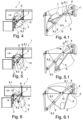
- 1 denotes a corner cupboard 1, the interior 3 of which is accessible via a door 2.
- a fitting 4 is arranged in the interior, which has a shelf 6 and a pivotably mounted guide 5 supporting the shelf.
- the guide 5 is, as can be seen in more detail from the Fig. 1.1 can be seen, is connected to the corner cupboard in an articulated manner on a side wall. The other end of the guide rod 5 pivotally engages the underside of the shelf.
- a self-closing device 7 is also provided on the guide rod 5.
- a driver device is provided in the form of a driver rod 8 with two articulated links 8.1 and 8.2, which are articulated to one another via the swivel joint 9.
- a shaped projection 8.3 is assigned to the guide rod 8.1 in order to further prevent further pivoting in the extended or overextended position of the guide rods 8.1 and 8.2.
- Fig. 2 a state of the parts is shown in which the door 2 has been opened a little manually by an operator. Due to the driver 10 on the lever arm 8.1, which preferably has the shape of a driver pin and which in the closed position (see Fig. 1.1 ) rests on the handlebar 5 of the tray 6, the handlebar 5 has also been pivoted in a forced manner, so that the tray 6 has also moved, as can be seen in more detail from the Fig. 2.1 emerges.
- Fig. 3 and Fig. 3.1 show the further course of the opening movement of the door 2.
- the door 2 has been swung open manually by the operator, whereby the forced movement via the driving pin 10 also causes the Handlebar 5 and thus the shelf 6 have been moved further out of the interior 3 of the corner cupboard 1.
- Fig. 4 and Fig. 4.1 show the state when the door 2 of the corner cabinet 1 is completely open. This position is again brought about by a manual opening movement of the door 3 by an operator.
- the links 8.1 and 8.2 have assumed their extended position or a slightly overextended position, with the molded attachment 8.3 resting on the link 8.2 and thus preventing further movement, since the driver rod 8 is locked in this position of the links 8.1 and 8.2 and thus the door is also locked in this open position.
- the tray 8 can be grasped by the operator and moved further out of the interior 3 of the corner cabinet 1, as is the case with Fig. 5, Fig. 5.1 and Fig. 6 and Fig. 6.1 show.
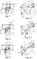
- Fig. 7 now shows the beginning of a retraction process, ie the beginning of a closing movement of the shelf 6 and the door 3.
- the door is still in its locked position with the guides 8.1 and 8.2 in the extended position.
- the tray 6 is manually moved back towards the inside of the cabinet 3 of the cabinet 1 by the operator.
- the guide 5 of the tray 6 moves in the direction of the driving pin 10 of the driving rod 8, with the guides 8.1 and 8.2 still in their extended position ( Fig. 7.1 ).
- the driver rod 8 with the guides 8.1 and 8.2 is still in the extended position, so that the door 2 is still locked.
- the tray 6 is manually moved further towards the inside of the corner cupboard 3 by the operator.
- the guide 5 of the tray 6 moves further towards the driver pin 10 of the driver rod 8, but has not yet reached it.
- Fig. 9 the tray 6 has been manually retracted further by the operator, whereby the guide rod 5 of the tray 6 has now reached the driving pin 10 and can now move the guide rod 8.1. This movement releases the extended position of the driving rod 8 or the guide rods 8.1 and 8.2 and the locking or arresting of the corner cupboard door 2 is also released.
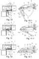
- Fig. 10 10.1 the tray 6 continues to be pushed in manually by the operator. Due to the forced movement coupling between the guide rod 5 of the tray 6 and the drive rod 8 via the drive pin 10, the drive rod 8 folds in further with the guide rods 8.1 and 8.2, whereby the door 3 is automatically taken along.
- Fig. 12 finally shows the final state, in which the closing movement is completed and all parts are back in the closed position.
- the opening and closing movement is therefore extremely simple and convenient to carry out. The necessary construction effort is minimal.
Landscapes
- Hinges (AREA)
- Warehouses Or Storage Devices (AREA)
- Closing And Opening Devices For Wings, And Checks For Wings (AREA)
Description
- Die Erfindung bezieht sich auf einen Eckschrank, insbesondere einen Kücheneckschrank, mit einem über eine Eckschranktür vorderseitig zugänglichen, im Grundriss im Wesentlichen rechteckigen Innenraum mit einem Beschlag, der mit einem im Innenraum des Eckschrankes ortsfest abstützbaren Träger zur Halterung von zumindest einem einteiligen Tablar von halbkreisähnlicher Grundgestalt versehen ist, wobei der Träger zumindest einen das Tablar abstützenden und das Tablar auf einer vorbestimmten Bewegungsbahn aus einer Innenstellung im Innenraum des Eckschrankes in eine im Wesentlichen vor der Türöffnung des Eckschrankes gelegene Außenstellung überführenden Lenker aufweist, der gelenkig an dem Tablar und gelenkig mit einem Eckschrankteil, insbesondere einer Seitenwandung des Eckschrankes, schwenkbeweglich verbunden ist, wobei zwischen der die Türöffnung verschließenden Eckschranktür und dem Tablar eine Mitnehmervorrichtung zur Kopplung der Tür mit dem Tablar während zumindest einem Teil der Öffnungsbewegung und zumindest einem Teil der Schließbewegung der Tür vorgesehen ist gemäß dem Oberbegriff des Patentanspruches 1.
- Aus der
DE 10 2007 009 894 B3 ist ein Eckschrank mit einem Kopplungsmittel mit einem Bolzen und einem Führungsstück als Mitnehmervorrichtung zur Kopplung der Tür vorgesehen. An dem Tablar ist ein Bolzen und ein Führungsstück vorgesehen, wobei der Bolzen bis zu einer Zwischenstellung des Tablars zur Übertragung einer Eckschranktürbewegung auf das Tablar an dem Führungsstück angreift. Hat die Tür eine bestimmte Öffnungsstellung erreicht, kann das Tablar von der Bedienperson aus dem Eckschrank herausgeschwenkt werden. Zum Schließen der Tür ist eine Wiedereinkopplung notwendig, was nicht automatisiert erfolgen kann. Vielmehr muss die Bedienperson diesen Wiedereinkopplungsvorgang durchführen, was in der Praxis aufwendig ist. - Aus der
DE 10 2010 007 287 B4 ist ein Eckschrank der eingangs genannten Art bekannt. An diesem Eckschrank und dem für diesen Eckschrank vorgesehen Beschlag ist die Mitnehmervorrichtung mit einem an der Eckschranktür angebrachten Mitnehmer ausgerüstet, der mit einer schwenkbeweglichen gehaltenen Mitnehmerklinke versehen ist, die von einer Feder belastet ist, wobei die Mitnehmerklinke während einer Öffnungsbewegung der Eckschranktür in einer Kopplungsstellung mit einem Kopplungsglied des Tablars haltbar ist und nach zumindest einer teilweisen Öffnungsstellung der Eckschranktür von dem Kopplungsglied des Tablars im Verlaufe einer weiteren Öffnungsbewegung des Tablars von der Mitnehmerklinke entkoppelbar ist. - Nach Überführung des Tablars in eine Zwischenschwenkstellung oder nach Überführung des Tablars in die Schließstellung ist die Tür wieder mit dem Kopplungsglied zu koppeln. Dieser Kopplungsvorgang gestaltet sich in der Praxis als wenig bedienkomfortabel. Zudem bereitet in der Praxis Schwierigkeiten, dass die Tür in der Türendstellung noch bewegbar ist.
-
TW 201240625 A1 - Es ist Aufgabe der vorliegenden Erfindung, einen Eckschrank der eingangs genannten Art derart weiterzubilden, dass die Tür und das Tablar komfortabel in eine Öffnungs- und in eine Schließstellung zu bringen sind, wobei die Tür und das Tablar durch Bedienung einer Person weniger beschädigt werden können.
- Zur Lösung dieser Aufgabe zeichnet sich der Eckschrank der eingangs genannten Art dadurch aus, dass während der Öffnungsbewegung der Eckschranktür die Lenker des Mitnehmergestänges derart relativ zueinander verschwenkbar sind, dass sie in einer Türöffnungsendstellung in eine Arretierstellung zueinander überführt sind, in der sich das Mitnehmergestänge automatisch derart arretiert, dass die Eckschranktür in dieser Türöffnungsendstellung festgestellt ist, und wobei der Eckschrank so ausgebildet ist, dass das Tablar bei in die Türöffnungsendstellung überführter Eckschranktür und in die Arretierstellung überführtem Mitnehmergestänge von einer Bedienperson greifbar und weiter aus dem Innenraum des Eckschrankes herausbewegbar ist.
- Damit ist ein Eckschrank zur Verfügung gestellt, bei dem über eine Öffnungsbewegung der Tür diese aus der Schließstellung in eine Endöffnungsstellung überführt werden kann, in der sich das Mitnehmergestänge automatisch derart arretiert, dass die Tür in dieser Öffnungsstellung festgestellt werden kann. Dies kann über eine separate Arretiervorrichtung erfolgen, aber auch allein dadurch, dass die zumindest zwei Lenker in eine Strecklage oder leichte Überstrecklage aufgrund der aufgeschwenkten Lenker gebracht werden, so dass die Tür in dieser Öffnungsstellung festgestellt ist. Im Verlaufe der Türbewegung aus der Schließstellung in die Öffnungsstellung wird über den Mitnehmer an dem Mitnehmergestänge selbsttätig das Tablar in eine derartige Öffnungsstellung überführt, so dass es von einer Bedienperson ergriffen und ganz oder teilweise aus dem Schrankinneren in eine Bedienposition zu überführen ist, in der es sich im Wesentlichen vor dem Eckschrank befindet.
- Bei einer nachfolgenden Schließbewegung des Tablars gelangt das Tablar in eine Zwischenschließstellung, in der es wiederum an den Mitnehmer des Mitnehmergestänges zur Anlage kommt und mit einer weiteren Schließbewegung des Tablars das Mitnehmergestänge mit den zumindest zwei Lenkern entriegelt, indem es die Lenker aus ihrer Streck- oder Überstrecklage herausbewegt, so dass die Lenker wieder aufeinander zubewegt werden können. Dabei wird durch die Bewegung des Tablars in die Schließstellung über den Mitnehmer an dem Mitnehmergestänge die Tür von dem Lenker des Tablars mitgenommen.
- Bevorzugterweise ist an dem Lenker des Tablars eine Selbsteinzugsvorrichtung angeordnet, z. B. auf diesem Lenker montiert, so dass bei einer bestimmten Schließstellung die Selbsteinzugsvorrichtung automatisch aktiviert wird und selbsttätig für die weitere Bewegung des Tablars per Selbsteinzug sorgt, wobei automatisch über die Selbsteinzugsvorrichtung über die Lenker des Tablars und über den Mitnehmer und das Mitnehmergestänge die Eckschranktür ebenfalls ohne die Notwendigkeit des Einwirkens der Bedienperson in ihre Schließstellung überführt werden kann. Dies führt insgesamt zu einer außerordentlich komfortablen zu bedienendem Eckschrank mit seinem inneren Beschlag und dem Tablar bzw. den Tablaren, wenn mehrere vorgesehen sind.
- Zur weiteren Erläuterung der Erfindung wird auf weitere Unteransprüche, die nachfolgende Beschreibung und die Zeichnung verwiesen. In der Zeichnung zeigen:
Die Figuren zeigen jeweils in Draufsicht ein Ausführungsbeispiel eines Eckschrankes mit einem inneren Beschlag mit einem Tablar (strichpunktiert dargestellt) und einer Eckschranktür in verschiedenen Öffnungs- und Schließbewegungspositionen der Eckschranktür und des Tablars sowie jeweils zugeordnet zu jeder Figur eine vergrößerte Ausschnittsdarstellung. Im Einzelnen: - Fig. 1:
- Die Darstellung des Eckschrankes in der Schließstellung der Tür und des Tablars;
- Fig. 1.1:
- vergrößert die Einzelheit A nach
Fig. 1 ; - Fig. 2:
- eine zu
Fig. 1 analoge Darstellung bei der die Tür von der Bedienperson per Hand ein wenig geöffnet ist; - Fig. 2.1:
- vergrößert die Einzeldarstellung B nach
Fig. 2 ; - Fig. 3:
- eine analoge Darstellung zu
Fig. 1 bei weiter von der Bedienperson per Hand geöffneter Tür; - Fig. 3.1:
- vergrößert die Einzelheit C nach
Fig. 3 ; - Fig. 4:
- eine zu
Fig. 1 analoge Darstellung in der bis in die Strecklage des Mitnehmergestänges per Hand von der Bedienperson geöffnete Tür (Türfeststellung); - Fig. 4.1:
- eine vergrößerte Darstellung gem. Einzelheit D in
Fig. 4 ; - Fig. 5:
- eine zu der
Fig. 1 analoge Darstellung, bei der sich die Tür in der Türfeststellungsposition befindet und das Tablar weiter per Hand von der Bedienperson ausgefahren wird; - Fig. 5.1:
- vergrößert die Darstellung nach
Fig. 5 ; - Fig. 6:
- eine zu
Fig. 1 analoge Darstellung bei der sich die Tür in der Türfeststellungsposition befindet und das Tablar von der Bedienperson weiter von Hand ausgefahren wird; - Fig. 6.1:
- vergrößert die Einzelheit F in
Fig. 6 ; - Fig. 7:
- eine zu
Fig. 1 analoge Darstellung bei der sich die Tür in der Türfeststellungsposition befindet und das Tablar von der Bedienperson per Hand eingefahren wird; - Fig. 7.1:
- vergrößert die Einzelheit F in
Fig. 7 ; - Fig. 8:
- eine zu
Fig. 1 analoge Darstellung, wo sich in der Türfeststellungsposition befindet und das Tablar von der Bedienperson von Hand weiter eingefahren wird; - Fig. 8.1:
- vergrößert die Einzeldarstellung nach E in
Fig. 8 ; - Fig. 9:
- eine zu
Fig. 1 analoge Darstellung, bei der das Tablar von der Bedienperson per Hand soweit eingeschoben ist, bis der vordere Lenker des Tablars auf den Mitnehmerzapfen des Mitnehmergestänges trifft; - Fig. 9.1:
- vergrößert die Einzeldarstellung D nach
Fig. 9 ; - Fig. 10:
- eine zu
Fig. 1 analoge Darstellung, bei der das Tablar von der Bedienperson per Hand eingeschoben wird und eine Selbsteinzugsvorrichtung am Lenker des Tablars aktiviert wird; - Fig. 10.1:
- die Einzeldarstellung C in
Fig. 10 ; - Fig. 11:
- eine analoge Darstellung zu
Fig. 1 , bei der die Selbsteinzugsvorrichtung den Lenker des Tablars weiter einzieht und über den Mitnehmer des Mitnehmergestänges damit die Tür mitzieht; - Fig. 11.1:
- vergrößert die Einzeldarstellung B in
Fig. 11 ; - Fig. 12:
- eine zu
Fig. 1 analoge Darstellung, bei der der Selbsteinzug das Tablar und die Tür in die Schließstellung gezogen hat und das Mitnehmergestänge eingeklappt ist; - Fig. 12.1:
- vergrößert die Einzeldarstellung A in
Fig. 12 . - In den Figuren der Zeichnung sind grundsätzlich übereinstimmende Teile mit übereinstimmenden Bezugsziffern versehen. Allgemein mit 1 ist ein Eckschrank 1 beziffert, dessen Innenraum 3 über eine Tür 2 zugänglich ist. Im Innenraum ist ein Beschlag 4 angeordnet, der ein Tablar 6 und einen das Tablar abstützenden schwenkbeweglich gehalterten Lenker 5 aufweist. Der Lenker 5 ist, wie näher aus der
Fig. 1.1 ersichtlich ist, an einer Seitenwand gelenkig mit dem Eckschrank verbunden. Das andere Ende des Lenkers 5 greift schwenkbeweglich an der Unterseite des Tablars an. An dem Lenker 5 ist noch eine Selbstzugseinzugsvorrichtung 7 vorgesehen. Des Weiteren ist eine Mitnehmervorrichtung vorgesehen in Gestalt eines Mitnehmergestänges 8 mit zwei gelenkig miteinander verbundenen Lenkern 8.1 und 8.2, die über das Schwenkgelenk 9 gelenkig miteinander verbunden sind. Im Bereich des Schwenkgelenkes 9 ist am Lenker 8.1 ein Formansatz 8.3 zugeordnet, um eine weitere Verschwenkung in der Strecklage oder Überstrecklage der Lenker 8.1 und 8.2 weiter zu verhindern. - In der Darstellung nach
Fig. 1 befinden sich alle Teile in der Schließstellung der Tür 2 und des Tablars 6. - In
Fig. 2 ist ein Zustand der Teile gezeigt, in dem die Tür 2 ein wenig manuell von einer Bedienperson geöffnet worden ist. Aufgrund des Mitnehmers 10 an den Hebelarm 8.1, der bevorzugt die Gestalt eines Mitnehmerzapfens hat und der in der Schließposition (sieheFig. 1.1 ) an dem Lenker 5 des Tablars 6 anliegt, ist der Lenker 5 zwangsgekoppelt ebenfalls verschwenkt worden, so dass das Tablar 6 sich ebenfalls bewegt hat, wie dies auch näher aus derFig. 2.1 hervorgeht. -
Fig. 3 und Fig. 3.1 zeigen den weiteren Verlauf der Öffnungsbewegung der Tür 2. Die Tür 2 ist weiter manuell von der Bedienperson aufgeschwenkt worden, wobei durch die zwangsgekoppelte Bewegung über den Mitnehmerzapfen 10 auch der Lenker 5 und damit das Tablar 6 weiter aus dem Innenraum 3 des Eckschrankes 1 herausbewegt worden sind. -
Fig. 4 und Fig. 4.1 zeigen den Zustand bei vollständig geöffneter Tür 2 des Eckschrankes 1. Diese Position ist wiederum herbeigeführt durch eine manuelle Öffnungsbewegung der Tür 3 durch eine Bedienperson. Wie aber näher aus derFig. 4 und derFig. 4.1 hervorgehen, haben die Lenker 8.1 und 8.2 ihre Strecklage bzw. eine leichte Überstrecklage eingenommen, wobei der Formansatz 8.3 an dem Lenker 8.2 anliegt und so eine weitere Bewegung vermieden wird, da das Mitnehmergestänge 8 in dieser Lage der Lenker 8.1 und 8.2 arretiert ist und damit auch die Tür in dieser Öffnungsstellung festgestellt ist. - In dieser festgestellten Position der Tür und des Mitnehmergestänges 8 kann das Tablar 8 von der Bedienperson ergriffen und weiter aus dem Innenraum 3 des Eckschrankes 1 herausbewegt werden, wie dies die
Fig. 5, Fig. 5.1 und Fig. 6 und Fig. 6.1 zeigen. -
Fig. 7 zeigt nun den Beginn eines Einfahrvorganges, d. h. den Anfang einer Schließbewegung des Tablars 6 und der Tür 3. In derFig. 7 befindet sich die Tür noch in ihrer festgestellten Position bei in Strecklage ausgerichteten Lenkern 8.1 und 8.2. Das Tablar 6 wird manuell von der Bedienperson zurück in Richtung des Schrankinneren 3 des Schrankes 1 bewegt. Der Lenker 5 des Tablars 6 bewegt sich in Richtung des Mitnehmerzapfens 10 des Mitnehmergestänges 8, wobei sich die Lenker 8.1 und 8.2 noch in ihrer Strecklage befinden (Fig. 7.1 ). - In der
Fig. 8 befindet sich das Mitnehmergestänge 8 mit den Lenkern 8.1 und 8.2 immer noch in der Strecklage, so dass die Tür 2 immer noch festgestellt ist. Das Tablar 6 wird manuell von der Bedienperson weiter in Richtung des Schrankinneren 3 des Eckschrankes bewegt. Der Lenker 5 des Tablars 6 bewegt sich weiter in Richtung zum Mitnehmerzapfen 10 des Mitnehmergestänges 8, hat diesen allerdings noch nicht erreicht. - In
Fig. 9 ist das Tablar 6 weiter von der Bedienperson manuell eingefahren worden, wobei jetzt der Lenker 5 des Tablars 6 den Mitnehmerzapfen 10 erreicht hat und jetzt den Lenker 8.1 bewegen kann. Durch diese Bewegung wird die Strecklage des Mitnehmergestänges 8 bzw. der Lenker 8.1 und 8.2 aufgelöst und die Feststellung bzw. Arretierung der Eckschranktür 2 wird ebenfalls aufgelöst. - In
Fig. 10, 10.1 wird das Tablar 6 weiterhin manuell von der Bedienperson eingeschoben. Durch die Bewegungszwangskopplung zwischen dem Lenker 5 des Tablars 6 und des Mitnehmergestänges 8 über den Mitnehmerzapfen 10 klappt das Mitnehmergestänge 8 mit den Lenkern 8.1 und 8.2 weiter ein, wobei die Tür 3 automatisch mitgenommen wird. - In
Fig. 11 hat jetzt der untere Lenker 5 des Tablars 6 die Selbsteinzugsvorrichtung 7 des Lenkers 5 erreicht. Dadurch wird diese automatisch aktiviert und kann aufgrund ihrer inneren Bauteile den weiteren Selbsteinzug des Lenkers 5 des Tablars 8 übernehmen. Durch die Bewegungszwangskopplung zwischen Lenker 5 und des Mitnehmergestänges 8 mit den Lenkern 8.1 und 8.2 werden jetzt selbsttätig das Tablar 6 und die Tür 8 eingezogen. -
Fig. 12 zeigt schließlich den Endzustand, indem die Schließbewegung beendet ist und sich alle Teile wieder in der Schließstellung befinden. Die Öffnungs- und Schließbewegung ist mithin äußerst einfach und komfortabel zu vollziehen. Der notwendige bauliche Aufwand ist gering.
Claims (12)
- Eckschrank (1) mit einem über eine Eckschranktür (2) vorderseitig zugänglichen, im Grundriss im Wesentlichen rechteckigen Innenraum (3) mit einem Beschlag (4), der aus mindestens einem im Innenraum (3) des Eckschrankes (1) ortsfest abstützbaren Träger zur Halterung von zumindest einem einteiligen Tablar (6) von halbkreisähnlicher Grundgestalt besteht, wobei der Träger zumindest einen das Tablar (6) abstützenden und das Tablar (6) auf einer vorbestimmten Bewegungsbahn aus einer Innenstellung im Innenraum (3) des Eckschrankes (1) in eine im Wesentlichen vor der Türöffnung des Eckschrankes (1) gelegene Außenstellung überführenden Lenker (5) aufweist, wobei der Lenker (5) an der Unterseite des Tablars (6) und über einen Trägerbeschlag mit einem Eckschrankteil schwenkbeweglich verbunden ist, wobei zwischen der die Türöffnung verschließenden Eckschranktür (2) und dem Tablar eine Mitnehmervorrichtung zur Kopplung der Eckschranktür (2) mit dem Tablar während zumindest eines Teils der Öffnungsbewegung und während zumindest eines Teils der Schließbewegung der Eckschranktür (2) vorgesehen ist, wobeidie Mitnehmervorrichtung als ein zumindest zwei gelenkig miteinander verbundene Lenker (8.1, 8.2) aufweisendes Mitnehmergestänge (8) ausgebildet ist und zumindest ein Lenker (8.2) des Mitnehmergestänges (8) an der Eckschranktür (2) und ein anderer Lenker (8.1) des Mitnehmergestänges (8) mit einem Eckschrankteil (7) gelenkig verbunden sind, dadurch gekennzeichnet, dass währendder Öffnungsbewegung der Eckschranktür (2) die Lenker (8.1, 8.2) des Mitnehmergestänges (8) derart relativ zueinander verschwenkbar sind, dass sie in einer Türöffnungsendstellung in eine Arretierstellung zueinander überführt sind, in der sich das Mitnehmergestänge (8) automatisch derart arretiert, dass die Eckschranktür (2) in dieser Türöffnungsendstellung festgestellt ist, und wobei der Eckschrank (1) so ausgebildet ist, dass das Tablar (6) bei in die Türöffnungsendstellung überführter Eckschranktür (2) und in die Arretierstellung überführtem Mitnehmergestänge (8) von einer Bedienperson greifbar und weiter aus dem Innenraum (3) des Eckschrankes (1) herausbewegbar ist.
- Eckschrank (1) nach Anspruch 1, dadurch gekennzeichnet, dass an zumindest einem der Lenker (8.1, 8.2) des Mitnehmergestänges (8) einen das Tablar (6) aus der Innenstellung in die Außenstellung überführender Mitnehmer (10) angeordnet ist über den die Tür (2) zumindest über einen Teil ihrer Öffnungsbewegung diese mit der Öffnungsbewegung des Tablars zwangskoppelt ist.
- Eckschranktür (2) nach Anspruch 1 oder 2, dadurch gekennzeichnet, dass über den Mitnehmer die Schließbewegung des Tablars (6) zwangsgekoppelt ist mit der Schließbewegung der Tür (2).
- Eckschrank nach einem der Ansprüche 1 bis 3, dadurch gekennzeichnet, dass der Mitnehmer des Mitnehmergestänges (8) als Mitnehmerzapfen (10) ausgebildet ist.
- Eckschrank nach einem der Ansprüche 1 bis 4, dadurch gekennzeichnet, dass die Lenker (8.1, 8.2) des Mitnehmergestänges (8) im Verlaufe der Türöffnungsbewegung selbsttätig in zumindest eine Strecklage zueinander oder in eine Lage, die ein wenig über die Strecklage der Lenker (8.1, 8.2) des Mitnehmergestänges (8) hinausgeht, überführbar sind und diese Strecklage oder Überstrecklage die Arretierstellung des Mitnehmergestänges (8) bildet.
- Eckschrank nach Anspruch 5, dadurch gekennzeichnet, dass einer der Lenker (8.1, 8.2) des Mitnehmergestänges (8) im Bereich des Schwenklagers (9) der einander zugeordneten Lenker (8.1, 8.2) des Mitnehmergestänges (8) einen Lenkerformansatz (8.3) hat, der sich in der Streck- oder der Überstreckanlage der Lenker (8.1, 8.2) des Mitnehmergestänges (8) an einen Außenbereich des Lenkers (8.2) des Mitnehmergestänges (8) anlegt
- Eckschrank (1) nach einem der Ansprüche 1 bis 6, dadurch gekennzeichnet, dass das Mitnehmergestänge (8) einem im Eckschrank (1) angeordneten vorderen Lenker (5) des Tablars (6) zugeordnet ist.
- Eckschrank nach einem der Ansprüche 1 bis 6, dadurch gekennzeichnet, dass das Mitnehmergestänge (8) einem im Eckschrank (1) angeordneten hinteren Lenker des Tablars (6) zugeordnet ist.
- Eckschrank nach einem der Ansprüche 1 bis 8, dadurch gekennzeichnet, dass einem der Lenker (5) des Tablars (6) eine Selbsteinzugsvorrichtung (7) zugeordnet ist.
- Eckschrank nach Anspruch 9, dadurch gekennzeichnet, dass die Selbsteinzugseinrichtung (7) auf einem der Lenker (5) des Tablars (6) angeordnet ist.
- Eckschrank nach Anspruch 5 und vorzugsweise nach einem der Ansprüche 2 bis 4 oder 6 bis 9, dadurch gekennzeichnet, dass die Tür (3) über eine Schließbewegung des Tablars (6) über den Lenker (5) des Tablars (6), den Mitnehmer (10) und das Mitnehmergestänge (8) zwangsgekoppelt im Schließsinn betätigbar ist unter Auflösung der Arretierung durch Herausbewegen der Lenker (8.1, 8.2) des Mitnehmergestänges (8) aus der Streck- oder Überstrecklage.
- Eckschrank (1) nach Anspruch 9 oder 10 und 11, dadurch gekennzeichnet, dass ab einer bestimmten Schließstellung des Tablars die Selbsteinzugseinrichtung (7) aktiviert wird und die weitere Schließbewegung der Tür (3) und des Tablars (6) über die Selbsteinzugsvorrichtung (7) erfolgt durch Kopplung des Lenkers (5) des Tablars (6) mit dem Mitnehmergestänge (8) über den Mitnehmer (10).
Applications Claiming Priority (1)
| Application Number | Priority Date | Filing Date | Title |
|---|---|---|---|
| DE202019102333.3U DE202019102333U1 (de) | 2019-04-25 | 2019-04-25 | Eckschrank mit einem inneren Tablar und einer Mitnehmervorrichtung für die Tür |
Publications (2)
| Publication Number | Publication Date |
|---|---|
| EP3729999A1 EP3729999A1 (de) | 2020-10-28 |
| EP3729999B1 true EP3729999B1 (de) | 2024-11-06 |
Family
ID=66816868
Family Applications (1)
| Application Number | Title | Priority Date | Filing Date |
|---|---|---|---|
| EP20159865.3A Active EP3729999B1 (de) | 2019-04-25 | 2020-02-27 | Eckschrank mit einem inneren tablar und einer mitnehmervorrichtung für die tür |
Country Status (4)
| Country | Link |
|---|---|
| EP (1) | EP3729999B1 (de) |
| DE (1) | DE202019102333U1 (de) |
| ES (1) | ES3007817T3 (de) |
| PL (1) | PL3729999T3 (de) |
Family Cites Families (4)
| Publication number | Priority date | Publication date | Assignee | Title |
|---|---|---|---|---|
| EP1427309A1 (de) * | 2001-09-12 | 2004-06-16 | VIBO S.p.A. | Gerät zum bewegen von möbelstücken |
| DE102007009894C5 (de) | 2007-03-01 | 2010-05-12 | Hetal-Werke Franz Hettich Gmbh & Co. Kg | Eckschrank, insbesondere Kücheneckschrank |
| DE102010007287B4 (de) | 2010-02-08 | 2015-04-16 | Kesseböhmer Holding e.K. | Beschlag für Eckschränke mit einem Mitnehmer für die Schranktür |
| TW201240625A (en) * | 2012-05-28 | 2012-10-16 | A & D Jasmine Internat Co Ltd | Corner cabinets stretching device |
-
2019
- 2019-04-25 DE DE202019102333.3U patent/DE202019102333U1/de active Active
-
2020
- 2020-02-27 ES ES20159865T patent/ES3007817T3/es active Active
- 2020-02-27 EP EP20159865.3A patent/EP3729999B1/de active Active
- 2020-02-27 PL PL20159865.3T patent/PL3729999T3/pl unknown
Also Published As
| Publication number | Publication date |
|---|---|
| ES3007817T3 (en) | 2025-03-20 |
| DE202019102333U1 (de) | 2019-05-27 |
| EP3729999A1 (de) | 2020-10-28 |
| PL3729999T3 (pl) | 2025-03-10 |
Similar Documents
| Publication | Publication Date | Title |
|---|---|---|
| EP2713816B1 (de) | Beschlag für eckschränke | |
| DE102016013077B4 (de) | Möbel mit einem motorischen Antrieb für ein Möbelteil | |
| EP3151718B1 (de) | Geschirrspülmaschine, insbesondere haushaltsgeschirrspülmaschine | |
| EP3315047B1 (de) | Steuervorrichtung zur bewegungssteuerung einer eckschranktür eines eckschranks | |
| EP2793655B1 (de) | Anordnung zum bewegen eines bewegbaren möbelteils | |
| DE102010007287B4 (de) | Beschlag für Eckschränke mit einem Mitnehmer für die Schranktür | |
| DE19906395A1 (de) | Theke zum Darbieten und/oder Verkaufen von Waren | |
| DE102014213986A1 (de) | Haushaltsgeschirrspülmaschine | |
| DE1529652C2 (de) | Faltbare Schranktür | |
| DE212018000218U1 (de) | Möbelbeschlag zum Bewegen eines Möbelteiles | |
| EP3729999A1 (de) | Eckschrank mit einem inneren tablar und einer mitnehmervorrichtung für die tür | |
| DE937457C (de) | Einrichtung zum OEffnen und Schliessen, vornehmlich des rueckwaertigen Planteiles anLastkraftwagen, zum Zwecke des Be- und Entladens | |
| DE19522573A1 (de) | Sicherheitsschrank | |
| DE4304034C2 (de) | Vorrichtung an Verwandlungsbeschlägen für Polstermöbel | |
| DE2317553C2 (de) | Vorrichtung zum Öffnen des Deckels beim Entleeren von Behältern, beispielsweise Müllgefässen | |
| DE2156572B2 (de) | Vorrichtung zur Verriegelung eines Wechselbehälters mit einer Müllpresse | |
| AT224494B (de) | Betätigungseinrichtung für Dreh-Kipp-Fenster, -Türen od. ähnl. Öffnungsverschlüsse | |
| DE10018732A1 (de) | Auswerfervorrichtung für eine Klappenanordnung, insbesondere eine Kraftfahrzeug-Heckklappenanordnung | |
| DE2018211C3 (de) | Haltevorrichtung für Abfalltüten | |
| DE7811011U1 (de) | Klappenbeschlag | |
| DE2357738C2 (de) | Nachttisch mit seitlich einschwenkbarer und ausfahrbarer Tischplatte | |
| DE2944940C2 (de) | Vorrichtung zur seitlichen Abtrennung von benachbarten Viehständen | |
| DE854665C (de) | Druckmittelantrieb fuer Schwenk-Schiebetueren, insbesondere fuer Fahrzeugtueren | |
| DE10114658B4 (de) | Vorrichtung zum Begrenzen einer Öffnungsbewegung einer Schranktür, insbesondere einer Klapptür | |
| DE204156C (de) |
Legal Events
| Date | Code | Title | Description |
|---|---|---|---|
| PUAI | Public reference made under article 153(3) epc to a published international application that has entered the european phase |
Free format text: ORIGINAL CODE: 0009012 |
|
| STAA | Information on the status of an ep patent application or granted ep patent |
Free format text: STATUS: THE APPLICATION HAS BEEN PUBLISHED |
|
| AK | Designated contracting states |
Kind code of ref document: A1 Designated state(s): AL AT BE BG CH CY CZ DE DK EE ES FI FR GB GR HR HU IE IS IT LI LT LU LV MC MK MT NL NO PL PT RO RS SE SI SK SM TR |
|
| AX | Request for extension of the european patent |
Extension state: BA ME |
|
| STAA | Information on the status of an ep patent application or granted ep patent |
Free format text: STATUS: REQUEST FOR EXAMINATION WAS MADE |
|
| 17P | Request for examination filed |
Effective date: 20201216 |
|
| RBV | Designated contracting states (corrected) |
Designated state(s): AL AT BE BG CH CY CZ DE DK EE ES FI FR GB GR HR HU IE IS IT LI LT LU LV MC MK MT NL NO PL PT RO RS SE SI SK SM TR |
|
| STAA | Information on the status of an ep patent application or granted ep patent |
Free format text: STATUS: EXAMINATION IS IN PROGRESS |
|
| 17Q | First examination report despatched |
Effective date: 20230317 |
|
| GRAP | Despatch of communication of intention to grant a patent |
Free format text: ORIGINAL CODE: EPIDOSNIGR1 |
|
| STAA | Information on the status of an ep patent application or granted ep patent |
Free format text: STATUS: GRANT OF PATENT IS INTENDED |
|
| INTG | Intention to grant announced |
Effective date: 20240423 |
|
| GRAJ | Information related to disapproval of communication of intention to grant by the applicant or resumption of examination proceedings by the epo deleted |
Free format text: ORIGINAL CODE: EPIDOSDIGR1 |
|
| STAA | Information on the status of an ep patent application or granted ep patent |
Free format text: STATUS: EXAMINATION IS IN PROGRESS |
|
| GRAP | Despatch of communication of intention to grant a patent |
Free format text: ORIGINAL CODE: EPIDOSNIGR1 |
|
| STAA | Information on the status of an ep patent application or granted ep patent |
Free format text: STATUS: GRANT OF PATENT IS INTENDED |
|
| INTC | Intention to grant announced (deleted) | ||
| GRAS | Grant fee paid |
Free format text: ORIGINAL CODE: EPIDOSNIGR3 |
|
| INTG | Intention to grant announced |
Effective date: 20240709 |
|
| P01 | Opt-out of the competence of the unified patent court (upc) registered |
Free format text: CASE NUMBER: APP_47571/2024 Effective date: 20240819 |
|
| GRAA | (expected) grant |
Free format text: ORIGINAL CODE: 0009210 |
|
| STAA | Information on the status of an ep patent application or granted ep patent |
Free format text: STATUS: THE PATENT HAS BEEN GRANTED |
|
| AK | Designated contracting states |
Kind code of ref document: B1 Designated state(s): AL AT BE BG CH CY CZ DE DK EE ES FI FR GB GR HR HU IE IS IT LI LT LU LV MC MK MT NL NO PL PT RO RS SE SI SK SM TR |
|
| REG | Reference to a national code |
Ref country code: GB Ref legal event code: FG4D Free format text: NOT ENGLISH |
|
| REG | Reference to a national code |
Ref country code: CH Ref legal event code: EP |
|
| REG | Reference to a national code |
Ref country code: DE Ref legal event code: R096 Ref document number: 502020009661 Country of ref document: DE |
|
| REG | Reference to a national code |
Ref country code: IE Ref legal event code: FG4D Free format text: LANGUAGE OF EP DOCUMENT: GERMAN |
|
| REG | Reference to a national code |
Ref country code: LT Ref legal event code: MG9D |
|
| REG | Reference to a national code |
Ref country code: NL Ref legal event code: MP Effective date: 20241106 |
|
| REG | Reference to a national code |
Ref country code: ES Ref legal event code: FG2A Ref document number: 3007817 Country of ref document: ES Kind code of ref document: T3 Effective date: 20250320 |
|
| PG25 | Lapsed in a contracting state [announced via postgrant information from national office to epo] |
Ref country code: HR Free format text: LAPSE BECAUSE OF FAILURE TO SUBMIT A TRANSLATION OF THE DESCRIPTION OR TO PAY THE FEE WITHIN THE PRESCRIBED TIME-LIMIT Effective date: 20241106 Ref country code: PT Free format text: LAPSE BECAUSE OF FAILURE TO SUBMIT A TRANSLATION OF THE DESCRIPTION OR TO PAY THE FEE WITHIN THE PRESCRIBED TIME-LIMIT Effective date: 20250306 Ref country code: IS Free format text: LAPSE BECAUSE OF FAILURE TO SUBMIT A TRANSLATION OF THE DESCRIPTION OR TO PAY THE FEE WITHIN THE PRESCRIBED TIME-LIMIT Effective date: 20250306 |
|
| PG25 | Lapsed in a contracting state [announced via postgrant information from national office to epo] |
Ref country code: FI Free format text: LAPSE BECAUSE OF FAILURE TO SUBMIT A TRANSLATION OF THE DESCRIPTION OR TO PAY THE FEE WITHIN THE PRESCRIBED TIME-LIMIT Effective date: 20241106 Ref country code: NL Free format text: LAPSE BECAUSE OF FAILURE TO SUBMIT A TRANSLATION OF THE DESCRIPTION OR TO PAY THE FEE WITHIN THE PRESCRIBED TIME-LIMIT Effective date: 20241106 |
|
| PG25 | Lapsed in a contracting state [announced via postgrant information from national office to epo] |
Ref country code: BG Free format text: LAPSE BECAUSE OF FAILURE TO SUBMIT A TRANSLATION OF THE DESCRIPTION OR TO PAY THE FEE WITHIN THE PRESCRIBED TIME-LIMIT Effective date: 20241106 |
|
| PG25 | Lapsed in a contracting state [announced via postgrant information from national office to epo] |
Ref country code: NO Free format text: LAPSE BECAUSE OF FAILURE TO SUBMIT A TRANSLATION OF THE DESCRIPTION OR TO PAY THE FEE WITHIN THE PRESCRIBED TIME-LIMIT Effective date: 20250206 |
|
| PG25 | Lapsed in a contracting state [announced via postgrant information from national office to epo] |
Ref country code: LV Free format text: LAPSE BECAUSE OF FAILURE TO SUBMIT A TRANSLATION OF THE DESCRIPTION OR TO PAY THE FEE WITHIN THE PRESCRIBED TIME-LIMIT Effective date: 20241106 Ref country code: GR Free format text: LAPSE BECAUSE OF FAILURE TO SUBMIT A TRANSLATION OF THE DESCRIPTION OR TO PAY THE FEE WITHIN THE PRESCRIBED TIME-LIMIT Effective date: 20250207 |
|
| PG25 | Lapsed in a contracting state [announced via postgrant information from national office to epo] |
Ref country code: RS Free format text: LAPSE BECAUSE OF FAILURE TO SUBMIT A TRANSLATION OF THE DESCRIPTION OR TO PAY THE FEE WITHIN THE PRESCRIBED TIME-LIMIT Effective date: 20250206 |
|
| PG25 | Lapsed in a contracting state [announced via postgrant information from national office to epo] |
Ref country code: SM Free format text: LAPSE BECAUSE OF FAILURE TO SUBMIT A TRANSLATION OF THE DESCRIPTION OR TO PAY THE FEE WITHIN THE PRESCRIBED TIME-LIMIT Effective date: 20241106 |
|
| PG25 | Lapsed in a contracting state [announced via postgrant information from national office to epo] |
Ref country code: DK Free format text: LAPSE BECAUSE OF FAILURE TO SUBMIT A TRANSLATION OF THE DESCRIPTION OR TO PAY THE FEE WITHIN THE PRESCRIBED TIME-LIMIT Effective date: 20241106 |
|
| PG25 | Lapsed in a contracting state [announced via postgrant information from national office to epo] |
Ref country code: EE Free format text: LAPSE BECAUSE OF FAILURE TO SUBMIT A TRANSLATION OF THE DESCRIPTION OR TO PAY THE FEE WITHIN THE PRESCRIBED TIME-LIMIT Effective date: 20241106 |
|
| PG25 | Lapsed in a contracting state [announced via postgrant information from national office to epo] |
Ref country code: RO Free format text: LAPSE BECAUSE OF FAILURE TO SUBMIT A TRANSLATION OF THE DESCRIPTION OR TO PAY THE FEE WITHIN THE PRESCRIBED TIME-LIMIT Effective date: 20241106 |
|
| PG25 | Lapsed in a contracting state [announced via postgrant information from national office to epo] |
Ref country code: SK Free format text: LAPSE BECAUSE OF FAILURE TO SUBMIT A TRANSLATION OF THE DESCRIPTION OR TO PAY THE FEE WITHIN THE PRESCRIBED TIME-LIMIT Effective date: 20241106 |
|
| PG25 | Lapsed in a contracting state [announced via postgrant information from national office to epo] |
Ref country code: CZ Free format text: LAPSE BECAUSE OF FAILURE TO SUBMIT A TRANSLATION OF THE DESCRIPTION OR TO PAY THE FEE WITHIN THE PRESCRIBED TIME-LIMIT Effective date: 20241106 |
|
| REG | Reference to a national code |
Ref country code: DE Ref legal event code: R097 Ref document number: 502020009661 Country of ref document: DE |
|
| PG25 | Lapsed in a contracting state [announced via postgrant information from national office to epo] |
Ref country code: SE Free format text: LAPSE BECAUSE OF FAILURE TO SUBMIT A TRANSLATION OF THE DESCRIPTION OR TO PAY THE FEE WITHIN THE PRESCRIBED TIME-LIMIT Effective date: 20241106 |
|
| PLBE | No opposition filed within time limit |
Free format text: ORIGINAL CODE: 0009261 |
|
| STAA | Information on the status of an ep patent application or granted ep patent |
Free format text: STATUS: NO OPPOSITION FILED WITHIN TIME LIMIT |
|
| PG25 | Lapsed in a contracting state [announced via postgrant information from national office to epo] |
Ref country code: MC Free format text: LAPSE BECAUSE OF FAILURE TO SUBMIT A TRANSLATION OF THE DESCRIPTION OR TO PAY THE FEE WITHIN THE PRESCRIBED TIME-LIMIT Effective date: 20241106 |
|
| REG | Reference to a national code |
Ref country code: CH Ref legal event code: PL |
|
| 26N | No opposition filed |
Effective date: 20250807 |
|
| PG25 | Lapsed in a contracting state [announced via postgrant information from national office to epo] |
Ref country code: LU Free format text: LAPSE BECAUSE OF NON-PAYMENT OF DUE FEES Effective date: 20250227 |
|
| PG25 | Lapsed in a contracting state [announced via postgrant information from national office to epo] |
Ref country code: CH Free format text: LAPSE BECAUSE OF NON-PAYMENT OF DUE FEES Effective date: 20250228 |
|
| REG | Reference to a national code |
Ref country code: BE Ref legal event code: MM Effective date: 20250228 |
|
| PG25 | Lapsed in a contracting state [announced via postgrant information from national office to epo] |
Ref country code: BE Free format text: LAPSE BECAUSE OF NON-PAYMENT OF DUE FEES Effective date: 20250228 |
|
| PG25 | Lapsed in a contracting state [announced via postgrant information from national office to epo] |
Ref country code: IE Free format text: LAPSE BECAUSE OF NON-PAYMENT OF DUE FEES Effective date: 20250227 |
|
| PGFP | Annual fee paid to national office [announced via postgrant information from national office to epo] |
Ref country code: GB Payment date: 20260219 Year of fee payment: 7 |
|
| PGFP | Annual fee paid to national office [announced via postgrant information from national office to epo] |
Ref country code: ES Payment date: 20260319 Year of fee payment: 7 |
|
| PGFP | Annual fee paid to national office [announced via postgrant information from national office to epo] |
Ref country code: DE Payment date: 20260217 Year of fee payment: 7 |
|
| PG25 | Lapsed in a contracting state [announced via postgrant information from national office to epo] |
Ref country code: AT Free format text: LAPSE BECAUSE OF NON-PAYMENT OF DUE FEES Effective date: 20250227 |
|
| PGFP | Annual fee paid to national office [announced via postgrant information from national office to epo] |
Ref country code: IT Payment date: 20260227 Year of fee payment: 7 |
|
| REG | Reference to a national code |
Ref country code: AT Ref legal event code: MM01 Ref document number: 1738383 Country of ref document: AT Kind code of ref document: T Effective date: 20250227 |
|
| PGFP | Annual fee paid to national office [announced via postgrant information from national office to epo] |
Ref country code: FR Payment date: 20260223 Year of fee payment: 7 |
|
| PGFP | Annual fee paid to national office [announced via postgrant information from national office to epo] |
Ref country code: TR Payment date: 20260220 Year of fee payment: 7 |
|
| PGFP | Annual fee paid to national office [announced via postgrant information from national office to epo] |
Ref country code: PL Payment date: 20260218 Year of fee payment: 7 |
|
| PG25 | Lapsed in a contracting state [announced via postgrant information from national office to epo] |
Ref country code: CY Free format text: LAPSE BECAUSE OF FAILURE TO SUBMIT A TRANSLATION OF THE DESCRIPTION OR TO PAY THE FEE WITHIN THE PRESCRIBED TIME-LIMIT Effective date: 20241106 |
|
| PG25 | Lapsed in a contracting state [announced via postgrant information from national office to epo] |
Ref country code: LT Free format text: LAPSE BECAUSE OF FAILURE TO SUBMIT A TRANSLATION OF THE DESCRIPTION OR TO PAY THE FEE WITHIN THE PRESCRIBED TIME-LIMIT Effective date: 20241106 |